corrigendum 1 dated march 12, 2021 to tender specification
TRANSCRIPT
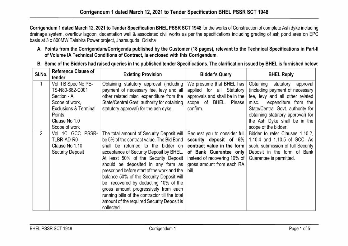
Corrigendum 1 dated March 12, 2021 to Tender Specification BHEL PSSR SCT 1948
BHEL PSSR SCT 1948 Corrigendum 1 Page 1 of 5
Corrigendum 1 dated March 12, 2021 to Tender Specification BHEL PSSR SCT 1948 for the works of Construction of complete Ash dyke including drainage system, overflow lagoon, decantation well & associated civil works as per the specifications including grading of ash pond area on EPC basis at 3 x 800MW Talabira Power project, Jharsuguda, Odisha
A. Points from the Corrigendum/Corrigenda published by the Customer (18 pages), relevant to the Technical Specifications in Part-II of Volume IA Technical Conditions of Contract, is enclosed with this Corrigendum.
B. Some of the Bidders had raised queries in the published tender Specifications. The clarification issued by BHEL is furnished below:
Sl.No. Reference Clause of tender Existing Provision Bidder's Query BHEL Reply
1 Vol II B Spec No PE-TS-N80-682-C001 Section - A Scope of work, Exclusions & Terminal Points Clause No 1.0 Scope of work
Obtaining statutory approval (including payment of necessary fee, levy and all other related misc. expenditure from the State/Central Govt. authority for obtaining statutory approval) for the ash dyke.
We presume that BHEL has applied for all Statutory approvals and shall be in the scope of BHEL. Please confirm.
Obtaining statutory approval (including payment of necessary fee, levy and all other related misc. expenditure from the State/Central Govt. authority for obtaining statutory approval) for the Ash Dyke shall be in the scope of the bidder.
2 Vol 1C GCC PSSR-TLBR-AD-R0 Clause No 1.10 Security Deposit
The total amount of Security Deposit will be 5% of the contract value. The Bid Bond shall be returned to the bidder on acceptance of Security Deposit by BHEL. At least 50% of the Security Deposit should be deposited in any form as prescribed before start of the work and the balance 50% of the Security Deposit will be recovered by deducting 10% of the gross amount progressively from each running bills of the contractor till the total amount of the required Security Deposit is collected.
Request you to consider full security deposit of 5% contract value in the form of Bank Guarantee only instead of recovering 10% of gross amount from each RA bill
Bidder to refer Clauses 1.10.2, 1.10.4 and 1.10.5 of GCC. As such, submission of full Security Deposit in the form of Bank Guarantee is permitted.

Corrigendum 1 dated March 12, 2021 to Tender Specification BHEL PSSR SCT 1948
BHEL PSSR SCT 1948 Corrigendum 1 Page 2 of 5
Sl.No. Reference Clause of tender Existing Provision Bidder's Query BHEL Reply
3 Vol 1B SCC Clause No 10.3 & 10.4
Release of payment in each running bill including PVC Bills where ever applicable will be restricted to 95% of the value of work admitted as per stages of progressive pro rata payments. The 5% thus remaining shall be treated as ‘Retention Amount’ and shall be released as per terms specified in the General Conditions of Contract.
Kindly mention the total amount of Retention money for overall contract value.Request you to consider retention amount in the form of Bank Guarantee instead of deducting from each RA bill
Bidder to refer Cl. No. 1.7.4.2 & 1.7.4.3 of TCC. Retention amount in the form of Bank Guarantee is not acceptable.
4 Vol 1C GCC PSSR-TLBR-AD-R0 Clause No 2.7.9 Liquidated damages /Price Reduction
½ % of the Contract Price (including Price variation, if any) per week of delay or part thereof subject to a maximum of 5 % of the Total Contract Price(including Price variation, if any), by way of reduction in price for delay and not as penalty.
Request you to Limit LD of 0.2% per week of delay with max of 5% of contract value.
Tender condition prevails.
5 Vol 1A Part -I Terms of Payment Technical conditons of contract Clause No 1.7.3 Advance for Mobilization
Interest bearing advance for Mobilization, limited to 5% of the contract value will be paid against submission of bank guarantee of at least 110% of the advance valid for the contract period, which will be recovered from the first running bill onwardsThe advance for mobilization shall be paid as under2% of contract value after receipt of initial Security Deposit and additional security deposit as applicable if any1.5% of contract value on completion of site Mobilization of Machinery & T&P1.5% of contract value
Please provide Interest free advance of 5% of Contract Value in 2 equal installments
Tender condition prevails.

Corrigendum 1 dated March 12, 2021 to Tender Specification BHEL PSSR SCT 1948
BHEL PSSR SCT 1948 Corrigendum 1 Page 3 of 5
Sl.No. Reference Clause of tender Existing Provision Bidder's Query BHEL Reply
on completion of site Mobilization of Machinery & T&P
6 Vol II B Spec No PE-TS-N80-682-C001 Section - 1 Page No 68 of 118 Special Technical Requirements Bund protection for Nallah near Ash Dyke
Bund protection for Nallah near Ash Dyke is under the scope of Bidder. RCC/Stone masonry retaining wall from 1m below bottom of bund upto a height 1M above MFL of Bhedan River/nallah. Bidder shall make arrangements to get the MFL of the nallah/River obtained from Odisha state govt authorities. Bidder shall inspect the site before quoting the rates.
Please provide Drainage study report of Bhedan river for construction of Bund. Request ot provide MFL of the Bhedan River
Area Drainage Study for NLC Talabira Thermal Power Project, Stage I (3x800 MW) is attached. (54 pages)
7 Vol II GI/Section-1, 4.23.10 Ash Dyke
Ash dyke shall be constructed by optimized cutting/filling required to build up storage capacity as indicated in Mechanical Volume. With top of the bund shall not exceed 204.0m including free board of 1.5 m and bottom level shall be kept above the ground water table.
As per BH-27 water table indicated at 197.7m level, Hence if we provide bottom RL i.e +198.00 above water table maximum height will be 6m(i.e 204-198=6m) only, please confirm?
Relevant pages from NLCIL's Corrigendum-8 is attached. (18 pages) Bidder to refer Sl. No. 3 of the same for height of embankment and ground water table.
8 Vol II GI/Section-1, 4.23.10 Ash Dyke
Top width of embankment shall be minimum 6 m having a 150mm consolidated thick WBM road (75mm consolidated thick in two layers)of 4.00 m wide over 230mm mm stone boulder sub base. Higher top width as per approved drawings shall be provided if pipelines are to be run over the dyke top.
Top width embankment shall be 6m with 4m WBM road.Please provide protection works/finishing for either side 1m shoulders at top of dyke.
No protection is required at the top of embankment.

Corrigendum 1 dated March 12, 2021 to Tender Specification BHEL PSSR SCT 1948
BHEL PSSR SCT 1948 Corrigendum 1 Page 4 of 5
Sl.No. Reference Clause of tender Existing Provision Bidder's Query BHEL Reply
9 Vol II GI/Section-1, 4.23.10 Ash Dyke
Ash Dyke Slope Protection Works: …. Minimum 30 cm thick stone pitching with Riprap arrangement hand placed as per IS:8237…
As per IS:8237 hand placed riprap shall be 300mm thick laid over filter material of 300thk with 2 layers of each 150mm thick, please confirm.
Bidder to follow the specification.
10 Vol II B Spec No PE-TS-N80-682-C001 Section - A Scope of work, Exclusions & Terminal Points Clause No 1.0 Scope of work
Ash dyke (starter dyke) There is no clarity on Volume of Ash Pond, Please provide the same
The capacity of ash dyke shall be approx. 62,00,000 m3.
11 Vol II B Spec No PE-TS-N80-682-C001 Section - A Scope of work, Exclusions & Terminal Points Clause No 1.0 Scope of work point b.
Peripheral road and drain around the toe of embankment including connection of peripheral drain with nearest natural drain or nallah.
Please provide Type of road and width for peripheral road.
4.0m wide BT inspection road shall be provided along the outer periphery of dyke.
12 Drawing No. 18A03-DWG-C-0008
GA of Ash Dyke Please provide side slopes for ash pond (outside the Bund).
Side slopes shall be minimum 2.5 Horizontal to 1 Vertical. 3m wide berms shall be provided for all slopes at about 6 m height intervals. Berm is not envisaged in the first 8 m lift.
13 Vol 1A Part -I Chapter-II-Scope of Works-Clause 1.2.2.
Decantation well Please provide Decantation well details and also clarify it is through pumping or gravity
No decantation arrangement is needed.
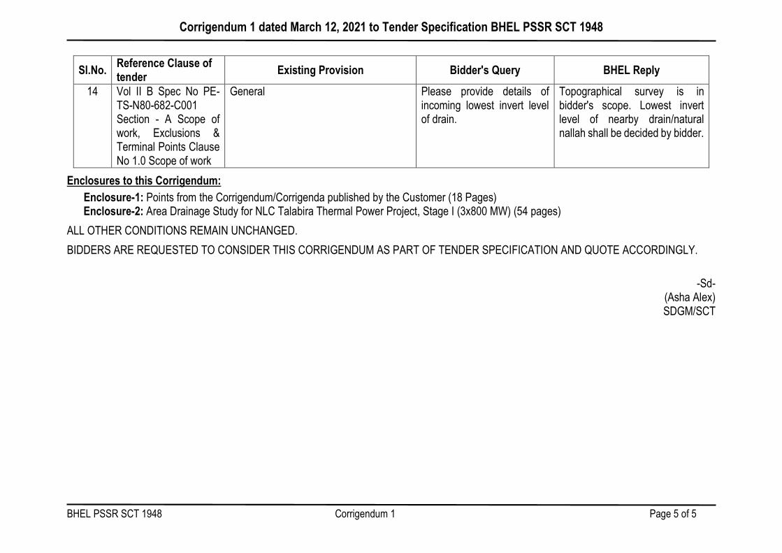
Corrigendum 1 dated March 12, 2021 to Tender Specification BHEL PSSR SCT 1948
BHEL PSSR SCT 1948 Corrigendum 1 Page 5 of 5
Sl.No. Reference Clause of tender Existing Provision Bidder's Query BHEL Reply
14 Vol II B Spec No PE-TS-N80-682-C001 Section - A Scope of work, Exclusions & Terminal Points Clause No 1.0 Scope of work
General Please provide details of incoming lowest invert level of drain.
Topographical survey is in bidder's scope. Lowest invert level of nearby drain/natural nallah shall be decided by bidder.
Enclosures to this Corrigendum: Enclosure-1: Points from the Corrigendum/Corrigenda published by the Customer (18 Pages) Enclosure-2: Area Drainage Study for NLC Talabira Thermal Power Project, Stage I (3x800 MW) (54 pages)
ALL OTHER CONDITIONS REMAIN UNCHANGED. BIDDERS ARE REQUESTED TO CONSIDER THIS CORRIGENDUM AS PART OF TENDER SPECIFICATION AND QUOTE ACCORDINGLY.
-Sd-
(Asha Alex) SDGM/SCT

BHEL PSSR SCT 1948 Corrigendum 1
Enclosure 1 to Corrigendum 1 dated March 12, 2021
to Tender Specification BHEL PSSR SCT 1948
POINTS FROM THE CORRIGENDUM/CORRIGENDA
PUBLISHED BY THE CUSTOMER (18 Pages)

BHED
AN R
IVER
BHED
AN R
IVER
BHED
AN
RIVER
BH
EDA
N R
IVER
N
EW
S
GATE #2 WITHSECURITY OFFICE
GATE #3 WITHSECURITY OFFICE
GATE #4 CHECKPOST
CHECKPOST
GATE#1MAIN GATE
COMPLEX WITHSECURITY AND
TIME OFFICE
RL. VARIES
CHECKPOSTCHECKPOST
CHECKPOST
01/01/2021 S:\Design_Comments\ODISHA TPP\CTO WORKS IN EPC SCOPE\(B) THERMAL POWER PLANT AREA\B1 - Site Grading Layout R2 (With Latest Layout).dwg
ESAKKIMUTHU.S.S
A0
ADGM/D
DGM/D
SCALE: DRG No:
EE/D
SIGNATURE DATE
DGM/C
DRN BY
REV. AMENDMENTSDATE CM/DEE/D DGM/D DGM/C
DCE/D OFFICE OF THE CHIEF GENERAL MANAGER / CIVIL / CTO
NLC India Limited(formerly Neyveli Lignite Corporation Limited)
('Navratna' - A Government of India Enterprise)
NEYVELI- 607 801,TAMIL NADU
DCE/D
CREATING WEALTHFOR WELL BEING
Page 7 of 294
Sl. No.
Sl. No as in
pre bid query
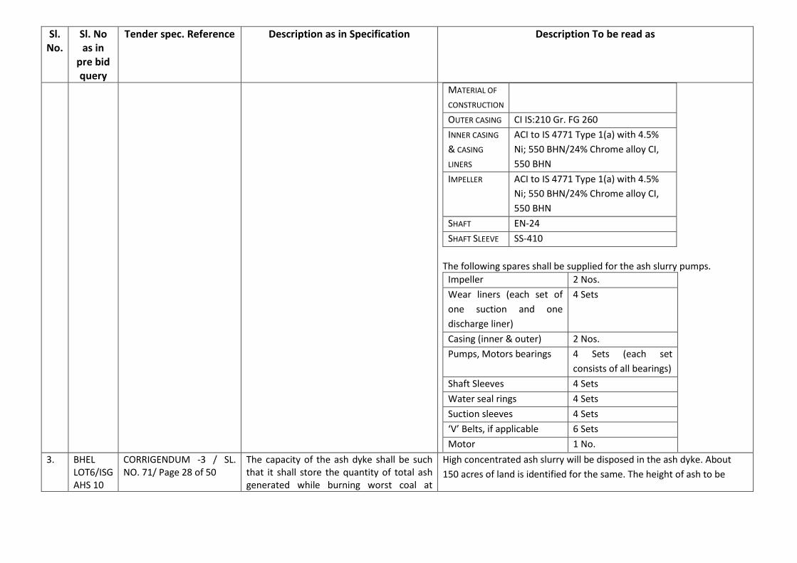
Tender spec. Reference Description as in Specification Description To be read as
MATERIAL OF
CONSTRUCTION
OUTER CASING CI IS:210 Gr. FG 260
INNER CASING
& CASING
LINERS
ACI to IS 4771 Type 1(a) with 4.5%
Ni; 550 BHN/24% Chrome alloy CI,
550 BHN
IMPELLER ACI to IS 4771 Type 1(a) with 4.5%
Ni; 550 BHN/24% Chrome alloy CI,
550 BHN
SHAFT EN-24
SHAFT SLEEVE SS-410
The following spares shall be supplied for the ash slurry pumps.
Impeller 2 Nos.
Wear liners (each set of
one suction and one
discharge liner)
4 Sets
Casing (inner & outer) 2 Nos.
Pumps, Motors bearings 4 Sets (each set
consists of all bearings)
Shaft Sleeves 4 Sets
Water seal rings 4 Sets
Suction sleeves 4 Sets
‘V’ Belts, if applicable 6 Sets
Motor 1 No.
3. BHEL LOT6/ISG AHS 10
CORRIGENDUM -3 / SL. NO. 71/ Page 28 of 50
The capacity of the ash dyke shall be such that it shall store the quantity of total ash generated while burning worst coal at
High concentrated ash slurry will be disposed in the ash dyke. About
150 acres of land is identified for the same. The height of ash to be
Page 177 of 294

Sl. No.
Sl. No as in
pre bid query
Tender spec. Reference Description as in Specification Description To be read as
& PEM, Sl.No.3 to 6 & 1764 of L&T Lot-4
SECTION-B, Vol-II H1/ Clause no. 3.03.06 & Vol. II-H1 AHS/Section B/ Page 8 of 90/ 3.03.04
100% TMCR from all the three units for two years and will be constructed on the existing ground along the periphery of the HCSD area. The bulk density to be considered for the calculation of ash dyke capacity shall be 1.4t/m3.
dumped in the ash dyke shall be about 8.5m with bottom level of ash
dyke as 194M and will be constructed on the area shown in the Plot
Plan.
The capacity of the ash dyke shall be arrived considering ash generated
while burning worst coal at 100% TMCR from all the three units at 85%
PLF and will be constructed on the existing ground along the periphery
of the HCSD area. The bulk density to be considered for the calculation
of ash dyke capacity shall be 1.4t/m3.
The static lift and pumping distance to be considered for HCSD pumping
design are 40 meters and 7000 meters excluding garlanding.
Each discharge line from the pump house to mines & ash dyke shall be
7000m and 4000m respectively excluding valves & fittings.
In addition, 20000m pipe shall be considered for garlanding both mines
void and ash dyke excluding valves & fittings and including raiser branch
pipes for discharge of ash in ash dyke. Garlanding scheme shall be as
per the indicative scheme (Appendix-E) provided in the Corrigendum-5.
The top surface level of the mine void area shall be considered as 211M
for HCSD pump head calculation.
4. BHEL/ISG
Lot-4,
Sl.No.20
Corrigendum_5_Pre_bid_
08.01.2021_841_1336/
Sl no. 7/page 372 of 496
ASH HANDLING SYSTEM
Bidder / Sub-Contractor should have executed at least one number ash handling plant/system involving design, engineering, manufacture/got manufactured, procurement, supply, erection/supervised erection and commissioning of the following system which should have completed satisfactory operation for a period of not less than one year as on date of LOA.
ASH HANDLING SYSTEM
Bidder / Sub-Contractor should have executed at least one number ash handling plant/system involving design / design agency/ agencies , engineering, manufacture/got manufactured, procurement, supply, erection/supervised erection and commissioning of the following system which should have completed satisfactory operation for a period of not less than one year as on date of LOA. i) Pneumatic Fly Ash handling system for conveying fly ash from
ESPs to silos through ISH/Buffer hoppers shall be
Page 178 of 294

Commercial Pre-Bid Queries/Clarifications for EPC Tender-NLC Talabira Thermal Power Project(NTTPP) 3X800 MW at Jharsuguda, Odisha (BHEL ISG 19.01.2021 LOT-6)
NLC INDIA LIMITED (NLCIL) BIDDER’S NAME – BHEL
Tender No: CO CONTS/0015K/NTTPP/ EPC/e-conts/2020,dt.
18.11.2020 Page 3
Sl. No BHEL
Unit
Volume/Sectio
n/Clause No./
Sheet No.
Specification Requirement Pre-Bid Queries/ Clarifications Reason for
Clarification
NLCIL/DCPL Reply
Dust conditioner water sump 30 min.Seal
water sump 30 min.HCSD mixing tank-ART
30 min.Misc. Drain Sumps 10 min.Buffer
Hopper 20 min.Owner is requested to
confirm.
NLC reply:The storage capacity of Ash water
sump and Buffer hopper are amended as
below.Ash water sump 30 min.Buffer
Hopper 30 min.Tender conditions prevail for
all other sumps/tanks.
5. ISG
CORRIGENDU
M -5Dt.
08.01.2021/ SL.
NO. 18/Page
426 of 1335
Bidder’s query:1) Bidder understands that
the ash dyke has to be designed with a
storage capacity of 2 years of total ash
generated at 100% BMCR condition (worst
coal) for 3 units as specified by boiler
manufacturer. Please confirm.
2) Please specify the Ash densityfor
calculation of storage capacityat ash dyke.
NLC reply:1) It is clarified that the ash dyke
shall be designed to hold 2 years of total ash
generated while burning worst coal at 100%
TMCR for three units. Ash dyke storage
capacity shall be 2 years.
2) Bulk density shall be considered as
Please also provide the plant load factor to be
considered.
Input
required
PLF shall be 85% for ash
dyke calculation.
Page 51 of 294

Commercial Pre-Bid Queries/Clarifications for EPC Tender-NLC Talabira Thermal Power Project(NTTPP) 3X800 MW at Jharsuguda, Odisha (BHEL ISG 19.01.2021 LOT-6)
NLC INDIA LIMITED (NLCIL) BIDDER’S NAME – BHEL
Tender No: CO CONTS/0015K/NTTPP/ EPC/e-conts/2020,dt.
18.11.2020 Page 8
Sl. No BHEL
Unit
Volume/Sectio
n/Clause No./
Sheet No.
Specification Requirement Pre-Bid Queries/ Clarifications Reason for
Clarification
NLCIL/DCPL Reply
10. ISG
CORRIGENDU
M -5 Dt.
08.01.2021/ SL.
NO. 71/ Page
28 of 50
Combined HCSD slurry shall be disposed in
the mine void created in the Talabira Mines-
II&III which is located approximately 7 KM
away from plant area. It is also proposed to
dispose the combined HCSD slurry in the ash
dyke during emergency which is also located
approx. 4KM from the plant.
1) Bidder understands that the static lift and
pumping distance to be considered for HCSD
pumping design are 40 meters and 7000
meters respectively. Please confirm.
2) Please furnish the total length of HCSD
pipes to be supplied excluding fittings and
includingbranch pipes for garlanding of ash
dyke.
This clarification is required in order to
remove any room for assumption which will
lead to conflict in understanding during
detailed engineering stage. Input
required
1. The static lift and
pumping distance to
be considered for
HCSD pumping design
are 40 meters and
7000 meters
excluding garlanding.
2. Each discharge line
from the pump house
to mines & ash dyke
shall be 7000m and
4000m respectively
excluding fittings.
In addition, 10000m
pipe shall be
considered for
garlanding each for
mines and dyke
respectively
excluding fittings &
including raiser
branch pipes for
discharge of ash
dyke. Garlanding
scheme shall be as
per the indicative
Page 56 of 294

Commercial Pre-Bid Queries/Clarifications for EPC Tender-NLC Talabira Thermal Power Project(NTTPP) 3X800 MW at Jharsuguda, Odisha (BHEL ISG 19.01.2021 LOT-6)
NLC INDIA LIMITED (NLCIL) BIDDER’S NAME – BHEL
Tender No: CO CONTS/0015K/NTTPP/ EPC/e-conts/2020,dt.
18.11.2020 Page 9
Sl. No BHEL
Unit
Volume/Sectio
n/Clause No./
Sheet No.
Specification Requirement Pre-Bid Queries/ Clarifications Reason for
Clarification
NLCIL/DCPL Reply
scheme provided in
the Corrigendum-5.
11. ISG
CORRIGENDU
M -5 Dt.
08.01.2021/ SL.
NO. 7/ Page
419 of 1335
Bidder’s query:1) Bidder understands that
for HCSD pumping design, the disposal
distance is 4 kms and static head is 40
meters. Please confirm.
2) Please furnish the following for design of
HCSD pumping system:-
a) Ash dyke and mine void drawing in
AUTOCAD with survey. This is required for
bend loss calculation.
b) AUTOCAD drawing showing overall route
to ash dyke/mine void with survey. This is
required for bend loss calculation.
c) Either total piping (length) to
beconsidered for HCSD including garlanding
orgarlanding scheme.
NLC reply:Please refer the corrigendum
Input
required
Please refer the reply to
point no.10 above.
Page 57 of 294
Commercial Pre-Bid Queries/Clarifications for EPC Tender-NLC Talabira Thermal Power Project(NTTPP) 3X800 MW at Jharsuguda, Odisha (BHEL ISG 19.01.2021 LOT-6)
NLC INDIA LIMITED (NLCIL) BIDDER’S NAME – BHEL
Tender No: CO CONTS/0015K/NTTPP/ EPC/e-conts/2020,dt.
18.11.2020 Page 10
Sl. No BHEL
Unit
Volume/Sectio
n/Clause No./
Sheet No.
Specification Requirement Pre-Bid Queries/ Clarifications Reason for
Clarification
NLCIL/DCPL Reply
issued.
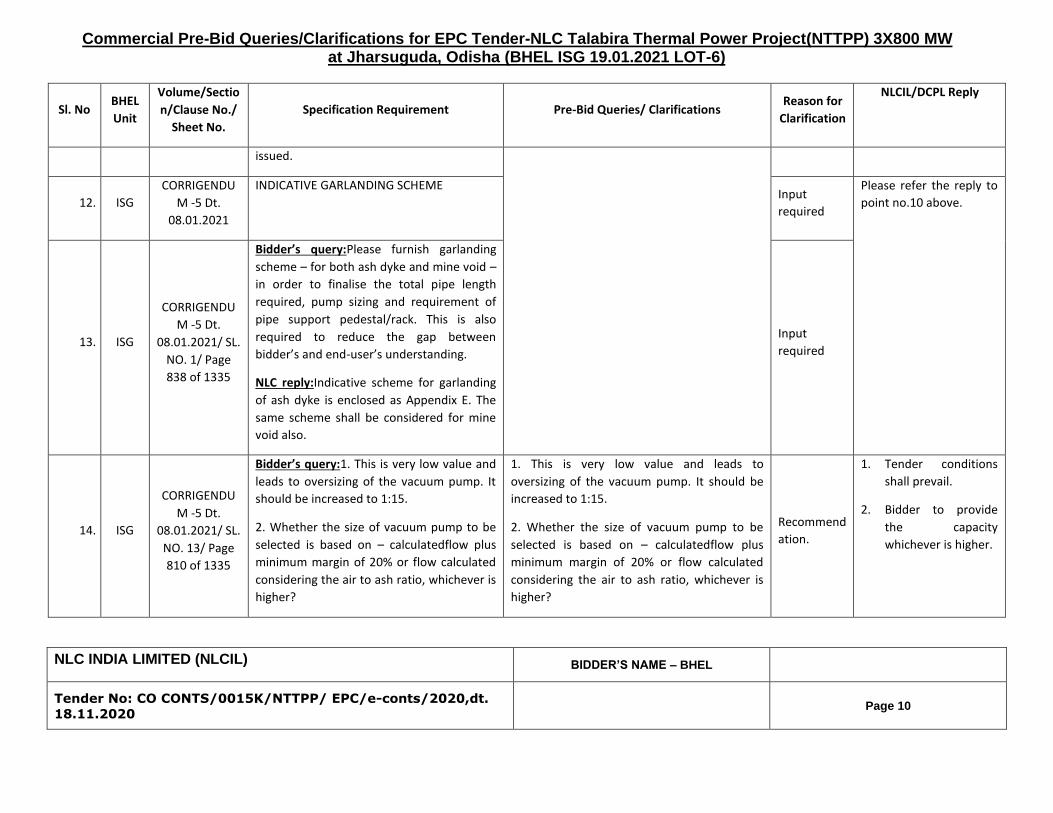
12. ISG
CORRIGENDU
M -5 Dt.
08.01.2021
INDICATIVE GARLANDING SCHEME Input
required
Please refer the reply to
point no.10 above.
13. ISG
CORRIGENDU
M -5 Dt.
08.01.2021/ SL.
NO. 1/ Page
838 of 1335
Bidder’s query:Please furnish garlanding
scheme – for both ash dyke and mine void –
in order to finalise the total pipe length
required, pump sizing and requirement of
pipe support pedestal/rack. This is also
required to reduce the gap between
bidder’s and end-user’s understanding.
NLC reply:Indicative scheme for garlanding
of ash dyke is enclosed as Appendix E. The
same scheme shall be considered for mine
void also.
Input
required
14. ISG
CORRIGENDU
M -5 Dt.
08.01.2021/ SL.
NO. 13/ Page
810 of 1335
Bidder’s query:1. This is very low value and
leads to oversizing of the vacuum pump. It
should be increased to 1:15.
2. Whether the size of vacuum pump to be
selected is based on – calculatedflow plus
minimum margin of 20% or flow calculated
considering the air to ash ratio, whichever is
higher?
1. This is very low value and leads to
oversizing of the vacuum pump. It should be
increased to 1:15.
2. Whether the size of vacuum pump to be
selected is based on – calculatedflow plus
minimum margin of 20% or flow calculated
considering the air to ash ratio, whichever is
higher?
Recommend
ation.
1. Tender conditions
shall prevail.
2. Bidder to provide
the capacity
whichever is higher.
Page 58 of 294

Commercial Pre-Bid Queries/Clarifications for EPC Tender-NLC Talabira Thermal Power Project(NTTPP) 3X800 MW at Jharsuguda, Odisha
NLC INDIA LIMITED (NLCIL) BIDDER’S NAME – BHEL
Tender No: CO CONTS/0015K/NTTPP/ EPC/e-conts/2020,dt.
18.11.2020 Page 1
Sl.
No
BHEL
Unit
Volume/Section/ Clause
No./ Sheet No. Specification Requirement
Pre-Bid Queries/
Clarifications NLCIL response
1. PEM Vol. II- G2/Part A/Section-
V/ Page 10 of 22/ 3.05.02
With Drilling Fluid A five per cent bentonite suspension would be generally suitable and its quality shall conform to specification given in Appendix 'A' of IS : 2911 (Part-I/Sec.2).
Bidder proposes to use Polymer fluid in place of bentonite suspension for stabilization of pile bore. Please confirm.
Technical
Specification
prevails
2. PEM
Corrigendum-5, Pre bid
replies, Appendix E, page
no. 1173 of 1336
In ash dyke, partition bund is introduced. Please furnish the cross section details of the partition bund i.e. height, top width, slope, earthen/RCC. Also please confirm the requirement of road and fencing on the top of partition bund.
Refer corrigendum 5
ANNEXURE – C2I ,
Sl.no 1
Page 65 of 294

Commercial Pre-Bid Queries/Clarifications for EPC Tender-NLC Talabira Thermal Power Project(NTTPP) 3X800 MW at Jharsuguda, Odisha
NLC INDIA LIMITED (NLCIL) BIDDER’S NAME – BHEL
Tender No: CO CONTS/0015K/NTTPP/ EPC/e-conts/2020,dt.
18.11.2020 Page 2
Sl.
No
BHEL
Unit
Volume/Section/ Clause
No./ Sheet No. Specification Requirement
Pre-Bid Queries/
Clarifications NLCIL response
3.
PEM Vol. II-H1 Ash Handling System/Section B/ Page
8 of 90/ 3.03.04
The capacity of each HCSD stream will
be envisaged around @ 212 TPH (dry ash basis) considering total Ash Generation at BMCR
Based on the referred
clauses, the area does not seem sufficient to meet the specification
requirement of storage capacity of 2 years.
Please review the
requirement of ash storage in ash dyke
and provide sufficient space.
Vol. II-H1
AHS/Section B/
Page 8 of 90/
3.03.04 is amended
as below.
High concentrated
ash slurry will be
disposed in the ash
dyke. About 150
acres of land is
identified for the
same. The height of
ash to be dumped in
the ash dyke shall
be about 8.5m and
will be constructed
on the area shown in
the Plot Plan.
The capacity of the
ash dyke shall be
arrived considering
ash generated while
burning worst coal at
100% TMCR from all
the three units at
85% PLF. The bulk
4.
PEM Vol. II-H1 Ash Handling System/Section B/ Page
10 of 90/ 3.03.20
The capacity of the ash dyke shall be such that it shall store the quantity of
ash generated from all the three units for two years ……
5.
PEM GA of ash dyke (18A03-DWG-C-0008) Rev 0
Dated 29.11.2020
Dyke Area: 175 Acre
Slurry Collection: 150 Acre
6. PEM
Sl. No. 30, 1.2 Section B: EPC, Table C: Civil of corrigendum -3 dated
18.12.2020
Ash dyke shall be constructed by optimized cutting/filling required to build
up storage capacity as indicated in Mechanical Volume. With top of the
bund shall not exceed 204.0 m including free board of 1.5 m and bottom level shall be kept above the ground water
table.
Page 66 of 294

Commercial Pre-Bid Queries/Clarifications for EPC Tender-NLC Talabira Thermal Power Project(NTTPP) 3X800 MW at Jharsuguda, Odisha
NLC INDIA LIMITED (NLCIL) BIDDER’S NAME – BHEL
Tender No: CO CONTS/0015K/NTTPP/ EPC/e-conts/2020,dt.
18.11.2020 Page 3
Sl.
No
BHEL
Unit
Volume/Section/ Clause
No./ Sheet No. Specification Requirement
Pre-Bid Queries/
Clarifications NLCIL response
density to be
considered for the
calculation of ash
dyke capacity shall
be 1.4t/m3.
7. PEM Plot Plan drawing no. 18A03-DWG-M-002A, Rev 1
In plot plan drawing, area for raw water reservoir is allocated as 92 acres. Effective storage capacity of Raw water reservoir is 34,56,000 cum. Accordingly; the area is not sufficient to cater the requirement of storage capacity.
Please increase the area allocated for raw water reservoir.
Bidder’s query/clarification is noted. Accordingly the relevant Clauses will be modified suitably.
8.
PEM
Vol. II-IB/1/Section-I/Page 2 of 14/2.01.09
Makeup water from Hirakud reservoir shall be pumped to the in-plant raw water reservoir with twin compartments having effective storage capacity of 34,56,000 cum. Raw water supply pumps located in raw water reservoir will feed to the pre-treatment plant for required clarification and emergency makeup to ash handling system..
Page 67 of 294

Sr. No. Section / Part /
Chapter / Volume
Clause No. Page no.
Bid Specification Stipulation Statement of clarification sought
NLCIL/DCPL
Reply vide
Corrigendum
No. 5
Statement of clarification sought 22.01.2021 Purchaser's Reply
Ash Handling Plant
1763 Corrigendum 5,
point no. 272,
Page 887 of
1335
SECTION-B
Vol. II-H1
Ash Handling
System
3.01.01
3.01.05
Page 4 of 90
Page 5 of 90
Bottom Ash System ... The effective
storage capacity of BA hopper shall be
minimum eight (8) hours Bottom ash,
Economizer ash and SCR ash generated
while firing worst coal measured upto 300
mm below maximum water level of the BA
hopper. Bottom ash shall be evacuated
once in a shift of 8 hours.
The bottom ash hopper associated
equipment shall be located above ground
for ease in maintenance. Jet pumps and
piping shall be above ground and pipeline
shall be on pedestals in Boiler area.
Further the pipes shall be routed on a pipe
rack.
Considering the higher ash generation rate at
BMCR worst coal & eight (8) hour bottom ash
hopper storage capacity, the size of bottom ash
hopper will be very large which would result in
changing the design of the boiler. Hence, bidder
requests five (5) hour bottom ash hopper
effective storage capacity considering bottom
ash cleaning twice in a shift of eight (8) hours, in
line with the latest industrial practice including
recent NTPC Projects.
Owner is requested to confirm the same.
Tender
conditions
prevail.
Bidder understands that Bottom Ash Hopper arrangement
inline to the 3x660 MW NLC Ghatampur Project is also
acceptable for 3x800 MW NLC Talabira Project.
Kindly confirm Bidder's understanding.
Tender conditions shall prevail.
Corrigendum 5,
point no. 278,
Page 889 of
1335
SECTION-B
Vol. II-H1
Ash Handling
System
3.03.06 Page 8 of 90 Combined HCSD slurry shall be disposed
in the mine void created in the Talabira
Mines-II&III which is located approximately
4 KM away from plant area. It is also
proposed to dispose the combined HCSD
slurry in the ash dyke during emergency
which is also located approx. 4KM from
the plant.
In absence of Clarity, Owner is requested to
specify the total pipe length of HCSD pipe for all
three units, which shall be in Bidder's Scope of
supply.
Please refer
the
Corrigendum
issued.
Larsen & Toubro Limited
EPC Power Business Unit
NLC INDIA LIMITED
NLC TALABIRA THERMAL POWER PROJECT
3x800 MW, JHARSUGUDA, ODISHA
(EPC Bidding Document)
1. The static lift and pumping distance
to be considered for HCSD pumping
design are 40 meters and 7000 meters
excluding garlanding.
2. Each discharge line from the pump
house to mines & ash dyke shall be
7000m and 4000m respectively
excluding fittings.
In addition, 10000m pipe shall be
considered for garlanding each for
mines and dyke respectively excluding
fittings & including raiser branch pipes
for discharge o ash dyke. Garlanding
scheme shall be as per the indicative
scheme provided in the Corrigendum-
5.
1764 As per corrigendum No. 3, Combined HCSD slurry shall be
disposed in the mine void created in the Talabira Mines-II&III
which is located approximately 7 KM away from plant area. It
is also proposed to dispose the combined HCSD slurry in the
ash dyke during emergency which is also located approx.
4KM from the plant.
As per corrigendum No. 5, Indicative scheme for garlanding
of ash dyke is enclosed as Appendix E . The same scheme
shall be considered for mine void also.
Owner to note that in both corrigendums, Maximum route
length (including applicable garlanding length) for HCSD
design and supply length for HCSD Pipe are not specified.
In absence of inputs, Owner is requested to confirm the
following:
1) Mine void for Talabira Mines-II&III is a combined void.
2) Garlanding scheme and piping length for Garlanding in
Mine-II & III shall be identical to Ash Dyke and it will be as
per Appendix E.
3) For Mine-II & III: Maximum route length for HCSD pump
design shall be 7 KM from HCSD pump house to start of
Mine-II & III + Garlanding length derived from Appendix E
(Garlanding Scheme for Ash Dyke).
4) For Ash Dyke: Maximum route length for HCSD pump
design shall be 4 KM from HCSD pump house to start of Ash
Dyke + Garlanding length derived from Appendix E
(Garlanding Scheme for Ash Dyke).
Technical (Lot-4_ 22nd Jan 2020) Page1 of 13Page 106 of 294
Sr. No. Section / Part /
Chapter / Volume
Clause No. Page no.
Bid Specification Stipulation Statement of clarification sought
NLCIL/DCPL
Reply vide
Corrigendum
No. 5
Statement of clarification sought 22.01.2021 Purchaser's Reply
Larsen & Toubro Limited
EPC Power Business Unit
NLC INDIA LIMITED
NLC TALABIRA THERMAL POWER PROJECT
3x800 MW, JHARSUGUDA, ODISHA
(EPC Bidding Document)
Corrigendum 5,
point no. 279,
Page 890 of
1335
SECTION-B
Vol. II-H1
Ash Handling
System
3.03.04
3.03.06
3.08.39
5.34.00
Page 8 of 90
Page 8 of 90
Page 16 of 90
Page 68 of 90
The capacity of each HCSD stream will be
envisaged around @ 212 TPH (dry ash
basis) considering total Ash Generation at
BMCR for one (1) unit with ash
concentration in disposed slurry as 55% to
65%. However, Bidder shall revalidate the
ash concentration % in HCSD system with
ash slurry rheology test.
Combined HCSD slurry shall be disposed
in the mine void created in the Talabira
Mines-II&III which is located approximately
4 KM away from plant area. It is also
proposed to dispose the combined HCSD
slurry in the ash dyke during emergency
which is also located approx. 4KM from
the plant.
One (1) set of HCSD slurry disposal pipe
emerging out from each HCSD pump,
covering a distance of approximately 4.0
kilometers from Silo utility
building cum HCSD pump house with a
static lift of approximate 40 meter up to
ash disposal area ie either in the mine
void area of Talabira mines-II&III or in the
emergency ash dyke with independent
In absence of clarity, Bidder understand that
following parameter shall be consider to finalize
the HSCD pump parameter:
1. Maximum Pumping Distance : 4 km
2. Static Lift : 40 m
3. Design concentration : 60 % (W/W)
Owner is requested to confirm Bidder's
understanding.
Please refer
the
Corrigendum
issued.
Corrigendum 5,
point no. 1466,
Page 1043 of
1335
Plot Plan 18A03-
DWG-M-002A
Diversion of HCSD slurry pipes to mines is
after crossing the Bhedan Bridge
Since the diversion of HCSD slurry pipes to
mines is after crossing the Bhedan Bridge, the
route length for HCSD design may be different
for Ash Dyke and Mines. Maximum route length
(including applicable garlanding length) for
HCSD design may please be defined. HCSD
Pipe supply length also needs to be defined.
Please refer
the
corrigendum-
3 issued.
1. The static lift and pumping distance
to be considered for HCSD pumping
design are 40 meters and 7000 meters
excluding garlanding.
2. Each discharge line from the pump
house to mines & ash dyke shall be
7000m and 4000m respectively
excluding fittings.
In addition, 10000m pipe shall be
considered for garlanding each for
mines and dyke respectively excluding
fittings & including raiser branch pipes
for discharge o ash dyke. Garlanding
scheme shall be as per the indicative
scheme provided in the Corrigendum-
5.
1764 As per corrigendum No. 3, Combined HCSD slurry shall be
disposed in the mine void created in the Talabira Mines-II&III
which is located approximately 7 KM away from plant area. It
is also proposed to dispose the combined HCSD slurry in the
ash dyke during emergency which is also located approx.
4KM from the plant.
As per corrigendum No. 5, Indicative scheme for garlanding
of ash dyke is enclosed as Appendix E . The same scheme
shall be considered for mine void also.
Owner to note that in both corrigendums, Maximum route
length (including applicable garlanding length) for HCSD
design and supply length for HCSD Pipe are not specified.
In absence of inputs, Owner is requested to confirm the
following:
1) Mine void for Talabira Mines-II&III is a combined void.
2) Garlanding scheme and piping length for Garlanding in
Mine-II & III shall be identical to Ash Dyke and it will be as
per Appendix E.
3) For Mine-II & III: Maximum route length for HCSD pump
design shall be 7 KM from HCSD pump house to start of
Mine-II & III + Garlanding length derived from Appendix E
(Garlanding Scheme for Ash Dyke).
4) For Ash Dyke: Maximum route length for HCSD pump
design shall be 4 KM from HCSD pump house to start of Ash
Dyke + Garlanding length derived from Appendix E
(Garlanding Scheme for Ash Dyke).
Technical (Lot-4_ 22nd Jan 2020) Page2 of 13Page 107 of 294
Sr. No. Section / Part /
Chapter / Volume
Clause No. Page no.
Bid Specification Stipulation Statement of clarification sought
NLCIL/DCPL
Reply vide
Corrigendum
No. 5
Statement of clarification sought 22.01.2021 Purchaser's Reply
Larsen & Toubro Limited
EPC Power Business Unit
NLC INDIA LIMITED
NLC TALABIRA THERMAL POWER PROJECT
3x800 MW, JHARSUGUDA, ODISHA
(EPC Bidding Document)
Corrigendum 5,
point no. 1,
Page 838 of
1335
CORRIGENDUM
-3 Dt.
18.12.2020/ Plan
No.009/SUR/TAL
A-II&III,2019
Tentative route of the high concentration
slurry disposal pipe on the pedestals/pipe
rack from Silo utility building cum HCSD
pump house upto the bridge with
approach road as planned on Bhedan
river and ash slurry pipelines has been
shown in Plot Plan (Drawing No. 18A03-
DWG-M-002A). However, Bidder to
arrange detail survey of High
Concentration Slurry Disposal pipe
corridor in totality from Silo utility building
cum HCSD pump house up to the
proposed HCSD slurry disposal areas.
Laying of the twelve (12) HCSD slurry
pipes (for three nos. present units),
fittings, valves, couplings, instruments etc.
along with construction of supporting
pedestals and thrust blocks etc. for
successful completion of the system in all
respect upto ash dyke and mine void area
shall be in the scope of the Bidder. Bidder
to consider Pipe rack / pipe bridge with 8.0
m road clearance for road / rail crossing
throughout the entire pipe route, if any.
Height of pipe pedestals shall be minimum
1000 mm from FGL.
Please furnish garlanding scheme – for both ash
dyke and mine void – in order to finalise the total
pipe length required, pump sizing and
requirement of pipe support pedestal/rack. This
is also required to reduce the gap between
bidder’s and end-user’s understanding.
Indicative
scheme for
garlanding of
ash dyke is
enclosed as
Appendix E .
The same
scheme shall
be
considered
for mine void
also.
Corrigendum 5,
point no. 313,
Page 896 of
1335
SECTION-B
Vol. II-H1
Ash Handling
System
3.03.20 Page 10 of 90 Combined High concentrated ash slurry
will be disposed in the slurry disposal area
ie either in the ash dyke or in the mine
void area of Talabira Mines-II&III.
Owner is requested to provide Area map of the
Mine void to work on the slurry pipe garlanding.
Please refer
the
Corrigendum
issued.
1. The static lift and pumping distance
to be considered for HCSD pumping
design are 40 meters and 7000 meters
excluding garlanding.
2. Each discharge line from the pump
house to mines & ash dyke shall be
7000m and 4000m respectively
excluding fittings.
In addition, 10000m pipe shall be
considered for garlanding each for
mines and dyke respectively excluding
fittings & including raiser branch pipes
for discharge o ash dyke. Garlanding
scheme shall be as per the indicative
scheme provided in the Corrigendum-
5.
1764 As per corrigendum No. 3, Combined HCSD slurry shall be
disposed in the mine void created in the Talabira Mines-II&III
which is located approximately 7 KM away from plant area. It
is also proposed to dispose the combined HCSD slurry in the
ash dyke during emergency which is also located approx.
4KM from the plant.
As per corrigendum No. 5, Indicative scheme for garlanding
of ash dyke is enclosed as Appendix E . The same scheme
shall be considered for mine void also.
Owner to note that in both corrigendums, Maximum route
length (including applicable garlanding length) for HCSD
design and supply length for HCSD Pipe are not specified.
In absence of inputs, Owner is requested to confirm the
following:
1) Mine void for Talabira Mines-II&III is a combined void.
2) Garlanding scheme and piping length for Garlanding in
Mine-II & III shall be identical to Ash Dyke and it will be as
per Appendix E.
3) For Mine-II & III: Maximum route length for HCSD pump
design shall be 7 KM from HCSD pump house to start of
Mine-II & III + Garlanding length derived from Appendix E
(Garlanding Scheme for Ash Dyke).
4) For Ash Dyke: Maximum route length for HCSD pump
design shall be 4 KM from HCSD pump house to start of Ash
Dyke + Garlanding length derived from Appendix E
(Garlanding Scheme for Ash Dyke).
Technical (Lot-4_ 22nd Jan 2020) Page3 of 13Page 108 of 294

Sr. No. Section / Part /
Chapter / Volume
Clause No. Page no.
Bid Specification Stipulation Statement of clarification sought
NLCIL/DCPL
Reply vide
Corrigendum
No. 5
Statement of clarification sought 22.01.2021 Purchaser's Reply
Larsen & Toubro Limited
EPC Power Business Unit
NLC INDIA LIMITED
NLC TALABIRA THERMAL POWER PROJECT
3x800 MW, JHARSUGUDA, ODISHA
(EPC Bidding Document)
Corrigendum 5,
point no. 279,
Page 893 of
1335
SECTION-B
Vol. II-H1
Ash Handling
System
3.03.04
3.03.06
3.08.39
5.34.00
Page 8 of 90
Page 8 of 90
Page 16 of 90
Page 68 of 90
The capacity of each HCSD stream will be
envisaged around @ 212 TPH (dry ash
basis) considering total Ash Generation at
BMCR for one (1) unit with ash
concentration in disposed slurry as 55% to
65%. However, Bidder shall revalidate the
ash concentration % in HCSD system with
ash slurry rheology test.
Combined HCSD slurry shall be disposed
in the mine void created in the Talabira
Mines-II&III which is located approximately
4 KM away from plant area. It is also
proposed to dispose the combined HCSD
slurry in the ash dyke during emergency
which is also located approx. 4KM from
the plant.
One (1) set of HCSD slurry disposal pipe
emerging out from each HCSD pump,
covering a distance of approximately 4.0
kilometers from Silo utility
building cum HCSD pump house with a
static lift of approximate 40 meter up to
ash disposal area ie either in the mine
void area of Talabira mines-II&III or in the
emergency ash dyke with independent
In absence of clarity, Bidder understand that
following parameter shall be consider to finalize
the HSCD pump parameter:
1. Maximum Pumping Distance : 4 km
2. Static Lift : 40 m
3. Design concentration : 60 % (W/W)
Owner is requested to confirm Bidder's
understanding.
Please refer
the
Corrigendum
issued.
Owner is requested recheck the Maximum surface elevation
of the mine dump area as 286M which seems to be on
higher side for HCSD pump design.
Corrigendum 5,
point no. 1468,
Page 1043 of
1335
Vol. II-H1
Ash Handling
System
5.34.07 (E)
(iv)
… additional static lift of 40 metre at
disposal area …... along with the static
head difference between silo area and
mine dump area.
Static head difference between silo area and
mine dump area may please be specified.
Maximum
surface
elevation of
the mine
dump area
shall be
considered
as 286M.
The Maximum surface elevation of the
mine dump area as per Corrigendum-3
shall be taken as 211M.
1765
Technical (Lot-4_ 22nd Jan 2020) Page4 of 13Page 109 of 294
Sr. No. Section / Part /
Chapter / Volume
Clause No. Page no.
Bid Specification Stipulation Statement of clarification sought
NLCIL/DCPL
Reply vide
Corrigendum
No. 5
Statement of clarification sought 22.01.2021 Purchaser's Reply
Larsen & Toubro Limited
EPC Power Business Unit
NLC INDIA LIMITED
NLC TALABIRA THERMAL POWER PROJECT
3x800 MW, JHARSUGUDA, ODISHA
(EPC Bidding Document)
1768 Corrigendum 5,
point no. 281,
Page 890 of
1335
SECTION-B
Vol. II-H1
Ash Handling
System
Corrigendum No.
6 Point No. 43,
page 32 of 112
3.03.20
Lot 4 of BHEL
PBQ, Sr. No.
43.
Page 10 of 90
Page No. 20
Combined High concentrated .... The
capacity of the ash dyke shall be such that
it shall store the quantity of ash generated
from all the three units for two years
The capacity of each HCSD stream will be
envisaged around @ ... for two years ……
In absence of input, request owner to please
furnish following design basis for ash pond
storage volume calculation:-
i) Plant operating condition (whether 100%
TMCR or BMCR)
ii) Type of coal (whether worst coal or design
coal)
iii) Placed density of ash to be considered for
ash pond storage sizing
iv) Ash distribution for each year (Bottom ash
and Fly ash) considering the fly ash utilization
philosophy.
The capacity of each HCSD stream will be
envisaged around @ 212 TPH (dry ash basis)
considering total Ash Generation at BMCR
The capacity of the ash dyke shall be such that it
shall store the quantity of ash generated from all
the three units for two years ……
i) 100%
TMCR
ii) Worst coal
iii) 1.4 t/m3
iv) 100% BA
& FA.
Based on the
ash
generation
capacity
furnished in
the
specification
(212
TPH/Boiler),
required Ash
dyke
capacity
shall be =
(212*24*365
*3*0.8*2)/1.4
= 6367269
cum
Owner to note that in corrigendum No. 6
(Lot 4 of BHEL PBQ, Sr. No. 43.) Page No. 20, Owner reply
is that tender condition prevail for ash storage volume for
calculation of Ash pond.
In this regard, Bidder understands that Ash pond volume
shall be calculated inline with below input:
i) 100% TMCR
ii) Worst coal
iii) 1.4 t/m3
iv) 100% BA & FA.
v) PLF 85% as per clause No. 5.00.00 FUEL of Vol. II-
A/Section-III Project Synopsis & General Information.
Owner is requested to please confirm Bidder understanding.
Bidder understanding is correct.
1769 SECTION-B
Vol. II-B/Section-I
Steam Generator
& Accessories
Vol. II-B/Section-
II
Electrostatic
Precipitator
ANNEXURE-I
SPECIFIC
DESIGN
CRITERIA
FOR STEAM
GENERATOR
AND
AUXILIARIES
- Sl. NO.
5.20.b
Annexure-I
SPECIFIC
DESIGN
CRITERIA
FOR
ELECTROST
ATIC
PRECIPITAT
OR SIZING
Sl. No. 13 m
Page 120 of
122
Page 24 of 25
b) Elevation of lowest ash hopper outlet
flange from ground / platform level :
Minimum 3.5 meters
Height of the lowest ash hopper outlet
flange from ground level : Minimum 3.5 M.
Bidder to assure minimum 2.5 m
headroom for ash dumping in trucks in
case of ESP failure. ESP structure /
bracing should be such as to enable truck
entry. Also ESP hoppers shall have
additional blanked spout for such
emergency ash unloading.
Owner is requested to note that Elevation of
Economisers, SCR inlet duct, Air Heaters, ESP
Hoppers shall be provided by the Boiler/ESP
OEM and same shall be followed by AHP
supplier.
Owner is requested to confirm the same.
However to accommodate vacuum conveying
system below ESP hopper, bottom flange
dimension shall be provided by ESP OEM which
shall be followed by the AHP supplier and
accordingly headroom below ESP hopper shall
be finalized.
Owner is requested to confirm the same.
Tender
conditions
prevail.
Owner to note that headroom for ash dumping in trucks in
case of ESP failure shall be decided based on system
requirement of ESP & AHP. Hence, the minimum 2.5 m
headroom shall not be applicable for ash dumping in trucks.
Please confirm acceptance.
Tender conditions shall prevail.
Technical (Lot-4_ 22nd Jan 2020) Page6 of 13Page 111 of 294
1821 Corrigendum 5
Query Serial No. 1307
Geotechnical Investigation
Vol. II-G1/ Section V
1.02.00 1026 of 1335 The design, type, size, depth of the foundation/pile, Net safe bearing
capacity/pile capacity values shall be based on the approved soil
investigation report of the successful Bidder/Owner’s soil
recommendations (Available in the Tender document) whichever is
conservative.
The design, type, size, depth of
the foundation/pile, Net safe
bearing capacity/pile capacity
values shall be based on the
approved soil investigation report
of the successful Bidder/Owner’s
soil recommendations, kindly
confirm.
Available Geotechnical
investigation report is already
uploaded. However conservative
value of the nearest borehole as
per the discretion of Owner /
Consultant shall be binding upon
the successful bidder.
Owner to note that the Ground level mentioned in the bore hole report do not match with the contour
levels shared with the tender document. Comparison of the same is attached as Annexure-1 for your
reference.
As not a single bore hole is available for facilities like FGD, Switchyard, ETP, DM etc., hence it will not be
possible to interpret soil parameters from tender stage geotechnical investigation report.
Owner to kindly review and accept Bidder's submission that approved soil investigation report will be
considered during detail engineering.
Soil report enclosed shall be followed as such
with figures indicated against RL shall be
replaced with NGL. The NGL (RL) of the Bore
level shall be taken from the Talabira contour
levels.
Tender condition prevails. For clarity,
Conservative value of the nearest borehole as
per the discretion of Owner / Consultant shall be
binding upon the successful bidder.
1822 Section-II/Vol. II-G1 4.00.00
(d)
17 of 38 The design of R.C.C - Structures shall be carried out by limit state or
working stress method as per the provisions of IS-456 (Latest
Revision).
As per standard practice RCC
shall be designed as per limit
state method as per IS 456 :
2000. Please confirm.
Tender condition prevails The clarification given by customer is not clear to us. IS 456 : 2000 refers to RCC structure design as per
limit state method only. In case customer requires for working stress method using the above mentioned
code, the specific structures requiring such designs may please be clarified.
Tender condition prevails. For clarity, Working
stress method using IS 456 : 2000 shall be
followed wherever mentioned in the
specification. Otherwise limit state method shall
be followed for all other structures.
1823 Section-IV/Vol. II-G1 3.19.00
(g)
43 of 127 Suitable arrangement of floor drain with trap shall be provided in
floor where spillage of water / floor washing will occur.
As a matter of practice followed in
every plant, drains are not
considered on the elevated RCC
floors of the steel buildings. This
wash water is drained towards the
down comer pipes located at
suitable corners of the buildings
through floor slope of 1 in 200.
However for roof this slope is
envisaged to be 1 in 100.
Tender condition prevails As a matter of practice followed in every plant, drains are not considered on the elevated RCC floors of
the steel buildings. This wash water is drained towards the down comer pipes located at suitable corners
of the buildings through floor slope of 1 in 200. However for roof this slope is envisaged to be 1 in 100.
Owner is once again requested to review the specific requirement in the clause and revert back.
For elevated floors, drains are not necessary.
Floor drainage arragement shall be provided
with necessary slope and trap in floor where
spillage of water / floor washing will occur.
1824 Vol. II-G1/Section-I
Corrigendum 3
Corrigendum 6
4.23.10
Point 30
Point 43
34 of 40
32 of 112
Ash dyke shall be constructed by optimized cutting/filling required to
build up storage capacity as indicated in Mechanical Volume. With
top of the bund shall not exceed 204.0m including free board of 1.5
m and bottom level shall be kept above the ground water table.
Request Owner to provide the site specific Ground Water Table level to verify the ash storage volume
with respect to the allotted area and bund height RL as 204.0M.
Also Owner to advise measures in case the storage volume within the specified boundary conditions
does not meet the specified capacity requirement.
(As per geotechnical report provided in tender, for Borehole 29, Standing Water Level was observed as
198.225)
Soil investigation for Ash dyke is Under bidders
scope.
For capacity refer Mechanical volume
1825 Vol II-G1
Corrigendum 3
4.25.02
Point 38 34 of 40
The reservoir shall be formed with optimum cutting and filling of the
earth (without compromising the safety of power plant) with top of
the bund shall not exceed 204.0m including free board of 1.5 m and
bottom level shall be kept above the ground water table.
Request Owner to provide the site specific Ground Water Table level to verify the raw water storage
volume with respect to the allotted area and bund height RL as 204.0M.
Also Owner to advise measures in case the storage volume within the specified boundary conditions
does not meet the specified capacity requirement.
(As per geotechnical report provided in tender, for Borehole 21, Standing Water Level was observed as
196.601)
For RWR holding capacity calculations only - Ground
water table shall be considered at RL 194.00 m , this
reply shall read in conjunction with reply 1821.
Necessary dewatering if any shall be considered
during constrction based on actual site condition as
water table fluctuates throughout the year.
For capacity refer Mechanical volume
1826 Vol II-G1/Section-1
Corrigendum 5
sr. no. 477)
4.21.04 38 of 118 Run-off coefficient for open ground area (unpaved) shall be
minimum 0.90 and for paved area and other covered surface
including roads the same shall be considered as 1.0.
Please note, as per IRC:SP:42-2014, Table 6.5, the run-off coefficient for 'Steep, bare rock and
watertight pavement surface
(concrete or bitumen)' shall be 0.9 and for unpaved areas shall be 0.5 to 0.6. Bidder requests Owner to
consider the values indicated above to get realistic drain design/ cross sections
Run-off coefficient for open ground area
(unpaved) shall be minimum 0.75 and for paved
area and other covered surface including roads
the same shall be considered as 0.9.
1827 Drawing B1, Corrigendum 6
Rain water harvesting pond:
All the rain water from road rains/ buildings
shall be conveyed and let into Rain
harvesting pond
1. Please furnish the storm water outfall points for
a) Plant storm water drains
b) Peripheral single lane road (at NGL), main plant approach road, peripheral double lane road (Marked
in green colour in area grading drawing B1-R1)
c) Approach roads from township
2. The rain water harvesting pond (40,000 Cum) is not capable of holding the entire plant catchment
water. Please confirm size of pond.
1. a.Will be conncted to rainwater harvestinng
pond for Inside Plant boundary only.
2.For capacity of Rain water harvesting pond
tender condition prevails .For clarity, water from
the RWHP shall be pumped into the Raw water
resevoir and to ensure that there is no overflow
from RWHP.
1830 Vol II-G1 4.23.10
4.25.02 34 of 40
Ash Dyke and Raw water Reservoir embankments of height less than 3.0M do not require sand chimney
and rock toe as per Table 1, IS 12169. Please confirm it is not required for both the facilities.
Tender condition prevails
Technical (Lot-4_ 22nd Jan 2020) Page2 of 4Page 124 of 294

Page 128 of 294
Pre-Bid Queries/Clarifications for EPC Tender-NLC Talabira Thermal Power Project(NTTPP) 3X800 MW at Jharsuguda, Odisha _ From L & T
Sl. No Bidder Query
Ref. Pre-Bid Queries/ Clarifications NLCIL / DCPL Reply
21/18
Dated 16/02/2021
S.No 14
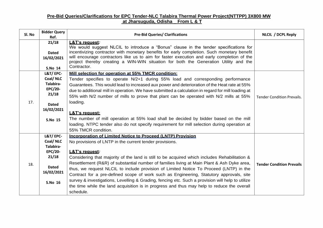
L&T’s request: We would suggest NLCIL to introduce a “Bonus” clause in the tender specifications for incentivizing contractor with monetary benefits for early completion. Such monetary benefit will encourage contractors like us to aim for faster execution and early completion of the project thereby creating a WIN-WIN situation for both the Generation Utility and the Contractor.
17.
L&T/ EPC-Coal/ NLC Talabira-EPC/20-21/18
Dated
16/02/2021
S.No 15
Mill selection for operation at 55% TMCR condition:
Tender specifies to operate N/2+1 during 55% load and corresponding performance
Guarantees. This would lead to increased aux power and deterioration of the Heat rate at 55%
due to additional mill in operation. We have submitted a calculation in regard for mill loading at
55% with N/2 number of mills to prove that plant can be operated with N/2 mills at 55%
loading.
L&T’s request:
The number of mill operation at 55% load shall be decided by bidder based on the mill
loading. NTPC tender also do not specify requirement for mill selection during operation at
55% TMCR condition.
Tender Condition Prevails.
18.
L&T/ EPC-Coal/ NLC Talabira-EPC/20-21/18
Dated
16/02/2021
S.No 16
Incorporation of Limited Notice to Proceed (LNTP) Provision
No provisions of LNTP in the current tender provisions.
L&T’s request:
Considering that majority of the land is still to be acquired which includes Rehabilitation &
Resettlement (R&R) of substantial number of families living at Main Plant & Ash Dyke area,
thus, we request NLCIL to include provision of Limited Notice To Proceed (LNTP) in the
Contract for a pre-defined scope of work such as Engineering, Statutory approvals, site
survey & investigations, Levelling & Grading, fencing etc. Such a provision will help to utilize
the time while the land acquisition is in progress and thus may help to reduce the overall
schedule.
Tender Condition Prevails
Page 159 of 294

BHEL PSSR SCT 1948 Corrigendum 1
Enclosure 2 to Corrigendum 1 dated March 12, 2021
to Tender Specification BHEL PSSR SCT 1948
AREA DRAINAGE STUDY FOR NLC TALABIRA THERMAL POWER PROJECT, STAGE I (3X800 MW)
(54 pages)
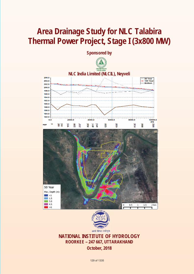
Area Drainage Study for NLC Talabira Thermal Power Project, Stage I (3x800 MW)
Sponsored by
NLC India Limited (NLCIL), Neyveli
NATIONAL INSTITUTE OF HYDROLOGY
ROORKEE – 247 667, UTTARAKHAND October, 2018
129 of 1335

i
Area Drainage Study for NLC Talabira Thermal
Power Project, Stage I (3x800 MW)
Study Group
J. P. Patra, Scientist C & PI
Rakesh Kumar, Scientist G & Head SWHD
Pankaj Mani, Scientist E
R. P. Pandey, Scientist G
NATIONAL INSTITUTE OF HYDROLOGY, ROORKEE – 247 667
130 of 1335
ii
EExecutive Summary NLC India Ltd (NLCIL) formerly, Neyveli Lignite Corporation Limited, a Navaratna
enterprise of Government of India (GoI) is an existing, profit making, public sector
enterprise engaged in mining of lignite and generation of power through lignite based
thermal power plants. Now, NLCIL is planning to implement a 3200 MW NLC Talabira
TPP in 2 Stages (Stage-I - 3x800 MW and Stage-II – 1x800 MW at a later date) with
linkage to Talabira-II & III captive coal blocks allocated to NLCIL, which are situated in
very close proximity to the project site. The project site is located near Kumbhari and
Tareikela villages on south west of Brijraj Nagar town on Sambalpur Rourkela highway in
Jharsuguda district. The geographical extent of the proposed project area lies along both
banks of Bhedan river, which is a tributary of IB river. The study envisages identification
of various flooding sources, estimation of maximum floods and their routing to the plant
site for estimating the maximum flood level. Further, this study also includes analysis of
local drainage pattern and final disposal point for the storm water and plant drainage.
The Digital Elevation Model (DEM) of the study area is prepared from surveyed contour
for the plant area, spot heights; contours digitized from the SOI toposheets and SRTM
data. The basin boundary and river networks are delineated from the DEM using HEC-
GeoHMS and various catchment characteristics are estimated. The catchment area of
Bhedan river at proposed plant site is about 3185.5 km2. Synthetic Unit Hydrograph is
developed using the catchment characteristics and following the guideline given in Flood
Estimation Report. Daily rainfall data of ten raingauge stations in and around the
catchment are procured from IMD, Pune and the annual 1-day maximum rainfall series are
extracted for rainfall frequency analysis. Regional rainfall frequency analysis using L-
moments approach is carried out for estimating rainfall of various return periods. The
robust frequency distribution among twelve frequency distribution is identified based on
L-moments ratio diagram and Zi dist –statistic criteria. Generalized Extreme Value (GEV)
is identified as the robust frequency distribution for this case. The 1-day annual maximum
rainfall for 25 year, 50 year and 100 year return periods are estimated to be 27.25 cm,
31.04 cm and 34.86 cm respectively. The design flood hydrograph are developed by
convoluting the SUH with estimated hourly incremental design rainfall. The peak floods in
131 of 1335
iii
Bhedan river due 50 year and 100 year return period flood are estimated to be 9956.07
m3/s and 11278.65 m3/s respectively.
The flood routing study has been carried out using MIKE FLOOD package (a coupled 1D
and 2-D flow analysis). The bathymetry of the flood plain around the plant site has been
created from the DEM. The spills from catchment drainage and local rainfall have been
simulated in MIKE-21. The 1-D model in Mike 11 is prepared for the study reach of
Bhedan river using surveyed river cross-section at fifteen locations and 2-D model in Mike
21 is developed for both main plant area and ash pond area using 10m cell size. Under pre-
project condition the maximum water level in the river varies from 201.5 m to 199 m along
the river stretch from cross-section 3 to cross-section 13 for 50 year return period flood.
The flood levels are estimated to be about 0.4 m higher in case of 100 year return period
flood. The potential source of flooding at the plant site can be due to the flooding from
Bhedan rive in the areas below RL202 m level. As a protection measure, construction of
embankments on both left and right bank is also analysed for various return period floods.
It is suggested that embankment is to be constructed on both banks, as construction of
embankments only in right bank (main plant area) will not be able to protect the ash pond
area. However, instead of creating embankment along the left bank of river, selective
protection to only ash dyke can be made as per requirement. The water level in river with
proposed embankment varies from 203.1 m to 200.6 m along the river reach form CS3 to
CS 13 for 100 year return period flood. It is also observed that at present embankment of
different stretches along the right bank are not flooded in the modelling study. However,
the embankment is not continuous and need to be strengthened. It is observed that the main
plant area has negligible flow from the upstream area and can be easily diverted along the
plan boundary/ periphery road. However, two natural stream/nall are flowing in and
around the ash pond area flowing from east (from Bhushan plant) to west and joins Bhedan
river. The drain in the north of proposed ash pond area of NLCIL will not interfere with
the proposed ash pond area of NLCIL. The other drain (D2) passes through the proposed
ash pond area of NLCIL and joins to Bhedan river. Two alternatives for the drain D2 are
analysed. The first alternative is to leave the alignment of drain D2 as it is, dividing the ash
pond area in two portions and area north of drain may be used for fly ash pond and area
south of drain may be used for bottom ash pond. In this case there will be very little
132 of 1335
iv
modification in the present alignment of the drain as the drain may be straightened and
strengthened with capacity in the area between the fly ash pond and bottom ash pond.
However, the drain caries discharge from Bhushan plant area including discharge from
iron ore washing plant etc. Hence it will be difficult for controlling water quality in the
drain section where it passes through the ash pond area. As second alternative, it is
proposed to divert the drain along the boundary of ash pond area in by diverting to first
south and then west direction. However, it is to be noted that in two stretches the cutting
would be in the range of about 8 m to maintain bed slope of drain. The estimated peak
runoff in the drain for 50 year and 100 year return period are 55.5 m3/s and 61.3 m3/s. Both
unlined trapezoidal section with a side slope of 1.5:1 (H:V) and lined rectangular section
drains are designed for longitudinal slope of 0.0015 m/m (1.5 m/km) to carry the estimated
runoff.
133 of 1335
National Institute of Hydrology, Roorkee 2
22 DESCRIPTION OF STUDY AREA
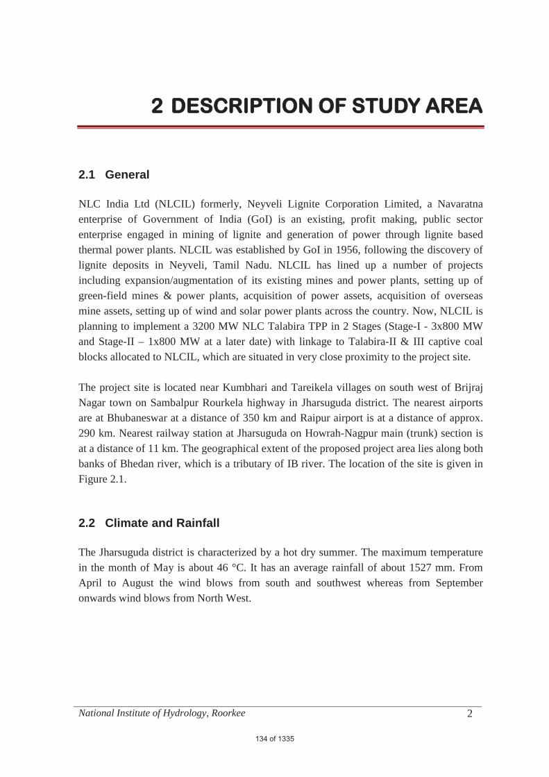
2.1 General NLC India Ltd (NLCIL) formerly, Neyveli Lignite Corporation Limited, a Navaratna enterprise of Government of India (GoI) is an existing, profit making, public sector enterprise engaged in mining of lignite and generation of power through lignite based thermal power plants. NLCIL was established by GoI in 1956, following the discovery of lignite deposits in Neyveli, Tamil Nadu. NLCIL has lined up a number of projects including expansion/augmentation of its existing mines and power plants, setting up of green-field mines & power plants, acquisition of power assets, acquisition of overseas mine assets, setting up of wind and solar power plants across the country. Now, NLCIL is planning to implement a 3200 MW NLC Talabira TPP in 2 Stages (Stage-I - 3x800 MW and Stage-II – 1x800 MW at a later date) with linkage to Talabira-II & III captive coal blocks allocated to NLCIL, which are situated in very close proximity to the project site. The project site is located near Kumbhari and Tareikela villages on south west of Brijraj Nagar town on Sambalpur Rourkela highway in Jharsuguda district. The nearest airports are at Bhubaneswar at a distance of 350 km and Raipur airport is at a distance of approx. 290 km. Nearest railway station at Jharsuguda on Howrah-Nagpur main (trunk) section is at a distance of 11 km. The geographical extent of the proposed project area lies along both banks of Bhedan river, which is a tributary of IB river. The location of the site is given in Figure 2.1. 2.2 Climate and Rainfall
The Jharsuguda district is characterized by a hot dry summer. The maximum temperature in the month of May is about 46 °C. It has an average rainfall of about 1527 mm. From April to August the wind blows from south and southwest whereas from September onwards wind blows from North West.
134 of 1335
Area Drainage Study for NLC Talabira Thermal Power Project
National Institute of Hydrology, Roorkee 3
Figure 2.1: Index map of the study Area
Plant area
Bridge on Bhedan river
135 of 1335
Area Drainage Study for NLC Talabira Thermal Power Project
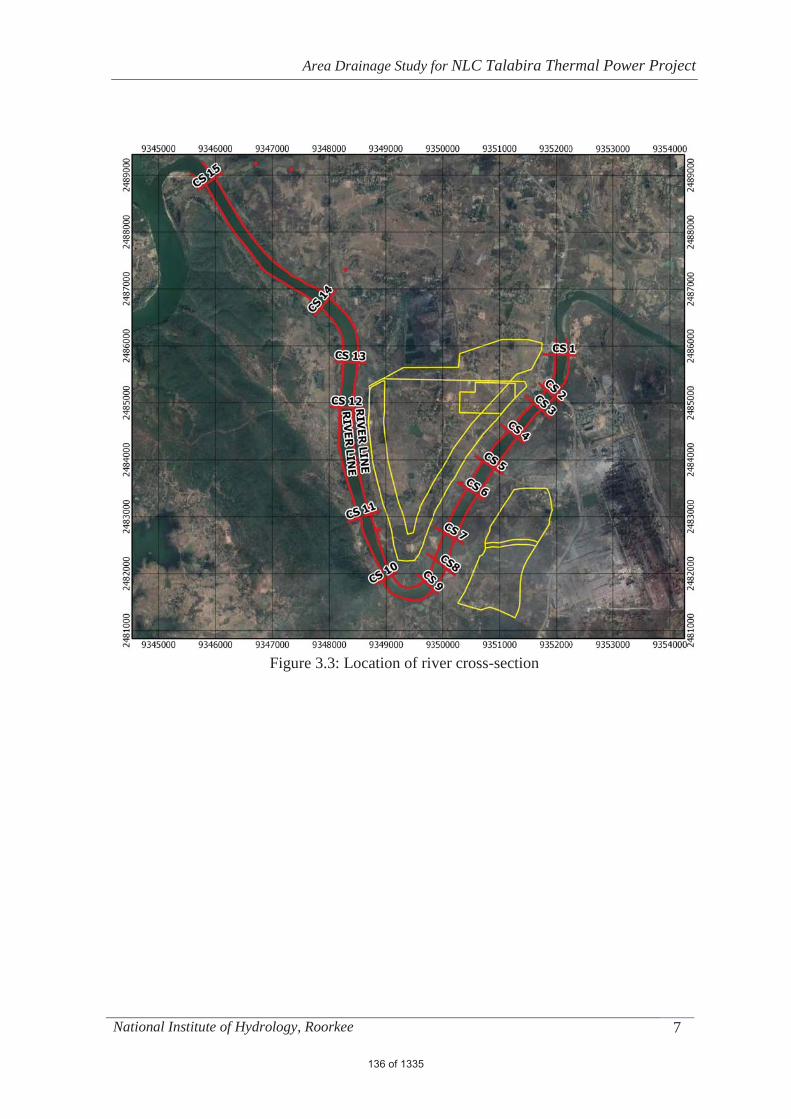
National Institute of Hydrology, Roorkee 7
Figure 3.3: Location of river cross-section
136 of 1335
Area Drainage Study for NLC Talabira Thermal Power Project
National Institute of Hydrology, Roorkee 58
Table 5.8: Maximum water level Location 50 Year 100 Year
CS2(665) 201.9 202.3
CS3(972) 201.5 201.9
CS4(1570) 201.2 201.6
CS5(2208) 201.3 201.8
CS6(2727) 201.2 201.7
CS7(3529) 200.8 201.3
CS8(4011) 200.7 201.2
CS9(4412) 200.7 201.2
CS10(5259) 200.1 200.6
CS11(6328) 200.0 200.4
CS12(8126) 199.2 199.7
CS13(8866) 199.0 199.4
CS14(9952) 198.3 198.6
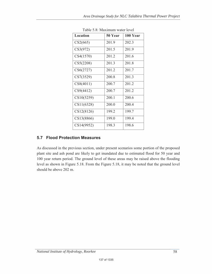
5.7 Flood Protection Measures
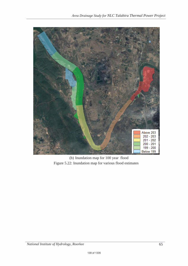
As discussed in the previous section, under present scenarios some portion of the proposed plant site and ash pond are likely to get inundated due to estimated flood for 50 year and 100 year return period. The ground level of these areas may be raised above the flooding level as shown in Figure 5.18. From the Figure 5.18, it may be noted that the ground level should be above 202 m.
137 of 1335

Area Drainage Study for NLC Talabira Thermal Power Project
National Institute of Hydrology, Roorkee 64
(a) Inundation map for 50 year flood
138 of 1335
Area Drainage Study for NLC Talabira Thermal Power Project
National Institute of Hydrology, Roorkee 65
(b) Inundation map for 100 year flood
Figure 5.22: Inundation map for various flood estimates
139 of 1335
Area Drainage Study for NLC Talabira Thermal Power Project
National Institute of Hydrology, Roorkee 66
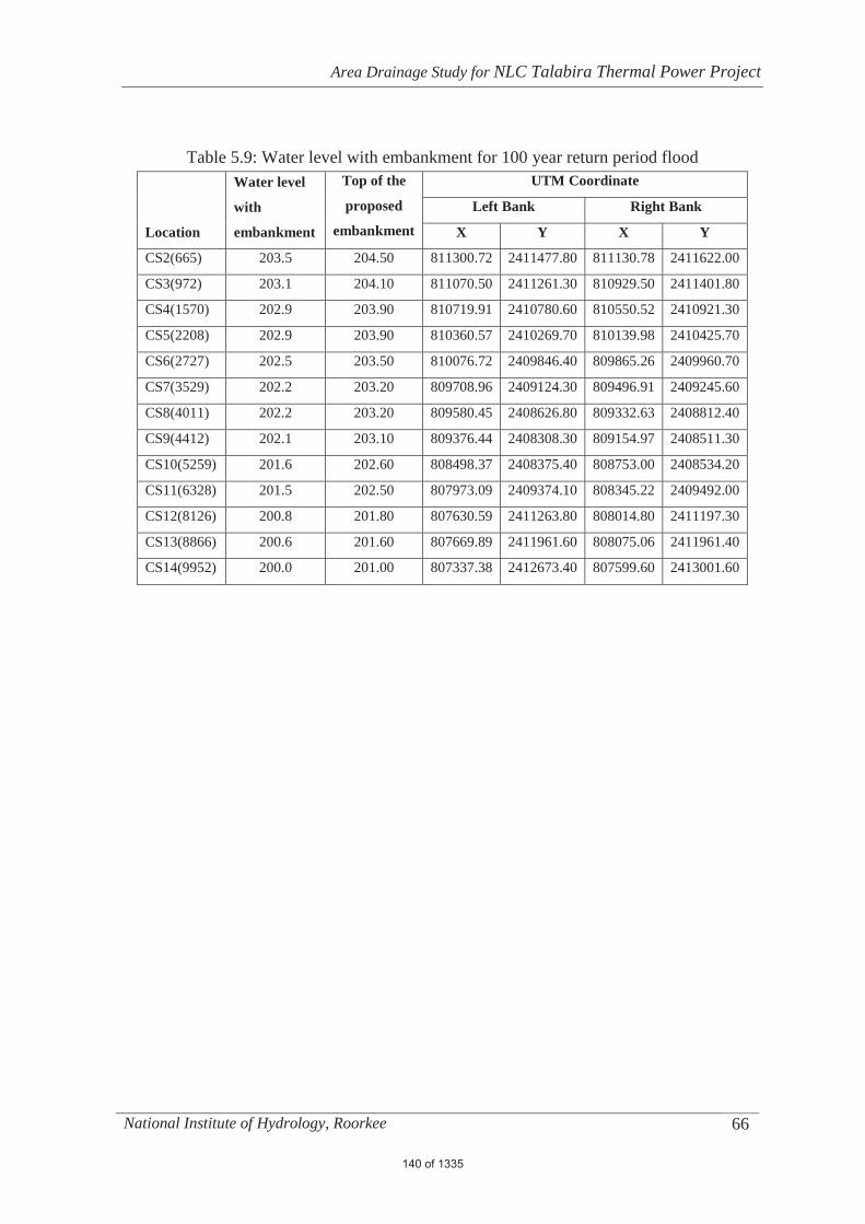
Table 5.9: Water level with embankment for 100 year return period flood
Location
Water level
with
embankment
Top of the
proposed
embankment
UTM Coordinate
Left Bank Right Bank
X Y X Y
CS2(665) 203.5 204.50 811300.72 2411477.80 811130.78 2411622.00
CS3(972) 203.1 204.10 811070.50 2411261.30 810929.50 2411401.80
CS4(1570) 202.9 203.90 810719.91 2410780.60 810550.52 2410921.30
CS5(2208) 202.9 203.90 810360.57 2410269.70 810139.98 2410425.70
CS6(2727) 202.5 203.50 810076.72 2409846.40 809865.26 2409960.70
CS7(3529) 202.2 203.20 809708.96 2409124.30 809496.91 2409245.60
CS8(4011) 202.2 203.20 809580.45 2408626.80 809332.63 2408812.40
CS9(4412) 202.1 203.10 809376.44 2408308.30 809154.97 2408511.30
CS10(5259) 201.6 202.60 808498.37 2408375.40 808753.00 2408534.20
CS11(6328) 201.5 202.50 807973.09 2409374.10 808345.22 2409492.00
CS12(8126) 200.8 201.80 807630.59 2411263.80 808014.80 2411197.30
CS13(8866) 200.6 201.60 807669.89 2411961.60 808075.06 2411961.40
CS14(9952) 200.0 201.00 807337.38 2412673.40 807599.60 2413001.60
140 of 1335

Area Drainage Study for NLC Talabira Thermal Power Project
National Institute of Hydrology, Roorkee 68
Figure 5.24: Alignment of proposed embankments over satellite images.
Left bank Right bank
Optional embankment
141 of 1335
Area Drainage Study for NLC Talabira Thermal Power Project
National Institute of Hydrology, Roorkee 69
5.8 Impact of Hirakud reservoir
The FRL/ MWL of Hirakud reservoir is at RL 192.024m (http://www.dowrorissa.gov.in/Projects/MajMed/DetailsCompletedOngoing/Ongoing/CEUMB/Hirakud%20System%20%28Completed%29/SFHirakud.pdf) and Top dam level is at R.L. 195.680 m (http://www.ohpcltd.com/Hirakud/dam). The elevations in the study area are above RL 193 m excluding river section. Moreover, the safe grade level is recommended to be above RL 202 m. This level is more than 6 m higher than top level of Hirakud dam. Hence, after construction of proposed embankments on Bhedan River and site levelling above 202 m, the water level of Hirakud reservoir will not have adverse impact on the site.
142 of 1335
National Institute of Hydrology, Roorkee 80
66 CONCLUSIONS
Based on study following conclusions are drawn:
1 The Digital Elevation Model (DEM) of the study area is prepared from surveyed contour for the plant area, spot heights; contours digitized from the SOI toposheets and SRTM data. The basin boundary and river networks are delineated from the DEM using HEC-GeoHMS and the catchment characteristics are estimated.
2 Synthetic Unit Hydrograph is developed following the guideline of Flood Estimation Report (CWC, 1993) and estimated catchment characteristics.
3 The daily rainfall data for ten raingauge stations are procured from IMD, Pune and
the annual 1-day maximum rainfall series is extracted for rainfall frequency analysis.
4 Generalized Extreme Value (GEV) is identified as the robust frequency distribution following the regional rainfall frequency analysis using the L-moments approach. The robust frequency distribution is identified based on L-moments ratio diagram and Zi dist –statistic. The 1-day annual maximum rainfall for 25 year, 50 year and 100 year return periods are estimated as 27. 25 cm, 31.04 cm and 34. 86 cm respectively.
5 The design flood hydrograph are developed by convoluting the SUH with estimated design rainfall. The peak floods in Bhedan river due 50 year and 100 year return period rainfall for 1 day are estimated to be 9956.07 m3/s and 11278.65 m3/s respectively.
6 The flood inundation study for 50 year 100 year return period flood is carried out using the coupled 1D- and 2-D hydrodynamic model Mike Flood. The 1-D model in Mike 11 is prepared for the study reach of Bhedan river using surveyed river cross-section at fifteen locations. The 2D model in Mike 21 is developed for both main plant area and ash pond area using 10m cell size.
7 Under pre-project condition the maximum water level in the river varies from 201.5 m to 199 m along the river stretch from CS3 to CS 13 for 50 year return
143 of 1335

Area Drainage Study for NLC Talabira Thermal Power Project
National Institute of Hydrology, Roorkee 81
period flood. The flood levels are about 0.4 m higher in case of 100 year return period flood.
8 The potential source of flooding at the plant site can be due to the flooding from Bhedan rive in the areas below RL202 m level. Hence, the safe grade level is recommended to be above RL 202 m.
9 Further, construction of embankments on both left and right bank is also analysed
for various return period floods. It is suggested that embankment is to be constructed on both banks, as construction of embankments only in right bank (main plant area) will not be able to protect the ash pond area. However, instead of creating embankment along the left bank of river, selective protection to only ash dyke can be made.
10 The water level in river with embankment varies from 203.1 m to 200.6 m along
the river reach form CS3 to CS 13 for 100 year return period flood. It is also observed that present embankment of different stretches along the right bank are not flooded in the modelling study. However, presently the embankment is not continuous.
11 It is observed that the main plant area has negligible flow from the upstream area and can be easily diverted along the plan boundary/ periphery road. However, two natural stream/nall are observed in and around the ash pond area flowing from east (from Bhushan plant) to west and joins Bhedan river.
12 The drain in the north of proposed ash pond area of NLCIL will not interfere with the ash pond area of NLCIL. The other drain (D2) passes through the proposed ash pond area of NLCIL and joins to Bhedan river. Two alternatives for the drain D2 are analysed.
13 The first alternative is to leave the alignment of drain D2 as it is, dividing the ash pond area in two portions and area north of drain may be used for fly ash pond and area south of drain may be used for bottom ash pond. In this case there will be very little modification in the present alignment of the drain as the drain may be straightened and strengthened with capacity in the area between the fly ash pond and bottom ash pond. However, the drain caries discharge from Bhushan plant area including discharge from iron ore washing plant etc. Hence it will be difficult for controlling water quality in the drain section where it passes through the ash pond area.
144 of 1335
Area Drainage Study for NLC Talabira Thermal Power Project
National Institute of Hydrology, Roorkee 82
14 As second alternative, it is proposed to divert the drain along the boundary of ash pond area in by diverting to first south and then west direction. However, it is to be noted that in two stretches the cutting would be in the range of about 8 m to maintain bed slope of drain.
15 The estimated peak runoff in the drain for 50 year and 100 year return period are 55.5 m3/s and 61.3 m3/s. The Trapezoidal section drains are designed with a side slope of 1.5:1 (H:V) and longitudinal slope of 0.0015 m/m (1.5 m/km) to carry the runoff generated locally.
145 of 1335

National Institute of Hydrology, Roorkee 86
AAnnexure-I Annual 1 day maximum rainfall (mm) at various stations
Year Deog
arh Jaman
kiru Jharsug
uda Kirim
ira Kolob
ira Kuchi
nda Kusu
mi Kutr
a Laikera_
BL_II Sambal
pur 1960 161.6 295.8 290.7 1961 197.9 254.2 220.4 1962 85.4 72.5 131 1963 155.4 164.6 156.4 1964 109.6 184.2 308.6 1965 67.6 211.4 98.3 1966 113.8 135.5 136.7 1967 237 132 116 156 188.5 1968 197.9 132.6 156 1969 186.6 101.1 113.2 1970 102 129 1971 180 110.6 198.3 200.6 100 156.2 1972 137.8 85.2 131.3 1973 259 190.9 299.4 308.4 185 174.2 1974 114 102.3 170.2 94.1 101.4 1975 203.2 257.8 413 102.2 1976 128 131.4 180 205 1977 75 116.4 69 87.2 1978 115 103 265 42.4 1979 126 81.4 70 63.4 1980 120.3 160 188.1 1981 100 82.2 57 42 188 57.5 94 1982 112 196 83.1 581.9 1983 147 110.2 164.2 91 206.8 1984 219 128 278.6 182 177 1985 205 97.7 130.6 132 216.8 1986 178.8 118.3 143.2 91 167.8 1987 55 127.1 209.2 187 100.8 1988 87 92.3 148.2 68 95.6 1989 113 174.3 155.6 86 86.4 1990 132.6 83.2 84.8 112 107.8 1991 176 118.7 126 133 120 129.6 105 94 193.1 1992 210 153 96 139 158 68 78 159.6 1993 80.2 130.8 233.8 200.8 1994 74.8 123 185.6 178 104 121.4 227.4 119 115 189.2 1995 101 152.7 86 78 60 217 74 62 95.6 1996 177 96.6 108 147 218.5 220.8 123 146 126 1997 84 53 123.4 52 68 41.4 110.4 91 40 199
146 of 1335
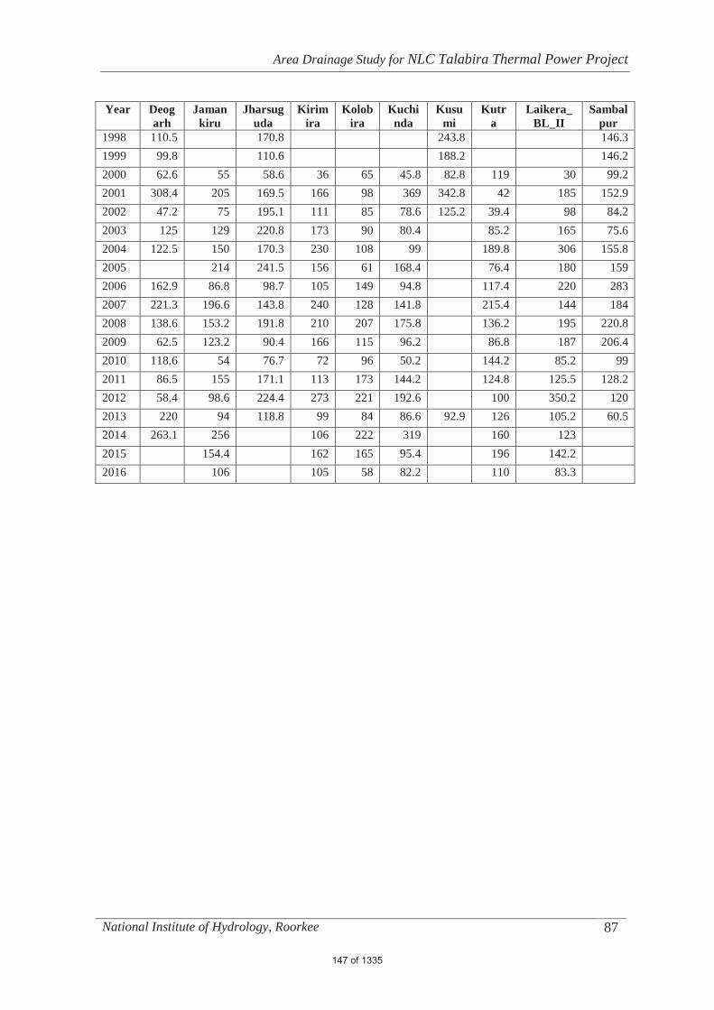
Area Drainage Study for NLC Talabira Thermal Power Project
National Institute of Hydrology, Roorkee 87
Year Deogarh
Jamankiru
Jharsuguda
Kirimira
Kolobira
Kuchinda
Kusumi
Kutra
Laikera_BL_II
Sambalpur
1998 110.5 170.8 243.8 146.3 1999 99.8 110.6 188.2 146.2 2000 62.6 55 58.6 36 65 45.8 82.8 119 30 99.2 2001 308.4 205 169.5 166 98 369 342.8 42 185 152.9 2002 47.2 75 195.1 111 85 78.6 125.2 39.4 98 84.2 2003 125 129 220.8 173 90 80.4 85.2 165 75.6 2004 122.5 150 170.3 230 108 99 189.8 306 155.8 2005 214 241.5 156 61 168.4 76.4 180 159 2006 162.9 86.8 98.7 105 149 94.8 117.4 220 283 2007 221.3 196.6 143.8 240 128 141.8 215.4 144 184 2008 138.6 153.2 191.8 210 207 175.8 136.2 195 220.8 2009 62.5 123.2 90.4 166 115 96.2 86.8 187 206.4 2010 118.6 54 76.7 72 96 50.2 144.2 85.2 99 2011 86.5 155 171.1 113 173 144.2 124.8 125.5 128.2 2012 58.4 98.6 224.4 273 221 192.6 100 350.2 120 2013 220 94 118.8 99 84 86.6 92.9 126 105.2 60.5 2014 263.1 256 106 222 319 160 123 2015 154.4 162 165 95.4 196 142.2 2016 106 105 58 82.2 110 83.3
147 of 1335

Area Drainage Study for NLC Talabira Thermal Power Project
National Institute of Hydrology, Roorkee 88
AAnnexure-II Effective rainfall and Runoff for various return period
Time
(h) 50 Year 100 Year
Rainfall (cm) Runoff (m3/s) Rainfall (cm) Runoff (m3/s) 1 0.407 318.55 0.476 318.55 2 0.407 322.01 0.476 322.6 3 0.407 328.93 0.476 330.69 4 0.407 338.29 0.476 341.64 5 0.546 350.5 0.632 355.92 6 0.546 367.55 0.632 375.81 7 0.546 391.49 0.632 403.69 8 0.685 421.95 0.788 439.17 9 0.546 464.75 0.632 488.96 10 0.407 521.01 0.476 554.45 11 0.407 592.33 0.476 637.53 12 0.268 682.88 0.319 743.05 13 0.685 795.51 0.788 874.31 14 0.685 937.59 0.788 1039.73 15 0.964 1110.56 1.101 1240.96 16 0.964 1318.91 1.101 1483.1 17 1.521 1563.45 1.727 1767.11 18 1.799 1832.73 2.039 2079.42 19 2.634 2116.05 2.978 2407.29 20 4.583 2410.51 5.167 2747.15 21 2.077 2732.64 2.352 3117.37 22 1.242 3055.67 1.414 3487.88 23 0.825 3371.46 0.945 3849.63 24 0.685 3690.58 0.788 4214.54 25 4020.99 4591.56 26 4374.84 4994.31 27 4762 5433.81 28 5221.53 5954.04 29 5754.9 6556.7 30 6356.57 7235.56 31 7009.76 7971.63 32 7686.18 8733.2 33 8359.81 9490.88 34 8983.29 10191.4 35 9510.77 10783.21 36 9877.73 11193.63 37 9956.07 11278.65 38 9744.14 11036.34
148 of 1335
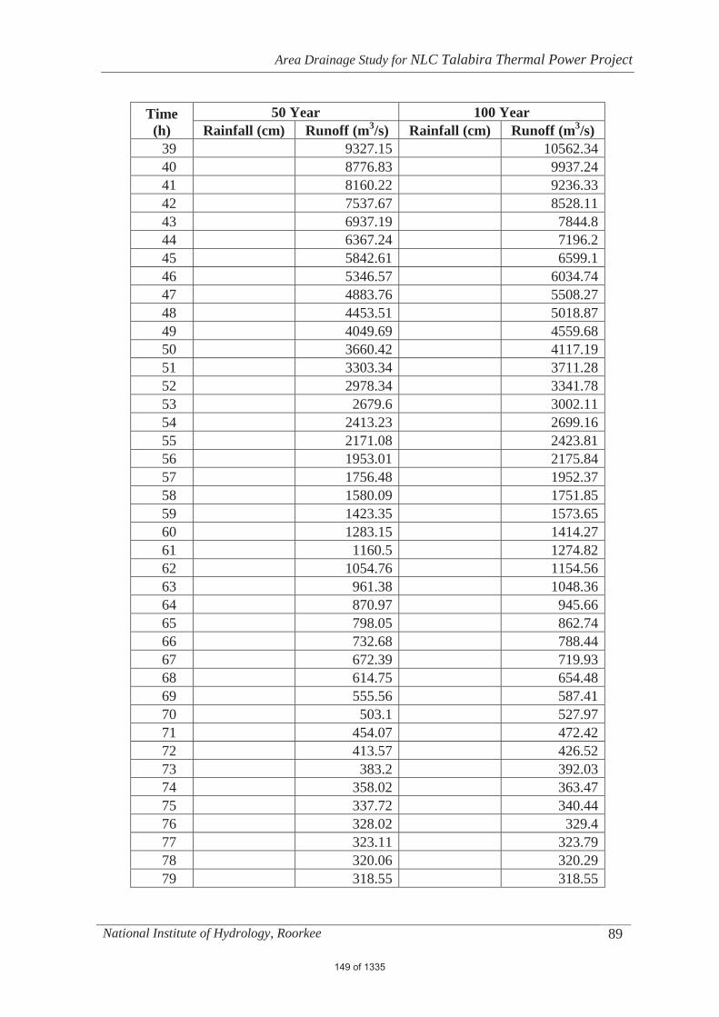
Area Drainage Study for NLC Talabira Thermal Power Project
National Institute of Hydrology, Roorkee 89
Time (h)
50 Year 100 Year Rainfall (cm) Runoff (m3/s) Rainfall (cm) Runoff (m3/s)
39 9327.15 10562.34 40 8776.83 9937.24 41 8160.22 9236.33 42 7537.67 8528.11 43 6937.19 7844.8 44 6367.24 7196.2 45 5842.61 6599.1 46 5346.57 6034.74 47 4883.76 5508.27 48 4453.51 5018.87 49 4049.69 4559.68 50 3660.42 4117.19 51 3303.34 3711.28 52 2978.34 3341.78 53 2679.6 3002.11 54 2413.23 2699.16 55 2171.08 2423.81 56 1953.01 2175.84 57 1756.48 1952.37 58 1580.09 1751.85 59 1423.35 1573.65 60 1283.15 1414.27 61 1160.5 1274.82 62 1054.76 1154.56 63 961.38 1048.36 64 870.97 945.66 65 798.05 862.74 66 732.68 788.44 67 672.39 719.93 68 614.75 654.48 69 555.56 587.41 70 503.1 527.97 71 454.07 472.42 72 413.57 426.52 73 383.2 392.03 74 358.02 363.47 75 337.72 340.44 76 328.02 329.4 77 323.11 323.79 78 320.06 320.29 79 318.55 318.55
149 of 1335

Area Drainage Study for NLC Talabira Thermal Power Project
National Institute of Hydrology, Roorkee 90
AAnnexure-III Cross Section profile with embankment
150 of 1335

Area Drainage Study for NLC Talabira Thermal Power Project
National Institute of Hydrology, Roorkee 91
151 of 1335
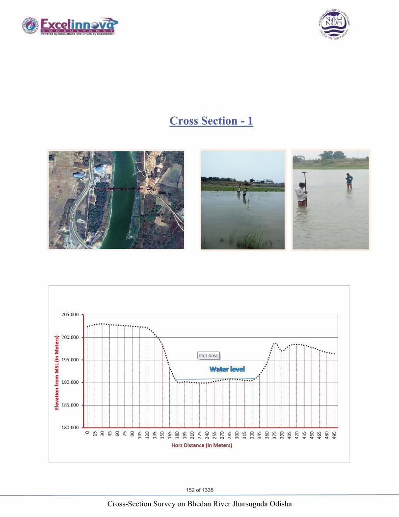
Cross-Section Survey on Bhedan River Jharsuguda Odisha
Cross Section - 1
152 of 1335
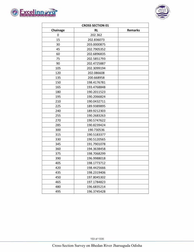
Cross-Section Survey on Bhedan River Jharsuguda Odisha
CROSS SECTION 01 Chainage RL Remarks
0 202.362 15 202.836073 30 203.0000875 45 202.7905352 60 202.6896835 75 202.5851793 90 202.4725887
105 202.3099194 120 202.086608 135 200.668958 150 198.4176781 165 193.4768848 180 190.2011523 195 190.2066824 210 190.0432711 225 189.9389895 240 189.9212303 255 190.2683263 270 190.5747622 285 190.8239424 300 190.730536 315 190.5183377 330 190.5120565 345 191.7901078 360 194.3638458 375 198.7068299 390 196.9988018405 198.1773712 420 198.4425666 435 198.2319406 450 197.8045302 465 197.1784823 480 196.6835214 495 196.3745428
153 of 1335
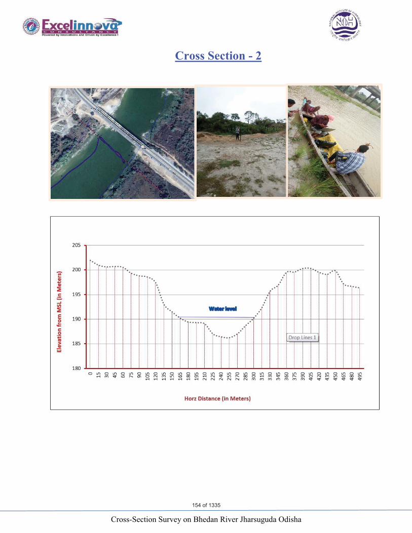
Cross-Section Survey on Bhedan River Jharsuguda Odisha
Cross Section - 2
154 of 1335
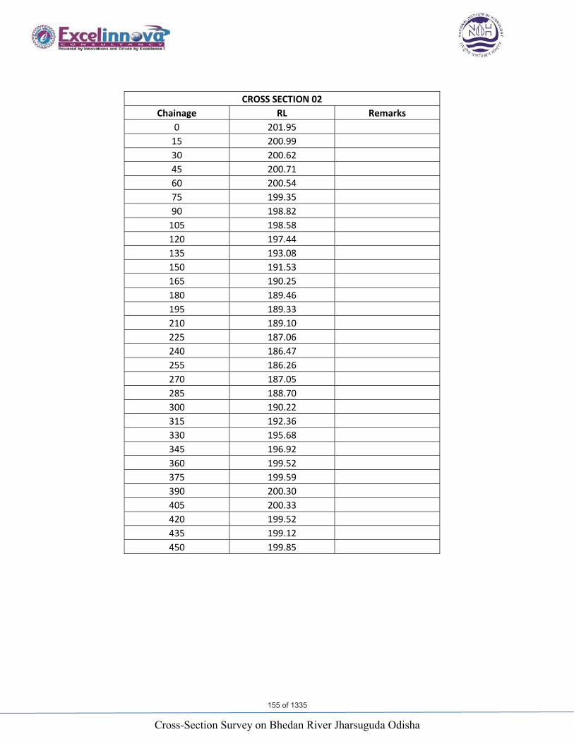
Cross-Section Survey on Bhedan River Jharsuguda Odisha
CROSS SECTION 02 Chainage RL Remarks
0 201.95 15 200.99 30 200.62 45 200.71 60 200.54 75 199.35 90 198.82
105 198.58 120 197.44 135 193.08 150 191.53165 190.25 180 189.46 195 189.33 210 189.10 225 187.06 240 186.47 255 186.26 270 187.05 285 188.70 300 190.22 315 192.36 330 195.68 345 196.92 360 199.52 375 199.59 390 200.30 405 200.33 420 199.52 435 199.12 450 199.85
155 of 1335
Cross-Section Survey on Bhedan River Jharsuguda Odisha
Cross Section – 3
156 of 1335
Cross-Section Survey on Bhedan River Jharsuguda Odisha
CROSS SECTION 03 Chainage RL Remarks
0 199.17 15 201.52 30 201.69 45 201.49 60 201.33 75 201.26 90 201.16
105 201.33 120 199.72 135 196.64 150 194.03 165 195.61 180 192.19 195 192.28 210 191.45 225 189.90 240 189.76 255 190.09 270 190.22 285 189.49 300 188.81 315 188.03 330 189.82 345 190.96 360 195.12 375 196.82 390 197.78405 197.22 420 198.11 435 199.56 450 201.00 465 201.55 480 201.55 495 201.57 510 201.48 525 201.43 535 201.40
157 of 1335

Cross-Section Survey on Bhedan River Jharsuguda Odisha
Cross Section - 4
158 of 1335
Cross-Section Survey on Bhedan River Jharsuguda Odisha
CROSS SECTION 04 Chainage RL Remark
0 198.07 15 197.89 30 197.93 45 198.25 60 198.98 75 199.46 90 199.72
105 199.60 120 198.63 135 198.60 150 194.78165 190.34 180 189.87 195 189.99 210 190.17 225 190.12 240 190.16 255 190.28 270 190.21 285 191.28 300 191.08 315 190.89 330 192.61 345 195.30 360 197.45 375 197.35 390 197.70 405 197.22 420 197.03 435 196.89 450 197.01 465 197.23 476 197.74
159 of 1335
Cross-Section Survey on Bhedan River Jharsuguda Odisha
Cross Section – 5
160 of 1335

Cross-Section Survey on Bhedan River Jharsuguda Odisha
CROSS SECTION 05 Chainage RL Remark
0 199.986 15 198.927 30 197.772 45 196.26 60 195.844 75 195.747 90 195.904
105 196.782 120 196.77 135 193.54 150 191.337 165 190.804 180 190.756 195 190.77 210 190.605 225 190.588 240 190.211 255 189.532 270 188.851 285 189.511 300 190.019 315 190.17 330 191.152 345 191.892 360 193.427 375 196.179 390 197.508405 198.369 420 196.437 435 195.433 450 196.127 465 198.268 480 198.205 495 198.205 499 198.178
161 of 1335

Cross-Section Survey on Bhedan River Jharsuguda Odisha
Cross Section - 6
162 of 1335

Cross-Section Survey on Bhedan River Jharsuguda Odisha
CROSS SECTION 06 Chainage RL Remark
0 200.126 15 200.386 30 201.135 45 201.917 60 200.676 75 199.761 90 197.969
105 198.284 120 197.622 135 196.079 150 197.103 165 194.505 180 190.547 195 190.787 210 190.977 225 190.762 240 189.439 255 189.099 270 189.454 285 188.918 300 188.857 315 189.82330 190.088 345 190.433 360 192.082 375 194.059 390 195.86 405 197.124 420 197.262 435 198.226 450 195.559 465 195.532 480 195.074 495 194.958 498 194.955
163 of 1335
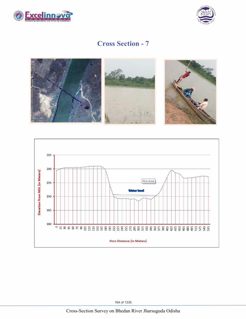
Cross-Section Survey on Bhedan River Jharsuguda Odisha
Cross Section - 7
164 of 1335

Cross-Section Survey on Bhedan River Jharsuguda Odisha
CROSS SECTION 07 Chainage RL Remark
0 199.43 15 200.048 30 200.432 45 200.459 60 200.448 75 200.497 90 200.527
105 200.696 120 200.91 135 200.981 150 200.998 165 200.795 180 199.321 195 194.258 210 190.03 225 189.32 240 189.25 255 189.263 270 189.043 285 189.129 300 188.379 315 189.38 330 189.392 345 189.034 360 190.008 375 191.256 390 193.899405 197.02 420 199.474 435 198.591 450 198.172 465 196.701 480 196.711 495 196.806 510 197.033 525 197.26 540 197.381 555 197.161
165 of 1335
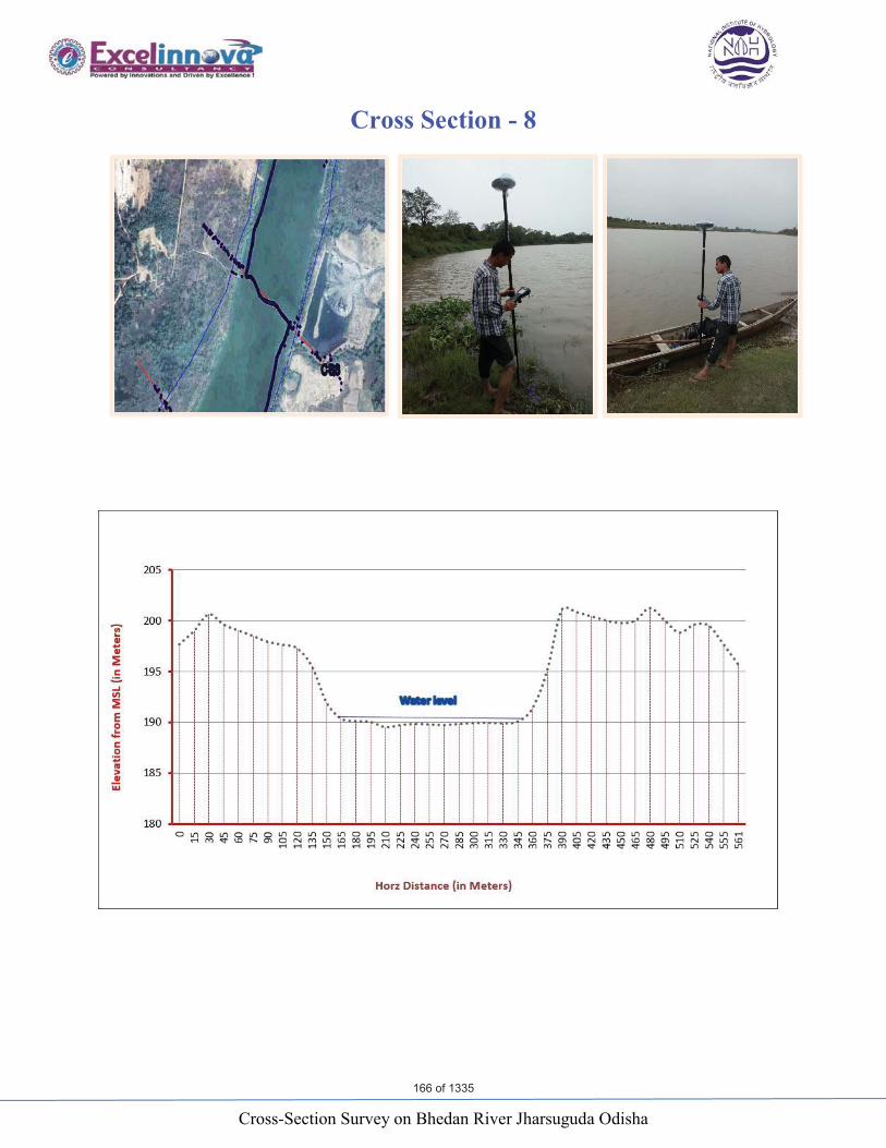
Cross-Section Survey on Bhedan River Jharsuguda Odisha
Cross Section - 8
166 of 1335
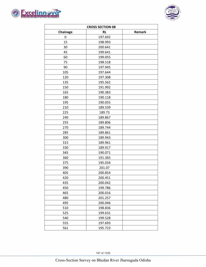
Cross-Section Survey on Bhedan River Jharsuguda Odisha
CROSS SECTION 08 Chainage RL Remark
0 197.692 15 198.993 30 200.641 45 199.641 60 199.055 75 198.518 90 197.945
105 197.644 120 197.308 135 195.562 150 191.992 165 190.383 180 190.118 195 190.055 210 189.539 225 189.73 240 189.867 255 189.806 270 189.744 285 189.861 300 189.943 315 189.961 330 189.917 345 190.071 360 191.365 375 195.034 390 201.07405 200.854 420 200.451 435 200.042 450 199.786 465 200.016 480 201.257 495 200.046 510 198.836 525 199.631 540 199.528 555 197.693 561 195.723
167 of 1335

Cross-Section Survey on Bhedan River Jharsuguda Odisha
Cross Section - 9
168 of 1335

Cross-Section Survey on Bhedan River Jharsuguda Odisha
CROSS SECTION 09 Chainage RL Remark
0 197.173 15 198.03 30 198.441 45 198.145 60 197.09 75 197.314 90 195.188
105 194.123 120 193.309 135 192.425 150 190.591 165 190.425 180 189.842 195 189.559 210 189.578 225 189.57 240 189.518 255 189.599 270 189.546 285 189.531 300 189.51 315 189.356 330 189.662 345 190.411 360 195.263 375 197.412 390 198.294405 197.878 420 197.278 435 196.686 442 196.881
169 of 1335
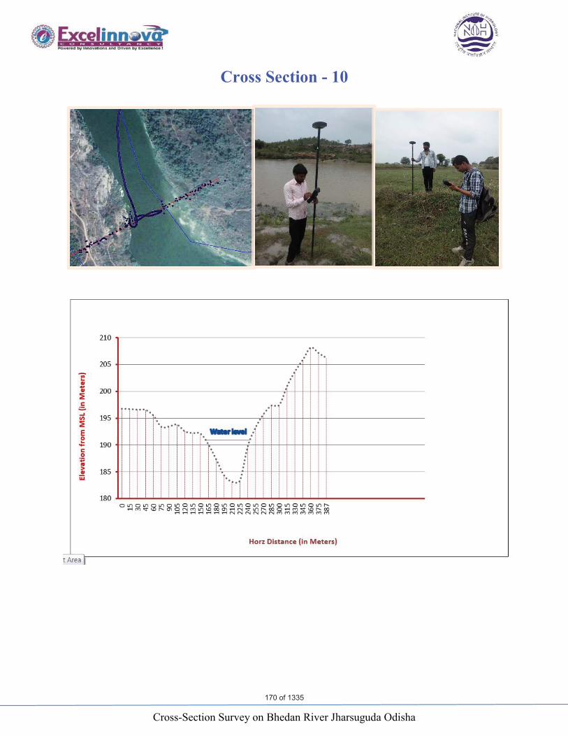
Cross-Section Survey on Bhedan River Jharsuguda Odisha
Cross Section - 10
170 of 1335
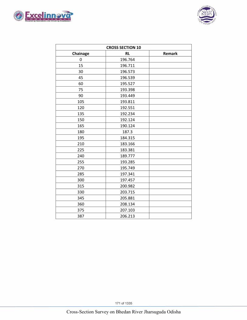
Cross-Section Survey on Bhedan River Jharsuguda Odisha
CROSS SECTION 10 Chainage RL Remark
0 196.764 15 196.711 30 196.573 45 196.539 60 195.527 75 193.398 90 193.449
105 193.811 120 192.551 135 192.234 150 192.124 165 190.124180 187.3 195 184.315 210 183.166 225 183.381 240 189.777 255 193.285 270 195.749 285 197.341 300 197.457 315 200.982 330 203.715 345 205.881 360 208.134 375 207.103 387 206.213
171 of 1335

Cross-Section Survey on Bhedan River Jharsuguda Odisha
Cross Section - 11
172 of 1335
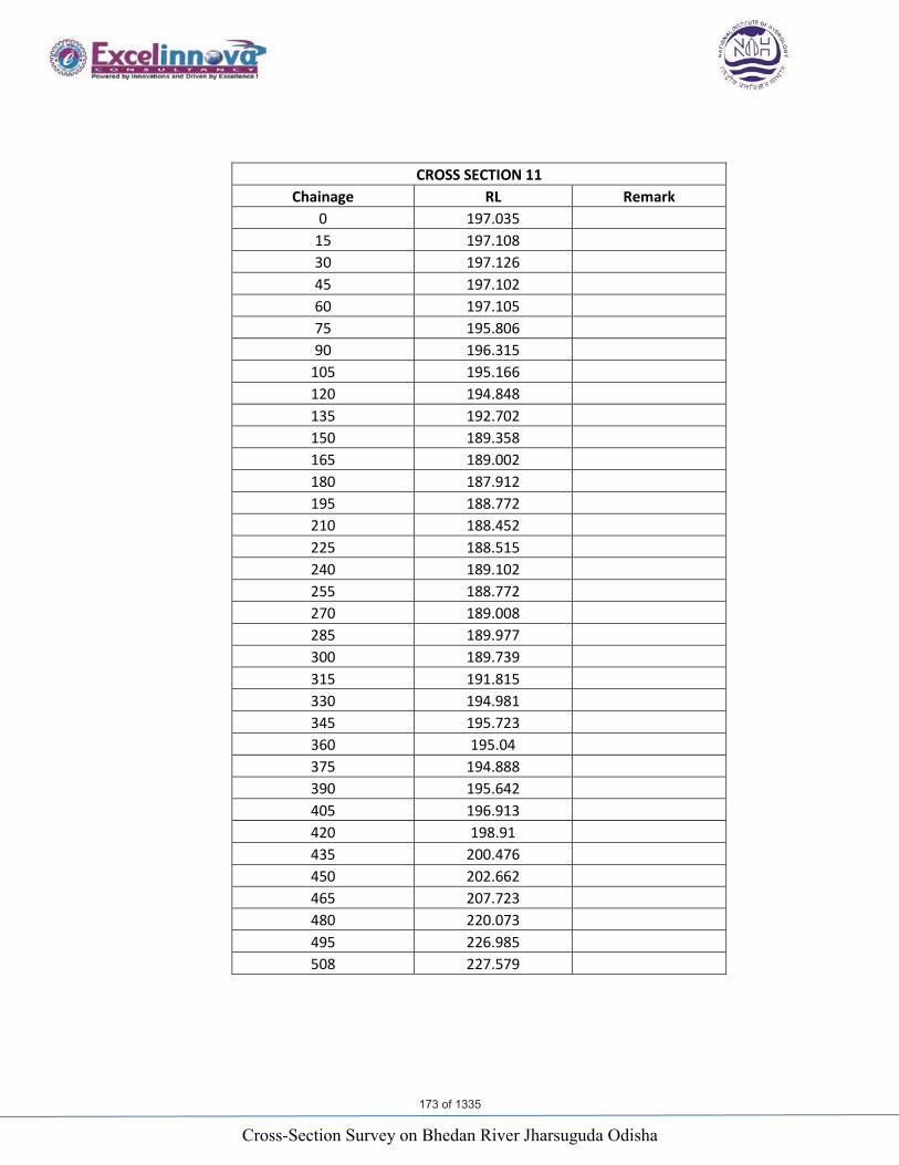
Cross-Section Survey on Bhedan River Jharsuguda Odisha
CROSS SECTION 11 Chainage RL Remark
0 197.035 15 197.108 30 197.126 45 197.102 60 197.105 75 195.806 90 196.315
105 195.166 120 194.848 135 192.702 150 189.358 165 189.002 180 187.912 195 188.772 210 188.452 225 188.515 240 189.102 255 188.772 270 189.008 285 189.977 300 189.739 315 191.815 330 194.981 345 195.723360 195.04 375 194.888 390 195.642 405 196.913 420 198.91 435 200.476 450 202.662 465 207.723 480 220.073 495 226.985 508 227.579
173 of 1335

Cross-Section Survey on Bhedan River Jharsuguda Odisha
Cross Section - 12
174 of 1335

Cross-Section Survey on Bhedan River Jharsuguda Odisha
CROSS SECTION 12 Chainage RL Remark
0 193.982 15 193.964 30 194.323 45 194.975 60 195.329 75 196.636 90 197.731
105 197.823 120 197.82 135 198.146 150 197.664 165 193.215 180 190.425 195 190.293 210 190.107 225 190.003 240 189.791 255 189.909 270 189.722 285 189.352 300 189.412 315 189.408 330 189.672 345 189.852 360 189.838 375 189.762 390 194.786405 195.082 420 194.411 435 193.919 450 193.954 465 194.48 480 195.564 495 196.703 510 198.015 525 198.763 528 198.86
175 of 1335

Cross-Section Survey on Bhedan River Jharsuguda Odisha
Cross Section - 13
176 of 1335
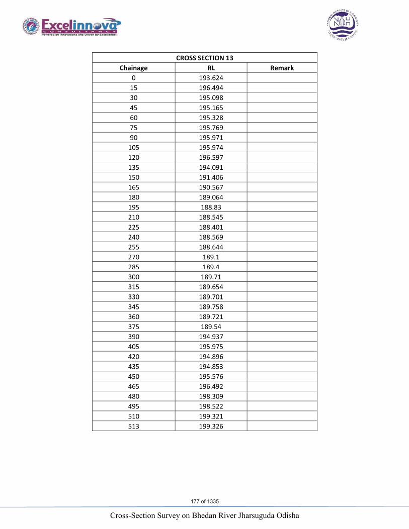
Cross-Section Survey on Bhedan River Jharsuguda Odisha
CROSS SECTION 13 Chainage RL Remark
0 193.624 15 196.494 30 195.09845 195.16560 195.328 75 195.769 90 195.971
105 195.974 120 196.597 135 194.091 150 191.406 165 190.567 180 189.064 195 188.83 210 188.545 225 188.401 240 188.569 255 188.644 270 189.1 285 189.4 300 189.71 315 189.654 330 189.701 345 189.758 360 189.721 375 189.54 390 194.937 405 195.975 420 194.896 435 194.853 450 195.576 465 196.492 480 198.309495 198.522 510 199.321 513 199.326
177 of 1335

Cross-Section Survey on Bhedan River Jharsuguda Odisha
Cross Section - 14
178 of 1335
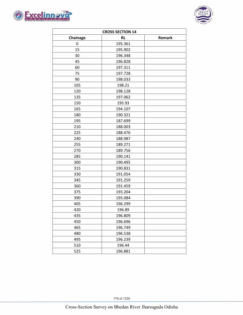
Cross-Section Survey on Bhedan River Jharsuguda Odisha
CROSS SECTION 14 Chainage RL Remark
0 195.361 15 195.902 30 196.348 45 196.828 60 197.311 75 197.728 90 198.033
105 198.21 120 198.128 135 197.062 150 195.93 165 194.107 180 190.321 195 187.699 210 188.003 225 188.476 240 188.987 255 189.271 270 189.756 285 190.141 300 190.495 315 190.831 330 191.054 345 191.259 360 191.459 375 193.204 390 195.084405 196.299 420 196.89 435 196.809 450 196.696 465 196.749 480 196.538 495 196.239 510 196.44 525 196.881
179 of 1335

Cross-Section Survey on Bhedan River Jharsuguda Odisha
Cross Section - 15
180 of 1335
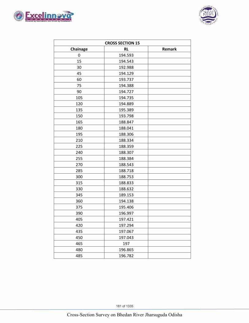
Cross-Section Survey on Bhedan River Jharsuguda Odisha
CROSS SECTION 15 Chainage RL Remark
0 194.593 15 194.543 30 192.988 45 194.129 60 193.737 75 194.388 90 194.727
105 194.735 120 194.889 135 195.389 150 193.798165 188.847 180 188.041 195 188.306 210 188.334 225 188.359 240 188.307 255 188.384 270 188.543 285 188.718 300 188.753 315 188.833 330 188.632 345 189.153 360 194.138 375 195.406 390 196.997 405 197.421 420 197.294 435 197.067 450 197.043 465 197 480 196.865 485 196.782
181 of 1335

Area Drainage Study for 3×800 MW OTPP
National Institute of Hydrology, Roorkee 80
NATIONAL INSTITUTE OF HYDROLOGYROORKEE – 247 667, UTTARAKHANDWebsite: http://www.nihroorkee.gov.in
0.10 0.30 0.500.00 0.20 0.40L-Skewness
-0.10
0.10
0.30
-0.20
0.00
0.20
0.40L-
Kurto
sis
GLO
GEV GNO
GPA
PE3
WAKEXPEV1
LOS
NOR
UNF
(GLO, GEV, GNO, GPA, PE3 are three-parameter distributions, and are shown as lines.
WAK is a five-parameter distribution, and is shown as a line.
UNF, NOR, LOS, EV1 and EXP are two-parameterdistributions shown as points, and are mentioned in italics)
Regional Average
182 of 1335