annexure -2 to corrigendum -1 dated 24.09.2011 …gailtenders.in/writereaddata/corrigendum/annexure...
TRANSCRIPT
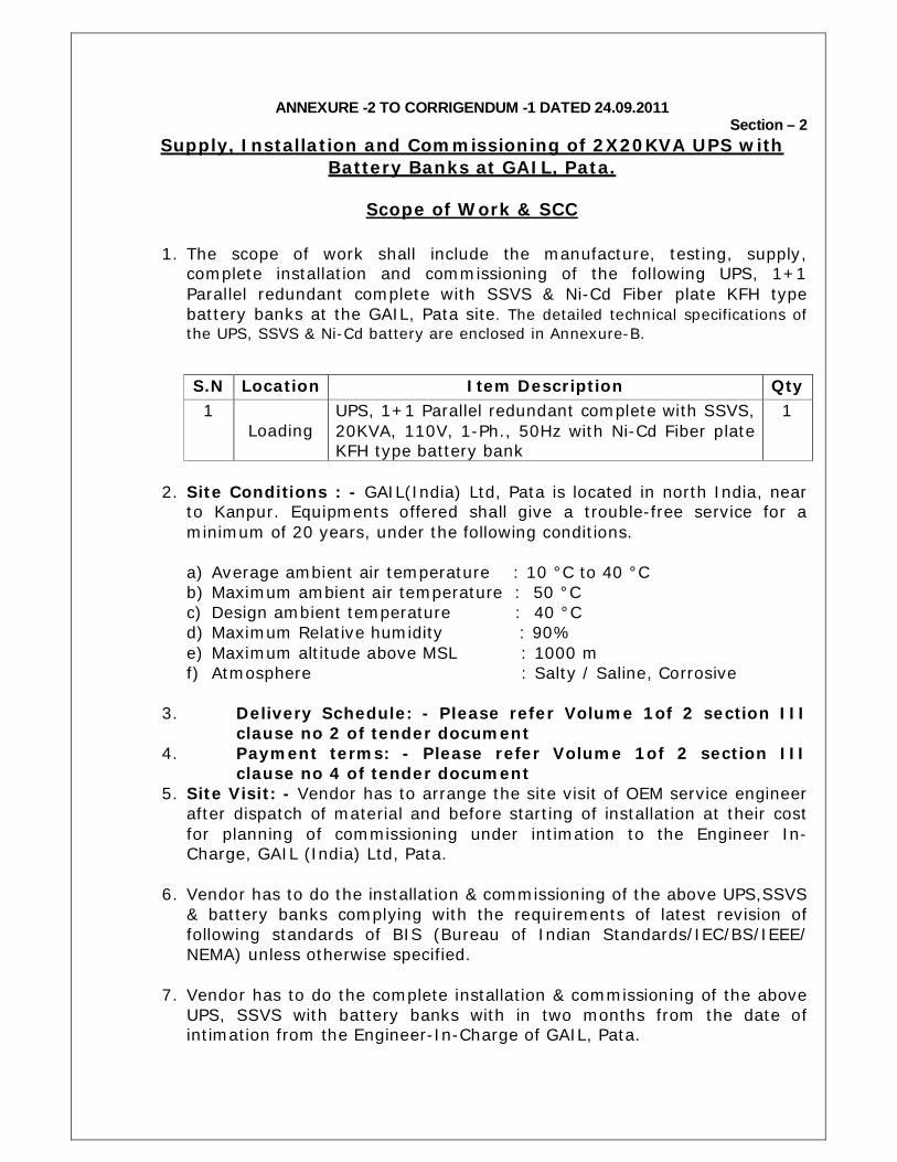
ANNEXURE -2 TO CORRIGENDUM -1 DATED 24.09.2011 Section – 2
Supply, Installation and Commissioning of 2X20KVA UPS with Battery Banks at GAIL, Pata.
Scope of Work & SCC
1. The scope of work shall include the manufacture, testing, supply,
complete installation and commissioning of the following UPS, 1+1 Parallel redundant complete with SSVS & Ni-Cd Fiber plate KFH type battery banks at the GAIL, Pata site. The detailed technical specifications of the UPS, SSVS & Ni-Cd battery are enclosed in Annexure-B.
2. Site Conditions : - GAIL(India) Ltd, Pata is located in north India, near
to Kanpur. Equipments offered shall give a trouble-free service for a minimum of 20 years, under the following conditions.
a) Average ambient air temperature : 10 °C to 40 °C b) Maximum ambient air temperature : 50 °C c) Design ambient temperature : 40 °C d) Maximum Relative humidity : 90% e) Maximum altitude above MSL : 1000 m f) Atmosphere : Salty / Saline, Corrosive
3. Delivery Schedule: - Please refer Volume 1of 2 section III
clause no 2 of tender document 4. Payment terms: - Please refer Volume 1of 2 section III
clause no 4 of tender document 5. Site Visit: - Vendor has to arrange the site visit of OEM service engineer
after dispatch of material and before starting of installation at their cost for planning of commissioning under intimation to the Engineer In-Charge, GAIL (India) Ltd, Pata.
6. Vendor has to do the installation & commissioning of the above UPS,SSVS
& battery banks complying with the requirements of latest revision of following standards of BIS (Bureau of Indian Standards/IEC/BS/IEEE/ NEMA) unless otherwise specified.
7. Vendor has to do the complete installation & commissioning of the above
UPS, SSVS with battery banks with in two months from the date of intimation from the Engineer-In-Charge of GAIL, Pata.
S.N Location Item Description Qty 1
Loading UPS, 1+1 Parallel redundant complete with SSVS, 20KVA, 110V, 1-Ph., 50Hz with Ni-Cd Fiber plate KFH type battery bank
1
8. Vendor has to depute service engineer for installation & commissioning of above UPS with Ni-Cd battery banks with in seven days of intimation from the Engineer-In-Charge of GAIL, Pata.
9. Dismantling of existing old UPS, SSVS with lead-acid battery banks and
complete installation, testing & commissioning of the above new UPS, SSVS with Ni-Cd battery banks shall be under the scope of vendor. Labour shall be provided by the GAIL.
10. Vendor shall provide all required tools & tackles for installation and
commissioning of above UPS, SSVS & Ni-Cd battery banks. 11. All the testing & commissioning data of the above UPS, SSVS with
battery banks shall be recorded by the vendor and submitted to the EIC of GAIL, Pata after the commissioning.
12. Vendor shall give operation & maintenance manuals to the Engineer-In-
charge of GAIL, Pata.
13. Vendor has to study & suggest all safety aspects for this & carry out all safety installations.
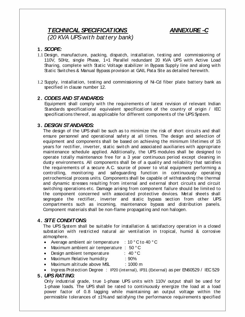
TECHNICAL SPECIFICATIONS ANNEXURE –C (20 KVA UPS with battery bank)
1. SCOPE: 1.1 Design, manufacture, packing, dispatch, installation, testing and commissioning of
110V, 50Hz, single Phase, 1+1 Parallel redundant 20 KVA UPS with Active Load Sharing, complete with Static Voltage stabilizer in Bypass Supply line and along with Static Switches & Manual Bypass provision at GAIL Pata Site as detailed herewith.
1.2 Supply, installation, testing and commissioning of Ni-Cd fiber plate battery bank as
specified in clause number 12. 2. CODES AND STANDARDS:
Equipment shall comply with the requirements of latest revision of relevant Indian Standards specifications/ equivalent specifications of the country of origin / IEC specifications thereof, as applicable for different components of the UPS System.
3. DESIGN STANDARDS:
The design of the UPS shall be such as to minimize the risk of short circuits and shall ensure personnel and operational safety at all times. The design and selection of equipment and components shall be based on achieving the minimum lifetimes of 15 years for rectifier, inverter, static switch and associated auxiliaries with appropriate maintenance schedule applied. Additionally, the UPS modules shall be designed to operate totally maintenance free for a 3 year continuous period except cleaning in dusty environments. All components shall be of a quality and reliability that satisfies the requirements of a secure A.C. source of power to vital equipment performing a controlling, monitoring and safeguarding function in continuously operating petrochemical process units. Components shall be capable of withstanding the thermal and dynamic stresses resulting from internal and external short circuits and circuit switching operations etc. Damage arising from component failure should be limited to the component concerned with associated protective devices. Metal sheets shall segregate the rectifier, inverter and static bypass section from other UPS compartments such as incoming, maintenance bypass and distribution panels. Component materials shall be non-flame propagating and non halogen.
4. SITE CONDITONS:
The UPS System shall be suitable for installation & satisfactory operation in a closed substation with restricted natural air ventilation in tropical, humid & corrosive atmosphere. Average ambient air temperature : 10 °C to 40 °C Maximum ambient air temperature : 50 °C Design ambient temperature : 40 °C Maximum Relative humidity : 90% Maximum altitude above MSL : 1000 m Ingress Protection Degree : IP20 (internal), IP31 (External) as per EN60529 / IEC 529
5. UPS RATING: Only industrial grade, true 1-phase UPS units with 110V output shall be used for 1-phase loads. The UPS shall be rated to continuously energize the load at a load power factor of 0.8 lagging while maintaining an output voltage within the permissible tolerances of ±1% and satisfying the performance requirements specified
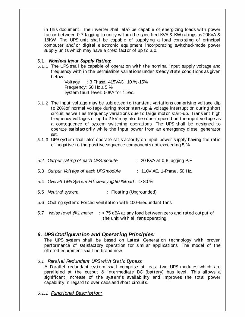
in this document. The inverter shall also be capable of energizing loads with power factor between 0.7 lagging to unity within the specified KVA & KW ratings as 20KVA & 16KW. The UPS unit shall be capable of supplying a load consisting of principal computer and/or digital electronic equipment incorporating switched-mode power supply units which may have a crest factor of up to 3.0.
5.1 Nominal Input Supply Rating: 5.1.1 The UPS shall be capable of operation with the nominal input supply voltage and
frequency with in the permissible variations under steady state conditions as given below:
Voltage : 3 Phase, 415VAC +10 %,-15% Frequency: 50 Hz ± 5 %. System fault level: 50KA for 1 Sec.
5.1.2 The input voltage may be subjected to transient variations comprising voltage dip to 20% of normal voltage during motor start-up & voltage interruption during short circuit as well as frequency variations due to large motor start-up. Transient high frequency voltages of up to 2 kV may also be superimposed on the input voltage as a consequence of system switching operations. The UPS shall be designed to operate satisfactorily while the input power from an emergency diesel generator set.
5.1.3 UPS system shall also operate satisfactorily on input power supply having the ratio of negative to the positive sequence components not exceeding 5 %.
5.2 Output rating of each UPS module : 20 KVA at 0.8 lagging P.F 5.3 Output Voltage of each UPS module : 110V AC, 1-Phase, 50 Hz. 5.4 Overall UPS System Efficiency @ 50 % load : > 80 %. 5.5 Neutral system : Floating (Ungrounded) 5.6 Cooling system: Forced ventilation with 100% redundant fans. 5.7 Noise level @ 1 meter : < 75 dBA at any load between zero and rated output of the unit with all fans operating. 6. UPS Configuration and Operating Principles:
The UPS system shall be based on Latest Generation technology with proven performance of satisfactory operation for similar applications. The model of the offered equipment shall be brand new.
6.1 Parallel Redundant UPS with Static Bypass:
A Parallel redundant system shall comprise at least two UPS modules which are paralleled at the output & intermediate DC (battery) bus level. This allows a significant increase of the system’s availability and improves the total power capability in regard to overloads and short circuits.
6.1.1 Functional Description:
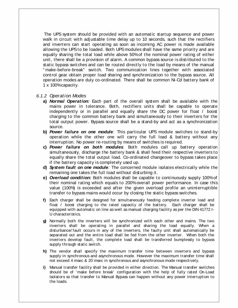
The UPS system should be provided with an automatic startup sequence and power walk in circuit with adjustable time delay up to 10 seconds, such that the rectifiers and inverters can start operating as soon as incoming AC power is made available allowing the UPS to be loaded. Both UPS modules shall have the same priority and are equally sharing the total load while above 50% of the nominal power rating of either unit, there shall be a provision of alarm. A common bypass source is distributed to the static bypass switches and can be routed directly to the load by means of the manual “make-before-break” switch. Two communication lines together with associated control gear obtain proper load sharing and synchronization to the bypass source. All operation modes are duly co-ordinated. There shall be common Ni-Cd battery bank of 1 x 100% capacity.
6.1.2 Operation Modes
a) Normal Operation: Each part of the overall system shall be available with the mains power in tolerance. Both, rectifiers units shall be capable to operate independently or in parallel and equally share the DC power for float / boost charging to the common battery bank and simultaneously to their inverters for the total output power. Bypass source shall be a stand-by and act as a synchronization source.
b) Power failure on one module: This particular UPS module switches to stand-by operation while the other one will carry the full load & battery without any interruption. No power re-routing by means of switches is required.
c) Power failure on both modules: Both modules call up battery operation simultaneously, discharge the battery bank & shall feed their respective inverters to equally share the total output load. Co-ordinated changeover to bypass takes place if the battery capacity is completely used up.
d) System fault on one module: The concerned module isolates electrically while the remaining one takes the full load without disturbing it.
e) Overload condition: Both modules shall be capable to continuously supply 100% of their nominal rating which equals to 200% overall power performance. In case this value (100%) is exceeded and after the given overload profile an uninterruptible transfer to bypass mains would occur by closing the static bypass switches.
f) Each charger shall be designed for simultaneously feeding complete inverter load and float / boost charging to the rated capacity of the battery. Each charger shall be equipped with automatic on line as well as manual charging facility as per the DIN 41772 I-U characteristics.
g) Normally both the inverters will be synchronized with each other and mains. The two inverters shall be operating in parallel and sharing the load equally. When a disturbance/fault occurs in any of the inverters, the faulty unit shall automatically be separated out and the entire load shall be fed from the other inverter. When both the inverters develop fault, the complete load shall be transferred bumplessly to bypass supply through static switch.
h) The vendor shall specify the maximum transfer time between inverters and bypass supply in synchronous and asynchronous mode. However the maximum transfer time shall not exceed 4 msec & 20 msec in synchronous and asynchronous mode respectively.
i) Manual transfer facility shall be provided in either direction. The Manual transfer switches should be of ‘make before break’ configuration with the help of fully rated On-Load Isolators so that transfer to Manual Bypass can happen without any power interruption to the loads.
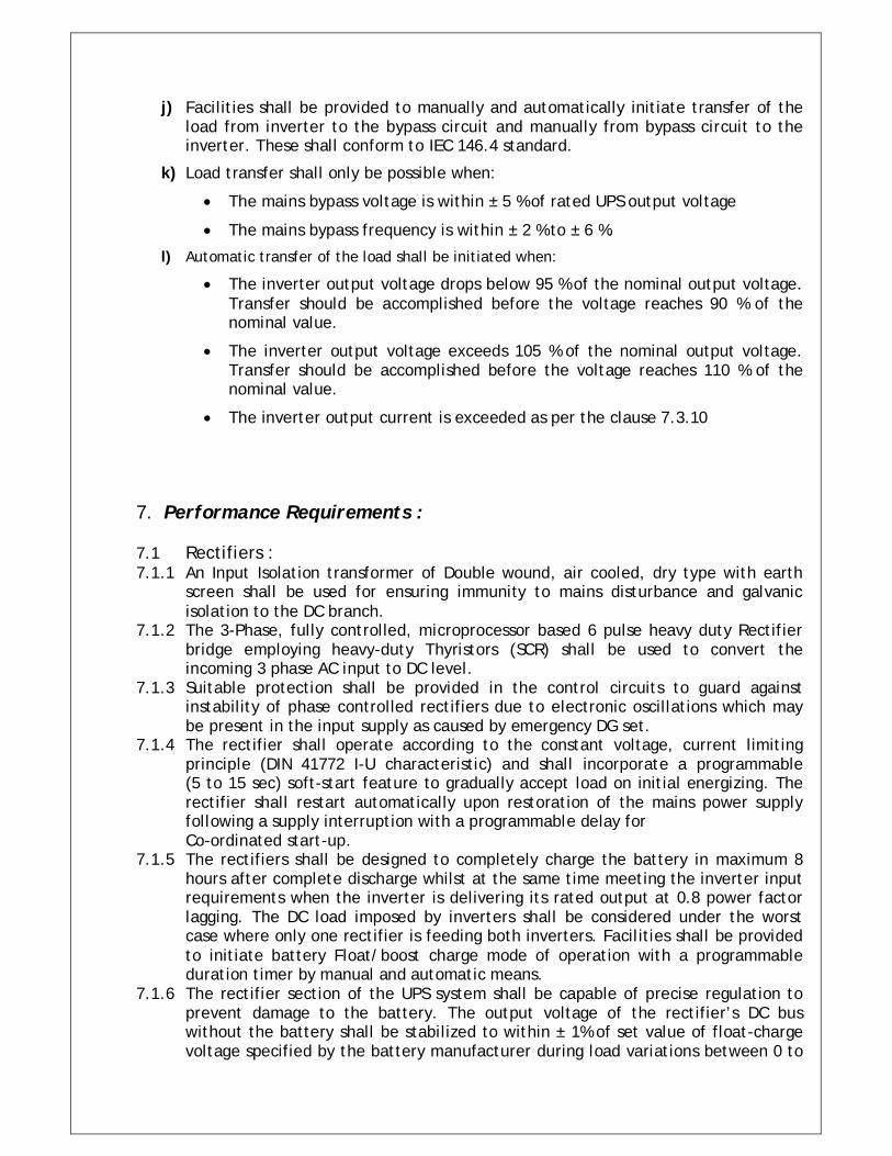
j) Facilities shall be provided to manually and automatically initiate transfer of the load from inverter to the bypass circuit and manually from bypass circuit to the inverter. These shall conform to IEC 146.4 standard.
k) Load transfer shall only be possible when:
The mains bypass voltage is within ± 5 % of rated UPS output voltage
The mains bypass frequency is within ± 2 % to ± 6 %.
l) Automatic transfer of the load shall be initiated when:
The inverter output voltage drops below 95 % of the nominal output voltage. Transfer should be accomplished before the voltage reaches 90 % of the nominal value.
The inverter output voltage exceeds 105 % of the nominal output voltage. Transfer should be accomplished before the voltage reaches 110 % of the nominal value.
The inverter output current is exceeded as per the clause 7.3.10
7. Performance Requirements : 7.1 Rectifiers : 7.1.1 An Input Isolation transformer of Double wound, air cooled, dry type with earth
screen shall be used for ensuring immunity to mains disturbance and galvanic isolation to the DC branch.
7.1.2 The 3-Phase, fully controlled, microprocessor based 6 pulse heavy duty Rectifier bridge employing heavy-duty Thyristors (SCR) shall be used to convert the incoming 3 phase AC input to DC level.
7.1.3 Suitable protection shall be provided in the control circuits to guard against instability of phase controlled rectifiers due to electronic oscillations which may be present in the input supply as caused by emergency DG set.
7.1.4 The rectifier shall operate according to the constant voltage, current limiting principle (DIN 41772 I-U characteristic) and shall incorporate a programmable (5 to 15 sec) soft-start feature to gradually accept load on initial energizing. The rectifier shall restart automatically upon restoration of the mains power supply following a supply interruption with a programmable delay for Co-ordinated start-up.
7.1.5 The rectifiers shall be designed to completely charge the battery in maximum 8 hours after complete discharge whilst at the same time meeting the inverter input requirements when the inverter is delivering its rated output at 0.8 power factor lagging. The DC load imposed by inverters shall be considered under the worst case where only one rectifier is feeding both inverters. Facilities shall be provided to initiate battery Float/boost charge mode of operation with a programmable duration timer by manual and automatic means.
7.1.6 The rectifier section of the UPS system shall be capable of precise regulation to prevent damage to the battery. The output voltage of the rectifier’s DC bus without the battery shall be stabilized to within ± 1% of set value of float-charge voltage specified by the battery manufacturer during load variations between 0 to
100% of the rated output of the rectifiers and specified mains input supply voltage variation.
7.1.7 A separate adjustable current limit circuit shall be provided for battery charging current. Subsequent to a discharge cycle when battery is connected to rectifier the battery current shall be monitored, controlled and limited to set value automatically irrespective of value of inverter input current.
7.1.8 For Ni-Cd batteries, the rectifier shall perform battery charging in accordance with the operational stipulations of the battery supplier and high rate charge facilities shall be interlockable. Also the rectifier shall be capable of delivering the battery initial charge as specified by the battery supplier; the inverter may be disconnected during the initial charging of the batteries.
7.1.9 Rectifier shall be so designed as to ensure that the total harmonic distortion in the input current to rectifiers as seen by the supply source Bus shall not exceed 28% of the fundamental current for 6-pulse.
7.1.10 Transients and surges on the mains input shall not result in a trip of the rectifier unit or the initiation of battery discharge. A suitable Transient Voltage Surge Suppressor (TVSS) shall be provided in the input circuit to the Rectifiers to protect the UPS system from surges. The TVSS should be sized to category B as per IEEEC62.41, parallel connected, should have all 10 mode protection (L-L, L-N, L-G, N-G) having surge withstand capability of 50KA and fault withstand capability of 50KA. It should clamp down the surges to within 800 Volts peak and have response time less than 0.5 nano seconds. It should be UL 1449 listed.
7.1.11 Suitable protection shall be provided in the control circuits to guard against instability of phase controlled rectifiers due to any electrical oscillations that may be present in the input supply. Also suitable DC earth leakage protection shall be provided in the UPS.
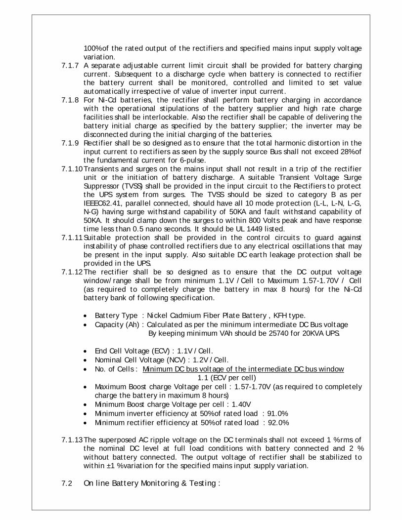
7.1.12 The rectifier shall be so designed as to ensure that the DC output voltage window/range shall be from minimum 1.1V /Cell to Maximum 1.57-1.70V / Cell (as required to completely charge the battery in max 8 hours) for the Ni-Cd battery bank of following specification.
Battery Type : Nickel Cadmium Fiber Plate Battery , KFH type. Capacity (Ah) : Calculated as per the minimum intermediate DC Bus voltage By keeping minimum VAh should be 25740 for 20KVA UPS. End Cell Voltage (ECV) : 1.1V /Cell. Nominal Cell Voltage (NCV) : 1.2V /Cell. No. of Cells : Minimum DC bus voltage of the intermediate DC bus window
1.1 (ECV per cell) Maximum Boost charge Voltage per cell : 1.57-1.70V (as required to completely
charge the battery in maximum 8 hours) Minimum Boost charge Voltage per cell : 1.40V Minimum inverter efficiency at 50% of rated load : 91.0% Minimum rectifier efficiency at 50% of rated load : 92.0%
7.1.13 The superposed AC ripple voltage on the DC terminals shall not exceed 1 % rms of
the nominal DC level at full load conditions with battery connected and 2 % without battery connected. The output voltage of rectifier shall be stabilized to within ±1 % variation for the specified mains input supply variation.
7.2 On line Battery Monitoring & Testing :
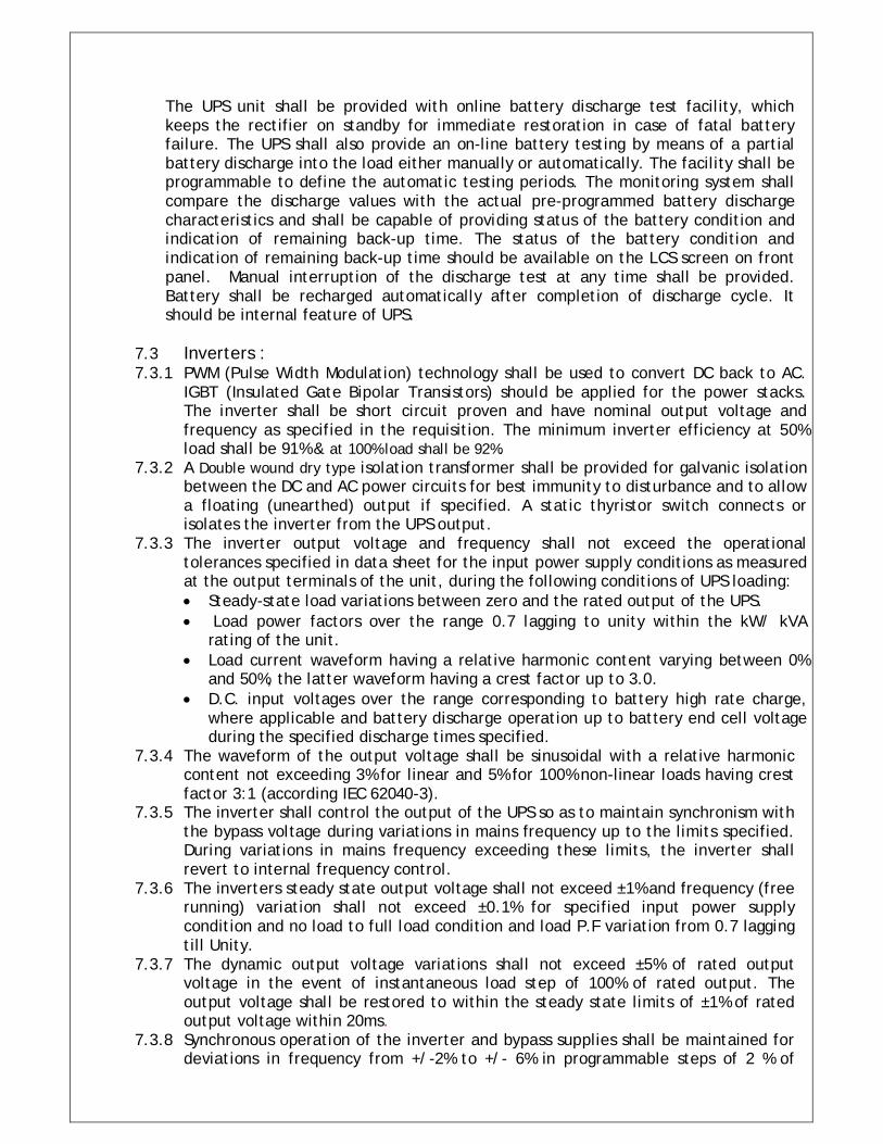
The UPS unit shall be provided with online battery discharge test facility, which keeps the rectifier on standby for immediate restoration in case of fatal battery failure. The UPS shall also provide an on-line battery testing by means of a partial battery discharge into the load either manually or automatically. The facility shall be programmable to define the automatic testing periods. The monitoring system shall compare the discharge values with the actual pre-programmed battery discharge characteristics and shall be capable of providing status of the battery condition and indication of remaining back-up time. The status of the battery condition and indication of remaining back-up time should be available on the LCS screen on front panel. Manual interruption of the discharge test at any time shall be provided. Battery shall be recharged automatically after completion of discharge cycle. It should be internal feature of UPS.
7.3 Inverters : 7.3.1 PWM (Pulse Width Modulation) technology shall be used to convert DC back to AC.
IGBT (Insulated Gate Bipolar Transistors) should be applied for the power stacks. The inverter shall be short circuit proven and have nominal output voltage and frequency as specified in the requisition. The minimum inverter efficiency at 50% load shall be 91% & at 100% load shall be 92%.
7.3.2 A Double wound dry type isolation transformer shall be provided for galvanic isolation between the DC and AC power circuits for best immunity to disturbance and to allow a floating (unearthed) output if specified. A static thyristor switch connects or isolates the inverter from the UPS output.
7.3.3 The inverter output voltage and frequency shall not exceed the operational tolerances specified in data sheet for the input power supply conditions as measured at the output terminals of the unit, during the following conditions of UPS loading: Steady-state load variations between zero and the rated output of the UPS. Load power factors over the range 0.7 lagging to unity within the kW/ kVA
rating of the unit. Load current waveform having a relative harmonic content varying between 0%
and 50%, the latter waveform having a crest factor up to 3.0. D.C. input voltages over the range corresponding to battery high rate charge,
where applicable and battery discharge operation up to battery end cell voltage during the specified discharge times specified.
7.3.4 The waveform of the output voltage shall be sinusoidal with a relative harmonic content not exceeding 3% for linear and 5% for 100% non-linear loads having crest factor 3:1 (according IEC 62040-3).
7.3.5 The inverter shall control the output of the UPS so as to maintain synchronism with the bypass voltage during variations in mains frequency up to the limits specified. During variations in mains frequency exceeding these limits, the inverter shall revert to internal frequency control.
7.3.6 The inverters steady state output voltage shall not exceed ±1% and frequency (free running) variation shall not exceed ±0.1% for specified input power supply condition and no load to full load condition and load P.F variation from 0.7 lagging till Unity.
7.3.7 The dynamic output voltage variations shall not exceed ±5% of rated output voltage in the event of instantaneous load step of 100% of rated output. The output voltage shall be restored to within the steady state limits of ±1% of rated output voltage within 20ms.
7.3.8 Synchronous operation of the inverter and bypass supplies shall be maintained for deviations in frequency from +/-2% to +/- 6% in programmable steps of 2 % of
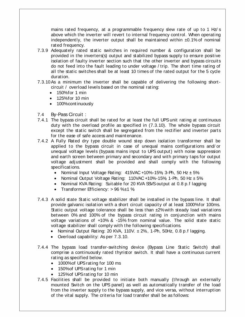
mains rated frequency, at a programmable frequency slew rate of up to 1 Hz/s above which the inverter will revert to internal frequency control. When operating independently, the inverter output shall be maintained within ±0.1% of nominal rated frequency.
7.3.9 Adequately rated static switches in required number & configuration shall be provided in the inverters(s) output and stabilized bypass supply to ensure positive isolation of faulty inverter section such that the other inverter and bypass circuits do not feed into the fault leading to under voltage /trip. The short time rating of all the static switches shall be at least 10 times of the rated output for the 5 cycle duration.
7.3.10 As a minimum the inverter shall be capable of delivering the following short-circuit / overload levels based on the nominal rating: 150% for 1 min 125% for 10 min 100% continuously
7.4 By-Pass Circuit : 7.4.1 The bypass circuit shall be rated for at least the full UPS unit rating at continuous
duty with the overload profile as specified in (7.3.10). The whole bypass circuit except the static switch shall be segregated from the rectifier and inverter parts for the ease of safe access and maintenance.
7.4.2 A Fully Rated dry type double wound step down isolation transformer shall be applied to the bypass circuit in case of unequal mains configurations and/or unequal voltage levels (bypass mains input to UPS output) with noise suppression and earth screen between primary and secondary and with primary taps for output voltage adjustment shall be provided and shall comply with the following specifications. Nominal Input Voltage Rating: 415VAC +10% -15%, 3-Ph, 50 Hz ± 5%. Nominal Output Voltage Rating: 110VAC +10% -15%, 1-Ph, 50 Hz ± 5%. Nominal KVA Rating: Suitable for 20 KVA SSVS output at 0.8 p.f lagging Transformer Efficiency: > 96 % ±1 %.
7.4.3 A solid state Static voltage stabilizer shall be installed in the bypass line. It shall
provide galvanic isolation with a short circuit capacity of at least 1000% for 100ms. Static output voltage tolerance shall be less than ±2% with steady load variations between 0% and 100% of the bypass circuit rating in conjunction with mains voltage variations of +10% & -15% from nominal value. The solid state static voltage stabilizer shall comply with the following specifications. Nominal Output Rating: 20 KVA, 110V. ± 2%., 1-Ph, 50Hz, 0.8 p.f lagging. Overload capability: As per 7.3.10.
7.4.4 The bypass load transfer-switching device (Bypass Line Static Switch) shall
comprise a continuously rated thyristor switch. It shall have a continuous current rating as specified below. 1000% of UPS rating for 100 ms 150% of UPS rating for 1 min 125% of UPS rating for 10 min
7.4.5 Facilities shall be provided to initiate both manually (through an externally mounted Switch on the UPS panel) as well as automatically transfer of the load from the inverter supply to the bypass supply, and vice versa, without interruption of the vital supply. The criteria for load transfer shall be as follows:
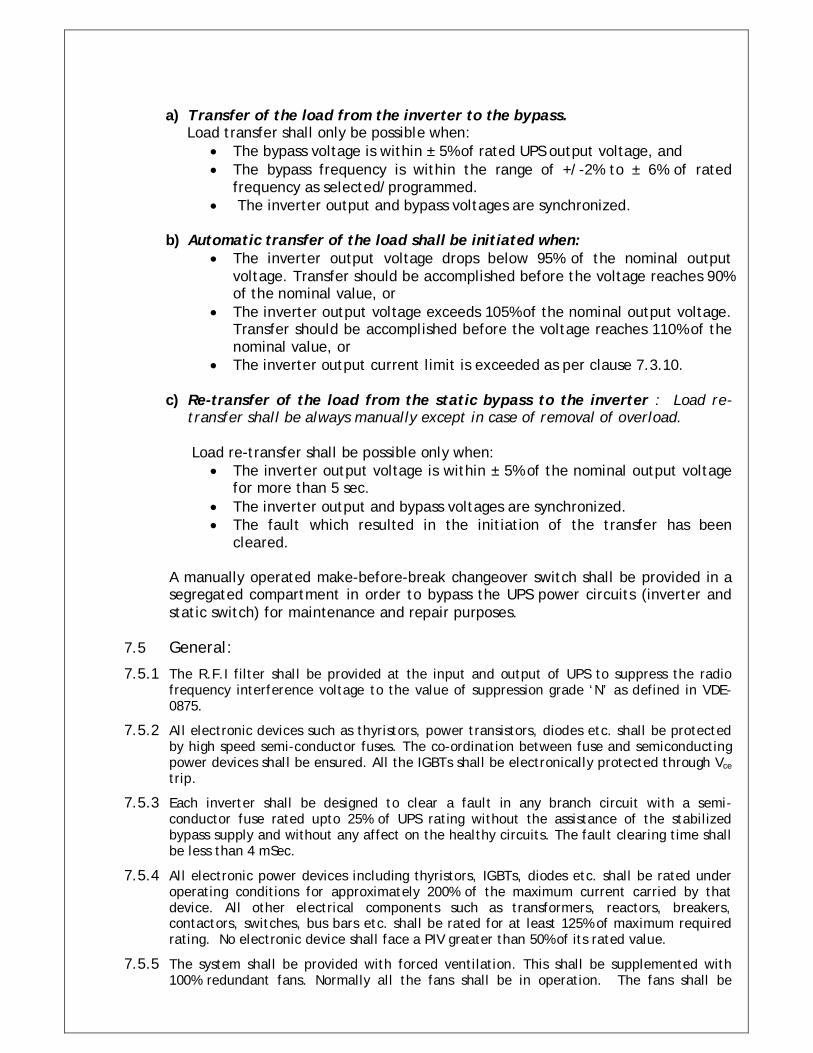
a) Transfer of the load from the inverter to the bypass.
Load transfer shall only be possible when: The bypass voltage is within ± 5% of rated UPS output voltage, and The bypass frequency is within the range of +/-2% to ± 6% of rated
frequency as selected/programmed. The inverter output and bypass voltages are synchronized.
b) Automatic transfer of the load shall be initiated when:
The inverter output voltage drops below 95% of the nominal output voltage. Transfer should be accomplished before the voltage reaches 90% of the nominal value, or
The inverter output voltage exceeds 105% of the nominal output voltage. Transfer should be accomplished before the voltage reaches 110% of the nominal value, or
The inverter output current limit is exceeded as per clause 7.3.10.
c) Re-transfer of the load from the static bypass to the inverter : Load re-transfer shall be always manually except in case of removal of overload.
Load re-transfer shall be possible only when:
The inverter output voltage is within ± 5% of the nominal output voltage for more than 5 sec.
The inverter output and bypass voltages are synchronized. The fault which resulted in the initiation of the transfer has been
cleared.
A manually operated make-before-break changeover switch shall be provided in a segregated compartment in order to bypass the UPS power circuits (inverter and static switch) for maintenance and repair purposes.
7.5 General:
7.5.1 The R.F.I filter shall be provided at the input and output of UPS to suppress the radio frequency interference voltage to the value of suppression grade ‘N’ as defined in VDE-0875.
7.5.2 All electronic devices such as thyristors, power transistors, diodes etc. shall be protected by high speed semi-conductor fuses. The co-ordination between fuse and semiconducting power devices shall be ensured. All the IGBTs shall be electronically protected through Vce trip.
7.5.3 Each inverter shall be designed to clear a fault in any branch circuit with a semi-conductor fuse rated upto 25% of UPS rating without the assistance of the stabilized bypass supply and without any affect on the healthy circuits. The fault clearing time shall be less than 4 mSec.
7.5.4 All electronic power devices including thyristors, IGBTs, diodes etc. shall be rated under operating conditions for approximately 200% of the maximum current carried by that device. All other electrical components such as transformers, reactors, breakers, contactors, switches, bus bars etc. shall be rated for at least 125% of maximum required rating. No electronic device shall face a PIV greater than 50% of its rated value.
7.5.5 The system shall be provided with forced ventilation. This shall be supplemented with 100% redundant fans. Normally all the fans shall be in operation. The fans shall be
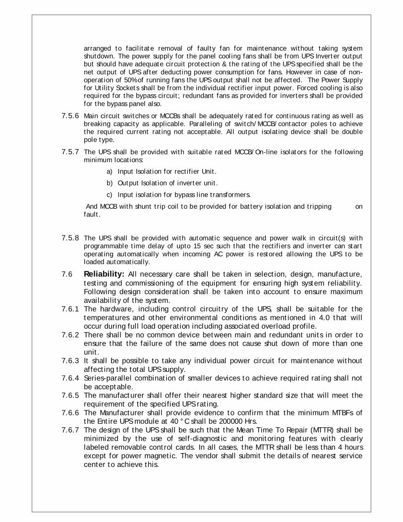
arranged to facilitate removal of faulty fan for maintenance without taking system shutdown. The power supply for the panel cooling fans shall be from UPS Inverter output but should have adequate circuit protection & the rating of the UPS specified shall be the net output of UPS after deducting power consumption for fans. However in case of non-operation of 50% of running fans the UPS output shall not be affected. The Power Supply for Utility Sockets shall be from the individual rectifier input power. Forced cooling is also required for the bypass circuit; redundant fans as provided for inverters shall be provided for the bypass panel also.
7.5.6 Main circuit switches or MCCBs shall be adequately rated for continuous rating as well as breaking capacity as applicable. Paralleling of switch/MCCB/contactor poles to achieve the required current rating not acceptable. All output isolating device shall be double pole type.
7.5.7 The UPS shall be provided with suitable rated MCCB/On-line isolators for the following minimum locations:
a) Input Isolation for rectifier Unit.
b) Output Isolation of inverter unit.
c) Input isolation for bypass line transformers.
And MCCB with shunt trip coil to be provided for battery isolation and tripping on fault.
7.5.8 The UPS shall be provided with automatic sequence and power walk in circuit(s) with programmable time delay of upto 15 sec such that the rectifiers and inverter can start operating automatically when incoming AC power is restored allowing the UPS to be loaded automatically.
7.6 Reliability: All necessary care shall be taken in selection, design, manufacture, testing and commissioning of the equipment for ensuring high system reliability. Following design consideration shall be taken into account to ensure maximum availability of the system.
7.6.1 The hardware, including control circuitry of the UPS, shall be suitable for the temperatures and other environmental conditions as mentioned in 4.0 that will occur during full load operation including associated overload profile.
7.6.2 There shall be no common device between main and redundant units in order to ensure that the failure of the same does not cause shut down of more than one unit.
7.6.3 It shall be possible to take any individual power circuit for maintenance without affecting the total UPS supply.
7.6.4 Series-parallel combination of smaller devices to achieve required rating shall not be acceptable.
7.6.5 The manufacturer shall offer their nearest higher standard size that will meet the requirement of the specified UPS rating.
7.6.6 The Manufacturer shall provide evidence to confirm that the minimum MTBFs of the Entire UPS module at 40 °C shall be 200000 Hrs.
7.6.7 The design of the UPS shall be such that the Mean Time To Repair (MTTR) shall be minimized by the use of self-diagnostic and monitoring features with clearly labeled removable control cards. In all cases, the MTTR shall be less than 4 hours except for power magnetic. The vendor shall submit the details of nearest service center to achieve this.
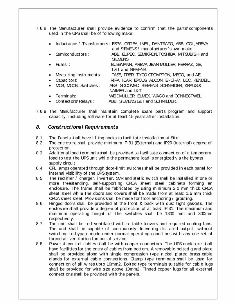
7.6.8 The Manufacturer shall provide evidence to confirm that the parts/components used in the UPS shall be of following make:
Inductance / Transformers : ESPA, ORTEA, IMEL, DANTRAFO, ABB, CGL,AREVA and SIEMENS / manufacturer’s own make. Semiconductors : ABB, EUPEC, SEMIKRON,TOSHIBA, MITSUBISHI and SIEMENS Fuses : BUSSMANN, AREVA,JEAN MÜLLER, FERRAZ, GE, L&T and SIEMENS. Measuring Instruments: FASE, FRER, TYCO CROMPTON, MECO, and AE. Capacitors: RIFA, ICAR, EPCOS, ALCON, El-Ci-Ar, LCC, KENDEIL. MCB, MCCB, Switches : ABB ,SOCOMEC, SIEMENS, SCHNEIDER, KRAUS & NAIMER and L&T. Terminals: WEIDMÜLLER, ELMEX, WAGO and CONNECTWEL. Contactors/Relays : ABB, SIEMENS,L&T and SCHNIEDER.
7.6.9 The Manufacturer shall maintain complete spare parts program and support capacity, including software for at least 15 years after installation.
8. Constructional Requirements 8.1 The Panels shall have lifting hooks to facilitate installation at Site. 8.2 The enclosure shall provide minimum IP-31 (External) and IP20 (internal) degree of
protection. 8.3 Additional load terminals shall be provided to facilitate connection of a temporary
load to test the UPS unit while the permanent load is energized via the bypass supply circuit.
8.4 CFL lamps operated through door-limit switches shall be provided in each panel for internal visibility of the UPS system.
8.5 The rectifier / charger, inverter, SVR and static switch shall be installed in one or more freestanding, self-supporting CRCA sheet steel cabinets forming an enclosure. The frame shall be fabricated by using minimum 2.0 mm thick CRCA sheet steel while the doors and covers shall be made from at least 1.6 mm thick CRCA sheet steel. Provisions shall be made for floor anchoring / grouting.
8.6 Hinged doors shall be provided at the front & back with dust tight gaskets. The enclosure shall provide a degree of protection of at least IP 31. The maximum and minimum operating height of the switches shall be 1800 mm and 300mm respectively.
8.7 The unit shall be self-ventilated with suitable louvers and required cooling fans. The unit shall be capable of continuously delivering its rated output, without switching to bypass mode under normal operating conditions with any one set of forced air ventilation fan out of service.
8.8 Power & control cables shall be with copper conductors. The UPS enclosure shall have facilities for the entry of cables from bottom. A removable bolted gland plate shall be provided along with single compression type nickel plated brass cable glands for external cable connections. Clamp type terminals shall be used for connection of all wires upto 10mm2. Bolted type terminals suitable for cable lugs shall be provided for wire size above 10mm2. Tinned copper lugs for all external connections shall be provided with the panels.
8.9 Bus bars shall be used in all power circuits which are rated above 100A. Copper conductor PVC insulated cables or wires of 660V grade shall be used for power circuits rated less than 100A.
8.10 All live terminals of door-mounted equipment having a maximum voltage of greater than 60 VDC or 42 VAC (60 V peak) shall be shrouded or otherwise protected by sufficient barriers to a degree of protection of atleast IP20.
8.11 All bare Bus bars shall be colour coded and live parts shall be provided with insulating sleeves and shall be shrouded or protected with suitable barriers to ensure complete safety to personnel intending routine inspection by opening the panel doors.
8.12 The maintenance bypass switch shall be so configured that it is completely electrically and mechanically segregated from the power electronics, static bypass switch and control circuitry.
8.13 Transformers and reactors shall be of the air-cooled type with Class H insulation. 8.14 An earth bar, with a suitable number of earthing bolts or screws, shall be
provided. The earth rail shall be connected to the structure of the cabinet, effectively bonding the entire cubicle. It shall be possible to connect at least two 25 mm² (AWG 3) earth cables to the earth rail for UPS units. Electrical conductivity between the exposed, non-current carrying conductive parts of the UPS components and the enclosure, and between the enclosure and the earth rail, shall be so arranged as to maintain effective and reliable continuity of the protective circuit.
8.15 All terminals and main components inside the cubicle and all door mounted components shall be identified by suitable labels secured appropriately with the name and device tag numbers in English text as per the schematic diagram/ Manufacturer's drawings. Terminals of input and output supply cables shall be clearly and uniquely marked to indicate their purpose and the phase/polarity of the supply. All wires shall be marked according to the electrical diagrams.
8.16 The panels shall be spray painted with two coats of epoxy-based paint or shall be
powder coated. Spray painted finished panels shall be dried in stoving ovens in a dust free atmosphere. Panel finish shall be free from imperfections like pinholes, orange peels. Runoff paint, etc.
8.17 The following information shall be inscribed on a non-destructive, corrosion-resistant, indelible name/rating plate attached to the inner side of the unit enclosure door: GAIL's order number Year of manufacture Name of Manufacturer Rating of UPS Type and serial number of unit Nominal input current and voltage Rated nominal output current and voltage Nominal DC / battery voltage Ingress protection degree Weight of the unit.
9. Measurement, Protection and Control Equipment 9.1 The UPS main controller shall be based on a multi-microprocessor architecture,
control and monitoring through a System front Panel, apart from soft touch Keys for turning On/Off the complete system and lamp test button for checking
functioning of all LED’s and shall include a System Mimic Diagram with LED type indications for the complete system in addition to a liquid crystal display (LCD) with a keypad driven menu for indication of the system operating status/diagnostics. Each LED/Alarm circuit with the exception of LED’s associated with PCB’s, shall have built-in test facilities with Audio-visual alarm on occurrence of any alarm/fault condition
9.2 Operating status and diagnostic indications shall be provided by liquid crystal
displays (LCD) with a keypad driven menu and light-emitting diodes (LED). Failure of an LED/LCD shall not cause UPS mal function or affect the correct functioning of the remote common alarm signal. Indication by means of filament lamps shall not be acceptable.
9.3 The following indications, in the form of LED/LCD and/or measuring instruments,
shall be provided on the front outside panel of the unit to enable verification of the operational status of the UPS. The indications shall be superimposed on a customized mimic diagram of the UPS to identify the relevant component or circuit. Additionally these indications should be available for remote signaling via the serial interface Rectifier input supply available / Rectifier ON Bypass supply available. Battery operation. Inverter ON. Load on inverter. Load on static bypass. Inverter/bypass not in Synch. Load on battery.
9.4 The following data at the minimum shall be provided on the front outside panel
via a menu driven LCD display. Also this information should be available for remote signaling via the communication interface: Rectifier Input Line Voltage per phase. Bypass line Input Voltage per phase. D.C. bus voltage. Battery charging current. Battery discharging current. UPS output Voltage/Current. UPS output frequency. Expected back-up time at every Battery operation cycle. Total Battery voltage during discharge.
9.5 The status of the Alarm and Protection functions shall be visually verifiable by
individual LED / LCD indicators. The following alarm and protection functions shall be provided as a minimum: Rectifier input out of tolerance alarm. Bypass voltage out of tolerance alarm Rectifier failure alarm D.C. over voltage alarm D.C. under voltage alarm Battery discharged alarm
Battery disconnected alarm Inverter failure alarm Inverter / static bypass overload alarm. Rectifier fuse failure alarm Inverter/bypass not synchronized alarm. Individual fan failure alarm through potential free contact. Power module over temperature alarm and delayed trip. Fault in internal power supply alarm. Load on maintenance bypass alarm. Earth fault on DC alarm
Two normally closed, potential free, changeover contacts with adjustable delay shall be provided for the common alarms. Also this information should be available for remote signaling / DCS through RS485 / MODBUS protocol situated at a distance of at least 200 meters from the UPS installation. The Communication Cables, Ports, Adapters as required along with necessary software shall be provided as an integral part of the complete package.
9.6 Comprehensive alarm and status indications shall be available through keypad
driven menus in addition to (9.5). All arisen alarms and changes in operation modes shall be time stamped and stored in a non-volatile memory whose capacity shall keep at least the last 50 entries in a “first in – first out” rolling manner.
9.7 Vendor has to ensure that no common component is used for achieving True
Redundancy. Control power sources shall be redundant having sensing from bypass supply as well as DC bus, failure of any control supply shall be indicated through LED on panel.
9.8 A keypad driven user menu shall contain at least the following:
Changeover between UPS and Bypass Supply. Battery discharge test. Battery diagnostic test. Battery Float/Boost Charging Mode Selection. Inverter output Voltage Adjustment: ±5%.
9.9 All voltage, current, and protective settings including calibration data shall be digitally stored in a nonvolatile memory.
9.10 Different password levels shall allow selective access to trained maintenance or service engineers.
10. Inspection and Testing: 10.1 The UPS Manufacturer shall furnish all necessary information concerning the supply
to GAIL. Tests shall be carried out at manufacturer’s works under his care and expense.
10.2 The UPS shall be tested in accordance with applicable standards. The Vendor shall submit to GAIL a detailed test schedule and test procedure for prior Approval. The Vendor shall also indicate the maximum allowable tolerance for each test result along with test procedures. All tests shall be witnessed by the GAIL representative and 4 weeks prior notice shall be given before the date of commencement of tests. If the tests show that certain requirements of specifications are not met,
vendor shall make necessary corrections to the equipment so that it satisfies all the requirements before acceptance is made.
10.3 The manufacturer shall submit a test report to GAIL, incorporating measurements and results of all tests performed in presence of GAIL representative.
10.4 UPS tests shall be confined to verifying the performance of the UPS unit and related auxiliaries. Tests to verify the capacity of the purchased battery shall be performed at the site of GAIL as part of the commissioning procedure after site erection.
10.5 Prior to the commencement of tests, the Manufacturer shall make all relevant adjustments to the protection and control circuit components of the UPS, as necessary to fulfill the requirements of the purchase order and this specification. The rectifier output voltage and current limits shall be set to the appropriate values for the type and number of battery cells to be supplied with the UPS.
10.6 Routines Tests: Each UPS system shall be tested in accordance with IEC 62040-3
and shall include the following tests as a minimum. a) Insulation Tests: Insulation tests shall be performed for Control / Power
Electronics and Auxiliary Circuits of the Complete UPS System as per IEC60146-1-1.
b) Interconnection cable check: The interconnection cables are to be checked for correct wiring, insulation and quality of the terminations.
c) A.C input failure test: The test is performed with the test battery and carried out by tripping A.C incoming circuit breaker or switching off rectifiers and bypass supply at the same time. Output voltage and frequency variations are to be checked for specified limits.
d) A.C input return test: The test is performed by closing A.C incoming circuit breaker or is simulated by energizing rectifiers and bypass supply. Proper operation of rectifiers starting and voltage and frequency variations are to be checked.
e) Simulation of parallel redundant UPS fault: The test is applicable for UPS with parallel redundant configuration. Fault of rectifier or inverter are to be simulated and output transients are to be recorded.
f) Transfer test: Transient shall be measured during load transfer from inverter to bypass supply caused by simulated fault and load transfer after clearing the fault.
g) Regulation test: The test shall be carried out by measuring input voltage, input current, output voltage, output current, Intermediate DC bus voltage, output distortion, input active power and frequency at No-Load, 50% load and 100% load at the lagging P.F of 0.7 to 0.8. Following parameters of rectifiers and inverters are to be measured:
I. Measurement shall be carried out in the rectifier float charge & rapid
charge mode. Measurement shall be at nominal AC voltage and at No-load, 50% load and 100% of rectifier full load. Rectifier measurement shall comprise of :
Input voltage, frequency, phase current and input power. DC output voltage & current. Ripple current at the link bus shall be recorded after isolating the test
battery. II. Inverter measurement shall be at No-load, 50% load and 100% load of
inverter rated output current and shall be repeated for inverter DC input

voltage corresponding to battery float charge operation as well as rated inverter maximum and minimum input DC Voltage. Measurement shall comprise of :
Input voltage and Input current. Output voltage, frequency & wave form distortion, Output current & power.
h) UPS efficiency: This shall be determined by the measurement of the active input & output power at rated P.F for 50%, 75% and 100% load.
i) Current division in parallel UPS: Load sharing between UPS units shall be measured with dummy load under parallel redundant UPS configuration.
j) Light load test: the test is to verify that all functions of the UPS system operate properly at some low percentage of the rated UPS capacity. The following points are to be checked. I. Output voltage and frequency and correct operation of meters. II. Operations of all control switches and other means to put UPS system in
operation. III. Functioning of protective & warning devices.
k) Built-in test for Printed Circuit Boards: PCBs and other electronic components
sub assemblies shall undergo a burn-in test for 96 hours at 500 C at a voltage varied between the maximum & minimum supply voltage. In case of failure of any component during testing, the test shall be repeated after replacement of the faulty components.
l) Continuous full load test at 0.8 P.F: The test is required to be performed by connecting resistive & inductive load to the UPS system output. The UPS shall undergo a complete full load test for 32 hours at 0.8 P.F. out of these 32 hours, each inverter section shall be subjected to full load test for 8 hours, both inverters sections operating in parallel shall be subjected to full load test for 8 hours and the for remaining 8 hours, the by pass section shall be subjected to full load test. Steady state temperature of rectifier transformer, rectifier set, D.C choke, inverter set, static switch etc shall be recorded during the test. The temperatures of all UPS panels are also to be recorded.
m) Auxiliary equipment and control circuit tests: the correct functioning of all measuring equipments, alarms, indications, protection devices and controls are to be verified. The functioning of auxiliary devices such as lighting, cooling fans, annunciation etc. should be checked.
n) Synchronization test: Frequency variation limits of inverter is to be tested by feeding bypass supply incoming line by variable frequency generator and inverter synchronization limit is to be checked as specified.
o) Overload capability test: Specified values of short time overload are to be applied for specified time interval. Values of output voltage and output current are to be recorded.
p) Short circuit current capability test: Specified short circuit current capability is to be tested by application of a short circuit to UPS output if necessary via suitable fuse. Short circuit current is to be recorded.
q) Short circuit fuse test: Fuse tripping capability of the UPS system is to be tested by the short circuiting the UPS system output via a specified rating of fuse. The test is carried out at an appropriate UPS load under normal operation.
r) Restart: Manual restart to be tested after complete shut down of UPS system.
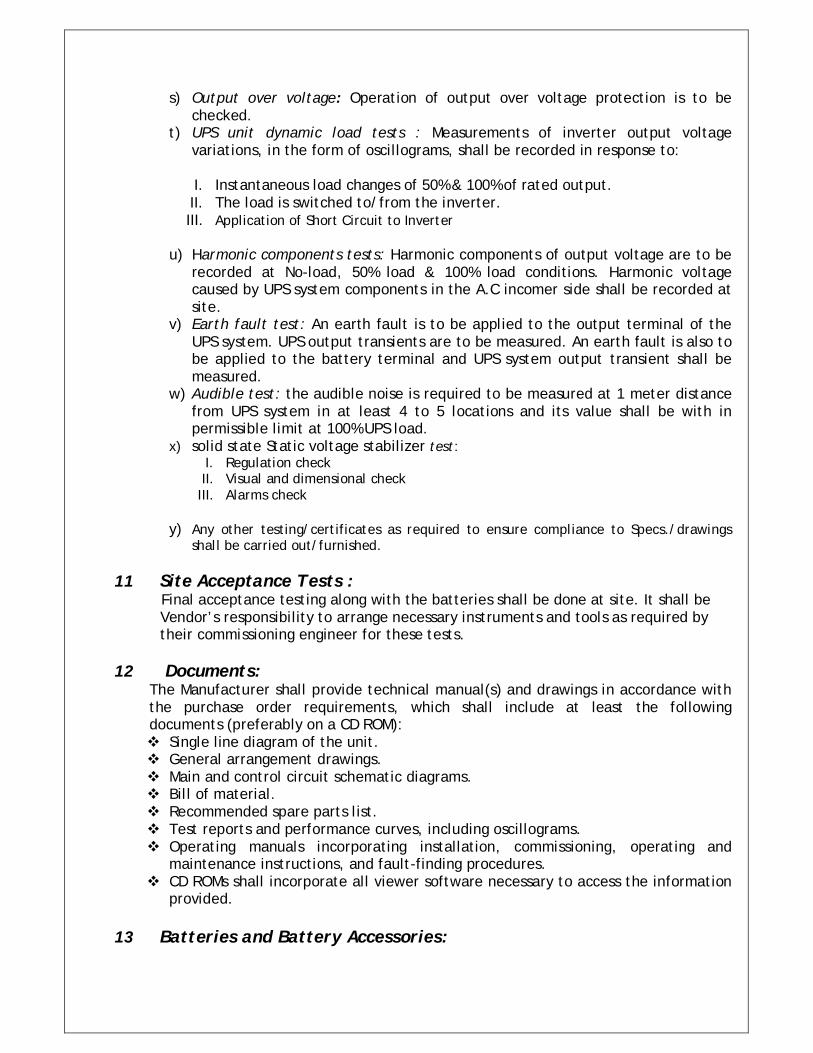
s) Output over voltage: Operation of output over voltage protection is to be checked.
t) UPS unit dynamic load tests : Measurements of inverter output voltage variations, in the form of oscillograms, shall be recorded in response to:
I. Instantaneous load changes of 50% & 100% of rated output. II. The load is switched to/from the inverter. III. Application of Short Circuit to Inverter
u) Harmonic components tests: Harmonic components of output voltage are to be
recorded at No-load, 50% load & 100% load conditions. Harmonic voltage caused by UPS system components in the A.C incomer side shall be recorded at site.
v) Earth fault test: An earth fault is to be applied to the output terminal of the UPS system. UPS output transients are to be measured. An earth fault is also to be applied to the battery terminal and UPS system output transient shall be measured.
w) Audible test: the audible noise is required to be measured at 1 meter distance from UPS system in at least 4 to 5 locations and its value shall be with in permissible limit at 100% UPS load.
x) solid state Static voltage stabilizer test: I. Regulation check II. Visual and dimensional check
III. Alarms check
y) Any other testing/certificates as required to ensure compliance to Specs./drawings shall be carried out/furnished.
11 Site Acceptance Tests : Final acceptance testing along with the batteries shall be done at site. It shall be Vendor’s responsibility to arrange necessary instruments and tools as required by their commissioning engineer for these tests.
12 Documents: The Manufacturer shall provide technical manual(s) and drawings in accordance with the purchase order requirements, which shall include at least the following documents (preferably on a CD ROM): Single line diagram of the unit. General arrangement drawings. Main and control circuit schematic diagrams. Bill of material. Recommended spare parts list. Test reports and performance curves, including oscillograms. Operating manuals incorporating installation, commissioning, operating and
maintenance instructions, and fault-finding procedures. CD ROMs shall incorporate all viewer software necessary to access the information
provided.
13 Batteries and Battery Accessories:
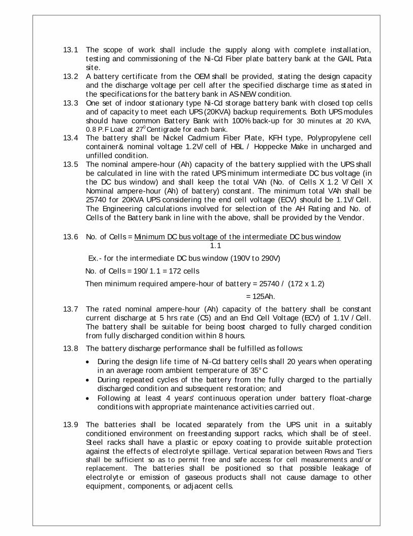
13.1 The scope of work shall include the supply along with complete installation, testing and commissioning of the Ni-Cd Fiber plate battery bank at the GAIL Pata site.
13.2 A battery certificate from the OEM shall be provided, stating the design capacity and the discharge voltage per cell after the specified discharge time as stated in the specifications for the battery bank in AS-NEW condition.
13.3 One set of indoor stationary type Ni-Cd storage battery bank with closed top cells and of capacity to meet each UPS (20KVA) backup requirements. Both UPS modules should have common Battery Bank with 100% back-up for 30 minutes at 20 KVA, 0.8 P.F Load at 270 Centigrade for each bank.
13.4 The battery shall be Nickel Cadmium Fiber Plate, KFH type, Polypropylene cell container& nominal voltage 1.2V/cell of HBL / Hoppecke Make in uncharged and unfilled condition.
13.5 The nominal ampere-hour (Ah) capacity of the battery supplied with the UPS shall be calculated in line with the rated UPS minimum intermediate DC bus voltage (in the DC bus window) and shall keep the total VAh (No. of Cells X 1.2 V/Cell X Nominal ampere-hour (Ah) of battery) constant. The minimum total VAh shall be 25740 for 20KVA UPS considering the end cell voltage (ECV) should be 1.1V/Cell. The Engineering calculations involved for selection of the AH Rating and No. of Cells of the Battery bank in line with the above, shall be provided by the Vendor.
13.6 No. of Cells = Minimum DC bus voltage of the intermediate DC bus window 1.1
Ex.- for the intermediate DC bus window (190V to 290V)
No. of Cells = 190/1.1 = 172 cells
Then minimum required ampere-hour of battery = 25740 / (172 x 1.2)
= 125Ah.
13.7 The rated nominal ampere-hour (Ah) capacity of the battery shall be constant current discharge at 5 hrs rate (C5) and an End Cell Voltage (ECV) of 1.1V /Cell. The battery shall be suitable for being boost charged to fully charged condition from fully discharged condition within 8 hours.
13.8 The battery discharge performance shall be fulfilled as follows:
During the design life time of Ni-Cd battery cells shall 20 years when operating in an average room ambient temperature of 35°C
During repeated cycles of the battery from the fully charged to the partially discharged condition and subsequent restoration; and
Following at least 4 years' continuous operation under battery float-charge conditions with appropriate maintenance activities carried out.
13.9 The batteries shall be located separately from the UPS unit in a suitably
conditioned environment on freestanding support racks, which shall be of steel. Steel racks shall have a plastic or epoxy coating to provide suitable protection against the effects of electrolyte spillage. Vertical separation between Rows and Tiers shall be sufficient so as to permit free and safe access for cell measurements and/or replacement. The batteries shall be positioned so that possible leakage of electrolyte or emission of gaseous products shall not cause damage to other equipment, components, or adjacent cells.
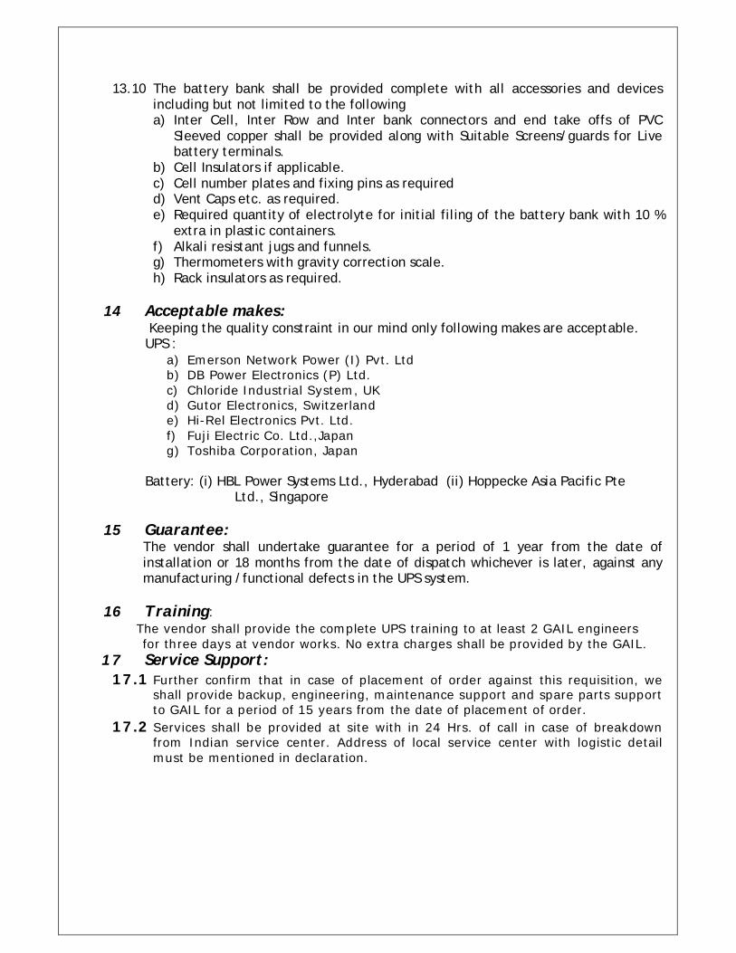
13.10 The battery bank shall be provided complete with all accessories and devices including but not limited to the following a) Inter Cell, Inter Row and Inter bank connectors and end take offs of PVC
Sleeved copper shall be provided along with Suitable Screens/guards for Live battery terminals.
b) Cell Insulators if applicable. c) Cell number plates and fixing pins as required d) Vent Caps etc. as required. e) Required quantity of electrolyte for initial filing of the battery bank with 10 %
extra in plastic containers. f) Alkali resistant jugs and funnels. g) Thermometers with gravity correction scale. h) Rack insulators as required.
14 Acceptable makes:
Keeping the quality constraint in our mind only following makes are acceptable. UPS :
a) Emerson Network Power (I) Pvt. Ltd b) DB Power Electronics (P) Ltd. c) Chloride Industrial System, UK d) Gutor Electronics, Switzerland e) Hi-Rel Electronics Pvt. Ltd. f) Fuji Electric Co. Ltd.,Japan g) Toshiba Corporation, Japan
Battery: (i) HBL Power Systems Ltd., Hyderabad (ii) Hoppecke Asia Pacific Pte
Ltd., Singapore
15 Guarantee: The vendor shall undertake guarantee for a period of 1 year from the date of installation or 18 months from the date of dispatch whichever is later, against any manufacturing /functional defects in the UPS system.
16 Training:
The vendor shall provide the complete UPS training to at least 2 GAIL engineers for three days at vendor works. No extra charges shall be provided by the GAIL.
17 Service Support: 17.1 Further confirm that in case of placement of order against this requisition, we
shall provide backup, engineering, maintenance support and spare parts support to GAIL for a period of 15 years from the date of placement of order.
17.2 Services shall be provided at site with in 24 Hrs. of call in case of breakdown from Indian service center. Address of local service center with logistic detail must be mentioned in declaration.
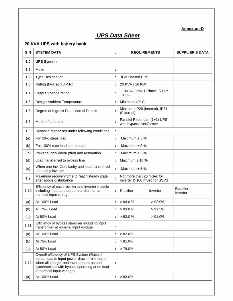
Annexure-D
UPS Data Sheet 20 KVA UPS with battery bank
S.N SYSTEM DATA : REQUIREMENTS SUPPLIER'S DATA
1.0 UPS System
1.1 Make :
1.2 Type Designation : IGBT based UPS
1.3 Rating (kVA at 0.8 P.F.) : 20 KVA / 16 KW
1.4 Output Voltage rating : 110V AC ±1%.1-Phase, 50 Hz ±0.1%.
1.5 Design Ambient Temperature : Minimum 40° C
1.6 Degree of Ingress Protection of Panels : Minimum IP20 (internal), IP31 (External)
1.7 Mode of operation : Parallel Redundant(1+1) UPS with bypass transformer
1.8 Dynamic responses under following conditions :
(a) For 50% steps load : Maximum ± 5 %
(b) For 100% step load and unload : Maximum ± 5 %
( c) Power supply interruption and restoration : Maximum ± 5 %
(d) Load transferred to bypass line : Maximum ± 10 %
(e) When one Inv. Gets faulty and load transferred to healthy inverter : Maximum ± 5 %
1.9 Maximum recovery time to reach steady state after above disturbance : Not more than 20 mSec for
inverter & 100 mSec for SSVS
1.10 Efficiency of each rectifier and inverter module including input and output transformer at nominal input voltage
: Rectifier Inverter Rectifier Inverter
(a) At 100% Load : > 94.0 % > 92.0%
(b) AT 75% Load : > 93.0 % > 91.5%
( c) At 50% Load : > 92.0 % > 91.0%
1.11 Efficiency of bypass stabiliser including input transformer at nominal input voltage :
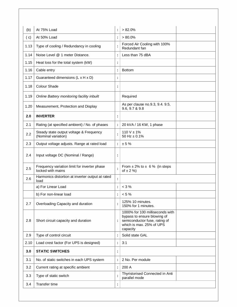
(a) At 100% Load : > 82.0%
(b) At 75% Load : > 81.0%
( c) At 50% Load : > 79.0%
1.12
Overall efficiency of UPS System (Ratio of output load to input power drawn from mains when all charger and inverters are on and synchronised with bypass operating at no load at nominal input voltage)
:
(a) At 100% Load : > 83.0%
(b) At 75% Load : > 82.0%
( c) At 50% Load : > 80.0%
1.13 Type of cooling / Redundancy in cooling : Forced Air Cooling with 100% Redundant fan
1.14 Noise Level @ 1 meter Distance. : Less than 75 dBA
1.15 Heat loss for the total system (kW) :
1.16 Cable entry : Bottom
1.17 Guaranteed dimensions (L x H x D) :
1.18 Colour Shade :
1.19 Online Battery monitoring facility inbuilt Required
1.20 Measurement, Protection and Display As per clause no.9.3, 9.4. 9.5, 9.6, 9.7 & 9.8
2.0 INVERTER :
2.1 Rating (at specified ambient) / No. of phases : 20 kVA / 16 KW, 1 phase
2.2 Steady state output voltage & Frequency (Nominal variation) : 110 V ± 1%
50 Hz ± 0.1%
2.3 Output voltage adjusts. Range at rated load : ± 5 %
2.4 Input voltage DC (Nominal / Range) :
2.5 Frequency variation limit for inverter phase locked with mains : From ± 2% to ± 6 % (in steps
of ± 2 %)
2.6 Harmonics distortion at inverter output at rated load :
a) For Linear Load : < 3 %
b) For non-linear load : < 5 %
2.7 Overloading Capacity and duration : 125% 10 minutes. 150% for 1 minutes.
2.8 Short circuit capacity and duration :
1000% for 100 milliseconds with bypass to ensure blowing of semiconductor fuse, rating of which is max. 25% of UPS capacity
2.9 Type of control circuit : Solid state GAL
2.10 Load crest factor (For UPS is designed) : 3:1
3.0 STATIC SWITCHES :
3.1 No. of static switches in each UPS system : 2 No. Per module
3.2 Current rating at specific ambient : 200 A
3.3 Type of static switch : Thyristorised Connected in Anti parallel mode
3.4 Transfer time :
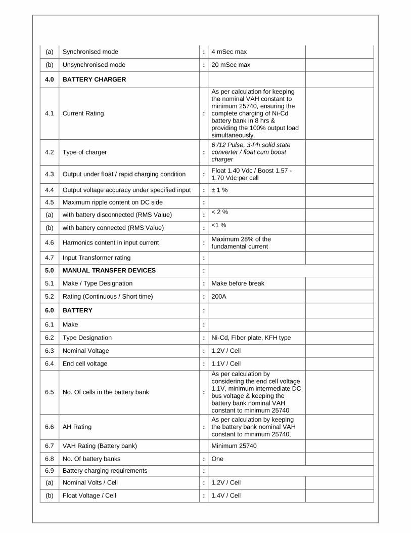
(a) Synchronised mode : 4 mSec max
(b) Unsynchronised mode : 20 mSec max
4.0 BATTERY CHARGER
4.1 Current Rating :
As per calculation for keeping the nominal VAH constant to minimum 25740, ensuring the complete charging of Ni-Cd battery bank in 8 hrs & providing the 100% output load simultaneously.
4.2 Type of charger : 6 /12 Pulse, 3-Ph solid state converter / float cum boost charger
4.3 Output under float / rapid charging condition : Float 1.40 Vdc / Boost 1.57 -1.70 Vdc per cell
4.4 Output voltage accuracy under specified input : ± 1 %
4.5 Maximum ripple content on DC side :
(a) with battery disconnected (RMS Value) : < 2 %
(b) with battery connected (RMS Value) : <1 %
4.6 Harmonics content in input current : Maximum 28% of the fundamental current
4.7 Input Transformer rating :
5.0 MANUAL TRANSFER DEVICES :
5.1 Make / Type Designation : Make before break
5.2 Rating (Continuous / Short time) : 200A
6.0 BATTERY :
6.1 Make :
6.2 Type Designation : Ni-Cd, Fiber plate, KFH type
6.3 Nominal Voltage : 1.2V / Cell
6.4 End cell voltage : 1.1V / Cell
6.5 No. Of cells in the battery bank :
As per calculation by considering the end cell voltage 1.1V, minimum intermediate DC bus voltage & keeping the battery bank nominal VAH constant to minimum 25740
6.6 AH Rating : As per calculation by keeping the battery bank nominal VAH constant to minimum 25740,
6.7 VAH Rating (Battery bank) Minimum 25740
6.8 No. Of battery banks : One
6.9 Battery charging requirements :
(a) Nominal Volts / Cell : 1.2V / Cell
(b) Float Voltage / Cell : 1.4V / Cell
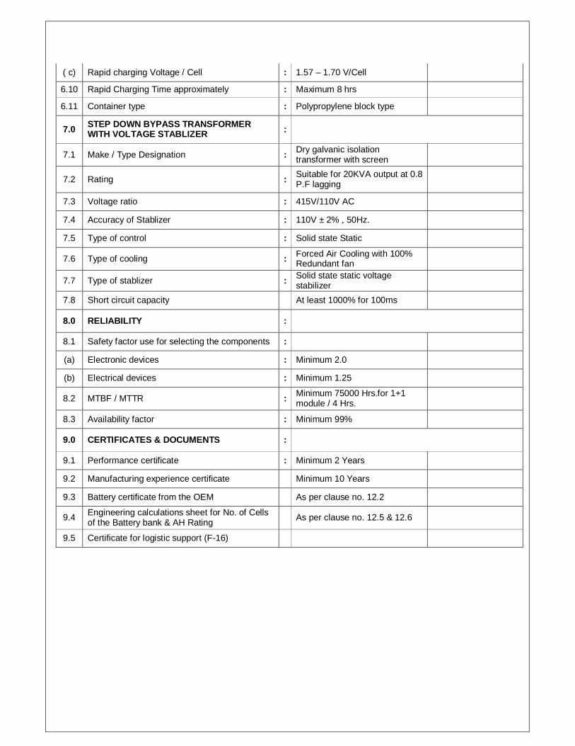
( c) Rapid charging Voltage / Cell : 1.57 – 1.70 V/Cell
6.10 Rapid Charging Time approximately : Maximum 8 hrs
6.11 Container type : Polypropylene block type
7.0 STEP DOWN BYPASS TRANSFORMER WITH VOLTAGE STABLIZER :
7.1 Make / Type Designation : Dry galvanic isolation transformer with screen
7.2 Rating : Suitable for 20KVA output at 0.8 P.F lagging
7.3 Voltage ratio : 415V/110V AC
7.4 Accuracy of Stablizer : 110V ± 2% , 50Hz.
7.5 Type of control : Solid state Static
7.6 Type of cooling : Forced Air Cooling with 100% Redundant fan
7.7 Type of stablizer : Solid state static voltage stabilizer
7.8 Short circuit capacity At least 1000% for 100ms
8.0 RELIABILITY :
8.1 Safety factor use for selecting the components :
(a) Electronic devices : Minimum 2.0
(b) Electrical devices : Minimum 1.25
8.2 MTBF / MTTR : Minimum 75000 Hrs.for 1+1 module / 4 Hrs.
8.3 Availability factor : Minimum 99%
9.0 CERTIFICATES & DOCUMENTS :
9.1 Performance certificate : Minimum 2 Years
9.2 Manufacturing experience certificate Minimum 10 Years
9.3 Battery certificate from the OEM As per clause no. 12.2
9.4 Engineering calculations sheet for No. of Cells of the Battery bank & AH Rating As per clause no. 12.5 & 12.6
9.5 Certificate for logistic support (F-16)