comparative study of commercial high …buildings on sloping ground and flat ground with flat slab....
TRANSCRIPT

International Research Journal of Engineering and Technology (IRJET) e-ISSN: 2395-0056
Volume: 04 Issue: 08 | Aug -2017 www.irjet.net p-ISSN: 2395-0072
© 2017, IRJET | Impact Factor value: 5.181 | ISO 9001:2008 Certified Journal | Page 2295
COMPARATIVE STUDY OF COMMERCIAL HIGH-RISE BUILDING WITH
FLAT SLAB BY VARYING SLOPE OF THE GROUND FOR DIFFERENT SOIL
AND SEISMIC ZONE CONDITION
RAGHAVENDRA M S1, SHILPA B S2, MANJUNATH C BHATTACHARYA3
1M.Tech. in Structural Engineering, East West Institute of Technology, Bengaluru, Karnataka, India. 2Assistant Professor, Dept. of Civil Engineering, East West Institute of Technology, Bengaluru, Karnataka, India.
3 Structural Design Engineer, Nadig consultancy private limited, Bengaluru, Karnataka, India. ---------------------------------------------------------------------***---------------------------------------------------------------------
Abstract - In a developing country like India there is a scarcity of land due to urbanization and industrialization, which led the way for construction of high rise multistorey buildings on hilly regions. Buildings constructed on hilly areas are different from the buildings constructed on flat grounds because of their irregularity and unsymmetrical structure in vertical and horizontal plane. Also, these buildings on hilly areas are much more prone to earthquake forces. The main objective of the present work is to study the behavior of the buildings on sloping ground and flat ground with flat slab. In this work an attempt has been made to study the behavior of the ongoing project which is a commercial building with conventional beam and slab in zonal level II, by considering it on different earthquake zones like zone III, IV and V and also for different soil type condition such as soil type 1, 2 and 3(Rock or hard soil, medium soil and soft soil). The comparison is made for flat ground building and sloped ground building with flat slabs. The sloping angles considered for the analysis are 0o, 20o and 30o.The models are prepared using ETABS structural analysis software and Dynamic analysis is done by following the procedure as per Indian code IS:1893-2002. The results of the analysis i.e., time period, displacement, moments, storey shear and storey drifts are tabulated and studied. Observing the results, we can say that performance of the building increases with increase in soil stiffness.
Key Words: Sloping Ground, Dynamic Analysis, Flat Slab, Sloping Angle, ETABS.
1. INTRODUCTION
Earth quakes are the common wonder's which are caused by the arrival of substantial strain energy by the moving faults underneath the surface of the earth, which eventually causes the shaking of the earth upper surface in all conceivable headings with various amplitudes and powers of lateral forces. Seismic tremor can be ordered relying upon the power of tremor, length and directions as minor, moderate and extreme and is measured on the Richter size scale. Anything above magnitude 7 is considered as serious sort of tremors. At the point when a structure is subjected to seismic constrains it doesn't make misfortune human lives straightforwardly yet because of the harm cause to the structures that prompts the fall of the building and consequently to the tenants and the property.
Despite the fact that the occurrences of quakes of ruinous power have been bound to a generally couple of territories of the world, the calamitous results of the few that have struck close focuses of population have worried on the need to give sufficient security against this most awful nature’s peculiarity. India had seen a few noteworthy calamities because of quakes over the previous century. Indeed, more than 50 percent of the nation is viewed as inclined to extreme quakes. The north - east locale of the nation and additionally the whole Himalayan belt is defenceless to extraordinary quakes of size greater than 8. The primary driver of seismic tremors in these districts is because of the development of the Indian plate towards the Eurasian plate at the rate of around 50 mm for every year.
The structures which are outlined and developed according to before code arrangement have not yet achieved prerequisites for show tremors. Hence a hefty portion of the structures in quake inclined zones are experiencing seismic dangers. Consequently, the new code arrangements are made for such cases. Multistoried R.C. confined structures are getting prominent in bumpy zones due to increment in arrive cost and in mandatory conditions. Along these lines the structures in the uneven regions ought to have sufficient quality to maintain a strategic distance from the disappointment of structure amid seismic tremors. Over half of our property is seismically inclined and is being gone by tremors on numerous occasions bringing about financial misfortunes in enormous extents and in the meantime helping us the need to remember quake safe plan.
2. LITERATURE REVIEWS
2.1 Review of selected Literature
1) Sujit Kumar et.al (2014)
In this journal, they studied the effect of sloping ground on structural performance of RCC building under Seismic load. They considered G+4 storey RCC building on varying slopes for the analysis. In this study, the slope angles considered for the analysis are 0o, 7.5o and 15o. STAAD Pro v8i is the structural analysis software used to study the effect of sloping ground by considering the seismic forces as per IS: 1893-2002. The parameters taken for the analysis are horizontal reactions, axial force and bending moment column and footing bending moment. They observed that because of increase in stiffness the shorter columns attract more forces,

International Research Journal of Engineering and Technology (IRJET) e-ISSN: 2395-0056
Volume: 04 Issue: 08 | Aug -2017 www.irjet.net p-ISSN: 2395-0072
© 2017, IRJET | Impact Factor value: 5.181 | ISO 9001:2008 Certified Journal | Page 2296
which in turn increases the bending moment and horizontal forces significantly.
2) Sandip Doijad and Surekha Bhalchandra (2015)
In this journal, they studied the seismic behaviour of RC buildings with different configuration of Shear walls on plain and sloping ground. They considered G+8 storey RCC building for analysis. The angle of the sloping ground considered for the analysis along with the levelled ground are 9o, 18o and 27o. The analysis was carried out using SAP2000 software for Zone II and for medium soil. Straight and Symmetrical angle shaped configuration of the shear wall are considered and finally the results are compared. And they observed the increase in Base shear of the building in Y and X direction due to the presence of Shear wall on both sloping and plain ground. They concluded that among the two-configuration considered Straight shaped shear wall shows the higher resistance to the lateral forces.
3) P. Manjunath and Yogeendra R. Holebsgilu (2016)
They analysed the multi storey building on sloping and plain ground with flat slab. In this study 10 storied 3D model with 4 bays in Y direction and 6 bays in X direction. The slope of the ground is taken between 0o to 30o. ETABS 2015 software is used to analyse and design the model for different soil type and for the seismic zone V. They concluded that decrease in seismic weight is seen when the slope at the base is increased and the performance of the building is increased when the stiffness of the soil is more. They also said that decrease in acceleration, displacement and drift is seen for stiffer soil compared to loose soil.
2.2 Scope of Work
The main scope of the project is to study the behaviour of multistorey RC framed flat slab building on sloping ground considering seismic zone factor. In this project, dynamic analysis is done for regular RC-framed flat slab structure considering different parameters to study the effect and behaviour of the structure on sloping ground. And also, comparative study is done for RC-frame structure on flat ground and sloping ground.
2.3 Objective of work
1. To study and understand the behaviour of the structure on sloping ground.
2. Comparative study of dynamic response of the structure for flat ground and sloping ground.
3. To study the methods of seismic analysis. 4. To fix the parameters to be consider and select
number of bays to analyse. 5. To prepare the model considering various
parameter using ETABS. 6. To extract and tabulate the results. 7. To do comparative study of the structure for
tabulated results. 8. Result and discussion. 9. Conclusion.
3. MODELLING AND ANALYSIS
To get the behaviour of the building during the seismic tremor, the model is analysed on sloping ground with different sloping angle. The slope of the ground considered are 0o,20o and 30o. The analysis is done as per the Indian codes for seismic resistance design of building.
Table -1: General details of the building
Number of storey’s 14 14 14
Seismic zones III IV V
Zone factor, Z 0.16 0.24 0.36
Soil types 1, 2 and
3
1, 2
and 3
1, 2
and 3
Response reduction
factor, R 5 5 5
Importance factor 1.5 1.5 1.5
Time period for 0o 1.49 1.49 1.49
Time period for 20o 1.82 1.82 1.82
Time period for 30o 2.01 2.01 2.01
Table -2: Structural Members
Thickness of
slab 0.2m, 0.225m, 0.275m, 0.3m
Size of Beams 200mmX450mm, 200mmX500mm,
250mmX600mm, 250mmX750mm
Size of Columns 300mmX750mm, 400mmX900mm,
450mmX1000mm, 550mmX400mm
Wall thickness 0.2m, 0.25m, 0.3m, 0.75m
Table -3: Properties of Material
Concrete Grades M25, M30, M35, M40
Grade of Steel Fe415
Concrete Density 25 kN/m3
Poisson’s ratio 0.2
3.1 Models Considered Total 27 models are done by considering three sloping condition they are 0o, 20o and 30o. In each degree following 9
models are done for the respective seismic zone and soil type.
International Research Journal of Engineering and Technology (IRJET) e-ISSN: 2395-0056
Volume: 04 Issue: 08 | Aug -2017 www.irjet.net p-ISSN: 2395-0072
© 2017, IRJET | Impact Factor value: 5.181 | ISO 9001:2008 Certified Journal | Page 2297
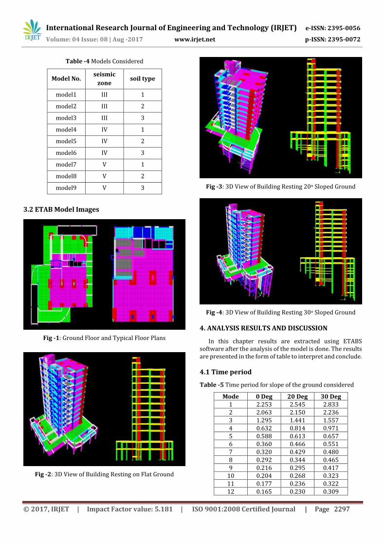
Table -4 Models Considered
Model No. seismic
zone soil type
model1 III 1
model2 III 2
model3 III 3
model4 IV 1
model5 IV 2
model6 IV 3
model7 V 1
model8 V 2
model9 V 3
3.2 ETAB Model Images
Fig -1: Ground Floor and Typical Floor Plans
Fig -2: 3D View of Building Resting on Flat Ground
Fig -3: 3D View of Building Resting 20o Sloped Ground
Fig -4: 3D View of Building Resting 30o Sloped Ground
4. ANALYSIS RESULTS AND DISCUSSION
In this chapter results are extracted using ETABS software after the analysis of the model is done. The results are presented in the form of table to interpret and conclude.
4.1 Time period
Table -5 Time period for slope of the ground considered
Mode 0 Deg 20 Deg 30 Deg 1 2.253 2.545 2.833 2 2.063 2.150 2.236 3 1.295 1.441 1.557 4 0.632 0.814 0.971 5 0.588 0.613 0.657 6 0.360 0.466 0.551 7 0.320 0.429 0.480 8 0.292 0.344 0.465 9 0.216 0.295 0.417
10 0.204 0.268 0.323 11 0.177 0.236 0.322 12 0.165 0.230 0.309

International Research Journal of Engineering and Technology (IRJET) e-ISSN: 2395-0056
Volume: 04 Issue: 08 | Aug -2017 www.irjet.net p-ISSN: 2395-0072
© 2017, IRJET | Impact Factor value: 5.181 | ISO 9001:2008 Certified Journal | Page 2298
Chart -1 Time period for 0o, 20o & 30o sloped ground building
Time period increases with increase in height of the building. From the graph, we can see that time period is maximum for 30o sloped ground building and it is minimum for flat ground building. Time period is maximum for mode 1 and minimum for mode 12.
4.2 Displacement
Table -6 Displacement for slope of the ground considered
ZONES
0
DEG-X
0
DEG-Y
20 DEG-
X
20 DEG-
Y
30 DEG-
X
30 DEG-
Y
Z3-S1 29.9 49.76 25.9
9 45.85
25.27
46.99
Z3-S2 41.29 67.32 35.4
3 62.03
34.33
64
Z3-S3 50.44 83.05 43.5
4 76.33
42.17
78.87
Z4-S1 45.4 74.27 38.9
9 68.83
38.02
70.56
Z4-S2 61.75 101.1
3 52.8
3 93.13 51.5 96.27
Z4-S3 75.61 124.1
8 65.1
6 114.7
7 63.7
5 118.1
2
Z5-S1 68.18 111.8
8 58.4
8 102.7
8 56.8
4 106.1
Z5-S2 92.58 152.1
5 79.7
5 140.2
77.27
144.29
Z5-S3 113.3
2 185.7 98.1
171.64
94.8 176.6
5
Chart -2: Displacement for 0o, 20o & 30o sloped ground building
From the graph, we can see that displacement decreases with increase in slope of the ground. This is due to increase in stiffness of the structure with increase in slope. Also, displacement of the structure depends on stiffness of the soil.
4.3 Storey Shear
Table -7 Storey Shear for slope of the ground considered
ZONES 0 deg 20 deg 30 deg
Z3-S1 3220.84 2800.36 2586.28
Z3-S2 4380.3 3808.41 3517.37
Z3-S3 5378.86 4676.52 4319.25
Z4-S1 4831.26 4200.53 3879.42
Z4-S2 6570.45 5712.61 5276.05
Z4-S3 8068.29 7014.78 6478.87
Z5-S1 7246.89 6300.8 5819.13
Z5-S2 9855.67 8568.92 6899.06
Z5-S3 12102.44 10522.17 8376.55

International Research Journal of Engineering and Technology (IRJET) e-ISSN: 2395-0056
Volume: 04 Issue: 08 | Aug -2017 www.irjet.net p-ISSN: 2395-0072
© 2017, IRJET | Impact Factor value: 5.181 | ISO 9001:2008 Certified Journal | Page 2299
Chart -3: Storey Shear for 0o, 20o & 30o sloped ground building at basement 2
Storey shear is maximum at the base of the building in all the zones. And it is maximum for soil type 3. Here storey shear is maximum for flat ground building.
4.4 Storey Drift Table -8 Storey Drift for slope of the ground considered
ZONES
0 DEG-
X
0 DEG-Y
20 DEG-
X
20 DEG-Y
30 DEG-
X
30 DEG-
Y Z3-S1
0.00077
0.00068
0.00074
0.00077
0.00085
0.00082
Z3-S2
0.00125
0.00104
0.00116
0.00105
0.00122
0.00112
Z3-S3
0.00170
0.00140
0.00158
0.00130
0.00163
0.00138
Z4-S1
0.00115
0.00102
0.00111
0.00115
0.00127
0.00123
Z4-S2
0.00187
0.00156
0.00175
0.00158
0.00184
0.00168
Z4-S3
0.00255
0.00211
0.00238
0.00195
0.00244
0.00206
Z5-S1
0.00172
0.00154
0.00167
0.00173
0.00191
0.00185
Z5-S2
0.00281
0.00234
0.00262
0.00237
0.00275
0.00252
Z5-S3
0.003818
0.003158
0.003562
0.002923
0.00366
0.0030
Chart -4: Storey Drift for 0o, 20o & 30o sloped ground building at storey level 4
Storey drift of the building varies from base to terrace this is due to variation of the loads in the building. With decrease in stiffness of the soil storey drift increases.
5. CONCLUSIONS Following conclusions can be made from the analysis.
1. The natural time period of 30o sloped ground building is high compared to 0o and 20o. This is because of increase in height of the building.
2. Displacement of the building in 20o and 30o sloped ground building is less compared to flat ground building.
3. Displacement is maximum at top floor in all the three zones considered and maximum displacement can be seen in zone V.
4. Displacement is minimum for soil type 1 i.e., for Rock or Hard soil.
5. The storey shear at the base is maximum in all the three zones. It is also maximum for soil type 3. Comparing the values of storey shear in flat ground and sloped ground building it is maximum for flat ground building.
6. From the bar graph for storey drift we can observe that storey drift values varies from basement to terrace, which is due to variation of the loads in the building for every load.
7. Storey drift is maximum for flat ground building compared to 20o and 30o sloped ground building.

International Research Journal of Engineering and Technology (IRJET) e-ISSN: 2395-0056
Volume: 04 Issue: 08 | Aug -2017 www.irjet.net p-ISSN: 2395-0072
© 2017, IRJET | Impact Factor value: 5.181 | ISO 9001:2008 Certified Journal | Page 2300
Storey drift increases with decrease in stiffness of the soil which can be seen in the results obtained for soil type 3 i.e., Soft soil.
8. Form the results and discussion for 0o, 20o and 30o
sloped ground building we can observe that the variation of soil has high impact on building for soil 1. The storey shear, Storey drift and displacement is less when compared to soil 3(loose soil). By this we can conclude that in soil 3 condition building is affected more.
9. Also by observing the graphs we can conclude that for 30o sloped ground building the effect of earthquake is very high when compared to 0o sloped ground building.
ACKNOWLEDGEMENT
I would like to take this opportunity to thank a lot of eminent personalities, without whose constant encouragement, this endeavor of mine would not have become reality.
I would like to express my gratefulness to my guide Ms.
SHILPA B S, Assistant Professor, Department of Civil Engineering, EWIT, Bangalore, for her support and valuable guidance.
I am extremely thankful to Mr. M. S. NAGARAJA GUPTA,
HOD of Civil Engineering Department, EWIT, Bangalore for his encouragement and support.
I would take this opportunity to express my sincere
thanks to Dr. K CHANNAKESHAVALU, Principal of EWIT, Bangalore for his warm support throughout the course.
I would like to thank all the Assistant Professors,
Department of Civil Engineering for providing me with their valuable guidance at all stages of my work.
I would also like to express my Gratitude to Mr. MANJUNATH C BHATTACHARYA, Structural Design Engineer, Nadig consultancy private limited, Bangalore for his valuable guidance and advice.
Last but not the least, I express my deepest sense of
gratitude for the inspiration, enthusiasm and help given by my parents and friends.
REFERENCES
1. S. D. Utterkar and C. R. Nayak, “A Review on Seismic Response of RC Building on Sloping Ground”, International Journal of Engineering Research, Volume No.5 Issue: Special 3, pp: 701-704, February 2016.
2. Sandip Doijad and Surekha Bhalchandra, “Seismic Behavior of RC Buildings Constructed on Plain and Sloping Ground with Different Configuration of
Shear wall”, Journal of Civil Engineering and Environmental Technology, Volume 2, Number 10, pp:59-65, April-June 2015.
3. Paresh G. Mistry and Hemal J. Shah, “Seismic analysis of Building on Sloping Ground Considering Bi-Directional Earthquake”, International Journal of Scientific Development and Research, Volume 1, Issue 4, April 2016.
4. Sujit Kumar, Dr. Vivek Garg and Dr. Abhay Sharma, “Effect of Sloping Ground on Structural Performance of RCC Building Under Seismic Load”, International Journal of Science, Engineering and Technology, Volume 2, Issue 6, August 2014.
5. Sripriya Arjun And Arathi S, “A Study on Dynamic Characteristics of RC Buildings on Hill Slopes”, International Journal of Science and Research, Volume 5, Issue 7, July 2016.
6. B. G. Birajdar and S. S. Nalawade, “Seismic Analysis of Building Resting on Sloping Ground”, 13th World Conference on Earthquake Engineering, Vancouver, B.C., Canada, August 2004.
7. P. Manjunath and Yogeendra R. Holebsgilu, “Seismic Analysis of Multi Storey Building with Flat Slab Resting on Plain and Sloping Ground”, Bonfring International Journal of Man Machine Interface, Volume 4, July 2016.
8. Navyashree K and Sahana T.S, “Use of Flat Slabs in Multi-Storey Commercial Building Situated in High Seismic Zone”, International Journal of Research in Engineering and Technology, Volume 3, Issue 8, August 2014.
9. Likhitharadhya Y R, Praveen J V, Sanjith J and Ranjith A, “Seismic Analysis of Multi-Storey Building Resting on Flat Ground and Sloping Ground”, International Journal of Innovative Research in Science, Engineering and Technology, Volume 5, Issue 6, June 2016.
BIOGRAPHIES
Raghavendra M S, P.G student in Structural Engineering, Department of Civil Engineering, East West Institute of Technology, Bengaluru.
Ms. Shilpa B S, Assistant Professor, Department of Civil Engineering, East West Institute of Technology, Bengaluru.
Mr. Manjunath C Bhattacharya is working as Structural Design Engineer at Nadig consultancy private limited, Bengaluru.