communication protocol - knf.com · usb to rs 232 adaptor! the communication protocol is only...
TRANSCRIPT
Before operating the pump and the accessories, please read the operating instructions on the web site (www.knf.com/downloads) and pay attention to the safety precautions!
LAB Documentation
Communication Protocol
Operating instructions for SIMDOS RC Plus

KNF FLODOS AG Wassermatte 2 6210 Sursee, Schweiz
Tel +41 (0)41 925 00 25 Fax +41 (0)41 925 00 35
www.knf.com
Communication protocol Index
KNF Flodos AG CP_SIMDOS02_EN_04_166851.docx 3 3
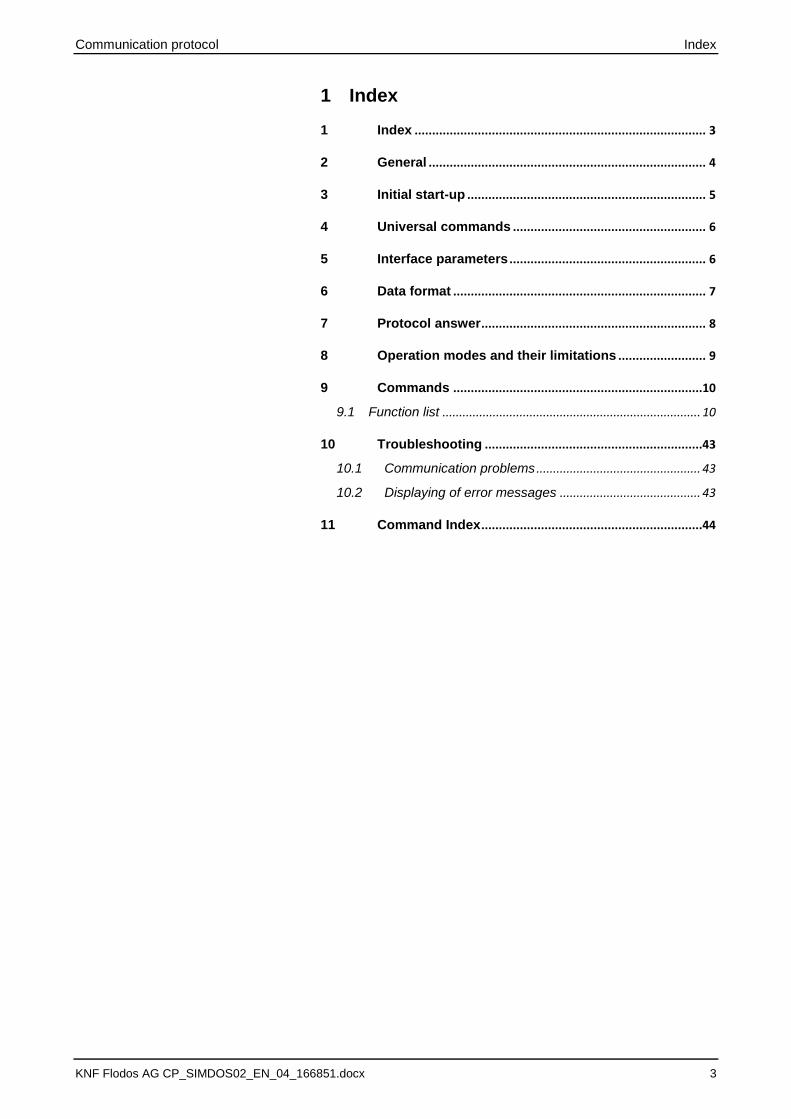
1 Index
1 Index ................................................................................... 3
2 General ............................................................................... 4
3 Initial start-up .................................................................... 5
4 Universal commands ....................................................... 6
5 Interface parameters ........................................................ 6
6 Data format ........................................................................ 7
7 Protocol answer ................................................................ 8
8 Operation modes and their limitations ......................... 9
9 Commands .......................................................................10
9.1 Function list ............................................................................. 10
10 Troubleshooting ..............................................................43
10.1 Communication problems ................................................. 43
10.2 Displaying of error messages .......................................... 43
11 Command Index ...............................................................44

General Communication protocol
4 KNF Flodos AG CP_SIMDOS02_EN_04_166851.docx
2 General
The SIMDOS RC Plus pumps can be controlled by using the standard RS232 serial interface (COM1, COM2, … ). The RS232 serial interface allows one pump to be controlled by a PC based software tool. Any of the commands listed in this document can be carried out as single commands for pump control or verification purpose. This may be of help for customers, who want to develop their own pump control tool.
If your PC does not provide an RS232 serial interface, then use an USB to RS 232 Adaptor!
The communication protocol is only available for the following products:
Name KNF Typ
SIMDOS 10 XX RC Plus FEM1.10 XX.18 RCP
SIMDOS 02 XX RC Plus FEM1.02 XX.18 RCP

Communication protocol Initial start-up
KNF Flodos AG CP_SIMDOS02_EN_04_166851.docx 5 5
3 Initial start-up
WARNING
Danger of automatic start-up
The pump starts up by itself and without warning.
➢ Do not transmit a start command until the system has been tested and is ready for operation
➢ Mark remote-controlled pumps ➢ Before start-up, check that hoses and equipment are
leak-tight and working properly ➢ Do not operate the pump with hazardous media
switch on the pump
Remove protective caps from RC connector plug.
Connect the serial cable (D-Sub cable) to the pump.
Connect serial cable for remote control (D-Sub cable) to a suitable signal source.
Pumpside
Master
D-Sub 9 connector
Fig. 1: KNF Flodos serial cable pin assignment
If your PC is not equipped with an RS 232 Interface, an addi-tional adaptor is needed.
Make sure that the cables are connected
Check connection with:
Name STX Address Cmd str ETX LRC
Example 2 00 ?SI 3 36
Name STX Cmd str ETX LRC
Example 2 3 1 2
If the address has to be changed, make sure, that the mes-sage is send with the right address.
Transmit
Receive:
Universal commands Communication protocol
6 KNF Flodos AG CP_SIMDOS02_EN_04_166851.docx
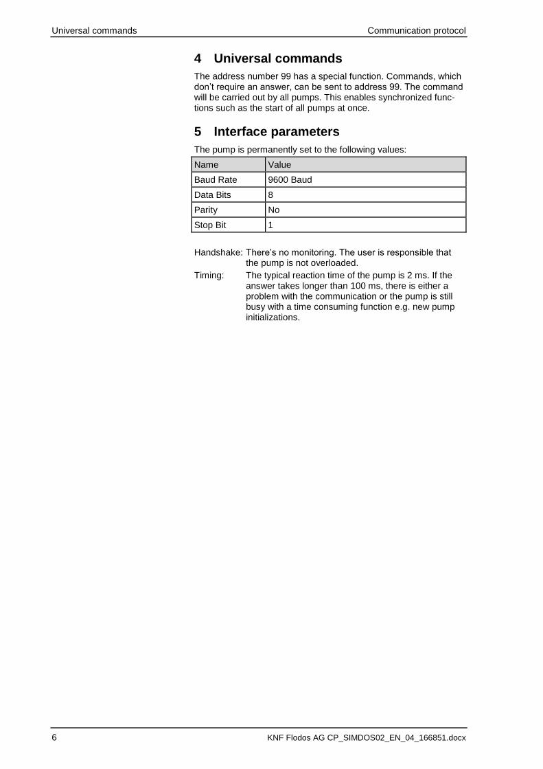
4 Universal commands
The address number 99 has a special function. Commands, which don’t require an answer, can be sent to address 99. The command will be carried out by all pumps. This enables synchronized func-tions such as the start of all pumps at once.
5 Interface parameters
The pump is permanently set to the following values:
Name Value
Baud Rate 9600 Baud
Data Bits 8
Parity No
Stop Bit 1
Handshake: There’s no monitoring. The user is responsible that the pump is not overloaded.
Timing: The typical reaction time of the pump is 2 ms. If the answer takes longer than 100 ms, there is either a problem with the communication or the pump is still busy with a time consuming function e.g. new pump initializations.

Communication protocol Data format
KNF Flodos AG CP_SIMDOS02_EN_04_166851.docx 7 7
6 Data format
Each transmission packet consists of the following bytes:
Name STX Address Cmd str ETX LRC
Size 1 Byte 2 Bytes 3 – 10 Bytes 1 Byte 1 Byte
Example 2 0 0 ? S I 3 36
STX (02h) Start of Text
Address Pump address ‘00’ – ‘99’ ASCII, can be set on the pump
command string (cmd str)
Order of ASCII symbol according to command description
ETX (03h) End of Text
LRC Checksum
Each receiver packet consists of the following bytes:
Name STX Cmd str ETX LRC
Size 1 Byte 1 – 9 Bytes 1 Byte 1 Byte
Example 2 0 0 3 36
STX (02h) Start of Text
Answer All data are in ASCII format
ETX (03h) End of Text
LRC Checksum
The checksum is the last byte in a command string. All bytes (except the checksum (LRC)) are linked by an XOR operation. The receiver of a message compares the received checksum with the calculated checksum from the received data; if the values are identical, the transmission is considered to be error-free.
Instead of a calculated LRC the ASCII Code of the letter ‘U’ (deci-mal 85) can be transmitted. In this case, the pump does not com-pute the checksum of the received data and takes the checksum as valid.
Pseudo code for LRC computation:
LRC = 0
CharacterIndex = 0
Repeat
LRC = LRC xor CommandString[CharacterIndex]
CharakterIndex = CharakterIndex + 1
Until CharakterIndex = LENGTH(CommandString) - 1
….
Compare LRC with the received LRC-byte (first byte after ETX)
….
Where LENGTH() is a function that returns the number of bytes that CommandString contains.
Assuming that the first character in the CommandString array is accessed by index value 0.
Transmit
Receive :
Protocol answer Communication protocol
8 KNF Flodos AG CP_SIMDOS02_EN_04_166851.docx
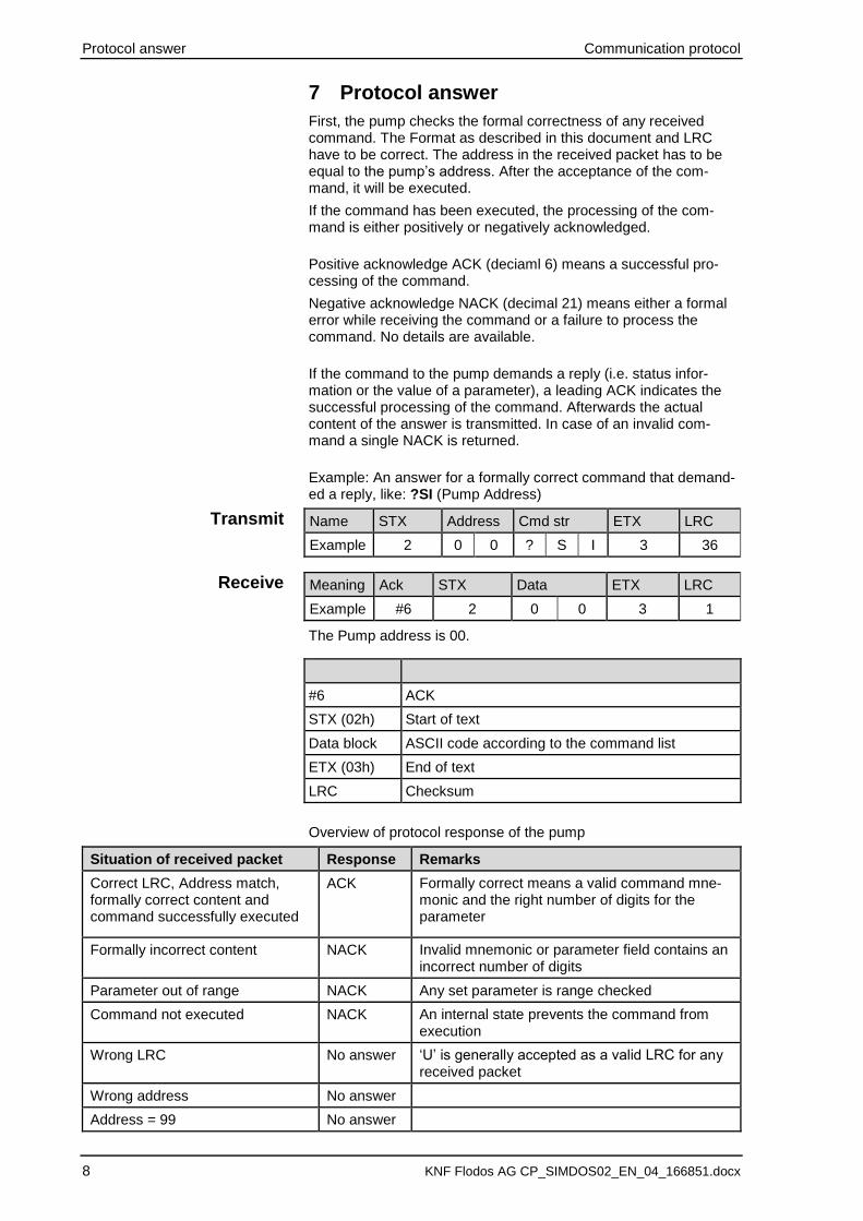
7 Protocol answer
First, the pump checks the formal correctness of any received command. The Format as described in this document and LRC have to be correct. The address in the received packet has to be equal to the pump’s address. After the acceptance of the com-mand, it will be executed.
If the command has been executed, the processing of the com-mand is either positively or negatively acknowledged.
Positive acknowledge ACK (deciaml 6) means a successful pro-cessing of the command.
Negative acknowledge NACK (decimal 21) means either a formal error while receiving the command or a failure to process the command. No details are available.
If the command to the pump demands a reply (i.e. status infor-mation or the value of a parameter), a leading ACK indicates the successful processing of the command. Afterwards the actual content of the answer is transmitted. In case of an invalid com-mand a single NACK is returned.
Example: An answer for a formally correct command that demand-ed a reply, like: ?SI (Pump Address)
Name STX Address Cmd str ETX LRC
Example 2 0 0 ? S I 3 36
Meaning Ack STX Data ETX LRC
Example #6 2 0 0 3 1
The Pump address is 00.
#6 ACK
STX (02h) Start of text
Data block ASCII code according to the command list
ETX (03h) End of text
LRC Checksum
Overview of protocol response of the pump
Situation of received packet Response Remarks
Correct LRC, Address match, formally correct content and command successfully executed
ACK Formally correct means a valid command mne-monic and the right number of digits for the parameter
Formally incorrect content NACK Invalid mnemonic or parameter field contains an incorrect number of digits
Parameter out of range NACK Any set parameter is range checked
Command not executed NACK An internal state prevents the command from execution
Wrong LRC No answer ‘U’ is generally accepted as a valid LRC for any received packet
Wrong address No answer
Address = 99 No answer
Transmit
Receive
Communication protocol Operation modes and their limitations
KNF Flodos AG CP_SIMDOS02_EN_04_166851.docx 9 9
NOTICE
It is not allowed that two pumps can send their answers simulta-neously
The protocol answer can be deactivated (see command SPn).
In this case no ACK or NACK sign is returned. The reply for com-mands that asked for information is always returned.
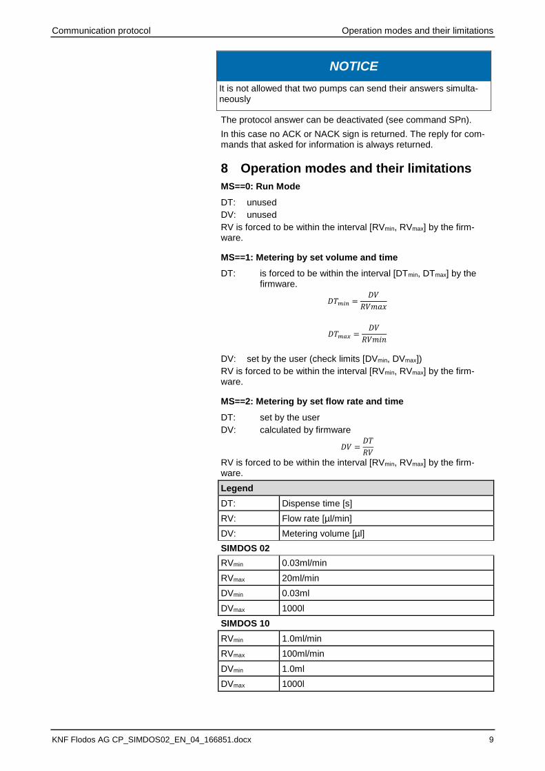
8 Operation modes and their limitations
MS==0: Run Mode
DT: unused
DV: unused
RV is forced to be within the interval [RVmin, RVmax] by the firm-ware. MS==1: Metering by set volume and time
DT: is forced to be within the interval [DTmin, DTmax] by the firmware.
𝐷𝑇𝑚𝑖𝑛 =𝐷𝑉
𝑅𝑉𝑚𝑎𝑥
𝐷𝑇𝑚𝑎𝑥 =𝐷𝑉
𝑅𝑉𝑚𝑖𝑛
DV: set by the user (check limits [DVmin, DVmax])
RV is forced to be within the interval [RVmin, RVmax] by the firm-ware. MS==2: Metering by set flow rate and time
DT: set by the user
DV: calculated by firmware
𝐷𝑉 =𝐷𝑇
𝑅𝑉
RV is forced to be within the interval [RVmin, RVmax] by the firm-ware.
Legend
DT: Dispense time [s]
RV: Flow rate [µl/min]
DV: Metering volume [µl]
SIMDOS 02
RVmin 0.03ml/min
RVmax 20ml/min
DVmin 0.03ml
DVmax 1000l
SIMDOS 10
RVmin 1.0ml/min
RVmax 100ml/min
DVmin 1.0ml
DVmax 1000l
Commands Communication protocol
10 KNF Flodos AG CP_SIMDOS02_EN_04_166851.docx
9 Commands
9.1 Function list
9.1.1 Mode select: Run-mode / Dispense-mode .................. 11
9.1.2 Start, Stop, Prime/Drain ................................................. 12
9.1.3 Run mode flow rate µl/min. ............................................ 13
9.1.4 Dispense mode dispense volume l ............................ 15
9.1.5 Dispense mode time for dispensing a volume .......... 16
9.1.6 Dispense mode: number of volumes ........................... 18
9.1.7 Dispense mode: Break time between volumes.......... 19
9.1.8 Actual run or dispense time counter. .......................... 20
9.1.9 Actual run or dispense volume counter µl ................. 21
9.1.10 Analog control signal type selection ........................... 22
9.1.11 Analog Range Selection ................................................ 23
9.1.12 Digital input 1 function ................................................... 24
9.1.13 Digital input 2 function ................................................... 25
9.1.14 Open collector output function .................................... 27
9.1.15 Language select .............................................................. 28
9.1.16 Customer level measured calibration volume ........... 29
9.1.17 Customer level calibration factor % ............................ 30
9.1.18 Characteristic pump profile selection ......................... 31
9.1.19 LCD display contrast ...................................................... 32
9.1.20 Auto-start after power on ............................................... 33
9.1.21 Pump model and firmware version .............................. 34
9.1.22 Communication check function ................................... 35
9.1.23 Protocol answer setting ................................................. 36
9.1.24 Initialize the pump (new start) ....................................... 37
9.1.25 Pump reset to factory settings ..................................... 38
9.1.26 Pump status request ...................................................... 39
9.1.27 Pump address nn ............................................................ 41
9.1.28 Maintenance position ..................................................... 42
Communication protocol Commands
KNF Flodos AG CP_SIMDOS02_EN_04_166851.docx 11 11
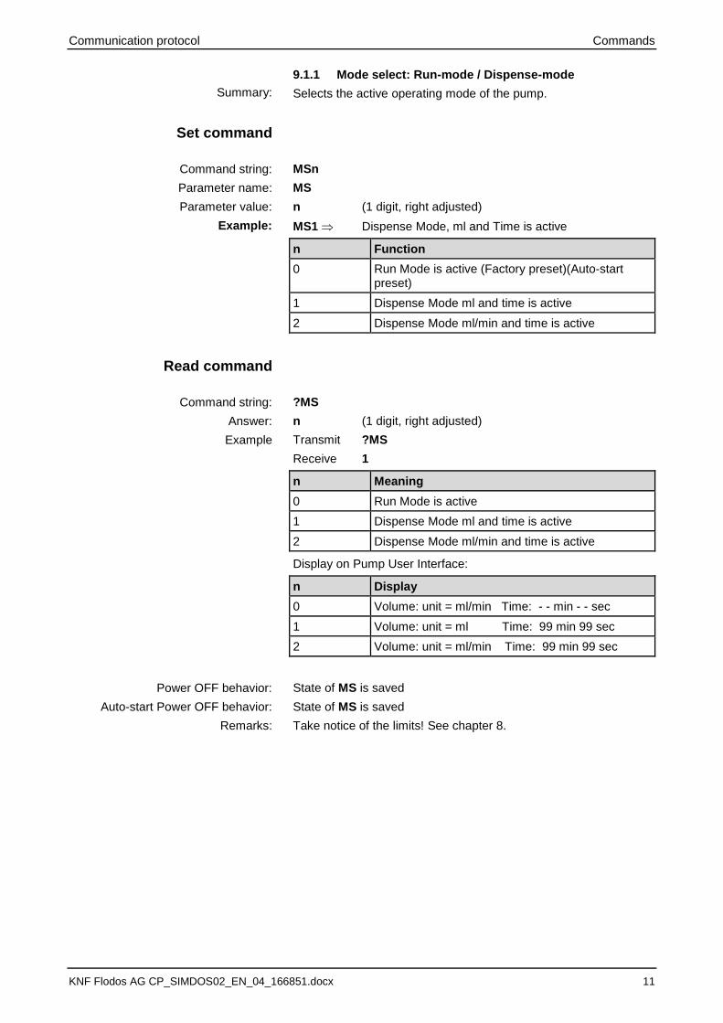
9.1.1 Mode select: Run-mode / Dispense-mode
Selects the active operating mode of the pump.
MSn
MS
n (1 digit, right adjusted)
MS1 Dispense Mode, ml and Time is active
n Function
0 Run Mode is active (Factory preset)(Auto-start preset)
1 Dispense Mode ml and time is active
2 Dispense Mode ml/min and time is active
?MS
n (1 digit, right adjusted)
Transmit ?MS
Receive 1
n Meaning
0 Run Mode is active
1 Dispense Mode ml and time is active
2 Dispense Mode ml/min and time is active
Display on Pump User Interface:
n Display
0 Volume: unit = ml/min Time: - - min - - sec
1 Volume: unit = ml Time: 99 min 99 sec
2 Volume: unit = ml/min Time: 99 min 99 sec
State of MS is saved
State of MS is saved
Take notice of the limits! See chapter 8.
Summary:
Set command
Command string:
Parameter name:
Parameter value:
Example:
Read command
Command string:
Answer:
Example
Power OFF behavior:
Auto-start Power OFF behavior:
Remarks:

Commands Communication protocol
12 KNF Flodos AG CP_SIMDOS02_EN_04_166851.docx
9.1.2 Start, Stop, Prime/Drain
To initiate primary pump function. Start pumping, stop pumping, start Prime/Drain cycle.
KY
n (1 digit, right adjusted)
KYn
KY2 Priming the pump
n Function
0 Stop (Factory preset)
1 Start (Auto-start preset)
2 Prime/Drain (1 stroke)
3 Pause
No parameter read function
Display on Pump User Interface:
n Display
0 Volume counter stops and the STOP indicator is active
1 Volume counter either resets to 0 or keeps its value and starts counting corresponding to the previous state of pump (either 0 (STOP) or 3 (PAUSE))
2 Volume counter resets to 0 and finally displays the dispensed volume of the prime stroke
3 Volume counter xxx stops, is blinking and the PAUSE indicator is active
State of KY reset to factory preset (Always Stop when power ON).
State of KY reset to factory preset (Always Stop when power ON).
See AS (Section 9.1.20) for more information on autostart
Summary:
Set command
Parameter name:
Parameter value:
Command string:
Example:
Read Command: Command string:
Power OFF behavior:
Auto-start Power OFF behavior:
Remarks:

Communication protocol Commands
KNF Flodos AG CP_SIMDOS02_EN_04_166851.docx 13 13
9.1.3 Run mode flow rate µl/min.
Sets the set value for the flow rate in Run mode. The unit is µl/min.
RVnnnnnnnn
RV
nnnnnnnn (8 digits, right adjusted)
RV00020000 20’000 µl/min
SIMDOS10
nnnnnnnn Function
0...99’999’999 Set value for the flow rate [µl/min] in Run mode
00’100’000 FEM 1.10 Maximum accepted value (NACK if higher)
00’001’000 FEM 1.10 Minimum accepted value (NACK if lower)
00’010’000 Factory preset
SIMDOS02
nnnnnnnn Function
0...99’999’999 Set value for the flow rate [µl/min] in Run mode
00'020'000 FEM 1.02 .18 Maximum accepted value (NACK if higher)
00'000'030 FEM 1.02 .18 Minimum accepted value (NACK if lower)
00’10’000 Factory preset
?RV
nnnnnnnn (8 digits, right adjusted)
Transmit ?RV
Receive 00020000
nnnnnnnn Meaning
0…99999999 Current set value for flow rate in µl/min
Summary:
Set command
Command String
Command name:
Parameter value:
Example:
Read Command
Command String
Answer:
Example:
Commands Communication protocol
14 KNF Flodos AG CP_SIMDOS02_EN_04_166851.docx
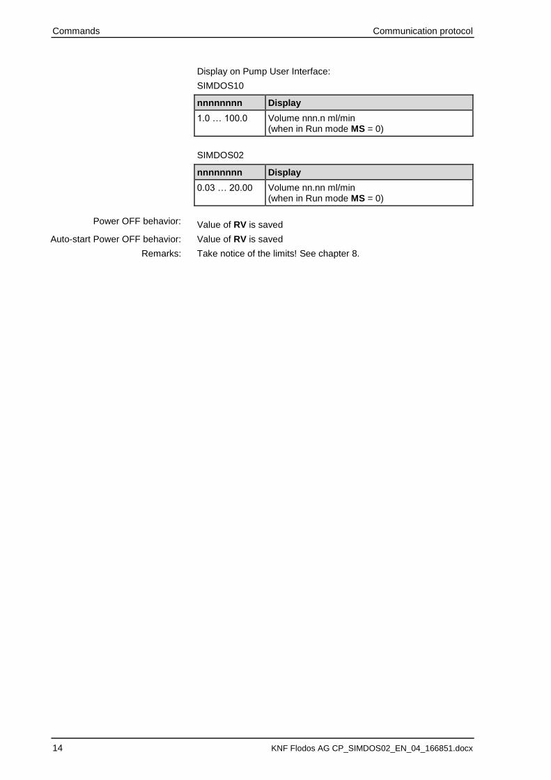
Display on Pump User Interface:
SIMDOS10
nnnnnnnn Display
1.0 … 100.0 Volume nnn.n ml/min (when in Run mode MS = 0)
SIMDOS02
nnnnnnnn Display
0.03 … 20.00 Volume nn.nn ml/min (when in Run mode MS = 0)
Value of RV is saved
Value of RV is saved
Take notice of the limits! See chapter 8.
Power OFF behavior:
Auto-start Power OFF behavior:
Remarks:

Communication protocol Commands
KNF Flodos AG CP_SIMDOS02_EN_04_166851.docx 15 15
9.1.4 Dispense mode dispense volume l
Sets the set value for the dispense volume in Dispense-mode. The unit is µl.
DVnnnnnnnn
DV
nnnnnnnn (8 digits, right adjusted)
DV00020000 20’000 µl
SIMDOS10
nnnnnnnn Function
0...99’999’999 Set value for the dispense volume in Dispense mode [µl]
00’999’999 Maximum accepted value (NACK if higher)
00’001’000 Minimum accepted value (NACK if lower)
00’010’000 Factory preset, Auto-start preset
SIMDOS02
nnnnnnnn Function
0...99’999’999 Set value for the dispense volume in Dispense mode
00’999’999 Maximum accepted value (NACK if higher)
00'000'030 Minimum accepted value (NACK if lower)
00’10’000 Factory preset, Auto-start preset
?DV
nnnnnnnn (8 digits, right adjusted)
Transmit ?DV
Receive 00020000 20’000 µl
nnnnnnnn Meaning
min…99999999 Current set value for dispense volume in µl
Display on Pump User Interface:
nnnnnnnn Massage
min … 999.9 Volume nnn.n ml (when in Dispense mode MS = 1)
Value of DV is saved
Value of DV is saved
Take notice of the limits! See chapter 8.
Summary:
Set command
Command string
Command name:
Parameter value:
Example:
Read command
Command string:
Answer:
Example
Power OFF behavior:
Auto-start Power OFF behavior:
Remarks:

Commands Communication protocol
16 KNF Flodos AG CP_SIMDOS02_EN_04_166851.docx
9.1.5 Dispense mode time for dispensing a volume
Sets the set value for the time to dispense a volume in Dispense mode.
DThhmmssss
DT
hhmmssss (8 digits, [hh:mm:ss.ss] “h”: hour, “m”: minute, “s”:seconds, “.ss”: 1/100 seconds)
DT00010000 1 min
hhmmssss Function
99‘99’99’99 Set value for the time to dispense a volume in Dispense mode
99’59’59’99 Maximum accepted value (NACK if higher)
00’00’01’00 Minimum accepted value (NACK if lower)
00’00’10’00 Factory preset, Auto-start preset (10 seconds)
?DT
hhmmssss (8 digits, right adjusted)
Transmit ?DT
Receive 00010000 1 min
hhmmssss Meaning
0…99999999 “h”: hour, “m”: minute, “s”:seconds, “.ss”: 1/100 seconds
Display on Pump User Interface:
nn:nn Display
mm:ss 00:01 - 59:59 Time: mm [min.] ss [sec.] (when in Dispense mode MS = 1 or 2)
hh:mm 01:00 - 99:59 Time: hh [h.] mm [min.] (when in Dispense mode MS = 1 or 2)
off --:-- Time: - - min - - sec (when in Run mode MS = 0)
User Interface behavior:
• If time is dialed from “0” to a time value, then: MS = 1 or 2, DV = RV
• If time is dialed to “0”, then: MS = 0, RV = DV, display time “off”
Value of DT is saved
Value of DT is saved
Summary:
Set command
Command string:
Parameter name:
Parameter value:
Example:
Read command
Command string:
Answer:
Example:
Power OFF behavior:
Auto-start Power OFF behavior:

Communication protocol Commands
KNF Flodos AG CP_SIMDOS02_EN_04_166851.docx 17 17
Take notice of the limits! See chapter 8.
NOTICE
The pump will only accept this dispense time, as long as it is between the pump internal min. and max. time for dispensing a selected basic dispense volume, otherwise the pump will set the internal min. or max. time. A simple read back helps to check the actual dispense time. Time resolution is 1.00s.
Remarks:

Commands Communication protocol
18 KNF Flodos AG CP_SIMDOS02_EN_04_166851.docx
9.1.6 Dispense mode: number of volumes
The number of cycles, that the given volume shall be dispensed, is defined
DNnnnnn
DN
nnnnn (5 digits, right adjusted)
DN00050 50 cycles
nnnnn Function
0 Function off
1 Cyclic dispensing is deactivated
2...999 nnnnn represents the number of dispensed volumes
1000 Infinite number of repetitions
?DN
nnnnn (5 digits, right adjusted)
Transmit ?DN
Receive 00050 50 cycles
nnnnn Meaning
0 Function off
1 Cyclic dispensing is deactivated
2...999 Currently configured number of dispense volumes
1000 Dispense volume is infinitely repeated
Display on Pump User Interface:
nnnnn Display
0 Function off
1 Cyclic dispensing is deactivated (no indication)
2...999 Counter of dispensed volumes / Number of volumes
1000 The text string "INF"
Value of DN is saved
Value of DN is saved
1/100 s are rounded to seconds as this is the minimum resolution of time.
Summary:
Set command
Command string:
Command name:
Parameter value:
Example
Read command
Command string:
Answer:
Example:
Power OFF behavior:
Auto-start Power OFF behavior:
Remarks:

Communication protocol Commands
KNF Flodos AG CP_SIMDOS02_EN_04_166851.docx 19 19
9.1.7 Dispense mode: Break time between volumes
Break time between two programmed dispense cycles
DBnnnnn
DB
nnnnn (5 digits, right adjusted)
DB00010 10 seconds break time
nnnnn Function
1...5999 Break time in seconds
?DB
nnnnn (5 digits, right adjusted)
Transmit ?DB
Receive 00010 10 seconds break time
nnnnn Meaning
1...5999 Break time in seconds
Display on Pump User Interface:
nnnnn Display
1...5999 Break time in seconds, is counting backwards when active
Value of DB is saved
Value of DB is saved
--
Summary:
Set command
Command string:
Parameter name:
Parameter value:
Example:
Read Command
Command string:
Answer:
Example:
Power OFF behavior:
Auto-start Power OFF behavior:
Remarks:

Commands Communication protocol
20 KNF Flodos AG CP_SIMDOS02_EN_04_166851.docx
9.1.8 Actual run or dispense time counter.
Time counter of the Dispense mode (and Run mode). Counter resets to 0 and starts at dispense start or run start
No command string
--
--
--
?TT
hhmmssss 5 digits, right adjusted [hh:mm:ss.ss] “h”: hour, “m”: minute, “s”:seconds, “.ss”: 1/100 seconds
Transmit ?TT
Receive 00010000 1 minute
hhmmssss Meaning
0…99999999 “h”: hour, “m”: minute, “s”:seconds, “.ss”: 1/100 seconds
00000000 Dispense is not started / Run is not started
Display on Pump User Interface:
No Display
Value of TT is not saved
Value of TT is not saved
--
Summary:
Set command
Command string:
Parameter name:
Parameter value:
Example:
Read command
Command string:
Answer:
Example:
Power OFF behavior:
Auto-start Power OFF behavior:
Remarks:

Communication protocol Commands
KNF Flodos AG CP_SIMDOS02_EN_04_166851.docx 21 21
9.1.9 Actual run or dispense volume counter µl
Volume counter of the Dispense mode (and Run mode). Counter resets to 0 and starts at dispense start or run start
No command string
--
--
--
?TV
nnnnnnnnn (9 digits, right adjusted)
Transmit ?TV
Receive 000010000 10 ml
nnnnnnnnn Meaning
0…999‘999‘999 Dispensed volume in l
Display on Pump User Interface:
n Display
0…999999.9 Dispensed volume since last pump start in ml
> 999999 If Upper limit of TV is reached the counter stops
Value of TV is not saved
Value of TV is not saved
Since the pump only dispenses during pressure strokes, the dis-pense counter needs calibration. The counter is based on the calibrated pump stroke volume which is summed up by incremental steps.
Take note of the upper limit. If the dispensed volume is larger than the upper limit of TV, the volume counter displays the difference to 1000 l and the display shows “> 1000 l”
Summary:
Set command
Command string:
Parameter name:
Parameter value:
Example:
Read command
Command string:
Answer:
Example:
Power OFF behavior:
Auto-start Power OFF behavior:
Remarks:
Commands Communication protocol
22 KNF Flodos AG CP_SIMDOS02_EN_04_166851.docx
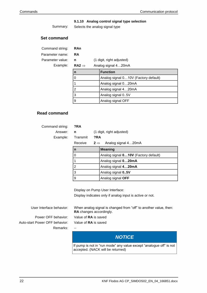
9.1.10 Analog control signal type selection
Selects the analog signal type
RAn
RA
n (1 digit, right adjusted)
RA2 Analog signal 4…20mA
n Function
0 Analog signal 0…10V (Factory default)
1 Analog signal 0…20mA
2 Analog signal 4…20mA
3 Analog signal 0..5V
9 Analog signal OFF
?RA
n (1 digit, right adjusted)
Transmit ?RA
Receive 2 Analog signal 4…20mA
n Meaning
0 Analog signal 0…10V (Factory default)
1 Analog signal 0…20mA
2 Analog signal 4…20mA
3 Analog signal 0..5V
9 Analog signal OFF
Display on Pump User Interface:
Display indicates only if analog input is active or not.
When analog signal is changed from “off” to another value, then: RA changes accordingly.
Value of RA is saved
Value of RA is saved
--
NOTICE
If pump is not in “run mode” any value except “analogue off” is not accepted. (NACK will be returned)
Summary:
Set command
Command string:
Parameter name:
Parameter value:
Example:
Read command
Command string:
Answer:
Example:
User Interface behavior:
Power OFF behavior:
Auto-start Power OFF behavior:
Remarks:
Communication protocol Commands
KNF Flodos AG CP_SIMDOS02_EN_04_166851.docx 23 23
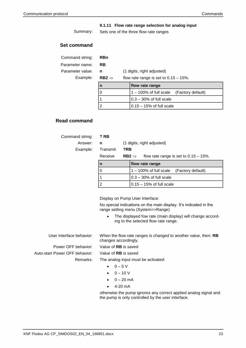
9.1.11 Flow rate range selection for analog input
Sets one of the three flow rate ranges
RBn
RB
n (1 digits, right adjusted)
RB2 flow rate range is set to 0.15 – 15%.
n flow rate range
0 1 – 100% of full scale (Factory default)
1 0.3 – 30% of full scale
2 0.15 – 15% of full scale
? RB
n (1 digits, right adjusted)
Transmit ?RB
Receive RB2 flow rate range is set to 0.15 – 15%.
n flow rate range
0 1 – 100% of full scale (Factory default)
1 0.3 – 30% of full scale
2 0.15 – 15% of full scale
Display on Pump User Interface:
No special indications on the main display. It’s indicated in the range setting menu (System=>Range)
• The displayed fow rate (main display) will change accord-ing to the selected flow rate range.
When the flow rate ranges is changed to another value, then: RB changes accordingly.
Value of RB is saved
Value of RB is saved
The analog input must be activated:
• 0 – 5 V
• 0 – 10 V
• 0 – 20 mA
• 4-20 mA
otherwise the pump ignores any correct applied analog signal and the pump is only controlled by the user interface.
Summary:
Set command
Command string:
Parameter name:
Parameter value:
Example:
Read command
Command string:
Answer:
Example:
User Interface behavior:
Power OFF behavior:
Auto-start Power OFF behavior:
Remarks:
Commands Communication protocol
24 KNF Flodos AG CP_SIMDOS02_EN_04_166851.docx
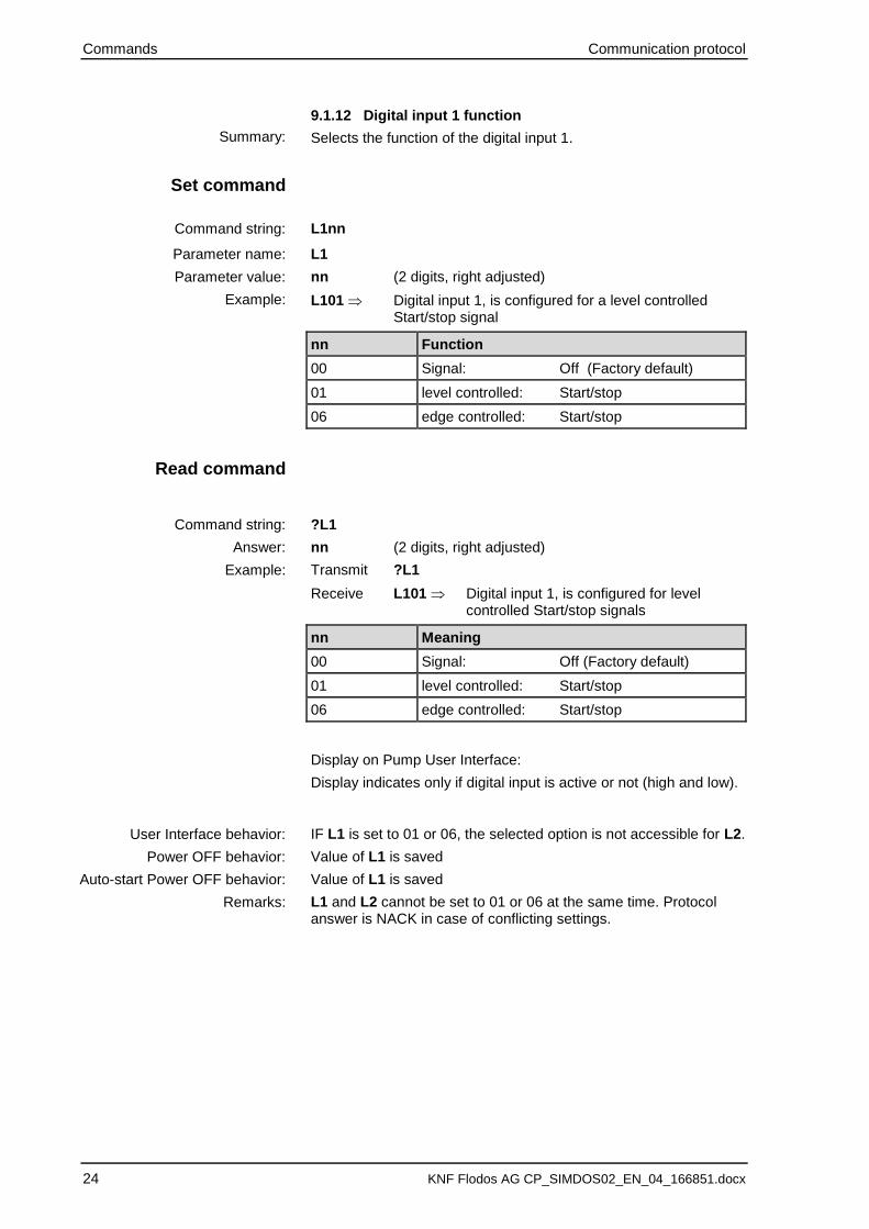
9.1.12 Digital input 1 function
Selects the function of the digital input 1.
L1nn
L1
nn (2 digits, right adjusted)
L101 Digital input 1, is configured for a level controlled Start/stop signal
nn Function
00 Signal: Off (Factory default)
01 level controlled: Start/stop
06 edge controlled: Start/stop
?L1
nn (2 digits, right adjusted)
Transmit ?L1
Receive L101 Digital input 1, is configured for level controlled Start/stop signals
nn Meaning
00 Signal: Off (Factory default)
01 level controlled: Start/stop
06 edge controlled: Start/stop
Display on Pump User Interface:
Display indicates only if digital input is active or not (high and low).
IF L1 is set to 01 or 06, the selected option is not accessible for L2.
Value of L1 is saved
Value of L1 is saved
L1 and L2 cannot be set to 01 or 06 at the same time. Protocol answer is NACK in case of conflicting settings.
Summary:
Set command
Command string:
Parameter name:
Parameter value:
Example:
Read command
Command string:
Answer:
Example:
User Interface behavior:
Power OFF behavior:
Auto-start Power OFF behavior:
Remarks:

Communication protocol Commands
KNF Flodos AG CP_SIMDOS02_EN_04_166851.docx 25 25
9.1.13 Digital input 2 function
Selects the function of the digital input 2.
L2nn
L2
nn (2 digits, right adjusted)
L201 Digital input 2, is configured for level controlled Start/stop signals
nn Function
00 Signal 2: Off (Factory default)
01 level controlled: Start/stop signal
06 edge controlled: Start/stop signal
08 Pump Error reset & Pump Stop on signal edge.
09 Prime/Drain on signal level and error reset on signal edge
10 Error reset on signal edge and Prime/Drain after 1 second on signal level
Summary:
Set command
Command string:
Parameter name:
Parameter value:
Example:
Logic level
active [1]
not active [0]
Error reset t
L2 = 08
active [1]
not active [0]
Error reset t
L2 = 09
Prime/Drain
active [1]
not active [0]
Error reset t
L2 = 10 Prime/Drain
1s
Commands Communication protocol
26 KNF Flodos AG CP_SIMDOS02_EN_04_166851.docx
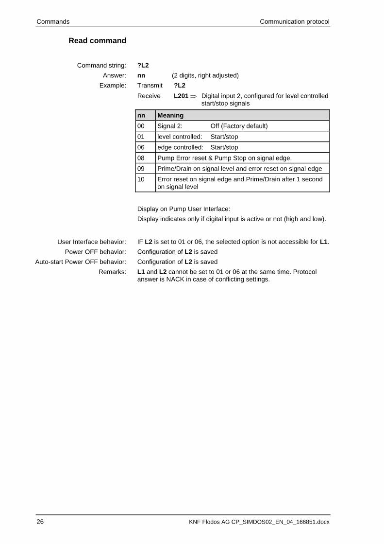
?L2
nn (2 digits, right adjusted)
Transmit ?L2
Receive L201 Digital input 2, configured for level controlled start/stop signals
nn Meaning
00 Signal 2: Off (Factory default)
01 level controlled: Start/stop
06 edge controlled: Start/stop
08 Pump Error reset & Pump Stop on signal edge.
09 Prime/Drain on signal level and error reset on signal edge
10 Error reset on signal edge and Prime/Drain after 1 second on signal level
Display on Pump User Interface:
Display indicates only if digital input is active or not (high and low).
IF L2 is set to 01 or 06, the selected option is not accessible for L1.
Configuration of L2 is saved
Configuration of L2 is saved
L1 and L2 cannot be set to 01 or 06 at the same time. Protocol answer is NACK in case of conflicting settings.
Read command
Command string:
Answer:
Example:
User Interface behavior:
Power OFF behavior:
Auto-start Power OFF behavior:
Remarks:
Communication protocol Commands
KNF Flodos AG CP_SIMDOS02_EN_04_166851.docx 27 27
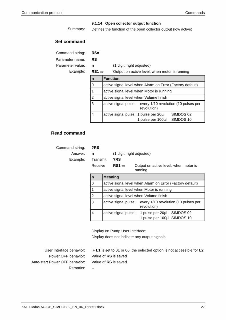
9.1.14 Open collector output function
Defines the function of the open collector output (low active)
RSn
RS
n (1 digit, right adjusted)
RS1 Output on active level, when motor is running
n Function
0 active signal level when Alarm on Error (Factory default)
1 active signal level when Motor is running
2 active signal level when Volume finish
3 active signal pulse: every 1/10 revolution (10 pulses per revolution)
4 active signal pulse: 1 pulse per 20µl SIMDOS 02
1 pulse per 100µl SIMDOS 10
?RS
n (1 digit, right adjusted)
Transmit ?RS
Receive RS1 Output on active level, when motor is running
n Meaning
0 active signal level when Alarm on Error (Factory default)
1 active signal level when Motor is running
2 active signal level when Volume finish
3 active signal pulse: every 1/10 revolution (10 pulses per revolution)
4 active signal pulse: 1 pulse per 20µl SIMDOS 02
1 pulse per 100µl SIMDOS 10
Display on Pump User Interface:
Display does not indicate any output signals.
IF L1 is set to 01 or 06, the selected option is not accessible for L2.
Value of RS is saved
Value of RS is saved
--
Summary:
Set command
Command string:
Parameter name:
Parameter value:
Example:
Read command
Command string:
Answer:
Example:
User Interface behavior:
Power OFF behavior:
Auto-start Power OFF behavior:
Remarks:

Commands Communication protocol
28 KNF Flodos AG CP_SIMDOS02_EN_04_166851.docx
9.1.15 Language select
Selects the language of the user interface
LSn
LS
n (1 digit, right adjusted)
LS1 German
n Function
0 English
1 German
2 French
3 Spanish
4 Italian
5 Chinese
6 Japanese
?LS
n (1 digit, right adjusted)
Transmit ?LS
Receive LS1 German
n Meaning
0…6 User interface language according to parameter value
Display on Pump User Interface:
n Display
0…6 User interface language according to parameter value
Value of LS is saved
Value of LS is saved
--
Summary:
Set command
Command string:
Parameter name:
Parameter value:
Example:
Read command
Command string:
Answer:
Example:
Power OFF behavior:
Auto-start Power OFF behavior:
Remarks:

Communication protocol Commands
KNF Flodos AG CP_SIMDOS02_EN_04_166851.docx 29 29
9.1.16 Customer level measured calibration volume
Customer level calibration based on Run mode flow rate or Dis-pense mode volume
CFnnnnnnnn
CF
nnnnnnnn (8 digits, right adjusted)
CF 00000100 100 µl or 100 µl/min, it depends on the mode of operation
n Function
0...99999999 Customer measured flow rate [µl/min] or dispense volume in [µl]
No parameter read function
-
-
Display on Pump User Interface:
n Display
0…9999 Measured value nnnn in ml (when in Dispense mode MS=1)
0…9999 Measured value nnnn in ml/min (when in Run mode MS=0)
Value of CF is not saved
Value of CFis not saved
The parameter CF is a user input value only.
Setting CF initiates the computation of the calibration parameter CH. See definition of CH.
NOTICE
CH is computed based on CF (see section 9.1.17).
If the value of CF violates - after computation - the range of CH, CF is not accepted and a NACK sign is returned.
Summary:
Set command
Command string:
Parameter name:
Parameter value:
Example:
Read command
Command string:
Answer:
Example:
Power OFF behavior:
Auto-start Power OFF behavior:
Remarks:
Commands Communication protocol
30 KNF Flodos AG CP_SIMDOS02_EN_04_166851.docx
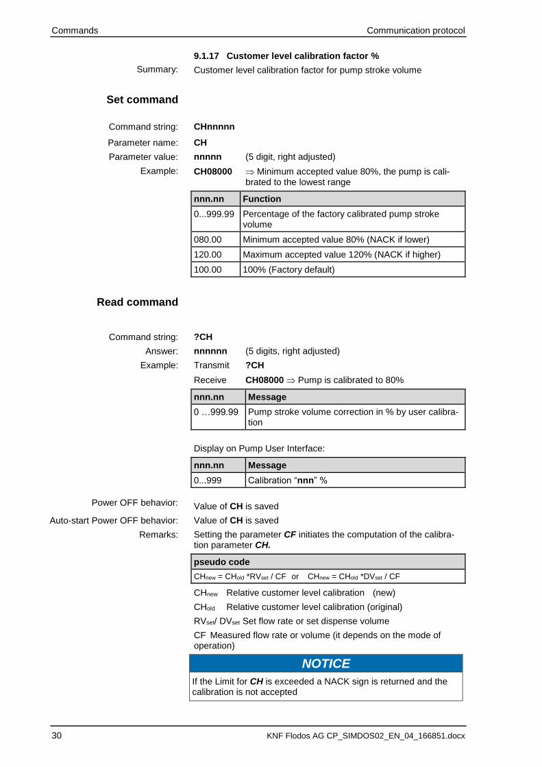
9.1.17 Customer level calibration factor %
Customer level calibration factor for pump stroke volume
CHnnnnn
CH
nnnnn (5 digit, right adjusted)
CH08000 Minimum accepted value 80%, the pump is cali-brated to the lowest range
nnn.nn Function
0...999.99 Percentage of the factory calibrated pump stroke volume
080.00 Minimum accepted value 80% (NACK if lower)
120.00 Maximum accepted value 120% (NACK if higher)
100.00 100% (Factory default)
?CH
nnnnnn (5 digits, right adjusted)
Transmit ?CH
Receive CH08000 Pump is calibrated to 80%
nnn.nn Message
0 …999.99 Pump stroke volume correction in % by user calibra-tion
Display on Pump User Interface:
nnn.nn Message
0...999 Calibration “nnn” %
Value of CH is saved
Value of CH is saved
Setting the parameter CF initiates the computation of the calibra-tion parameter CH.
pseudo code
CHnew = CHold *RVset / CF or CHnew = CHold *DVset / CF
CHnew Relative customer level calibration (new)
CHold Relative customer level calibration (original)
RVset/ DVset Set flow rate or set dispense volume
CF Measured flow rate or volume (it depends on the mode of operation)
NOTICE
If the Limit for CH is exceeded a NACK sign is returned and the calibration is not accepted
Summary:
Set command
Command string:
Parameter name:
Parameter value:
Example:
Read command
Command string:
Answer:
Example:
Power OFF behavior:
Auto-start Power OFF behavior:
Remarks:
Communication protocol Commands
KNF Flodos AG CP_SIMDOS02_EN_04_166851.docx 31 31
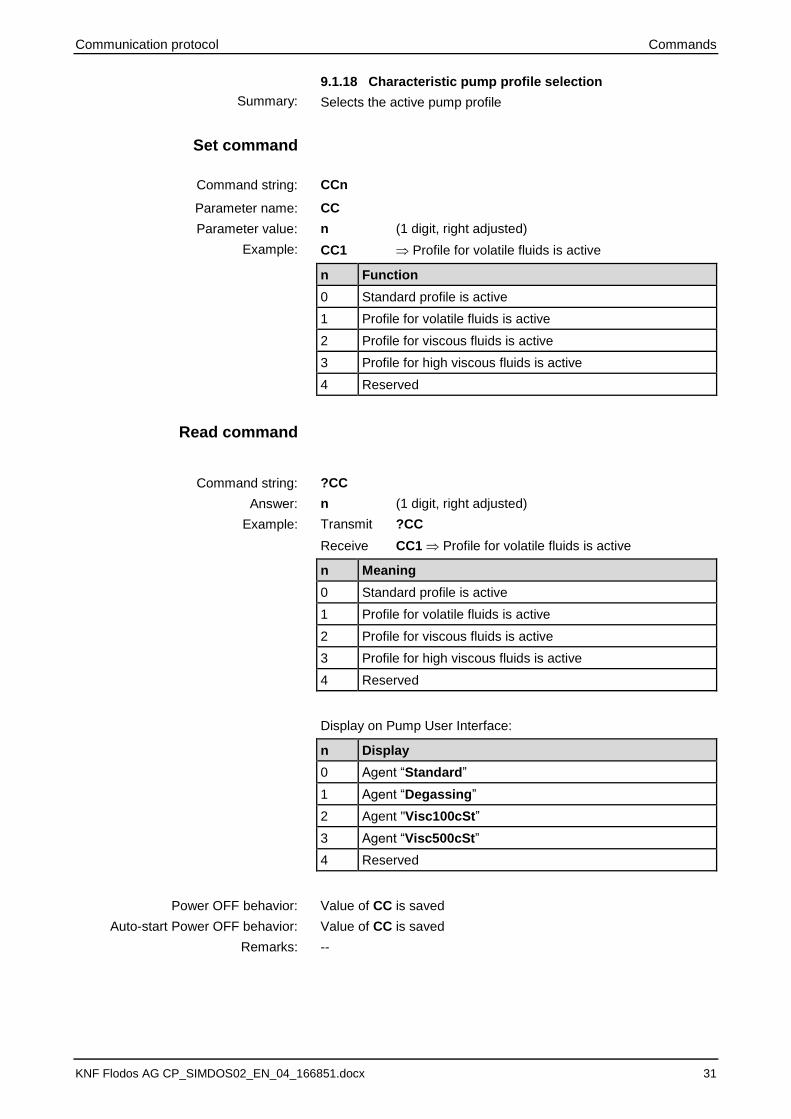
9.1.18 Characteristic pump profile selection
Selects the active pump profile
CCn
CC
n (1 digit, right adjusted)
CC1 Profile for volatile fluids is active
n Function
0 Standard profile is active
1 Profile for volatile fluids is active
2 Profile for viscous fluids is active
3 Profile for high viscous fluids is active
4 Reserved
?CC
n (1 digit, right adjusted)
Transmit ?CC
Receive CC1 Profile for volatile fluids is active
n Meaning
0 Standard profile is active
1 Profile for volatile fluids is active
2 Profile for viscous fluids is active
3 Profile for high viscous fluids is active
4 Reserved
Display on Pump User Interface:
n Display
0 Agent “Standard”
1 Agent “Degassing”
2 Agent "Visc100cSt”
3 Agent “Visc500cSt”
4 Reserved
Value of CC is saved
Value of CC is saved
--
Summary:
Set command
Command string:
Parameter name:
Parameter value:
Example:
Read command
Command string:
Answer:
Example:
Power OFF behavior:
Auto-start Power OFF behavior:
Remarks:

Commands Communication protocol
32 KNF Flodos AG CP_SIMDOS02_EN_04_166851.docx
9.1.19 LCD display contrast
Sets the contrast level of the LCD display.
LCnnn
LC
nnn (3 digits, right adjusted)
LC060 LCD Contrast 60%
n Function
000 ... 100 LCD display contrast setting
100 Maximum accepted value (NACK if higher)
000 Minimum accepted value (NACK if lower)
040 (Factory default)
?LC
nnn (3 digits, right adjusted)
Transmit ?LC
Receive LC040 LCD Contrast 40% (default setting)
nnn Meaning
000…100 LCD display contrast setting
Display on Pump User Interface:
nnn Display
000…100 Contrast “nnn”
Value of LC is saved
Value of LC is saved
Take notice of the limits!
Summary:
Set command
Command string:
Parameter name:
Parameter value:
Example:
Read command
Command string:
Answer:
Example:
Power OFF behavior:
Auto-start Power OFF behavior:
Remarks:

Communication protocol Commands
KNF Flodos AG CP_SIMDOS02_EN_04_166851.docx 33 33
9.1.20 Auto-start after power on
Settings of automatic start after power off/switch off.
With active Auto-start the pump will start automatically if one of the following actions takes place:
• The power plug is attached to the pump
• The pump is switched on
NOTICE
If any input control signal is configured the pump will stay in pause state until a start trigger is given.
SAn
SA
n (1 digit, right adjusted)
SA1 activate Auto-start
n Function
0 Auto-start inactive (Factory default)
1 Auto-start active
?SA
n (1 digit, right adjusted)
Transmit ?SA
Receive SA1 Auto-start is active
n Meaning
0 Auto-start is inactive
1 Auto-start is active
Display on Pump User Interface:
n Display
0 No display
1 "AS" is displayed above unit indicator
Value of SA is saved
Value of SA is saved
--
Summary:
Set command
Command string:
Parameter name:
Parameter value:
Example:
Read command
Command string:
Answer:
Example:
Power OFF behavior:
Auto-start Power OFF behavior:
Remarks:
Commands Communication protocol
34 KNF Flodos AG CP_SIMDOS02_EN_04_166851.docx
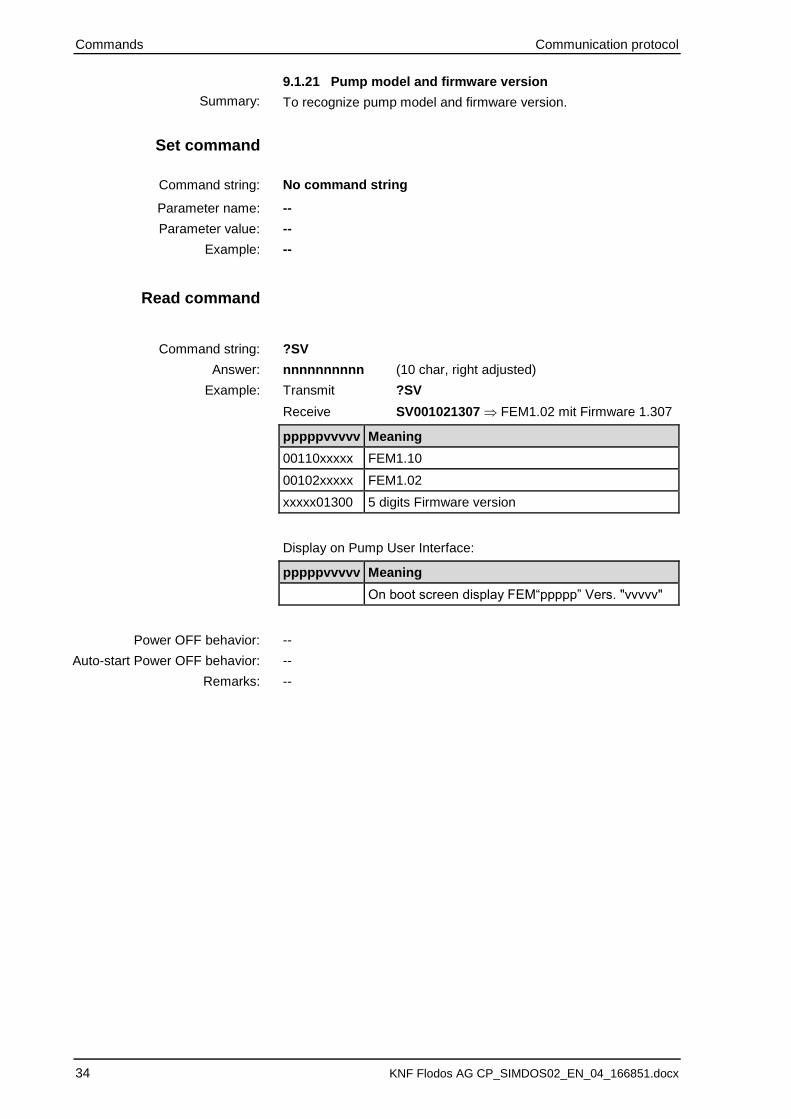
9.1.21 Pump model and firmware version
To recognize pump model and firmware version.
No command string
--
--
--
?SV
nnnnnnnnnn (10 char, right adjusted)
Transmit ?SV
Receive SV001021307 FEM1.02 mit Firmware 1.307
pppppvvvvv Meaning
00110xxxxx FEM1.10
00102xxxxx FEM1.02
xxxxx01300 5 digits Firmware version
Display on Pump User Interface:
pppppvvvvv Meaning
On boot screen display FEM“ppppp” Vers. "vvvvv"
--
--
--
Summary:
Set command
Command string:
Parameter name:
Parameter value:
Example:
Read command
Command string:
Answer:
Example:
Power OFF behavior:
Auto-start Power OFF behavior:
Remarks:

Communication protocol Commands
KNF Flodos AG CP_SIMDOS02_EN_04_166851.docx 35 35
9.1.22 Communication check function
Communication check function. Returns pump address if commu-nication works correctly.
No command string
--
--
--
?SI
nn (2 digits, right adjusted)
Transmit ?SI
Receive 00 Factory default
nn Meaning
00 Corresponds to the pump address (Factory default)
01 … 98 Corresponds to the pump address
Display on Pump User Interface:
No Display
Value of SI is not saved
Value of SI is not saved
To solve communication problems read Chapter 0, 6, 7 and 10
Summary:
Set command
Command string:
Parameter name:
Parameter value:
Example:
Read command
Command string:
Answer:
Example:
Power OFF behavior:
Auto-start Power OFF behavior:
Remarks:
Commands Communication protocol
36 KNF Flodos AG CP_SIMDOS02_EN_04_166851.docx
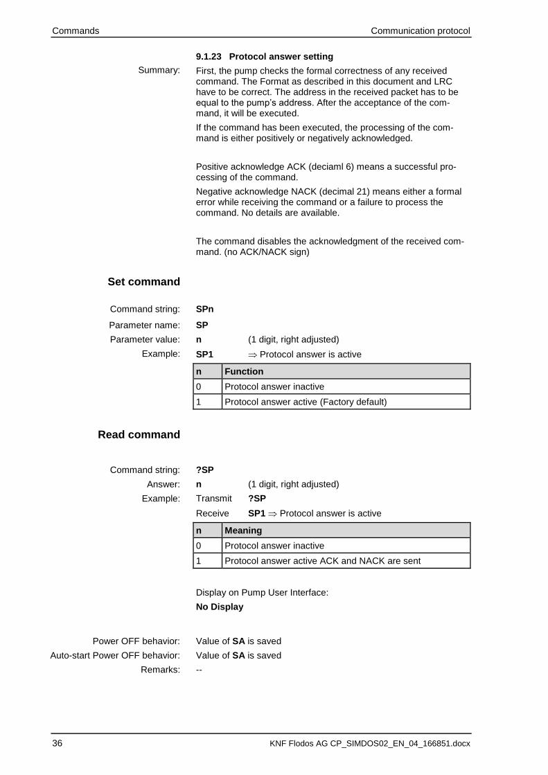
9.1.23 Protocol answer setting
First, the pump checks the formal correctness of any received command. The Format as described in this document and LRC have to be correct. The address in the received packet has to be equal to the pump’s address. After the acceptance of the com-mand, it will be executed.
If the command has been executed, the processing of the com-mand is either positively or negatively acknowledged.
Positive acknowledge ACK (deciaml 6) means a successful pro-cessing of the command.
Negative acknowledge NACK (decimal 21) means either a formal error while receiving the command or a failure to process the command. No details are available.
The command disables the acknowledgment of the received com-mand. (no ACK/NACK sign)
SPn
SP
n (1 digit, right adjusted)
SP1 Protocol answer is active
n Function
0 Protocol answer inactive
1 Protocol answer active (Factory default)
?SP
n (1 digit, right adjusted)
Transmit ?SP
Receive SP1 Protocol answer is active
n Meaning
0 Protocol answer inactive
1 Protocol answer active ACK and NACK are sent
Display on Pump User Interface:
No Display
Value of SA is saved
Value of SA is saved
--
Summary:
Set command
Command string:
Parameter name:
Parameter value:
Example:
Read command
Command string:
Answer:
Example:
Power OFF behavior:
Auto-start Power OFF behavior:
Remarks:

Communication protocol Commands
KNF Flodos AG CP_SIMDOS02_EN_04_166851.docx 37 37
9.1.24 Initialize the pump (new start)
Reset the pump similar to power OFF/power ON. (After a severe error like motor error or overpressure)
IN
no parameter value
IN Pump will be restarted (as power OFF/power ON)
No command string
--
--
Display on Pump User Interface:
No Display
Display
Pump displays boot screen
--
--
--
Summary:
Set command
Parameter name:
Parameter value:
Example:
Read command
Command string:
Answer:
Example:
Power OFF behavior:
Auto-start Power OFF behavior:
Remarks:
Commands Communication protocol
38 KNF Flodos AG CP_SIMDOS02_EN_04_166851.docx
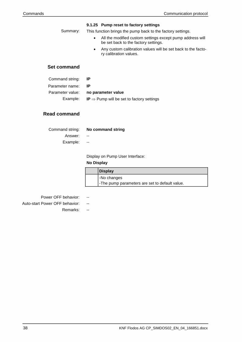
9.1.25 Pump reset to factory settings
This function brings the pump back to the factory settings.
• All the modified custom settings except pump address will be set back to the factory settings.
• Any custom calibration values will be set back to the facto-ry calibration values.
IP
IP
no parameter value
IP Pump will be set to factory settings
No command string
--
--
Display on Pump User Interface:
No Display
Display
-No changes
-The pump parameters are set to default value.
--
--
--
Summary:
Set command
Command string:
Parameter name:
Parameter value:
Example:
Read command
Command string:
Answer:
Example:
Power OFF behavior:
Auto-start Power OFF behavior:
Remarks:
Communication protocol Commands
KNF Flodos AG CP_SIMDOS02_EN_04_166851.docx 39 39
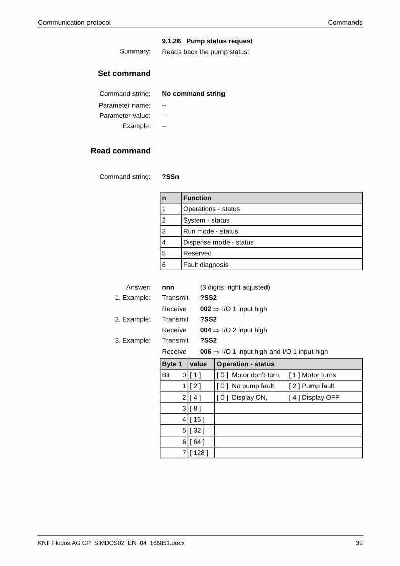
9.1.26 Pump status request
Reads back the pump status:
No command string
--
--
--
?SSn
nnn (3 digits, right adjusted)
Transmit ?SS2
Receive 002 I/O 1 input high
Transmit ?SS2
Receive 004 I/O 2 input high
Transmit ?SS2
Receive 006 I/O 1 input high and I/O 1 input high
Byte 1 value Operation - status
Bit 0 [ 1 ] [ 0 ] Motor don’t turn, [ 1 ] Motor turns
1 [ 2 ] [ 0 ] No pump fault, [ 2 ] Pump fault
2 [ 4 ] [ 0 ] Display ON, [ 4 ] Display OFF
3 [ 8 ]
4 [ 16 ]
5 [ 32 ]
6 [ 64 ]
7 [ 128 ]
Summary:
Set command
Command string:
Parameter name:
Parameter value:
Example:
Read command
Command string:
n Function
1 Operations - status
2 System - status
3 Run mode - status
4 Dispense mode - status
5 Reserved
6 Fault diagnosis
Answer:
1. Example:
2. Example:
3. Example:

Commands Communication protocol
40 KNF Flodos AG CP_SIMDOS02_EN_04_166851.docx
Byte 2 value System - status
Bit 0 [ 1 ] [ 0 ] motor not adjusted, [ 1 ] motor adjusted
1 [ 2 ] [ 0 ] I/O 1 input low, [ 2 ] I/O 1 input high
2 [ 4 ] [ 0 ] I/O 2 input low, [ 4 ] I/O 2 input high
3 [ 8 ] [ 0 ] motor not on UT, [ 8 ] motor on UT
4 [ 16 ]
5 [ 32 ]
6 [ 64 ]
7 [ 128 ]
Byte 3 value Run mode - status
Bit 0 [ 1 ] [ 0 ] RUN-mode stopped [ 1 ] RUN-mode started
1 [ 2 ]
2 [ 4 ]
3 [ 8 ]
4 [ 16 ]
5 [ 32 ]
6 [ 64 ]
7 [ 128 ]
Byte 4 value Dispense mode - status
Bit 0 [ 1 ] [ 0 ] Dispense-mode stopped
[ 1 ] Dispense-mode started
1 [ 2 ]
2 [ 4 ]
3 [ 8 ] [ 0 ] user stop active
[ 8 ] user stop NOT active
4 [ 16 ]
5 [ 32 ]
6 [ 64 ]
7 [ 128 ]
Byte 6 value Fault diagnosis
Bit 0 [ 1 ] [ 1 ] Overpressure,
1 [ 2 ] [ 2 ] Reserved
2 [ 4 ] [ 4 ] Reserved
3 [ 8 ] [ 8 ] Analog signal under 4 mA
4 [ 16 ] [ 16 ] Power supply failure
5 [ 32 ] [ 32 ] Motor error
6 [ 64 ] [ 64 ] Temperature exceeded
7 [ 128 ] [ 128 ] No encoder sensor signal
See section 10.2
Remarks:
Communication protocol Commands
KNF Flodos AG CP_SIMDOS02_EN_04_166851.docx 41 41
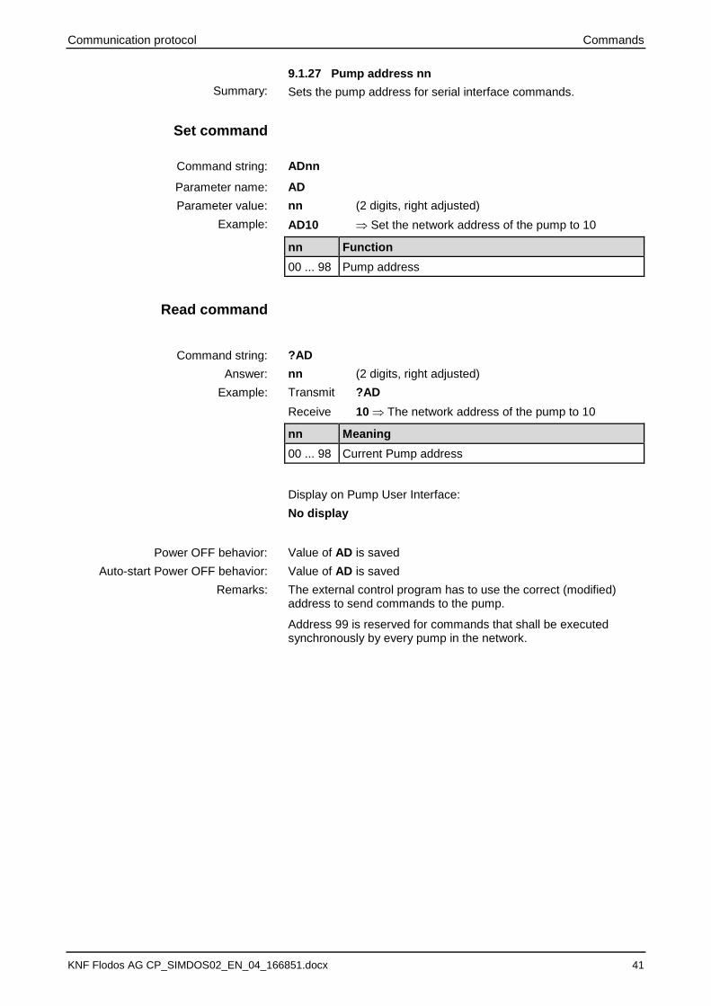
9.1.27 Pump address nn
Sets the pump address for serial interface commands.
ADnn
AD
nn (2 digits, right adjusted)
AD10 Set the network address of the pump to 10
nn Function
00 ... 98 Pump address
?AD
nn (2 digits, right adjusted)
Transmit ?AD
Receive 10 The network address of the pump to 10
nn Meaning
00 ... 98 Current Pump address
Display on Pump User Interface:
No display
Value of AD is saved
Value of AD is saved
The external control program has to use the correct (modified) address to send commands to the pump.
Address 99 is reserved for commands that shall be executed synchronously by every pump in the network.
Summary:
Set command
Command string:
Parameter name:
Parameter value:
Example:
Read command
Command string:
Answer:
Example:
Power OFF behavior:
Auto-start Power OFF behavior:
Remarks:
Commands Communication protocol
42 KNF Flodos AG CP_SIMDOS02_EN_04_166851.docx
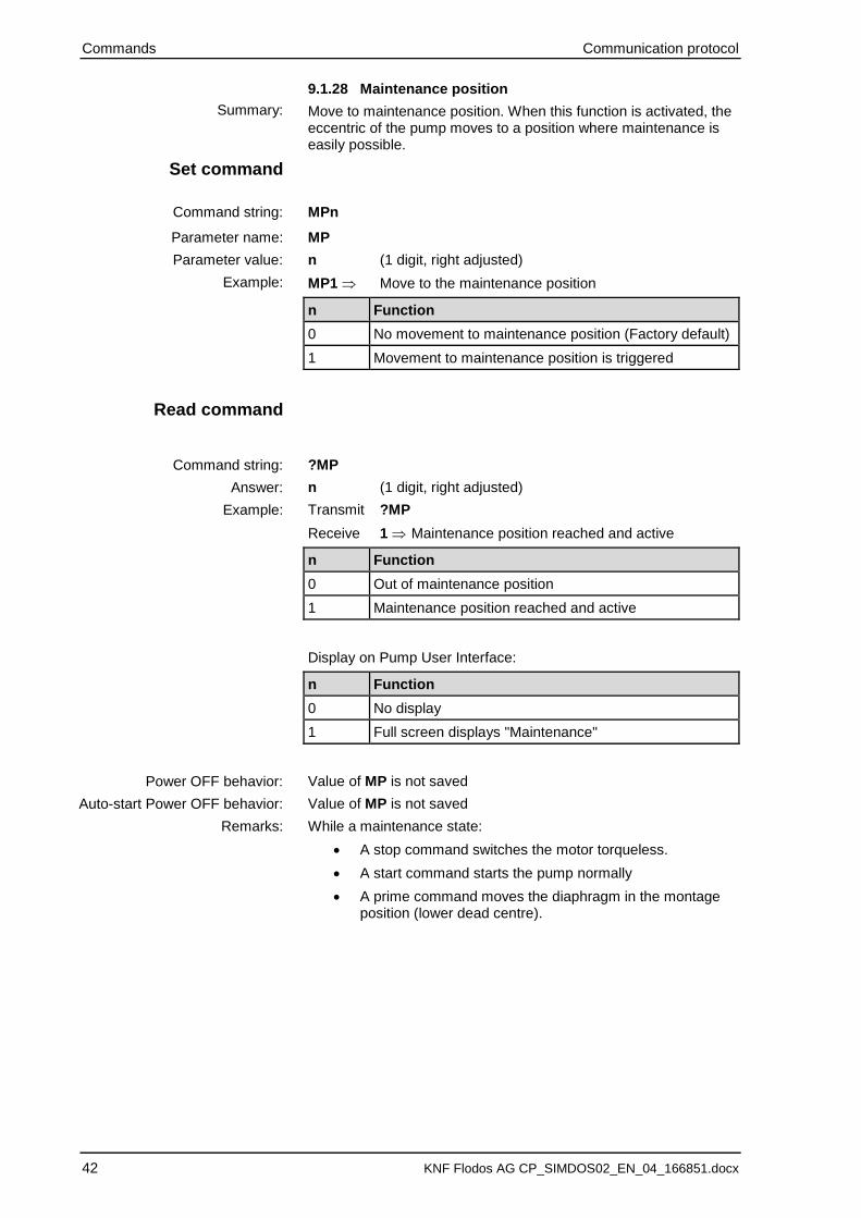
9.1.28 Maintenance position
Move to maintenance position. When this function is activated, the eccentric of the pump moves to a position where maintenance is easily possible.
MPn
MP
n (1 digit, right adjusted)
MP1 Move to the maintenance position
n Function
0 No movement to maintenance position (Factory default)
1 Movement to maintenance position is triggered
?MP
n (1 digit, right adjusted)
Transmit ?MP
Receive 1 Maintenance position reached and active
n Function
0 Out of maintenance position
1 Maintenance position reached and active
Display on Pump User Interface:
n Function
0 No display
1 Full screen displays "Maintenance"
Value of MP is not saved
Value of MP is not saved
While a maintenance state:
• A stop command switches the motor torqueless.
• A start command starts the pump normally
• A prime command moves the diaphragm in the montage position (lower dead centre).
Summary:
Set command
Command string:
Parameter name:
Parameter value:
Example:
Read command
Command string:
Answer:
Example:
Power OFF behavior:
Auto-start Power OFF behavior:
Remarks:

Communication protocol Troubleshooting
KNF Flodos AG CP_SIMDOS02_EN_04_166851.docx 43 43
10 Troubleshooting
10.1 Communication problems
Check if pump is powered
Check connectivity
• Make sure that the cables are connected
• Choose the COM port at the PC which is connected to the USB to R232 Adaptor
Check COM port interface settings (see Section 5)
Check pump address, the default address is 00 (see also section 9.1.22)
If there is no answer,
• Make sure that’s only one pump active in the network
Name STX Address Cmd str ETX LRC
Example 2 9 9 A D ! 00 3 37
=>Every active pump in the network will be readdressed with 00.
• Check:
Name STX Address Cmd str ETX LRC
Example 2 9 9 ? S I 3 36
Meaning Ack STX Data ETX LRC
Example #6 2 0 0 3 1
=>The Pump address is 00.
If the address has to be changed, make sure, that the mes-sage is send to the right address.
10.2 Displaying of error messages
Display Description Fault remedy
Error 1
Motor
Control deviation too high, motor is over-loaded
➢ Pump blocked
➢ Switch pump on / off
Error 2
Temperature
Motor overheating ➢ Allow pump to cool
➢ Reduce ambient tempera-ture
Error 3
Supply
Supply voltage is less than 21.6 V ➢ Supply with 24 V and suffi-cient power
Error 4
Encoder
Position measuring malfunction ➢ Switch pump on / off
Error 5
4 – 20 mA
Analog set point setting less than 2 mA ➢ Check control signal
➢ Check cable
Error 6
Flash
Error in memory ➢ Switch pump on / off
Error 7
Overpressure
System pressure exceeds 7 bar ➢ Check pump for closed valves and blocked filters
Transmit
Transmit
Receive
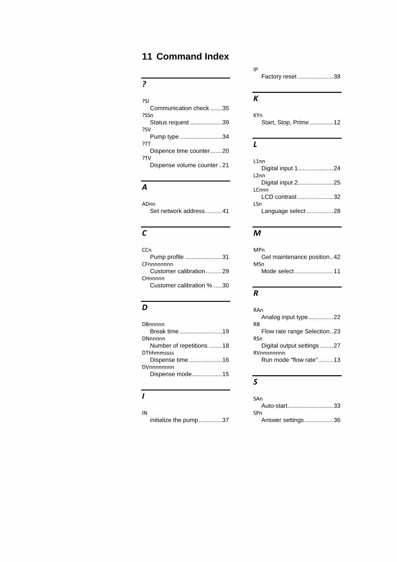
11 Command Index
?
?SI Communication check ....... 35
?SSn Status request ................... 39
?SV Pump type ......................... 34
?TT Dispence time counter ....... 20
?TV Dispense volume counter .. 21
A
ADnn Set network address .......... 41
C
CCn Pump profile ...................... 31
CFnnnnnnnn Customer calibration .......... 29
CHnnnnn Customer calibration % ..... 30
D
DBnnnnn Break time ......................... 19
DNnnnnn Number of repetitions ........ 18
DThhmmssss Dispense time .................... 16
DVnnnnnnnn Dispense mode .................. 15
I
IN initialize the pump .............. 37
IP Factory reset ..................... 38
K
KYn Start, Stop, Prime .............. 12
L
L1nn Digital input 1 ..................... 24
L2nn Digital input 2 ..................... 25
LCnnn LCD contrast ..................... 32
LSn Language select ................ 28
M
MPn Get maintenance position .. 42
MSn Mode select ....................... 11
R
RAn Analog input type ............... 22
RB Flow rate range Selection .. 23
RSn Digital output settings ........ 27
RVnnnnnnnn Run mode "flow rate" ......... 13
S
SAn Auto-start ........................... 33
SPn Answer settings ................. 36


www.knf.com
Communication protocol Revisionsbeschreibung
KNF Flodos CP_SIMDOS02_EN_04_166851.docx 49
Vorsicht: Diese Seite wird weder gedruckt noch in der Seitenan-sicht angezeigt. Sie ist nur sichtbar, wenn die Schaltfläche „ein-blenden/ausblenden“ in der Symbolleiste ‚Standard’ aktiviert ist. Bitte Freigabe und Revisionen lückenlos eintragen. Die neuste Version ist ebenfalls im Menu Datei/Eigenschaften/Anpassen einzutragen, damit die Revision auf dem Dokument in der Fusszei-le angezeigt wird.