chapter 10 status registers - arcelect.com
TRANSCRIPT

V.3400 10-1
Chapter 10Status Registers
S-REGISTERSMost modem configuration information is stored in a part of memory called status (S) registers. During operation this information is used to determine modem functions.
The information stored in the S-registers can be changed by the AT or V.25 command sets and by pushbuttons in response to the LCD prompt. These are the preferred methods. Some software programs also access the S-registers via the AT command set, but this action is transparent to the user. The command indicates which memory bit(s) to alter to select a particular option or to perform a certain function. The S-register values comprise the configuration profile.
CautionThe purpose of this tutorial is to show the versatility of option selection and register function. It is strongly recom-mended that the preferred methods of option selection be used. This tutorial uses S22 as the example register. Certain modems may use S22 differently or may not have an S22.
Generally the user should not directly alter S-register values. However, the user has the option of entering S-registers via ATS commands and directly altering the register value. This is called "writing" to the S-register. Writing to an S-register is not a preferred method and should only be used by programmers who need to manipulate S-registers so they can interact with a software program under development or some other similar action.
Certain S-registers cannot be altered by the ATS command series. These are called "read only" S-registers. Appendix E contains a listing of S-registers and indicates if they are read only or read and write.

Status Registers
10-2 V.3400
Figure 10-1 illustrates how the different inputs to an S-register (S22 in this case) are used to select a particular option. Bits 3 and 2 of S22control speaker options. Some communication software packages may use the AT command set. For example purposes bit values are arbitrary.
Bit values for S-registers must not be confused with the total register value. Bit values are counted separately for each option group, called bit mapping, while the register value is the cumulative decimal or hexa-decimal total. The decimal value counts all eight bits as a single group. Hexadecimal values split the bits into two groups of four each. Writing to an S-register changes the total value. Figure 10-2 illustrates the difference between decimal calculation and hexadecimal calculation.
Figure 10-1 Changing S-Register Values

Status Registers
V.3400 10-3
Figure 10-2 Calculating S-Register Values
S-REGISTER OPERATION Sn?, Sn?^Enter ATSn? to read a register value, where n=register number for a decimal value; or ATSn?^ for a hexadecimal value.
For example, to determine the current backspace character enter
ATS5?
The screen will show the ASCII value of the backspace character stored in register S5.
Changing Register Values Sn=v, Sn=^vTo change an option using ATS commands requires the operator to precalculate the revised decimal (or hexadecimal) total. Because of the chance of miscalculating the bit sum, causing unplanned option changes, writing to an S-register is discouraged. For operators who prefer this method of option selection a much simplified command that eliminates the decimal calculation is explained in the Individual Bit Command section.

Status Registers
10-4 V.3400
Enter ATSn=v to change a register value, where n = register number and v = decimal value; or ATSn=^v , where ^v = hexadecimal value.
☞ NoteNot all registers can be set by the ATSn=v (or ̂ v) command. Some registers are for reference only.
To change the escape character from + to the Esc key (ASCII value of 27)
Enter ATS2=27
To return the modem to the command mode press the Esc key three times:
(pause) Esc Esc Esc (pause)
Individual Bit Command Sn . # =vSome operators use AT commands as the primary method of changing S-register options. However, some options stored in registers do not have an associated AT command. For these options, the individual bit AT command can be used to change the setting of the bit controlling the option.
To change a single bit value within a register
Enter ATSn . # = v
where n = register number # = bit position 0 through 7 v = bit value 1 or 0
Example:
S-register 27, bit 2 selects between dial-up or leased line operation.
AT command method:
AT&L selects dial-up operation (sets S27 bit 2 to 0)
Status Registers
V.3400 10-5
AT&L1 selects leased line operation (sets S27 bit 2 to 1)
Individual bit method:
ATS27.2=0 selects dial-up operation (sets S27 bit 2 to 0)
ATS27.2=1 selects leased line operation (sets S27 bit 2 to 1)
☞ NoteThis way of selecting options can be used on all S-registers except read only registers.
Autoanswer S0This register turns the option on or off. Set the register to 0 to turn autoanswer off.
Set the register to any value other than zero (1-255) to turn autoanswer on. The number selected is the ring count the modem answers on. For example, if S0 equals 4, the modem answers the call on the fourth ring. The default value is 1.
Ring Count S1This register contains the ring count for a current incoming call and should not be changed. If developing communications software, the program can read the register to determine the ring total.
Escape Character S2The standard escape character is a + sign (ASCII value of 43). To change the character, set S2 to the desired ASCII value (0-255).
To disable the escape command, set S2 to any value greater than 127.
End-of-Line Character S3The standard end of line character is the carriage return (ASCII value of 13). This character ends each command as it is sent to the modem. It is also sent by the modem after each status message or number code.
To change the character, set S3 to the desired ASCII value (0-127).

Status Registers
10-6 V.3400
Line Feed Character S4The standard character is the line feed (ASCII value of 10). This char-acter is sent by the modem after each status message. To change it, set S4 as desired (0-127).
Backspace Character S5The standard character is the backspace (ASCII value of 8). To change it, set S5 to the desired value (0-127).
Pause Before Dialing S6When dial tone detection is disabled (command X, X1, or X3 in effect), the modem waits the number of seconds (0-255) stored in this register before dialing. The default value is 2 (seconds).
Pause for Ringback and Carrier Detection /Wait for 2nd Dial Tone S7
If no ringback is detected in the number of seconds in S7 (1-255), the modem disconnects and sends the NO CARRIER message or code. If ringback is detected, the modem begins to look for a carrier.
If no carrier is detected within the number of seconds in S7, the modem hangs up and sends the NO CARRIER message or code.
Values between 1 and 255 may be used. The default value is 30 (seconds).
Pause Interval for Comma S8When a dial command contains a comma, the modem pauses the number of seconds in S8.
Change S8 to change the basic pause interval (0-255), or use several commas in a row for greater delay during dialing.
The default value is 2 (seconds).
Carrier Detect Time S9S9 contains the amount of time (0-255) in 0.1 second increments the carrier must be present to be recognized. The default value is 6 (0.6 second). This timer can be extended to lessen the likelihood of false detection of carrier.

Status Registers
V.3400 10-7
Lost Carrier Detect Time S10S10 contains the amount of time (0-255) in 0.1 second increments carrier must be absent to be recognized as a loss of carrier. The default value is 14 (1.4 seconds).
DTMF Tone Duration S11S11 determines the length of DTMF tones. The period of silence is equal to the duration of the tone. The value of this register must be entered in multiples of 10. Default value is 80 (80 ms).
Escape Sequence Pause S12Using the escape sequence to return to command mode from data mode requires two pauses, one before and one after the escape characters.
The pauses prevent the modem from responding to a character sequence which might contain the escape sequence as part of its normal data transmission.
S12 contains the pause interval in 0.02 second increments. The factory setting is 50, equivalent to 1 second (50 x 0.02 sec). When S12 is 0 then timing is not a factor.
The timing between the 3 escape characters must be less than the pause interval or the escape sequence will not be detected. The data rate also affects the timing and must be taken into account when changing the pause interval.
To disable the escape command, set S2 to a value greater than 127 instead of changing S12. Values between 15 and 255 may be used for S12.
☞ NoteWhen S-registers have parallel AT commands, the commands are listed in the register tables as a cross refer-ence. If no command exists for the option the column is left blank.
S13Not used

Status Registers
10-8 V.3400
Bit Mapped S14
* default
☞ NoteRegisters that contain more than one option are called "bit mapped" registers.
S15Reserved
Bit Value Command Description
0 --- --- Reserved
1 01
EE1
Local character echo offLocal character echo on *
2 0 1
QQ1
Response messages on *Response messages off
3 01
VV1
Response messages as digit codesResponse messages as words *
4 0 1 Q2
Ignore *Response messages in originate mode only
5 0 1
TP
Tone dial *Pulse dial
6 0 1
H2--
Normal hang up *Not used
7 01
*OR1*OR
Forced answerNormal originate *

Status Registers
V.3400 10-9
System Tests S16This register contains the status of system test options.
S17Not used
Test Timeout S18The amount of time, in 1 second increments, that a diagnostic test will run is determined by the value assigned to S18 (0-255). A value of 0 disables the timer allowing a test to run indefinitely. The default value is 0.
S19, 20Not used
Bit Value Command Description
0 01
Analog loopback inactiveAnalog loopback in progress
1 Reserved
2 01
Digital loopback inactiveDigital loopback in progress
3 0
1
Remote digital loopback requested by other modem inactiveRemote digital loopback requested by other modem in progress
4 01
Remote digital loopback inactiveRemote digital loopback in progress
5 01
Self test remote digital loopback inactiveSelf test remote digital loopback in progress
6 01
Self test analog loopback inactiveSelf test analog loopback in progress
7 Reserved

Status Registers
10-10 V.3400
Bit Mapped S21
* default
Bit Value Command Description
6, 0 00 100111
&S&S1&S2&S3
DSR forced on *DSR on when onlineDSR off 5 seconds after disconnectDSR follows off hook (OH)
5, 1 00 100111
&C&C1&C2&C3
DCD always on *DCD on while carrier presentDCD on except for 5 seconds after disconnectDCD follows RTS on remote modem; not valid in reliable mode
2 01
&R&R1
CTS follows RTS by S26 delayCTS always on *
4, 3 00 01
1011
&D&D1
&D2&D3
Modem ignores DTR *Modem assumes command mode when DTR turns offModem hangs up when DTR turns offModem resets when DTR turns off
7 01
YY1
Long space disconnect disabledLong space disconnect enabled *

Status Registers
V.3400 10-11
Bit Mapped S22
* default
Bit Mapped S23
* default
S24Not used
Bit Value Command Description
1, 0 000110 11
LL1L2L3
Speaker volume lowSpeaker volume lowSpeaker volume medium *Speaker volume high
3, 2 0001 1011
MM1M2M3
Speaker offSpeaker on until carrier detect *Speaker always onSpeaker off when modem is dialing
6-4 000
001
010
011
100
X
X1
X2
X3
X4
CONNECT message only, blind dials, no busy detectCONNECT / appropriate code for rate, blind dials, no busy detectCONNECT / appropriate code for rate, waits for dial tone, no busy detectCONNECT / appropriate code for rate, blind dials, reports BUSYCONNECT / appropriate code for rate, waits for dial tone, reports BUSY *
7 01
&P&P1
Make / break ratio (US) 39/61 *Make / break ratio (UK) 33/67
Bit Value Command Description
0 01
&T5&T4
Remote digital loop request deniedRemote digital loop request granted *
5-1 --- --- Reserved
7, 6 00 011011
&G&G1&G2--
No guard tones *550 Hz guard tone1800 Hz guard toneNot used
Status Registers
10-12 V.3400
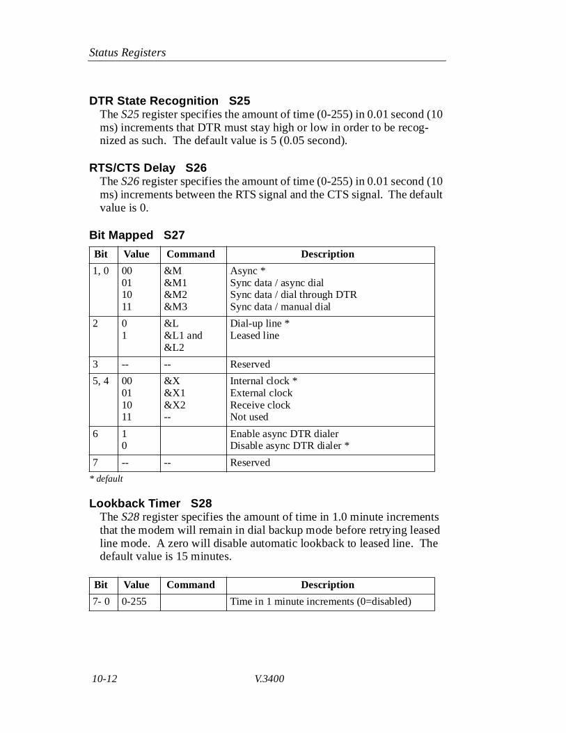
DTR State Recognition S25The S25 register specifies the amount of time (0-255) in 0.01 second (10 ms) increments that DTR must stay high or low in order to be recog-nized as such. The default value is 5 (0.05 second).
RTS/CTS Delay S26The S26 register specifies the amount of time (0-255) in 0.01 second (10 ms) increments between the RTS signal and the CTS signal. The default value is 0.
Bit Mapped S27
* default
Lookback Timer S28The S28 register specifies the amount of time in 1.0 minute increments that the modem will remain in dial backup mode before retrying leased line mode. A zero will disable automatic lookback to leased line. The default value is 15 minutes.
Bit Value Command Description
1, 0 000110 11
&M&M1&M2&M3
Async *Sync data / async dialSync data / dial through DTR Sync data / manual dial
2 01
&L&L1 and &L2
Dial-up line *Leased line
3 -- -- Reserved
5, 4 00 011011
&X&X1&X2--
Internal clock *External clockReceive clockNot used
6 10
Enable async DTR dialerDisable async DTR dialer *
7 -- -- Reserved
Bit Value Command Description
7- 0 0-255 Time in 1 minute increments (0=disabled)

Status Registers
V.3400 10-13
Bit Mapped S29
* default
Bit Mapped S30
* default
S31Reserved
Bit Value Command Description
0 01
*NT1*NT
Enable AT command set *Disable AT command set
1 01
*RO*RO1
Options retained at disconnect *Options restored at disconnect
2 01
*FT*FT1
Disable V.32 fast train *Enable V.32 fast train
6, 3 -- -- Reserved
7 0 1
*FB*FB1
DTE fallback disabled *DTE fallback enabled
Bit Value Command Description
0 -- -- Reserved
1 0 1
V.25 ASCII *V.25 EBCDIC
2 0 1
V.25 VAL enabled *V.25 VAL disabled
4, 3 -- -- Reserved
5 0 1
NRZ V.25 *NRZI V.25
7, 6 00011011
&M&M4&M5&M6
V.25 disabled *V.25 bisync enabledV.25 SDLC enabledV.25 Async enabled

Status Registers
10-14 V.3400
Bit Mapped S32
* default
S33Reserved
Bit Mapped S34
* default
DTR / Dial Backup Number to Dial S35Select the number to automatically dial (1-9 of stored numbers) for the modem to dial in DTR dialing or autodial backup.
S36-S38Reserved
Bit Value Command Description
0 01
&L1&L2
2-wire (leased line only) *4-wire (leased line only)
1 01
*LC1*LC2
Line current disconnect = shortLine current disconnect = long *
2 01
*LC*LC1 or*LC2
Line current disconnect = disableLine current disconnect = enable *
3 0 1
*DB*DB1
Dial backup = manual *Dial backup = automatic
7-4 -- -- Reserved
Bit Value Command Description
0 0 1
*AN*AN1
Bilateral analog = disable *Bilateral analog = enable
1 0 1
*DG*DG1
Bilateral digital = disable *Bilateral digital = enable
2 0 1
*LA*LA1
DTE commanded LAL = disable *DTE commanded LAL = enable
3 0 1
*RD*RD1
DTE commanded RDL = disable *DTE commanded RDL = enable
7-4 -- -- Reserved
Status Registers
V.3400 10-15
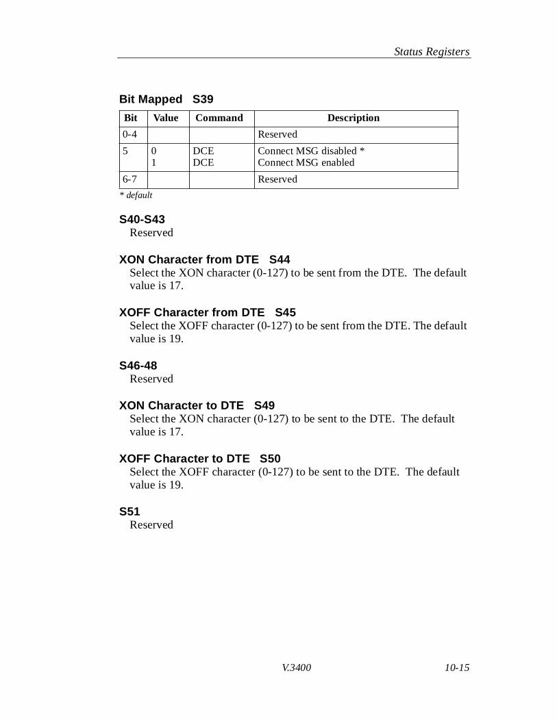
Bit Mapped S39
* default
S40-S43Reserved
XON Character from DTE S44Select the XON character (0-127) to be sent from the DTE. The default value is 17.
XOFF Character from DTE S45Select the XOFF character (0-127) to be sent from the DTE. The default value is 19.
S46-48Reserved
XON Character to DTE S49Select the XON character (0-127) to be sent to the DTE. The default value is 17.
XOFF Character to DTE S50Select the XOFF character (0-127) to be sent to the DTE. The default value is 19.
S51Reserved
Bit Value Command Description
0-4 Reserved
5 01
DCEDCE
Connect MSG disabled *Connect MSG enabled
6-7 Reserved

Status Registers
10-16 V.3400
Bit Mapped S52The S52 register selects leased line transmit level from 0 to -30 dBm in 1 dB increments.
* default
Automatic Rate Adaption Threshold S53
* default
Bit Value Command Description
4-0 0 to 30 *TLn (n=0-30)
Transmit level in dB (0 through -30 dBm) *
7-5 -- -- Reserved
Bit Value Command Description
1, 0 -- -- Reserved
3, 2 00 011011
%R%R1%R2%R3
Automatic rate adaption threshold disabled *Low BERMedium BERHigh BER
4 -- -- Reserved
5 01
Protocol Neg status disabled *Protocol Neg status enabled
6-7 -- -- Reserved

Status Registers
V.3400 10-17
Flow Control S54The S54 register selects the flow control options.
* default
S55Reserved
V.42 Compression Control S56
* default
Bit Value Command Description
1, 0 00011011
\Q\Q1\Q2\Q3
Disable DTE flow controlEnable DTE XON/XOFF flow control *Enable CTS flow control to the DTEEnable bilateral CTS/RTS flow control
2 -- -- Reserved
3 0 1
\G\G1
Disable modem port flow control *Enable modem port XON/XOFF flow control
4 0 1
\X\X1
No XON/XOFF characters to remote *Pass XON/XOFF characters to remote
6, 5 00011011
\Q4\Q5\Q6\Q7
Disable flow control from DCEEnable XON/XOFF flow control *Enable CTS flow control to the DTEEnable CTS flow control to the DTE
7 -- -- Reserved
Bit Value Command Description
1, 0 00011011
%C%C2%C3%C1
Compression disabledCompression enabled on transmit data onlyCompression enabled on receive data onlyCompression enabled on transmit and receive data *
7-2 -- -- Reserved

Status Registers
10-18 V.3400
Bit Mapped S57
* default
Inactivity Timer S58The S58 register specifies the number of minutes the modem waits before terminating a call when no data is sent or received. This register is active when in error control mode. 0 disables timer. Issue the \Tncommand to load inactivity timer, n=0-255 minutes.
* default
Break Control S59The S59 register determines the action taken when a break is encoun-tered. Refer to Break Control section in Chapter 6 for further explana-tion.
* default
Bit Value Command Description
0 0
1
*RC
*RC1
Standard number codes * 15 - 4800 bps 18 - 9600 bpsAlternate number codes 11 - 4800 bps 12 - 9600 bps
4-1 -- -- Reserved
5 01
Busy out disabled *Busy out enabled during LAL test mode(for private PBX use only)
7, 6 -- -- Reserved
Bit Value Command Description
7-0 01-255
\T\T (n=1-255)
Disable *Timer value in minutes
Bit Value Command Description
2-0 000001010011100101
\K\K1\K2\K3\K4\K5
Break option 0Break option 1Break option 2Break option 3Break option 4Break option 5 *
7-3 -- -- Reserved
Status Registers
V.3400 10-19
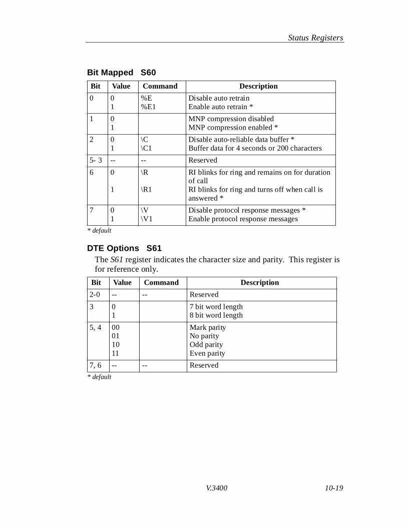
Bit Mapped S60
* default
DTE Options S61The S61 register indicates the character size and parity. This register is for reference only.
* default
Bit Value Command Description
0 01
%E%E1
Disable auto retrainEnable auto retrain *
1 01
MNP compression disabledMNP compression enabled *
2 0 1
\C\C1
Disable auto-reliable data buffer *Buffer data for 4 seconds or 200 characters
5- 3 -- -- Reserved
6 0
1
\R
\R1
RI blinks for ring and remains on for duration of callRI blinks for ring and turns off when call is answered *
7 0 1
\V\V1
Disable protocol response messages *Enable protocol response messages
Bit Value Command Description
2-0 -- -- Reserved
3 01
7 bit word length8 bit word length
5, 4 00011011
Mark parityNo parityOdd parityEven parity
7, 6 -- -- Reserved

Status Registers
10-20 V.3400
Disconnect Buffer Delay S62The S62 register determines the delay before disconnect, to allow buffers to empty, when disconnect conditions exist.
* default
Maximum Transmit Block Size S63The S63 register sets the maximum transmit block size.
* default
Auto-Reliable Fallback Character S64The S64 register stores the selected ASCII value of the auto-reliable fallback character.
* default
S65-66Reserved
Bit Value Command Description
7-0 01-255
%D%Dn
Buffer disabled *Disconnect buffer delay value (seconds)
Bit Value Command Description
7-0 63127191255
\A\A1\A2\A3
Maximum block size = 64Maximum block size = 128Maximum block size = 192Maximum block size = 256 *
Bit Value Command Description
7-0 01-127
%A%An
Disable auto-reliable fallback character *ASCII value 1-127
Status Registers
V.3400 10-21
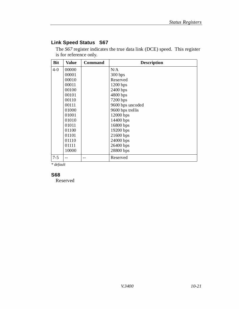
Link Speed Status S67The S67 register indicates the true data link (DCE) speed. This register is for reference only.
* default
S68Reserved
Bit Value Command Description
4-0 0000000001000100001100100001010011000111010000100101010010110110001101011100111110000
N/A300 bpsReserved1200 bps2400 bps4800 bps7200 bps9600 bps uncoded9600 bps trellis12000 bps14400 bps16800 bps19200 bps21600 bps24000 bps26400 bps28800 bps
7-5 -- -- Reserved

Status Registers
10-22 V.3400
DCE Independent Speed S69The S69 register selects the DCE independent rate operation. When S69is 0, DTE and DCE rates are equal and the maximum originate connect rate up to 14400 bps is determined by S80. When S69 is non-zero, the maximum originate connect rate is determined by S69.
* default
Operating Mode S70The S70 register determines the protocol operating mode and action taken on an MNP link attempt failure. LAPM is assigned highest priority.
Example: With \N7 selected the modem tries a LAPM connection first; if unsuccessful the modem tries an MNP connection; if also unsuc-cessful the modem connects in normal mode. Modes allowing protocol fallback are referred to as auto-reliable.
Bit Value Command Description
4-0 0000000001000110010000101001110100000110010010101000010010110110001101011100111110000
%B%B1%B2%B3%B4%B5%B6%B7%B8%B9%B10%B11%B12%B13%B14%B15%B16
Use rate indicated by S80300 bps1200 bps2400 bps4800 bps9600 bps uncoded9600 bps trellis7200 bps12000 bps14400 bps Reserved16800 bps19200 bps21600 bps24000 bps26400 bps28800 bps *
7-5 -- -- Reserved
Status Registers
V.3400 10-23
* default
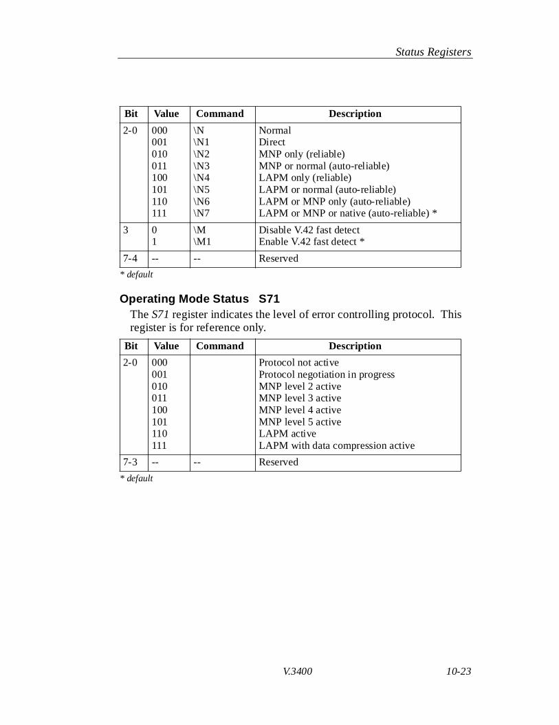
Operating Mode Status S71The S71 register indicates the level of error controlling protocol. This register is for reference only.
* default
Bit Value Command Description
2-0 000001010011100101110111
\N\N1\N2\N3\N4\N5\N6\N7
NormalDirectMNP only (reliable)MNP or normal (auto-reliable)LAPM only (reliable)LAPM or normal (auto-reliable)LAPM or MNP only (auto-reliable)LAPM or MNP or native (auto-reliable) *
3 01
\M\M1
Disable V.42 fast detectEnable V.42 fast detect *
7-4 -- -- Reserved
Bit Value Command Description
2-0 000001010011100101110111
Protocol not activeProtocol negotiation in progressMNP level 2 activeMNP level 3 activeMNP level 4 activeMNP level 5 activeLAPM activeLAPM with data compression active
7-3 -- -- Reserved

Status Registers
10-24 V.3400
Bit Mapped S72
* default
Password Timeout S73The length of time the remote user has to enter a password before the secure V.3400 drops the call.
* default
Callback Delay S74The length of time the secure modem waits to place the callback call after the remote user correctly enters a password and the call is dropped. Default is 15 seconds.
Callback Retry S75The number of times the modem will attempt to place the callback call to a remote user if the first attempt is unsuccessful.
Bit Value Command Description
0 01
\J\J1
Disable slaved DTE/DCE (constant speed DTE on) *Disable slaved DTE/DCE (constant speed DTE on)
1 -- -- Reserved
2 -- -- Reserved
3 01 &R2
CTS does not follow DCDCTS follows DCD
6-4 -- -- Reserved
7 01
Disable autocallback *Enable autocallback
Bit Value Command Description
7-0 0-255 Time in seconds (0 = disable)
Bit Value Command Description
7-0 0-255 Time in seconds (0 = disable)
Bit Value Command Description
7-0 0-255 Number of attempts to place the call

Status Registers
V.3400 10-25
Callback Retry Delay S76The length of time that the modem waits, after an unsuccessful attempt to connect to the remote unit at the programmed callback number, before trying to place the call again. Default is 15 seconds.
Lockout Threshold S77The number of incorrect remote user password attempts that can be made before the call is dropped.
Autocallback Timer S78The S78 register specifies the time in seconds that the modem waits before initiating autocallback. The default is 30 seconds.
Break Length S79The S79 register sets the length of the break sent to the DTE when a break signal is received. Range from 1-255 in 20 ms increments. Default is 35 (700 ms).
Bit Value Command Description
7-0 0-255 Time in seconds (0 = disable)
Bit Value Command Description
7-0 0-255 Number of incorrect password attempts (0 = disable)
Bit Value Command Description
7-0 0-255 Time in seconds before autocallback
Bit Value Command Description
7-0 0-255 \B\Bn
Send breakSet break length (n=1-255)

Status Registers
10-26 V.3400
Serial Port Speed S80The S80 register indicates the serial port speed.
* default
Bit Value Command Description
4-0 000010001000011001000010100110001110100001001010100101101100011010111001111100001000110010
300 bps600 bps1200 bps2400 bps4800 bps7200 bps *9600 bps12000 bps14400 bps16800 bps19200 bps21600 bps24000 bps26400 bps28800 bps38400 bps57600 bps115200 bps

Status Registers
V.3400 10-27
Minimum DCE Speed S81
* default
S82-S87Reserved
Bit Value Command Description
4-0 0000000001000110010000101001110100000110010010101000010010110110001101011100111110000
%L%L1%L2%L3%L4%L5%L6%L7%L8%L9%L10%L11%L12%L13%L14%L15%L16
DisabledDisabled *1200 bps2400 bps4800 bps9600 bps uncoded9600 bps trellis7200 bps12000 bps14400 bpsReserved16800 bps19200 bps21600 bps24000 bps26400 bps28800 bps
7-3 -- -- Reserved

Status Registers
10-28 V.3400
Modulation Type S88
S89-S90Reserved
Current Modulation S91
S92 - S94Reserved
Bit Value Command Description
3-0 0000000100100011010001010110011110001001101010111100
Auto modeV.21B103ReservedB212AV.22 bisV.27 (lease line only)ReservedV.29 (lease line only)ReservedV.33 (lease line only)V.32 bisV.34
7-4 Reserved
Bit Value Command Description
3-0 0000000100100011010001010110011110001001101010111100
Auto modeV.21B103ReservedB212AV.22 bisV.27 (lease line only)ReservedV.29 (lease line only)ReservedV.33 (lease line only)V.32 bisV.34
7-4 Reserved

Status Registers
V.3400 10-29
V.34 Settings S95
* default
V.34 Settings S96
* default
S97 - S100Reserved
Bit Value Command Description
0 01
Disable V.8 for non-V.34 answerEnable V.8 for non-V.34 answer *
3-1 -- Reserved
4 01
Disable non-linear encoding Enable non-linear encoding *
5 01
Disable pre-emphasis Enable pre-emphasis *
6 01
Disable constellationshaping Enable constellation shaping *
7 01
Precoding disabledPrecoding enabled*
Bit Value Command Description
4-0 -- Reserved
5 01
Disable asymmetric bit ratesEnable asymmetric bit rates *
6 -- Reserved
7 01
Disable TX power control Enable TX power control *

Status Registers
10-30 V.3400