cfd analysis and numerical aerodynamic … rotor varying with time in a transient state using cfd...
TRANSCRIPT
Abstract—Braking system is one of the important control
systems of an automotive. For many years, the disc brakes have been used in automobiles for safe retardation of the vehicles. During braking enormous amount of heat will be generated and for effective braking sufficient heat dissipation is essential. The thermal performance of disc brake depends upon the characteristics of the airflow around the brake rotor and hence the aerodynamics is an important in the region of brake components. A CFD analysis is carried out on the braking system as a case study to make out the behaviour of airflow distribution around the disc brake components using ANSYS CFX software. We are interested in the determination of the heat transfer coefficient (HTC) on each surface of a ventilated disc rotor varying with time in a transient state using CFD analysis, and then imported the surface film condition data into a corresponding FEM model for disc temperature analysis.
Keywords—CFD, gray cast iron ,heat flux, heat transfer coefficient
I. INTRODUCTION HE ever increasing need of effective transportations puts automobile manufacturers in a non-avoidable situation of
maintaining and improvement of safety systems. The brake system has always been one of the most critical active safety systems. Brake cooling is further an important aspect to consider for brake disc durability and performance.
The importance of convective cooling of a brake disc is an important factor since it can be significantly improved by trivial design changes and contributes to the major part of the total dissipated heat flux for normal driving conditions.
The braking system represents one of the most fundamental safety-critical components in modern passenger cars. Therefore, the braking system of a vehicle is undeniably important, especially in slowing or stopping the rotation of a wheel by pressing brake pads against rotating wheel discs [1].
A. Belhocine is with the Department of Mechanical Engineering,
University of Sciences and the Technology of Oran, L.P 1505 El -MNAOUER, USTO 31000 ORAN (Algeria) (corresponding author to provide phone: +213790092648 ; e-mail: belho2017@ gmail.com).
W. Z. Wan Omar, with Faculty of Mechanical Engineering, Universiti Teknologi Malaysia, 81310 UTM Skudai, Malaysia (e-mail: [email protected]).
A common technique to improve the brake cooling is using
a ventilated brake disc. Figure I show the scheme of a disc brake. It improves the convective cooling by means of the air passages separating the braking surfaces. For years, ventilated brake rotors have been used for their weight savings and additional convective heat transfer from the air channels between the rotor hub cheeks (passages lacking in solid rotors). However, the amount of additional cooling due to this internal air flow is not well defined and depends on the individual brake rotor’s geometry and the cooling air flow conditions around the brake assembly. Therefore flow analysis and heat dissipation have fascinated many researchers. Earlier work has addressed both aerodynamic [2, 3, 5, 6, 9] and heat transfer [4, 5, 7, 8] aspects of ventilated and solid discs.
The investigation of the localized thermal phenomena such as hot spotting and hot banding [10,11] requires a fully coupled thermo-elastic analysis and thus, it is beyond the scope of the current study. This separate work is underway to include the localized thermal effects in the proposed design process and will be reported in the future. Braking performance of a vehicle can significantly be affected by the temperature rise in the brake components. The frictional heat generated at the interface of the disc and the pads can cause a high temperature. Particularly, the temperature may exceed the critical value for a given material, which leads to undesirable effects, such as brake fade, local scoring, thermo-elastic instability, premature wear, brake fluid vaporization, bearing failure, thermal cracks, and thermally excited vibration [12].
Dufrénoy [13] proposed a structural macro model of the thermo mechanical behaviour of the disc brake, taking into account the real three-dimensional geometry of the disc–pad couple. Contact surface variations, distortions and wear are taken into account. Formation of hot spots, as well as non -uniform distribution of the contact pressure is an unwanted effect emerging in disc brakes in the course of braking or during engagement of a transmission clutch. In work carried out by Söderberg and Andersson [14] a three-dimensional finite element model of the brake pad and the rotor were developed primarily for the calculations of the contact pressure distribution of the pad on to the rotor. If the sliding velocity is high enough, this effect can become unstable and can result in disc material damage, frictional vibration, wear, etc. [15].
CFD analysis and numerical aerodynamic investigations of automotive disc brake rotor
A. Belhocine and W.Z. Wan Omar
T
INTERNATIONAL JOURNAL OF MECHANICS Volume 11, 2017
ISSN: 1998-4448 251

Gao and Lin [16] stated that there is considerable evidence that shows the contact temperature is an integral factor reflecting the specific power friction influence of the combined effect of load, speed, friction coefficient, and the thermo physical and durability properties of the materials of a frictional couple. Lee and Yeo [17] reported that uneven distribution of temperature at the surfaces of the disc and friction pads brings about thermal distortion, which is known as coning and found to be the main cause of Judder and disc thickness variation (DTV). Ouyang et al [18] in their recent work found that temperature could also affect the vibration level in a disc brake assembly. In a recent work, Ouyang et al [18] and Hassan et al [19] employed the finite element approach to investigate the thermal effects on disc brake squeal using dynamic transient and complex eigenvalue analysis, respectively. Braking system is the single most important safety feature of every vehicle on the road. The ability of the braking system to bring a vehicle to a safe controlled stop is absolutely essential in preventing accidental vehicle damage and personal injury. The braking system is composed of many parts, including friction pads on each wheel, a master cylinder, wheel cylinders, and a hydraulic control system [20]. A disc brake consists of a cast-iron disc ,which rotates with the wheel, a caliper fixed to the steering knuckle, and friction material (brake pads). When the braking process occurs, the hydraulic pressure forces the piston and therefore the pads and disc brake are in sliding contact. Set up force resists the movement and the vehicle slows down or eventually stops. Friction between the disc and pads always opposes motion and the heat is generated due to conversion of the kinetic energy [21]. The three-dimensional simulation of thermo-mechanical interactions on the automotive brake, showing the transient thermo-elastic instability phenomenon, is presented for the first time in this academic community [22].
Recently, Belhocine and Wan Omar [23] investigated the structural and mechanical behavior of a three-dimensional disc-pad model during the braking process under dry contacts slipping conditions. After that, Belhocine [24] investigated the structural and contact behaviors of the brake disc and pads during the braking phase with and without thermal effects.
When a vehicle brake, a part of the friction temperature escapes into the air through convection and radiation. Therefore, the determination of heat transfer coefficients is very important. It is, however, very difficult to calculate them precisely because they depend on the shape of the braking system, the speed of movement of the vehicle, and consequently on the air circulation. Here the modeling of convection proves to be the main problem because it is related to the aerodynamic conditions of the disc.
In this work, we are interested in this part of the calculation of the heat exchange coefficient (h). This parameter must be evaluated to visualize the three-dimensional distribution of the temperature of the disc. The strategy of calculation is based on the software ANSYS CFX 11 which the numerical simulation of the transient thermal field is carried out by using ANSYS
[25]. A comparison was made between the temperature of full and ventilated brake disc showing the importance of cooling mode in the design of automobile discs.
II. PRINCIPLE OF DISC BRAKES
The principle of a disc brake is very simple: A metal disc, the rotor, is firmly mounted to the rotating wheel. The pads grip the rotating disc when the brakes are applied. The disc brake system consists of the following parts (see Figure 1): • The pads - two flat elements made of friction material. They
run perpendicular to the disc and grip it when a brake force is applied.
Fig.1. Parts of the brake system
The rubbing on the moving disc surface causes it to slow down. • The caliper - which contains a piston that presses the pads
against the disc surface. The caliper is mounted to the chassis.
• The rotor - which is mounted to the hub and is therefore rotating with the wheel.
The vehicle in motion can be considered as a permanent energy conversion system: Chemical energy is transformed through combustion into mechanical energy. This energy is then transformed into kinetic or potential energy of a car. When braking, the vehicle’s kinetic energy is entirely converted into thermal energy by the frictional interaction between brake pads and the rotor.
The generated heat is distributed between the rotor and the pads. This partition between pads and disc depends highly on the physical-chemical properties of the two materials. Over 95% of this thermal energy flows into the rotor and is stored, conducted to the hub and the wheel, and for longer brake applications convected to the surrounding air.
III. BRAKE DISC TYPES There are two types of discs: full discs and ventilated discs. The full discs, of simple geometry and therefore of simple manufacture, are generally placed on the rear axle of the car. They consist simply of a solid crown connected to a "bowl" which is fixed to the hub of the car (Fig.2.a). Ventilated discs of more complex geometry appeared later. They are mostly on the front axle. However, they are increasingly in the rear and
INTERNATIONAL JOURNAL OF MECHANICS Volume 11, 2017
ISSN: 1998-4448 252
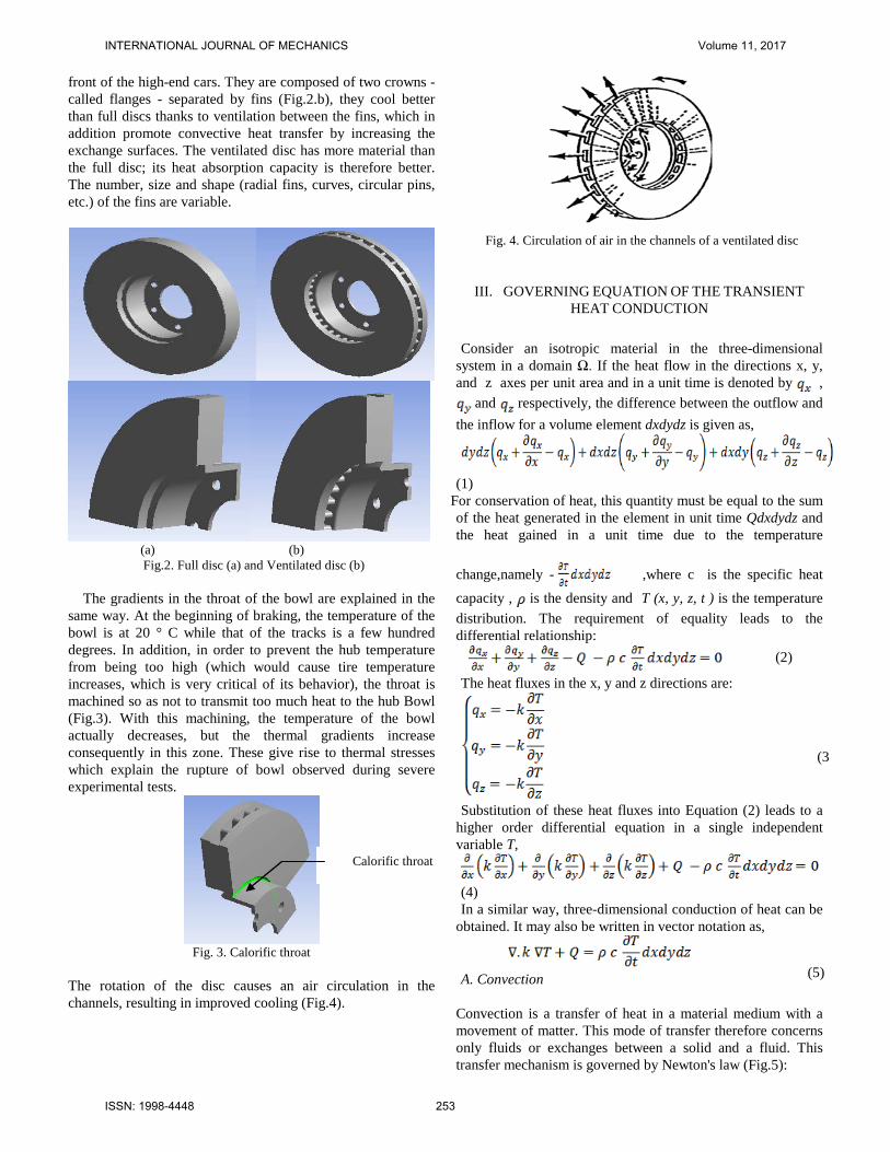
front of the high-end cars. They are composed of two crowns - called flanges - separated by fins (Fig.2.b), they cool better than full discs thanks to ventilation between the fins, which in addition promote convective heat transfer by increasing the exchange surfaces. The ventilated disc has more material than the full disc; its heat absorption capacity is therefore better. The number, size and shape (radial fins, curves, circular pins, etc.) of the fins are variable.
(a) (b) Fig.2. Full disc (a) and Ventilated disc (b)
The gradients in the throat of the bowl are explained in the
same way. At the beginning of braking, the temperature of the bowl is at 20 ° C while that of the tracks is a few hundred degrees. In addition, in order to prevent the hub temperature from being too high (which would cause tire temperature increases, which is very critical of its behavior), the throat is machined so as not to transmit too much heat to the hub Bowl (Fig.3). With this machining, the temperature of the bowl actually decreases, but the thermal gradients increase consequently in this zone. These give rise to thermal stresses which explain the rupture of bowl observed during severe experimental tests.
Fig. 3. Calorific throat
The rotation of the disc causes an air circulation in the channels, resulting in improved cooling (Fig.4).
Fig. 4. Circulation of air in the channels of a ventilated disc
III. GOVERNING EQUATION OF THE TRANSIENT HEAT CONDUCTION
Consider an isotropic material in the three-dimensional
system in a domain Ω. If the heat flow in the directions x, y, and z axes per unit area and in a unit time is denoted by ,
and respectively, the difference between the outflow and the inflow for a volume element dxdydz is given as,
(1) For conservation of heat, this quantity must be equal to the sum of the heat generated in the element in unit time Qdxdydz and the heat gained in a unit time due to the temperature
change,namely - ,where c is the specific heat capacity , is the density and T (x, y, z, t ) is the temperature distribution. The requirement of equality leads to the differential relationship: (2)
The heat fluxes in the x, y and z directions are:
Substitution of these heat fluxes into Equation (2) leads to a
higher order differential equation in a single independent variable T,
(4) In a similar way, three-dimensional conduction of heat can be
obtained. It may also be written in vector notation as,
A. Convection
Convection is a transfer of heat in a material medium with a movement of matter. This mode of transfer therefore concerns only fluids or exchanges between a solid and a fluid. This transfer mechanism is governed by Newton's law (Fig.5):
Calorific throat
(3
(5)
INTERNATIONAL JOURNAL OF MECHANICS Volume 11, 2017
ISSN: 1998-4448 253
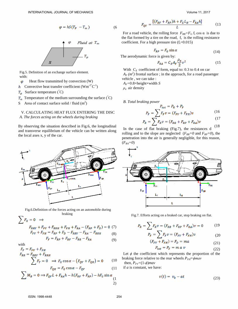
Fig.5. Definition of an exchange surface element. with: Heat flow transmitted by convection (W) Convective heat transfer coefficient (Wm-2°C-1) Surface temperature (°C) Temperature of the medium surrounding the surface (°C)
S Area of contact surface solid / fluid (m2) V. CALCULATING HEAT FLUX ENTERING THE DISC
A. The forces acting on the wheels during braking
By observing the situation described in Fig.6, the longitudinal and transverse equilibrium of the vehicle can be written along the local axes x, y of the car.
Fig.6.Definition of the forces acting on an automobile during
braking
(7)
(8) (9)
with
(12)
For a road vehicle, the rolling force FRR=FG fr cos α is due to
the flat formed by a tire on the road, fr is the rolling resistance coefficient. For a high pressure tire (fr=0.015)
(14)
The aerodynamic force is given by:
With CX coefficient of form, equal to: 0.3 to 0.4 on car AF (m2) frontal surface ; in the approach, for a road passenger
vehicle , we can take : AF=0.8×height×width S ρa air density B. Total braking power
In the case of flat braking (Fig.7), the resistances due to
rolling and to the slope are neglected (FRR=0 and FRP=0), the penetration into the air is generally negligible, for this reason, (FRA=0)
Fig.7. Efforts acting on a braked car, stop braking on flat.
(21)
(22) Let ϕ the coefficient which represents the proportion of the
braking force relative to the rear wheels PFH=ϕmav then, PFV=(1-ϕ)mav if a is constant, we have:
(23)
(6
(10
(11
(13
(15
(16
(17
(18
(19
(20
INTERNATIONAL JOURNAL OF MECHANICS Volume 11, 2017
ISSN: 1998-4448 254
(24) The braking power delivered to the brake disc is equal to half
the total power:
At time t = 0, we have
The braking efficiency is then defined by the ratio between
the deceleration (a) and the acceleration (g):
The purpose of the brake discs is to dissipate mechanical
energy into heat. For trains or cars, it is the kinetic energy of the vehicle that is dissipated by the friction of the skates on the discs. The disc pad assembly heats up under this action and cools in the ambient air. As these brakes are repeated, the brake discs are subjected to thermomechanical fatigue. In the automotive industry, many studies have shown that braking can generate temperatures in excess of 700 ° C in a matter of seconds. Considering that the brake disc can totally absorb the amount of heat produced.
The expression of the transformed friction power per unit area
is thus:
The quantity Q’
v characterizes the heat flux injected into the disc, it must therefore be located only on the actual contact
surface. Where Ad the disc surface swept by a brake pad. If we introduce the factor of exploitation εp of the friction surface
Thus, the equation of the initial thermal flow of friction
entering the disc, which is calculated as follows:
C. Heat Flux Entering the Disc
In the course of braking, the kinetic energy and potential energy of the automobile are converted into thermal energy through the frictional heating behaviour between the interfaces of the friction pair: the frictional heat is generated on the interfaces of the brake disc and brake pads. The initial heat flux into the rotor face is directly calculated using the following formula [26]:
Where z=a/g is the braking effectiveness, a is the deceleration of the vehicle [ms-2] and g is the acceleration of gravity (9.81) [ms-2]. Our work consists in studying the thermal behavior of a three-dimensional brake disc, which includes the heat flux generated inside the brake disc, the maximum and minimum temperatures, and so on. The scenario analyzed is a stop brake. In practice, the braking system bathes in an air flow, more or less forced according to the system, which participates in the cooling of the disc and of the plates. This air flow is governed by the laws of aerodynamics. The values of the heat exchange coefficient h as a function of time are calculated using the ANSYS CFX code. These values will be used to determine the thermal behavior of the disc in transient mode.
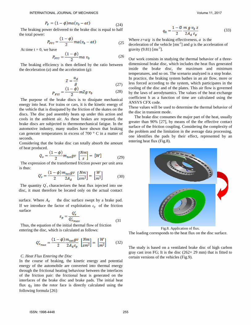
The brake disc consumes the major part of the heat, usually greater than 90% [27], by means of the the effective contact surface of the friction coupling. Considering the complexity of the problem and the limitation in the average data processing, one identifies the pads by their effect, represented by an entering heat flux (Fig.8).
Fig.8. Application of flux.
The loading corresponds to the heat flux on the disc surface. The study is based on a ventilated brake disc of high carbon gray cast iron FG; It is the disc (262× 29 mm) that is fitted to certain versions of the vehicles (Fig.9).
(27) (28)
(29)
(30)
(31
(32)
(25
(26
(33)
INTERNATIONAL JOURNAL OF MECHANICS Volume 11, 2017
ISSN: 1998-4448 255

Fig.9. Ventilated disc (contour view).
To facilitate comparison of simulation results, the geometric dimensions of the two disc variants, full disc and ventilated disc are the same The dimensions and the parameters used in the thermal calculation are described in Table 1.
Table.1. Geometrical dimensions and application parameters of automotive braking.
Inner disc diameter, mm 66
Outer disc diameter, mm 262
Disc thickness (TH), mm 29
Disc height (H), mm 51
Vehicle mass m , kg 1385
Initial speed v0 , m/s 28
Deceleration a , m/s2 8
Braking time tb , s 3.5
Effective rotor radius Rrotor ,mm 100.5 Rate distribution of the braking forces ϕ, %
20 Factor of charge distribution of the disc εp 0.5
Surface disc swept by the pad Ad, mm2 35993
The disc material is gray cast iron (FG 15) with high carbon content [28], good thermophysical characteristics, whose thermo-elastic characteristics adopted in this simulation in the transient analysis of the disc are listed in Table 2 . It is very difficult to exactly model the brake disc, in which there are still researches are going on to find out transient thermal behavior of disc brake during braking applications. There is always a need of some assumptions to model any complex geometry. These assumptions are made, keeping in mind the difficulties involved in the theoretical calculation and the importance of the parameters that are taken and those which are ignored. In modeling we always ignore the things that are of less importance and have little impact on the analysis. The assumptions are always made depending upon the details and accuracy required in modeling. To simplify the analysis, several assumptions have also been made as follows [29]:
• All kinetic energy at disc brake rotor surface is converted into frictional heat or heat flux.
• The heat transfer involved for this analysis only conduction and convection process. This heat transfer radiation can be neglected in this analysis because of small amount which is 5% to 10% [30].
• The disc material is considered as homogeneous and isotropic.
• The domain is considered as axis-symmetric. • Inertia and body force effects are negligible during the
analysis. • The disc is stress free before the application of brake. • In this analysis, the ambient temperature and initial
temperature has been set to 20°C • All other possible disc brake loads are neglected. • Only certain parts of disc brake rotor will apply with
convection heat transfer such as cooling vanes area, outer ring diameter area and disc brake surface
The thermal conductivity and specific heat are a function of temperature, Figures 10 and 11.
Table 2. Thermoelastic properties used in simulation.
Material Properties Disc Thermal conductivity, k (W/m°C) 57 Density, (kg/m3) 7250 Specific heat, c (J/Kg. °C)
460 Poisson’s ratio, 0.28 Thermal expansion, (10-6 / °C) 10.85 Elastic modulus, E (GPa) 138
0 100 200 300 400 500 600 700 800 900
35
40
45
50
55
60
Therm
al cond
uctivit
y W/m
°C
Temperature °C
Fig.10. Thermal conductivity versus temperature.
INTERNATIONAL JOURNAL OF MECHANICS Volume 11, 2017
ISSN: 1998-4448 256
0 100 200 300 400 500 600 700
450
500
550
600
650
700
750
800Spe
cific h
eat J/
kg°C
Temperature °C
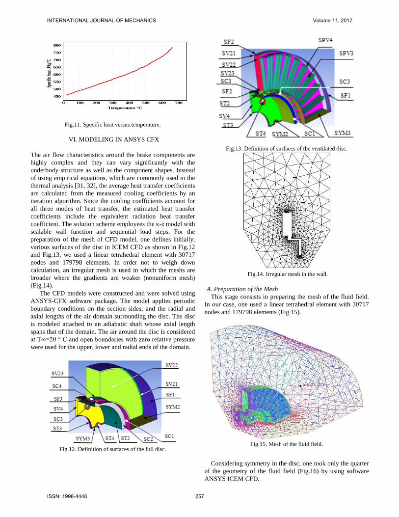
Fig.11. Specific heat versus temperature.
VI. MODELING IN ANSYS CFX
The air flow characteristics around the brake components are highly complex and they can vary significantly with the underbody structure as well as the component shapes. Instead of using empirical equations, which are commonly used in the thermal analysis [31, 32], the average heat transfer coefficients are calculated from the measured cooling coefficients by an iteration algorithm. Since the cooling coefficients account for all three modes of heat transfer, the estimated heat transfer coefficients include the equivalent radiation heat transfer coefficient. The solution scheme employees the κ-ε model with scalable wall function and sequential load steps. For the preparation of the mesh of CFD model, one defines initially, various surfaces of the disc in ICEM CFD as shown in Fig.12 and Fig.13; we used a linear tetrahedral element with 30717 nodes and 179798 elements. In order not to weigh down calculation, an irregular mesh is used in which the meshs are broader where the gradients are weaker (nonuniform mesh) (Fig.14).
The CFD models were constructed and were solved using ANSYS-CFX software package. The model applies periodic boundary conditions on the section sides; and the radial and axial lengths of the air domain surrounding the disc. The disc is modeled attached to an adiabatic shaft whose axial length spans that of the domain. The air around the disc is considered at T∞=20 ° C and open boundaries with zero relative pressure were used for the upper, lower and radial ends of the domain.
Fig.12. Definition of surfaces of the full disc.
Fig.13. Definition of surfaces of the ventilated disc.
Fig.14. Irregular mesh in the wall.
A. Preparation of the Mesh
This stage consists in preparing the mesh of the fluid field. In our case, one used a linear tetrahedral element with 30717 nodes and 179798 elements (Fig.15).
Fig.15. Mesh of the fluid field.
Considering symmetry in the disc, one took only the quarter of the geometry of the fluid field (Fig.16) by using software ANSYS ICEM CFD.
INTERNATIONAL JOURNAL OF MECHANICS Volume 11, 2017
ISSN: 1998-4448 257

Fig.16. Definition of surfaces of the fluid field. In this step, one declares all of the physical characteristics of the fluid and the solid. It was introduced into the library, the physical properties of materials used. In this study, we selected three gray cast iron materials (FG25AL, FG20, FG15) having a thermal conductiovity respectively ( 43.7 W/m°C , 55 W/m°C and 57 W/m°C). Since the aim of this study is to determine the temperature field in a disc brake during the braking phase of a vehicle of the average class, we take the following temporal conditions:
• Braking time = 3.5 [ s ] • Increment time = 0.01 [ s] • Initial time = 0 [ s]
The disc is attached to four adiabatic surfaces and two surfaces of symmetry in the fluid domain with an ambient air temperature of 20 ° C . Fig.17. shows the elaborated CFD model to be used in ANSYS cfx Pre.
Fig.17.Brake disc CFD model.
Fig.18. Distribution of heat transfer coefficient on a full disc
in the steady state case (FG 15).
The airflow through and around the brake disc was analyzed using the ANSYS CFX software package. The ANSYS-CFX solver automatically calculates heat transfer coefficient at the wall boundary .Afterwards the heat transfer coefficients considering convection were calculated and organized in such a way, that they could be used as a boundary condition in thermal analysis. Averaged heat transfer coefficient had to be calculated for all disc using ANSYS CFX Post as it is indicated in Figs.18-19-20 and 21. Table 3. Value of the heat transfer coefficient of different surfaces in
the stationary case for a full disc (FG 15).
FG 15 Surface hmoy= [W m-2 k-1]
SC1 25,29168 SC2 5,18003 SC3 2,922075 SC4 11,77396 SF1 111,20765 SF3 53,15547 ST2 23,22845 ST3 65,6994 ST4 44,26725 SV1 81,37535 SV2 71,75842 SV3 41,83303 SV4 65,82545
Fig.19. Distribution of heat-transfer coefficient on a
ventilated disc in the stationary case (FG 25 AL).
Air at 20 C°
Outlet
Disc
Input
Symmetric wall of the air
Adiabatic wall of the air
Interface Fluid-solid
Exit of the air
DSYM1
DR1 DV1
Entry 1 of the air
Entry 2 of the air
INTERNATIONAL JOURNAL OF MECHANICS Volume 11, 2017
ISSN: 1998-4448 258
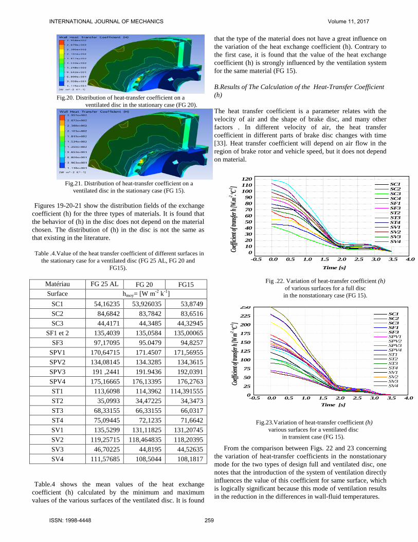
Fig.20. Distribution of heat-transfer coefficient on a
ventilated disc in the stationary case (FG 20).
Fig.21. Distribution of heat-transfer coefficient on a
ventilated disc in the stationary case (FG 15).
Figures 19-20-21 show the distribution fields of the exchange coefficient (h) for the three types of materials. It is found that the behavior of (h) in the disc does not depend on the material chosen. The distribution of (h) in the disc is not the same as that existing in the literature. Table .4.Value of the heat transfer coefficient of different surfaces in
the stationary case for a ventilated disc (FG 25 AL, FG 20 and FG15).
Matériau
FG 25 AL
FG 20 FG15 Surface hmoy= [W m-2 k-1]
SC1 54,16235 53,926035 53,8749 SC2 84,6842 83,7842 83,6516 SC3 44,4171 44,3485 44,32945
SF1 et 2 135,4039 135,0584 135,00065 SF3 97,17095 95.0479 94,8257
SPV1 170,64715 171.4507 171,56955 SPV2 134,08145 134.3285 134,3615 SPV3 191 ,2441 191.9436 192,0391 SPV4 175,16665 176,13395 176,2763 ST1 113,6098 114,3962 114,391555 ST2 35,0993 34,47225 34,3473 ST3 68,33155 66,33155 66,0317 ST4 75,09445 72,1235 71,6642 SV1 135,5299 131,11825 131,20745 SV2 119,25715 118,464835 118,20395 SV3 46,70225 44,8195 44,52635 SV4 111,57685 108,5044 108,1817
Table.4 shows the mean values of the heat exchange
coefficient (h) calculated by the minimum and maximum values of the various surfaces of the ventilated disc. It is found
that the type of the material does not have a great influence on the variation of the heat exchange coefficient (h). Contrary to the first case, it is found that the value of the heat exchange coefficient (h) is strongly influenced by the ventilation system for the same material (FG 15).
B.Results of The Calculation of the Heat-Transfer Coefficient (h) The heat transfer coefficient is a parameter relates with the velocity of air and the shape of brake disc, and many other factors . In different velocity of air, the heat transfer coefficient in different parts of brake disc changes with time [33]. Heat transfer coefficient will depend on air flow in the region of brake rotor and vehicle speed, but it does not depend on material.
-0.5 0.0 0.5 1.0 1.5 2.0 2.5 3.0 3.5 4.00
102030405060708090
100110120
SC1 SC2 SC3 SC4 SF1 SF3 ST2 ST3 ST4 SV1 SV2 SV3 SV4
Coeffi
cient o
f trans
fer h [
W.m-2 .°C
-1 ]
Time [s]
-0.5 0.0 0.5 1.0 1.5 2.0 2.5 3.0 3.5 4.00
25
50
75
100
125
150
175
200
225
250 SC1 SC2 SC3 SF1 SF3 SPV1 SPV2 SPV3 SPV4 ST1 ST2 ST3 ST4 SV1 SV2 SV3 SV4Coe
fficien
t of tra
nsfer h
[W m-2 °C
-1 ]
Time [s]
From the comparison between Figs. 22 and 23 concerning
the variation of heat-transfer coefficients in the nonstationary mode for the two types of design full and ventilated disc, one notes that the introduction of the system of ventilation directly influences the value of this coefficient for same surface, which is logically significant because this mode of ventilation results in the reduction in the differences in wall-fluid temperatures.
Fig.23.Variation of heat-transfer coefficient (h) various surfaces for a ventilated disc
in transient case (FG 15).
Fig .22. Variation of heat-transfer coefficient (h) of various surfaces for a full disc in the nonstationary case (FG 15).
INTERNATIONAL JOURNAL OF MECHANICS Volume 11, 2017
ISSN: 1998-4448 259
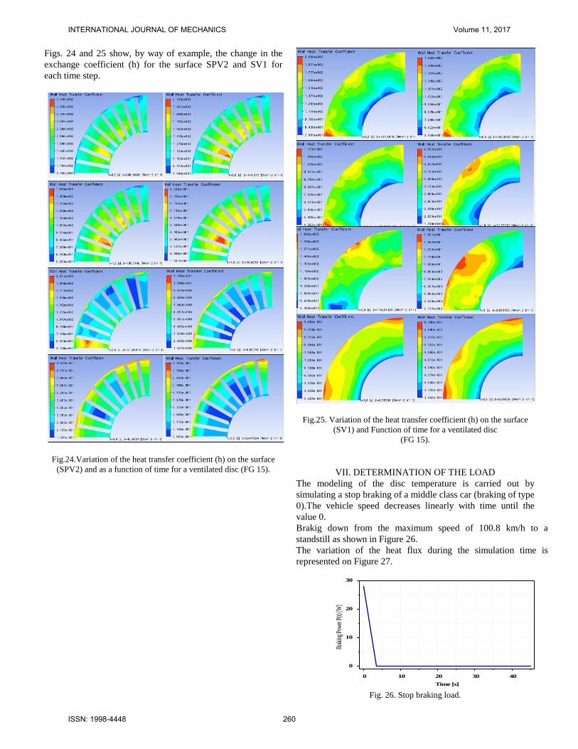
Figs. 24 and 25 show, by way of example, the change in the exchange coefficient (h) for the surface SPV2 and SV1 for each time step.
Fig.24.Variation of the heat transfer coefficient (h) on the surface (SPV2) and as a function of time for a ventilated disc (FG 15).
Fig.25. Variation of the heat transfer coefficient (h) on the surface (SV1) and Function of time for a ventilated disc
(FG 15).
VII. DETERMINATION OF THE LOAD The modeling of the disc temperature is carried out by simulating a stop braking of a middle class car (braking of type 0).The vehicle speed decreases linearly with time until the value 0. Brakig down from the maximum speed of 100.8 km/h to a standstill as shown in Figure 26. The variation of the heat flux during the simulation time is represented on Figure 27.
0 10 20 30 40
0
10
20
30
Braki
ng Pow
er P(t)
[W]
Time [s]
Fig. 26. Stop braking load.
INTERNATIONAL JOURNAL OF MECHANICS Volume 11, 2017
ISSN: 1998-4448 260
0 10 20 30 400
1x10⁶
2x10⁶
3x10⁶
4x10⁶
5x10⁶
Heat F
lux [W
m-2 ]
Time [s]
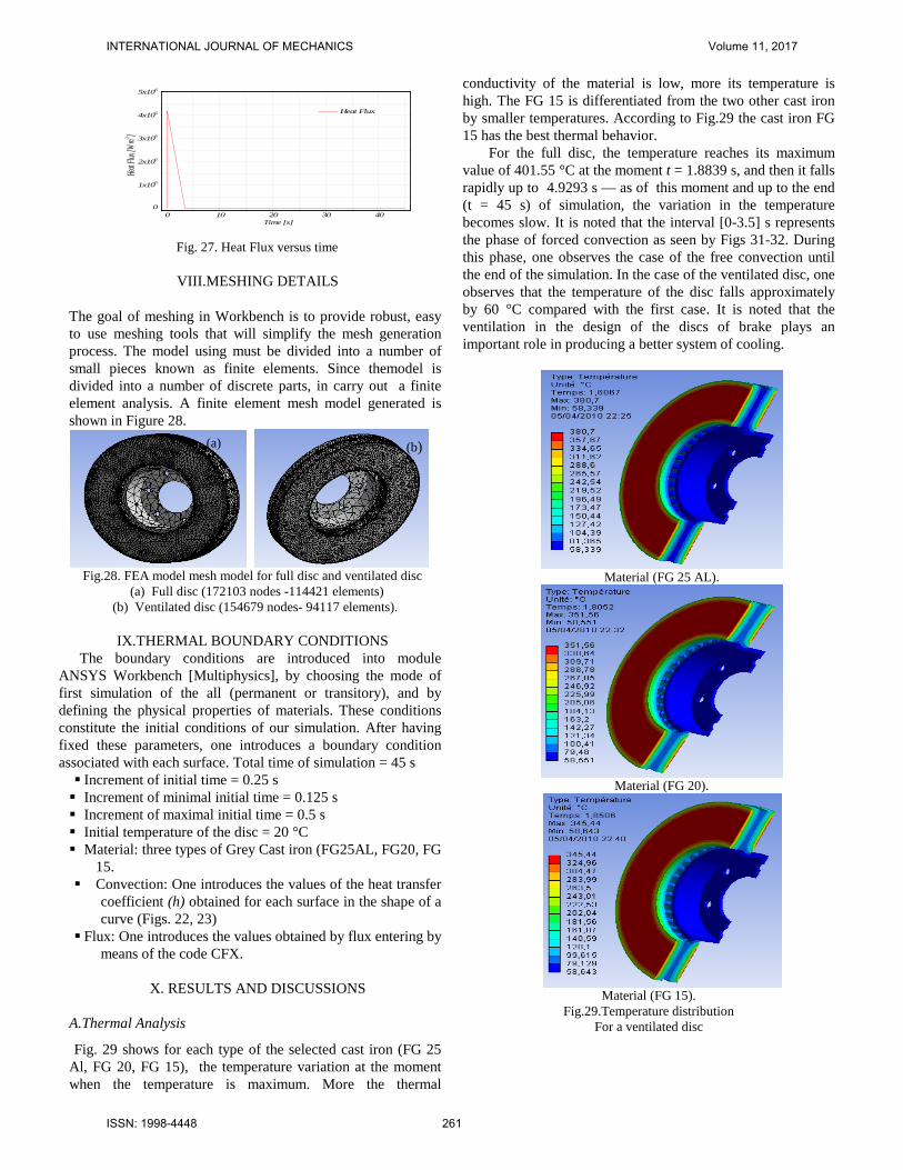
Heat Flux
Fig. 27. Heat Flux versus time
VIII.MESHING DETAILS
The goal of meshing in Workbench is to provide robust, easy to use meshing tools that will simplify the mesh generation process. The model using must be divided into a number of small pieces known as finite elements. Since themodel is divided into a number of discrete parts, in carry out a finite element analysis. A finite element mesh model generated is shown in Figure 28.
Fig.28. FEA model mesh model for full disc and ventilated disc
(a) Full disc (172103 nodes -114421 elements) (b) Ventilated disc (154679 nodes- 94117 elements).
IX.THERMAL BOUNDARY CONDITIONS
The boundary conditions are introduced into module ANSYS Workbench [Multiphysics], by choosing the mode of first simulation of the all (permanent or transitory), and by defining the physical properties of materials. These conditions constitute the initial conditions of our simulation. After having fixed these parameters, one introduces a boundary condition associated with each surface. Total time of simulation = 45 s Increment of initial time = 0.25 s Increment of minimal initial time = 0.125 s Increment of maximal initial time = 0.5 s Initial temperature of the disc = 20 °C Material: three types of Grey Cast iron (FG25AL, FG20, FG
15. Convection: One introduces the values of the heat transfer
coefficient (h) obtained for each surface in the shape of a curve (Figs. 22, 23)
Flux: One introduces the values obtained by flux entering by means of the code CFX.
X. RESULTS AND DISCUSSIONS
A.Thermal Analysis
Fig. 29 shows for each type of the selected cast iron (FG 25 Al, FG 20, FG 15), the temperature variation at the moment when the temperature is maximum. More the thermal
conductivity of the material is low, more its temperature is high. The FG 15 is differentiated from the two other cast iron by smaller temperatures. According to Fig.29 the cast iron FG 15 has the best thermal behavior.
For the full disc, the temperature reaches its maximum value of 401.55 °C at the moment t = 1.8839 s, and then it falls rapidly up to 4.9293 s — as of this moment and up to the end (t = 45 s) of simulation, the variation in the temperature becomes slow. It is noted that the interval [0-3.5] s represents the phase of forced convection as seen by Figs 31-32. During this phase, one observes the case of the free convection until the end of the simulation. In the case of the ventilated disc, one observes that the temperature of the disc falls approximately by 60 °C compared with the first case. It is noted that the ventilation in the design of the discs of brake plays an important role in producing a better system of cooling.
Material (FG 25 AL).
Material (FG 20).
Material (FG 15).
Fig.29.Temperature distribution For a ventilated disc
(b) (a)
INTERNATIONAL JOURNAL OF MECHANICS Volume 11, 2017
ISSN: 1998-4448 261

Fig.30. Temperature distribution of a full (a) and ventilated disc (b)
of cast iron (FG 15).
Fig. 31. Variation of temperature of the full disc
of the time (FG 15).
Fig. 32. Variation of temperature of the ventilated disc
of the time (FG 15).
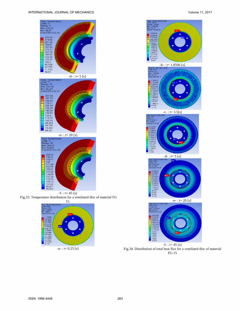
B. Temperature and Heat Flux Distribution in Ventilated Disc
In this part, one presents the cartographies of total and directional heat flux and as well as the temperature distribution in a ventilated disc and of cast iron FG 15 for each moment with braking as indicated in Figure 33. The temperature distribution of the disc at the beginning of braking
(with t=0.25 s) is inhomogenous. According to experimental tests' carried out by research , braking often begin with the formation from hot circles relatively on the uniform surfaces of the disc in the circumferential direction, moving radially on the disc and transforming then into hot points ((hot spot)).The appearance of the phenomenon of the hot points is due to the nonuniform dissipation of heat flux.
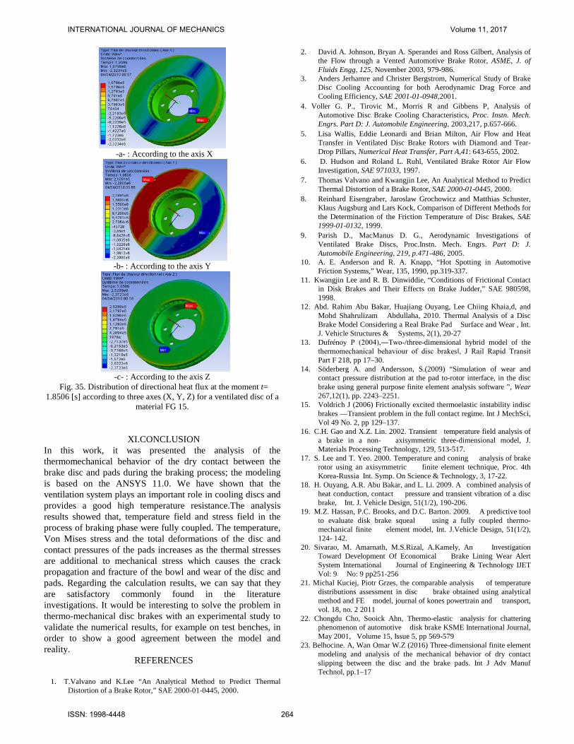
Concerning the heat flux, one notes according to figures 34 and 35 that the maximum value of the total heat flux is located on the level of the calorific throat at the end of braking (t=3,5 s);this is explained by the increase in the gradients and the thermal concentrations in this zone. The calorific throat is manufactured so as to limit the heat flux coming from the friction tracks and moving towards the bowl of the disc brake in order to avoid the excessive heating of the rim and the tire. During the heating, the disc is tightened to dilate in the hot zones from where creating of compressive stresses with plasticization. On the other hand, during cooling, there is appearance of residual stresses of traction. The disc is thus subjected during its rotation to constraints traction/compression.
-a - : t= 0.25 [s]
-b- : t= 1.8506 [s]
-c- : t= 3.5 [s]
(a)
(b)
INTERNATIONAL JOURNAL OF MECHANICS Volume 11, 2017
ISSN: 1998-4448 262
-d- : t= 5 [s]
-e- : t= 20 [s]
-f- : t= 45 [s]
Fig.33. Temperature distribution for a ventilated disc of material FG 15.
-a- : t= 0.25 [s]
-b- : t= 1.8506 [s]
-c- : t= 3.5[s]
-d- : t= 5 [s]
-e- : t= 20 [s]
-f- : t= 45 [s]
Fig.34. Distribution of total heat flux for a ventilated disc of material FG 15
INTERNATIONAL JOURNAL OF MECHANICS Volume 11, 2017
ISSN: 1998-4448 263
-a- : According to the axis X
-b- : According to the axis Y
-c- : According to the axis Z
Fig. 35. Distribution of directional heat flux at the moment t= 1.8506 [s] according to three axes (X, Y, Z) for a ventilated disc of a
material FG 15.
XI.CONCLUSION In this work, it was presented the analysis of the thermomechanical behavior of the dry contact between the brake disc and pads during the braking process; the modeling is based on the ANSYS 11.0. We have shown that the ventilation system plays an important role in cooling discs and provides a good high temperature resistance.The analysis results showed that, temperature field and stress field in the process of braking phase were fully coupled. The temperature, Von Mises stress and the total deformations of the disc and contact pressures of the pads increases as the thermal stresses are additional to mechanical stress which causes the crack propagation and fracture of the bowl and wear of the disc and pads. Regarding the calculation results, we can say that they are satisfactory commonly found in the literature investigations. It would be interesting to solve the problem in thermo-mechanical disc brakes with an experimental study to validate the numerical results, for example on test benches, in order to show a good agreement between the model and reality.
REFERENCES
1. T.Valvano and K.Lee “An Analytical Method to Predict Thermal Distortion of a Brake Rotor,” SAE 2000-01-0445, 2000.
2. David A. Johnson, Bryan A. Sperandei and Ross Gilbert, Analysis of the Flow through a Vented Automotive Brake Rotor, ASME, J. of Fluids Engg, 125, November 2003, 979-986.
3. Anders Jerhamre and Christer Bergstrom, Numerical Study of Brake Disc Cooling Accounting for both Aerodynamic Drag Force and Cooling Efficiency, SAE 2001-01-0948,2001.
4. Voller G. P., Tirovic M., Morris R and Gibbens P, Analysis of Automotive Disc Brake Cooling Characteristics, Proc. Instn. Mech. Engrs. Part D: J. Automobile Engineering, 2003,217, p.657-666.
5. Lisa Wallis, Eddie Leonardi and Brian Milton, Air Flow and Heat Transfer in Ventilated Disc Brake Rotors with Diamond and Tear-Drop Pillars, Numerical Heat Transfer, Part A,41: 643-655, 2002.
6. D. Hudson and Roland L. Ruhl, Ventilated Brake Rotor Air Flow Investigation, SAE 971033, 1997.
7. Thomas Valvano and Kwangjin Lee, An Analytical Method to Predict Thermal Distortion of a Brake Rotor, SAE 2000-01-0445, 2000.
8. Reinhard Eisengraber, Jaroslaw Grochowicz and Matthias Schuster, Klaus Augsburg and Lars Kock, Comparison of Different Methods for the Determination of the Friction Temperature of Disc Brakes, SAE 1999-01-0132, 1999.
9. Parish D., MacManus D. G., Aerodynamic Investigations of Ventilated Brake Discs, Proc.Instn. Mech. Engrs. Part D: J. Automobile Engineering, 219, p.471-486, 2005.
10. A. E. Anderson and R. A. Knapp, “Hot Spotting in Automotive Friction Systems,” Wear, 135, 1990, pp.319-337.
11. Kwangjin Lee and R. B. Dinwiddie, “Conditions of Frictional Contact in Disk Brakes and Their Effects on Brake Judder,” SAE 980598, 1998.
12. Abd. Rahim Abu Bakar, Huajiang Ouyang, Lee Chiing Khaia,d, and Mohd Shahrulizam Abdullaha, 2010. Thermal Analysis of a Disc Brake Model Considering a Real Brake Pad Surface and Wear , Int. J. Vehicle Structures & Systems, 2(1), 20-27
13. Dufrénoy P (2004),―Two-/three-dimensional hybrid model of the thermomechanical behaviour of disc brakes‖, J Rail Rapid Transit Part F 218, pp 17–30.
14. Söderberg A. and Andersson, S.(2009) “Simulation of wear and contact pressure distribution at the pad to-rotor interface, in the disc brake using general purpose finite element analysis software ”, Wear 267,12(1), pp. 2243–2251.
15. Voldrich J (2006) Frictionally excited thermoelastic instability indisc brakes —Transient problem in the full contact regime. Int J MechSci, Vol 49 No. 2, pp 129–137.
16. C.H. Gao and X.Z. Lin. 2002. Transient temperature field analysis of a brake in a non- axisymmetric three-dimensional model, J. Materials Processing Technology, 129, 513-517.
17. S. Lee and T. Yeo. 2000. Temperature and coning analysis of brake rotor using an axisymmetric finite element technique, Proc. 4th Korea-Russia Int. Symp. On Science & Technology, 3, 17-22.
18. H. Ouyang, A.R. Abu Bakar, and L. Li. 2009. A combined analysis of heat conduction, contact pressure and transient vibration of a disc brake, Int. J. Vehicle Design, 51(1/2), 190-206.
19. M.Z. Hassan, P.C. Brooks, and D.C. Barton. 2009. A predictive tool to evaluate disk brake squeal using a fully coupled thermo-mechanical finite element model, Int. J.Vehicle Design, 51(1/2), 124- 142.
20. Sivarao, M. Amarnath, M.S.Rizal, A.Kamely, An Investigation Toward Development Of Economical Brake Lining Wear Alert System International Journal of Engineering & Technology IJET Vol: 9 No: 9 pp251-256
21. Michal Kuciej, Piotr Grzes, the comparable analysis of temperature distributions assessment in disc brake obtained using analytical method and FE model, journal of kones powertrain and transport, vol. 18, no. 2 2011
22. Chongdu Cho, Sooick Ahn, Thermo-elastic analysis for chattering phenomenon of automotive disk brake KSME International Journal, May 2001, Volume 15, Issue 5, pp 569-579
23. Belhocine. A, Wan Omar W.Z (2016) Three-dimensional finite element modeling and analysis of the mechanical behavior of dry contact slipping between the disc and the brake pads. Int J Adv Manuf Technol, pp.1–17
INTERNATIONAL JOURNAL OF MECHANICS Volume 11, 2017
ISSN: 1998-4448 264
24. Belhocine. A (2016) FE prediction of thermal performance and stresses in an automotive disc brake system. Int J Adv Manuf Technol, pp.1–16
25. Lele Zhang, Qiang Yang, D. Weichert , Nanlin Tan. Simulation and Analysis of Thermal Fatigue Based on Imperfection Model of Brake Discs, Beijing Jiaotong University, PAMM · Proc. Appl. Math. Mech. 9, 533 – 534 (2009)
26. J. Reimpel, Braking technology. Vogel Verlag, Würzburg, (1998). 27. Cruceanu, C., Frâne pentru vehicle feroviare (Brakes for railway
vehicles), Ed. MATRIXROM, Bucureşti, 2007, ISBN 978-973-755-200-6, 388 pag.
28. Gotowicki, Pier Francesco; Nigrelli, Vinzenco; Mariotti, Gabriele Virzi. Numerical and experimental analysis of a pegs- wing ventilated disk brake rotor, with pads and cylinders, 10 th EAEC Eur.Automot. Cong – Paper EAEC05YUAS04– P 5, June (2005).
29. M. K. Khalid, M. R. Mansor, S. I. Abdul Kudus, M. M. Tahir, and M. Z. Hassan, Performance Investigation of the UTeM Eco- Car Disc Brake System International Journal of Engineering & Technology IJET-IJENS Vol: 11 No: 06 pp-1-6
30. R.Limpert, Brake Design and Safety. 2nd Edition, Warrendale,Pennsylvania: Society of Automotive Engineering Inc., 1999, pp. 137-144.
31. H. Dittrich and R. Lang, “Finite-Element Analysis of the Thermal Loads Acting on a Passenger Car Brake Disk,” Automobiltechnische Zeitschrift, Vol. 86, No. 6, pp. 265-269, 1984.
32. A. Fukano and H. Matsui, “Development of Disc- Brake Design Method Using Computer Simulation of Heat Phenomena,” SAE 860634, 1986.
33. Zhang, J.,Xia,C.(2012).Research of the TransientTemperatureField and Friction Properties on Disc Brakes, Proceedings of the 2012 2nd International Conference on Computer and Information Application (ICCIA 2012) 201-204.
A. Belhocine received his Magister degree in Mechanical Engineering in 2006 from Mascara University, Mascara, Algeria. After then, he was a PhD student at the University of Science and the Technology of Oran (USTO Oran), Algeria. He has recently obtained his Ph.D. degrees in Mechanical Engineering at the same University. His research interests include Automotive Braking Systems, Finite Element Method (FEM), ANSYS simulation, CFD Analysis, Heat Transfer, Thermal-Structural Analysis, Tribology and Contact Mechanic. W.Z.Wan Omar is senior lecturer at the Faculty of Mechanical Engineering, Universiti Teknologi Malaysia, 81310 UTM Skudai, Malaysia .
INTERNATIONAL JOURNAL OF MECHANICS Volume 11, 2017
ISSN: 1998-4448 265