bs-14 - television broadcast videotex - ic
TRANSCRIPT

BS-14Issue 1ProvisionalJune 19, 1981
Spectrum Management
Broadcasting Specification
Television Broadcast Videotex

Television Broadcast Videotex BS-14
Definition
Television Broadcast Videotex: A system consisting of a central data store (database) fromwhich digital data representing text and pictorialinformation is transmitted in the active portion ofavailable TV lines through a broadcast delivery system.User terminals then interpret and display the selecteddata on video receivers/monitors or other terminal devices.
Introduction
The parameters outlined in this document have been selected intending to complywith the following principles and requirements:
(i) Terminal independence; this permits the use of a variety of terminals of varyingcapabilities, such as different levels of resolution.
(ii) Compatibility between services carried over existing communications networks(e.g., public switched telephone, off-air broadcast, satellite and cable TVnetworks.) and common presentation format.
(iii) Vertical blanking interval (VBI) and full field transmission compatibility.
(iv) Forward and backward compatibility; permitting future terminals to access olddata and requiring that an installed inventory of terminals be able to receive anddecode all future command formats in an intelligent manner.
(v) Adherence to already established national and international standards such asthose contained in Appendix A.
Applicability
This document sets forth the requirements for the issuance of a TechnicalConstruction and Operating Certificate (TC & OC) for a broadcasting transmittingundertaking when transmitting digitally encoded data for purposes includingalphanumeric and/or pictorial information. The requirements also apply to a broadcastingreceiving undertaking when the distributed signals are received from a broadcastingtransmitting undertaking.
1

Television Broadcast Videotex BS-14
1. Data Positioning and Waveforms
Data may be transmitted in the active portion of a television line, commencing afterthe standard NTSC line synchronization and colour burst.
1.1 Vertical Blanking Interval and Full-Field Data Transmission
Data transmission uses the field-blanking interval and/or the active part of thevideo signal. Lines 1 through 21 in field 1 and the corresponding lines in field 2of the 525 line 60 field/sec M/NTSC television system are designated as thevertical blanking interval (VBI). Of these, the allocation of lines 10 through 21 infield 1 and the corresponding lines in field 2 is the subject of BroadcastSpecification 13. Full-field data transmission is achieved through utilization oflines 10 through 262 in field 1 and the corresponding lines in field 2 whichcomprises the vertical blanking interval as well as the active part.
1.2 Transmission Bit Rate
The transmission bit rate is 5,727,272 + 16 bits/second* which is the 364thmultiple of the horizontal line scanning rate for colour transmission(15,734.264 + .044 Hz) and 8/5 of the colour sub-carrier frequency(3,579,545 + 10 Hz). The data signal is to be phased locked to the coloursub-carrier when inserted into a colour television transmission and to thehorizontal line scanning rate when inserted into a monochrome televisiontransmission (with no burst present). The maximum rate of changebits/second/second.
*Note: The adoption of the proposed bit rate of 5,727,272 + 16 bits/sec will onlybe finalized following a period of adequate experimentation. Should it bedetermined that the proposed bit rate is unsatisfactory in providingadequate service, an alternate bit rate would be considered. This actionwould therefore necessitate the revision of related parameters aspresented in this provisional document.
2
Television Broadcast Videotex BS-14
1.3 Data Encoding
The amplitude modulated data is non-return to zero (NRZ) binary encoded. Otherencoding schemes are for further study.
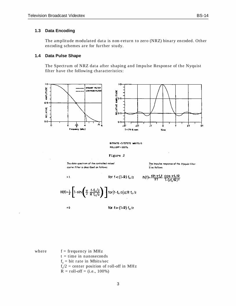
1.4 Data Pulse Shape
The Spectrum of NRZ data after shaping and Impulse Response of the Nyquistfilter have the following characteristics:
where f = frequency in MHzt = time in nanosecondsfo = bit rate in Mbits/secfo/2 = center position of roll-off in MHzR = roll-off = (i.e., 100%)
3
Television Broadcast Videotex BS-14
The spectral content of the shaped data is determined by a Nyquist filter with100% roll-off, followed by a phase corrected low-pass filter with a cut off of4.2 MHz.
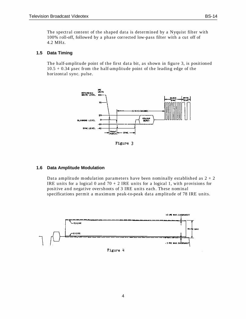
1.5 Data Timing
The half-amplitude point of the first data bit, as shown in figure 3, is positioned10.5 + 0.34 µsec from the half-amplitude point of the leading edge of thehorizontal sync. pulse.
1.6 Data Amplitude Modulation
Data amplitude modulation parameters have been nominally established as 2 + 2IRE units for a logical 0 and 70 + 2 IRE units for a logical 1, with provisions forpositive and negative overshoots of 3 IRE units each. These nominalspecifications permit a maximum peak-to-peak data amplitude of 78 IRE units.
4
Television Broadcast Videotex BS-14
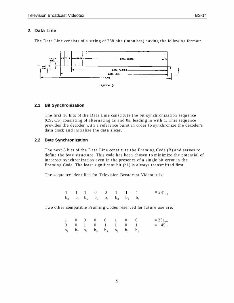
2. Data Line
The Data Line consists of a string of 288 bits (impulses) having the following format:
2.1 Bit Synchronization
The first 16 bits of the Data Line constitute the bit synchronization sequence(CS, CS) consisting of alternating 1s and 0s, leading in with 1. This sequenceprovides the decoder with a reference burst in order to synchronize the decoder'sdata clock and initialize the data slicer.
2.2 Byte Synchronization
The next 8 bits of the Data Line constitute the Framing Code (B) and serves todefine the byte structure. This code has been chosen to minimize the potential ofincorrect synchronization even in the presence of a single bit error in theFraming Code. The least significant bit (b1) is always transmitted first.
The sequence identified for Television Broadcast Videotex is:
1b8
1b7
1b6
0b5
0b4
1b3
1b2
1b1
≡ 23110
Two other compatible Framing Codes reserved for future use are:
10b8
00b7
01b6
00b5
01b4
11b3
00b2
01b1
≡ 23110
≡ 4510
5

Television Broadcast Videotex BS-14
3. Data Packet
The Data Packet is an identifiable package transmitted after the Bit and ByteSynchronization codes and is made up of: a Prefix, a Data Block and an optionalSuffix.
A Data Packet is contained within a single Data Line. Extended Packets,encompassing more than one Data Line, are for further study.
3.1 Prefix
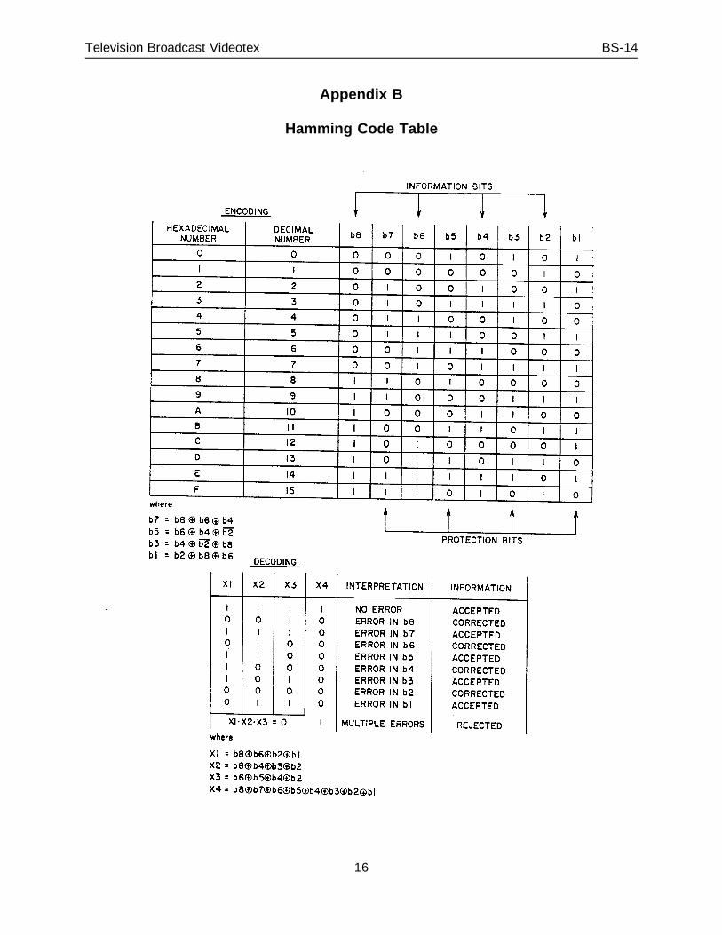
The Prefix consists of 5 Hamming*-encoded bytes, the first 3 of which are PacketAddress bytes followed by a Continuity Index byte (CI) and a Packet Structurebyte (PS).
* In this document, an (8,4) Hamming data protection scheme is used, thuspermitting single bit error correction, and even multiple bit error detection. Inany Hamming-protected byte, bits b1, b3, b5 and b7 provide error protectionand bits b2, b4, b6 and b8 present the information to be conveyed. Appendix Bprovides the Haming Code Table.
3.1.1 Packet Address
Three Hamming-encoded bytes (P1, P2, P3) constitute the Packet Address,yielding 212 (4096) possible data channels which may be time-divisionmultiplexed onto a single television channel. Channel numbers corresponddirectly to Decimal Binary Coding permitting user selection of the first
6
Television Broadcast Videotex BS-14
1000 channels using a simple decimal keypad. The remaining channelsare reserved for future use.
The scheme allows for interleaving of combinations of up to fourconsecutive data lines, with one Packet Address, with Data Lines of otherPacket Addresses and requires a minimum time separation of4 milliseconds for both VBI and full-field operation.
3.1.2 Continuity Index
The Continuity Index consists of one Hamming-protected byte (CI) used todetect the loss of a Data Packet due to transmission errors. TheContinuity Index sequences from 0 to 15 and is incremented by 1 for eachtransmission of a Data Packet within a Data Channel.
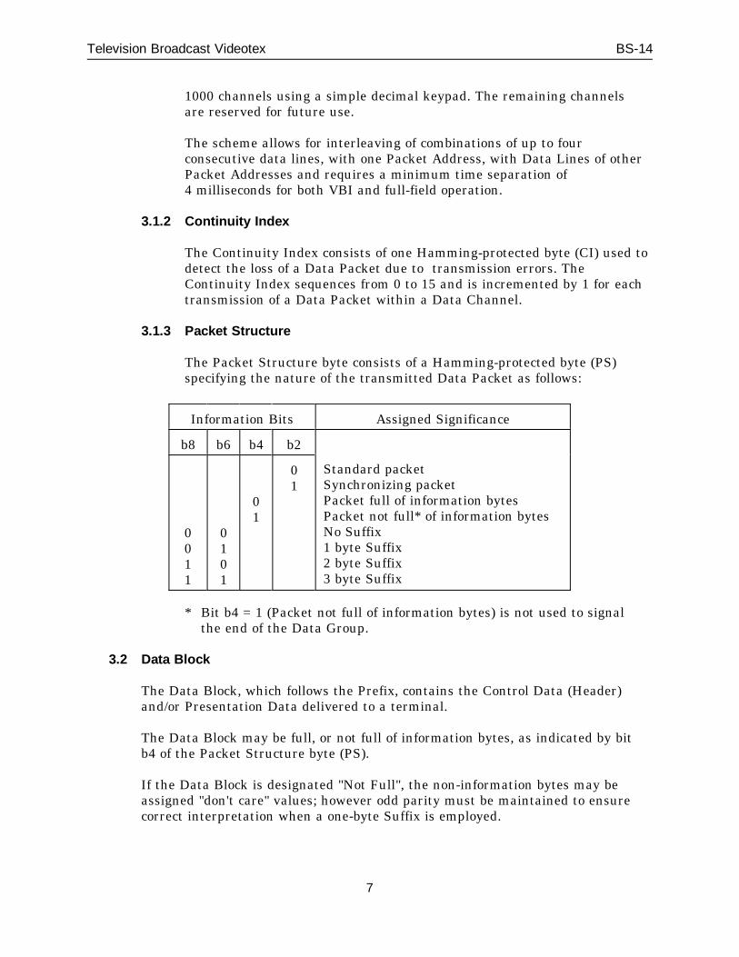
3.1.3 Packet Structure
The Packet Structure byte consists of a Hamming-protected byte (PS)specifying the nature of the transmitted Data Packet as follows:
Information Bits Assigned Significance
b8 b6 b4 b2
0011
0101
01
01
Standard packetSynchronizing packetPacket full of information bytesPacket not full* of information bytesNo Suffix1 byte Suffix2 byte Suffix3 byte Suffix
* Bit b4 = 1 (Packet not full of information bytes) is not used to signalthe end of the Data Group.
3.2 Data Block
The Data Block, which follows the Prefix, contains the Control Data (Header)and/or Presentation Data delivered to a terminal.
The Data Block may be full, or not full of information bytes, as indicated by bitb4 of the Packet Structure byte (PS).
If the Data Block is designated "Not Full", the non-information bytes may beassigned "don't care" values; however odd parity must be maintained to ensurecorrect interpretation when a one-byte Suffix is employed.
7
Television Broadcast Videotex BS-14
The Data Block is reduced by the number of Suffix bytes as specified by bits b8,b6 of the Packet Structure byte:
no Suffix byte; the Data Block contains 28 bytes,1 Suffix byte; the Data Block contains 27 bytes,2 Suffix bytes; the Data Block contains 26 bytes,3 Suffix bytes; the Data Block contains 25 bytes.
3.2.1 Control Data (Header)
The Header consists of information bytes used in instructing the terminalin processing Presentation Data.
3.2.2 Presentation Data
The Presentation Data is comprised of the data to be processed by theuser terminal.
3.3 Suffix
An optional Suffix may follow the Data Block as determined by bits b8, b6 of thePacket Structure byte. This Suffix may contain one or more redundancy byteswhich may be used by the data receiver for either error detection or correction inthe Data Block.
A single byte Suffix is comprised of a longitudinal odd parity check of all bytes inthe Data Block, which themselves contain an odd parity check in the mostsignificant bit (b8) of each byte. This information forms the basis of the productcode used to correct any single bit error and detect all double errors in each byte.
Other error detection/correction schemes for double or triple byte Suffixes arereserved for future assignments.
4. Data Group
Data Blocks associated with information from the same source (i.e., common PacketAddress bytes: P1, P2, P3) may be sequentially organized into identifiable groupsknown as Data Groups. In broadcast videotex, these Data Groups are limited in lengthto a maximum of two (2) kilobytes.
The beginning of a Data Group is identified by bit b2=1 of the Packet Structure byte(PS). Each Data Group is composed of a Data Group Header followed by a Record.
8
Television Broadcast Videotex BS-14
4.1 Data Group Header
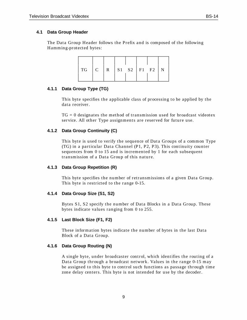
The Data Group Header follows the Prefix and is composed of the followingHamming-protected bytes:
TG C R S1 S2 F1 F2 N
4.1.1 Data Group Type (TG)
This byte specifies the applicable class of processing to be applied by thedata receiver.
TG = 0 designates the method of transmission used for broadcast videotexservice. All other Type assignments are reserved for future use.
4.1.2 Data Group Continuity (C)
This byte is used to verify the sequence of Data Groups of a common Type(TG) in a particular Data Channel (P1, P2, P3). This continuity countersequences from 0 to 15 and is incremented by 1 for each subsequenttransmission of a Data Group of this nature.
4.1.3 Data Group Repetition (R)
This byte specifies the number of retransmissions of a given Data Group.This byte is restricted to the range 0-15.
4.1.4 Data Group Size (S1, S2)
Bytes S1, S2 specify the number of Data Blocks in a Data Group. Thesebytes indicate values ranging from 0 to 255.
4.1.5 Last Block Size (F1, F2)
These information bytes indicate the number of bytes in the last DataBlock of a Data Group.
4.1.6 Data Group Routing (N)
A single byte, under broadcaster control, which identifies the routing of aData Group through a broadcast network. Values in the range 0-15 maybe assigned to this byte to control such functions as passage through timezone delay centers. This byte is not intended for use by the decoder.
9
Television Broadcast Videotex BS-14
5. Record
The Record is essentially the same as the Data Group stripped off the Data GroupHeader and contains information pertinent to broadcast videotex service. Each Recordis comprised of a series of up to 256 sequentially-numbered Data Blocks. The formatconsists of a Record Header, containing Record protocol information, followed byPresentation Data.
5.1 Record Header
The Record Header immediately follows the Data Group Header and is ofvariable length as determined by the Record Header Designator (RHD) andaddition of optional subgroups. (Refer to Appendix C)
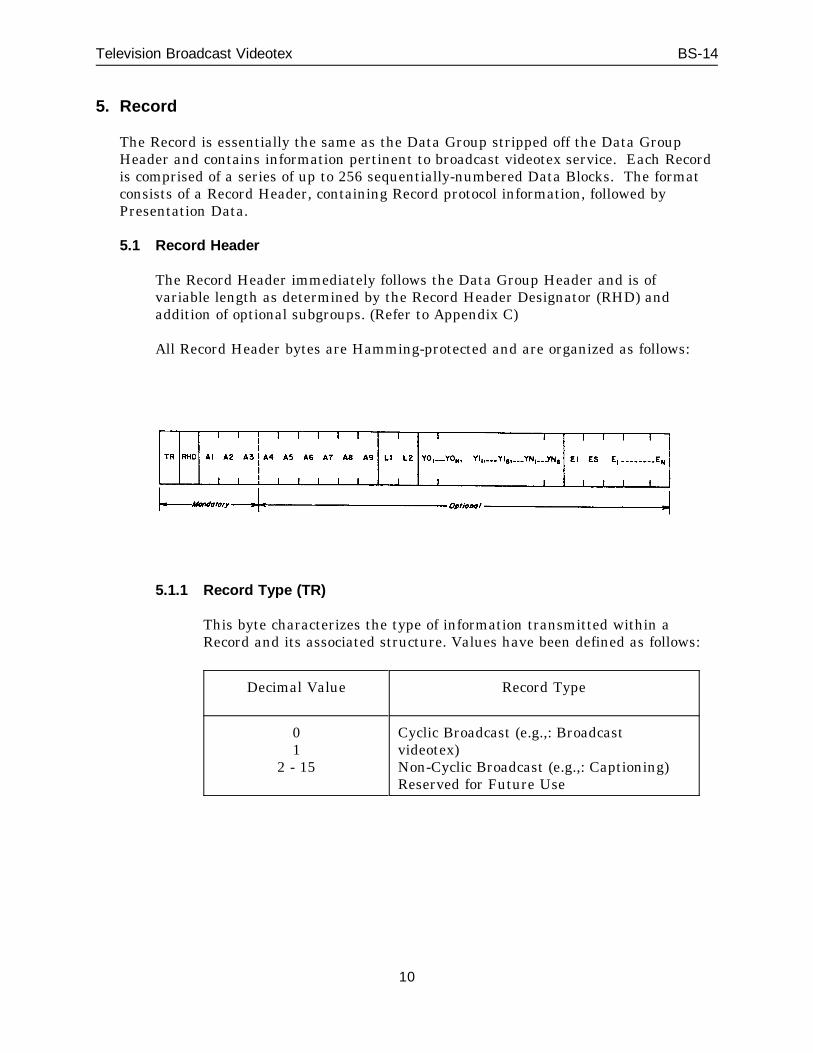
All Record Header bytes are Hamming-protected and are organized as follows:
5.1.1 Record Type (TR)
This byte characterizes the type of information transmitted within aRecord and its associated structure. Values have been defined as follows:
Decimal Value Record Type
01
2 - 15
Cyclic Broadcast (e.g.,: Broadcastvideotex)Non-Cyclic Broadcast (e.g.,: Captioning)Reserved for Future Use
10
Television Broadcast Videotex BS-14
5.1.2 Record Header Designator (RHD)
The Record Header Designator byte (RHD) is comprised of four flagswhich, when set, indicate the presence of one or more following subgroupswhich are concatenated in the following order:
b2: Address Extensionb4: Record Linkingb6: Complementary Record Classificationb8: Header Extension Field
The status of each of the above subgroups is indicated by a single bit,where a binary 1 indicates the presence of the subgroup, and a binary 0indicates its absence.
5.1.3 Address Bytes (A1, A2, A3, A4, A5, A6, A7, A8, A9)
Address bytes A1, A2, A3 represent a Record or Page number, and areconsidered mandatory. Address bytes A4, A5, A6, A7, A8, A9 are optionalextension bytes which are transmitted when bit b2 of the Record HeaderDesignator is set to 1. In this case, bytes A1-A7 are used to represent aDocument number and bytes A8, A9 represent the number of a Pagewithin a Document.
5.1.4 Record Linking (L1, L2)
The presence of the Record Linking bytes L1, L2 is indicated by bit b4 = 1in the Record Header Designator. These bytes immediately follow theAddress bytes. These bytes are used to link together Records identified bythe same address and associated with the same message. The decodermust capture linked Records in sequential order.
Bits b6, b4 and b2 of byte L1 and b8, b6, b4 and b2 of byte 12 are used toindicate the order of the linked Records. Bit b8 of L1 is used to indicatethe existence of additional linked Records (b8 = 1) or the last linkedRecord in the sequence (b8 = 0).
5.1.5 Complementary Classification Sequence (Y0 1-Y0N, Y11-Y16 ...YN1-YN6)
The presence of the Complementary Classification Sequence subgroup isindicated by bit b6 = 1 in the Record Header Designator. This subgroupfollows the Address and Link bytes, if present, or the Record HeaderDesignator. This subgroup follows the Address and Link bytes, if present,or the Record Header Designator for the case b2 = b4 = 0.
11
Television Broadcast Videotex BS-14
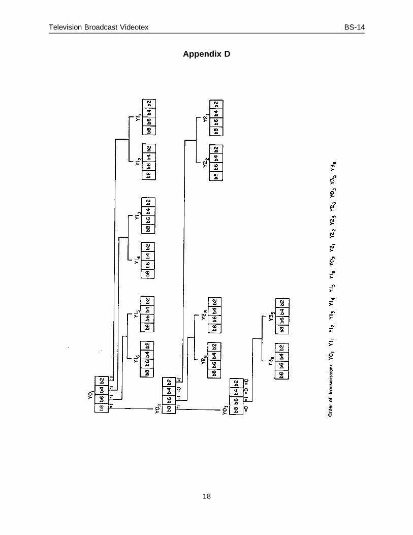
This subgroup has a variable format and is divided into two sections:(refer to Appendix D.)
- Designation bytes (Y01 - Y0N)
- Complementary Classification bytes (Y11-Y16, ...YN1-YN6)
Bit b8 of any Y0 byte indicates the status of any additional Designationbytes, where a binary 1 indicates the presence of an additional Y0 byte,and a binary 0 indicates the end of a Y0 sequence. For example, if bit b8of Y01 is equal to 1 an additional Y0 byte designated Y02 exists. Thispattern also applies to Y02 which in turn may indicate a Y03 byte, etc. TheY0 sequence is only terminated when bit b8 of the last Y0 byte is equal to0. This scheme is illustrated in Appendix D.
The remaining usable bits (b6, b4, b2) of any Y0 byte point to a group ofClassification bytes; (refer to Appendix E). Each bit of a Y0 Designationbyte is associated with a Classification field, either specifying a functionby default (bx - 0) or calling a function (bx = 1) and thus specifying it witha two-byte sequence.
When Y0 has bits b8 = b6 = b4 = b2 = 0, it is the end of the RecordHeader and all Record specification functions are specified by default.
5.1.6 Header Extension Field (EI, ES)
Any number of variable-length Header Extension Fields may bedesignated by b8 = 1 of the Record Header Designator (RHD) byte (seeAppendix C). These fields directly follow the Address, Link andComplementary Classification bytes, if present, or the Record HeaderDesignator for the case b6 = b4 = b2 = 0.
The first byte of the Header Extension Field is an extension fieldintroducer byte (EI), with bit designations as follows:
b8 = 1 indicates further Header Extension Field(s) to follow (E1 ... EN)
= 0 indicates last Extension Field
b6, b4, b2 indicates Header Extension Code assignments whose valuesare given in Appendix E.
The second byte (ES) of the Header Extension Field indicates the numberof bytes of Extension Field information in the current Extension Field.
5.2 Segmentation
The Data Record may be segmented by the use of a Segmentation IdentificationSequence which consists of a three-byte sequence; the first byte of which is aspecific code corresponding to the "US" (unit separator) code taken from the C0
12
Television Broadcast Videotex BS-14
code table at the presentation level. The remaining two bytes are designated foruse by the presentation level and to indicate the relationship of segments.
6. Repertoire
The presentation coding scheme for text conforming to international recommendationsfrom the C.C.I.T.T. and C.C.I.R. permits the coding of a large repertoire of charactersand special symbols covering all Latin based alphabets. The languages of primaryinterest in North America are English, French and Spanish. The character repertoireimplemented in a particular terminal should contain the appropriate accentedcharacters for these languages, as well as all of the characters in the CSA basiccharacter set Z243.41 set 1 (known as ASCII in the USA). To fully present the French(for Canada) and the Spanish languages requires that all appropriate accents bedisplayed. Technical compatibility requires that all terminals correctly interpret allcoded accents and special characters and provide at least the appropriate defaults forthese languages. In addition, the following special symbols should be provided:« » ¿ ¡
6.1 Presentation Coding
The presentation coding scheme for Broadcast Videotex services is that adoptedby the Canadian Standards Association (CSA). This coding scheme is based onthe alpha-geometric coding scheme described in C.C.I.T.T. RecommendationS. 100 and the C.V.C.C. Videotex Field Trial Presentation Layer StandardNo. 699 which are reflected in the proposed North American StandardPresentation level protocol.
6.2 Display Format
The default Display Format is defined as 20 rows of 40 alphanumeric charactersper row within the S.M.P.T.E.* Safe Title Area of the television screen. Otherdisplay formats are also permitted.
* Society of Motion Picture and Television Engineers Recommended Practice RP 27.3
13
Television Broadcast Videotex BS-14
6.3 Display Attributes
C.V.C.C. Videotex Field Trial Presentation Layer Standard No. 699 andC.C.I.T.T. Recommendation F.300 present the various degrees of implementationof the display attributes for videotex systems.
Issued under the Authority ofthe Minister of Communications
(original signed by W.W. Scott)
for Dr. John deMercadoDirector GeneralTelecommunication Regulatory Service
14
Television Broadcast Videotex BS-14
Appendix A
The parameters outlined in BS-14 have been selected intending to comply with thefollowing established national and international standards and the recognized principlesand requirements contained therein.
International Telegraph and Telephone Consultative Committee (C.C.I.T.T.):
Recommendation S.100 "International Information Exchange for InteractiveVideotex"
Recommendation F.300 "Videotex Service"
International Radio Consultative Committee (C.C.I.R.) Report 624-1 Characteristics ofTelevision Systems (System M/NTSC).
International Organization for Standardization (I.S.O.):
Draft International Standard ISO/DIS 2022 "Code Extension Techniques for Usewith the ISO 7-bit Coded Character Set"
Draft International Proposal ISO/DIP 6937 "Coded Character Set for TextCommunication"
ISO/TC 97/SC 16 N 537 "Basic Specifications of the Reference Model of OpenSystem Interconnection"
Canadian Videotex Consultative Committee (C.V.C.C.) Videotex Field TrialPresentation Layer Standard (Communications Research Centre Technical NoteNo. 699)
Videotex Standard: Presentation Level Protocol, May 1981, Bell System
Government of Canada, Industry Canada:
Radio Standards Specification, RSS-151: "Low Power TV BroadcastingTransmitters Operating in the 54-88 MHz, 174-216 MHz and 470-890 MHzBands"
Radio Standards Specification, RSS-154: "Television Broadcasting TransmittersOperating in the 54-88 MHz, 174-216 MHz and 470-806 MHz Frequency Bands"
Broadcast Specification, BS-13: "Ancillary Signals in the Vertical BlankingInterval for Television Broadcasting."
15
Television Broadcast Videotex BS-14
Appendix B
Hamming Code Table
16

Television Broadcast Videotex BS-14
Appendix C
17
Television Broadcast Videotex BS-14
Appendix D
18
Television Broadcast Videotex BS-14
Appendix E
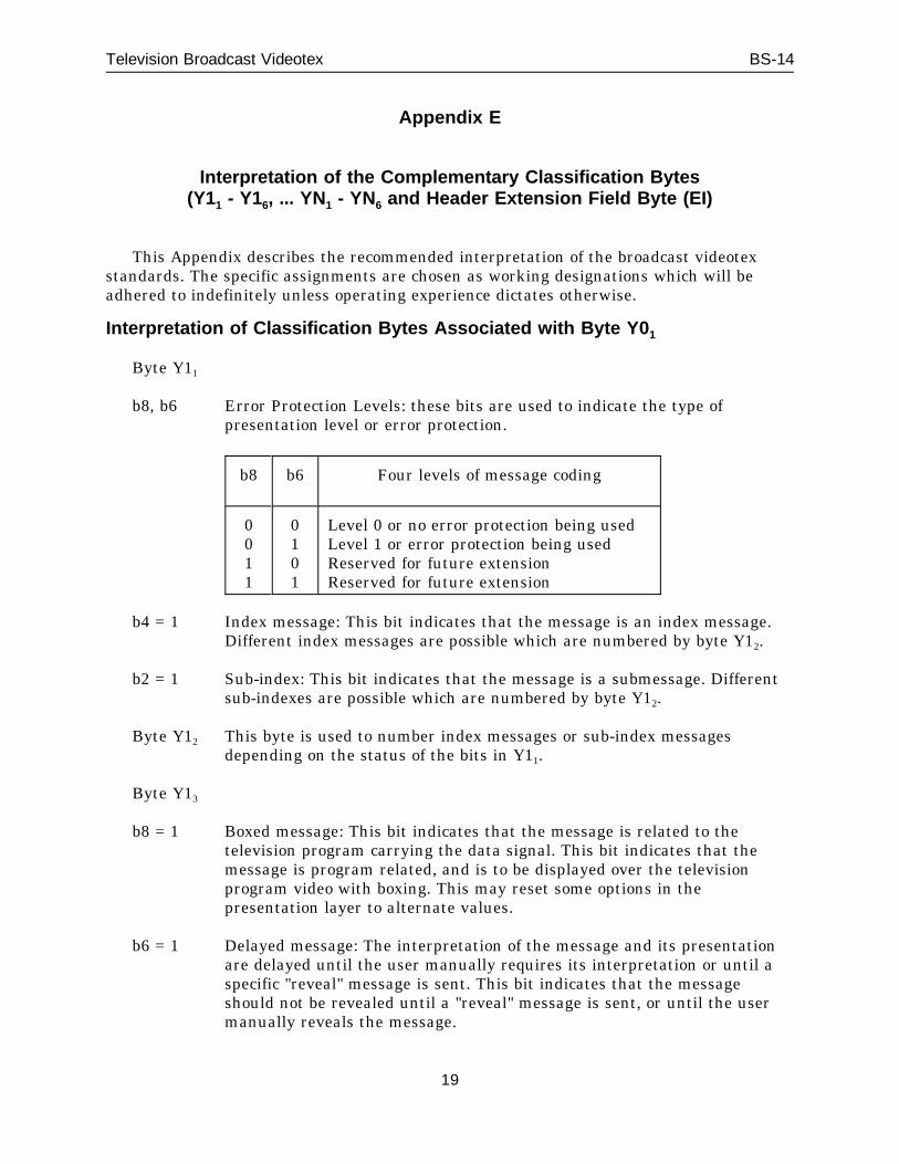
Interpretation of the Complementary Classification Bytes(Y11 - Y16, ... YN1 - YN6 and Header Extension Field Byte (EI)
This Appendix describes the recommended interpretation of the broadcast videotexstandards. The specific assignments are chosen as working designations which will beadhered to indefinitely unless operating experience dictates otherwise.
Interpretation of Classification Bytes Associated with Byte Y0 1
Byte Y11
b8, b6 Error Protection Levels: these bits are used to indicate the type ofpresentation level or error protection.
b8 b6 Four levels of message coding
0011
0101
Level 0 or no error protection being usedLevel 1 or error protection being usedReserved for future extensionReserved for future extension
b4 = 1 Index message: This bit indicates that the message is an index message.Different index messages are possible which are numbered by byte Y12.
b2 = 1 Sub-index: This bit indicates that the message is a submessage. Differentsub-indexes are possible which are numbered by byte Y12.
Byte Y12 This byte is used to number index messages or sub-index messagesdepending on the status of the bits in Y11.
Byte Y13
b8 = 1 Boxed message: This bit indicates that the message is related to thetelevision program carrying the data signal. This bit indicates that themessage is program related, and is to be displayed over the televisionprogram video with boxing. This may reset some options in thepresentation layer to alternate values.
b6 = 1 Delayed message: The interpretation of the message and its presentationare delayed until the user manually requires its interpretation or until aspecific "reveal" message is sent. This bit indicates that the messageshould not be revealed until a "reveal" message is sent, or until the usermanually reveals the message.
19
Television Broadcast Videotex BS-14
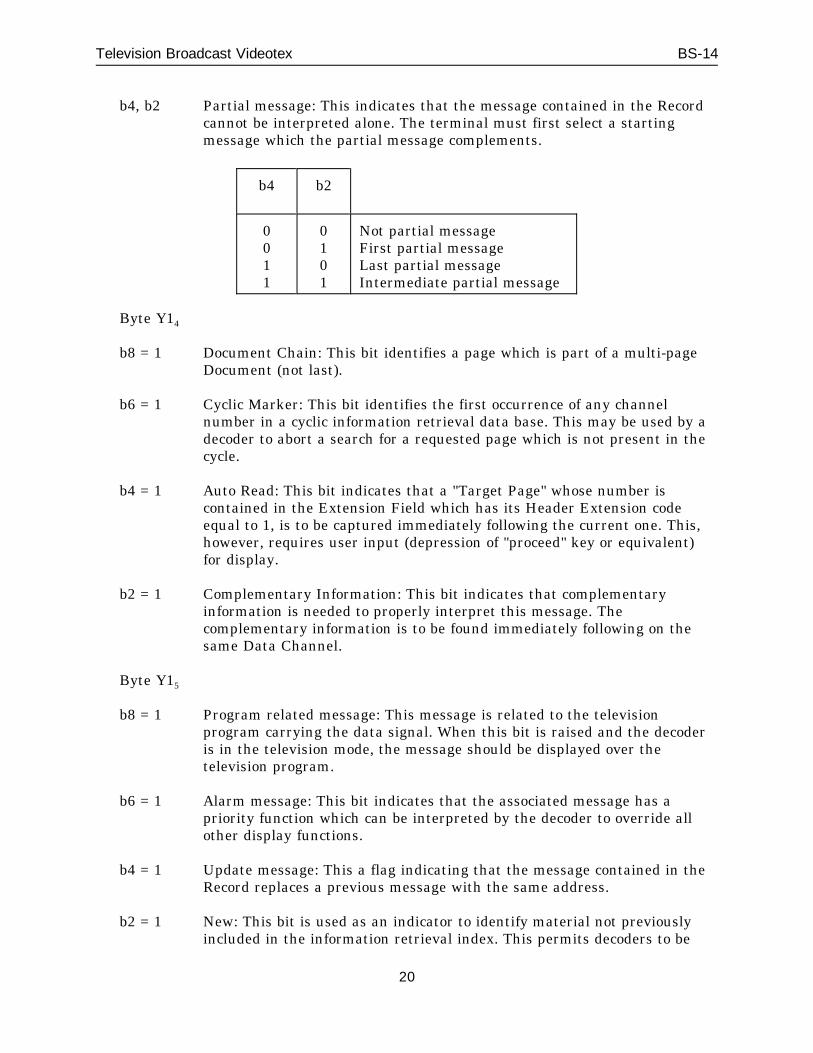
b4, b2 Partial message: This indicates that the message contained in the Recordcannot be interpreted alone. The terminal must first select a startingmessage which the partial message complements.
b4 b2
0011
0101
Not partial messageFirst partial messageLast partial messageIntermediate partial message
Byte Y14
b8 = 1 Document Chain: This bit identifies a page which is part of a multi-pageDocument (not last).
b6 = 1 Cyclic Marker: This bit identifies the first occurrence of any channelnumber in a cyclic information retrieval data base. This may be used by adecoder to abort a search for a requested page which is not present in thecycle.
b4 = 1 Auto Read: This bit indicates that a "Target Page" whose number iscontained in the Extension Field which has its Header Extension codeequal to 1, is to be captured immediately following the current one. This,however, requires user input (depression of "proceed" key or equivalent)for display.
b2 = 1 Complementary Information: This bit indicates that complementaryinformation is needed to properly interpret this message. Thecomplementary information is to be found immediately following on thesame Data Channel.
Byte Y15
b8 = 1 Program related message: This message is related to the televisionprogram carrying the data signal. When this bit is raised and the decoderis in the television mode, the message should be displayed over thetelevision program.
b6 = 1 Alarm message: This bit indicates that the associated message has apriority function which can be interpreted by the decoder to override allother display functions.
b4 = 1 Update message: This a flag indicating that the message contained in theRecord replaces a previous message with the same address.
b2 = 1 New: This bit is used as an indicator to identify material not previouslyincluded in the information retrieval index. This permits decoders to be
20
Television Broadcast Videotex BS-14
programmed to capture all new pages, or alternatively only those within aspecific channel.
Byte Y16
Version: This byte, with four usage bits, is used to specify a versionnumber of an information retrieval page.
Interpretation of Classification Bytes Associated with Byte Y0 2
Bytes Y21
Terminal: This byte, with four usage bits, is used to specify terminalfunctions.
Bytes Y22 - Y26 ... YN1 - YN6
These bytes are not defined in this specification and are reserved forfuture extension.
Interpretation of Header Extension Field Byte (EI)
The first byte of the Header Extension Field is an extension field introducer byte(EI), with bit designations as follows:
b8 = 0 indicates last Extension Field
= 1 indicates further Header Extension Field(s) to follow (E1 ... EN)
b6, b4, b2 indicate Header Extension Code assignments as follows:
= 0 reserved
= 1 cross reference;identifies a Record to be captured immediately following the currentone.
= 2-7 reserved for future extension.
The second byte (ES) of the Header Extension Field indicates the number ofbytes of Extension Field information in the current Extension Field.
21