assembly preparations for the international erl cryomodule ... · the second cavity is in the fi...
TRANSCRIPT

ASSEMBLY PREPARATIONS FOR THE INTERNATIONAL ERL CRYOMODULE AT DARESBURY LABORATORY
P. A. McIntosh, R. Bate, C. D. Beard, M. A. Cordwell, D. M. Dykes, S. M. Pattalwar and J. Strachan, STFC Daresbury Laboratory, Warrington, UK
S. Belomestnykh, E. Chojnacki, Z. Conway, G. Hoffstaetter, M. Liepe, H. Padamsee, P. Quigley, Cornell University, Ithaca, NY, U.S.A..
D. Proch and J. Sekutowicz, DESY, Hamburg, Germany. A. Büchner, F. Gabriel and P. Michel, FZR Rossendorf, Strahlungsquelle ELBE, Dresden, Germany
J. N. Corlett, D. Li and S. Lidia, LBNL, Berkeley, CA, U.S.A. T. Kimura and T. I. Smith, HEPL Stanford University, Stanford, CA, U.S.A.
S. Koscielniak and R. Laxdal, TRIUMF, Vancouver, Canada.
Abstract The collaborative development of an optimised
cavity/cryomodule solution for application on ERL facilities has now progressed to final assembly and testing of the cavity string components and their subsequent cryomodule integration. This paper outlines the testing and verification processes for the various cryomodule sub-components and details the methodology utilised for final cavity string integration. The paper also highlights the modifications required to integrate this new cryomodule into the existing ALICE cryo-plant facility at Daresbury Laboratory.
INTRODUCTION Preparations for the assembly of a new
Superconducting RF (SRF) cryomodule, which has been developed for long-term high Qext and CW operation for application on Energy Recovery Linac (ERL) accelerators, is well underway at Daresbury Laboratory [1].
Table 1: Cryomodule Design Parameters
Parameter Value Frequency (GHz) 1.3 Number of Cavities 2 Number of Cells per Cavity 7 Cryomodule Length (m) 3.6 R/Q (Ω) 762 Eacc (MV/m) > 20 Epk/Eacc 2.23 Hpk/Eacc (Oe/MV/m) 46.9 Cryomodule Energy Gain (MeV) > 32 Qo >1 x 10¹⁰ Qext 4 x 10⁶ - 108 Maximum Beam Current 100 mA Max. Cavity Forward Power (kW) 25 SW
To date, the international partners who have
participated in this collaborative development (Cornell and Stanford Universities, Daresbury Laboratory, DESY, FZD-Rossendorf, Lawrence Berkeley Laboratory, and
more latterly TRIUMF) have identified appropriate sub-system solutions to achieve the fundamental requirements for this new cryomodule, which have been reported previously elsewhere [2]. Table 1 highlights the primary cryomodule design parameters, which will be installed on the ALICE ERL accelerator at Daresbury Laboratory and validated with beam in 2010.
CAVITY DESIGN AND FABRICATION
Figure 1: 7-cell cavity after final electron-beam welding.
Two seven-cell niobium cavities have been fabricated (Figure 1). The section from the first to the last equator was cut from two seven-cell superstructure cavities provided by DESY [3]. The outer half-cells and associated beam pipes (end groups) are of a new design developed by LBNL, Daresbury and Cornell. Their geometries were optimized to facilitate the propagation of higher order mode power to ferrite-lined beam-pipe loads. Figure 2 shows a schematic of the end cell geometries and integrated cavity string assembly.
Figure 2: ERL Cavity String Assembly
After fabrication, the cavities have been tuned for field flatness of the π-mode. As the gradient will be 20 MV/m or less in operation, only BCP treatment is used for the final stage of cavity preparation. So far, one of the two
J. Sears, V. Shemelin and V. Veshcherevich,
THPPO098 Proceedings of SRF2009, Berlin, Germany
09 Cavity preparation and production
864
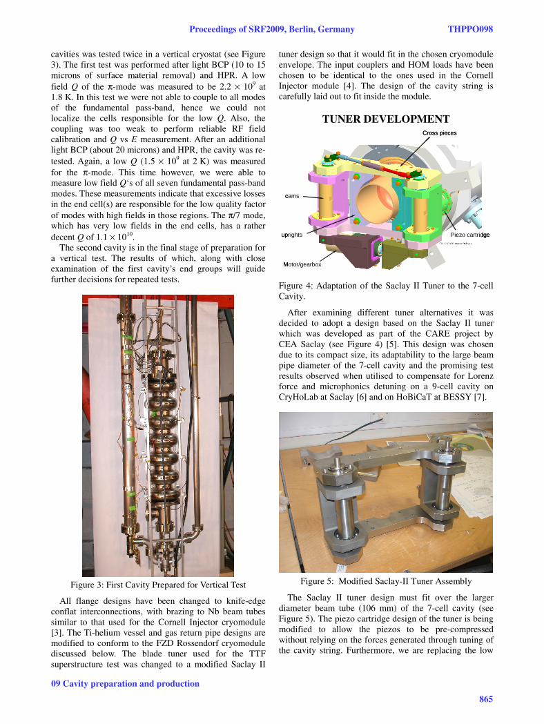
cavities was tested twice in a vertical cryostat (see Figure 3). The first test was performed after light BCP (10 to 15 microns of surface material removal) and HPR. A low field Q of the π-mode was measured to be 2.2 × 10⁹ at 1.8 K. In this test we were not able to couple to all modes of the fundamental pass-band, hence we could not localize the cells responsible for the low Q. Also, the coupling was too weak to perform reliable RF field calibration and Q vs E measurement. After an additional light BCP (about 20 microns) and HPR, the cavity was re-tested. Again, a low Q (1.5 × 10⁹ at 2 K) was measured for the π-mode. This time however, we were able to measure low field Q‘s of all seven fundamental pass-band modes. These measurements indicate that excessive losses in the end cell(s) are responsible for the low quality factor of modes with high fields in those regions. The π/7 mode, which has very low fields in the end cells, has a rather decent Q of 1.1 × 10¹⁰.
The second cavity is in the final stage of preparation for a vertical test. The results of which, along with close examination of the first cavity’s end groups will guide further decisions for repeated tests.
Figure 3: First Cavity Prepared for Vertical Test
All flange designs have been changed to knife-edge conflat interconnections, with brazing to Nb beam tubes similar to that used for the Cornell Injector cryomodule [3]. The Ti-helium vessel and gas return pipe designs are modified to conform to the FZD Rossendorf cryomodule discussed below. The blade tuner used for the TTF superstructure test was changed to a modified Saclay II
tuner design so that it would fit in the chosen cryomodule envelope. The input couplers and HOM loads have been chosen to be identical to the ones used in the Cornell Injector module [4]. The design of the cavity string is carefully laid out to fit inside the module.
TUNER DEVELOPMENT
uprights
Cross pieces
cams
Motor/gearbox
Piezo cartridgeuprights
Cross pieces
cams
Motor/gearbox
Piezo cartridge
Figure 4: Adaptation of the Saclay II Tuner to the 7-cell Cavity.
After examining different tuner alternatives it was decided to adopt a design based on the Saclay II tuner which was developed as part of the CARE project by CEA Saclay (see Figure 4) [5]. This design was chosen due to its compact size, its adaptability to the large beam pipe diameter of the 7-cell cavity and the promising test results observed when utilised to compensate for Lorenz force and microphonics detuning on a 9-cell cavity on CryHoLab at Saclay [6] and on HoBiCaT at BESSY [7].
Figure 5: Modified Saclay-II Tuner Assembly
The Saclay II tuner design must fit over the larger diameter beam tube (106 mm) of the 7-cell cavity (see Figure 5). The piezo cartridge design of the tuner is being modified to allow the piezos to be pre-compressed without relying on the forces generated through tuning of the cavity string. Furthermore, we are replacing the low
Proceedings of SRF2009, Berlin, Germany THPPO098
09 Cavity preparation and production
865

voltage piezo stack with a high voltage stack to achieve a higher degree of stiffness.
INPUT COUPLER PREPARATIONS The chosen solution for a suitable input coupler,
capable of delivering 20 kW CW in standing wave, whilst also providing adjustability in terms of its Qext setting, is the Cornell ERL injector coupler (see Figure 6) [8]. CPI have successfully fabricated a number of these couplers and the power handling capability has been proven up to 50 kW CW in travelling wave.
Original
Modified80K Intercept
removed
2K5K
80K 300K
Cold section shortened by
15mm
Original
Modified80K Intercept
removed
2K5K
80K 300K
Cold section shortened by
15mm Figure 6: Original and Modified Cornell ERL Injector Coupler
To allow for the insertion of the cold part of the coupler and the modified cavity string into the cryomodule, its total length has been shortened by removal of the secondary 80 K thermal intercept which was fundamentally required for 50 kW operation. This enables the cavity string to be inserted into the cryomodule without interfering with the cryomodule vessel. The modified coupler heat loads due to these modifications are shown in Table 2.
Table 2: Modified Cornell Coupler Heat Loads
Parameter Original Modified Max Power (kW) 50 TW 20 SW Antenna Stroke (mm) >15 <15 Heat Leak to 2K (W) 0.23 0.13 Heat Leak to 5K (W) 1.7 2.5 Heat Leak to 80K (W) 43 34
Prior to assembly of the couplers into the cavity string,
they must be rigorously cleaned and inspected, before being baked and high power RF processed. Both couplers have been assembled onto their respective cold and warm baking stations (see Figure 7 a) and b)) and baked at 150 C for 24 hours.
Figure 7: a) Cold and b) Warm Coupler Bake Assemblies at Daresbury
The couplers have now been assembled in a back-to-back configuration, onto a high power coupling box to allow for high power conditioning (see Figure 8).
Figure 8: Input Coupler RF Conditioning Assembly
RF power will be limited to ~10 kW CW during conditioning, as gaseous helium (GHe) cooling will not be available. Pulsed conditioning will then be performed up to the 30 kW limit of the IOT test stand at Daresbury (see Figure 9).
THPPO098 Proceedings of SRF2009, Berlin, Germany
09 Cavity preparation and production
866
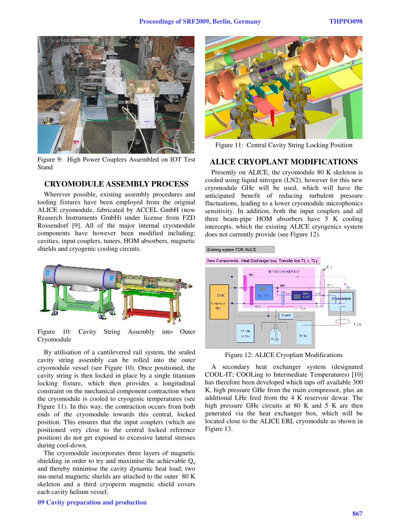
Figure 9: High Power Couplers Assembled on IOT Test Stand
CRYOMODULE ASSEMBLY PROCESS Wherever possible, existing assembly procedures and
tooling fixtures have been employed from the original ALICE cryomodule, fabricated by ACCEL GmbH (now Reaserch Instruments GmbH) under license from FZD Rossendorf [9]. All of the major internal cryomodule components have however been modified including; cavities, input couplers, tuners, HOM absorbers, magnetic shields and cryogenic cooling circuits.
Figure 10: Cavity String Assembly into Outer Cryomodule
By utilisation of a cantilevered rail system, the sealed cavity string assembly can be rolled into the outer cryomodule vessel (see Figure 10). Once positioned, the cavity string is then locked in place by a single titanium locking fixture, which then provides a longitudinal constraint on the mechanical component contraction when the cryomodule is cooled to cryogenic temperatures (see Figure 11). In this way, the contraction occurs from both ends of the cryomodule towards this central, locked position. This ensures that the input couplers (which are positioned very close to the central locked reference position) do not get exposed to excessive lateral stresses during cool-down.
The cryomodule incorporates three layers of magnetic shielding in order to try and maximise the achievable Qo and thereby minimise the cavity dynamic heat load; two mu-metal magnetic shields are attached to the outer 80 K skeleton and a third cryoperm magnetic shield covers each cavity helium vessel.
Figure 11: Central Cavity String Locking Position
ALICE CRYOPLANT MODIFICATIONS Presently on ALICE, the cryomodule 80 K skeleton is
cooled using liquid nitrogen (LN2), however for this new cryomodule GHe will be used, which will have the anticipated benefit of reducing turbulent pressure fluctuations, leading to a lower cryomodule microphonics sensitivity. In addition, both the input couplers and all three beam-pipe HOM absorbers have 5 K cooling intercepts, which the existing ALICE cryogenics system does not currently provide (see Figure 12).
Figure 12: ALICE Cryoplant Modifications
A secondary heat exchanger system (designated COOL-IT; COOLing to Intermediate Temperatures) [10] has therefore been developed which taps off available 300 K, high pressure GHe from the main compressor, plus an additional LHe feed from the 4 K reservoir dewar. The high pressure GHe circuits at 80 K and 5 K are then generated via the heat exchanger box, which will be located close to the ALICE ERL cryomodule as shown in Figure 13.
Proceedings of SRF2009, Berlin, Germany THPPO098
09 Cavity preparation and production
867
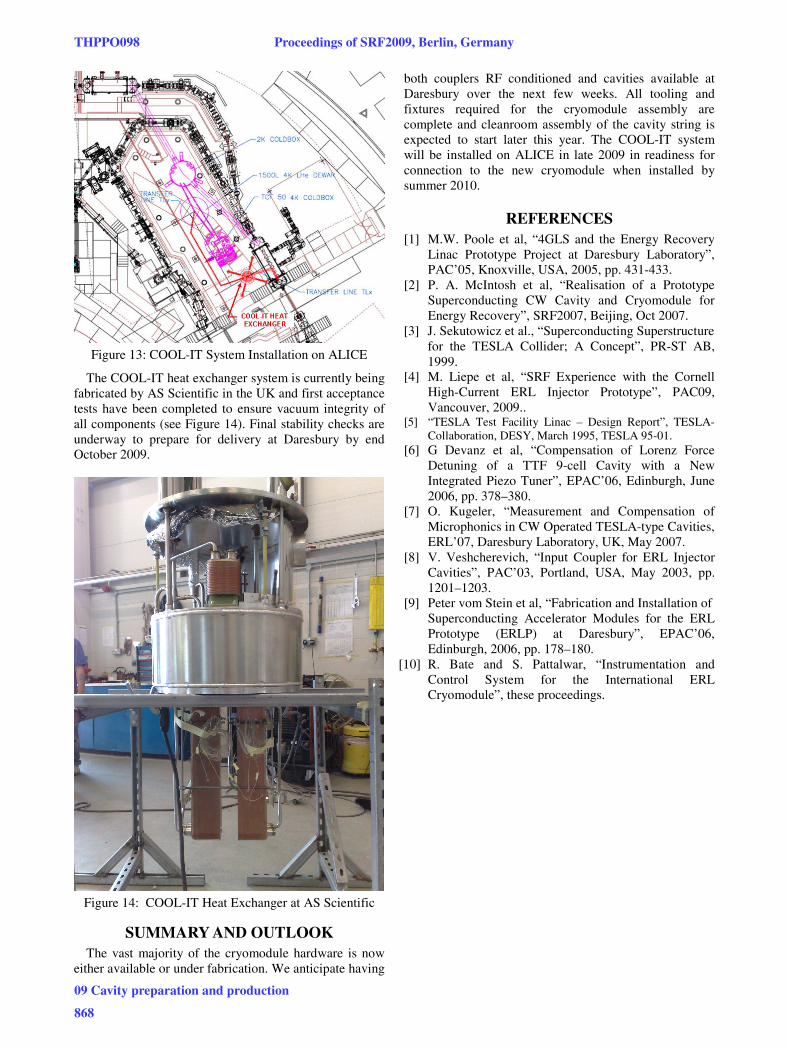
Figure 13: COOL-IT System Installation on ALICE
The COOL-IT heat exchanger system is currently being fabricated by AS Scientific in the UK and first acceptance tests have been completed to ensure vacuum integrity of all components (see Figure 14). Final stability checks are underway to prepare for delivery at Daresbury by end October 2009.
Figure 14: COOL-IT Heat Exchanger at AS Scientific
SUMMARY AND OUTLOOK The vast majority of the cryomodule hardware is now
either available or under fabrication. We anticipate having
both couplers RF conditioned and cavities available at Daresbury over the next few weeks. All tooling and fixtures required for the cryomodule assembly are complete and cleanroom assembly of the cavity string is expected to start later this year. The COOL-IT system will be installed on ALICE in late 2009 in readiness for connection to the new cryomodule when installed by summer 2010.
REFERENCES [1] M.W. Poole et al, “4GLS and the Energy Recovery
Linac Prototype Project at Daresbury Laboratory”, PAC’05, Knoxville, USA, 2005, pp. 431-433.
[2] P. A. McIntosh et al, “Realisation of a Prototype Superconducting CW Cavity and Cryomodule for Energy Recovery”, SRF2007, Beijing, Oct 2007.
[3] J. Sekutowicz et al., “Superconducting Superstructure for the TESLA Collider; A Concept”, PR-ST AB, 1999.
[4] M. Liepe et al, “SRF Experience with the Cornell High-Current ERL Injector Prototype”, PAC09, Vancouver, 2009..
[5] “TESLA Test Facility Linac – Design Report”, TESLA-Collaboration, DESY, March 1995, TESLA 95-01.
[6] G Devanz et al, “Compensation of Lorenz Force Detuning of a TTF 9-cell Cavity with a New Integrated Piezo Tuner”, EPAC’06, Edinburgh, June 2006, pp. 378–380.
[7] O. Kugeler, “Measurement and Compensation of Microphonics in CW Operated TESLA-type Cavities, ERL’07, Daresbury Laboratory, UK, May 2007.
[8] V. Veshcherevich, “Input Coupler for ERL Injector Cavities”, PAC’03, Portland, USA, May 2003, pp. 1201–1203.
[9] Peter vom Stein et al, “Fabrication and Installation of Superconducting Accelerator Modules for the ERL
Prototype (ERLP) at Daresbury”, EPAC’06, Edinburgh, 2006, pp. 178–180.
[10] R. Bate and S. Pattalwar, “Instrumentation and Control System for the International ERL Cryomodule”, these proceedings.
THPPO098 Proceedings of SRF2009, Berlin, Germany
09 Cavity preparation and production
868