lecture 8 cryomodule design
TRANSCRIPT
Lecture 8Cryomodule Design
J. G. Weisend II
Summer 2021
Lecture 8| Cryomodule Design
1

Goals
▪Define cryomodule
▪Describe the two principal types of cryomodules and their relative advantages
▪Discuss cryomodule requirements
▪Design considerations
▪Present examples of cryomodules• TESLA
• LCLS II• ESS
Note: some of this talk is taken from Tom Peterson’s 2019 USPAS lecture
Summer 2021
Lecture 8| Cryomodule Design
Slide 2

Cryomodules
▪ Cryomodules are cryostats designed to contain Superconducting Radio Frequency (SRF) cavities• The term cryomodule was originally coined at Jlab.
▪ SRF cavities are a very popular application of superconductivity in accelerators. There are easily more than a dozen SRF based accelerators in operation, under construction or under design worldwide. Some of these applications are very large scale.
▪ The principles of cryomodule design are generally applicable to all cryostats.
▪ One feature of cryomodules is that due to losses in RF superconductivity, cryomodules may have large dynamic heat loads. This feature can drive design choices.
▪ He II (lecture 13) at ~ 2 K is the most common coolant
▪ The design and prototyping of a new cryomodule can take a number of years.
Summer 2021
Lecture 8| Cryomodule Design
Slide 3

Cryomodule Types
Cryomodules can be divided into two principal types:
1. Separated Cryomodules
The cryomodules in the beam line are separated from each other by room temperature sections that contain other beam line components such as magnets and beam diagnostics. The cryomodules typically have their own vacuum space and are cooled via a cryogenic distribution line that runs parallel to the beam line. In 2 K systems, the He II is created at each cryomodule. Examples include ESS, SNS, JLAB, Sprial 2, FRIB
2. String Cryomodules
The cryomodules are connected together in a long string of common vacuum and cryogenic space. There are no room temperature sections and no parallel cryogenic distribution line. The cryomodules are cooled in series and in the case of 2 K systems the He II is created at one end of the string.Examples include: XFEL, LCLS II, SHINE, ILC
Summer 2021
Lecture 8| Cryomodule Design
Slide 4

Example of a Separated Cryomodule: ESS
Summer 2021
Lecture 8| Cryomodule Design

Example of a String Cryomodule: XFEL
Summer 2021
Lecture 8| Cryomodule Design
Slide 6
Separated Cryomodules
Advantages:
• Flexibility and maintainability. Depending on design details, cryomodules may be repaired or replaced without warming up large sections of the accelerator.
• Separate vacuum spaces can reduce accident consequences
• Components not requiring cryogenic temperatures such as beam diagnostics can remain warm
• May be able to handle higher total heat loads
Disadvantages:
• Higher cost
• Higher static heat loadsSummer 2021
Lecture 8| Cryomodule Design
Slide 7
String Cryomodules
Advantages:
• Lower cost: no need for parallel transfer line and fewer valves required
• Fewer warm/cold transitions result in lower static heat loads
Disadvantages:
• Less flexibility. Entire string may have to be warmed up to replace or repair one cryomodule
• Common vacuum space can increase consequences of accidents
• May not be able to handle high dynamic loads
• All components have to function at cryogenic temperaturesSummer 2021
Lecture 8| Cryomodule Design
Slide 8

Cryomodule requirements Major components
▪Dressed RF cavities
▪RF power input couplers
▪ Intermediate temperature thermal shield or shields
▪Heat exchanger for 4.5 K to 2.2 K precooling of the liquid supply flow if stand-alone style
▪Cryogenic valves if stand-alone style
▪Pipe and cavity support structure
▪ Instrumentation -- RF, pressure, temperature, etc.
▪Connections for helium supply and return
Summer 2021
Lecture 8| Cryomodule Design
9

Cryomodule requirements Major interfaces
▪Connections for helium supply and return
▪Vacuum vessel support structure
▪Beam tube connections at the cryomodule ends
▪RF waveguide to input couplers
▪ Instrumentation connectors on the vacuum shell
▪Alignment fiducials on the vacuum shell with reference to cavity positions.
Summer 2021
Lecture 8| Cryomodule Design
10
Design Considerations
▪Cooling arrangement for integration into cryo system
▪Pipe sizes for steady-state and emergency venting
▪Pressure stability factors
▪Heat load estimates and uncertainty
▪Options for handling 4.5 K (or perhaps 5 K - 8 K) thermal intercept flow
▪Alignment and support stability
▪Thermal contraction and fixed points with closed ends
Summer 2021
Lecture 8| Cryomodule Design
11
Design Considerations
▪Support structure • Stiffness of pipe if used as support backbone • Or other support structure options
▪Emergency venting scenarios drive pipe sizes and influence segmentation • Cold MAWP may be low, driving up pipe sizes and/or reducing spacing
between relief vent ports • Trade-off of pipe size with vent spacing
• Thermal shield pipe may also require frequent venting » 5 K may have large surface area for large heat flux
» 70 K helium typically starts at a high pressure
▪Liquid management length • May want to subdivide strings for liquid management due to large specific
liquid flow rate per cavity
Summer 2021
Lecture 8| Cryomodule Design
12
Summer 2021
Lecture 8| Cryomodule Design
13

Example #1TESLA Cryomodule
▪Developed during the 1990’s at DESY Lab (Hamburg, Germany) as the SRF solution for the proposed International Linear Collider (ILC)• 4 generations of TESLA cryomodule have been designed based on
optimization and prototype results.
▪ ILC Design Drivers• Cost – MultiBillion $ project. Anything that can be done to reduce cost will
make the project more likely• Heat Leak - SRF cavities have dynamic heat loads but large number of
cryomodules also drives the design to reduce static heat leak• Reliability & availability – frequent repairs just aren’t an option – drives
accessibility decisions plus extensive QA/QC program
• Presence of superconducting magnets (4.5 K now 2 K)• Low pressure return line must be sized large enough so that pressure drop
in vapor is small enough that the bath temperature is 2 K at the cavities furthest from the refrigerator
• Tight alignment requirements for both magnets and cavities
▪ These requirements led to the choice of string style cryomodules.Summer 2021
Lecture 8| Cryomodule Design
14

Early Design Choices
▪Long cryogenic stretches with a minimum number of warm / cold transitions• Reduces heat leak• Reduces cost
▪No parallel transfer line to move fluids• Cryomodules themselves are the transfer line• Reduces heat leak and cost
▪Multiple thermal shields and MLI blankets• Adds costs but reduces heat leak at low temperatures
▪Use He vapor line as structural backbone
Summer 2021
Lecture 8| Cryomodule Design
15
Early Design Choices
◼Use welded connections whenever possible – minimize cold flange connections◼Reduces cost◼Improves reliability
◼Design system so that cavities & magnets can be aligned during warm assembly & maintain their alignment during cool down
Summer 2021
Lecture 8| Cryomodule Design
16
TESLA 1st Generation Cryomodule Design
Summer 2021
Lecture 8| Cryomodule Design
17
▪Eight 9 cell SRF cavities + 1 s/c magnet package
▪Components are tied to 300 mm pipe strongback
▪2 thermal shields (40/80 K and 5 K)
▪Cold mass hangs from 3 support posts• Cold Mass along with 2 outer posts move towards fixed center post during cool down (ends move 15 mm)
▪Thermal shields are made many Al pieces connected via threaded fasteners
▪Thermal shield pipes are SS, connected to shields via copper straps

1st Generation TESLA CMNote position of 2 phase pipe
& use of copper straps
Summer 2021
Lecture 8| Cryomodule Design
18

Side View of 1st Generation TESLA Cryomodule(each end of 300 mm tube shrinks
15 mm upon cooldown)
Summer 2021
Lecture 8| Cryomodule Design
19

TESLA Cryomodule
Summer 2021
Lecture 8| Cryomodule Design
20

Coupler Movement
▪Power couplers have a fixed position to the outside world
▪Movement of 300 mm pipe upon cool down means you can:• Rigidly fix cavities to 300 mm pipe and have flexible couplers OR
• Fix cavities in position with couplers and let 300 mm pipe move wrt the cavities
▪1st generation design used flexible coupler option
Summer 2021
Lecture 8| Cryomodule Design
21
Changes to 2nd Generation Design
▪Redesign of Aluminum shields
• Larger sections welded rather than connected by fasteners –significant savings in cost & ease of assembly
• “Finger joints” for weld relief
▪Use Al shield cooling pipes extruded with shields and Al/SS transition joints at interconnects
• Eliminates copper straps – significant cost savings & reliability improvement
• CERN LHC approach
▪Rationalize tolerances for vacuum vessel• Cost savings• More realistic results for coupler interfaces
Summer 2021
Lecture 8| Cryomodule Design
22
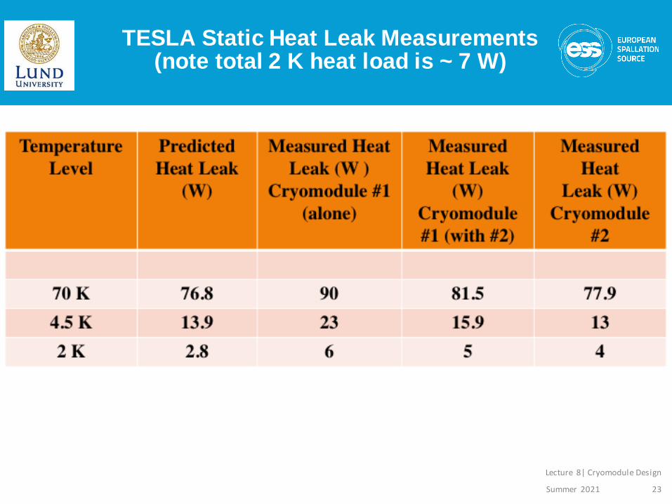
TESLA Static Heat Leak Measurements(note total 2 K heat load is ~ 7 W)
Summer 2021
Lecture 8| Cryomodule Design
23
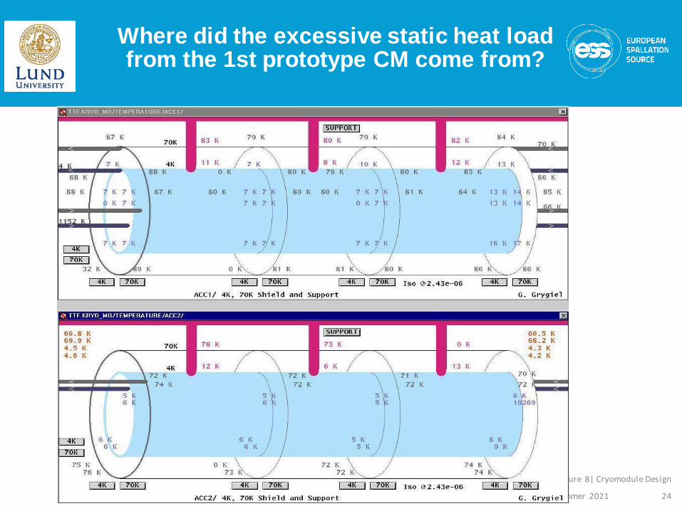
Where did the excessive static heat load from the 1st prototype CM come from?
Summer 2021
Lecture 8| Cryomodule Design
24

Alignment ResultsCryomodule 2
Summer 2021
Lecture 8| Cryomodule Design
25
-0.6
-0.5
-0.4
-0.3
-0.2
-0.1
0
0.1
0.2
0.3
0.4
0 1 2 3 4 5 6 7 8 9 10 11 12
WPM position [m]
1/11/98 11.44
1/2/99 11.42
22/3/99 10.40
Ho
rizo
nta
l d
isp
lacem
en
t [m
m]
• Measured in Real time via Wire Position Measuring System
• ILC requirements +/- 0.5 mm for cavities and +/-0.25 mm
for magnet

Changes to 3rd Generation Design
▪Moved 2 Phase line & reduced vacuum vessel to a smaller standard size pipe
▪Relocated 3rd support post closer to s/c magnet assembly to improve stiffness
▪Combination of linear bearings & Invar rod decouples cavities from 300 mm tube and allows use of semi-rigid couplers
▪This design is the basis of the 100 Cryomodules used in the European XFEL at DESY.
Summer 2021
Lecture 8| Cryomodule Design
26

3rd Generation TESLA CryomoduleILC Prototype
Summer 2021
Lecture 8| Cryomodule Design
27
2.2 K forward
4.5 K forward
40 K forward
2 K 2-phase
cavity
2 K return
80 K return
4.5 K return
cool down/
warmup
support
coupler
300 mm

Linear Bearing Concept for Cavity Connection
Summer 2021
Lecture 8| Cryomodule Design
28

Current ILC Design(4th Generation)
▪Move magnet package to center of cryomodule• Optimal position for maintaining magnet alignment
▪Operate magnet at 2 K rather than 4.5 K• Decouples thermal shield circuit from magnet allowing shield to be optimized at 5 – 8 K.
• Reduced temperature can yield higher magnet performance & eliminates any impact due to shield circuit issues
• Requires conduction cooled HTS lead – issues with heat sinking
▪Will likely eliminate the 5 K shield but keep 5 K heat sink.
Summer 2021
Lecture 8| Cryomodule Design
29
The TESLA cryomodule designis very popular
In addition to being used at the European XFEL (DESY) it is also used with some variations at other large FEL projects
SHINE (Shanghai) – Under construction
LCLS II (SLAC, USA) – Under construction
NLS UK - Proposed
It is also of course the cryomodule for ILC (if built)
Summer 2021
Lecture 8| Cryomodule Design
30

Example 2 : LCLS II
▪Like XFEL, a Free Electron LASER driven by an electron llinac.
▪But LCLS II is a continuous wave rather than pulse RF system so there is much more dynamic heat load to the 2 K space
▪ In addition, the SLAC tunnel has a significant slope to it
▪These factors required changes:
• Series Parallel mode with separate He II spaces in eachcryomodule
• Larger connection between Cavities and He II to stay within 1 W/m2 heat transfer limit
• Removal of 5 K thermal shield
Summer 2021
Lecture 8| Cryomodule Design
31

Cryomodules Cooled in”Series Parallel ” mode
Summer 2021
Lecture 8| Cryomodule Design
32

LCLS II Cryomodule: an adaptation of the XFEL design
Summer 2021
Lecture 8| Cryomodule Design
33

Example 3 ESS Elliptical Cavity
Cryomodule
▪The European Spallation Source (ESS) is a neutron source that use a high energy Proton linac to produce neutrons via spallation
▪Similar though much brighter than the SNS (USA) with a much higher energy linac (2 GeV and 5 MW)
▪Only 43 cryomodules required so cost and heat leak per cryomodule less of an issue than ILC or even XFEL
▪However the goal for availability of ESS is 95% thus reliability and maintainability are very important. This leads to:• Having as many systems at room temperature as possible
• Having the ability to repair or replace cryomodules without warming up the entire linac
▪This leads us to separated cryomodules with a parallel transfer line
Summer 2021
Lecture 8| Cryomodule Design
34
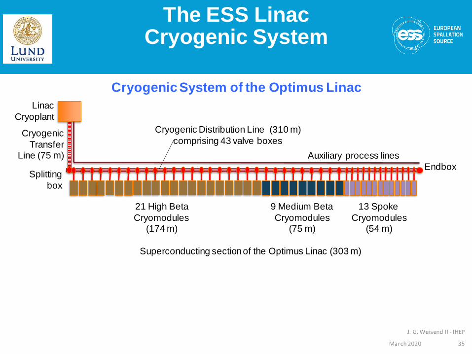
Cryogenic Distribution Line (310 m)
comprising 43 valve boxes
Endbox
Cryogenic
Transfer Line (75 m)
Splitting
box
The ESS Linac Cryogenic System
21 High Beta
Cryomodules (174 m)
9 Medium Beta
Cryomodules(75 m)
13 Spoke
Cryomodules(54 m)
Linac
Cryoplant
Superconducting section of the Optimus Linac (303 m)
Auxiliary process lines
Cryogenic System of the Optimus Linac
35March 2020
J. G. Weisend II - IHEP
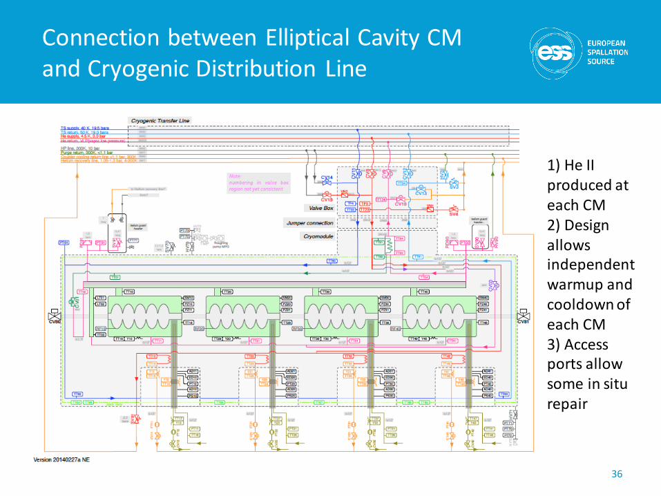
Connection between Elliptical Cavity CM and Cryogenic Distribution Line
36
1) He II produced at each CM2) Design allows independent warmup and cooldown of each CM3) Access ports allow some in situ repair

▪ Similar to CEBAF/SNS cryomodule concept with 4 cavities per cryomodule
▪ Common design for medium (6 cells) and high beta (5 cells) cavities
Proton Beam
Jumper connection
Cold to warm transition
Magneticshielding
Power coupler
Cavity withHelium tank
Diphasic He pipe
Thermal shielding
Regulation He valve
Intercavitiesbelows
Vacuum valve
Spaceframesupport Heat exchanger
Alignement fiducial
37
Elliptical Cavity Cryomodules

Prototype Cryomodule at ESS
38

CDS-EL Components installation in Tunnel
39