appendix f - california
TRANSCRIPT
Appendix F
Geotechnical Evaluation
Geotechnical Engineering Report
Athos Solar Facility
Desert Center, California
June 29, 2018
Terracon Project No. 60185052
Prepared for:
Intersect Power
San Francisco, California
Prepared by:
Terracon Consultants, Inc.
Tustin, California
Draft
Terracon Consultants, Inc. 1421 Edinger Avenue, Suite C Tustin, California 92780
P [949] 261.0051 F [949] 261.6110 terracon.com
June 29, 2018
Intersect Power
2 Embarcadero Center, 7th Floor
San Francisco, CA 94118
Attn: Mr. Seth Israel, Partner
M: 415-312-9911
RE: Geotechnical Engineering Report
Athos Solar Facility
Desert Center, Riverside County, California
Terracon Project No. 60185052
Dear Mr. Israel,
Terracon Consultants, Inc. (Terracon) has completed the geotechnical engineering services for
the above referenced project. These services were performed in general accordance with our
proposal, and discussions with the client. This report provides a description of subsurface
exploration, in-situ soil resistivity testing, and laboratory testing. Based on field and laboratory
test results, this report provides geotechnical engineering recommendations concerning
earthwork and the design and construction of the proposed structures and site development
elements for this project.
We appreciate the opportunity to be of service to you on this project. If you have any questions
concerning this report, or if we may be of further service, please contact us.
Sincerely,
Terracon Consultants, Inc.
Joshua R. Morgan P.E. F. Fred Buhamdan, P.E.
Project Engineer Principal
Draft
Geotechnical Engineering Report Athos Solar Facility ■ Desert Center, California June 29, 2018 ■ Terracon Project No. 60185052
Responsive ■ Resourceful ■ Reliable i
TABLE OF CONTENTS
1.0 INTRODUCTION ............................................................................................................. 1
2.0 PROJECT INFORMATION .............................................................................................. 1
2.1 Project Description .............................................................................................. 1
2.2 Site Location and Description ............................................................................. 2
3.0 SUBSURFACE CONDITIONS ......................................................................................... 3
3.1 Site Geology ....................................................................................................... 3
3.2 Typical Subsurface Profile .................................................................................. 3
3.3 Field Soil Resistivity Test Results ....................................................................... 4
3.4 Thermal Resistivity Test Results ......................................................................... 4
3.5 Groundwater ....................................................................................................... 4
3.6 Seismic Considerations....................................................................................... 5
3.6.1 Seismic Site Class and Design Parameters ............................................. 5
3.6.2 Faulting and Estimated Ground Motions .................................................. 5
3.6.3 Liquefaction Potential .............................................................................. 6
3.6.4 Dry Seismic Settlement ........................................................................... 6
3.7 Corrosion Potential ............................................................................................. 7
3.8 Geologic Hazards ............................................................................................... 7
3.9 Pile Load Tests ................................................................................................... 8
3.9.1 Test Pile Installation ................................................................................ 8
3.9.2 Test Pile Details ......................................................................................11
3.9.3 Pile Load Testing Procedures .................................................................11
4.0 RECOMMENDATIONS FOR DESIGN AND CONSTRUCTION ......................................12
4.1 Geotechnical Considerations .............................................................................12
4.2 Earthwork ..........................................................................................................13
4.2.1 Site Preparation ......................................................................................13
4.2.2 Subgrade Preparation.............................................................................13
4.2.3 Fill Materials and Placement ...................................................................14
4.2.4 Compaction Requirements .....................................................................15
4.2.5 Construction Considerations ...................................................................15
4.3 Foundations .......................................................................................................16
4.3.1 Drilled Shaft Design Recommendations (Substation End Towers) ..........16
4.3.2 Drilled Shaft Construction Considerations ...............................................19
4.3.3 Mat Foundations Design Recommendations ..........................................19
4.3.4 Spread Footing Design Recommendations .............................................20
4.3.5 Foundation Design Considerations .........................................................21
4.3.6 Driven Pile Foundations ..........................................................................21
4.4 Floor Slab Design Recommendations ................................................................23
4.5 Lateral Earth Pressures .....................................................................................24
4.6 Pavement and Roadway Design and Construction Recommendations ..............25
4.6.1 Asphalt and Concrete Pavement Design Recommendations ..................25
4.6.2 Aggregate Surface Roadways Design Recommendations ......................25
Draft
Geotechnical Engineering Report Athos Solar Facility ■ Desert Center, California June 29, 2018 ■ Terracon Project No. 60185052
Responsive ■ Resourceful ■ Reliable i
4.6.3 Compacted Native Soils Access Road Design Recommendations .........26
4.6.4 Pavement and Roadway Design and Construction Considerations.........26
5.0 GENERAL COMMENTS .................................................................................................27
APPENDICES
APPENDIX A – FIELD EXPLORATION
Exhibit A-1 Site Location Plan
Exhibit A-2 Summary Test Location Overview
Exhibit A-3 through A-6 Boring and Test Location Plans
Exhibit A-7 Field Exploration Description
Exhibits A-8 to A-54 Boring Logs
Exhibits A-55 to A-94 Test Pit Logs
APPENDIX B – LABORATORY TESTING
Exhibit B-1 Laboratory Test Description
Exhibit B-2 Atterberg Limits Results
Exhibit B-3 Consolidation/Swell Test Results
Exhibit B-4 Direct Shear Test Results
Exhibit B-5 through B-7 Moisture Density Relationship
Exhibit B-8 and B-9 Results of Corrosivity Analyses
Exhibit B-10 Geotherm USA Report
APPENDIX C – SUPPORTING DOCUMENTS
Exhibit C-1 General Notes
Exhibit C-2 Unified Soil Classification
Exhibit C-3 USGS Seismic Design Maps Substation 1
Exhibit C-4 USGS Seismic Design Maps Substation 2
Exhibit C-5 USGS Seismic Design Maps Substation 3 and 4
Exhibit C-6 USGS Seismic Design Maps Substation 5
APPENDIX D – DRILLED SHAFT CAPACITY CHARTS
Exhibits D-1 to D-3 Substation 1 Drilled Shaft Capacity Charts
Exhibits D-4 to D-6 Substation 2 Drilled Shaft Capacity Charts
Exhibits D-7 to D-9 Substation 3 & 4 Drilled Shaft Capacity Charts
Exhibits D-10 to D-12 Substation 5 Drilled Shaft Capacity Charts
Draft
Geotechnical Engineering Report Athos Solar Facility ■ Desert Center, California June 29, 2018 ■ Terracon Project No. 60185052
Responsive ■ Resourceful ■ Reliable i
APPENDICES (continued)
APPENDIX E – FIELD ELECTRICAL RESISTIVITY TEST RESULTS
Exhibit E-1 through E-14 Field Electrical Resistivity Test Results
APPENDIX F – PILE LOAD TEST RESULTS
Exhibit F-1 Pile Load Test Results Summary
Exhibit F-2 through F-161 Pile Load Test Results
APPENDIX G – LPILE ANALYSES APPENDIX H – TEST PIT PHOTO LOG
Exhibit H-1 through H-40 Test Pit Photo Log TP-01 through TP-40
Draft
Responsive ■ Resourceful ■ Reliable 1
GEOTECHNICAL ENGINEERING REPORT
ATHOS SOLAR FACILITY
DESERT CENTER, CALIFORNIA
Terracon Project No. 60185052
June 29, 2018
1.0 INTRODUCTION
This report presents the results of our geotechnical engineering services performed for the
proposed Athos Solar Facility Project. The proposed facility is comprised of multiple segregated
abnormally shaped parcels located north and east of Desert Center, Riverside County,
California. The Site Location Plan (Exhibit A-1) is included in Appendix A of this report. The
purpose of these services is to provide information and geotechnical engineering
recommendations relative to:
subsurface soil conditions groundwater conditions
earthwork
driven pile design and construction
drilled shaft design and construction
lateral earth pressures
pavement/roadway design and
construction
shallow foundation design and
construction
Terracon’s geotechnical engineering scope of work for this project included the advancement of
thirty-seven (37) borings to approximate depths ranging between 21½ and 51½ feet below the
ground surface (bgs) and forty (40) test pits to approximate depths of 10 feet bgs. In addition to
the subsurface exploration, forty-five (45) field electrical resistivity surveys were performed.
Furthermore, in-situ pile tests were performed on eighty (80) test piles installed at forty (40)
locations.
Logs of the borings and test pits along with “Boring and Test Location Diagrams” (Exhibits A-2
through A-6) are included in Appendix A of this report. The results of the laboratory testing
performed on soil samples obtained from the site during the field exploration are included in
Appendix B of this report. Descriptions of the field exploration and laboratory testing are included in
their respective appendices.
2.0 PROJECT INFORMATION
2.1 Project Description
ITEM DESCRIPTION
Site layout Refer to the Site Plan and Boring and Test Location Diagrams (Exhibit A-1
and A-2 through A-6 in Appendix A).
Draft
Geotechnical Engineering Report Athos Solar Facility ■ Desert Center, California June 29, 2018 ■ Terracon Project No. 60185052
Responsive ■ Resourceful ■ Reliable 2
ITEM DESCRIPTION
Proposed
Structures
It is our understanding that the Client intends to develop a photovoltaic (PV)
electric power plant on the site. Ultimately, the power plant will consist of
solar panels installed on steel structures and various other equipment and
appurtenances associated with the power plant.
The project also includes a total of five (5) substations and multiple
transmission lines interconnecting the lot clusters and connecting to the Red
Bluff substation located south of the I-10 freeway. The substation and
transmission line development will include transformers, overhead
transmission towers, bus supports, and self-contained support structures.
Transmission line structures are not included in this phase of the project.
Maximum Loads
(assumed)
Structural loads were not provided, but have been estimated based on our
experience on projects:
PV Module Downward: 2 - 4 kips; PV Module Uplift: 1 - 3 kips; and PV Module Lateral: 2 - 4 kips. Transformers: 400 - 800 psf contact pressure
Proposed grading We anticipate that the final grades of the solar array field will generally follow
the existing site grades with minimal grading.
Roads We anticipate that unpaved and/or aggregate source roads are planned
onsite.
2.2 Site Location and Description
ITEM DESCRIPTION
Location
The project is segmented into eight (8) disconnected clusters of lots. The
developable area of the project site will encompass a gross area of
approximately 3,216 acres. The project site is located between 2.4 and 9
miles northeast and east of Desert Center off Desert Center Rice Road in
Riverside County, California.
Existing site features
The project site is mostly undeveloped; however, there are several unpaved
roads across the area. Some parcels exhibit evidence of past and current
agricultural operations. Two of the eastern parcels includes orchards, farm-
type structures, and water basins. One of the southwestern parcels also has
old farm buildings and evidence of former agricultural orchards and crops.
Current ground cover
The majority of the project site is undeveloped desert land with some
evidence of current and former agricultural operations on several site
parcels.
Existing topography
The site is relatively level with elevations ranging from 520 feet to 680 feet
above mean sea level. The slopes at the site generally descend from
southwest to northeast, with the exception of the northernmost parcel which
slopes from the northeast to the southwest. The sites drain to a large wash
which traverses this portion of the valley draining from northwest to
southeast.
Draft
Geotechnical Engineering Report Athos Solar Facility ■ Desert Center, California June 29, 2018 ■ Terracon Project No. 60185052
Responsive ■ Resourceful ■ Reliable 3
3.0 SUBSURFACE CONDITIONS
3.1 Site Geology
The site is situated within the Mojave Desert Geomorphic Province in Southern California.
Geologic structures within this Province trend mostly northwest, in contrast to the prevailing
east-west trend in the neighboring Transverse Ranges Geomorphic Province to the west. The
Mojave Desert Province extends into lower California, and is bounded by the Garlock Fault to
the north, the San Andreas Fault to the west and Nevada and Arizona borders to the east. 1, 2
Surficial geologic units in the site consist mainly of Alluvium deposits, portion of the northern
and easternmost parcels of the project site are mapped for surficial deposits of Dune sands.
Within the southwestern most portions of the site, Pleistocene non-marine deposits are
mapped.3
3.2 Typical Subsurface Profile
Specific conditions encountered at each boring location are indicated on the individual boring logs
and test pit logs. Stratification boundaries on the boring and test pit logs represent the approximate
location of changes in soil types; in-situ, the transition between materials may be gradual. Details
for each of the borings can be found on the boring logs included in Appendix A of this report.
Based on the results of the borings and test pits, the subsurface materials encountered generally
consisted of loose to very dense sand with variable amounts of silt, clay, gravel, and cobbles to the
maximum depth of exploration of 51½ feet. Within borings B-35 and B-36, located within the outline
of proposed substations 3 and 4, clayey soils were encountered at approximate depths ranging
from 41 to 48 feet.
Laboratory tests were conducted on selected soil samples and the test results are presented in
Appendix B. Atterberg limits test results indicated on-site sandy soils exhibit non-plastic
characteristics. A consolidation test was performed on materials encountered at depths of 2.5
feet bgs within the outline of one of the proposed substations and indicates the soils have a
moderate collapse potential under confining pressures of 2,000 psf. However, based on the in-
situ dry density, it is likely that these samples were disturbed prior to testing. A direct shear test
was performed on a sample obtained at a depth of 5 feet bgs and indicates on-site sandy soils
have an effective friction angle of 32° with a corresponding cohesion of 72 psf. Moisture
Density Relationship tests utilizing the modified proctor method (ASTM D1557) were performed
on near surface samples at select locations across the site. Results from these tests indicated
on-site soils have a maximum dry density ranging between 123.6 to 134.5 pcf with an optimum
moisture content ranging between 6.3% and 7.9%. California Bearing Ratio tests are being
1 Harden, D. R., “California Geology, Second Edition,” Pearson Prentice Hall, 2004. 2 Norris, R. M. and Webb, R. W., “Geology of California, Second Edition,” John Wiley & Sons, Inc., 1990. 3 State of California – Division of Mines and Geology, Geologic Map of California: Salton Sea Sheet, Charles W. Jennings,
Compiled in 1967.
Draft
Geotechnical Engineering Report Athos Solar Facility ■ Desert Center, California June 29, 2018 ■ Terracon Project No. 60185052
Responsive ■ Resourceful ■ Reliable 4
performed on near surface samples at select locations across the site. Results from the CBR
tests will be included in the final report. Laboratory test results are provided in Appendix B.
3.3 Field Soil Resistivity Test Results
Field measurements of soil resistivity were performed in general accordance with ASTM Test
Method G57, and IEEE Standard 81, using the Wenner Four-Electrode Method. Two
perpendicular arrays were performed for each test. Forty (40) tests were performed within the
solar array sites, and five (5) tests were performed at the substation locations as shown on
Exhibits A-3 through A-6. The soil resistivity measurements were performed using a 4-Point
Ground Resistance Tester. The Wenner arrangement (equal electrode spacing) was used with the
“a” spacings of 2, 4, 6, and 10 feet within the solar arrays and 2, 4, 6, 10, 20, 30, 50, 100, and 200
feet at the substation locations. The “a” spacing is generally considered to be the depth of
influence of the test. The soil resistivity measurements is presented in Appendix E of this report.
3.4 Thermal Resistivity Test Results
Samples were collected for laboratory thermal resistivity testing at a total of twenty-five (25)
locations. Twenty samples were obtained within the solar arrays and one sample was obtained
from each of the five substations. The locations are shown on Exhibit A-3 through A-6. The
samples were tested for laboratory thermal resistivity at 90% of the maximum dry density (as
determined per ASTM D1557).
We recommend that the thermal resistivity results be discussed with an electrical design team to
determine the influence on cable type and backfill materials. Terracon subcontracted Geotherm
USA to perform these tests, and their report documenting the thermal resistivity test results is
presented in Appendix B.
3.5 Groundwater
Groundwater was not observed while drilling the test borings or excavating the test pits. These
observations represent groundwater conditions at the time of the field exploration and may not
be indicative of other times, or at other locations.
Based on a monitoring well located approximately 1-mile north of Desert Center Airport,
identified by the California Department of Water Resources, recent groundwater levels are
approximately 70 feet bgs4.
4 California Department of Water Resources, State Well No. 04S16E32M001S, measurements taken between 1961 and 1985
(www.water.ca.gov/waterdatalibrary)
Draft
Geotechnical Engineering Report Athos Solar Facility ■ Desert Center, California June 29, 2018 ■ Terracon Project No. 60185052
Responsive ■ Resourceful ■ Reliable 5
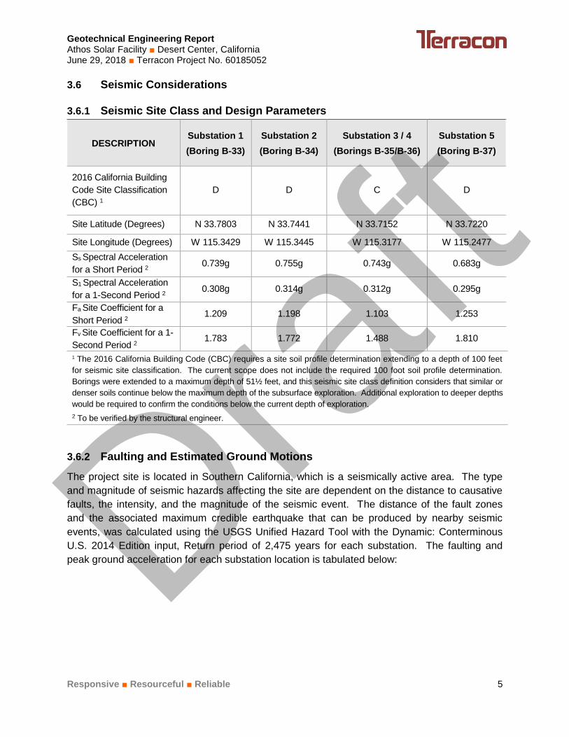
3.6 Seismic Considerations
3.6.1 Seismic Site Class and Design Parameters
DESCRIPTION Substation 1
(Boring B-33)
Substation 2
(Boring B-34)
Substation 3 / 4
(Borings B-35/B-36)
Substation 5
(Boring B-37)
2016 California Building
Code Site Classification
(CBC) 1
D D C D
Site Latitude (Degrees) N 33.7803 N 33.7441 N 33.7152 N 33.7220
Site Longitude (Degrees) W 115.3429 W 115.3445 W 115.3177 W 115.2477
Ss Spectral Acceleration
for a Short Period 2 0.739g 0.755g 0.743g 0.683g
S1 Spectral Acceleration
for a 1-Second Period 2 0.308g 0.314g 0.312g 0.295g
Fa Site Coefficient for a
Short Period 2 1.209 1.198 1.103 1.253
Fv Site Coefficient for a 1-
Second Period 2 1.783 1.772 1.488 1.810
1 The 2016 California Building Code (CBC) requires a site soil profile determination extending to a depth of 100 feet
for seismic site classification. The current scope does not include the required 100 foot soil profile determination.
Borings were extended to a maximum depth of 51½ feet, and this seismic site class definition considers that similar or
denser soils continue below the maximum depth of the subsurface exploration. Additional exploration to deeper depths
would be required to confirm the conditions below the current depth of exploration.
2 To be verified by the structural engineer.
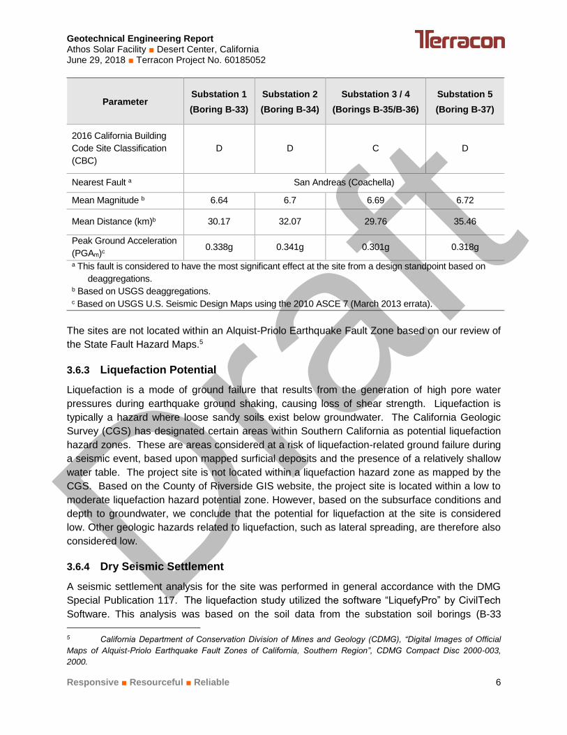
3.6.2 Faulting and Estimated Ground Motions
The project site is located in Southern California, which is a seismically active area. The type
and magnitude of seismic hazards affecting the site are dependent on the distance to causative
faults, the intensity, and the magnitude of the seismic event. The distance of the fault zones
and the associated maximum credible earthquake that can be produced by nearby seismic
events, was calculated using the USGS Unified Hazard Tool with the Dynamic: Conterminous
U.S. 2014 Edition input, Return period of 2,475 years for each substation. The faulting and
peak ground acceleration for each substation location is tabulated below:
Draft
Geotechnical Engineering Report Athos Solar Facility ■ Desert Center, California June 29, 2018 ■ Terracon Project No. 60185052
Responsive ■ Resourceful ■ Reliable 6
Parameter Substation 1
(Boring B-33)
Substation 2
(Boring B-34)
Substation 3 / 4
(Borings B-35/B-36)
Substation 5
(Boring B-37)
2016 California Building
Code Site Classification
(CBC)
D D C D
Nearest Fault a San Andreas (Coachella)
Mean Magnitude b 6.64 6.7 6.69 6.72
Mean Distance (km)b 30.17 32.07 29.76 35.46
Peak Ground Acceleration
(PGAm)c 0.338g 0.341g 0.301g 0.318g
a This fault is considered to have the most significant effect at the site from a design standpoint based on
deaggregations. b Based on USGS deaggregations. c Based on USGS U.S. Seismic Design Maps using the 2010 ASCE 7 (March 2013 errata).
The sites are not located within an Alquist-Priolo Earthquake Fault Zone based on our review of
the State Fault Hazard Maps.5
3.6.3 Liquefaction Potential
Liquefaction is a mode of ground failure that results from the generation of high pore water
pressures during earthquake ground shaking, causing loss of shear strength. Liquefaction is
typically a hazard where loose sandy soils exist below groundwater. The California Geologic
Survey (CGS) has designated certain areas within Southern California as potential liquefaction
hazard zones. These are areas considered at a risk of liquefaction-related ground failure during
a seismic event, based upon mapped surficial deposits and the presence of a relatively shallow
water table. The project site is not located within a liquefaction hazard zone as mapped by the
CGS. Based on the County of Riverside GIS website, the project site is located within a low to
moderate liquefaction hazard potential zone. However, based on the subsurface conditions and
depth to groundwater, we conclude that the potential for liquefaction at the site is considered
low. Other geologic hazards related to liquefaction, such as lateral spreading, are therefore also
considered low.
3.6.4 Dry Seismic Settlement
A seismic settlement analysis for the site was performed in general accordance with the DMG
Special Publication 117. The liquefaction study utilized the software “LiquefyPro” by CivilTech
Software. This analysis was based on the soil data from the substation soil borings (B-33
5 California Department of Conservation Division of Mines and Geology (CDMG), “Digital Images of Official
Maps of Alquist-Priolo Earthquake Fault Zones of California, Southern Region”, CDMG Compact Disc 2000-003,
2000.
Draft
Geotechnical Engineering Report Athos Solar Facility ■ Desert Center, California June 29, 2018 ■ Terracon Project No. 60185052
Responsive ■ Resourceful ■ Reliable 7
through B-37). A PGA of 0.301g to 0.341g and the mean magnitude of 6.64 to 6.72 for the
project site was used. Calculations utilized the depth of groundwater at 70 feet bgs. Settlement
analysis used the Tokimatsu M-Correction method. Fines were corrected for liquefaction using
the Olson and Stark method.
Seismically induced settlement was calculated from a depth of 0 to 50 feet below the ground
surface. Based on the calculation results, total and differential settlement for dry sands is
estimated to be less than ¼ inch.
3.7 Corrosion Potential
Results of soluble sulfate testing indicate that ASTM Type I/II portland cement may be used for
concrete on and below grade for construction of foundations and other elements onsite.
Foundation concrete should be designed for negligible sulfate exposure Class S0 in accordance
with the provisions of the ACI Design Manual, Section 318, Chapter 19.
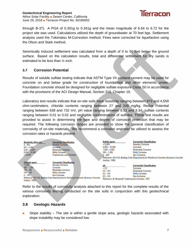
Laboratory test results indicate that on-site soils have resistivity ranging between 873 and 4,559
ohm-centimeters, chloride contents ranging between 27 and 248 mg/kg, Redox Potential
ranging between 638 and 732 mV, pH value ranging between 8.51 and 9.34, sulfate contents
ranging between 0.01 to 0.02 and negligible concentrations of sulfides. These test results are
provided to assist in determining the type and degree of corrosion protection that may be
required. The following corrosion ranges are provided to show the general classification of
corrosivity of on-site materials. We recommend a corrosion engineer be utilized to assess the
corrosion rates or hazards present.
Refer to the results of corrosivity analysis attached to this report for the complete results of the
various corrosivity testing conducted on the site soils in conjunction with this geotechnical
exploration.
3.8 Geologic Hazards
Slope stability – The site is within a gentle slope area, geologic hazards associated with
slope instability may be considered low.
Draft
Geotechnical Engineering Report Athos Solar Facility ■ Desert Center, California June 29, 2018 ■ Terracon Project No. 60185052
Responsive ■ Resourceful ■ Reliable 8
Rock fall hazards - The site is within a gentle slope area, rock fall hazards may be
considered low.
Landslide hazards – The site is within a gentle slope area, landslide hazards may be
considered low.
Surface fault rupture - The site is not located within an Alquist-Priolo Special Study Zone or
a fault zone based on the County of San Bernardino.
Fissures - The site is not within an Alquist-Priolo Special Study Zone nor within a
liquefaction zone. Therefore, the expectation of fissures occurring at the site is considered
low.
Liquefaction potential – The site is mapped within a low to moderate liquefaction zone by
Riverside County. Based on the anticipated depth to groundwater and subsurface
conditions encountered on-site, we conclude that the potential for liquefaction at the site is
considered low.
Collapsible and/or expansive soils – the laboratory test results indicate that the materials at
a depth of approximately 2½ feet bgs exhibit a moderate collapse potential when saturated
under a confining pressure of 2,000 psf. However, based on the in-situ dry density of the
sample and the relatively granular nature of the soils, it is our opinion that this sample was
slightly disturbed. Onsite soils are not considered expansive due to their non-plastic nature.
Subsidence –Based on the County of Riverside GIS system, the site is located within an
area susceptible to subsidence.
Ground shaking potential - The site is not located with an Alquist-Priolo Fault Zone.
However, with the active faults in the region, the site could be subjected to strong ground
shaking that may result from earthquakes on local to distant sources during the life span of
the project.
Seismic Settlement – Based on subsurface conditions and our analysis, we anticipate
seismic induced settlement at the site to be considered low.
Draft