advances in geosynthetics materials and applications for ... · pdf fileadvances in...
TRANSCRIPT
Advances in Geosynthetics Materials
and Applications for Soil Reinforcement
and Environmental Protection Works
Ennio M. Palmeira Professor, University of Brasília, Brasília, Brazil
Fumio Tatsuoka Tokyo University of Science, Tokyo, Japan
Richard J. Bathurst Professor, Royal Military College of Canada, Kingston, Canada
Peter E. Stevenson Consulting Engineer, USA
Jorge G. Zornberg Professor, University of Texas at Austin, Austin, USA
ABSTRACT
Geosynthetics have become well established construction materials for geotechnical and
environmental applications in most parts of the world. Because they constitute manufactured
materials, new products and applications are developed on a routine basis to provide solutions to
routine and critical problems alike. Results from recent research and from monitoring of
instrumented structures throughout the years have led to new design methods for different
applications of geosynthetics. Because of the significant breath of geosynthetic applications, this
paper focuses on recent advances on geosynthetics products, applications and design
methodologies for reinforced soil and environmental protection works.
INTRODUCTION
Geosynthetics have been increasingly used in geotechnical and environmental engineering for the
last 4 decades. Over the years, these products have helped designers and contractors to solve several
types of engineering problems where the use of conventional construction materials would be
restricted or considerably more expensive. There is a significant number of geosynthetic types and
geosynthetic applications in geotechnical and environmental engineering. Due to space limitations,
Bouquet 08 2
this paper will examine the advances on the use of these materials in reinforcement and in
environmental protection.
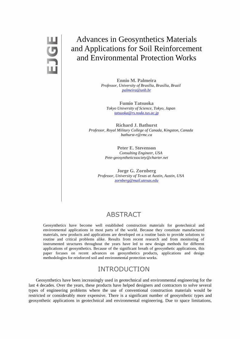
Common types of geosynthetics used for soil reinforcement include geotextiles (particularly
woven geotextiles), geogrids and geocells. Geotextiles (Figure 1a, Bathurst 2007) are continuous
sheets of woven, nonwoven, knitted or stitch-bonded fibers or yarns. The sheets are flexible and
permeable and generally have the appearance of a fabric. Geogrids have a uniformly distributed array
of apertures between their longitudinal and transverse elements. These apertures allow direct contact
between soil particles on either side of the sheet. Geocells are relatively thick, three-dimensional
networks constructed from strips of polymeric sheet. The strips are joined together to form
interconnected cells that are infilled with soil and sometimes concrete. In some cases 0.5 m to 1 m
wide strips of polyolefin geogrids have been linked together with vertical polymeric rods used to form
deep geocell layers called geomattresses.
soil confinement
(a) Geotextiles (b) Geogrids (c) Geocells
Figure 1: Geosynthetics commonly used for soil reinforcement (Bathurst 2007)
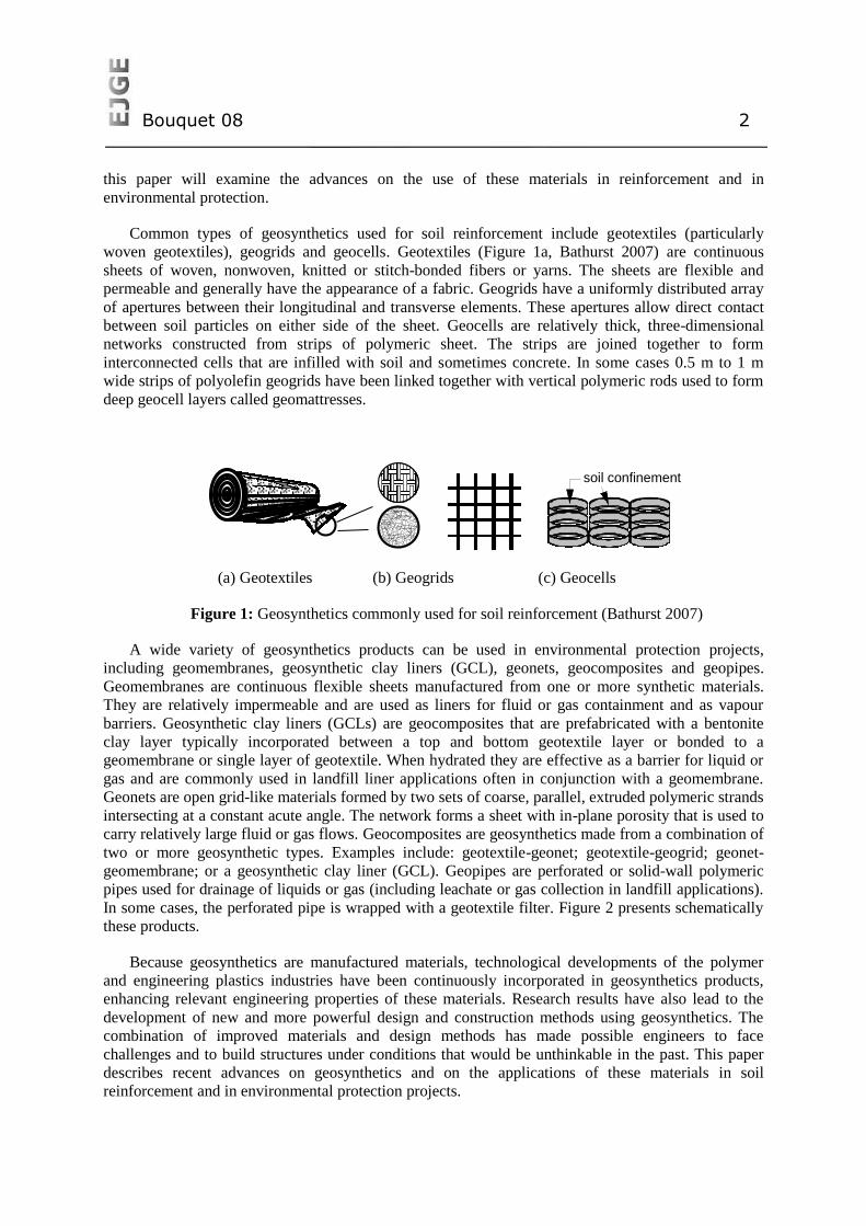
A wide variety of geosynthetics products can be used in environmental protection projects,
including geomembranes, geosynthetic clay liners (GCL), geonets, geocomposites and geopipes.
Geomembranes are continuous flexible sheets manufactured from one or more synthetic materials.
They are relatively impermeable and are used as liners for fluid or gas containment and as vapour
barriers. Geosynthetic clay liners (GCLs) are geocomposites that are prefabricated with a bentonite
clay layer typically incorporated between a top and bottom geotextile layer or bonded to a
geomembrane or single layer of geotextile. When hydrated they are effective as a barrier for liquid or
gas and are commonly used in landfill liner applications often in conjunction with a geomembrane.
Geonets are open grid-like materials formed by two sets of coarse, parallel, extruded polymeric strands
intersecting at a constant acute angle. The network forms a sheet with in-plane porosity that is used to
carry relatively large fluid or gas flows. Geocomposites are geosynthetics made from a combination of
two or more geosynthetic types. Examples include: geotextile-geonet; geotextile-geogrid; geonet-
geomembrane; or a geosynthetic clay liner (GCL). Geopipes are perforated or solid-wall polymeric
pipes used for drainage of liquids or gas (including leachate or gas collection in landfill applications).
In some cases, the perforated pipe is wrapped with a geotextile filter. Figure 2 presents schematically
these products.
Because geosynthetics are manufactured materials, technological developments of the polymer
and engineering plastics industries have been continuously incorporated in geosynthetics products,
enhancing relevant engineering properties of these materials. Research results have also lead to the
development of new and more powerful design and construction methods using geosynthetics. The
combination of improved materials and design methods has made possible engineers to face
challenges and to build structures under conditions that would be unthinkable in the past. This paper
describes recent advances on geosynthetics and on the applications of these materials in soil
reinforcement and in environmental protection projects.
Bouquet 08 3
geotextile
bentonite
(a) Geomembrane (b) GCL (c) Geopipe
geomembrane
geotextile
(c) Geonet (d) Geocomposite
Figure 2: Schematic view of some typical geosynthetics used in environmental protection works
(Bathurst 2007).
DEVELOPMENTS IN GEOSYNTHETICS MATERIALS
TYPES AND APPLICATIONS
The axiom that there is nothing new under the sun regarding geosynthetics is simultaneously true
and totally false. The truth is that the geotechnical problems that engineers use geosynthetics to solve
are timeless: erosion, slope failure, poor bearing capacity etc. The products used to solve these
problems could also be described as timeless as they derive from textile manufacturing techniques that
date into antiquity. The falseness of this premise is revealed by the incremental advancements in the
creation of geosynthetic solutions in the form of both product and geotechnical design. But what are
the areas of incremental improvement in soil reinforcement and environmental applications? As the
following capsules illustrate there is no end in sight for innovative application of geosynthetics.
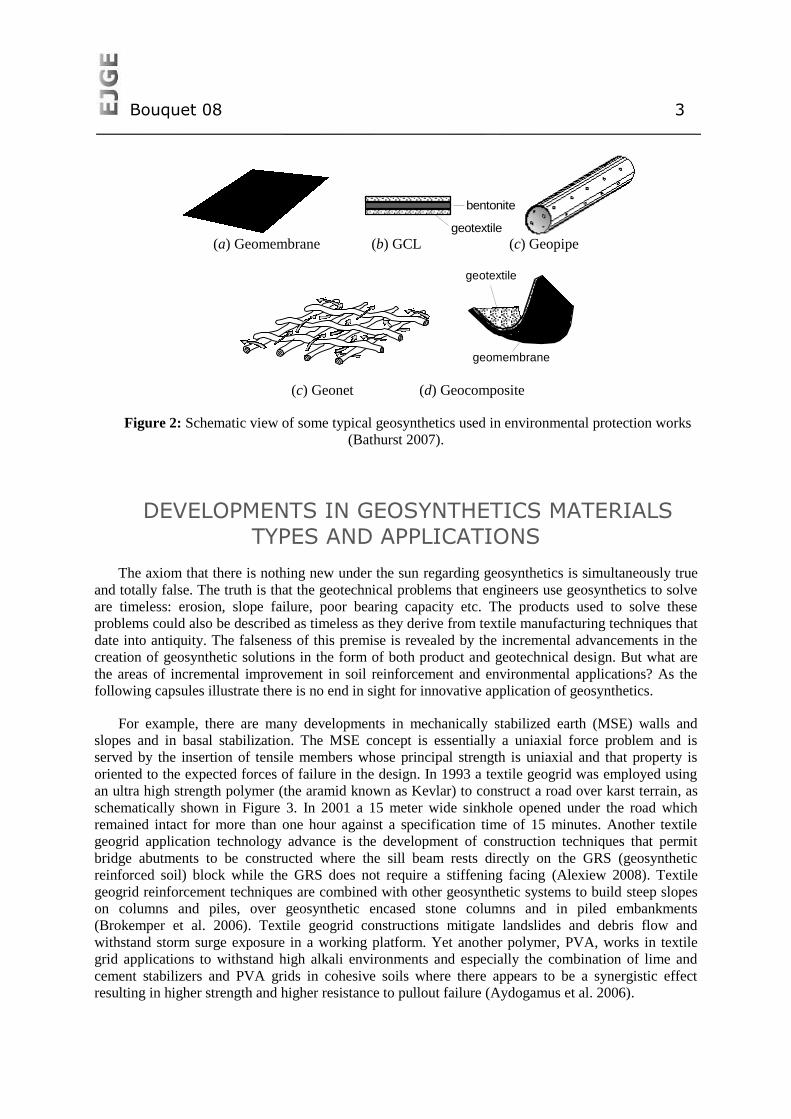
For example, there are many developments in mechanically stabilized earth (MSE) walls and
slopes and in basal stabilization. The MSE concept is essentially a uniaxial force problem and is
served by the insertion of tensile members whose principal strength is uniaxial and that property is
oriented to the expected forces of failure in the design. In 1993 a textile geogrid was employed using
an ultra high strength polymer (the aramid known as Kevlar) to construct a road over karst terrain, as
schematically shown in Figure 3. In 2001 a 15 meter wide sinkhole opened under the road which
remained intact for more than one hour against a specification time of 15 minutes. Another textile
geogrid application technology advance is the development of construction techniques that permit
bridge abutments to be constructed where the sill beam rests directly on the GRS (geosynthetic
reinforced soil) block while the GRS does not require a stiffening facing (Alexiew 2008). Textile
geogrid reinforcement techniques are combined with other geosynthetic systems to build steep slopes
on columns and piles, over geosynthetic encased stone columns and in piled embankments
(Brokemper et al. 2006). Textile geogrid constructions mitigate landslides and debris flow and
withstand storm surge exposure in a working platform. Yet another polymer, PVA, works in textile
grid applications to withstand high alkali environments and especially the combination of lime and
cement stabilizers and PVA grids in cohesive soils where there appears to be a synergistic effect
resulting in higher strength and higher resistance to pullout failure (Aydogamus et al. 2006).
Bouquet 08 4
Figure 3: Reinforced embankment on unstable foundation soil.
Rigid grids have also experienced innovation with the development of new punching patterns that
yield triangular shaped apertures after the stretching process. The new shape has several benefits in
the product profile, rib thickness and in plane stiffness and this three dimensional structure is expected
to offer improvement in confinement which will yield improved rut resistance and better load
distribution (Tensar International 2008).
Soil reinforcement has seen the entry of a third type of geogrid, welded strapping (also described
as strips or bars), which is rigid in structure. Produced in both polyester and polypropylene, the welded
strapping grid is used in both uniaxial and biaxial applications. Properties of interest are strong
junctions, excellent creep characteristics in the polyester form, and high chemical resistance. In the
biaxial form two bars are employed in the cross machine direction giving a three dimensional structure
to aid in confinement applications (Elias 2000).
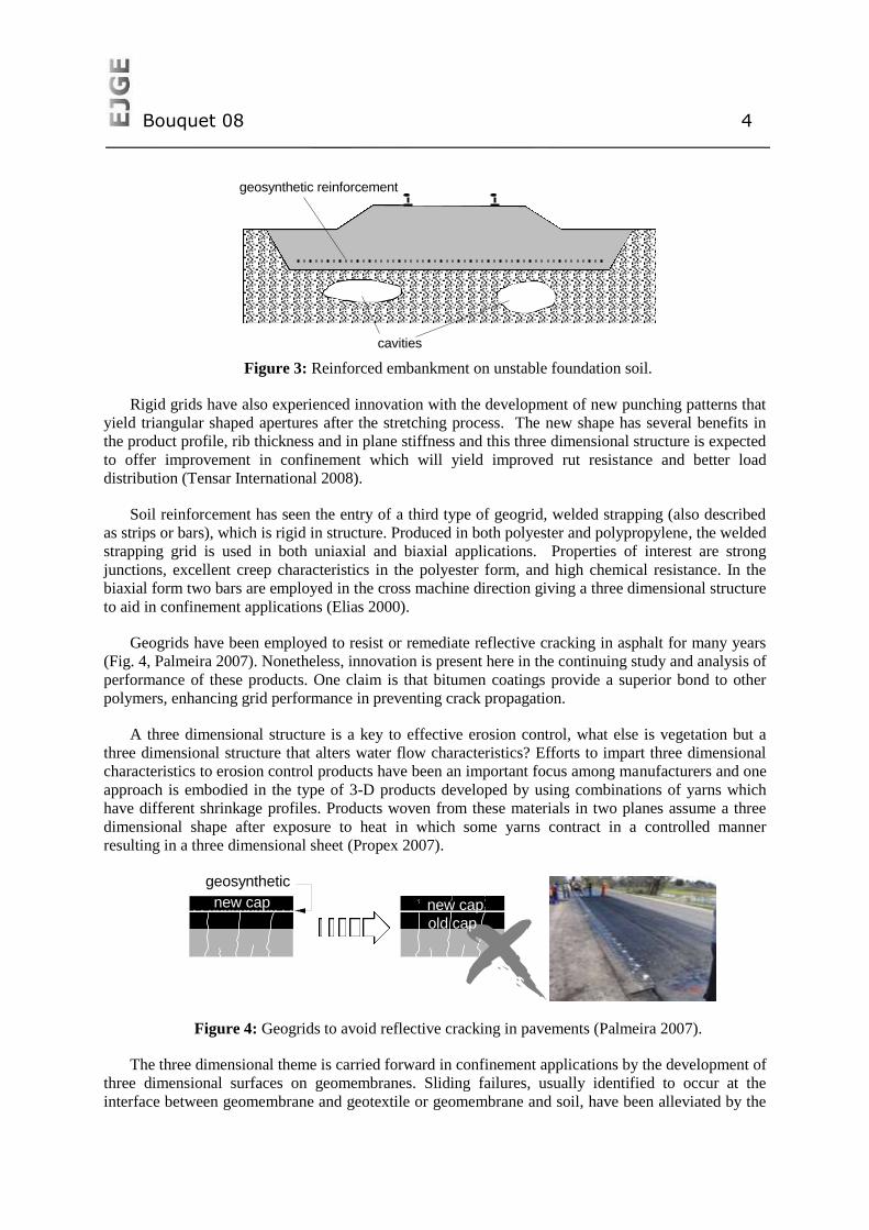
Geogrids have been employed to resist or remediate reflective cracking in asphalt for many years
(Fig. 4, Palmeira 2007). Nonetheless, innovation is present here in the continuing study and analysis of
performance of these products. One claim is that bitumen coatings provide a superior bond to other
polymers, enhancing grid performance in preventing crack propagation.
A three dimensional structure is a key to effective erosion control, what else is vegetation but a
three dimensional structure that alters water flow characteristics? Efforts to impart three dimensional
characteristics to erosion control products have been an important focus among manufacturers and one
approach is embodied in the type of 3-D products developed by using combinations of yarns which
have different shrinkage profiles. Products woven from these materials in two planes assume a three
dimensional shape after exposure to heat in which some yarns contract in a controlled manner
resulting in a three dimensional sheet (Propex 2007).
Figure 4: Geogrids to avoid reflective cracking in pavements (Palmeira 2007).
The three dimensional theme is carried forward in confinement applications by the development of
three dimensional surfaces on geomembranes. Sliding failures, usually identified to occur at the
interface between geomembrane and geotextile or geomembrane and soil, have been alleviated by the
geosynthetic reinforcement
cavities
new capnew cap
geosynthetic
old cap
Bouquet 08 5
development of textured and embossed surfaces on geomembranes. Three dimensioned
geomembranes, embossed surfaces for example, have consistent thickness, consistent asperity height
and consistent properties and are easy to install and, most important, result in improved performance
(better adhesion, better resistance to sliding) (Frobel 1996).
Electrokinetics and electroosmosis are techniques employed in manipulating pore pressure and
plasticity indices of soils. Formerly hampered by difficulty in establishing suitable electrodes in soil
structures, electrokinetics and eleectroosmosis are becoming viable technologies for soil reinforcement
and environmental rehabilitation and geosynthetics are one of the means of introducing anodes and
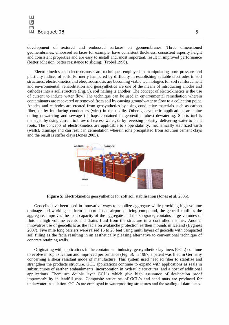
cathodes into a soil structure (Fig. 5), soil nailing is another. The concept of electrokinetics is the use
of current to induce water flow. The technique can be used in environmental remediation wherein
contaminants are recovered or removed from soil by causing groundwater to flow to a collection point.
Anodes and cathodes are created from geosynthetics by using conductive materials such as carbon
fiber, or by interlacing conductors (wire) in the textile. Other geosynthetic applications are mine
tailing dewatering and sewage (perhaps contained in geotextile tubes) dewatering. Sports turf is
managed by using current to draw off excess water, or by reversing polarity, delivering water to plant
roots. The concepts of electrokinetics are applicable to slope stability, mechanically stabilized earth
(walls), drainage and can result in cementation wherein ions precipitated from solution cement clays
and the result is stiffer clays (Jones 2005).
Figure 5: Electrokinetics geosynthetics for soft soil stabilisation (Jones et al. 2005).
Geocells have been used in innovative ways to stabilize aggregate while providing high volume
drainage and working platform support. In an airport de-icing compound, the geocell confines the
aggregate, improves the load capacity of the aggregate and the subgrade, contains large volumes of
fluid in high volume events and drains fluid from the structure in a controlled manner. Another
innovative use of geocells is as the facia on avalanche protection earthen mounds in Iceland (Bygness
2007). Five mile long barriers were raised 15 to 20 feet using multi layers of geocells with compacted
soil filling as the facia resulting in an aesthetically pleasing alternative to conventional technique of
concrete retaining walls.
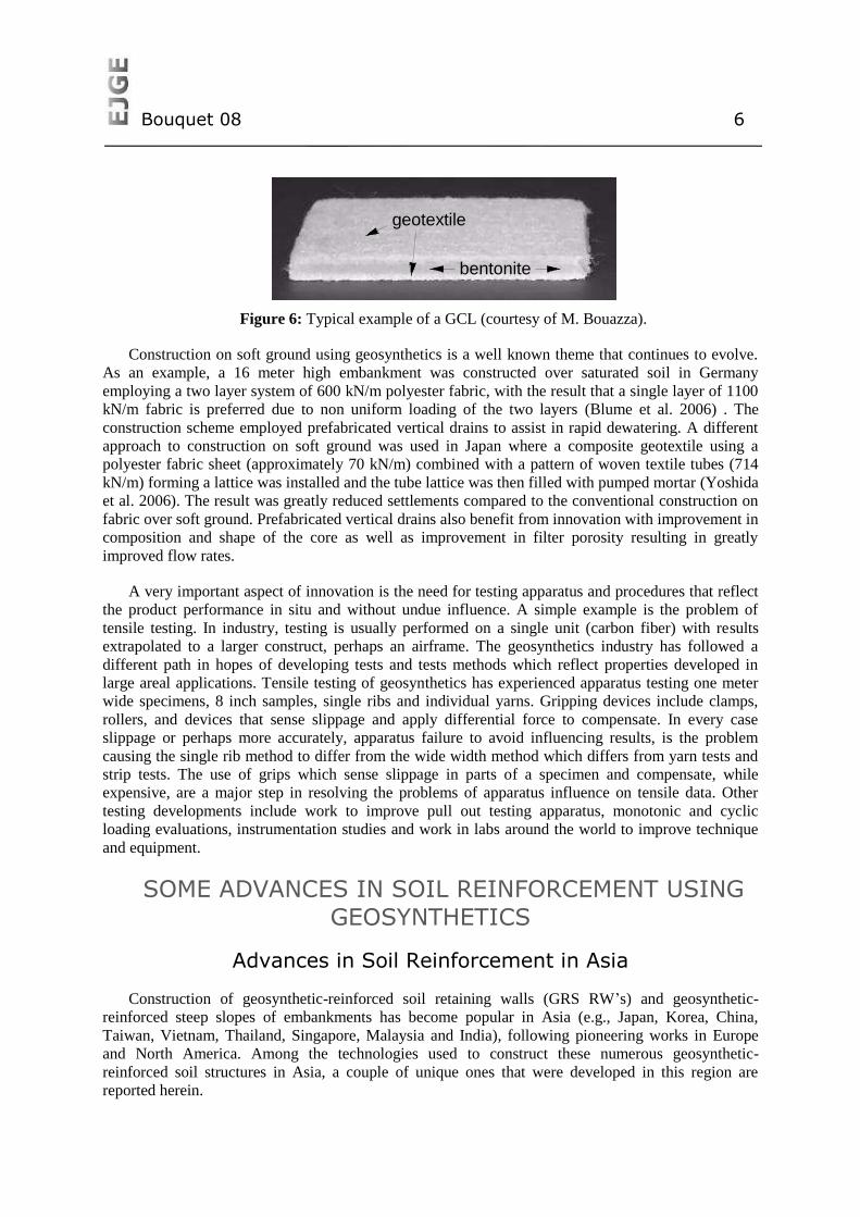
Originating with applications in the containment industry, geosynthetic clay liners (GCL) continue
to evolve in sophistication and improved performance (Fig. 6). In 1987, a patent was filed in Germany
concerning a shear resistant mode of manufacture. This system used needled fiber to stabilize and
strengthen the products structure. GCL applications continue to expand with applications as seals in
substructures of earthen embankments, incorporation in hydraulic structures, and a host of additional
applications. There are double layer GCL’s which give high assurance of desiccation proof
impermeability in landfill caps. Composite structures of GCL’s and sand mats are produced for
underwater installation. GCL’s are employed in waterproofing structures and the sealing of dam faces.
Bouquet 08 6
Figure 6: Typical example of a GCL (courtesy of M. Bouazza).
Construction on soft ground using geosynthetics is a well known theme that continues to evolve.
As an example, a 16 meter high embankment was constructed over saturated soil in Germany
employing a two layer system of 600 kN/m polyester fabric, with the result that a single layer of 1100
kN/m fabric is preferred due to non uniform loading of the two layers (Blume et al. 2006) . The
construction scheme employed prefabricated vertical drains to assist in rapid dewatering. A different
approach to construction on soft ground was used in Japan where a composite geotextile using a
polyester fabric sheet (approximately 70 kN/m) combined with a pattern of woven textile tubes (714
kN/m) forming a lattice was installed and the tube lattice was then filled with pumped mortar (Yoshida
et al. 2006). The result was greatly reduced settlements compared to the conventional construction on
fabric over soft ground. Prefabricated vertical drains also benefit from innovation with improvement in
composition and shape of the core as well as improvement in filter porosity resulting in greatly
improved flow rates.
A very important aspect of innovation is the need for testing apparatus and procedures that reflect
the product performance in situ and without undue influence. A simple example is the problem of
tensile testing. In industry, testing is usually performed on a single unit (carbon fiber) with results
extrapolated to a larger construct, perhaps an airframe. The geosynthetics industry has followed a
different path in hopes of developing tests and tests methods which reflect properties developed in
large areal applications. Tensile testing of geosynthetics has experienced apparatus testing one meter
wide specimens, 8 inch samples, single ribs and individual yarns. Gripping devices include clamps,
rollers, and devices that sense slippage and apply differential force to compensate. In every case
slippage or perhaps more accurately, apparatus failure to avoid influencing results, is the problem
causing the single rib method to differ from the wide width method which differs from yarn tests and
strip tests. The use of grips which sense slippage in parts of a specimen and compensate, while
expensive, are a major step in resolving the problems of apparatus influence on tensile data. Other
testing developments include work to improve pull out testing apparatus, monotonic and cyclic
loading evaluations, instrumentation studies and work in labs around the world to improve technique
and equipment.
SOME ADVANCES IN SOIL REINFORCEMENT USING
GEOSYNTHETICS
Advances in Soil Reinforcement in Asia
Construction of geosynthetic-reinforced soil retaining walls (GRS RW’s) and geosynthetic-
reinforced steep slopes of embankments has become popular in Asia (e.g., Japan, Korea, China,
Taiwan, Vietnam, Thailand, Singapore, Malaysia and India), following pioneering works in Europe
and North America. Among the technologies used to construct these numerous geosynthetic-
reinforced soil structures in Asia, a couple of unique ones that were developed in this region are
reported herein.
geotextile
bentonite
Bouquet 08 7
GRS RWs Having a Full-Height Rigid Facing
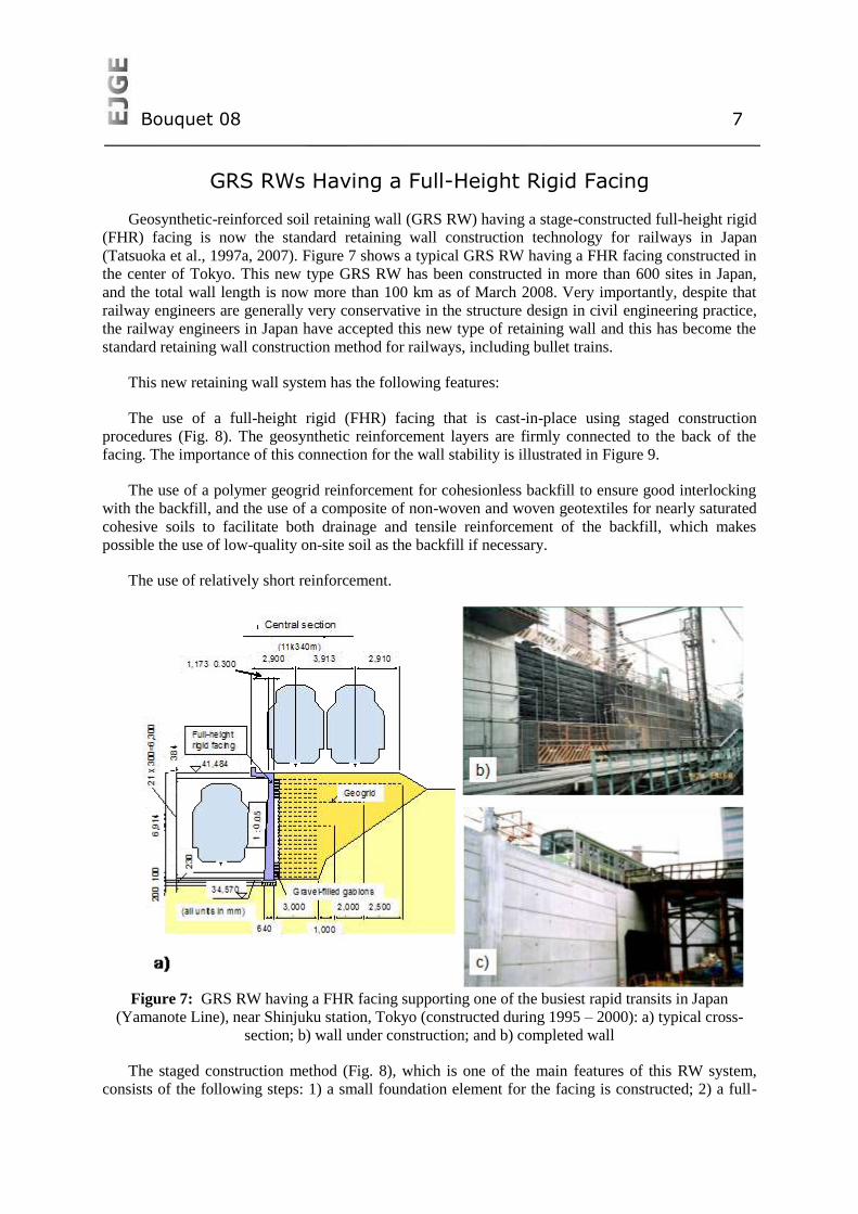
Geosynthetic-reinforced soil retaining wall (GRS RW) having a stage-constructed full-height rigid
(FHR) facing is now the standard retaining wall construction technology for railways in Japan
(Tatsuoka et al., 1997a, 2007). Figure 7 shows a typical GRS RW having a FHR facing constructed in
the center of Tokyo. This new type GRS RW has been constructed in more than 600 sites in Japan,
and the total wall length is now more than 100 km as of March 2008. Very importantly, despite that
railway engineers are generally very conservative in the structure design in civil engineering practice,
the railway engineers in Japan have accepted this new type of retaining wall and this has become the
standard retaining wall construction method for railways, including bullet trains.
This new retaining wall system has the following features:
The use of a full-height rigid (FHR) facing that is cast-in-place using staged construction
procedures (Fig. 8). The geosynthetic reinforcement layers are firmly connected to the back of the
facing. The importance of this connection for the wall stability is illustrated in Figure 9.
The use of a polymer geogrid reinforcement for cohesionless backfill to ensure good interlocking
with the backfill, and the use of a composite of non-woven and woven geotextiles for nearly saturated
cohesive soils to facilitate both drainage and tensile reinforcement of the backfill, which makes
possible the use of low-quality on-site soil as the backfill if necessary.
The use of relatively short reinforcement.
Figure 7: GRS RW having a FHR facing supporting one of the busiest rapid transits in Japan
(Yamanote Line), near Shinjuku station, Tokyo (constructed during 1995 – 2000): a) typical cross-
section; b) wall under construction; and b) completed wall
The staged construction method (Fig. 8), which is one of the main features of this RW system,
consists of the following steps: 1) a small foundation element for the facing is constructed; 2) a full-
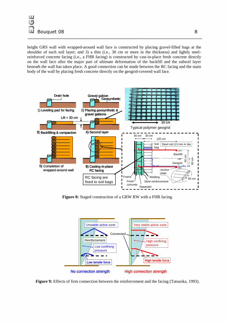
Bouquet 08 8
height GRS wall with wrapped-around wall face is constructed by placing gravel-filled bags at the
shoulder of each soil layer; and 3) a thin (i.e., 30 cm or more in the thickness) and lightly steel-
reinforced concrete facing (i.e., a FHR facing) is constructed by cast-in-place fresh concrete directly
on the wall face after the major part of ultimate deformation of the backfill and the subsoil layer
beneath the wall has taken place. A good connection can be made between the RC facing and the main
body of the wall by placing fresh concrete directly on the geogrid-covered wall face.
Figure 8: Staged construction of a GRW RW with a FHR facing.
Figure 9: Effects of firm connection between the reinforcement and the facing (Tatsuoka, 1993).
5)5) Completion of
wrapped-around wall
4)4) Second layer3)3) Backfilling & compaction
2) Placing geosynthetic &
gravel gabions
Gravel gabionGeosynthetic
1) Leveling pad for facing
Drain hole
6)6) Casting-in-place
RC facing
Typical polymer geogrid
10 cm
Lift = 30 cm
RC facing are
fixed to soil bags
鉄製のアンカー(直径13 mm)
30 cm 30 cm120 cm
30 c
m
60 c
m
Backfill
Geogrid
Frame
Fresh
concreteSeparator
Steel reinforcement
Welding
Anchor
plate
60 cm
Soil
bagSteel rod (13 mm in dia.)鉄製のアンカー(直径13 mm)
30 cm 30 cm120 cm
30 c
m
60 c
m
Backfill
Geogrid
Frame
Fresh
concreteSeparator
Steel reinforcement
Welding
Anchor
plate
60 cm
Soil
bagSteel rod (13 mm in dia.)
5)5) Completion of
wrapped-around wall
4)4) Second layer4)4) Second layer3)3) Backfilling & compaction3)3) Backfilling & compaction
2) Placing geosynthetic &
gravel gabions
Gravel gabionGeosynthetic
2) Placing geosynthetic &
gravel gabions
Gravel gabionGeosynthetic
1) Leveling pad for facing
Drain hole
1) Leveling pad for facing
Drain hole
6)6) Casting-in-place
RC facing
6)6) Casting-in-place
RC facing
Typical polymer geogrid
10 cm
Lift = 30 cm
RC facing are
fixed to soil bags
鉄製のアンカー(直径13 mm)
30 cm 30 cm120 cm
30 c
m
60 c
m
Backfill
Geogrid
Frame
Fresh
concreteSeparator
Steel reinforcement
Welding
Anchor
plate
60 cm
Soil
bagSteel rod (13 mm in dia.)鉄製のアンカー(直径13 mm)
30 cm 30 cm120 cm
30 c
m
60 c
m
Backfill
Geogrid
Frame
Fresh
concreteSeparator
Steel reinforcement
Welding
Anchor
plate
60 cm
Soil
bagSteel rod (13 mm in dia.)
Unstable active zone Very stable active zone
Reinforcement
Connected
No connection strength High connection strength
High tensile forceLow tensile force
High confining
pressureLow confining
pressure
Unstable active zone Very stable active zone
Reinforcement
Connected
No connection strength High connection strength
High tensile forceLow tensile force
High confining
pressureLow confining
pressure
Bouquet 08 9
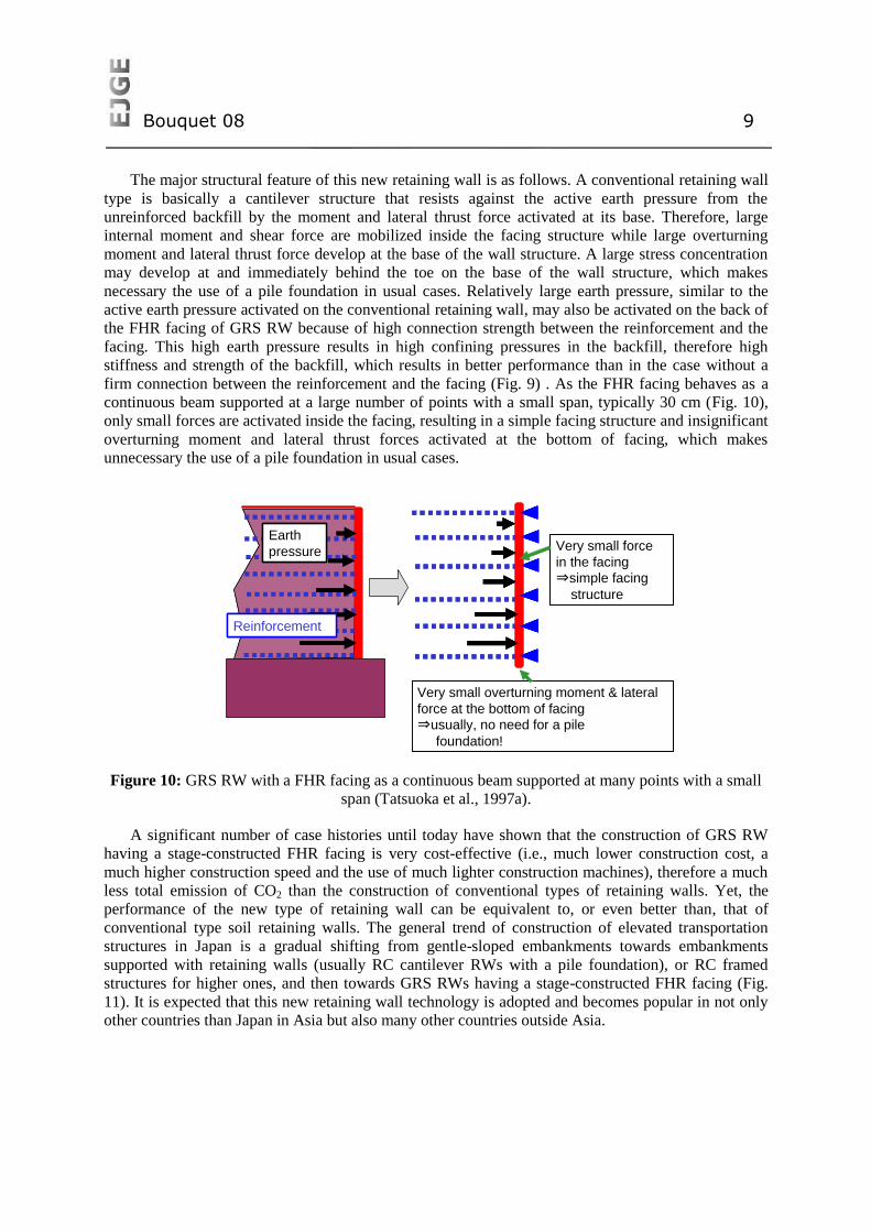
The major structural feature of this new retaining wall is as follows. A conventional retaining wall
type is basically a cantilever structure that resists against the active earth pressure from the
unreinforced backfill by the moment and lateral thrust force activated at its base. Therefore, large
internal moment and shear force are mobilized inside the facing structure while large overturning
moment and lateral thrust force develop at the base of the wall structure. A large stress concentration
may develop at and immediately behind the toe on the base of the wall structure, which makes
necessary the use of a pile foundation in usual cases. Relatively large earth pressure, similar to the
active earth pressure activated on the conventional retaining wall, may also be activated on the back of
the FHR facing of GRS RW because of high connection strength between the reinforcement and the
facing. This high earth pressure results in high confining pressures in the backfill, therefore high
stiffness and strength of the backfill, which results in better performance than in the case without a
firm connection between the reinforcement and the facing (Fig. 9) . As the FHR facing behaves as a
continuous beam supported at a large number of points with a small span, typically 30 cm (Fig. 10),
only small forces are activated inside the facing, resulting in a simple facing structure and insignificant
overturning moment and lateral thrust forces activated at the bottom of facing, which makes
unnecessary the use of a pile foundation in usual cases.
Figure 10: GRS RW with a FHR facing as a continuous beam supported at many points with a small
span (Tatsuoka et al., 1997a).
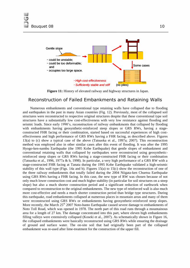
A significant number of case histories until today have shown that the construction of GRS RW
having a stage-constructed FHR facing is very cost-effective (i.e., much lower construction cost, a
much higher construction speed and the use of much lighter construction machines), therefore a much
less total emission of CO2 than the construction of conventional types of retaining walls. Yet, the
performance of the new type of retaining wall can be equivalent to, or even better than, that of
conventional type soil retaining walls. The general trend of construction of elevated transportation
structures in Japan is a gradual shifting from gentle-sloped embankments towards embankments
supported with retaining walls (usually RC cantilever RWs with a pile foundation), or RC framed
structures for higher ones, and then towards GRS RWs having a stage-constructed FHR facing (Fig.
11). It is expected that this new retaining wall technology is adopted and becomes popular in not only
other countries than Japan in Asia but also many other countries outside Asia.
Earth
pressure
Reinforcement
Very small force
in the facing
⇒simple facing
structure
Very small overturning moment & lateral
force at the bottom of facing
⇒usually, no need for a pile
foundation!
Earth
pressure
Reinforcement
Very small force
in the facing
⇒simple facing
structure
Very small overturning moment & lateral
force at the bottom of facing
⇒usually, no need for a pile
foundation!
Bouquet 08 10
Figure 11: History of elevated railway and highway structures in Japan.
Reconstruction of Failed Embankments and Retaining Walls
Numerous embankments and conventional type retaining walls have collapsed due to flooding
and earthquakes in the past in many Asian countries (Fig. 12). Previously, most of the collapsed soil
structures were reconstructed to respective original structures despite that these conventional type soil
structures have a substantially low cost-effectiveness with very low resistance against flooding and
seismic loads. Since early 1990’s, reconstruction of railway embankments that collapsed by flooding
with embankments having geosynthetic-reinforced steep slopes or GRS RWs, having a stage-
constructed FHR facing or their combination, started based on successful experiences of high cost-
effectiveness and high performance of GRS RWs having a FHR facing, as described above. Figures
13(a) to (c) show a typical case of the above (Tatsuoka et al., 1997a; 2007). This reconstruction
method was employed also in other similar cases after this event of flooding. It was after the 1995
Hyogo-ken-nambu Earthquake (the 1995 Kobe Earthquake) that gentle slopes of embankment and
conventional retaining walls that collapsed by earthquakes were reconstructed using geosynthetic-
reinforced steep slopes or GRS RWs having a stage-constructed FHR facing or their combination
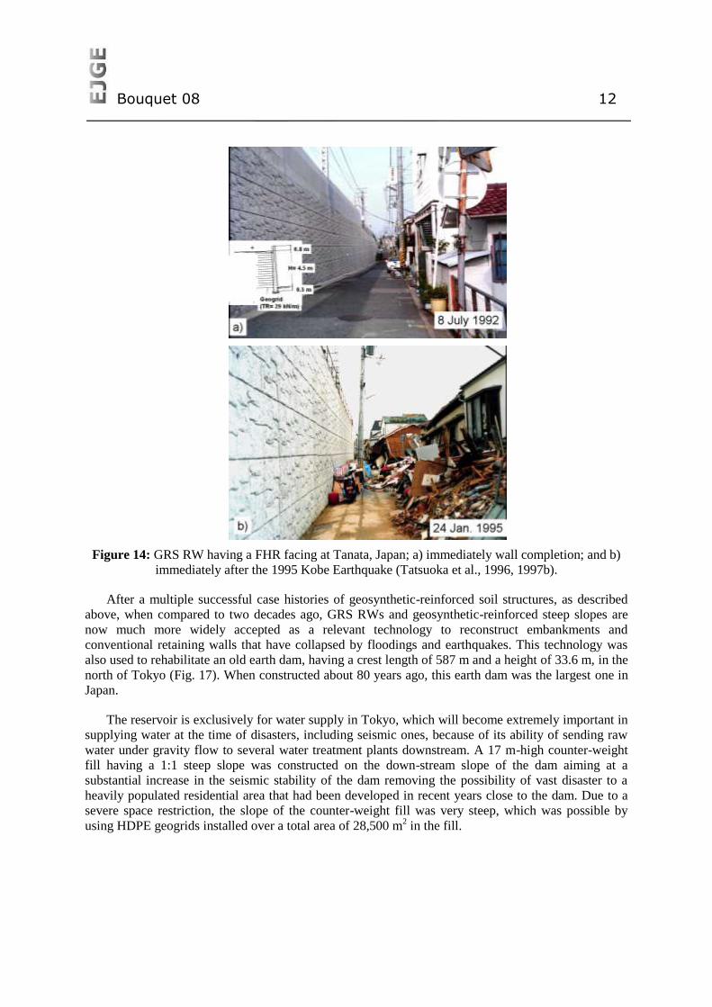
(Tatsuoka et al., 1996, 1977a & b, 1998). In particular, a very high performance of a GRS RW with a
stage-constructed FHR facing at Tanata during the 1995 Kobe Earthquake validated a high-seismic
stability of this wall type (Figs. 14a and b). Figures 15(a) to 15(c) show the reconstruction of one of
the three railway embankments that totally failed during the 2004 Niigata-ken Chuetsu Earthquake
using GRS RWs having a FHR facing. In this case, the new type of RW was chosen because of not
only much lower construction cost and much higher stability (in particular for soil structures on a steep
slope) but also a much shorter construction period and a significant reduction of earthwork when
compared to reconstruction to the original embankments. The new type of reinforced wall is also much
more cost-effective and needs a much shorter construction period than bridge type structures. During
this earthquake, road embankments collapsed at numerous places in mountain areas and many of them
were reconstructed using GRS RWs or embankments having geosynthetic-reinforced steep slopes.
More recently, the March 25th 2007 Noto-hanto Earthquake caused severe damage to embankments of
Noto Toll Road, which was opened in 1978. The north part of this road runs through a mountainous
area for a length of 27 km. The damage concentrated into this part, where eleven high embankments
filling valleys were extensively collapsed (Koseki et al., 2007). As schematically shown in Figure 16,
the collapsed embankments were basically reconstructed using GRS RWs while ensuring the drainage
of ground and surface water. The on-site soil that had originally been part of the collapsed
embankment was re-used after lime-treatment for the construction of the upper fill.
Gentle slope
・could be unstable;
・could be too deformable;
and
・occupies too large space.
Some cases
・High cost-effectiveness
・Sufficiently stable and stiff (no piles)
Gentle slope
・could be unstable;
・could be too deformable;
and
・occupies too large space.
Some cases
・High cost-effectiveness
・Sufficiently stable and stiff (no piles)
Bouquet 08 11
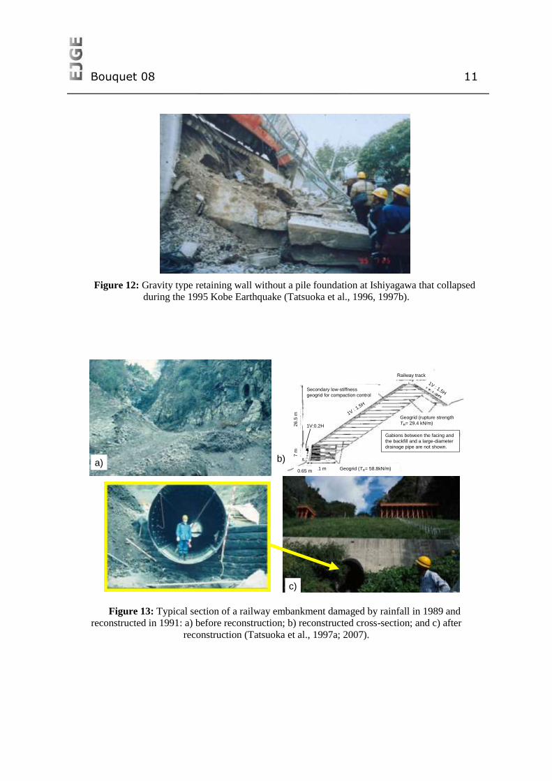
Figure 12: Gravity type retaining wall without a pile foundation at Ishiyagawa that collapsed
during the 1995 Kobe Earthquake (Tatsuoka et al., 1996, 1997b).
Figure 13: Typical section of a railway embankment damaged by rainfall in 1989 and
reconstructed in 1991: a) before reconstruction; b) reconstructed cross-section; and c) after
reconstruction (Tatsuoka et al., 1997a; 2007).
Geogrid (rupture strength
TR= 29.4 kN/m)
Gabions between the facing and
the backfill and a large-diameter
drainage pipe are not shown.
Railway track
1V : 1.5H
1V : 1.5H
Secondary low-stiffness
geogrid for compaction control
Geogrid (TR= 58.8kN/m)11 m0.65 m
7 m
1V:0.2H26
.5 m
a) b)
c)
Geogrid (rupture strength
TR= 29.4 kN/m)
Gabions between the facing and
the backfill and a large-diameter
drainage pipe are not shown.
Railway track
1V : 1.5H
1V : 1.5H
Secondary low-stiffness
geogrid for compaction control
Geogrid (TR= 58.8kN/m)11 m0.65 m
7 m
1V:0.2H26
.5 m
a) b)
c)
Bouquet 08 12
Figure 14: GRS RW having a FHR facing at Tanata, Japan; a) immediately wall completion; and b)
immediately after the 1995 Kobe Earthquake (Tatsuoka et al., 1996, 1997b).
After a multiple successful case histories of geosynthetic-reinforced soil structures, as described
above, when compared to two decades ago, GRS RWs and geosynthetic-reinforced steep slopes are
now much more widely accepted as a relevant technology to reconstruct embankments and
conventional retaining walls that have collapsed by floodings and earthquakes. This technology was
also used to rehabilitate an old earth dam, having a crest length of 587 m and a height of 33.6 m, in the
north of Tokyo (Fig. 17). When constructed about 80 years ago, this earth dam was the largest one in
Japan.
The reservoir is exclusively for water supply in Tokyo, which will become extremely important in
supplying water at the time of disasters, including seismic ones, because of its ability of sending raw
water under gravity flow to several water treatment plants downstream. A 17 m-high counter-weight
fill having a 1:1 steep slope was constructed on the down-stream slope of the dam aiming at a
substantial increase in the seismic stability of the dam removing the possibility of vast disaster to a
heavily populated residential area that had been developed in recent years close to the dam. Due to a
severe space restriction, the slope of the counter-weight fill was very steep, which was possible by
using HDPE geogrids installed over a total area of 28,500 m2 in the fill.
Bouquet 08 13
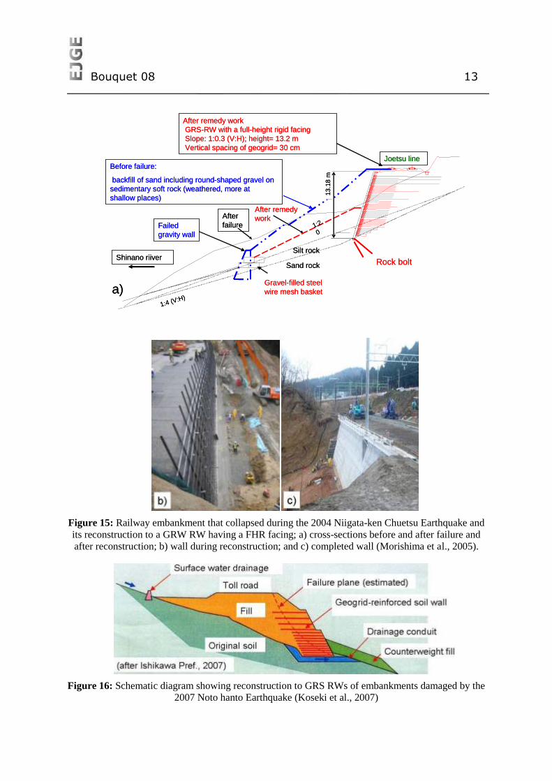
Figure 15: Railway embankment that collapsed during the 2004 Niigata-ken Chuetsu Earthquake and
its reconstruction to a GRW RW having a FHR facing; a) cross-sections before and after failure and
after reconstruction; b) wall during reconstruction; and c) completed wall (Morishima et al., 2005).
Figure 16: Schematic diagram showing reconstruction to GRS RWs of embankments damaged by the
2007 Noto hanto Earthquake (Koseki et al., 2007)
Silt rock
Sand rock
1:2.
0
Before failure:
backfill of sand including round-shaped gravel on
sedimentary soft rock (weathered, more at
shallow places)
13.1
8 m
After
failure
1:4 (V:H)
After remedy
workFailed
gravity wall
Joetsu line
Shinano riiver
After remedy work
GRS-RW with a full-height rigid facing
Slope: 1:0.3 (V:H); height= 13.2 m
Vertical spacing of geogrid= 30 cm
Gravel-filled steel
wire mesh basket
Rock bolt
a)
Bouquet 08 14
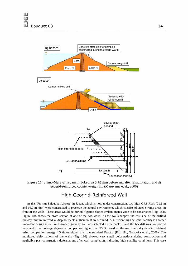
Figure 17: Shimo-Murayama dam in Tokyo: a) & b) dam before and after rehabilitation; and d)
geogrid-reinforced counter-weight fill (Maruyama et al., 2006)
High Geogrid-Reinforced Wall
At the “Fujisan-Shizuoka Airport” in Japan, which is now under construction, two high GRS RWs (21.1 m
and 16.7 m high) were constructed to preserve the natural environment, which consists of steep swamp areas, in
front of the walls. These areas would be buried if gentle-sloped embankments were to be constructed (Fig. 18a).
Figure 18b shows the cross-section of one of the two walls. As the walls support the east side of the airfield
runway, minimum residual displacements at their crest are required. A sufficient high seismic stability is another
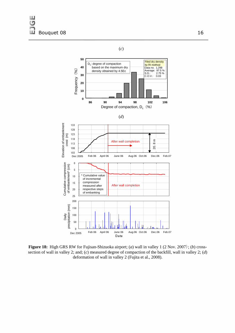
important design issue. Well-graded gravelly soil was selected as the backfill and the backfill was compacted
very well to an average degree of compaction higher than 95 % based on the maximum dry density obtained
using compaction energy 4.5 times higher than the standard Proctor (Fig. 18c; Tatsuoka et al., 2008). The
monitored deformations of the walls (Fig. 18d) showed very small deformations during construction and
negligible post-construction deformations after wall completion, indicating high stability conditions. This case
Core
Earth fill
Counter weight fill
Concrete protection for bombing
constructed during the World War II
Earth fill
a) before
Core
Earth fill
Counter weight fill
Concrete protection for bombing
constructed during the World War II
Earth fill
a) before
Drain
Cement-mixed soil
Geosynthetic-
reinforced fill
b) after
Drain
Cement-mixed soil
Geosynthetic-
reinforced fill
b) after
170
001
120
03
400
16
00
160
01600
16
00
16001
600
160
0
Back filling G.L.
Level drain
Foudation forming
1900
High strength geogrids
Low strength geogrids100
40010
0500
10000
7000G.L. of backfilling
Foundation forming
Low strength
geogrid
High strength geogrid
c)
170
001
120
03
400
16
00
160
01600
16
00
16001
600
160
0
Back filling G.L.
Level drain
Foudation forming
1900
High strength geogrids
Low strength geogrids100
40010
0500
10000
7000G.L. of backfilling
Foundation forming
Low strength
geogrid
High strength geogrid
c)
Bouquet 08 15
history indicates that long-term deformation of geosynthetic-reinforced soil structures can be restrained very
effectively by good compaction of good backfill despite that significantly stiff reinforcement members are not
used.
The recorded time histories of the tensile strain in the geogrid also exhibited nearly no increase after wall
completion. Kongkitkul et al. (2008) analysed these data based on an elasto-viscoplastic constitutive model of
the geogrid developed based on laboratory test results. They showed that the tensile load in the geogrid tends to
decrease with time after wall completion, and creep rupture failure of the geogrid by the end of the wall design
life is unlikely. The reduction of the tensile strain in the geogrid with time is due to not only the viscous
properties of the geogrid but also because of compressive creep strains in the horizontal direction of the backfill
caused by the tensile force in the reinforcement. This result indicates that the assumption in current practice that
the tensile load mobilised in the geosynthetic reinforcement in the backfill is kept constant over-estimates the
possibility of creep rupture failure of geosynthetic reinforcement. In fact, the rupture strength of geosynthetic-
reinforcement used in the seismic design of GRS-RWs having a stage-constructed FHR facing is not reduced for
creep rupture. Tatsuoka et al. (2006) proposed a new method by which the design rupture strength of the
geosynthetic reinforcement to be used in both seismic and static designs of GRS RWs is not reduced for creep
rupture.
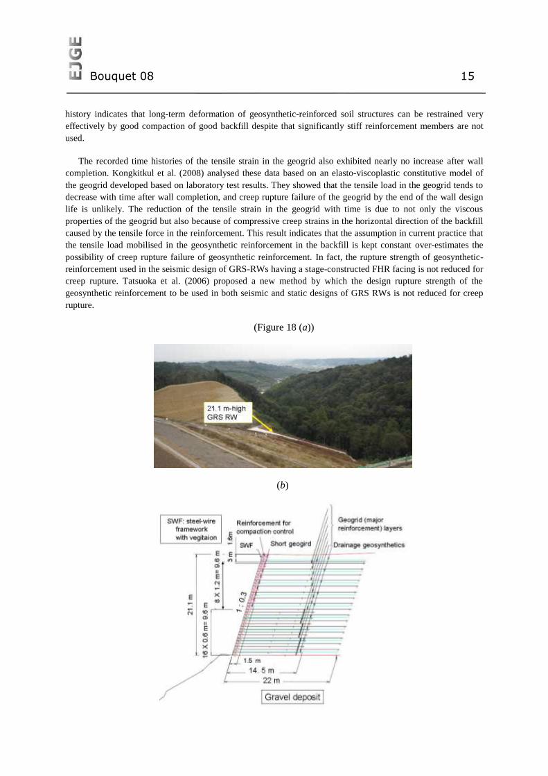
(Figure 18 (a))
(b)
Bouquet 08 16
(c)
(d)
Figure 18: High GRS RW for Fujisan-Shizuoka airport; (a) wall in valley 1 (2 Nov. 2007); (b) cross-
section of wall in valley 2; and; (c) measured degree of compaction of the backfill, wall in valley 2; (d)
deformation of wall in valley 2 (Fujita et al., 2008).
実際の分布(推定)→
0
10
20
30
40
50
86 90 94 98 102 106
Degree of compaction, Dc(%)
Fre
qu
ency(
%)
Filed dry density
by RI methodData no. 1,298Average: 97.5 %S.D.: 2.75 %C.O.V.: 0.03
Dc: degree of compaction
based on the maximum dry
density obtained by 4.5Ec
実際の分布(推定)→
0
10
20
30
40
50
86 90 94 98 102 106
Degree of compaction, Dc(%)
Fre
qu
ency(
%)
Filed dry density
by RI methodData no. 1,298Average: 97.5 %S.D.: 2.75 %C.O.V.: 0.03
Dc: degree of compaction
based on the maximum dry
density obtained by 4.5Ec
0
5
10
15
20
25
累計
圧縮
量(
cm)
盛土完了
層別沈下計
103
108
113
118
123
128
133
H17.12 H18.2 H18.4 H18.6 H18.8 H18.10 H18.12 H19.2
盛土
標高
(m)
20.8m盛土完了
0
50
100
150
200
H17.12 H18.2 H18.4 H18.6 H18.8 H18.10 H18.12 H19.2
日付(日)
降水
量(mm)
Ele
va
tio
n o
f e
mba
nkm
en
t
cre
st (
m)
Cu
mu
lative
co
mpre
ssio
n
of e
mb
an
km
ent*
(cm
)D
aily
pre
cip
itatio
n (
mm
)
Date
20. 8
m
After wall completion
After wall completion
* Cumulative value
of incremental
compression
measured after
respective steps
of embanking
Dec 2005
Dec 2005
Feb 06 April 06 June 06 Aug.06 Oct.06 Dec.06 Feb.07
Feb 06Feb 06 April 06 June 06 Aug.06 Oct.06 Dec.06 Feb.07
0
5
10
15
20
25
累計
圧縮
量(
cm)
盛土完了
層別沈下計
103
108
113
118
123
128
133
H17.12 H18.2 H18.4 H18.6 H18.8 H18.10 H18.12 H19.2
盛土
標高
(m)
20.8m盛土完了
0
50
100
150
200
H17.12 H18.2 H18.4 H18.6 H18.8 H18.10 H18.12 H19.2
日付(日)
降水
量(mm)
Ele
va
tio
n o
f e
mba
nkm
en
t
cre
st (
m)
Cu
mu
lative
co
mpre
ssio
n
of e
mb
an
km
ent*
(cm
)D
aily
pre
cip
itatio
n (
mm
)
Date
20. 8
m
After wall completion
After wall completion
* Cumulative value
of incremental
compression
measured after
respective steps
of embanking
Dec 2005
Dec 2005
Feb 06 April 06 June 06 Aug.06 Oct.06 Dec.06 Feb.07
Feb 06Feb 06 April 06 June 06 Aug.06 Oct.06 Dec.06 Feb.07
Bouquet 08 17
SOME ADVANCES IN SOIL REINFORCEMENT IN
NORTH AMERICA
This section is focused on developments in North America related to geosynthetic reinforced soil
(GRS) walls. In North America the current common approach for the design and analysis of
geosynthetic reinforced soil walls is the AASHTO (2002) Simplified Method. The approach is based
on limit-equilibrium of a “tied-back wedge” for internal stability and its origins can be traced back to
the early 1970’s (Allen and Holtz 1991, Berg et al. 1998). The same allowable stress design (ASD)
approach is proposed in the Canadian Foundation Engineering Manual (CFEM 2006) which is an
important guidance document for geotechnical engineers in Canada. For segmental retaining walls
constructed with discrete dry-stacked module concrete facing units, the most important reference is the
guidance document published by the National Concrete Masonry Association (NCMA 1997). This
document provides a full treatment for analysis, design and specification of these systems which
continue to grow in popularity in North America. Nevertheless, this growth has been largest in the
private sector compared to state, province and federal funded-projects. The experience of the writers is
that specifications for backfill and modular facing components tend to be stricter for government
projects and there continue to be reservations in some jurisdictions regarding durability of dry cast
masonry modular facing units in harsh (freeze-thaw) environments.
Many suppliers of segmental retaining walls components (facing units and/or reinforcement
materials) have developed computer design aids to facilitate design. However, generic programs are
also available. Program SRWall 3.22 is a full implementation of the NCMA manual for static load
environments and the seismic supplement (Bathurst 1998) for earthquake design of this class of
structure. Program MSWE 3.0 (Leshchinksy 2006) allows the engineer to design complex geometries
for geosynthetic reinforced soil walls using AASHTO (2002) for ASD, AASHTO (2007) for LRFD
design and the NCMA (1997) (ASD) method.
A brief summary of developments related to geosynthetic reinforced soil wall technology and
practice in North America follows below. This review does not claim to be comprehensive but
highlights a number of developments that are familiar to the authors.
Cohesive-frictional soil backfills: The use of cohesive-frictional soils as a cheaper alternative to
“select” granular fills continues to grow. This is due in part to increasing confidence as more projects
are completed using these soils and the recognition that materials with a large fines content can be
used as the backfill provided that adequate attention is paid to compaction control during construction
and good drainage practice is carried out particularly at the backfill surface. Nevertheless, the use of
these materials is largely restricted to private sector projects. A summary of recent experimental walls
that have been monitored after being constructed with c- soils appears in the papers by Miyata and
Bathurst (2007) and Bathurst et al. (2008).
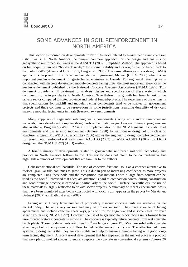
Facing units: A very large number of proprietary masonry concrete units are available on the
market today. The units vary in size and may be hollow or solid. They have a range of facing
appearances and include concrete shear keys, pins or clips for alignment and is some cases for layer
shear transfer (e.g. NCMA 1997). However, the use of larger modular block facing units formed from
unreinforced wet-cast concrete is growing. The concrete is typically return concrete from wet concrete
batch plants. These modular units are often 1 m3 are larger (Figure 19). Most are solid with concrete
shear keys but some systems are hollow to reduce the mass of concrete. The attraction of these
systems to designers is that they are very stable and help to ensure a durable facing with good long-
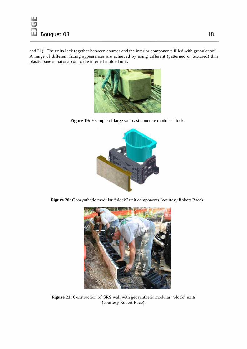
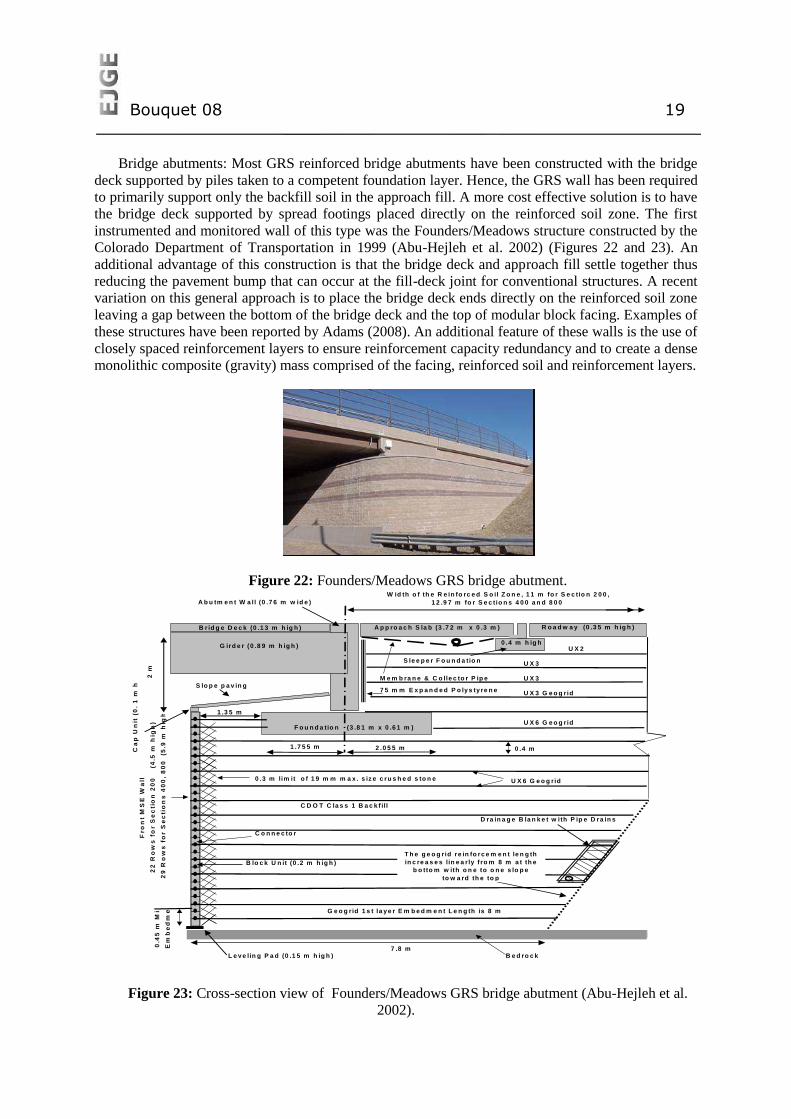
term facing alignment. A recent novel development that has appeared in the market place is a product
that uses plastic molded shapes to entirely replace the concrete in conventional systems (Figures 20
Bouquet 08 18
and 21). The units lock together between courses and the interior components filled with granular soil.
A range of different facing appearances are achieved by using different (patterned or textured) thin
plastic panels that snap on to the internal molded unit.
Figure 19: Example of large wet-cast concrete modular block.
Figure 20: Geosynthetic modular “block” unit components (courtesy Robert Race).
Figure 21: Construction of GRS wall with geosynthetic modular “block” units
(courtesy Robert Race).
Bouquet 08 19
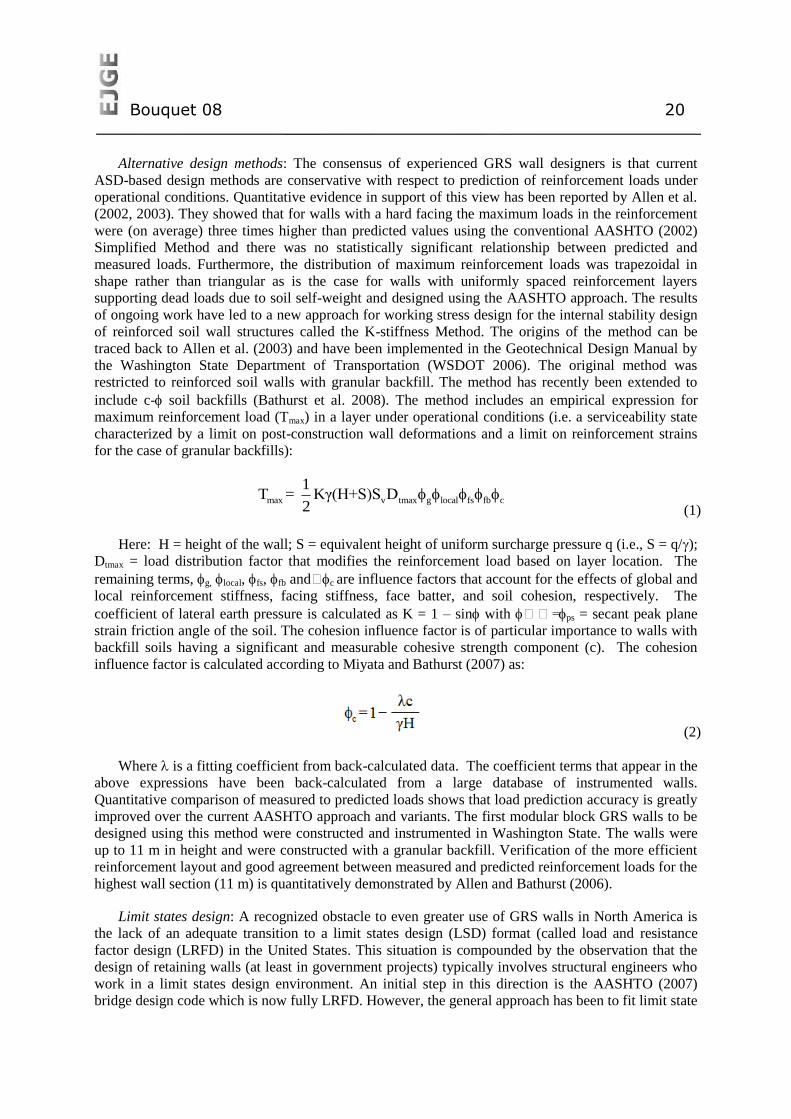
Bridge abutments: Most GRS reinforced bridge abutments have been constructed with the bridge
deck supported by piles taken to a competent foundation layer. Hence, the GRS wall has been required
to primarily support only the backfill soil in the approach fill. A more cost effective solution is to have
the bridge deck supported by spread footings placed directly on the reinforced soil zone. The first
instrumented and monitored wall of this type was the Founders/Meadows structure constructed by the
Colorado Department of Transportation in 1999 (Abu-Hejleh et al. 2002) (Figures 22 and 23). An
additional advantage of this construction is that the bridge deck and approach fill settle together thus
reducing the pavement bump that can occur at the fill-deck joint for conventional structures. A recent
variation on this general approach is to place the bridge deck ends directly on the reinforced soil zone
leaving a gap between the bottom of the bridge deck and the top of modular block facing. Examples of
these structures have been reported by Adams (2008). An additional feature of these walls is the use of
closely spaced reinforcement layers to ensure reinforcement capacity redundancy and to create a dense
monolithic composite (gravity) mass comprised of the facing, reinforced soil and reinforcement layers.
Figure 22: Founders/Meadows GRS bridge abutment.
Figure 23: Cross-section view of Founders/Meadows GRS bridge abutment (Abu-Hejleh et al.
2002).
U X 2
U X 3
U X 3
U X 3 G e o g rid
U X 6 G e o g rid
C o n n e c to r
B lo c k U n it (0 .2 m h ig h )
L e v e lin g P a d (0 .1 5 m h ig h ) B e d ro c k
7 .8 m
0 .4 m
G e o g rid 1 s t la y e r E m b e d m e n t L e n g th is 8 m
F o u n d a tio n (3 .8 1 m x 0 .6 1 m )
R o a d w a y (0 .3 5 m h ig h )A p p ro a c h S la b (3 .7 2 m x 0 .3 m )
G ird e r (0 .8 9 m h ig h )
B r id g e D e c k (0 .1 3 m h ig h )
0 .4 m h ig h
C D O T C la s s 1 B a c k f ill
Fro
nt
MS
E W
all
22
Ro
ws
fo
r S
ec
tio
n 2
00
(4
.5 m
hig
h)
29
Ro
ws
fo
r S
ec
tio
ns
40
0,
80
0
(5.9
m h
igh
)0
.45
m M
in.
Em
be
dm
en
t
M e m b ra n e & C o lle c to r P ip e
T h e g e o g rid re in fo rc e m e n t le n g th
in c re a s e s lin e a rly f ro m 8 m a t th e
b o tto m w ith o n e to o n e s lo p e
to w a rd th e to p
Ca
p U
nit
(0
. 1
m h
igh
)
1 .7 5 5 m 2 .0 5 5 m
A b u tm e n t W a ll (0 .7 6 m w id e )
W id th o f th e R e in fo rc e d S o il Z o n e , 1 1 m fo r S e c tio n 2 0 0 ,
1 2 .9 7 m fo r S e c tio n s 4 0 0 a n d 8 0 0
2 m
S lo p e p a v in g7 5 m m E x p a n d e d P o ly s ty re n e
S le e p e r F o u n d a tio n
0 .3 m lim it o f 1 9 m m m a x . s iz e c ru s h e d s to n e
1 .3 5 m
D ra in a g e B la n k e t w ith P ip e D ra in s
U X 6 G e o g rid
Bouquet 08 20
Alternative design methods: The consensus of experienced GRS wall designers is that current
ASD-based design methods are conservative with respect to prediction of reinforcement loads under
operational conditions. Quantitative evidence in support of this view has been reported by Allen et al.
(2002, 2003). They showed that for walls with a hard facing the maximum loads in the reinforcement
were (on average) three times higher than predicted values using the conventional AASHTO (2002)
Simplified Method and there was no statistically significant relationship between predicted and
measured loads. Furthermore, the distribution of maximum reinforcement loads was trapezoidal in
shape rather than triangular as is the case for walls with uniformly spaced reinforcement layers
supporting dead loads due to soil self-weight and designed using the AASHTO approach. The results
of ongoing work have led to a new approach for working stress design for the internal stability design
of reinforced soil wall structures called the K-stiffness Method. The origins of the method can be
traced back to Allen et al. (2003) and have been implemented in the Geotechnical Design Manual by
the Washington State Department of Transportation (WSDOT 2006). The original method was
restricted to reinforced soil walls with granular backfill. The method has recently been extended to
include c- soil backfills (Bathurst et al. 2008). The method includes an empirical expression for
maximum reinforcement load (Tmax) in a layer under operational conditions (i.e. a serviceability state
characterized by a limit on post-construction wall deformations and a limit on reinforcement strains
for the case of granular backfills):
max v tmax g local fs fb c
1T = Kγ(H+S)S D
2
(1)
Here: H = height of the wall; S = equivalent height of uniform surcharge pressure q (i.e., S = q/);
Dtmax = load distribution factor that modifies the reinforcement load based on layer location. The
remaining terms, g, local, fs, fb andc are influence factors that account for the effects of global and
local reinforcement stiffness, facing stiffness, face batter, and soil cohesion, respectively. The
coefficient of lateral earth pressure is calculated as K = 1 – sin with = ps = secant peak plane
strain friction angle of the soil. The cohesion influence factor is of particular importance to walls with
backfill soils having a significant and measurable cohesive strength component (c). The cohesion
influence factor is calculated according to Miyata and Bathurst (2007) as:
(2)
Whereis a fitting coefficient from back-calculated data. The coefficient terms that appear in the
above expressions have been back-calculated from a large database of instrumented walls.
Quantitative comparison of measured to predicted loads shows that load prediction accuracy is greatly
improved over the current AASHTO approach and variants. The first modular block GRS walls to be
designed using this method were constructed and instrumented in Washington State. The walls were
up to 11 m in height and were constructed with a granular backfill. Verification of the more efficient
reinforcement layout and good agreement between measured and predicted reinforcement loads for the
highest wall section (11 m) is quantitatively demonstrated by Allen and Bathurst (2006).
Limit states design: A recognized obstacle to even greater use of GRS walls in North America is
the lack of an adequate transition to a limit states design (LSD) format (called load and resistance
factor design (LRFD) in the United States. This situation is compounded by the observation that the
design of retaining walls (at least in government projects) typically involves structural engineers who
work in a limit states design environment. An initial step in this direction is the AASHTO (2007)
bridge design code which is now fully LRFD. However, the general approach has been to fit limit state
Bouquet 08 21
equations to ASD equations so that load and resistance factors matching a given reliability index value
give the same factor of safety as in conventional practice. This is not an entirely satisfactory approach
since it does not guarantee a uniform level of reliability for all possible limit states. Formal procedures
to carry out rigorous calibration have only just begun for GRS walls. An example of the general
approach described in a way that is familiar to geotechnical engineers can be found in a recent TRR
circular (Allen et al. 2005). An advantage of the K-stiffness Method described earlier is that it can be
easily recast into a limit states design format (at least for the calculation of internal reinforcement
loads) since the underlying deterministic model has been calibrated using a statistical treatment of
measured and predicted reinforcement loads. An initial step in this direction can be seen in the
WSDOT (2006) design guidance document mentioned earlier.
SOME ADVANCES IN GEOENVIRONMENTAL
APPLICATIONS USING GEOSYNTHETICS
Geosynthetics play an important role in environmental applications because of their versatility,
cost-effectiveness, ease of installation, and consistency in their mechanical and hydraulic properties.
Geosynthetics also can offer a technical advantage in relation to traditional liner systems or other
containment systems. The use of geomembranes as the primary water proofing element at the
Contrada Sabetta Dam, Italy (Cazzuffi 1987) and to keep an upstream clay seepage control liner from
dessicating in the Mission Dam (today Terzaghi Dam), Canada (Terzaghi & Lacroix 1964) in the late
1950’s represent applications that have been the precursors of today’s usage of geosynthetics in
containment systems. Both applications predated the use of conventional geosynthetics by some 20
years. Geosynthetic systems are nowadays an accepted and well-established component of the landfill
industry (since at least early 1980’s). Containment systems for landfills typically include both
geosynthetics and earthen material components, (e.g. compacted clays for liners, granular media for
drainage layers, and various soils for protective and vegetative layers).
The state of the art on the use of geosynthetics in waste containment facilities previous to this
period has been documented by various important sources, which have set the path for the growth of
geosynthetics in this field (e.g. Giroud & Cazzuffi 1989; Koerner 1990; Cancelli & Cazzuffi 1994;
Gourc 1994; Rowe et al. 1995; Manassero et al. 1998; Rowe 1998; Bouazza et al. 2002, Junqueira et
al. 2006).
This section focuses on some recent advances on the use of geosynthetics in environmental
applications, including the design of geosynthetics in liquid collection systems and of reinforced
cover systems.
The multiple uses of geosynthetics in the design of modern municipal solid waste landfills is a
good illustration of an application in which the different geosynthetics can be and have been used to
perform all the functions discussed previously. Virtually all the different types of geosynthetics
discussed previously have been used in the design of both base and cover liner systems of landfill
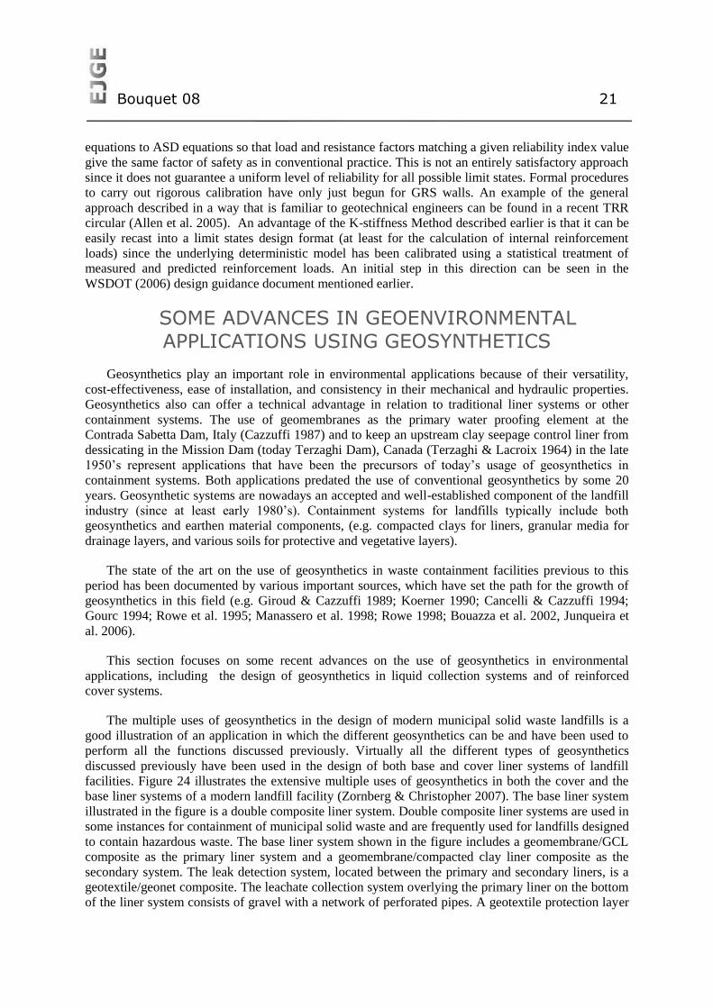
facilities. Figure 24 illustrates the extensive multiple uses of geosynthetics in both the cover and the
base liner systems of a modern landfill facility (Zornberg & Christopher 2007). The base liner system
illustrated in the figure is a double composite liner system. Double composite liner systems are used in
some instances for containment of municipal solid waste and are frequently used for landfills designed
to contain hazardous waste. The base liner system shown in the figure includes a geomembrane/GCL
composite as the primary liner system and a geomembrane/compacted clay liner composite as the
secondary system. The leak detection system, located between the primary and secondary liners, is a
geotextile/geonet composite. The leachate collection system overlying the primary liner on the bottom
of the liner system consists of gravel with a network of perforated pipes. A geotextile protection layer
Bouquet 08 22
beneath the gravel provides a cushion to protect the primary geomembrane from puncture by stones in
the overlying gravel. The leachate collection system overlying the primary liner on the side slopes of
the liner system is a geocomposite sheet drain (geotextile/geonet composite) merging into a gravel
layer. A geotextile filter covers the entire footprint of the landfill and minimizes clogging of the
leachate collection and removal system. The groundwater level may be controlled at the bottom of the
landfill by gradient control drains built using geotextile filters. Moreover, the foundation soil below
the bottom of the landfill may be stabilized as shown in the figure using randomly distributed fiber
reinforcements, while the steep side soil slopes beneath the liner could also be reinforced using
geogrids. Different types of geosynthetics (e.g. geogrids, geotextiles, fibers) could have been selected
for stabilization of the foundation soils.
The cover system of the landfill illustrated in Figure 24 contains a composite geomembrane/GCL
barrier layer. The drainage layer overlying the geomembrane is a geocomposite sheet drain (composite
geotextile/geonet). In addition, the soil cover system may include geogrid, geotextile, or geocell
reinforcements below the infiltration barrier system. This layer of reinforcements may be used to
minimize the strains that could be induced in the barrier layers by differential settlements of the refuse
or by a future vertical expansion of the landfill. In addition, the cover system could include geogrid or
geotextile reinforcement above the infiltration barrier to provide stability to the vegetative cover soil.
Fiber reinforcement may also be used for stabilization of the steep portion of the vegetative cover soil.
A geocomposite erosion control system above the vegetative cover soil is indicated in the figure and
provides protection against sheet and gully erosion. Fig. 24 also illustrates the use of geosynthetics
within the waste mass, which are used to facilitate waste placement during landfilling. Specifically,
the figure illustrates the use of geotextiles as daily cover layers and of geocomposites within the waste
mass for collection of gas and leachate. Geosynthetics can also be used as part of the groundwater and
leachate collection well system. The use of geotextiles as filters in groundwater and leachate
extraction wells is illustrated in the figure. Finally, the figure shows the use of an HDPE vertical
barrier system and a geocomposite interceptor drain along the perimeter of the facility. Although not
all of the components shown in Figure 24 would normally be needed at any one landfill facility, the
figure illustrates the many geosynthetic applications that can be considered in landfill design.
Bouquet 08 23
Figure 24: Multiple uses of geosynthetics in landfill design (from Zornberg & Christopher 2007).
Geosynthetics in Liquid Collection Systems
Calculating the thickness of liquid in a liquid collection layer is an important design step because
one of the design criteria for a liquid collection layer is that the maximum thickness of the liquid
collection layer must be less than an allowable thickness. The term “thickness” is used instead of the
more familiar term “depth”, because thickness (measured perpendicular to the liquid collection layer
slope), and not depth (measured vertically), is actually used in design.
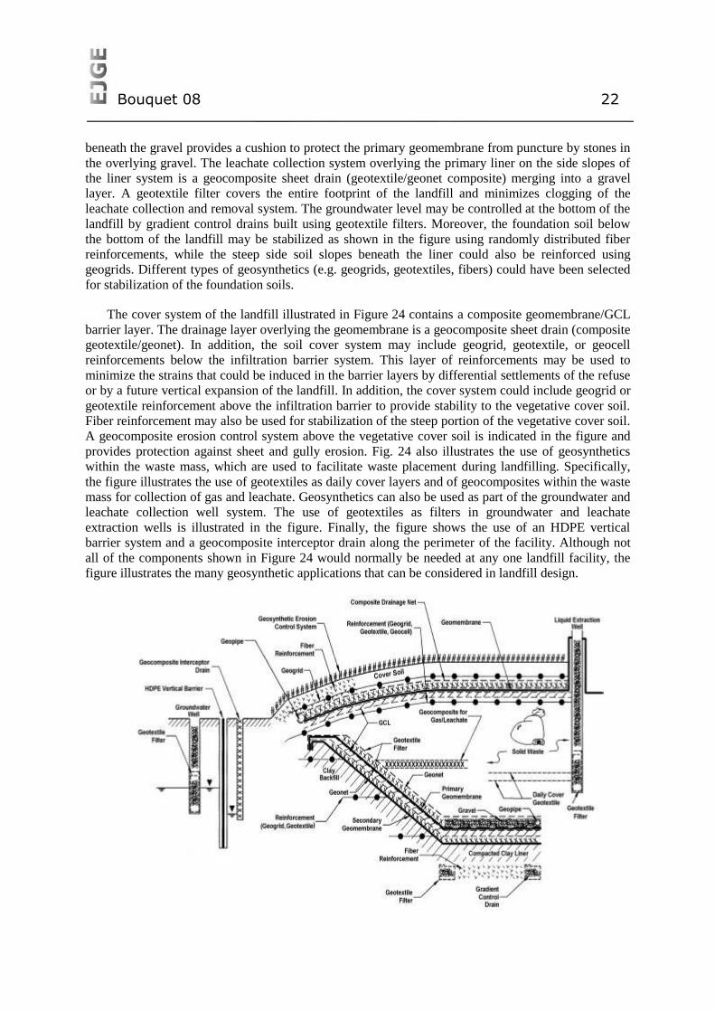
The thickness of liquid in a liquid collection layer depends on the rate of liquid supply. A typical
case of liquid supply is that of liquid impinging onto the liquid collection layer. Two examples of
liquid collection layers with such a type of liquid supply can be found in landfills (Fig. 25): (i) the
drainage layer of the cover system (Fig. 25a), where the liquid that impinges onto the liquid collection
layer is the precipitation water that has percolated through the soil layer overlying the drainage layer;
and (ii) the leachate collection layer (Fig. 25b), where the liquid that impinges onto the leachate
collection layer is the leachate that has percolated through the waste and through the protective soil
layer overlying the leachate collection layer (Giroud et al., 2000a). The terminology “liquid
impingement rate” is often used in the case of landfills to designate the rate of liquid supply.
Equations are available (Giroud et al. 2000a) to calculate the maximum thickness of liquid in a
liquid collection layer that meets the following conditions:
the liquid supply rate is uniform (i.e. it is the same over the entire area of the liquid
collection layer) and is constant (i.e. it is the same during a period of time that is
long enough that steady-state flow conditions can be reached);
the liquid collection layer is underlain by a geomembrane liner without defects and,
therefore, liquid losses are negligible;
the slope of the liquid collection layer is uniform (a situation referred to herein as
“single slope”) ; and
there is a drain at the toe of the slope that promptly removes the liquid.
Bouquet 08 24
Figure 25: Examples of liquid collection layers subjected to a uniform supply of liquid in a
landfill: (a) drainage layer in a cover system; (b) leachate collection layer (Giroud et al. 2000a).
The last two conditions are not met in cases where the liquid collection layer comprises two
sections on different slopes, with no drain removing the liquid at the connection between the two
sections; in those cases, the only drain is at the toe of the downstream section.
Regulatory equivalency between natural and geocomposite lateral drainage systems is currently
based on equivalent transmissivity. However, Giroud et al. (2000c) have demonstrated that this
practice is incorrect and non-conservative. An equivalency based solely on transmissivity will lead to
selection of a geosynthetic drainage layer that may not provide adequate flow capacity and may result
in the development of water pressure.
Equivalency between two lateral drainage systems must take into consideration the service flow
gradients and maximum liquid thickness. Giroud et al. (2000c) have shown that, to be equivalent to a
natural drainage layer, the minimum transmissivity of the geocomposite must be greater than the
tranmissivity of the natural drainage layer. The minimum transmissivity of the geonet is obtained by
multiplying the transmissivity of the natural drainage layer by an equivalency factor, E. For natural
drainage layers having maximum flow depths of 0.30 m, E can be approximated as follows:
tan
cos
88.01
88.0
1
L
t = E
prescribed
(3)
where tprescribed is the maximum liquid thickness prescribed by regulations. The equivalency defined by
Equation 3 is based on equal unconfined flow volumes in natural and geocomposite drainage systems.
However, the very low heads associated with unconfined flow in a geocomposite lateral drain will
Bouquet 08 25
result in a significantly reduced head acting on the underlying liner system, and therefore in a reduced
potential leakage.
Reinforced Cover Systems
General considerations
The design of veneer slopes (e.g. steep cover systems for waste containment facilities) poses
significant challenges to designers. The use of uniaxial reinforcements placed along the slope (under
the veneer and above a typically strong mass of soil or solid waste) and anchored on the top of the
slope has been a common design approach (Palmeira and Viana 2003). However, this alternative may
not be feasible for steep, long veneer slopes. As the veneer slope rests on top of a comparatively
stronger mass solid waste, alternative approaches can be considered. This includes use of uniaxial
reinforcements placed horizontally (rather than along the slope) and anchored into the underlying
mass. A second alternative includes the use of fiber-reinforced soil. A review of analyses for veneers
reinforced using horizontally placed inclusions is presented in this section.
This section presents an analytical framework for quantification of the reinforcement requirements
for reinforced veneers where reinforcements are placed horizontally and embedded into a
comparatively strong underlying mass. Emphasis in this evaluation is placed on the assessment of an
infinite slope configuration. This allows direct comparison of the different reinforcement alternatives.
Design criteria for reinforced soil structure have been the focus of significant debate (Zornberg &
Leshchinsky 2001). Although different definitions for the factor of safety have been reported for the
design of reinforced soil slopes, the definition used in this study is relative to the shear strength of the
soil:
Available soil shear strengthFS =
Soil shear stress required for equilibrium (4)
This definition is consistent with conventional limit equilibrium analysis, for which extensive
experience has evolved for the analysis of unreinforced slopes. Current design practices for reinforced
soil slopes often consider approaches that decouple the soil reinforcement interaction and do not
strictly consider the factor of safety defined by Equation 4. Such analyses neglect the influence of
reinforcement forces on the soil stresses along the potential failure surface and may result in factors of
safety significantly different than those calculated using more rigorous approaches. Considering the
normal and shear forces acting in a control volume along the veneer slope (or infinite slope), and
assuming a Mohr-Coulomb shear strength envelope, Equation 4 can be expressed as:
LS
LNc = FS
/
tan)/(
(5)
where N = normal force acting on the control volume; S = shear force acting on the control
volume; L = length of the control volume; c = soil cohesion; and = soil friction angle.
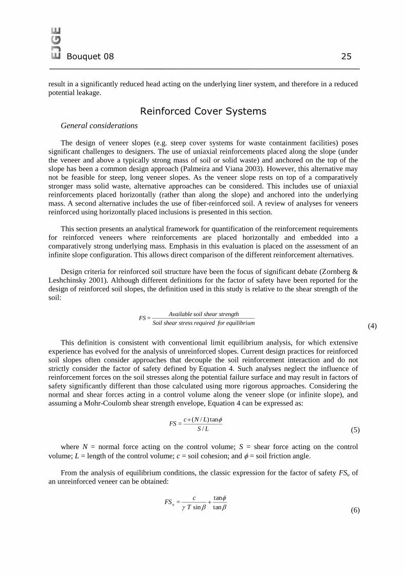
From the analysis of equilibrium conditions, the classic expression for the factor of safety FSu of
an unreinforced veneer can be obtained:
tan
tan
sin
T
c = FSu
(6)
Bouquet 08 26
Figure 26: Unreinforced veneer.
Covers Reinforced with Uniaxial Geosynthetics Parallel to the Slope
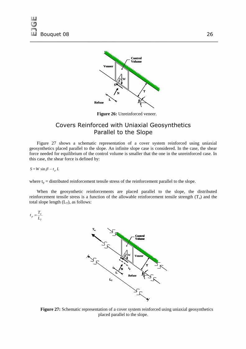
Figure 27 shows a schematic representation of a cover system reinforced using uniaxial
geosynthetics placed parallel to the slope. An infinite slope case is considered. In the case, the shear
force needed for equilibrium of the control volume is smaller that the one in the unreinforced case. In
this case, the shear force is defined by:
LtW = S psin (7)
where tp = distributed reinforcement tensile stress of the reinforcement parallel to the slope.
When the geosynthetic reinforcements are placed parallel to the slope, the distributed
reinforcement tensile stress is a function of the allowable reinforcement tensile strength (Ta) and the
total slope length (LT), as follows:
T
ap
L
Tt
(8)
Figure 27: Schematic representation of a cover system reinforced using uniaxial geosynthetics
placed parallel to the slope.
Refuse
Veneer
ControlVolume
T
W
L
N
S
Refuse
Veneer
ControlVolume
T
W
L
N
S
L
N
ControlVolume
T
WS
Refuse
Veneer
L
N
ControlVolume
T
W
tp
S
Ta
LT
L
N
ControlVolume
T
WS
Refuse
Veneer
L
N
ControlVolume
T
W
tp
S
Ta
LTLT
Bouquet 08 27
From limit equilibrium analysis, the factor of safety for the parallel-reinforcement case, FSr,p , can
be estimated as:
sin1
tan
tan
sin,
T
t
T
c
= FSp
pr
(9) (9)
Equation 9 provides a convenient expression for stability evaluation of reinforced veneer slopes. It
should be noted that if the distributed reinforcement tensile stress t equals zero (i.e. in the case of
unreinforced veneers), Equation 9 leads to FSr,p = FSu .
Covers Reinforced with Horizontal Uniaxial Geosynthetics
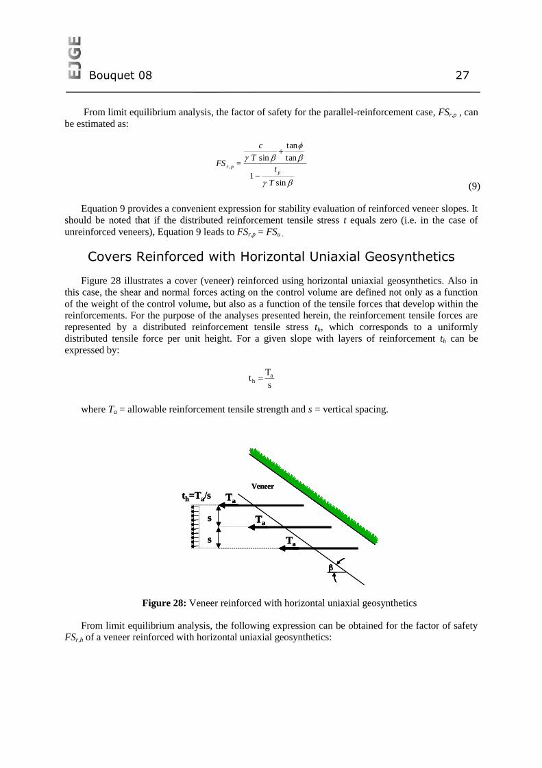
Figure 28 illustrates a cover (veneer) reinforced using horizontal uniaxial geosynthetics. Also in
this case, the shear and normal forces acting on the control volume are defined not only as a function
of the weight of the control volume, but also as a function of the tensile forces that develop within the
reinforcements. For the purpose of the analyses presented herein, the reinforcement tensile forces are
represented by a distributed reinforcement tensile stress th, which corresponds to a uniformly
distributed tensile force per unit height. For a given slope with layers of reinforcement th can be
expressed by:
s
Tt a
h (10)
where Ta = allowable reinforcement tensile strength and s = vertical spacing.
Figure 28: Veneer reinforced with horizontal uniaxial geosynthetics
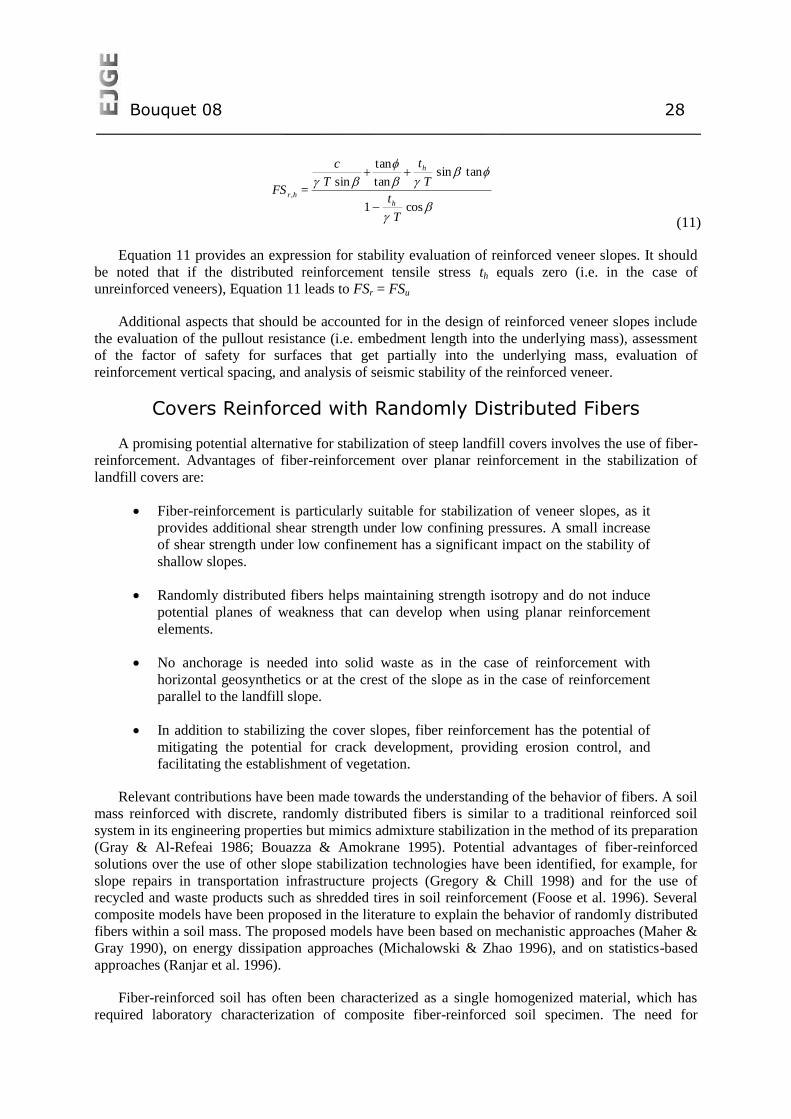
From limit equilibrium analysis, the following expression can be obtained for the factor of safety
FSr,h of a veneer reinforced with horizontal uniaxial geosynthetics:
Veneer
Ta
Ta
Ta
s
s
th=Ta/s
Veneer
TaTa
TaTa
TaTa
s
s
th=Ta/s
Bouquet 08 28
cos1
tansintan
tan
sin,
T
t
T
t
T
c
= FSh
h
hr
(11) (11)
Equation 11 provides an expression for stability evaluation of reinforced veneer slopes. It should
be noted that if the distributed reinforcement tensile stress th equals zero (i.e. in the case of
unreinforced veneers), Equation 11 leads to FSr = FSu
Additional aspects that should be accounted for in the design of reinforced veneer slopes include
the evaluation of the pullout resistance (i.e. embedment length into the underlying mass), assessment
of the factor of safety for surfaces that get partially into the underlying mass, evaluation of
reinforcement vertical spacing, and analysis of seismic stability of the reinforced veneer.
Covers Reinforced with Randomly Distributed Fibers
A promising potential alternative for stabilization of steep landfill covers involves the use of fiber-
reinforcement. Advantages of fiber-reinforcement over planar reinforcement in the stabilization of
landfill covers are:
Fiber-reinforcement is particularly suitable for stabilization of veneer slopes, as it
provides additional shear strength under low confining pressures. A small increase
of shear strength under low confinement has a significant impact on the stability of
shallow slopes.
Randomly distributed fibers helps maintaining strength isotropy and do not induce
potential planes of weakness that can develop when using planar reinforcement
elements.
No anchorage is needed into solid waste as in the case of reinforcement with
horizontal geosynthetics or at the crest of the slope as in the case of reinforcement
parallel to the landfill slope.
In addition to stabilizing the cover slopes, fiber reinforcement has the potential of
mitigating the potential for crack development, providing erosion control, and
facilitating the establishment of vegetation.
Relevant contributions have been made towards the understanding of the behavior of fibers. A soil
mass reinforced with discrete, randomly distributed fibers is similar to a traditional reinforced soil
system in its engineering properties but mimics admixture stabilization in the method of its preparation
(Gray & Al-Refeai 1986; Bouazza & Amokrane 1995). Potential advantages of fiber-reinforced
solutions over the use of other slope stabilization technologies have been identified, for example, for
slope repairs in transportation infrastructure projects (Gregory & Chill 1998) and for the use of
recycled and waste products such as shredded tires in soil reinforcement (Foose et al. 1996). Several
composite models have been proposed in the literature to explain the behavior of randomly distributed
fibers within a soil mass. The proposed models have been based on mechanistic approaches (Maher &
Gray 1990), on energy dissipation approaches (Michalowski & Zhao 1996), and on statistics-based
approaches (Ranjar et al. 1996).
Fiber-reinforced soil has often been characterized as a single homogenized material, which has
required laboratory characterization of composite fiber-reinforced soil specimen. The need for
Bouquet 08 29
laboratory characterization has been a major drawback in the implementation of fiber-reinforcement in
soil stabilization projects. To overcome this difficulty, a discrete approach that characterizes the fiber-
reinforced soil as a two-component (fibers and soil) material was recently developed (Zornberg 2002).
The main features of this approach are:
The reinforced mass is characterized by the mechanical properties of individual
fibers and of the soil matrix rather than by the mechanical properties of the fiber-
reinforced composite material
A critical confining pressure at which the governing mode of failure changes from
fiber pullout to fiber breakage can be defined using the individual fiber and soil matrix
properties.
The fiber-induced distributed tension is a function of fiber content, fiber aspect
ratio, and interface shear strength of individual fibers if the governing mode of failure
is by fiber pullout.
The fiber-induced distributed tension is a function of fiber content and ultimate
tensile strength of individual fibers if the governing mode of failure is by fiber
breakage.
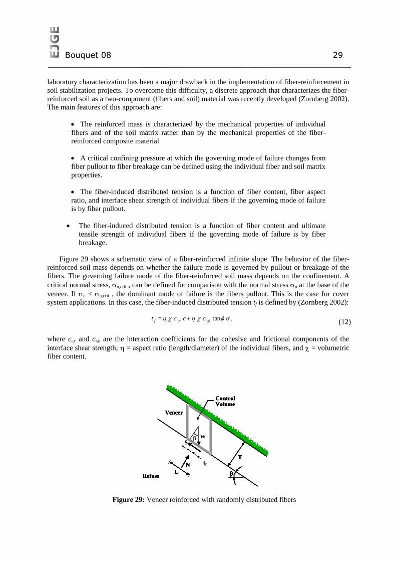
Figure 29 shows a schematic view of a fiber-reinforced infinite slope. The behavior of the fiber-
reinforced soil mass depends on whether the failure mode is governed by pullout or breakage of the
fibers. The governing failure mode of the fiber-reinforced soil mass depends on the confinement. A
critical normal stress, n,crit , can be defined for comparison with the normal stress n at the base of the
veneer. If n < n,crit , the dominant mode of failure is the fibers pullout. This is the case for cover
system applications. In this case, the fiber-induced distributed tension tf is defined by (Zornberg 2002):
nicif ccc = t tan,, (12)
where ci,c and ci, are the interaction coefficients for the cohesive and frictional components of the
interface shear strength; = aspect ratio (length/diameter) of the individual fibers, and = volumetric
fiber content.
Figure 29: Veneer reinforced with randomly distributed fibers
Refuse
Veneer
L
N
ControlVolume
T
WS
Refuse
Veneer
L
N
ControlVolume
T
W
tf
S
Refuse
Veneer
L
N
ControlVolume
T
WS
Refuse
Veneer
L
N
ControlVolume
T
W
tf
S
Bouquet 08 30
Similarly, if n > n,crit , the dominant mode of failure is fiber breakage. Even though this is not
generally the governing mode of failure for cover slopes the solution for this case is presented for
completeness. The fiber-induced distributed tension tf is defined by:
ultft = t , (13)
where f,ult = ultimate tensile strength of the individual fiber.
In a fiber-reinforced veneer, the shear force needed for equilibrium of the control volume equals:
LtW = S f sin
(14)
where α is an empirical coefficient that accounts for preferential orientation of fibers. For the case of
randomly distributed fibers considered herein α equals one.
From limit equilibrium analysis, the factor of safety for a fiber-reinforced veneer, FSr,f:, is given by
sin1
tan
tan
sin,
T
t
T
c
= FSf
fr
(15)
Solutions were presented for the case of unreinforced, slope-parallel, horizontally-reinforced and
fiber-reinforced veneers. As expected, additional reinforcement always leads to a higher factor of
safety while increasing slope inclination would typically lead to decreasing stability. Yet, it is worth
noting that increasing soil friction angle leads to increasing stability, when compared to the
unreinforced case, only for the case of fiber reinforced slopes. Also, it should also be noted that
increasing total height of the slope (or increasing total length) does not affect detrimentally the
efficiency of horizontally placed reinforcements and of fiber reinforcement.
CONCLUSIONS
Geosynthetics have great potential to be used as cost-effective solutions for several engineering
problems. This paper presented recent advances in geosynthetic products, on the utilization of these
materials in reinforced soil structures and in environmental applications. Manufacturing of
geosynthetics products allows incorporating recent advances in material sciences. Therefore, the
expectation is that innovations in products, types and properties will continue to take place, adding to
the already vast range of applications of these materials.
Geosynthetic reinforced soil retaining walls present better performance than traditional retaining
walls under dynamic loadings and this has been demonstrated by a number of case histories of
prototype structures that have withstood severe earthquakes. Thus, this type of structure can be cost-
effective not only under static loading but also in regions where significant seismic activities are
expected. New construction methodologies have also broaden the applications of geosynthetic
reinforced soil retaining wall, which include new facing units and that reduces the construction time,
costs and allow better aesthetic conditions for the final structure.
Investigations on the behaviour of large model reinforced walls built under controlled conditions,
monitoring of real structures and theoretical studies have yielded the development of a practical
method for the estimate of reinforcement loads, including the case of using cohesive backfill. This
Bouquet 08 31
method is a significant advance on existing design approaches and will allow the construction of
cheaper structures.
The use of geosynthetics has also led to major advances in environmental applications. While
geosynthetics has been used in a number of applications in environmental project, this paper has
described advances on the use of geosynthetics in landfills. Specifically, simple yet accurate
formulations are now available for the design of liquid collection systems, which involve proper
quantification of the thickness of liquid within drainage composites. Also, significant advances have
taken place regarding the use of reinforcements for stabilization of steep cover systems. Approach
include the use of geosynthetic reinforcements parallel to the cover slope, horizontal reinforcements
embedded into solid waste, and fiber reinforcement of the cover soils. Overall, the use of
geosynthetics has led to major advances towards the construction environmental systems that are cost-
effective but that provide enhanced environmental protection.
REFERENCES
1. AASHTO (2002) “Standard Specifications for Highway Bridges” American Association
of State Highway and Transportation Officials (AASHTO), 17th ed., Washington, D.C.
2. AASHTO (2007) “LRFD Bridge Design Specifications” American Association of State
Highway and Transportation Officials, Fourth Edition, Washington, D.C., USA.
3. Abu-Hejleh, N., Zornberg, J.G., Wang, T. and Watcharamonthein, J. (2002) “Monitored
Displacements of Unique Geosynthetic-Reinforced Soil Bridge Abutments”.
Geosynthetics International, 9(1): 71-95.
4. Adams, M. (2008) “The GRS bridges of Defiance County”. Geosynthetics, 26(1): 14-21.
5. Allen, T.M. and Bathurst, R.J. (2006) “Design and performance of an 11-m high block-
faced geogrid wall”. 8th International Conference on Geosynthetics, Yokohama, Japan,
September 2006, 953-956
6. Allen, T.M. and Holtz, R.D. (1991) “Design of retaining walls reinforced with
geosynthetics“. In Geotechnical Engineering Congress 1991, McLean, F., Campbell,
D.A., and Harris, D.W., Editors, ASCE Geotechnical Special Publication No. 27, Vol. 2,
In proceedings of a congress held in Boulder, Colorado, USA, June 1991, 970-987.
7. Allen, T.M., Bathurst, R.J., Holtz, R.D., Walters, D.L. and Lee, W.F. (2003) “A New
Working Stress Method for Prediction of Reinforcement Loads in Geosynthetic Walls”.
Canadian Geotechnical Journal, 40(5): 976-994.
8. Allen, T.M., Nowak, A.S. and Bathurst, R.J. (2005) “Calibration to Determine Load and
Resistance Factors for Geotechnical and Structural Design”, Transportation Research
Board Circular E-C079, Washington, DC, 93 p.
9. Alexiew, D. (2008) “Ultimate bearing capacity tests on an experimental geogrid-
reinforced vertical bridge abutment without stiffening facing”, New Horizons in Earth
Reinforcement, Taylor & Francis Group, London, 507-511.
Bouquet 08 32
10. Aydogmus, T., Alexiew, D. and Klapperich, H. (2007) “Laboratory testing of interaction
performance of PVA geogrids embedded in stabilized cohesive soils”, 14th European
Conference on Soil Mechanics and Geotechnical Engineering, Madrid 2007, 1417-1420.
11. Bathurst, R.J. (2007) “Geosynthetics Classification”. IGS Leaflets on Geosynthetics
Applications, IGS Education Committee, available at at www.geosyntheticssociety.org.
12. Bathurst, R.J., Miyata, Y., Nernheim, A. and Allen, T.M. (2008) “Refinement of K-
Stiffness Method for Geosynthetic Reinforced Soil Walls”, Geosynthetics International,
15(5) (in press).
13. Berg, R.R., Allen, T.M. and Bell, J.R. (1998) “Design procedures for reinforced soil walls
- A historical perspective”. 6th International Conference on Geosynthetics, IFAI, Atlanta,
Georgia, USA, 2: 491-496.
14. Blume, K., Alexiew, D. and Glötzl, F. (2006) “The new federal highway (Autobahn) A26
in Germany with high geosynthetic reinforced embankments on soft soils”, Geosynthetics,
Milpress, Rotterdam, 913-916.
15. Bouazza, M., Zornberg, J.G., and Adam, D. (2002). “Geosynthetics in Waste Containment
Facilities: Recent Advances.” Keynote paper, Proc. Seventh Intl. Conf. on Geosynthetics,
Nice, France, 22-27 September, A.A. Balkema, 2: 445-510.
16. Bouazza, A. and Amokrane, K. (1995) “Granular soil reinforced with randomly
distributed fibres”. 11th African Regional Conf. on Soil Mech. & Foundation Eng., Cairo:
207-216.
17. Bressi, G., Zinessi, M., Montanelli, F. and Rimoldi, P. (1995) « The slope stability of
GCL layers in geosynthetic lining system”. 5th Intl. Symp. on Landfills, Cagliari 1: 595-
610.
18. Brokemper, D. , Sobolewski, J. and Alexiew, D. (2006) “Design and construction of
geotextile encased columns supporting geogrid reinforced landscape embankments”;
Bastions Vijfwal Houten in the Netherlands, Geosynthetics, Milpress, Rotterdam, pgs
889-892.
19. Bygness, R. (2007) “Using geosynthetics for avalanche protection in northern Iceland”,
Geosynthetics, Oct-Nov 2007 25(5): 16-20.
20. Byrne, R.J., Kendall, J. & Brown, S. (1992) “Cause and mechanism of failure, Kettleman
hills landfill B-19, Unit 1A”. Stability and Performance of Slopes and Embankments,
ASCE. Geot. Sp. Publication 31: 1188-1520.
21. Canadian Geotechnical Society Canadian (2006) “Foundation Engineering Manual
(CFEM)”, 4th edition, BiTech Publishers, Richmond, BC, Canada.
22. Cancelli, A. and Cazzuffi, D. (1994) “Env. aspects of geosynthetic applications in andfills
and dams”. Proc. 5th Intl. Conf. on Geosynthetics, Singapore 4: 55-96.
23. Cargill, K.W. and Olen, K.L. (1998) “Landfill closure using reinforced soil slopes”. Proc.
6th Intl. Conf. on Geosynthetics, Atlanta : 481-486.
Bouquet 08 33
24. Cazzuffi, D. (1987) “The use of geomembranes in Italian dams”. Intl. J. of Water Power
and Dam Construction 26(2): 44-52.
25. Collins, P., Ng, A.S. and Ramanujam, R. (1998) “Superfund success, superfast”. Civil
Eng., Decembre: 42-45.
26. Daniel, D. E., Koerner, R., Bonaparte, R., Landreth, R., Carson, D. and Scranton, H.
(1998) “Slope stability of geosynthetic clay liner test plots”. J. of Geot. and GeoEnv. Eng.
124(7): 628-637.
27. Eid, H.T and Stark, T.D. (1997) “Shear behaviour of an unreinforced geosynthetic clay
liner”. Geosynthetics Intl. 4(6): 645-659.
28. Eid, H.T., Stark, T.D. and Doerfler, C.K. (1999) “Effect of shear displacement rate on
internal shear strength of a reinforced geosynthetic clay liners”. Geosynthetics Intl. 6(3):
219-239.
29. Elias, J.M. (2000) “Properties of the new laser welded geogrid made of extruded bars”,
Euro Geo2 Conference, Bologna, Italy Oct 2000.
30. Feki, N., Garcin, P., Faure, Y.H., Gourc, J.P. and Berroir, G. (1997) “Shear strength tests
on geosynthetic clay liner systems“. Proc. Geosynthetics 97, Long Beach 2: 899-912.
31. Foose, G.J., Benson, C.H. and Bosscher, P.J. (1996) “Sand reinforced with shredded
waste tires”. J. of Geot. Eng. 122 (9): 760-767.
32. Fox, P. J., Rowland, M.G. and Scheite, J.R. (1998a) “Internal shear strength of three
geosynthetic clay liners”. J. of Geot. and GeoEnv. Eng. 124 (10): 933-944.
33. Frobel, R.K. (1996) “Geosynthetic clay liners, part four: interface and internal shear
strength determination”. Geot. Fabric Report 14(8): 20-23.
34. Froble, R. (2007) “Using structured geomembranes in final solid-waste landfill closure
designs”, Geosynthetics Feb-Mar 2007, 25(1): 12-18.
35. Fujita, Y., Sugimoto, T., Nakamura, Y., Kawahata, S., Funada, H., Yoshida, T., Ito, M.
and Yoshida, K. (2006) “High geogrid-reinforced retaining walls for a new air-port”,
GeoSynthetics Asia 2008, Shanghai, China (in press).
36. Garcin, P., Faure, Y.H., Gourc, J.P. and Purwanto, E. (1995) “Behaviour of geosynthetic
clay liner (GCL): laboratory tests”. 5th Intl. Symp. on Landfills, Cagliari (1): 347-358.
37. Gilbert, R.B., Fernandez, F. and Horsfield, D.W. (1996) “Shear strength of reinforced
GCLs”. J. of Geot. Eng. 122 (4): 259-266.
38. Gilbert, R.B., Liu, C.N., Wright, S.G. and Trautwein, S.J. (1995) “A double shear test
method for measuring interface strength”. Geosynthetics 95, Nashville 3: 1017-1029.
39. Giroud, J.P. & Cazzuffi, D.A. (1989). “Uses of geosynthetics for Env. Control”. 12th Intl.
Conf. on Soil Mech. and Foundation Eng., Rio de Janeiro, Brazil (4): 3119-3125.
Bouquet 08 34
40. Giroud, J.P., Gleason, M.H. and Zornberg, J.G. (1999) “Design of geomembrane
anchorage against wind action”. Geosynthetics International, 6(6): 481-507.
41. Giroud, J.P., Zornberg, J.G. and Zhao, A. (2000a) “Hydraulic design of geosynthetic and
granular liquid collection Layers”. Geosynthetics International., Sp. Issue on Liquid
Collection Systems 7(4-6): 285-380.
42. Giroud, J.P., Zornberg, J.G. and Beach, J.F. (2000b) “Hydraulic design of geosynthetic
and granular liquid collection layers comprising two different slopes”. Geosynthetics
International., Sp. Issue on Liquid Collection Systems 7(4-6): 453-489.
43. Giroud, J.P., Zhao, A. and Bonaparte, R. (2000c) “The myth of hydraulic transmissivity
equivalency between geosynthetic and granular liquid collection layers”. Geosynthetics
International., Sp. Issue on Liquid Collection Systems 7(4-6): 381-401.
44. Giroud, J.P., Pelte, T. and Bathurst, R.J., (1995) “Uplift of geomembranes by wind”.
Geosynthetics International, 2(6): 897-952.
45. Giroud, J.P., Williams, N.D., Pelte, T. and Beech, J.F. (1995a) “Stability of geosynthetic-
soil layered systems on slopes”. Geosynthetics International 2(6): 1115-1148.
46. Giroud, J.P., Bachus, R.C. and Bonaparte R. (1995b) “Influence of water flow on the
stability of geosynthetic-soil layered systems on slopes”. Geosynthetics International 2(6):
1149-1180
47. Gleason, M.H., Houlihan, M.F. and Palutis, J.R. (2001) “Exposed geomembrane cover
systems: technology summary”. Geosynthetics 2001, Portland: 905-918.
48. Gourc, J.P. (1994) “Geosynthetics and environment Eng.”. The Mercer Lecture. Proc.
13th Intl. Conf. on Soil Mech. and Foundation Eng., New Delhi (4): 65-86.
49. Gray, D.H. and Al-Refeai, T. (1986) “Behaviour of fabric versus fiber-reinforced Sand”.
J. of Geot. Eng. 112(8): 804-820.
50. Gregory, G. H. and Chill, D. S. (1998) “Stabilization of earth slopes with fiber-
reinforcement”. 6th Intl. Conf. on Geosynthetics, IFAI, Atlanta (2): 1073-1078.
51. Hendricker, A.T., Fredianelli, K.H., Kavazanjian, E. and McKelvey, J.A. (1998)
“Reinforcement requirements at a hazardous waste site”. 6th Intl. Conf. on Geosynthetics.
IFAI, Atlanta (1): 465-468.
52. Ishikawa Prefecture (2007) “Damage to toll road due to Notohanto earthquake and its
rehabilitation”, Official Bulletin, Vol.1, 4p. (in Japanese).
53. Junqueira, F.F., Silva, R.L. and Palmeira, E.M. (2006) “Performance of drainage systems
incorporating geosynthetics and their effects on leachate properties”, Geotextiles and
Geomembranes, 24(5): 311-324.
54. Jones, C.J.F.P., Lamont-Black, J., Glendinning, S. and Pugh, R.C. (2005) “New
Applications for Smart Geosynthetics”. Geo-Frontiers 2005, ASCE Special Publications,
130-142.
Bouquet 08 35
55. Koerner, R.M. (1990) “Preservation of the environment via geosynthetic containment
systems”. 4th Intl. Conf. on Geosynthetics, The Hague (3): 975-988.
56. Koerner, R.M. & Soong, T.Y. (1998) “Analysis and design of veneer cover soils”. Proc.
6th Intl. Conf. on Geosynthetics, Atlanta 1: 1-23
57. Kongkitkul, W., Hirakawa, D., Sugimoto, T., Kawahata, S., Yoshida, T., Ito, S. and
Tatsuoka, F. (2008) “Post-construction time history of tensile force in the geogrid
arranged in a full-scale high wall”, GeoSynthetics Asia 2008, Shanghai, China, (in press).
58. Koseki, J., Tateyama, M, Watanabe, K. and Nakajima, S. (2007) “Stability of earth
structures against high seismic loads”, Keynote lecture, Proc. 13th Asian Regional
Conference on Soil Mechanics and Geotechnical Engineering, Vol.2 (in press).
59. Leshchinsky, D. (2006) “ASD and LRFD of reinforced SRW with the use of software
program MSEW(3.0)”. Geosynthetics, 24(4): 14-20.
60. Maher, M.H. & Gray, D.H. (1990) “Static response of sand reinforced with randomly
distributed fibers”. J. Geot. Eng. 116(1): 1661-1677.
61. Manassero, M., Parker, R., Pasqualini, E., Szabo, I., Almeida, M.S.S, Bouazza, A.,
Daniel, D.E & Rowe, R.K (1998) “Controlled landfill design (Geot. aspects)”. 3rd Intl.
Congress on Env. Geotechnics, Lisbon 3: 1001-1038.
62. Maruyama, N., Murayama, M., and Sasaki, F. (2006) “Construction of a geogrid-
reinforced counter-weight fill to increase the seismic stability of an existing earth dam”,
8th International Conference on Geosynthetics, Yokohama, Vol.2, 643-646.
63. McCartney, J.S., Zornberg, J.G., and Swan, R.H. (2008) “Analysis of a Large Database of
GCL-Geomembrane Interface Shear Strength Results.” Journal of Geotechnical and
Geotechnical Engineering, ASCE, in press.
64. McEnroe, B.M. (1993) “Maximum saturated depth over landfill liner”. J. of Env. Eng.
119(2): 262-270.
65. Michalowski, R.L. and Zhao, A. (1996) “Failure of fiber-reinforced granular soils”. J.
Geot. Eng. 122(3): 226-234.
66. Miyata, Y. and Bathurst, R.J. (2007) “Development of K-stiffness method for
geosynthetic reinforced soil walls constructed with c- soils”. Canadian Geotechnical
Journal, 44(12): 1391-1416.
67. Morishima, H., Saruya, K. and Aizawa, F. (2005) “Damage to soils structures of railway
and their reconstruction”, Special Issue on Lessons from the 2004 Niigata-ken Chu-Etsu
Earthquake and Reconstruction, Foundation Engineering and Equipment (Kiso-ko),
October, 78-83 (in Japanese).
68. Palmeira, E.M. (2007) “Geosynthetics in Road Engineering”. IGS Leaflets on
Geosynthetics Applications, IGS Education Committee, available at at
www.geosyntheticssociety.org.
Bouquet 08 36
69. Palmeira, E.M. and Viana, H.N.L. (2003) “Effectiveness of geogrids as inclusions in
cover soils of slopes of waste disposal areas”. Geotextiles and Geomembranes, 21(5):317-
337.
70. Propex (2007) “3_D woven technology: the next generation in turf reinforcement mats”.
CE News January 2007.
71. Punyamurthula, S. and Hawk, D. (1998) “Issues with Slope Stability of Landfill Cover
Systems”. 12th GRI Conf., Folsom: 259-268
72. Ranjan, G., Vassan, R.M. and Charan, H.D. (1996) “Probabilistic Analysis of Randomly
Distributed Fiber-Reinforced Soil”. J. Geot. Eng. 120(6): 419-426.
73. Richardson, G.N. (1997) “GCL internal shear strength requirements”. Geotechnical Fabric
Report 15(2): 20-25.
74. Rowe, R.K (1998) “Geosynthetics and the minimization of contaminant migration through
barrier systems beneath solid waste”. 6th Intl. Conf. on Geosynthetics, Atlanta 1: 27-102.
75. Rowe, R.K., Quigley, R.M. and Booker, J.R. (1995) “Clayey Barrier Systems for Waste
Disposal Facilities”, E & FN Spon (Chapman & Hall), London, 390 p.
76. Stark, T.D. and Eid, H.T. (1996) “Shear behaviour of reinforced geosynthetic clay liners”.
Geosynthetics International 3(6): 771-786.
77. Stark, T. D., Arellano, D., Evans, W.D., Wilson, V.L. and Gonda, J.M. (1998).
“Unreinforced geosynthetic clay liners case history”. Geosynthetics International, 5(5):
521-544.
78. Tanays, E., Le Tellier, I., Bernhard, C. and Gourc, J.P. (1994) “Behaviour of lining
systems on waste landfill slopes: an experimental approach“. 5th Intl. Conf. on
Geotextiles, Geomembranes and Related Products, Singapore 3: 977-980.
79. Tatsuoka F. (1993) “Roles of facing rigidity in soil reinforcing”, Keynote Lecture, Proc.
Int. Sym. on Earth Reinforcement Practice, IS Kyushu '92, Balkema, 2: 831-870.
80. Tatsuoka, F., Tateyama, M. and Koseki, J. (1996) “Performance of soil retaining walls for
railway embankments“, Soils and Foundations, Special Issue for the 1995 Hyogoken-
Nambu Earthquake, Special Issue,.311-324.
81. Tatsuoka, F., Tateyama, M, Uchimura, T. and Koseki, J. (1997a) “Geosynthetic-
Reinforced Soil Retaining Walls as Important Permanent Structures“, 1996-1997 Mercer
Lecture, Geosynthetics International, 4(2): 81-136.
82. Tatsuoka, F., Koseki, J. and Tateyama, M. (1997b) “Performance of Earth Reinforcement
Structures during the Great Hanshin Earthquake“, Special Lecture, Proc. Int. Sym. on
Earth Reinforcement, IS Kyushu '96, Balkema, 2: 973-1008.
83. Tatsuoka, F., Koseki, J., Tateyama, M., Munaf, Y. and Horii, N. (1998) “Seismic Stability
Against High Seismic Loads of Geosynthetic-Reinforced Soil Retaining Structures“,
Keynote Lecture, 6th Int. Conf. on Geosynthetics, Atlanta, 1: 103-142.
Bouquet 08 37
84. Tatsuoka, F., Kongkitkul, W. and Hirakawa, D. (2006) “Viscous property and time-
dependent degradation of geosynthetic reinforcement”. 8th International Conference on
Geosynthetics, Yokohama.
85. Tatsuoka, F., Tateyama, M., Mohri, Y. and Matsushima, K. (2007) “Remedial treatment
of soil structuress using geosynthetic-reinforcing technology“, Geotextiles and
Geomembranes, Vol. 25, Nos. 4 & 5.
86. Tatsuoka, F. (2008) “Design shear strength and compaction control of backfill - a current
wide and deep gap between Industry and Academia”, Panel discussions for Industry and
Academia Session, 13th Asian Regional Conference on SMGE, Kolkata, Vol.II (in press).
87. Tensar International (2008) “The properties and performance of Tensar Triax geogrids”.
Brochure, Tensar Int.
88. Terzaghi, K. and Lacroix, Y. (1964) “Mission Dam: an earth and rockfill dam on a highly
compressible foundation”. Geotechnique 14(1): 13-50.
89. Thiel, R.S. and Stewart, M.G. (1993) “Geosynthetic landfill cover design methodology
and construction experience in the pacific northwest”. Geosynthetics 93 Conf.,
Vancouver: 1131-1144.
90. Triplett, E.J. and Fox, P.J. (2001) “Shear strength of HDPE geomembrane/geosynthetic
clay liner interface”. J. of Geot. & GeoEnv. Eng. 127(6): 543-552.
91. Wayne, M.H. and Koerner, R.M. (1998) “Effect of wind uplift on liner systems”. Geot.
Fabrics Report, July/August.
92. Yoshida, T., Kitamoto, Y., Shimada, Y., Kuronuma, I., Shibata, K., Karasaki, K., Goto, J.
& Yage, I. (2006) “Effects of surface soil stabilization by a lattice-frame-reinforced
sheet”, Geosynthetics, Milpress, Rotterdam, 843-846.
93. Zornberg, J.G. (2002). “Discrete Framework for Limit Equilibrium Analysis of Fibre-
Reinforced Soil.” Géotechnique, Vol. 52, No. 8, pp. 593-604.
94. Zornberg, J.G., and Christopher, B.R. (2007). “Chapter 37: Geosynthetics.” In: The
Handbook of Groundwater Engineering, 2nd Edition, Jacques W. Delleur (Editor-in-
Chief), CRC Press, Taylor & Francis Group, Boca Raton, Florida.
95. Zornberg, J.G. and Giroud, J.P. (1997) “Uplift of geomembranes by wind - extension of
equations”. Geosynthetics International 4(2): 187-207.
96. Zornberg, J.G. and Kavazanjian, E. (2001) “Prediction of the performance of a geogrid-
reinforced slope founded on solid waste”. Soils and Foundations 41(6): 1-16.
97. Zornberg, J.G. and Leshchinsky, D. (2001) “Comparison of International Design Criteria
for Geosynthetic-Reinforced Soil Structures. Geosynthetics and Earth Reinforcement, H.
Ochiai, J. Otani, and Y. Miyata (Editors), ISSMGE-TC9 report: 106-117.
98. Zornberg, J.G., McCartney, J.S. and Swan, R.H. (2005) “Analysis of a Large Database of
GCL Internal Shear Strength Results”. Journal of Geotechnical and Geotechnical
Engineering, ASCE, March, Vol. 131, No. 3, pp. 367-380.

Bouquet 08 38
99. Zornberg, J.G., Somasundaram, S. and LaFountain, L. (2001) “Design of Geosynthetic-
Reinforced Veneer Slopes”. Intl. Symp. on Earth Reinforcement: Landmarks in Earth
Reinforcement, IS-Kyushy, Fukuoka, Japan, 305-310.
© 2008 ejge