recent developments in geosynthetics earthquake … · 2019-05-21 · geosynthetics are polymeric...
TRANSCRIPT
Ninth Canadian Conference on Earthquake EngineeringOttawa, Ontario, Canada
26-29 June 2007
RECENT DEVELOPMENTS IN GEOSYNTHETICS EARTHQUAKE ENGINEERING
R. J. Bathurst1 and J. Koseki2
ABSTRACT The paper provides an overview of current and emerging developments involving the use of geosynthetics for the construction of earthquake-resistant earth retaining wall structures. The performance of geosynthetic reinforced soil (GRS) retaining walls during earthquakes is demonstrated to show that these structures have performed well. Examples of geosynthetic reinforced soil walls used to replace failed conventional walls and embankments after earthquake are presented. The use of EPS seismic buffers is discussed together with examples of emerging hybrid technologies. The paper combines the experience of the two authors who have been pursuing similar research on GRS retaining walls in North America and Japan. The paper will be of interest to geotechnical and structural engineers who may not be aware of important developments largely published in the geosynthetics literature.
Introduction Geosynthetics are polymeric materials that are widely used in earthworks associated with civil and geoenvironmental applications. A common use for some geotextile, geogrid and strap geosynthetic products are reinforced soil retaining walls. In fact the use of planar polymeric reinforcement materials in retaining wall applications represents one of the earliest examples of geosynthetics engineering which now date back more than 30 years. The popularity of geosynthetic reinforced soil walls has been driven largely by economics. For example, Koerner et al. (1998) surveyed state departments of transportation in the USA regarding the cost of different retaining wall technologies. This survey showed that geosynthetic reinforced soil walls were typically 50% cheaper than conventional retaining wall structures. It is unavoidable that geosynthetic reinforced soil structures will be built in seismic areas. Hence, the performance of these structures under earthquake loading has been a topic of much interest by designers, government agencies and researchers. There is a large body of case studies demonstrating that reinforced soil retaining walls have performed very well during earthquake. In fact, where comparisons can be made, they have been observed to be more resistant to seismic loading than conventional retaining wall structures. In Japan, more than 80 km of geosynthetic reinforced soil walls have been constructed to support elevated railway tracks since 1988. The growth of this technology is illustrated in Fig. 1. There have been no reported instances of unacceptably large deformations of these
1Professor, GeoEngineering Centre at Queen’s-RMC, Department of Civil Engineering, Royal Military College of Canada, Kingston, Ontario, K7K 7B4 2Professor, Institute of Industrial Science, University of Tokyo, Room Ce201, 4-6-1 Komaba, Meguro-ku, Tokyo 153-8505, Japan
1963
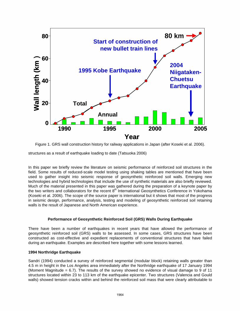
structures as a result of earthquake loading to date (Tatsuoka 2006) In this paper we briefly review the literature on seismic performance of reinforced soil structures in the field. Some results of reduced-scale model testing using shaking tables are mentioned that have been used to gather insight into seismic response of geosynthetic reinforced soil walls. Emerging new technologies and hybrid technologies that include the use of synthetic materials are also briefly reviewed. Much of the material presented in this paper was gathered during the preparation of a keynote paper by the two writers and collaborators for the recent 8th International Geosynthetics Conference in Yokohama (Koseki et al. 2006). The scope of the source paper is international but it shows that most of the progress in seismic design, performance, analysis, testing and modeling of geosynthetic reinforced soil retaining walls is the result of Japanese and North American experience.
Performance of Geosynthetic Reinforced Soil (GRS) Walls During Earthquake There have been a number of earthquakes in recent years that have allowed the performance of geosynthetic reinforced soil (GRS) walls to be assessed. In some cases, GRS structures have been constructed as cost-effective and expedient replacements of conventional structures that have failed during an earthquake. Examples are described here together with some lessons learned. 1994 Northridge Earthquake Sandri (1994) conducted a survey of reinforced segmental (modular block) retaining walls greater than 4.5 m in height in the Los Angeles area immediately after the Northridge earthquake of 17 January 1994 (Moment Magnitude = 6.7). The results of the survey showed no evidence of visual damage to 9 of 11 structures located within 23 to 113 km of the earthquake epicenter. Two structures (Valencia and Gould walls) showed tension cracks within and behind the reinforced soil mass that were clearly attributable to
80
1995 20001990 2005
Wal
l len
gth
(km
) 60
40
0
20
80 km
1995 Kobe Earthquake2004 Niigataken-ChuetsuEarthquake
Total
Annual
Start of construction of new bullet train lines
Year
80
1995 20001990 2005
Wal
l len
gth
(km
) 60
40
0
20
80 km
1995 Kobe Earthquake2004 Niigataken-ChuetsuEarthquake
Total
Annual
Start of construction of new bullet train lines
Year
Figure 1. GRS wall construction history for railway applications in Japan (after Koseki et al. 2006).
1964

the results of seismic loading. Fig. 2a shows the Valencia wall with shortened top reinforcement layers to facilitate placement of subsurface utilities. Shallow cracking at the back of the shortened length section was observed after the earthquake (Fig. 2b). Despite the shortening of these layers by the contractor, there was no visual evidence of facing movement even though peak horizontal ground accelerations as great as 0.5g were estimated at the Valencia wall site. Nevertheless, the need to increase the number and length of reinforcement layers close to the top of segmental retaining walls is predicted by current pseudo-static methods of design and has been demonstrated in reduced-scale shaking table tests. Bathurst and Cai (1995) analyzed both structures and showed that the location of cracks could be reasonably well predicted using conventional pseudo-static (Mononobe-Okabe) wedge analyses. A similar survey of three GRS walls by White and Holtz (1997) after the same earthquake revealed no visual indications of distress. Some unreinforced crib walls and unreinforced segmental walls were observed to have developed cracks in the backfill during a survey by Stewart et al. (1994). They concluded that concrete crib walls may not perform as well as more flexible GRS retaining wall systems under seismic loading. 1995 Hyogoken-Nanbu (Kobe) Earthquake Full-height concrete panel GRS walls have been built in Japan using the construction method shown in Fig. 3a. The reinforced soil mass is comprised of horizontal reinforcement layers (typically geogrids) with a flexible sandbag (or gravel gabion) facing column to contain the soil at the front of the structure during construction. The sandbag column is flexible enough that backfill soil strength and reinforcement tensile capacity is mobilized during construction. Following construction a full-height reinforced concrete facing is cast against the sandbags (Fig. 3b). An advantage of this construction method is that vertical compression of the backfill soil occurs before the hard facing is attached. The gravel gabions are stiff enough to maintain vertical alignment but flexible enough to move down with backfill soil as the soil is placed and compacted. Once the reinforced soil zone is constructed, a reinforced concrete facing 300 mm thick is cast against the wrapped gabions. Unlike reinforced soil walls constructed with the soil reinforcement layers attached directly to the hard facing, there are no down drag forces on the connections that can add parasitic tensile loads to the geosynthetic reinforcement layers. Furthermore,
H =
6.5
m
L = 5.5 m
123
45 6
78
9101112 Layer
number
L = 1.8 m
876
a) cross-section b) photograph taken after earthquake showing cracking at top of wall.
Figure 2. Valencia wall (USA) after 1994 Northridge earthquake (Bathurst and Cai 1995).
1965
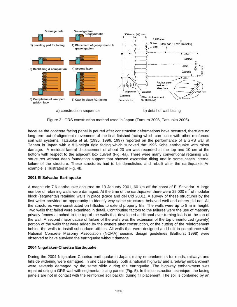
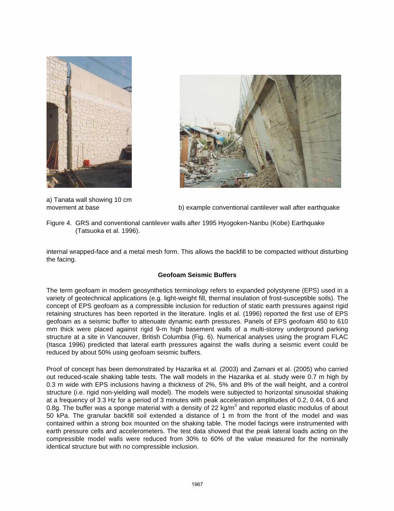
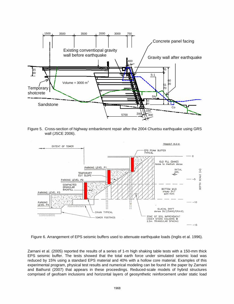
because the concrete facing panel is poured after construction deformations have occurred, there are no long-term out-of-alignment movements of the final finished facing which can occur with other reinforced soil wall systems. Tatsuoka et al. (1995, 1996, 1997) reported on the performance of a GRS wall at Tanata in Japan with a full-height rigid facing which survived the 1995 Kobe earthquake with minor damage. A residual lateral displacement of about 20 cm was recorded at the top and 10 cm at the bottom with respect to the adjacent box culvert (Fig. 4a). There were many conventional retaining wall structures without deep foundation support that showed excessive tilting and in some cases internal failure of the structure. These structures had to be demolished and rebuilt after the earthquake. An example is illustrated in Fig. 4b. 2001 El Salvador Earthquake A magnitude 7.6 earthquake occurred on 13 January 2001, 60 km off the coast of El Salvador. A large number of retaining walls were damaged. At the time of the earthquake, there were 25,000 m2 of modular block (segmental) retaining walls in place (Race and del Cid 2001). A survey of these structures by the first writer provided an opportunity to identify why some structures behaved well and others did not. All the structures were constructed on hillsides to extend property fills. The walls were up to 8 m in height. Two walls that failed were examined in detail. Contributing factors to the failures were the use of masonry privacy fences attached to the top of the walls that developed additional over-turning loads at the top of the wall. A second major cause of failure of the walls was the extension of the top unreinforced (gravity) portion of the walls that were added by the owners after construction, or the cutting of the reinforcement behind the walls to install subsurface utilities. All walls that were designed and built in compliance with National Concrete Masonry Association (NCMA) seismic design guidelines (Bathurst 1998) were observed to have survived the earthquake without damage. 2004 Niigataken-Chuetsu Earthquake During the 2004 Niigataken Chuetsu earthquake in Japan, many embankments for roads, railways and hillside widening were damaged. In one case history, both a national highway and a railway embankment were severely damaged by the same slide during the earthquake. The highway embankment was repaired using a GRS wall with segmental facing panels (Fig. 5). In this construction technique, the facing panels are not in contact with the reinforced soil backfill during fill placement. The soil is contained by an
2) Placement of geosynthetic & gravel gabion
Gravel gabionGeosynthetic
5) Completion of wrappedgabion face
4) Second layer3) Backfilling & compaction
1) Leveling pad for facing
Drainage hole
6) Cast-in-place RC facing
a) construction sequence b) detail of wall facing
Figure 3. GRS construction method used in Japan (Tamura 2006, Tatsuoka 2006).
1966
internal wrapped-face and a metal mesh form. This allows the backfill to be compacted without disturbing the facing.
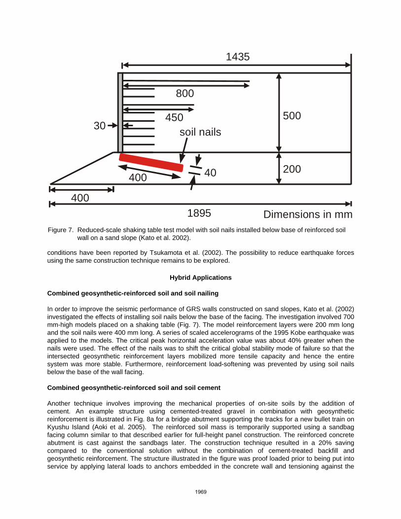
Geofoam Seismic Buffers The term geofoam in modern geosynthetics terminology refers to expanded polystyrene (EPS) used in a variety of geotechnical applications (e.g. light-weight fill, thermal insulation of frost-susceptible soils). The concept of EPS geofoam as a compressible inclusion for reduction of static earth pressures against rigid retaining structures has been reported in the literature. Inglis et al. (1996) reported the first use of EPS geofoam as a seismic buffer to attenuate dynamic earth pressures. Panels of EPS geofoam 450 to 610 mm thick were placed against rigid 9-m high basement walls of a multi-storey underground parking structure at a site in Vancouver, British Columbia (Fig. 6). Numerical analyses using the program FLAC (Itasca 1996) predicted that lateral earth pressures against the walls during a seismic event could be reduced by about 50% using geofoam seismic buffers. Proof of concept has been demonstrated by Hazarika et al. (2003) and Zarnani et al. (2005) who carried out reduced-scale shaking table tests. The wall models in the Hazarika et al. study were 0.7 m high by 0.3 m wide with EPS inclusions having a thickness of 2%, 5% and 8% of the wall height, and a control structure (i.e. rigid non-yielding wall model). The models were subjected to horizontal sinusoidal shaking at a frequency of 3.3 Hz for a period of 3 minutes with peak acceleration amplitudes of 0.2, 0.44, 0.6 and 0.8g. The buffer was a sponge material with a density of 22 kg/m3 and reported elastic modulus of about 50 kPa. The granular backfill soil extended a distance of 1 m from the front of the model and was contained within a strong box mounted on the shaking table. The model facings were instrumented with earth pressure cells and accelerometers. The test data showed that the peak lateral loads acting on the compressible model walls were reduced from 30% to 60% of the value measured for the nominally identical structure but with no compressible inclusion.
a) Tanata wall showing 10 cm movement at base b) example conventional cantilever wall after earthquake Figure 4. GRS and conventional cantilever walls after 1995 Hyogoken-Nanbu (Kobe) Earthquake
(Tatsuoka et al. 1996).
1967
Zarnani et al. (2005) reported the results of a series of 1-m high shaking table tests with a 150-mm thick EPS seismic buffer. The tests showed that the total earth force under simulated seismic load was reduced by 15% using a standard EPS material and 40% with a hollow core material. Examples of this experimental program, physical test results and numerical modeling can be found in the paper by Zarnani and Bathurst (2007) that appears in these proceedings. Reduced-scale models of hybrid structures comprised of geofoam inclusions and horizontal layers of geosynthetic reinforcement under static load
Temporary
Existing gravity - type retaining wall Before E.Q.
5700
300020003500 3500 1500 750
1500
6020 51
70
1000
400
200100
300
V= 3000
5%
Co
850
S-1
Sandstone t
shotcrete
Concrete panel facing
Existing conventional gravity wall before earthquake
-
5700
300020003500 3500 1500 750
1500
6020 51
70
1000
400
200100
300
Volume = 3000 m3
5%
Co
850
S-1
Gravity wall after earthquake
Figure 5. Cross-section of highway embankment repair after the 2004 Chuetsu earthquake using GRS
wall (JSCE 2006).
Figure 6. Arrangement of EPS seismic buffers used to attenuate earthquake loads (Inglis et al. 1996).
1968
conditions have been reported by Tsukamota et al. (2002). The possibility to reduce earthquake forces using the same construction technique remains to be explored.
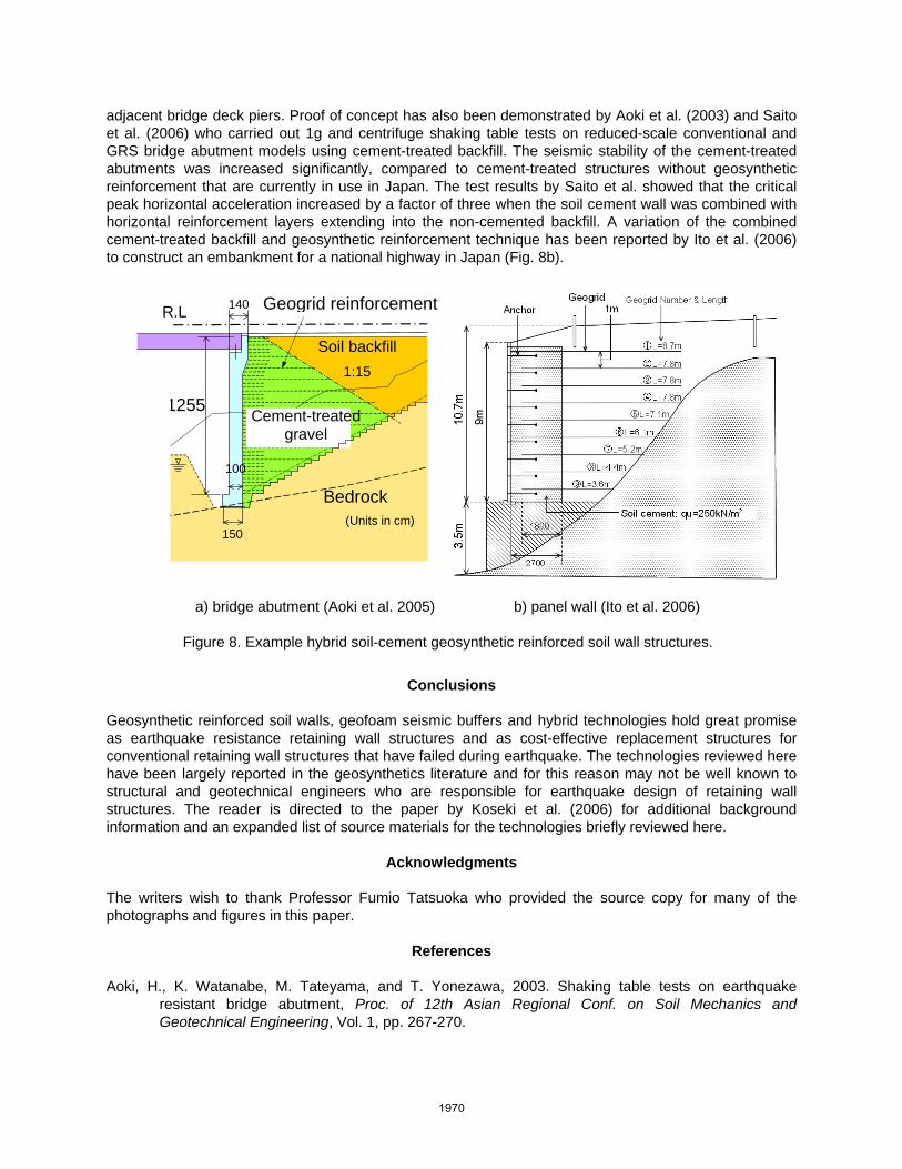
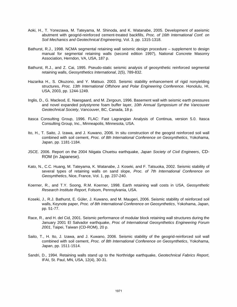
Hybrid Applications Combined geosynthetic-reinforced soil and soil nailing In order to improve the seismic performance of GRS walls constructed on sand slopes, Kato et al. (2002) investigated the effects of installing soil nails below the base of the facing. The investigation involved 700 mm-high models placed on a shaking table (Fig. 7). The model reinforcement layers were 200 mm long and the soil nails were 400 mm long. A series of scaled accelerograms of the 1995 Kobe earthquake was applied to the models. The critical peak horizontal acceleration value was about 40% greater when the nails were used. The effect of the nails was to shift the critical global stability mode of failure so that the intersected geosynthetic reinforcement layers mobilized more tensile capacity and hence the entire system was more stable. Furthermore, reinforcement load-softening was prevented by using soil nails below the base of the wall facing. Combined geosynthetic-reinforced soil and soil cement Another technique involves improving the mechanical properties of on-site soils by the addition of cement. An example structure using cemented-treated gravel in combination with geosynthetic reinforcement is illustrated in Fig. 8a for a bridge abutment supporting the tracks for a new bullet train on Kyushu Island (Aoki et al. 2005). The reinforced soil mass is temporarily supported using a sandbag facing column similar to that described earlier for full-height panel construction. The reinforced concrete abutment is cast against the sandbags later. The construction technique resulted in a 20% saving compared to the conventional solution without the combination of cement-treated backfill and geosynthetic reinforcement. The structure illustrated in the figure was proof loaded prior to being put into service by applying lateral loads to anchors embedded in the concrete wall and tensioning against the
soil nails
1435
500
800
200
450
1895
30
400
400
40
Dimensions in mm Figure 7. Reduced-scale shaking table test model with soil nails installed below base of reinforced soil
wall on a sand slope (Kato et al. 2002).
1969
adjacent bridge deck piers. Proof of concept has also been demonstrated by Aoki et al. (2003) and Saito et al. (2006) who carried out 1g and centrifuge shaking table tests on reduced-scale conventional and GRS bridge abutment models using cement-treated backfill. The seismic stability of the cement-treated abutments was increased significantly, compared to cement-treated structures without geosynthetic reinforcement that are currently in use in Japan. The test results by Saito et al. showed that the critical peak horizontal acceleration increased by a factor of three when the soil cement wall was combined with horizontal reinforcement layers extending into the non-cemented backfill. A variation of the combined cement-treated backfill and geosynthetic reinforcement technique has been reported by Ito et al. (2006) to construct an embankment for a national highway in Japan (Fig. 8b).
Conclusions Geosynthetic reinforced soil walls, geofoam seismic buffers and hybrid technologies hold great promise as earthquake resistance retaining wall structures and as cost-effective replacement structures for conventional retaining wall structures that have failed during earthquake. The technologies reviewed here have been largely reported in the geosynthetics literature and for this reason may not be well known to structural and geotechnical engineers who are responsible for earthquake design of retaining wall structures. The reader is directed to the paper by Koseki et al. (2006) for additional background information and an expanded list of source materials for the technologies briefly reviewed here.
Acknowledgments The writers wish to thank Professor Fumio Tatsuoka who provided the source copy for many of the photographs and figures in this paper.
References Aoki, H., K. Watanabe, M. Tateyama, and T. Yonezawa, 2003. Shaking table tests on earthquake
resistant bridge abutment, Proc. of 12th Asian Regional Conf. on Soil Mechanics and Geotechnical Engineering, Vol. 1, pp. 267-270.
Soil backfill
Bedrock
150
1255 Cement-treated gravel
1:15
Geogrid reinforcementR.L 140
100
(Units in cm)
a) bridge abutment (Aoki et al. 2005) b) panel wall (Ito et al. 2006)
Figure 8. Example hybrid soil-cement geosynthetic reinforced soil wall structures.
1970
Aoki, H., T. Yonezawa, M. Tateyama, M. Shinoda, and K. Watanabe, 2005. Development of aseismic abutment with geogrid-reinforced cement-treated backfills, Proc. of 16th International Conf. on Soil Mechanics and Geotechnical Engineering, Vol. 3, pp. 1315-1318.
Bathurst, R.J., 1998. NCMA segmental retaining wall seismic design procedure – supplement to design
manual for segmental retaining walls (second edition 1997), National Concrete Masonry Association, Herndon, VA, USA, 187 p.
Bathurst, R.J., and Z. Cai, 1995. Pseudo-static seismic analysis of geosynthetic reinforced segmental
retaining walls, Geosynthetics International, 2(5), 789-832. Hazarika H., S. Okuzono, and Y. Matsuo. 2003. Seismic stability enhancement of rigid nonyielding
structures, Proc. 13th International Offshore and Polar Engineering Conference. Honolulu, HI, USA, 2003, pp. 1244-1249.
Inglis, D., G. Macleod, E. Naesgaard, and M. Zergoun, 1996. Basement wall with seismic earth pressures
and novel expanded polystyrene foam buffer layer, 10th Annual Symposium of the Vancouver Geotechnical Society, Vancouver, BC, Canada, 18 p.
Itasca Consulting Group, 1996. FLAC: Fast Lagrangian Analysis of Continua, version 5.0. Itasca
Consulting Group, Inc., Minneapolis, Minnesota, USA. Ito, H., T. Saito, J. Izawa, and J. Kuwano, 2006. In situ construction of the geogrid reinforced soil wall
combined with soil cement, Proc. of 8th International Conference on Geosynthetics, Yokohama, Japan, pp. 1181-1184.
JSCE. 2006. Report on the 2004 Niigata Chuetsu earthquake, Japan Society of Civil Engineers, CD-
ROM (in Japanese). Kato, N., C.C. Huang, M. Tateyama, K. Watanabe, J. Koseki, and F. Tatsuoka, 2002. Seismic stability of
several types of retaining walls on sand slope, Proc. of 7th International Conference on Geosynthetics, Nice, France, Vol. 1, pp. 237-240.
Koerner, R., and T.Y. Soong, R.M. Koerner, 1998. Earth retaining wall costs in USA, Geosynthetic
Research Institute Report, Folsom, Pennsylvania, USA. Koseki, J., R.J. Bathurst, E. Güler, J. Kuwano, and M. Maugeri, 2006. Seismic stability of reinforced soil
walls, Keynote paper, Proc. of 8th International Conference on Geosynthetics, Yokohama, Japan, pp. 51-77.
Race, R., and H. del Cid, 2001. Seismic performance of modular block retaining wall structures during the
January 2001 El Salvador earthquake, Proc of International Geosynthetics Engineering Forum 2001, Taipei, Taiwan (CD-ROM), 20 p.
Saito, T., H. Ito, J. Izawa, and J. Kuwano, 2006. Seismic stability of the geogrid-reinforced soil wall
combined with soil cement, Proc. of 8th International Conference on Geosynthetics, Yokohama, Japan, pp. 1511-1514.
Sandri, D., 1994. Retaining walls stand up to the Northridge earthquake, Geotechnical Fabrics Report,
IFAI, St. Paul, MN, USA, 12(4), 30-31.
1971

Stewart, J.P., J.D. Bray, R.B. Seed, and N. Sitar, 1994. Preliminary report on the principal geotechnical aspects of the January 17, 1994 Northridge earthquake, UCB/EERC-94/08 Earthquake Engineering Research Center, University of California, Berkeley 1994-06, 245 p.
Tamura, Y., 2006. Lessons learned from the construction of geosynthetic-reinforced soil retaining walls
with full-height rigid facing for the last 10 years, Proc. of 8th International Conference on Geosynthetics, Yokohama, Japan, 18-22 September 2006, pp. 941-944.
Tatsuoka, F., 2006. Geosynthetic-reinforced technology for remedy works of soil structures damaged by
earthquakes and heavy rainfalls, Workshop on Retaining Structures with Geosynthetics, Indian Institute of Technology, Madras, India, 21 p.
Tatsuoka, F., M. Tateyama, and J. Koseki, 1996. Performance of soil retaining walls for railway
embankments, Soils and Foundations, Special Issue of Soils and Foundations on Geotechnical Aspects of the January 17 1995 Hyogoken-Nambu Earthquake, 311-324.
Tatsuoka, F., M. Tateyama, J. Koseki, and T. Uchimura, 1995. Geotextile-reinforced soil retaining wall
and their seismic behaviour, Proc. of 10th Asian Regional Conf. on Soil Mechanics and Foundation Engineering, Beijing, Vol. 2, pp. 26-49.
Tatsuoka, F., J. Koseki, and M. Tateyama, 1997. Performance of reinforced soil structures during the
1995 Hyogo-ken Nanbu Earthquake, Proc. of Earth Reinforcement, Balkema, Vol. 2, pp. 973-1008.
Tsukamoto, Y., K. Ishihara, H. Kon, and T. Masuo, 2002. Use of compressible expanded polystyrene
blocks and geogrids for retaining wall structures, Soils and Foundations, 42(4), 29-41. White, D.M., and R.D. Holtz, 1997. Performance of geosynthetic-reinforced slopes and walls during the
Northridge, California Earthquake of January 17, 1994, Proc. of Earth Reinforcement, Balkema, Vol. 2, pp. 965-972.
Zarnani, S., and R.J. Bathurst, 2007. Seismic load attenuation using EPS geofoam buffers in rigid wall
applications, Proc. of 9th Canadian Conference on Earthquake Engineering, Ottawa, Ontario, Canada, 10 p.
Zarnani, S., R.J. Bathurst, and A. Gaskin, 2005. Experimental investigation of geofoam seismic buffers
using a shaking table, Proc. of 2005 North American Geosynthetics Society Conference, Las Vegas, Nevada, 11 p.
1972