9a fire protection analysis 9a.1 introduction - nrc.gov · diesel fuel oil, flammable gase s,...
TRANSCRIPT
U.S. EPR FINAL SAFETY ANALYSIS REPORT
9A Fire Protection Analysis
9A.1 Introduction
The Fire Protection Analysis (FPA) evaluates the potential for occurrence of fires
within the plant and documents the capabilities of the fire protection system and
provides reasonable assurance of the capability to safely shut down the plant. The FPA
is an integral part of the process of selecting fire prevention, detection, and suppression
methods, and provides a design basis for the fire protection system. The design of the
fire protection system is described in Section 9.5.1.
The FPA is performed for each fire area using the methodology addressed in
Section 9A.2. The methodology follows the guidance of RG 1.189. The results of the
analysis are provided in Section 9A.3.
Fires are expected to occur over the life of a nuclear power plant and should be treated
as anticipated operational occurrences as defined in Appendix A to 10 CFR Part 50.
Requirements for protection against radiation during normal operations appear in 10
CFR Part 20. Anticipated operational occurrences of fires should not result in
unacceptable radiological consequences, and the exposure criteria of 10 CFR Part 20
apply. Prevention of a radiological release that could result in a radiological hazard to
the public, environment, or plant personnel becomes the primary objective during
plant shutdown and decommissioning.
9A.1.1 Regulatory Bases
The regulatory bases and requirements applicable to the U.S. EPR design certification
have been previously established, and are only restated in the FPA for completeness.
10 CFR 52.48 specifies, in part, that, “Applications filed under this subpart will be
reviewed for compliance with the standards set out in 10 CFR part 50 and its
appendices.”
GDC 3 of Appendix A to 10 CFR Part 50 states:
“Structures, systems, and components important to safety shall be designed and located
to minimize, consistent with other safety requirements, the probability and effect of
fires and explosions. Noncombustible and heat resistant materials shall be used
wherever practical throughout the unit, particularly in locations such as the
containment and control room. Fire detection and fighting systems of appropriate
capacity and capability shall be provided and designed to minimize the adverse effects
of fires on structures, systems, and components important to safety. Firefighting
systems shall be designed to assure that their rupture or inadvertent operation does not
significantly impair the safety capability of these structures, systems, and
components.”
Tier 2 Revision 5 Page 9A-1
U.S. EPR FINAL SAFETY ANALYSIS REPORT
Additionally, 10 CFR 50.34(h) requires new reactor license applications to include an
evaluation of the facility against the current Standard Review Plan (SRP) guidance.
The applicable SRP guidance is specified in Section 9.5.1 of NUREG-0800
(Reference 1). Reference 1 describes the areas of review, acceptance criteria, and
review procedure for NRC review of nuclear power plant fire protection programs.
Reference 1 in turn invokes RG 1.189 for methods acceptable to the NRC to
demonstrate compliance with the SRP review criteria. In addition to the guidance
specified in RG 1.189, Section 9.5.1 of Reference 1 also invokes SECY-90-016
(Reference 2) for additional NRC fire protection requirements applicable to
evolutionary reactor designs.
9A.1.2 Defense-In-Depth
The objective of the overall Fire Protection Program is to implement a defense-in-
depth strategy to achieve and maintain a high degree of plant safety. This strategy is
accomplished by achieving and maintaining a balance between the following:
● Preventing fires from occurring.
● The capability to rapidly detect, control, and promptly extinguish those fires that do occur.
● Adequate protection for safety-related structures, systems, and components (SSC) so that a fire that is not promptly extinguished by fire suppression activities will not prevent safe shutdown of the plant or result in release of radioactive materials to the environment.
The programmatic elements used by the FPA to implement the defense-in-depth
strategy are:
● Document and assess the impact of in situ and transient fire hazards on a fire area basis throughout the facility, including potential effects on safe shutdown capability, effects of fire suppression activities, and applicable risk insights from the fire probabilistic fire risk assessment.
● Specify measures for fire prevention, fire detection, fire suppression, and fire confinement.
● Minimize the potential for a fire or fire-related event to place the plant in an unrecoverable condition, cause a release of radioactive materials, or result in radiological exposure to onsite and offsite personnel.
● Specify measures that will provide reasonable assurance that one success path of safe shutdown capability will be available under credible postfire conditions.
Tier 2 Revision 5 Page 9A-2
U.S. EPR FINAL SAFETY ANALYSIS REPORT
9A.1.3 Scope
The scope of the FPA consists of the comprehensive assessment of the fire or explosion
hazards for the plant structures in the following list, including a description of the fire
protection defense-in-depth features provided to minimize the consequences of such
an event.
● Reactor Building (UJA / UJB).
● Safeguard Buildings (1-4 UJH / 1-4 UJK).
● Fuel Building (UFA).
● Nuclear Auxiliary Building (UKA).
● Radioactive Waste Processing Building (UKS).
● Emergency Power Generating Buildings (1-4 UBP).
● Essential Service Water Pump Structures (1-4 UQB) and Cooling Tower Structures (1-4 URB).
● Access Building (UKE).
9A.2 Fire Protection Analysis Methodology
9A.2.1 General Design Criteria
As described in Section 9A.1, the fire protection performance objectives for design
certification of the U.S. EPR are:
● Provide reasonable assurance that one success path of SSC will remain free of fire damage so that hot standby and cold shutdown conditions can be achieved without crediting plant or system repair activities.
● Minimizing and controlling the release of radioactivity to the environment.
To meet these performance objectives, Reference 2 specifies the following design
criteria:
“Therefore, the evolutionary ALWR designers must ensure the safe shutdown can be
achieved, assuming all equipment in any one fire area is rendered inoperable by fire
and that re-entry into the fire area for repairs and operator actions is not possible.
Because of its physical configuration, the control room is excluded from this approach,
provided an independent alternative shutdown capability that is physically and
electrically independent of the control room is included in the design. Evolutionary
ALWR designers must provide fire protection for redundant shutdown systems in the
reactor containment building that will ensure, to the extent practicable, that one
Tier 2 Revision 5 Page 9A-3
U.S. EPR FINAL SAFETY ANALYSIS REPORT
shutdown division will be free of fire damage. Additionally, the evolutionary ALWR
designers must ensure that smoke, hot gases, or the fire suppressant will not migrate
into other fire areas to the extent that they could adversely affect safe shutdown
capabilities, including operator manual actions.”
Based on the previously mentioned criteria, for the U.S. EPR, redundant divisions of
safe shutdown systems, components, and cables, including associated circuits (e.g.,
safety-related, non-safety-related, Class 1E and non-Class 1E), whose failure could
affect or prevent postfire safe shutdown capability, should not be located within the
same fire area. The exceptions are the control room, because of provision of physically
and electrically independent alternative shutdown capability, and the Reactor
Building, because of provision of fire protection defense-in-depth features that provide
reasonable assurance, to the extent practicable, that one success path of SSC necessary
to achieve safe shutdown will remain free of fire damage.
9A.2.2 Specific Elements
To meet this design criterion, the following methodology is employed.
1. In accordance with GDC 3, structures, systems and components important to safety must be designed and located to minimize the probability and effect of fires and explosions. The requirements of GDC 3 are met, in part, by compartmentation of the plant into separate fire areas. Specifically, based on the hazards present and the need for physical separation of SSC important to safety, the plant is segregated into separate fire areas by passive, fire-rated structural barriers (e.g., walls, floors, and ceilings). In some instances (e.g., Reactor Building), a fire area is sub-divided into fire zones based on physical separation, location of plant equipment, or for FPA purposes. These fire areas and zones serve the primary purpose of confining the effects of fires to a single compartment or area, thereby minimizing the potential for adverse effects from fires on redundant SSC important to safety. Outside of the control room and the Reactor Building, each of the redundant divisions of emergency core cooling are separated by three hour rated structural fire barriers.
2. Materials used in plant construction are noncombustible or heat resistant to the extent practicable in accordance with GDC 3. Walls, floors, roofs, including structural materials, suspended ceilings, thermal insulation, radiation shielding materials, and soundproofing and interior finish are noncombustible or meet applicable qualification test acceptance criteria unless otherwise justified. Concealed spaces are devoid of combustibles unless otherwise justified.
3. The plant layout also provides reasonable assurance that adequate means of access to all plant areas is provided for manual fire suppression activities and allow safe access and egress for personnel. The layout and travel distances of access and egress routes meet the intent of NFPA 101 (Reference 3) to the extent practicable, unless otherwise justified. Potential delays in plant access or egress due to security locking systems are considered.
Tier 2 Revision 5 Page 9A-4
U.S. EPR FINAL SAFETY ANALYSIS REPORT
4. The in situ plant equipment and components, including electrical cables, housed within each fire area are considered. Any safety-related SSC located within the fire area are considered.
5. In situ fire and explosion hazards associated with plant operations, maintenance, and refueling activities within the fire area are identified (e.g., cables, lube oil, diesel fuel oil, flammable gases, chemicals, building materials, and interior finish). In developing postulated fire scenarios for each fire area, the FPA considers the quantity and continuity of combustible materials, susceptibility of the materials to ignition, heat of combustion, heat release rates (HRR), and potential for fire spread.
In the event that a fire area could be subject to potentially explosive environments from flammable gases or other potentially energetic sources (e.g., chemical treatment systems, ion exchange columns), explosion-prevention features and measures are provided.
External exposure hazards are identified (e.g., flammable and combustible liquid or gas storage, auxiliary boiler units, natural vegetation) that could potentially expose safety-related SSC to fire effects (i.e., heat, flame, smoke). Wildfire hazards are addressed if the potential for damage to safety-related SSC exists.
6. The credible in situ ignition sources within the fire area are identified. The FPA classifies ignition sources as common or atypical and assign potential fire severity levels on a generic basis using predefined guidance. Most in situ ignition sources are of the common type, which include electrical switchgear cabinets, general electrical and control cabinets, electric motors, pumps (i.e., reactor coolant pumps, feedwater pumps, and other pumps), diesel generators, air compressors, battery banks, boiler heating units, electric dryers, heating, ventilation, air conditioning (HVAC) subsystem components, and others.
Atypical sources of ignition include arcing electrical faults, hydrogen storage tanks, hydrogen piping, turbine generator exciter hydrogen, outdoor oil-filled transformers, and liquid fuels (i.e., spills). Because of their nature, fires associated with atypical ignition sources are not assigned a generic intensity level.
Most anticipated fires will involve the common in situ ignition sources as represented by the equipment and components typically found in nuclear power plants. Such fires can be assessed using a fixed fire intensity (i.e., HRR) level for the given fire ignition source. However, consideration of a fixed fire intensity level for a given ignition source may not adequately consider the potential for low-likelihood, high intensity fires. NUREG/CR-6850, (Reference 4) addressed this concern by assigning a ranking of two HRR values. The first value assigned is the 75th percentile fire intensity. This means that 75 percent of the fires involving a given ignition source would reach an intensity no greater than the cited fire intensity (absent the fire propagating to any secondary combustibles). The second HRR value is the 98th percentile value, which is intended to represent a high-confidence fire intensity value, which based on the industry guidance cited, is expected to bound the vast majority of fires involving a given ignition source. Table 9A-1—Predefined Severities for Common Plant Ignition Source Fires
Tier 2 Revision 5 Page 9A-5
U.S. EPR FINAL SAFETY ANALYSIS REPORT
provides the predefined HRR values associated with common plant ignition sources.
Based on the in situ fire or explosion hazards and sources of ignition present within the fire area under consideration, postulated fire scenarios are developed and assessed. The FPA then assigns a hazard classification to each fire area. This classification is used as a broad characterization of the overall hazard assessment of each fire area. The classification system uses the same category and naming hierarchy as NFPA 13 (Reference 5) for classification of building occupancies. However, as used herein, these classifications are only intended to be a simplified reflection of the positive correlation between fire severity and the quantity of fuel available to support combustion and the thermal properties (e.g., HRR) of the fuel. The HRR values shown for each fire area hazard classification are only intended to represent the level of intensity that would generally be expected for a fire of this type. These HRR values are not used as a basis for determining worst-case fire scenarios. The classifications used are defined as follows:
− Light Hazard – areas where, in combination or separately, the quantity or combustibility of materials are generally low, and fires with relatively low rates of heat release (e.g., 70 kW) are expected.
− Ordinary Hazard (OH) (Group 1) – areas where the combustibility of materials is generally low, the quantity of materials is moderate (without large concentrations), and fires with moderate rates of heat release (e.g., 200 kW) are expected.
− Ordinary Hazard (OH) (Group 2) – areas where the quantity and combustibility of materials are moderate to high (segregated large concentrations may exist), and fires with moderate to high rates of heat release (e.g., 650 kW) are expected.
− Extra Hazard (EH) (Group 1) – areas where the quantity and combustibility of materials are very high, with materials present that have the potential to result in rapidly developing fires with high rates of heat release (e.g., 2 MW), but with little or no combustible or flammable liquids present.
− Extra Hazard (EH) (Group 2) – areas with moderate to substantial amounts of combustible or flammable liquids present, which would result in fires having very high rates of heat release (e.g., 10 MW).
The predefined higher and lower HRR values associated with common ignition source fires and the corresponding FPA hazard classifications are provided in Table 9A-1.
7. Based on the type and nature of the plant equipment located in the area, the plant activities normally performed in the area, and the frequency of those activities, the FPA provides a transient hazard level (THL) assessment of transient fire hazards into the fire area analysis. A THL-1 determination generally reflects no need for detailed assessment of transient fire hazards. Depending on the type and quantity of in situ hazards within the area and its FPA hazard classification, a THL-2
Tier 2 Revision 5 Page 9A-6

U.S. EPR FINAL SAFETY ANALYSIS REPORT
determination may or may not reflect the need for detailed assessment of transient fire hazards. A THL-3 determination generally reflects the need for detailed assessment of transient fire hazards within the area analysis. In such cases, the material type, quantity, and associated thermal properties comprising the transient hazard package is evaluated. More than one type of transient hazard source may apply to a given fire area. Section 9A.2.3.3 provides additional information regarding the transient fire hazard determination process.
Based on compartmentation of the plant by three hour rated structural fire barriers,
additional fire protection features (e.g., fire detection system capability, fixed fire
suppression system capability, electrical raceway fire barrier systems) are generally not
required in order to provide adequate separation of redundant trains of safe shutdown
systems, components, and cables. However, for provision of fire protection features,
regulatory requirements and regulatory guidance take precedence. Risk-informed,
performance-based methods, or other quantitative/computational methods or tools are
not utilized to determine where fire detection and suppression systems will or will not
be installed. However, where fire detection and suppression systems are provided in
accordance with regulatory guidance, recognized fire protection engineering practices,
methods and analytical tools, such as those promulgated by NUREG-1805 and
NUREG-1824 may be used to assess the performance capability of such systems.
8. Based on the previously mentioned considerations, suitable fire protection defense-in-depth features are specified for all plant fire areas.
The fire protection features provided (e.g., fire barriers and closure devices, fire detection systems, fire suppression systems and equipment) are designed and installed in accordance with applicable regulatory guidance, codes and NFPA standards. Deviations from the above requirements are justified. See Section 9.5.1 for further information regarding fire protection features.
9. Appropriate manual fire suppression capability (i.e., hydrants, standpipe and hose systems, and portable fire extinguishers) are specified and described for each plant fire area.
10. Pursuant to GDC 3, the potentially disabling effects of fire suppression systems, due to normal or inadvertent operation, on SSC important to safety are described for each fire area.
11. The FPA describes the means provided to ventilate, exhaust, or isolate each fire area. Additionally, in accordance with Reference 2, the ventilation system design provides reasonable assurance that smoke, hot gases, and fire suppressants do not migrate into other fire areas to the extent that they could adversely affect safe shutdown capabilities, including operator manual actions. See Section 9.5.1 for further information regarding the ventilation system design.
12. For each fire area, the capability to protect safety-related SSC from flooding associated with automatic and manual fire suppression activities, including inadvertent operation or fire suppression system failure, is considered. The effects
Tier 2 Revision 5 Page 9A-7

U.S. EPR FINAL SAFETY ANALYSIS REPORT
of floor drains on the ability of total flooding gaseous fire suppression systems to achieve and maintain agent concentration upon discharge is considered for applicable fire areas.
In fire areas containing flammable or combustible liquids, the measures are provided to minimize the potential for fire propagation via the drainage system.
13. Emergency lighting required to support fire suppression activities and postfire safe shutdown operations, including access and egress routes to such locations, is described.
14. Plant communication systems, including hardwired and radio systems to provide effective communications between plant personnel performing safe shutdown operations, fire brigade personnel, and the main control room (MCR) or alternative shutdown location, are described.
9A.2.3 Assumptions
9A.2.3.1 General
1. The loss of function of systems used to mitigate the consequences of design basis accidents under postfire conditions does not necessarily impact public safety. The need to limit fire damage to systems required to achieve and maintain safe shutdown conditions is greater than the need to limit fire damage to those systems required to mitigate the consequences of design basis accidents.
2. The systems used for alternative shutdown do not need to be designed to Seismic Category I criteria, single failure criteria, or other design basis accident criteria, except the portions of these systems that interface with or impact safety systems.
3. Fire damage to safe shutdown equipment or fires with the potential to result in release of radioactive materials to the environment is assessed on the basis of a single fire, including an exposure fire. An exposure fire is a fire in a given area that involves either in situ or transient combustibles and has the potential to affect SSC important to safety or radioactive materials located in or adjacent to that same area. The effects of such fire (e.g., smoke, heat, ignition) can adversely affect those SSC important to safety. Thus, if safe shutdown equipment associated with multiple success paths were located in the same fire area, a fire involving one success path of safe shutdown equipment could constitute an exposure fire to the remaining success paths, and a fire involving combustibles other than a redundant success path may constitute an exposure fire to redundant success paths located in the same area.
4. Redundant systems required for design basis accident consequence mitigation, but not required for fire safe shutdown may be damaged by a single exposure fire. The most stringent limitation for fire damage applies toward those systems that are required for both safe shutdown and design basis accident mitigation.
5. The fire event considered for alternative shutdown is a postulated fire in a specific fire area containing redundant safe shutdown cables or equipment where it has
Tier 2 Revision 5 Page 9A-8

U.S. EPR FINAL SAFETY ANALYSIS REPORT
been determined that fire protection systems and features can not be provided to provide reasonable assurance that safe shutdown capability will be preserved. For the U.S. EPR, areas requiring alternative shutdown are limited to the control room.
6. It is assumed that a fire may occur at any time, but is not postulated to occur simultaneously with plant accidents or with severe natural phenomena (e.g., floods or high winds). However, severe natural phenomena (e.g., earthquakes) may initiate a fire event and are considered in evaluating the design capability of fire protection systems and features.
7. In evaluating the capability to accomplish postfire safe shutdown, offsite power may or may not be available and consideration is given to both cases. However, loss of offsite power need not be considered for a fire in non-alternative shutdown areas (i.e., outside of the control room) if it can be shown that offsite power can not be lost because of a fire in that area.
8. Alternative shutdown capability accommodates postfire conditions where offsite power is available and where offsite power is not available for 72 hours. In evaluating safe shutdown circuits, including associated circuits, the availability of uninterrupted power (i.e., offsite power available) may impact the ability to control the safe shutdown of the plant by increasing the potential for associated circuit interactions resulting from fire damage to energized power and control circuits.
9. Intentional station blackout (SBO) is not relied upon to mitigate potential fire damage to safe shutdown systems or associated circuits.
9A.2.3.2 Ignition Sources
1. Self-ignition of electrical cables that are qualified in accordance with a nationally recognized standard fire test methodology, such as IEEE Std 1202 (Reference 6) is not considered credible due to the protective devices (e.g., fuses, circuit breakers) provided and analyzed to be properly sized. On this basis, qualified electrical cables are considered as potential damage targets, but not ignition sources. Accordingly, any type of electrical cabling routed within metal conduit are considered as potential damage targets, but do not contribute to fire growth and spread, and therefore are not considered as ignition sources.
2. Hot work is only considered as a transient ignition source where performance of hot work is consistent with the plant equipment and normal activities to be performed within the fire area.
9A.2.3.3 Transient Fire Hazards
1. THL-1 applies to fire areas that are normally closed to any type of traffic, are not visited often (e.g., not more than once per week), are not occupied during normal plant operations, and where maintenance activities would generally be disallowed during at-power modes of plant operation. Such fire areas should also be subject to
Tier 2 Revision 5 Page 9A-9
U.S. EPR FINAL SAFETY ANALYSIS REPORT
administrative controls that disallow leaving or storing unattended transient combustible materials. Examples of THL-1 areas include:
− Areas where the exposed combustibles are limited to qualified cables, access is strictly controlled, and administrative controls prevent unattended transient combustibles.
− Cable vaults and other areas having controlled access.
− MCR (Exception: continuous occupancy of the MCR is not taken as indicative of a higher transient fire likelihood because extraordinary vigilance is expected for this area).
− Reactor Building.
2. THL-2 applies to fire areas that either have occasional to frequent foot traffic (e.g., not more than once per shift and the area is not a regular access transit pathway) or are occasionally, but not continuously occupied during normal plant operations. Modest storage of transient combustible materials may be allowed. THL-2 would also apply to a fire area where maintenance activities are allowed at-power modes of plant operation, but such maintenance activities are subject to administrative controls (e.g., activity-specific permit process or other combustible controls program measures) and are a relatively rare occurrence (e.g., once per operating year). Examples of THL-2 areas or processes include:
− Areas not normally locked are not used as a passage to other areas of the plant (e.g., a DC power distribution panel room at the end of a corridor).
− Normally unlocked areas that only a few plant personnel may enter once or twice per shift.
− Areas that normal plant operations may infrequently involve personnel occupation for up to several hours.
− Areas where the predominate exposed combustibles are qualified cables, but may contain other plant components.
− Areas where materials may be stored on a temporary basis (e.g., to perform a maintenance or repair activity on nearby equipment). However, such storage should be infrequent rather than routine.
− Areas where routine maintenance or repair activities (e.g., pump lube oil change-out or motor bearing maintenance) may result in the introduction of transient combustibles or ignition sources on a relatively common basis (e.g., two or more times per year) while the plant is at-power.
− Most pump rooms and areas within the Nuclear Auxiliary Building.
− Most switchgear areas and battery rooms, depending on the frequency of maintenance activities.
Tier 2 Revision 5 Page 9A-10

U.S. EPR FINAL SAFETY ANALYSIS REPORT
3. THL-3 generally applies to fire areas that have heavy foot traffic, are frequently or continuously occupied, where transient combustibles are typically stored, where plant refuse is routinely gathered in substantive quantities for collection, where ignition sources are frequently brought into the area, and where maintenance activities are common during normal plant operation. Examples of THL-3 areas include:
− Plant areas where personnel are present for a large fraction of the time. Paper-based items (e.g., letters, reports, computer printouts.) are brought in and maintained in the area. Small electrical tools or appliances (e.g., hot plates, portable heaters, microwave ovens, coffee pots) may frequently be used in the area. Also included are health physics access control areas, break room areas, any area used for food preparation, and security stations. While not applicable to the MCR, portions of the control room complex, such as kitchen or security areas may be THL-3.
− Areas where smoking is not prohibited, or where there is evidence of smoking.
− Areas with open trash cans that routinely contain substantive quantities of general trash.
− Areas where radiation protection gear (e.g., jump suits, gloves, boots) are stored or collected including turn-out and change-out areas.
− Areas used for storage (permanent or temporary) of flammable or combustible liquids or gases.
− Staging areas where items are repaired or constructed before they are taken to other parts of the plant for use or installation.
− Areas where materials are prestaged in anticipation of a planned outage.
− Truck loading and unloading bays.
− Areas where hot work is relatively common during at-power plant operations.
− Areas within the diesel generator areas, intake structures, and the Radiation Waste Building.
9A.3 Fire Area-by-Fire Area Evaluation
The FPA is performed on a fire area by fire area basis for the following plant
structures:
● Reactor Building (UJA / UJB).
● Safeguard Buildings (1-4 UJH / 1-4 UJK).
● Fuel Building (UFA).
Tier 2 Revision 5 Page 9A-11

U.S. EPR FINAL SAFETY ANALYSIS REPORT
● Nuclear Auxiliary Building (UKA).
● Radioactive Waste Processing Building (UKS).
● Emergency Power Generating Buildings (1-4 UBP).
● Essential Service Water Pump Structures (1-4 UQB) and Cooling Tower Structures (1-4 URB).
● Access Building (UKE).
9A.3.1 Reactor Building
9A.3.1.1 Fire area FA-UJA-01 (Table 9A-2, Column 1)
Fire area FA-UJA-01 is the entire Reactor Containment Building from elevation -20
feet through elevation +94 feet.
Partial area automatic smoke and/or heat detection is provided over the reactor
coolant pumps (RCP) and at the elevator lobby. Manual fire alarm stations are
provided at the access to the exit stairwell.
A manually operated fixed water spray/deluge system is provided on the reactor
coolant pumps.
The adequacy of the fire protection features provided is sufficient to prevent a fire
originating within fire area FA-UJA-01 from affecting adjacent fire areas.
This fire area is not normally occupied during normal plant operations. The egress
route from this area in the event of a fire is via the access to personnel airlock [
]
9A.3.1.2 Fire Area FA-UJB-01 (Table 9A-2, Column 1A)
Fire Area FA-UJB-01 is the entire reactor annulus from elevation -20 feet through
elevation +94 feet. The fire area is further subdivided into four fire zones, each zone
containing one of the four divisions of cabling required for post-fire safe shutdown.
Partial area automatic smoke detection is provided.
The adequacy of the fire protection features provided is sufficient to prevent a fire
originating in one of the fire zones from affecting adjacent fire zones in FA-UJB-01 or
adjacent fire areas.
This fire area is not normally occupied during normal plant operations. The egress
route from this area, in the event of a fire, is via the access to personnel airlock [ ]
Tier 2 Revision 5 Page 9A-12
U.S. EPR FINAL SAFETY ANALYSIS REPORT
9A.3.2 Safeguard Building Division 1
9A.3.2.1 Fire area FA-1UJH-01 (Table 9A-2, Column 2)
Fire area FA-1UJH-01 is the [ ] staircase of Safeguard Building Division 1 [
]
Automatic fire detection is NOT provided for this area. Manual fire alarm stations are
provided at the access to the exit stairwells.
The adequacy of the fire protection features provided is sufficient to prevent a fire
originating within fire area FA-1UJH-01 from affecting adjacent fire areas.
This fire area is frequently occupied during normal plant operations. This area is used
as the primary access and egress path into and between elevations of Safeguard
Building Division 1. Egress routes from this area in the event of fire are via the
staircase located in the [ ] Safeguard Building Division 1 and the
door to the outside [ ] or to Safeguard Building Division 2 and 3 via the door at [ ] of the
passageway, or to the Fuel Building via the door at [ ] of the
passageway.
9A.3.2.2 Fire area FA-1UJH-02 (Table 9A-2, Column 3)
Fire area FA-1UJH-02 is the elevator shaft and equipment room associated with
Safeguard Building Division 1 and extends from elevation -31 feet up to elevation +81
feet.
Area wide automatic heat detection is provided for the elevator equipment and smoke
detection in the lobby area.
The adequacy of the fire protection features provided is sufficient to prevent a fire
originating within fire area FA-1UJH-02 from affecting adjacent fire areas.
This fire area is frequently occupied during normal plant operations. This area is used
as a primary travel path between elevations of Safeguard Building Division 1. In the
event of a fire, egress is via the staircase (fire area FA-1UJH-01) located in the [ ] Safeguard Building Division 1.
Tier 2 Revision 5 Page 9A-13
U.S. EPR FINAL SAFETY ANALYSIS REPORT
9A.3.2.3 Fire area FA-1UJH-03 (Table 9A-2, Column 4)
Fire area FA-1UJH-03 includes mechanical systems, maintenance areas, storage areas,
and corridors and other general areas in Safeguard Building Division 1, and extends
from elevation -31 feet up to elevation +96 feet.
Area wide automatic smoke detection is provided throughout and manual fire alarm
stations are provided at the access to exit stairwell.
The adequacy of the fire protection features provided is sufficient to prevent a fire
originating within fire area FA-1UJH-03 from affecting adjacent fire areas.
This fire area is frequently occupied during normal plant operations. The egress route
from this area in the event of a fire is via the staircase (fire area FA-1UJH-01) located
in the [ ] Safeguard Building Division 1, or by using the
interconnecting passageway at elevation zero.
9A.3.2.4 Fire area FA-1UJH-04 (Table 9A-2, Column 5)
Fire area FA-1UJH-04 is located in Safeguard Building Division 1 and extends from
elevation -16 feet up to elevation +27 feet.
Area wide automatic smoke detection is provided throughout.
The adequacy of the fire protection features provided are sufficient to prevent a fire
originating within fire area FA-1UJH-04 from affecting adjacent fire areas.
This fire area is occasionally occupied during normal plant operations. The egress
route from this area in the event of a fire is via the staircase (fire area FA-1UJH-01)
located in the [ ] Safeguard Building Division 1.
9A.3.2.5 Fire area FA-1UJH-05 (Table 9A-2, Column 6)
Fire area FA-1UJH-05 is [ ] located at the +15 elevation of Safeguard
Building Division 1.
Area wide automatic smoke detection is provided throughout.
The adequacy of the fire protection features provided is sufficient to prevent a fire
originating within fire area FA-1UJH-05 from affecting adjacent fire areas.
This fire area is occasionally occupied during normal plant operations. The egress
route from this area in the event of a fire is via the staircase (fire area FA-1UJH-01)
located in the [ ] Safeguard Building Division 1 or by using the
Tier 2 Revision 5 Page 9A-14
U.S. EPR FINAL SAFETY ANALYSIS REPORT
escape ladder (fire area FA-1UJH-01) located in [ ] Safeguard
Building Division 1.
9A.3.2.6 Fire area FA-1UJH-06 (Table 9A-2, Column 7)
Fire area FA-1UJH-06 is [
] located at elevation +27 of Safeguard Building Division 1.
Area wide automatic smoke detection is provided throughout and manual fire alarm
stations are provided at the access to exit stairwell.
The adequacy of the fire protection features provided are sufficient to prevent a fire
originating within fire area FA-1UJH-06 from affecting adjacent fire areas.
This fire area is occasionally occupied during normal plant operations. The egress
route from this area in the event of a fire is via the staircase (fire area FA-1UJH-01)
located in the [ ] Safeguard Building Division 1, or by using the
escape ladder located in the [ ] Safeguard Building Division 1.
9A.3.2.7 Fire area FA-1UJH-07 (Table 9A-2, Column 8)
Fire area FA-1UJH-07 is located in Safeguard Building Division 2 and extends from
elevation +55 feet up to elevation +81 feet.
Area wide automatic smoke detection is provided throughout Level Instrument rooms.
The adequacy of the fire protection features provided is sufficient to prevent a fire
originating within fire area FA-1UJH-07 from affecting adjacent fire areas.
This fire area is frequently occupied during normal plant operations. The egress route
from this area in the event of a fire is via the staircase (fire area FA-2UJH-01) located
in the [ ] Safeguard Building Division 2.
9A.3.2.8 Fire area FA-1UJH-08 (Table 9A-2, Column 9)
Fire area FA-1UJH-08 is located in Safeguard Building Division 2 at elevation +69 feet.
Partial area automatic heat detection is provided within the HVAC units.
The adequacy of the fire protection features provided is sufficient to prevent a fire
originating within fire area FA-1UJH-08 from affecting adjacent fire areas.
This fire area is frequently occupied during normal plant operations. The egress route
from this area in the event of a fire is via the staircase (fire area FA-2UJH-01) located
in the [ ] of Safeguard Building Division 2.
Tier 2 Revision 5 Page 9A-15

U.S. EPR FINAL SAFETY ANALYSIS REPORT
9A.3.3 Safeguard Building Division 2
9A.3.3.1 Fire area FA-2UJH-01 (Table 9A-2, Column 10)
Fire area FA-2UJH-01 extends from elevation -31 feet to elevation +69 feet of
Safeguard Building Divisions 2 and 3 and includes the [ ] staircases,
interconnecting passageways at different elevations, and escape staircases located at
the [ ]of Safeguard Building Divisions 2 and 3.
Automatic fire detection is NOT provided for this area. Manual fire alarm stations are
provided at the access to the exit stairwells.
The adequacy of the fire protection features provided is sufficient to prevent a fire
originating within fire area FA-2UJH-01 from affecting adjacent fire areas.
This fire area is frequently occupied during normal plant operations. This area is used
as the primary access and egress path through Safeguard Building Divisions 2 and 3.
9A.3.3.2 Fire area FA-2UJH-02 (Table 9A-2, Column 11)
Fire area FA-2UJH-02 is the elevator shaft and equipment room that extends from
elevation -31 feet to elevation +69 feet of Safeguard Building Divisions 2 and 3.
Area wide automatic heat detection is provided for the elevator equipment and smoke
detection in the lobby area.
The adequacy of the fire protection features provided is sufficient to prevent a fire
originating within fire area FA-2UJH-02 from affecting adjacent fire areas.
This fire area is frequently occupied during normal plant operations. This area is used
as a primary travel path between elevations of Safeguard Building Divisions 2 and 3.
In the event of a fire in this area, egress is via the staircase (fire area FA-2UJH-01)
located in the [ ] Safeguard Building Divisions 2 and 3.
9A.3.3.3 Fire area FA-2UJH-03 (Table 9A-2, Column 12)
Fire area FA-2UJH-03 is located in Safeguard Building Divisions 2 and 3 and extends
from elevation -31 feet to elevation +69 feet.
Automatic fire detection or manual fire alarm stations are NOT provided for this area.
The adequacy of the fire protection features provided is sufficient to prevent a fire
originating within fire area FA-2UJH-03 from affecting adjacent fire areas.
The majority of the areas within this fire area are frequently occupied during normal
plant operations. An approved means of egress is not necessarily provided out of the
Tier 2 Revision 5 Page 9A-16
U.S. EPR FINAL SAFETY ANALYSIS REPORT
ventilation shafts, as they are not occupied or accessible areas. However, the occupied
areas are provided with a means of egress, by way of the exit staircase, [
]
9A.3.3.4 Fire area FA-2UJH-04 (Table 9A-2, Column 13)
Fire area FA-2UJH-04 is located at elevations +15 and +27 feet of Safeguard Building
Divisions 2 and 3.
Area wide automatic smoke detection is provided throughout and manual fire alarm
stations are provided at the access to exit stairwell.
The adequacy of the fire protection features provided are sufficient to prevent a fire
originating within fire area FA-2UJH-04 from affecting adjacent fire areas.
This fire area is frequently occupied during normal plant operations. This area is used
as the primary access and egress path into Safeguard Building Divisions 2 and 3.
9A.3.3.5 Fire area FA-2UJH-05 (Table 9A-2, Column 14)
Fire area FA-2UJH-05 [
] at elevation +27 feet of Safeguard Building Divisions 2 and 3.
Area wide automatic smoke detection is provided throughout and manual fire alarm
stations are provided at the access to exit stairwell.
The adequacy of the fire protection features provided is sufficient to prevent a fire
originating within fire area FA-2UJH-05 from affecting adjacent fire areas.
This fire area is frequently occupied during normal plant operations. In the event of a
fire in this area, egress is via [ ] staircases in
Safeguard Building Divisions 2 and 3.
9A.3.3.6 Fire area FA-2UJH-06 (Table 9A-2, Column 15)
Fire area FA-2UJH-06 is [ ] located at elevation +39 of Safeguard
Building Divisions 2 and 3.
Area wide automatic heat detection is provided throughout the battery room in
addition to flammable gas detection.
The adequacy of the fire protection features provided is sufficient to prevent a fire
originating within fire area FA-2UJH-06 from affecting adjacent fire areas.
Tier 2 Revision 5 Page 9A-17

U.S. EPR FINAL SAFETY ANALYSIS REPORT
This fire area is frequently occupied during normal plant operations. In the event of a
fire in this area, egress is via [ ]
Safeguard Building Divisions 2 and 3.
9A.3.3.7 Fire area FA-2UJH-07 (Table 9A-2, Column 16)
Fire area FA-2UJH-07 is located in Safeguard Building Division 2 and extends from
elevation +53 feet up to elevation +69 feet.
Area wide automatic smoke detection is provided throughout the control room and
within the cabinets/consoles.
A manually actuated gaseous suppression system is provided for the under-floor area of
the MCR.
The adequacy of the fire protection features provided is sufficient to prevent a fire
originating within fire area FA-2UJH-07 from affecting adjacent fire areas.
This fire area is normally occupied during normal plant operations. The egress route
in the event of a fire is via the [ ] staircase in Safeguard Building Divisions
2 and 3. Emergency access to the [
] in Safeguard Building Divisions 2 and 3.
Access corridors are separated from the remainder of the Safeguard Building Divisions
2 and 3 by minimum 2 hour rated barriers.
9A.3.3.8 Fire area FA-2UJH-08 (Table 9A-2, Column 17)
Fire area FA-2UJH-08 is [
] at elevation +53 feet of Safeguard Building
Divisions 2 and 3.
Area wide automatic smoke detection is provided throughout.
The adequacy of the fire protection features provided is sufficient to prevent a fire
originating within fire area FA-2UJH-08 from affecting adjacent fire areas.
This fire area is frequently occupied during normal plant operations. In the event of a
fire in this area, egress is via either the [ ] staircases in
Safeguard Building Divisions 2 and 3.
9A.3.3.9 Fire area FA-2UJH-09 (Table 9A-2, Column 18)
Fire area FA-2UJH-09 is comprised of the supply air shafts located in the Safeguards
Building Divisions 2 and 3.
Tier 2 Revision 5 Page 9A-18
U.S. EPR FINAL SAFETY ANALYSIS REPORT
Automatic fire detection or manual fire alarm stations are NOT provided in this area.
The adequacy of the fire protection features provided is sufficient to prevent a fire
originating within fire area FA-2UJH-09 from affecting adjacent fire areas.
This fire area is not frequently occupied during normal plant operations. Although the
rooms within fire area FA-2UJH-09 are not normally occupied, egress into and out of
this area is achieved through the [
] The egress route
from this area in the event of a fire is through an interconnecting passageway at [ ] and in to the staircase [ ], which leads down
to elevation [ ] At the elevation [ ] level, the staircase discharges
into [ ] which ultimately leads to the exterior of
the building, through escape staircase [ ]
9A.3.3.10 Fire area FA-2UJH-10 (Table 9A-2, Column 19)
Fire area FA-2UJH-10 is comprised of the [
] rooms at elevations +55, +69, and +81 feet in Safeguard Building Division 1.
Partial area automatic smoke detection is provided in the feedwater valve rooms.
The adequacy of the fire protection features provided is sufficient to prevent a fire
originating within fire area FA-2UJH-10 from affecting adjacent fire areas.
This fire area is frequently occupied during normal plant operations. In the event of a
fire in this area, egress from this area is achieved through the [
] and into the [ ] staircase [ ]
9A.3.4 Safeguard Building Division 3
9A.3.4.1 Fire area FA-3UJH-01 (Table 9A-2, Column 20)
Fire area FA-3UJH-01 is the staircase that extends from elevation -31 feet to elevation
+69 feet of Safeguard Building Divisions 2 and 3 and includes the [ ]
staircases, interconnecting passageways at different elevations, and escape staircases
located at the [ ] of Safeguard Building Divisions 2
and 3.
Automatic fire detection is NOT provided for this area. Manual fire alarm stations are
provided at the access to the exit stairwells.
Tier 2 Revision 5 Page 9A-19

U.S. EPR FINAL SAFETY ANALYSIS REPORT
The adequacy of the fire protection features provided is sufficient to prevent a fire
originating within fire area FA-3UJH-01 from affecting adjacent fire areas.
This fire area is frequently occupied during normal plant operations. This area is used
as the primary access and egress path through Safeguard Building Divisions 2 and 3.
9A.3.4.2 Fire area FA-3UJH-02 (Table 9A-2, Column 21)
Fire area FA-3UJH-03 is the elevator shaft and equipment room that extends from
elevation -31 feet to elevation +69 feet of Safeguard Building Divisions 2 and 3.
Area wide automatic heat detection is provided for the elevator equipment and smoke
detection in the lobby area.
The adequacy of the fire protection features provided is sufficient to prevent a fire
originating within fire area FA-3UJH-02 from affecting adjacent fire areas.
This fire area is frequently occupied during normal plant operations. This area is used
as a primary travel path between elevations of Safeguard Building Divisions 2 and 3.
In the event of a fire in this area, egress is via the staircase (fire area FA-3UJH-01)
located in the [ ] Safeguard Building Divisions 2 and 3.
9A.3.4.3 Fire area FA-3UJH-03 (Table 9A-2, Column 22)
Fire area FA-3UJH-03 is located in Safeguard Building Divisions 2 and 3 extends from
elevation -31 feet to elevation +69 feet of Safeguard Building Divisions 2 and 3.
Automatic fire detection or manual fire alarm stations are NOT provided in this area.
The adequacy of the fire protection features provided is sufficient to prevent a fire
originating within fire area FA-3UJH-03 from affecting adjacent fire areas.
The majority of the areas within this fire area are frequently occupied during normal
plant operations. An approved means of egress is not necessarily provided out of the
ventilation shafts, as they are not occupied or accessible areas. However, the occupied
areas are provided with a means of egress, by way of the exit staircase, located at the
[ ] the building.
9A.3.4.4 Fire area FA-3UJH-04 (Table 9A-2, Column 23)
Fire area FA-3UJH-04 is located in Safeguard Building Divisions 2 and 3 and extends
from elevation -16 feet to elevation +69 feet.
Area wide automatic smoke detection is provided throughout the area.
Tier 2 Revision 5 Page 9A-20

U.S. EPR FINAL SAFETY ANALYSIS REPORT
The adequacy of the fire protection features provided is sufficient to prevent a fire
originating within fire area FA-3UJH-04 from affecting adjacent fire areas.
This fire area is frequently occupied during normal plant operations. In the event of a
fire in this area, egress is either via [ ]
Safeguard Building Divisions 2 and 3 or [
] Safeguard Building Divisions 2 and 3.
9A.3.4.5 Fire area FA-3UJH-05 (Table 9A-2, Column 24)
Fire area FA-3UJH-05 is [
] located at elevations +27 of Safeguard Building Divisions 2 and 3.
Area wide automatic smoke detection is provided throughout and manual fire alarm
stations are provided at the access to exit stairwell.
The adequacy of the fire protection features provided is sufficient to prevent a fire
originating within fire area FA-3UJH-05 from affecting adjacent fire areas.
This fire area is frequently occupied during normal plant operations. In the event of a
fire in this area, egress is via [ ] staircase in
Safeguard Building Divisions 2 and 3.
9A.3.4.6 Fire area FA-3UJH-06 (Table 9A-2, Column 25)
Fire area FA-3UJH-06 is [ ] located at elevation +39 of Safeguard
Building Divisions 2 and 3.
Area wide automatic heat detection is provided throughout the battery room in
addition to flammable gas detection.
The adequacy of the fire protection features provided is sufficient to prevent a fire
originating within fire area FA-3UJH-06 from affecting adjacent fire areas.
This fire area is frequently occupied during normal plant operations. In the event of a
fire in this area, egress is via [ ] staircases in
Safeguard Building Divisions 2 and 3.
9A.3.4.7 Fire area FA-3UJH-07 (Table 9A-2, Column 26)
Fire area FA-3UJH-07 is [ ] located in Safeguard Building
Divisions 2 and 3.
Area wide automatic smoke detection is provided throughout the RSS area.
Tier 2 Revision 5 Page 9A-21

U.S. EPR FINAL SAFETY ANALYSIS REPORT
The adequacy of the fire protection features provided is sufficient to prevent a fire
originating within fire area FA-3UJH-07 from affecting adjacent fire areas.
This fire area is not normally occupied during normal plant operations. Although the
room in this fire area is not normally occupied, egress into and out of this area is
achieved through the interconnecting passageway to the [ ] staircase in
Safeguard Building Divisions 2 and 3. [
]
9A.3.4.8 Fire area FA-3UJH-08 (Table 9A-2, Column 27)
Fire area FA-3UJH-08 is located in Safeguard Building Division 3.
Area wide automatic smoke detection is provided throughout the SICS area.
The adequacy of the fire protection features provided is sufficient to prevent a fire
originating within fire area FA-3UJH-08 from affecting adjacent fire areas.
This fire area is frequently occupied during normal plant operations. In the event of a
fire in this area, egress is via [ ] staircases in
Safeguard Building Divisions 2 and 3.
9A.3.4.9 Fire area FA-3UJH-09 (Table 9A-2, Column 28)
Fire area FA-3UJH-09 is located in Safeguard Building Division 3 and extends from
elevation +53 feet up to elevation +69 feet.
Area wide automatic smoke detection is provided throughout the area.
The adequacy of the fire protection features provided is sufficient to prevent a fire
originating within fire area FA-3UJH-09 from affecting adjacent fire areas.
This fire area is frequently occupied during normal plant operations. In the event of a
fire in this area, egress is via [ ] staircases in
Safeguard Building Division 3.
9A.3.4.10 Fire area FA-3UJH-10 (Table 9A-2, Column 29)
Fire area FA-3UJH-10 is comprised of [
] rooms at elevations +55, +69, and +81 feet in Safeguard Building Division 1.
Partial area automatic smoke detection is provided in the feedwater valve rooms.
Tier 2 Revision 5 Page 9A-22
U.S. EPR FINAL SAFETY ANALYSIS REPORT
The adequacy of the fire protection features provided is sufficient to prevent a fire
originating within fire area FA-3UJH-10 from affecting adjacent fire areas.
This fire area is frequently occupied during normal plant operations. In the event of a
fire in this area, egress from this area is achieved through the [
] and into the [ ] staircase [ ]
9A.3.5 Safeguard Building Division 4
9A.3.5.1 Fire area FA-4UJH-01 (Table 9A-2, Column 30)
Fire area FA-4UJH-01 is the [ ] of Safeguard Building Division 4 [
]
Automatic fire detection is NOT provided for this area. Manual fire alarm stations are
provided at the access to the exit stairwells.
The adequacy of the fire protection features provided is sufficient to prevent a fire
originating within fire area FA-4UJH-01 from affecting adjacent fire areas.
This fire area is frequently occupied during normal plant operations. This area is used
as the primary access and egress path into and between elevations of Safeguard
Building Division 4. In the event of a fire in this area, the egress routes would be to
adjacent buildings through doors located at the [ ] of
Safeguard Building Division 4 at elevation [ ] or from the staircase to adjacent
areas within Safeguard Building Division 4 via the staircase door at any elevation.
9A.3.5.2 Fire area FA-4UJH-02 (Table 9A-2, Column 31)
Fire area FA-4UJH-02 is the elevator shaft and equipment room associated with
Safeguard Building Division 4 and extends from elevation -31 feet up to elevation +81
feet.
Area wide automatic heat detection is provided for the elevator equipment and smoke
detection in the lobby area.
The adequacy of the fire protection features provided is sufficient to prevent a fire
originating within fire area FA-4UJH-02 from affecting adjacent fire areas.
This fire area is frequently occupied during normal plant operations. This area is used
as a primary travel path between elevations of Safeguard Building Division 4. In the
Tier 2 Revision 5 Page 9A-23
U.S. EPR FINAL SAFETY ANALYSIS REPORT
event of a fire in this area, egress is via the staircase (fire area FA-4UJH-01) located in
the [ ] Safeguard Building Division 4.
9A.3.5.3 Fire area FA-4UJH-03 (Table 9A-2, Column 32)
Fire area FA-4UJH-03 is located in Safeguard Building Division 4 and extends from
elevation -31 feet up to elevation +96 feet.
Automatic fire detection or manual fire alarm stations are NOT provided for this area.
The adequacy of the fire protection features provided is sufficient to prevent a fire
originating within fire area FA-4UJH-03 from affecting adjacent fire areas.
This fire area is frequently occupied during normal plant operations. The egress route
from this area in the event of a fire is via the staircase (fire area FA-1UJH-01) located
in the [ ] Safeguard Building Division 4 or by using the
interconnecting passageway at elevation zero.
9A.3.5.4 Fire area FA-4UJH-04 (Table 9A-2, Column 33)
Fire area FA-4UJH-04 is located in Safeguard Building Division 4 and extends from
elevation -16 feet up to elevation +96 feet.
Partial area automatic detection in this area, primarily providing area wide smoke
detection at elevations +15 feet and +26 feet and area wide heat detection provided in
the cable shaft at elevations -16 feet and +0 feet. Detection is not provided at elevation
+39 feet and above.
The adequacy of the fire protection features provided is sufficient to prevent a fire
originating within fire area FA-4UJH-04 from affecting adjacent fire areas.
This fire area is occasionally occupied during normal plant operations. The egress
route from this area in the event of a fire is via the staircase (fire area FA-4UJH-01)
located in the [ ] Safeguard Building Division 4.
9A.3.5.5 Fire area FA-4UJH-05 (Table 9A-2, Column 34)
Fire area FA-4UJH-05 is [ ] located at the elevation +15 of Safeguard
Building Division 4.
Area wide automatic heat detection is provided throughout the battery room in
addition to flammable gas detection.
The adequacy of the fire protection features provided is sufficient to prevent a fire
originating within fire area FA-4UJH-05 from affecting adjacent fire areas.
Tier 2 Revision 5 Page 9A-24

U.S. EPR FINAL SAFETY ANALYSIS REPORT
This fire area is occasionally occupied during normal plant operations. The egress
route from this area in the event of a fire is via the staircase (fire area FA-4UJH-01)
located in the [ ] Safeguard Building Division 4 [
]
9A.3.5.6 Fire area FA-4UJH-06 (Table 9A-2, Column 35)
Fire area FA-4UJH-06 is [
] located at elevation +27 of Safeguard Building Division 4.
Area wide automatic smoke detection is provided throughout the area.
The adequacy of the fire protection features provided are sufficient to prevent a fire
originating within fire area FA-4UJH-06 from affecting adjacent fire areas.
This fire area is occasionally occupied during normal plant operations. The egress
route from this area in the event of a fire is via the staircase (fire area FA-4UJH-01)
located in the [ ] Safeguard Building Division 4 [
]
9A.3.5.7 Fire area FA-4UJH-07 (Table 9A-2, Column 36)
Fire area FA-4UJH-07 is located in Safeguard Building Division 3 and extends from
elevation +55 feet up to elevation +81 feet.
Area wide automatic smoke detection is provided throughout the Level Instrument
rooms.
The adequacy of the fire protection features provided is sufficient to prevent a fire
originating within fire area FA-4UJH-07 from affecting adjacent fire areas.
This fire area is frequently occupied during normal plant operations. The egress route
from this area in the event of a fire is via the staircase (fire area FA-3UJH-01) located
in the [ ] Safeguard Building Division 3.
9A.3.5.8 Fire area FA-4UJH-08 (Table 9A-2, Column 37)
Fire area FA-4UJH-08 is located in Safeguard Building Division 3 at elevation +69 feet.
Partial area automatic heat detection is provided within the HVAC units.
The adequacy of the fire protection features provided is sufficient to prevent a fire
originating within fire area FA-4UJH-08 from affecting adjacent fire areas.
Tier 2 Revision 5 Page 9A-25
U.S. EPR FINAL SAFETY ANALYSIS REPORT
This fire area is frequently occupied during normal plant operations. The egress route
from this area in the event of a fire is via the staircase (fire area FA-3UJH-01) located
in the [ ] Safeguard Building Division 3.
9A.3.6 Fuel Building
9A.3.6.1 Fire Area FA-UFA-01 (Table 9A-2, Column 38)
Fire area FA-UFA-01 is the staircase at elevation -31 through elevation +79 feet along
with select interconnecting passageways of the Fuel Building.
Automatic fire detection is NOT provided for this area. Manual fire alarm stations are
provided at the access to the exit stairwells.
The adequacy of the fire protection features provided are sufficient to prevent a fire
originating within fire area FA-UFA-01 from affecting adjacent fire areas.
This fire area is frequently occupied during normal plant operations. This area is used
as the primary access and egress path into the Fuel Building.
9A.3.6.2 Fire Area FA-UFA-02 (Table 9A-2, Column 39)
Fire area FA-UFA-02 is the staircase at elevation -31 through elevation +64 feet along
with select interconnecting passageways of the Fuel Building.
Automatic fire detection or manual fire alarm stations are NOT provided for this area.
The adequacy of the fire protection features provided are sufficient to prevent a fire
originating within fire area FA-UFA-02 from affecting adjacent fire areas.
This fire area is frequently occupied during normal plant operations. This area is used
as the primary access and egress path into the Fuel Building.
9A.3.6.3 Fire Area FA-UFA-03 (Table 9A-2, Column 40)
Fire area FA-UFA-03 is the elevator shaft and equipment room associated with the
Fuel Building at elevation -31 feet up to elevation +79 feet.
Area wide automatic heat detection is provided for the elevator equipment and smoke
detection in the lobby area.
The adequacy of the fire protection features provided are sufficient to prevent a fire
originating within fire area FA-UFA-03 from affecting adjacent fire areas.
This fire area is frequently occupied during normal plant operations. This area is used
as a primary travel path between elevations of the Fuel Building. In the event of a fire
Tier 2 Revision 5 Page 9A-26

U.S. EPR FINAL SAFETY ANALYSIS REPORT
in this area, egress is via the staircase (fire area FA-UFA-01) located in [
] Fuel Building.
9A.3.6.4 Fire Area FA-UFA-04 (Table 9A-2, Column 41)
Fire area FA-UFA-04 is the elevator shaft and equipment room associated with the
Fuel Building at elevation -31 feet up to elevation +79 feet.
Area wide automatic heat detection is provided for the elevator equipment and smoke
detection in the lobby area.
The adequacy of the fire protection features provided are sufficient to prevent a fire
originating within fire area FA-UFA-04 from affecting adjacent fire areas.
This fire area is frequently occupied during normal plant operations. In the event of a
fire in this area, egress is via either of the Fuel Building staircases.
9A.3.6.5 Fire Area FA-UFA-05 (Table 9A-2, Column 42)
Fire area FA-UFA-05 is the Fuel Building (West) at elevation -31 feet through
elevation +79 feet of the Fuel Building.
Automatic fire detection or manual fire alarm stations are NOT provided for this area.
The adequacy of the fire protection features provided are sufficient to prevent a fire
originating within fire area FA-UFA-05 from affecting adjacent fire areas.
This fire area is frequently occupied during normal plant operations. In the event of a
fire in this area, egress is via either of the Fuel Building staircases.
9A.3.6.6 Fire Area FA-UFA-06 (Table 9A-2, Column 43)
Fire area FA-UFA-06 is the Fuel Building (West) at elevation -31 feet through
elevation +64 feet of the Fuel Building.
Area wide automatic smoke detection is provided throughout the equipment rooms.
The adequacy of the fire protection features provided are sufficient to prevent a fire
originating within fire area FA-UFA-06 from affecting adjacent fire areas.
This fire area is infrequently occupied during normal plant operations. Egress from
this area is available into other areas of the Fuel Building.
9A.3.6.7 Fire Area FA-UFA-07 (Table 9A-2, Column 44)
Fire area FA-UFA-07 is the Fuel Building (East) at elevation -31 feet through elevation
+49 feet of the Fuel Building.
Tier 2 Revision 5 Page 9A-27

U.S. EPR FINAL SAFETY ANALYSIS REPORT
Area wide automatic heat detection is provided for the cable shaft areas.
The adequacy of the fire protection features provided are sufficient to prevent a fire
originating within fire area FA-UFA-07 from affecting adjacent fire areas.
This fire area is frequently occupied during normal plant operations. In the event of a
fire in this area, egress is via either of the Fuel Building staircases.
9A.3.6.8 Fire Area FA-UFA-08 (Table 9A-2, Column 45)
Fire area FA-UFA-08 is the HVAC shaft at elevation -11 feet through elevation +64
feet of the Fuel Building.
Automatic fire detection or manual fire alarm stations are NOT provided for this area.
The adequacy of the fire protection features provided are sufficient to prevent a fire
originating within fire area FA-UFA-08 from affecting adjacent fire areas.
This fire area is infrequently occupied during normal plant operations. Egress from
this area is available into other areas of the Fuel Building.
9A.3.6.9 Fire Area FA-UFA-09 (Table 9A-2, Column 46)
Fire area FA-UFA-09 is the Fuel Building (East) at elevation -31 feet through elevation
+49 feet of the Fuel Building.
Area wide automatic smoke detection is provided throughout the equipment rooms.
The adequacy of the fire protection features provided are sufficient to prevent a fire
originating within fire area FA-UFA-09 from affecting adjacent fire areas.
This fire area is infrequently occupied during normal plant operations. Egress from
this area is available into other areas of the Fuel Building.
9A.3.6.10 Fire Area FA-UFA-10 (Table 9A-2, Column 47)
Fire area FA-UFA-10 is the HVAC shaft at elevation -11 feet through elevation +64
feet of the Fuel Building.
Area wide automatic heat detection is provided for the cable shaft areas.
The adequacy of the fire protection features provided are sufficient to prevent a fire
originating within fire area FA-UFA-10 from affecting adjacent fire areas.
This fire area is infrequently occupied during normal plant operations. Egress from
this area is available into other areas of the Fuel Building.
Tier 2 Revision 5 Page 9A-28

U.S. EPR FINAL SAFETY ANALYSIS REPORT
9A.3.6.11 Fire Area FA-UFA-11 (Table 9A-2, Column 48)
Fire area FA-UFA-11 is the Fuel Building material lock at elevation zero through
elevation +64 feet.
Automatic fire detection or manual fire alarm stations are NOT provided for this area.
The adequacy of the fire protection features provided are sufficient to prevent a fire
originating within fire area FA-UFA-11 from affecting adjacent fire areas.
This fire area is frequently occupied during normal plant operations. This area is used
as an access and egress path into the Fuel Building.
9A.3.6.12 Fire Area FA-UFA-12 (Table 9A-2, Column 49)
Fire area FA-UFA-12 is the Fuel Building [ ] at elevation +24 feet.
Automatic fire detection or manual fire alarm stations are NOT provided for this area.
The adequacy of the fire protection features provided are sufficient to prevent a fire
originating within fire area FA-UFA-12 from affecting adjacent fire areas.
This fire area is infrequently occupied during normal plant operations. Egress from
this area is available into other areas of the Fuel Building.
9A.3.6.13 Fire Area FA-UFA-13 (Table 9A-2, Column 50)
Fire area FA-UFA-13 is the Fuel Building [ ] at elevation +36 feet.
Area wide automatic smoke detection is provided throughout the equipment rooms.
The adequacy of the fire protection features provided are sufficient to prevent a fire
originating within fire area FA-UFA-13 from affecting adjacent fire areas.
This fire area is infrequently occupied during normal plant operations. Egress from
this area is available into other areas of the Fuel Building.
9A.3.6.14 Fire Area FA-UFA-14 (Table 9A-2, Column 51)
Fire area FA-UFA-14 is the Fuel Building [ ] at elevation +24 feet through
elevation +79 feet of the Fuel Building.
Area wide automatic smoke detection is provided throughout the equipment rooms.
The adequacy of the fire protection features provided are sufficient to prevent a fire
originating within fire area FA-UFA-14 from affecting adjacent fire areas.
Tier 2 Revision 5 Page 9A-29

U.S. EPR FINAL SAFETY ANALYSIS REPORT
This fire area is infrequently occupied during normal plant operations. Egress from
this area is available into other areas of the Fuel Building.
9A.3.7 Nuclear Auxiliary Building
9A.3.7.1 Fire Area FA-UKA-01 (Table 9A-2, Column 52)
Fire area FA-UKA01 includes [ ] staircases and their
associated overpressurization air shafts, [
] and the service corridors located at elevation [ ] that
lead to the exterior of the building. The [ ] staircase and its associated air shaft
extend from [ ] The [ ] staircase and its
associated air shaft extend from [ ] both
within the Nuclear Auxiliary Building.
Automatic fire detection is NOT provided for this area. Manual fire alarm stations are
provided at the access to the exit stairwells.
Fire area FA-UKA-01 is segregated from other plant areas to provide reasonable
assurance that a safe access and egress path exists for the Nuclear Auxiliary Building.
The adequacy of the fire protection features provided is sufficient to prevent a fire
originating within fire area FA-UKA-01 from affecting adjacent fire areas.
This fire area is frequently occupied during normal plant operations. This area is used
as the primary access and egress path into and between elevations of the Nuclear
Auxiliary Building.
9A.3.7.2 Fire Area FA-UKA-02 (Table 9A-2, Column 53)
Fire area FA-UKA-02 includes the elevator shaft and equipment room associated with
the Nuclear Auxiliary Building, which extends from elevation -31 feet up to elevation
+98 feet.
Fire area FA-UKA-02 is segregated from other plant areas to prevent fire from
propagating between elevations in the Nuclear Auxiliary Building via the open
elevator shaft.
Area wide automatic heat detection is provided for the elevator equipment and smoke
detection in the lobby area.
The adequacy of the fire protection features provided is sufficient to prevent a fire
originating within fire area FA-UKA-02 from affecting adjacent fire areas.
Tier 2 Revision 5 Page 9A-30

U.S. EPR FINAL SAFETY ANALYSIS REPORT
This fire area is frequently occupied during normal plant operations. This area is used
as a primary travel path between elevations of the Nuclear Auxiliary Building. In the
event of a fire in this area, egress is via the adjacent North staircase (fire area FA-UKA-
01) of the Nuclear Auxiliary Building.
9A.3.7.3 Fire Area FA-UKA-03 (Table 9A-2, Column 54)
Fire area FA-UKA-03 is located in the Nuclear Auxiliary Building and extends from
elevation -31 feet up to elevation +64 feet.
Automatic fire detection or manual fire alarm stations are NOT provided for this area.
The adequacy of the fire protection features provided is sufficient to prevent a fire
originating within fire area FA-UKA-03 from affecting adjacent fire areas.
This fire area is frequently occupied during normal plant operations. The egress route
from this area in the event of a fire is via [ ] (fire area
FA-UKA-01) of the Nuclear Auxiliary Building.
9A.3.7.4 Fire Area FA-UKA-04 (Table 9A-2, Column 55)
Fire area FA-UKA-04 is located in the Nuclear Auxiliary Building and extends from
elevation -31 feet up to elevation +50 feet.
Automatic fire detection or manual fire alarm stations are NOT provided for this area.
The adequacy of the fire protection features provided is sufficient to prevent a fire
originating within fire area FA-UKA-04 from affecting adjacent fire areas.
This fire area is not normally occupied during normal plant operations. The egress
route from this area if the area is occupied in the event of a fire is via [
] (fire area FA-UKA-01) of the Nuclear Auxiliary Building.
9A.3.7.5 Fire Area FA-UKA-05 (Table 9A-2, Column 56)
Fire area FA-UKA-05 is located in the Nuclear Auxiliary Building and extends from
elevation -31 feet up to elevation +81 feet.
Automatic fire detection or manual fire alarm stations are NOT provided for this area.
The adequacy of the fire protection features provided is sufficient to prevent a fire
originating within fire area FA-UKA-05 from affecting adjacent fire areas.
Tier 2 Revision 5 Page 9A-31

U.S. EPR FINAL SAFETY ANALYSIS REPORT
This fire area is not normally occupied during normal plant operations. The egress
route from this area if the area is occupied in the event of a fire is via [
] (fire area FA-UKA-01) of the Nuclear Auxiliary Building.
9A.3.7.6 Fire Area FA-UKA-06 (Table 9A-2, Column 57)
Fire area FA-UKA-06 includes [ ] Divisions 3 and 4. It extends from elevation -31 feet up to elevation +64 feet within
the Nuclear Auxiliary Building.
Area wide automatic heat detection is provided for the cable shaft areas.
The adequacy of the fire protection features provided is sufficient to prevent a fire
originating within fire area FA-UKA-06 from affecting adjacent fire areas.
This fire area is not normally occupied during normal plant operations. The egress
route from this area if the area is occupied in the event of a fire is via [
] (fire area FA-UKA-01) of the Nuclear Auxiliary Building.
9A.3.7.7 Fire Area FA-UKA-07 (Table 9A-2, Column 58)
Fire area FA-UKA-07 includes [ ] Divisions 1
and 4 and a supply air shaft. It extends from elevation -31 feet up to elevation +64 feet
within the Nuclear Auxiliary Building.
Area wide automatic heat detection is provided for the cable shaft areas.
The adequacy of the fire protection features provided is sufficient to prevent a fire
originating within fire area FA-UKA-07 from affecting adjacent fire areas.
This fire area is not normally occupied during normal plant operations. The egress
route from this area if the area is occupied in the event of a fire is via [
] (fire area FA-UKA-01) of the Nuclear Auxiliary Building.
9A.3.7.8 Fire Area FA-UKA-08 (Table 9A-2, Column 59)
Fire area FA-UKA-08 includes [ ] Division 1
and Division 3. It extends from elevation -21 feet up to elevation +50 feet within the
Nuclear Auxiliary Building.
Area wide automatic heat detection is provided for the cable shaft areas.
The adequacy of the fire protection features provided is sufficient to prevent a fire
originating within fire area FA-UKA-08 from affecting adjacent fire areas.
Tier 2 Revision 5 Page 9A-32

U.S. EPR FINAL SAFETY ANALYSIS REPORT
This fire area is not normally occupied during normal plant operations. The egress
route from this area if the area is occupied in the event of a fire is via [
] (fire area FA-UKA-01) of the Nuclear Auxiliary Building.
9A.3.7.9 Fire Area FA-UKA-09 (Table 9A-2, Column 60)
Fire area FA-UKA-09 is [ ] located in the Nuclear Auxiliary Building
and extends from elevation zero up to elevation +81 feet.
There are no specific plant functions performed in fire area FA-UKA-09. Fire area FA-
UKA-09 is segregated from other plant areas to provide reasonable assurance that a
safe access and egress path exists for the Nuclear Auxiliary Building.
Automatic fire detection or manual fire alarm stations are NOT provided for this area.
The adequacy of the fire protection features provided is sufficient to prevent a fire
originating within fire area FA-UKA-09 from affecting adjacent fire areas.
This fire area is not normally occupied during normal plant operations. The egress
route from this area in the event of a fire is via a door at [
] of fire area FA-UKA-09 that leads directly to the outside, or via a door
at elevation [ ] that opens directly into fire area FA-UKA-12, which
ultimately exits via [ ] (fire area FA-UKA-01).
9A.3.7.10 Fire Area FA-UKA-10 (Table 9A-2, Column 61)
Fire area FA-UKA-10 is located in the Nuclear Auxiliary Building at elevation +34 feet.
Automatic fire detection or manual fire alarm stations are NOT provided for this area.
The adequacy of the fire protection features provided is sufficient to prevent a fire
originating within fire area FA-UKA-10 from affecting adjacent fire areas.
This fire area is not normally occupied during normal plant operations. The egress
route from this area in the event of a fire is via the egress door at [
] of the space near [ ] (fire area FA-UKA-01) of the Nuclear
Auxiliary Building.
9A.3.7.11 Fire Area FA-UKA-11 (Table 9A-2, Column 62)
Fire area FA-UKA-11 is located in the Nuclear Auxiliary Building from elevation +64
feet to elevation +81 feet.
Tier 2 Revision 5 Page 9A-33
U.S. EPR FINAL SAFETY ANALYSIS REPORT
Partial area automatic smoke and/or heat detection is provided for the equipment areas
and manual fire alarm stations at the access to the exit stairwells.
The adequacy of the fire protection features provided is sufficient to prevent a fire
originating within fire area FA-UKA-11 from affecting adjacent fire areas.
This fire area is frequently occupied during normal plant operations. The egress route
from this area in the event of a fire is via [ ] (fire area
FA-UKA-01) of the Nuclear Auxiliary Building.
9A.3.7.12 Fire Area FA-UKA-12 (Table 9A-2, Column 63)
Fire area FA-UKA-12 is located in the Nuclear Auxiliary Building and extends from
elevation +81 feet up to elevation +98 feet.
Automatic fire detection or manual fire alarm stations are NOT provided for this area.
The adequacy of the fire protection features provided is sufficient to prevent a fire
originating within fire area FA-UKA-12 from affecting adjacent fire areas.
This fire area is not normally occupied during normal plant operations. The egress
route from this area in the event of a fire is via [ ] (FA-UKA-01) of
the Nuclear Auxiliary Building.
9A.3.7.13 Fire Area FA-UKA-13 (Table 9A-2, Column 64)
Fire area FA-UKA-13 is an air shaft at elevation +12 feet in the Nuclear Auxiliary
Building.
There are no specific plant functions performed in fire area FA-UKA-13. Fire area FA-
UKA-13 is segregated from other plant areas to provide reasonable assurance that a
safe access and egress path exists for the Nuclear Auxiliary Building.
Automatic fire detection or manual fire alarm stations are NOT provided for this area.
The adequacy of the fire protection features provided is sufficient to prevent a fire
originating within fire area FA-UKA-13 from affecting adjacent fire areas.
This fire area is not intended to be occupied during normal plant operations.
9A.3.8 Radioactive Waste Processing Building
9A.3.8.1 Fire Area FA-UKS-01 (Table 9A-2, Column 65)
Fire area FA-UKS-01 is primarily the [ ] staircases of the Radioactive
Waste Processing Building, which both extend from elevation -31 feet 6 inches up to
Tier 2 Revision 5 Page 9A-34
U.S. EPR FINAL SAFETY ANALYSIS REPORT
elevation +36 feet. Fire area FA-UKS-01 also includes the service corridors located at
elevation zero, which lead from the enclosed staircase shafts directly to the exterior of
the Radioactive Waste Processing Building.
There are no specific plant functions performed in fire area FA-UKS-01. Fire area FA-
UKS-01 is segregated from other plant areas to provide reasonable assurance that a safe
access and egress path exists for the Radioactive Waste Processing Building.
Automatic fire detection is NOT provided for this area. Manual fire alarm stations are
provided at the access to the exit stairwells.
The adequacy of the fire protection features provided is sufficient to prevent a fire
originating within fire area FA-UKS-01 from affecting adjacent fire areas.
This fire area is frequently occupied during normal plant operations. This area is used
as the primary access and egress path into and between elevations of the Radioactive
Waste Processing Building.
9A.3.8.2 Fire Area FA-UKS-02 (Table 9A-2, Column 66)
Fire area FA-UKS-02 is the elevator shaft associated with the Radioactive Waste
Processing Building and extends from elevation -31 feet 6 inches up to elevation +36
feet.
There are no specific plant functions performed in fire area FA-UKS-02. Fire area FA-
UKS-02 is segregated from other plant areas to prevent fire from propagating between
elevations of the Radioactive Waste Processing Building via the open elevator shaft.
Area wide automatic heat detection is provided for the elevator equipment and smoke
detection in the lobby area.
The adequacy of the fire protection features provided is sufficient to prevent a fire
originating within fire area FA-UKS-02 from affecting adjacent fire areas.
This fire area is frequently occupied during normal plant operations. This area is used
as a primary travel path between elevations of the Radioactive Waste Processing
Building. In the event of a fire in this area, egress is via [
] (fire area FA-UKS-01) located at each elevation of the Radioactive Waste
Processing Building.
9A.3.8.3 Fire Area FA-UKS-03 (Table 9A-2, Column 67)
Fire area FA-UKS-03 is located in the Radioactive Waste Processing Building and
extends from elevation -31 feet 6 inches up to elevation +36 feet.
Tier 2 Revision 5 Page 9A-35
U.S. EPR FINAL SAFETY ANALYSIS REPORT
Automatic fire detection or manual fire alarm stations are NOT provided for this area.
The adequacy of the fire protection features provided is sufficient to prevent a fire
originating within fire area FA-UKS-03 from affecting adjacent fire areas.
This fire area is frequently occupied during normal plant operations. The egress route
from this area in the event of a fire is via [ ] (fire area
FA-UKS-01) of the Radioactive Waste Processing Building.
9A.3.8.4 Fire Area FA-UKS-04 (Table 9A-2, Column 68)
Fire area FA-UKS-04 is located in the Radioactive Waste Processing Building and
extends from elevation -31 feet 6 inches up to elevation +36 feet.
Automatic fire detection or manual fire alarm stations are NOT provided for this area.
The adequacy of the fire protection features provided is sufficient to prevent a fire
originating within fire area FA-UKS-04 from affecting adjacent fire areas.
This fire area is frequently occupied during normal plant operations. The egress route
from this area in the event of a fire is via [ ] (fire area
FA-UKS-01) of the Radioactive Waste Processing Building.
9A.3.8.5 Fire Area FA-UKS-05 (Table 9A-2, Column 69)
Fire area FA-UKS-05 includes [ ] of the Radioactive Waste Processing
Building and extends from elevation -11 feet up to elevation +36 feet.
Area wide automatic heat detection is provided for the cable shaft areas.
The adequacy of the fire protection features provided is sufficient to prevent a fire
originating within fire area FA-UKS-05 from affecting adjacent fire areas.
This fire area is occasionally occupied during normal plant operations. The egress
route from this area in the event of a fire is via [ ] (fire
area FA-UKS-01) of the Radioactive Waste Processing Building.
9A.3.8.6 Fire Area FA-UKS-06 (Table 9A-2, Column 70)
Fire area FA-UKS-06 includes [ ] in the Radioactive Waste Processing
Building. It extends from elevation zero up to elevation +36 feet.
Area wide automatic heat detection is provided for the cable shaft areas.
The adequacy of the fire protection features provided is sufficient to prevent a fire
originating within fire area FA-UKS-06 from affecting adjacent fire areas.
Tier 2 Revision 5 Page 9A-36
U.S. EPR FINAL SAFETY ANALYSIS REPORT
This fire area is not normally occupied during normal plant operations. The egress
route from this area in the event of a fire is via [ ] (fire
area FA-UKS-01) of the Radioactive Waste Processing Building.
9A.3.8.7 Fire Area FA-UKS-07 (Table 9A-2, Column 71)
Fire area FA-UKS-07 is located at elevation zero of the Radioactive Waste Processing
Building.
Automatic fire detection or manual fire alarm stations are NOT provided for this area.
The adequacy of the fire protection features provided is sufficient to prevent a fire
originating within fire area FA-UKS-07 from affecting adjacent fire areas.
This fire area is frequently occupied during normal plant operations. The egress route
from this area in the event of a fire is via [ ] (fire area
FA-UKS-01) of the Radioactive Waste Processing Building.
9A.3.8.8 Fire Area FA-UKS-08 (Table 9A-2, Column 72)
Fire area FA-UKS-08 is the smoke removal system intake and exhaust for the
Radioactive Waste Processing Building. It extends from elevation zero up to elevation
+12 feet 2 inches.
Automatic fire detection or manual fire alarm stations are NOT provided for this area.
The adequacy of the fire protection features provided is sufficient to prevent a fire
originating within fire area FA-UKS-08 from affecting adjacent fire areas.
This fire area is not occupied during normal plant operations.
9A.3.9 Emergency Power Generating Building Division 1
9A.3.9.1 Fire Area FA-1UBP-01 (Table 9A-2, Column 73)
Fire area FA-1UBP-01 is the [ ] room at elevation zero
of Emergency Power Generating Building Division 1.
Area wide automatic heat detection is provided for the fuel oil storage areas.
An area wide automatic water spray/deluge system is provided.
The adequacy of the fire protection features provided are sufficient to prevent a fire
originating within fire area FA-1UBP-01 from affecting adjacent fire areas.
Tier 2 Revision 5 Page 9A-37
U.S. EPR FINAL SAFETY ANALYSIS REPORT
This fire area is not normally occupied during normal plant operations. The egress
route from this area in the event of a fire is via [ ], from elevation zero
to the platform at elevation [ ] then through an exit access corridor and
ultimately the staircase, located in [ ] fire area FA-1UBP-03 at
elevation [ ] which discharges directly to the outside.
9A.3.9.2 Fire Area FA-1UBP-02 (Table 9A-2, Column 74)
Fire area FA-1UBP-02 is the [ ] room at
elevation zero of Emergency Power Generating Building Division 1.
Area wide automatic smoke detection is provided for the equipment areas and manual
fire alarm stations at the access to the exit stairwells.
The adequacy of the fire protection features provided are sufficient to prevent a fire
originating within fire area FA-1UBP-02 from affecting adjacent fire areas.
This fire area is occasionally occupied during normal plant operations. The egress
route from this area in the event of a fire is through fire area FA-1UBP-03 via an exit
access corridor, at elevation zero, which discharges directly to the exterior of
Emergency Power Generating Building Division 1.
9A.3.9.3 Fire Area FA-1UBP-03 (Table 9A-2, Column 75)
Fire area FA-1UBP-03 is the [
] areas between elevation zero and the roof at elevation +68 feet of Emergency
Power Generating Building Division 1.
Area wide automatic heat detection is provided for the engine room and fan room
areas.
An area wide automatic sprinkler system is provided.
The adequacy of the fire protection features provided are sufficient to prevent a fire
originating within fire area FA-1UBP-03 from affecting adjacent fire areas.
This fire area is frequently occupied during normal plant operations. The egress route
from the fire area FA-1UBP-03 in the event of a fire is via the doors leading to the
outside [ ] of the Emergency Power Generating Building.
Tier 2 Revision 5 Page 9A-38

U.S. EPR FINAL SAFETY ANALYSIS REPORT
9A.3.10 Emergency Power Generating Building Division 2
9A.3.10.1 Fire Area FA-2UBP-01 (Table 9A-2, Column 76)
Fire area FA-2UBP-01 is the [ ] room at elevation zero
of Emergency Power Generating Building Division 2.
Area wide automatic heat detection is provided for the fuel oil storage areas.
An area wide automatic water spray/deluge system is provided.
The adequacy of the fire protection features provided are sufficient to prevent a fire
originating within fire area FA-2UBP-01 from affecting adjacent fire areas.
This fire area is not normally occupied during normal plant operations. The egress
route from this area in the event of a fire is via [ ] from elevation zero
to the platform at elevation [ ] then through an exit access corridor and
ultimately the staircase, located in [ ] fire area FA-2UBP-03 at
elevation [ ] which discharges directly to the outside.
9A.3.10.2 Fire Area FA-2UBP-02 (Table 9A-2, Column 77)
Fire area FA-2UBP-02 is the [ ] room at
elevation zero of Emergency Power Generating Building Division 2.
Area wide automatic smoke detection is provided for the equipment areas and manual
fire alarm stations at the access to the exit stairwells.
The adequacy of the fire protection features provided are sufficient to prevent a fire
originating within fire area FA-2UBP-02 from affecting adjacent fire areas.
This fire area is occasionally occupied during normal plant operations. The egress
route from this area in the event of a fire is through fire area FA-2UBP-03 via an exit
access corridor, at elevation zero, which discharges directly to the exterior of
Emergency Power Generating Building Division 2.
9A.3.10.3 Fire Area FA-2UBP-03 (Table 9A-2, Column 78)
Fire area FA-2UBP-03 is the [
] areas between elevation zero and the roof at elevation +68 feet of Emergency
Power Generating Building Division 2.
Area wide automatic heat detection is provided for the engine room and fan room
areas.
Tier 2 Revision 5 Page 9A-39
U.S. EPR FINAL SAFETY ANALYSIS REPORT
An area wide automatic sprinkler system is provided.
The adequacy of the fire protection features provided are sufficient to prevent a fire
originating within fire area FA-2UBP-03 from affecting adjacent fire areas.
This fire area is frequently occupied during normal plant operations. The egress route
from the fire area FA-2UBP-03 in the event of a fire is via the doors leading to the
outside [ ] of the Emergency Power Generating Building.
9A.3.11 Emergency Power Generating Building Division 3
9A.3.11.1 Fire Area FA-3UBP-01 (Table 9A-2, Column 79)
Fire area FA-3UBP-01 is the [ ] room at elevation zero
of Emergency Power Generating Building Division 3.
Area wide automatic heat detection is provided for the fuel oil storage areas.
An area wide automatic water spray/deluge system is provided.
The adequacy of the fire protection features provided are sufficient to prevent a fire
originating within fire area FA-3UBP-01 from affecting adjacent fire areas.
This fire area is not normally occupied during normal plant operations. The egress
route from this area in the event of a fire is via [ ], from elevation zero
to the platform at elevation [ ] then through an exit access corridor and
ultimately the staircase, located in [ ] fire area FA-3UBP-03 at
elevation [ ] which discharges directly to the outside.
9A.3.11.2 Fire Area FA-3UBP-02 (Table 9A-2, Column 80)
Fire area FA-3UBP-02 is the [ ] room at
elevation zero of Emergency Power Generating Building Division 3.
Area wide automatic smoke detection is provided for the equipment areas and manual
fire alarm stations at the access to the exit stairwells.
The adequacy of the fire protection features provided are sufficient to prevent a fire
originating within fire area FA-3UBP-02 from affecting adjacent fire areas.
This fire area is occasionally occupied during normal plant operations. The egress
route from this area in the event of a fire is through fire area FA-3UBP-03 via an exit
access corridor, at elevation zero, which discharges directly to the exterior of
Emergency Power Generating Building Division 3.
Tier 2 Revision 5 Page 9A-40
U.S. EPR FINAL SAFETY ANALYSIS REPORT
9A.3.11.3 Fire Area FA-3UBP-03 (Table 9A-2, Column 81)
Fire area FA-3UBP-03 is the [
] areas between elevation zero and the roof at elevation +68 feet of Emergency
Power Generating Building Division 3.
Area wide automatic heat detection is provided for the engine room and fan room
areas.
An area wide automatic sprinkler system is provided.
The adequacy of the fire protection features provided are sufficient to prevent a fire
originating within fire area FA-3UBP-03 from affecting adjacent fire areas.
This fire area is frequently occupied during normal plant operations. The egress route
from the fire area FA-3UBP-03 in the event of a fire is via the doors leading to the
outside [ ] of the Emergency Power Generating Building.
9A.3.12 Emergency Power Generating Building Division 4
9A.3.12.1 Fire Area FA-4UBP-01 (Table 9A-2, Column 82)
Fire area FA-4UBP-01 is the [ ] room at elevation zero
of Emergency Power Generating Building Division 4.
Area wide automatic heat detection is provided for the fuel oil storage areas.
An area wide automatic water spray/deluge system is provided.
The adequacy of the fire protection features provided are sufficient to prevent a fire
originating within fire area FA-4UBP-01 from affecting adjacent fire areas.
This fire area is not normally occupied during normal plant operations. The egress
route from this area in the event of a fire is via [ ] from elevation zero
to the platform at elevation [ ] then through an exit access corridor and
ultimately the staircase, located in [ ] fire area FA-4UBP-03 at
elevation [ ] which discharges directly to the outside.
9A.3.12.2 Fire Area FA-4UBP-02 (Table 9A-2, Column 83)
Fire area FA-4UBP-02 is the [ ] room at
elevation zero of Emergency Power Generating Building Division 4.
Area wide automatic smoke detection is provided for the equipment areas and manual
fire alarm stations at the access to the exit stairwells.
Tier 2 Revision 5 Page 9A-41
U.S. EPR FINAL SAFETY ANALYSIS REPORT
The adequacy of the fire protection features provided are sufficient to prevent a fire
originating within fire area FA-4UBP-02 from affecting adjacent fire areas.
This fire area is occasionally occupied during normal plant operations. The egress
route from this area in the event of a fire is through fire area FA-4UBP-03 via an exit
access corridor, at elevation zero, which discharges directly to the exterior of
Emergency Power Generating Building Division 4.
9A.3.12.3 Fire Area FA-4UBP-03 (Table 9A-2, Column 84)
Fire area FA-4UBP-03 is the [
] areas between elevation zero and the roof at elevation +68 feet of Emergency
Power Generating Building Division 4.
Area wide automatic heat detection is provided for the engine room and fan room
areas.
An area wide automatic sprinkler system is provided.
The adequacy of the fire protection features provided are sufficient to prevent a fire
originating within fire area FA-4UBP-03 from affecting adjacent fire areas.
This fire area is frequently occupied during normal plant operations. The egress route
from the fire area FA-4UBP-03 in the event of a fire is via the doors leading to the
outside [ ] of the Emergency Power Generating Building.
9A.3.13 Essential Service Water Pump and Cooling Tower Structures Division 1
9A.3.13.1 Fire Area FA-1URB-01 (Table 9A-2, Column 85)
Fire area FA-1URB-01 is Essential Service Water Cooling Tower Structure Division 1.
Partial area automatic heat detection is provided for this structure with detection
throughout the pump room area.
The adequacy of the fire protection features provided is sufficient to prevent a fire
originating within fire area FA-1URB-01 from affecting adjacent fire areas.
This fire area is not normally occupied during normal plant operations. In the event of
a fire in this area, egress is via the door [
]
Tier 2 Revision 5 Page 9A-42
U.S. EPR FINAL SAFETY ANALYSIS REPORT
9A.3.14 Essential Service Water Pump and Cooling Tower Structures Division 2
9A.3.14.1 Fire Area FA-2URB-01 (Table 9A-2, Column 86)
Fire area FA-2URB-01 is Essential Service Water Cooling Tower Structure Division 2.
Partial area automatic heat detection is provided for this structure with detection
throughout the pump room area.
The adequacy of the fire protection features provided are sufficient to prevent a fire
originating within fire area FA-2URB-01 from affecting adjacent fire areas.
This fire area is not normally occupied during normal plant operations. In the event of
a fire in this area, egress is via the door [
]
9A.3.15 Essential Service Water Pump and Cooling Tower Structures Division 3
9A.3.15.1 Fire Area FA-3URB-01 (Table 9A-2, Column 87)
Fire area FA-3URB-01 is Essential Service Water Cooling Tower Structure Division 3.
Partial area automatic heat detection is provided for this structure with detection
throughout the pump room area.
The adequacy of the fire protection features provided are sufficient to prevent a fire
originating within fire area FA-3URB-01 from affecting adjacent fire areas.
This fire area is not normally occupied during normal plant operations. In the event of
a fire in this area, egress is via the door [
]
9A.3.16 Essential Service Water Pump and Cooling Tower Structures Division 4
9A.3.16.1 Fire Area FA-4URB-01(Table 9A-2, Column 88)
Fire area FA-4URB-01 is Essential Service Water Cooling Tower Structure Division 4.
Partial area automatic heat detection is provided for this structure with detection
throughout the pump room area.
Tier 2 Revision 5 Page 9A-43

U.S. EPR FINAL SAFETY ANALYSIS REPORT
The adequacy of the fire protection features provided are sufficient to prevent a fire
originating within fire area FA-4URB-01 from affecting adjacent fire areas.
This fire area is not normally occupied during normal plant operations. In the event of
a fire in this area, egress is via the door [
]
9A.3.17 Access Building
9A.3.17.1 Fire Area FA-UKE-01 (Table 9A-2, Column 89)
Fire area FA-UKE-01 is comprised of the [ ] emergency staircases of
the Access Building, along with the anteroom at elevation zero of the Access Building.
Automatic fire detection is NOT provided for this area. Manual fire alarm stations are
provided at the access to the exit stairwells.
The adequacy of the fire protection features provided are sufficient to prevent a fire
originating within fire area FA-UKE-01 from affecting adjacent fire areas.
This fire area is frequently occupied during normal plant operations. In the event of a
fire in this area, egress is via either of the staircases to the outside at elevation zero.
9A.3.17.2 Fire Area FA-UKE-02 (Table 9A-2, Column 90)
Fire area FA-UKE-02 is the elevator shaft of the Access Building and extends from
elevation -31 feet up to elevation +39 feet of the Access Building.
Area wide automatic heat detection is provided for the elevator equipment and smoke
detection in the lobby area.
The adequacy of the fire protection features provided are sufficient to prevent a fire
originating within fire area FA-UKE-02 from affecting adjacent fire areas.
This fire area is frequently occupied during normal plant operations. In the event of a
fire in this area, egress is via either of the Access Building staircases.
9A.3.17.3 Fire Area FA-UKE-03 (Table 9A-2, Column 91)
Fire area FA-UKE-03 is comprised of [ ] as well
as a majority of the Access Building at elevation -31 feet and a pipe shaft that extends
up through the roof of the Access Building.
Tier 2 Revision 5 Page 9A-44

U.S. EPR FINAL SAFETY ANALYSIS REPORT
Partial area automatic smoke detection is provided for elevation -31 feet with
detection throughout the electrical room area.
The adequacy of the fire protection features provided are sufficient to prevent a fire
originating within fire area FA-UKE-03 from affecting adjacent fire areas.
This fire area is frequently occupied during normal plant operations. In the event of a
fire in this area, egress is via either of the Access Building staircases.
9A.3.17.4 Fire Area FA-UKE-04 (Table 9A-2, Column 92)
Fire area FA-UKE-04 is comprised of various HVAC equipment rooms at elevation +25
feet of the Access Building, along with several air shafts that extend through multiple
elevations of the Access Building.
Area automatic fire detection or manual fire alarm stations are NOT provided for this
area. HVAC units are provided with duct detection.
The adequacy of the fire protection features provided are sufficient to prevent a fire
originating within fire area FA-UKE-04 from affecting adjacent fire areas.
This fire area is frequently occupied during normal plant operations. In the event of a
fire in this area, egress is via either of the Access Building staircases.
9A.3.17.5 Fire Area FA-UKE-05 (Table 9A-2, Column 93)
Fire area FA-UKE-05 is the [ ] that extends from elevation -13 feet to
elevation +25 feet of the Access Building.
Area wide automatic heart detection is provided for the cable shaft areas.
The adequacy of the fire protection features provided are sufficient to prevent a fire
originating within fire area FA-UKE-05 from affecting adjacent fire areas.
This fire area is not normally occupied during plant operations. In the event of a fire
in this area, egress is via either of the Access Building staircases.
9A.3.17.6 Fire Area FA-UKE-06 (Table 9A-2, Column 94)
Fire area FA-UKE-06 is comprised of a majority of the rooms in the Access Building at
elevations -13 feet, zero, +12 feet, +25 feet, and +39 feet.
Partial area automatic smoke and/or heat detection is provided for the general areas
and manual fire alarm stations at the access to the exit stairwells.
Tier 2 Revision 5 Page 9A-45
U.S. EPR FINAL SAFETY ANALYSIS REPORT
The adequacy of the fire protection features provided are sufficient to prevent a fire
originating within fire area FA-UKE-06 from affecting adjacent fire areas.
This fire area is not normally occupied during plant operations. In the event of a fire
in this area, egress is via either of the Access Building staircases.
9A.3.17.7 Fire Area FA-UKE-07 (Table 9A-2, Column 95)
Fire area FA-UKE-07 is the [ ] located at elevation zero of the
Access Building.
Automatic fire detection or manual fire alarm stations are NOT provided for this area.
The adequacy of the fire protection features provided are sufficient to prevent a fire
originating within fire area FA-UKE-07 from affecting adjacent fire areas.
This fire area is not normally unoccupied during plant operations. In the event of a
fire in this area, egress is via either of the Access Building staircases.
9A.3.17.8 Fire Area FA-UKE-08 (Table 9A-2, Column 96)
Fire area FA-UKE-08 is the [ ] located at elevation +12 feet of
the Access Building.
Automatic fire detection or manual fire alarm stations are NOT provided for this area.
The adequacy of the fire protection features provided are sufficient to prevent a fire
originating within fire area FA-UKE-08 from affecting adjacent fire areas.
This fire area is not normally unoccupied during plant operations. In the event of a
fire in this area, egress is via either of the Access Building staircases.
9A.3.17.9 Fire Area FA-UKE-09 (Table 9A-2, Column 97)
Fire area FA-UKE-09 is the exhaust air filter and pumps control area located at
elevation +25 feet of the Access Building.
Automatic fire detection or manual fire alarm stations are NOT provided for this area.
The adequacy of the fire protection features provided are sufficient to prevent a fire
originating within fire area FA-UKE-09 from affecting adjacent fire areas.
This fire area is occasionally occupied during plant operations. In the event of a fire in
this area, egress is via either of the Access Building staircases.
Tier 2 Revision 5 Page 9A-46
U.S. EPR FINAL SAFETY ANALYSIS REPORT
9A.3.17.10 Fire Area FA-UKE-10 (Table 9A-2, Column 98)
Fire area FA-UKE-10 is the [ ] located at elevation +25 feet of
the Access Building.
Automatic fire detection or manual fire alarm stations are NOT provided for this area.
The adequacy of the fire protection features provided are sufficient to prevent a fire
originating within fire area FA-UKE-10 from affecting adjacent fire areas.
This fire area is not normally unoccupied during plant operations. In the event of a
fire in this area, egress is via either of the Access Building staircases.
9A.3.17.11 Fire Area FA-UKE-11 (Table 9A-2, Column 99)
Fire area FA-UKE-11 is the [ ] located at elevation +39 feet of
the Access Building.
Automatic fire detection or manual fire alarm stations are NOT provided for this area.
The adequacy of the fire protection features provided are sufficient to prevent a fire
originating within fire area FA-UKE-11 from affecting adjacent fire areas.
This fire area is normally unoccupied during plant operations. In the event of a fire in
this area, egress is via either of the Access Building staircases.
9A.4 References
1. NUREG-0800, “Standard Review Plan for the Review of Safety Analysis Reports for Nuclear Power Plants,” U.S. Nuclear Regulatory Commission, 2007.
2. SECY-90-016, “Evolutionary Light-Water Reactor (ALWR) Certification Issues and Their Relationship to Current Regulatory Requirements,” U.S. Nuclear Regulatory Commission, January 16, 1990.
3. NFPA 101, “Life Safety Code,” National Fire Protection Association Standards, National Fire Protection Association, 2006.
4. NUREG/CR-6850, “Fire PRA Methodology for Nuclear Power Facilities,” U.S. Nuclear Regulatory Commission, 2005.
5. NFPA 13, “Standard for Installation of Sprinkler Systems,” National Fire Protection Association Standards, National Fire Protection Association, 2007.
6. IEEE Std 1202, “IEEE Standard for Flame-Propagation Testing of Wire and Cable,” Institute of Electrical and Electronics Engineers, 2006.
Tier 2 Revision 5 Page 9A-47

U.S. EPR FINAL SAFETY ANALYSIS REPORT
Table 9A-1—Predefined Severities for Common Plant Ignition Source Fires
Fire Size(Hazard
Classification)
SmallElectrical
Fire
LargeElectrical
Fire
Indoor Oil-Filled
Transformers
Very Large Fire
Sources
Engines and
Heaters
Solid and Transient
Combustibles
70 kW(Light)
75th Percentile
Fire
75th Percentile
Fire
75th PercentileFire
200 kW(OH-Group 1)
98th Percentile
Fire
75th Percentile
Fire
98th Percentile
Fire
98th PercentileFire
650 kW(OH Group 2)
98th Percentile
Fire
75th PercentileFire
75th Percentile
Fire
2 MW(EH Group 1)
98th PercentileFire
10 MW(EH Group 2)
98th Percentile
Fire
Tier 2 Revision 5 Page 9A-48

U.S. EPR FINAL SAFETY ANALYSIS REPORT
Page 9A-49
4 5
A-1UJH-03 FA-1UJH-04
JH/UJK UJH/UJK
9.APP.9A-6 thru 9.APP.9A-16
09.APP.9A-6 thru 09.APP.9A-16, 09.APP9A-22, and 09.APP.9A-27
ee Figures See Figures
es Yes
es Yes
, b, c, d, e, g, r, o a, b, c, e, g
HL-2 THL-2
, b, c, d, o b, n
a aa
H Group-1 OH Group-1
rea Wide Area Wide
es Yes
one None
Tier 2 Revision 5
Table 9A-2—Fire Area Parameters Sheet 1 of 40
Column 1 1A 2 3
Fire Area FA-UJA-01 FA-UJB-01 FA-1UJH-01 FA-1UJH-02 F
Building UJA/UJB UJB UJH/UJK UJH/UJK U
Figures 09.APP.9A-40 thru 09.APP.9A-51
09.APP.9A-40 thru 09.APP.9A-51
09.APP.9A-6 thru 09.APP.9A-16
09.APP.9A-6 thru 09.APP.9A-16
00
Fire Barriers (Notes 3,4,5,6)
See Figures See Figures See Figures See Figures S
SSC: safety-related Yes Yes Yes None Y
SCC: post-fire safe shutdown
Yes Yes None None Y
In situ Loading (Note 1) a, b, c, d, e, g a, g a, b, c a, b, c, d a
Transient Fire Loading THL-1 THL-1 THL-1 THL-1 T
Common Ignition Source (Note 2a)
a, b, c, d, m, o a b, n b, c, n a
Atypical Ignition Sources (Note 2b)
aa aa None None a
Hazard Classification (Note 12)
OH Group-2 OH Group-2 Light Hazard Light Hazard O
Automatic Fire Detection (Note 13)
Partial Partial None Area Wide A
Manual Fire Alarms Yes Yes Yes Yes Y
Automatic Fixed Fire Suppression (Note 14)
None None None None N
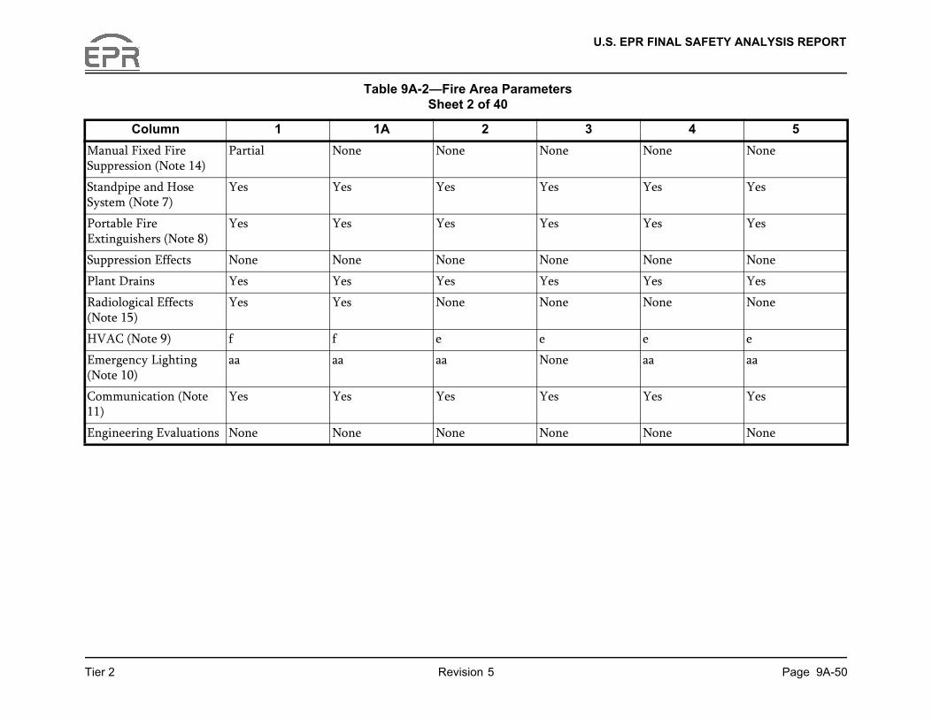
U.S. EPR FINAL SAFETY ANALYSIS REPORT
Page 9A-50
4 5
one None
es Yes
es Yes
one None
es Yes
one None
e
a aa
es Yes
one None
Tier 2 Revision 5
Column 1 1A 2 3
Manual Fixed Fire Suppression (Note 14)
Partial None None None N
Standpipe and Hose System (Note 7)
Yes Yes Yes Yes Y
Portable Fire Extinguishers (Note 8)
Yes Yes Yes Yes Y
Suppression Effects None None None None N
Plant Drains Yes Yes Yes Yes Y
Radiological Effects (Note 15)
Yes Yes None None N
HVAC (Note 9) f f e e e
Emergency Lighting (Note 10)
aa aa aa None a
Communication (Note 11)
Yes Yes Yes Yes Y
Engineering Evaluations None None None None N
Table 9A-2—Fire Area Parameters Sheet 2 of 40
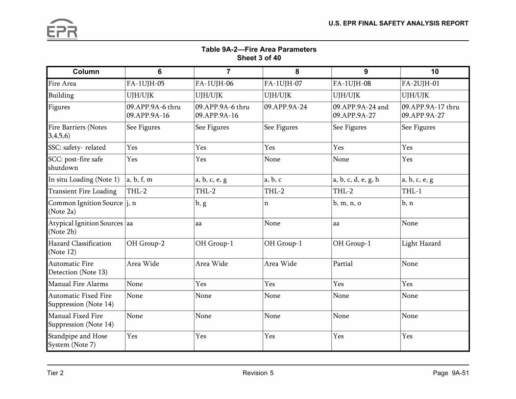
U.S. EPR FINAL SAFETY ANALYSIS REPORT
Page 9A-51
9 10
-08 FA-2UJH-01
UJH/UJK
A-24 and A-27
09.APP.9A-17 thru 09.APP.9A-27
res See Figures
Yes
Yes
e, g, h a, b, c, e, g
THL-1
b, n
None
p-1 Light Hazard
None
Yes
None
None
Yes
Tier 2 Revision 5
Column 6 7 8
Fire Area FA-1UJH-05 FA-1UJH-06 FA-1UJH-07 FA-1UJH
Building UJH/UJK UJH/UJK UJH/UJK UJH/UJK
Figures 09.APP.9A-6 thru 09.APP.9A-16
09.APP.9A-6 thru 09.APP.9A-16
09.APP.9A-24 09.APP.909.APP.9
Fire Barriers (Notes 3,4,5,6)
See Figures See Figures See Figures See Figu
SSC: safety- related Yes Yes Yes Yes
SCC: post-fire safe shutdown
Yes Yes None None
In situ Loading (Note 1) a, b, f, m a, b, c, e, g a, b, c a, b, c, d,
Transient Fire Loading THL-2 THL-2 THL-2 THL-2
Common Ignition Source (Note 2a)
j, n b, g n b, m, n, o
Atypical Ignition Sources (Note 2b)
aa aa None aa
Hazard Classification (Note 12)
OH Group-2 OH Group-1 OH Group-1 OH Grou
Automatic Fire Detection (Note 13)
Area Wide Area Wide Area Wide Partial
Manual Fire Alarms None Yes Yes Yes
Automatic Fixed Fire Suppression (Note 14)
None None None None
Manual Fixed Fire Suppression (Note 14)
None None None None
Standpipe and Hose System (Note 7)
Yes Yes Yes Yes
Table 9A-2—Fire Area Parameters Sheet 3 of 40

U.S. EPR FINAL SAFETY ANALYSIS REPORT
Page 9A-52
9 10
Yes
None
Yes
None
e, i
aa
Yes
None
Tier 2 Revision 5
Column 6 7 8
Portable Fire Extinguishers (Note 8)
Yes Yes Yes Yes
Suppression Effects None None None None
Plant Drains Yes Yes Yes Yes
Radiological Effects (Note 15)
None None None None
HVAC (Note 9) e e e e
Emergency Lighting (Note 10)
aa aa aa aa
Communication (Note 11)
Yes Yes Yes Yes
Engineering Evaluations None None None None
Table 9A-2—Fire Area Parameters Sheet 4 of 40
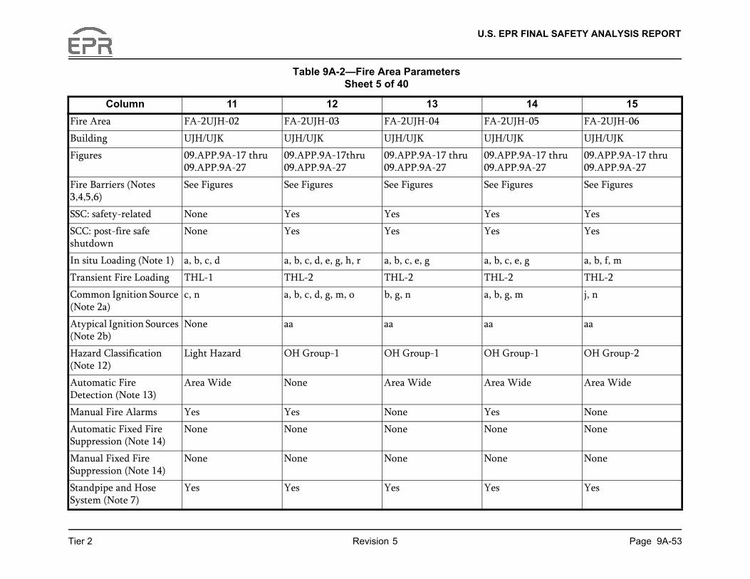
U.S. EPR FINAL SAFETY ANALYSIS REPORT
Page 9A-53
14 15
-05 FA-2UJH-06
UJH/UJK
A-17 thru A-27
09.APP.9A-17 thru 09.APP.9A-27
res See Figures
Yes
Yes
g a, b, f, m
THL-2
j, n
aa
p-1 OH Group-2
de Area Wide
None
None
None
Yes
Tier 2 Revision 5
Column 11 12 13
Fire Area FA-2UJH-02 FA-2UJH-03 FA-2UJH-04 FA-2UJH
Building UJH/UJK UJH/UJK UJH/UJK UJH/UJK
Figures 09.APP.9A-17 thru 09.APP.9A-27
09.APP.9A-17thru 09.APP.9A-27
09.APP.9A-17 thru 09.APP.9A-27
09.APP.909.APP.9
Fire Barriers (Notes 3,4,5,6)
See Figures See Figures See Figures See Figu
SSC: safety-related None Yes Yes Yes
SCC: post-fire safe shutdown
None Yes Yes Yes
In situ Loading (Note 1) a, b, c, d a, b, c, d, e, g, h, r a, b, c, e, g a, b, c, e,
Transient Fire Loading THL-1 THL-2 THL-2 THL-2
Common Ignition Source (Note 2a)
c, n a, b, c, d, g, m, o b, g, n a, b, g, m
Atypical Ignition Sources (Note 2b)
None aa aa aa
Hazard Classification (Note 12)
Light Hazard OH Group-1 OH Group-1 OH Grou
Automatic Fire Detection (Note 13)
Area Wide None Area Wide Area Wi
Manual Fire Alarms Yes Yes None Yes
Automatic Fixed Fire Suppression (Note 14)
None None None None
Manual Fixed Fire Suppression (Note 14)
None None None None
Standpipe and Hose System (Note 7)
Yes Yes Yes Yes
Table 9A-2—Fire Area Parameters Sheet 5 of 40

U.S. EPR FINAL SAFETY ANALYSIS REPORT
Page 9A-54
14 15
Yes
None
Yes
None
e
aa
Yes
None
Tier 2 Revision 5
Column 11 12 13
Portable Fire Extinguishers (Note 8)
Yes Yes Yes Yes
Suppression Effects None None None None
Plant Drains Yes Yes Yes Yes
Radiological Effects (Note 15)
None None None None
HVAC (Note 9) e e e e
Emergency Lighting (Note 10)
None aa aa aa
Communication (Note 11)
Yes Yes Yes Yes
Engineering Evaluations None None None None
Table 9A-2—Fire Area Parameters Sheet 6 of 40

U.S. EPR FINAL SAFETY ANALYSIS REPORT
Page 9A-55
19 20
-10 FA-3UJH-01
UJH/UJK
A-12 thru A-14
09.APP.9A-17 thru 09.APP.9A-27
res See Figures
Yes
Yes
a, b, c, g
THL-1
b, n
aa
zard Light Hazard
None
Yes
None
None
Tier 2 Revision 5
Column 16 17 18
Fire Area FA-2UJH-07 FA-2UJH-08 FA-2UJH-09 FA-2UJH
Building UJH/UJK UJH/UJK UJH/UJK UJH/UJK
Figures 09.APP.9A-17 thru 09.APP.9A-27
09.APP.9A-17 thru 09.APP.9A-27
09.APP.9A-17 thru 09.APP.9A-27
09.APP.909.APP.9
Fire Barriers (Notes 3,4,5,6)
See Figures See Figures See Figures See Figu
SSC: important to safety Yes Yes Yes Yes
SCC: post-fire safe shutdown
Yes Yes Yes Yes
In situ Loading (Note 1) a, b, c, e, g, m, n, o, p, q, r, s
a, b, c, g, s a a, b, d
Transient Fire Loading THL-2 THL-2 THL-1 THL-1
Common Ignition Source (Note 2a)
b, m, n m, n n n
Atypical Ignition Sources (Note 2b)
None None None None
Hazard Classification (Note 12)
OH Group-1 OH Group-1 Light Hazard Light Ha
Automatic Fire Detection (Note 13)
Area Wide Area Wide None Partial
Manual Fire Alarms None Yes None None
Automatic Fixed Fire Suppression (Note 14)
None None None None
Manual Fixed Fire Suppression (Note 14)
Partial None None None
Table 9A-2—Fire Area Parameters Sheet 7 of 40

U.S. EPR FINAL SAFETY ANALYSIS REPORT
Page 9A-56
19 20
Yes
Yes
None
Yes
None
e
aa
Yes
None
Tier 2 Revision 5
Column 16 17 18
Standpipe and Hose System (Note 7)
Yes Yes Yes Yes
Portable Fire Extinguishers (Note 8)
Yes Yes Yes Yes
Suppression Effects None None None None
Plant Drains Yes Yes Yes Yes
Radiological Effects (Note 15)
None None None None
HVAC (Note 9) e e e e
Emergency Lighting (Note 10)
cc, dd aa aa aa
Communication (Note 11)
Yes Yes Yes Yes
Engineering Evaluations None None None None
Table 9A-2—Fire Area Parameters Sheet 8 of 40

U.S. EPR FINAL SAFETY ANALYSIS REPORT
Page 9A-57
24 25
-05 FA-3UJH-06
UJH/UJK
A-17 thru A-27
09.APP.9A-17 thru 09.APP.9A-27
res See Figures
Yes
Yes
g a, b, c, g, f, m
THL-2
j, n
aa
p-1 OH Group-2
de Area Wide
None
None
None
Yes
Tier 2 Revision 5
Column 21 22 23
Fire Area FA-3UJH-02 FA-3UJH-03 FA-3UJH-04 FA-3UJH
Building UJH/UJK UJH/UJK UJH/UJK UJH/UJK
Figures 09.APP.9A-17 thru 09.APP.9A-27
09.APP.9A-17 thru 09.APP.9A-27
09.APP.9A-17 thru 09.APP.9A-27
09.APP.909.APP.9
Fire Barriers (Notes 3,4,5,6)
See Figures See Figures See Figures See Figu
SSC: safety-related None Yes Yes Yes
SCC: post-fire safe shutdown
None Yes Yes Yes
In situ Loading (Note 1) a, b, c, d a, b, c, d, e, g, h, r a, b, c, e, g a, b, c, e,
Transient Fire Loading THL-1 THL-2 THL-2 THL-2
Common Ignition Source (Note 2a)
c, n b, c, d, m, n, o b, g, n a, b, g, m
Atypical Ignition Sources (Note 2b)
None None aa aa
Hazard Classification (Note 12)
Light Hazard OH Group-1 OH Group-1 OH Grou
Automatic Fire Detection (Note 13)
Area Wide None Area Wide Area Wi
Manual Fire Alarms Yes Yes Yes Yes
Automatic Fixed Fire Suppression (Note 14)
None None None None
Manual Fixed Fire Suppression (Note 14)
None None None None
Standpipe and Hose System (Note 7)
Yes Yes Yes Yes
Table 9A-2—Fire Area Parameters Sheet 9 of 40

U.S. EPR FINAL SAFETY ANALYSIS REPORT
Page 9A-58
24 25
Yes
None
Yes
None
e
aa
Yes
None
Tier 2 Revision 5
Column 21 22 23
Portable Fire Extinguishers (Note 8)
Yes Yes Yes Yes
Suppression Effects None None None None
Plant Drains Yes Yes Yes Yes
Radiological Effects (Note 15)
None None None None
HVAC (Note 9) e e e e
Emergency Lighting (Note 10)
None aa aa aa
Communication (Note 11)
Yes Yes Yes Yes
Engineering Evaluations None None None None
Table 9A-2—Fire Area Parameters Sheet 10 of 40
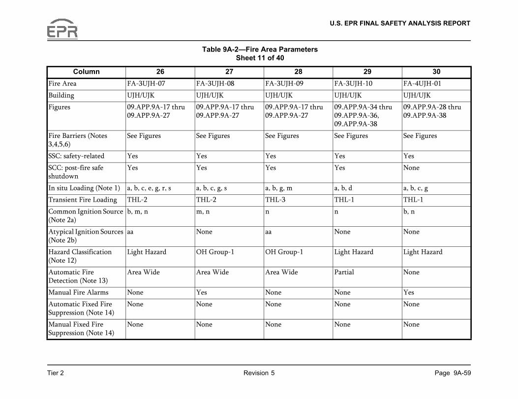
U.S. EPR FINAL SAFETY ANALYSIS REPORT
Page 9A-59
29 30
-10 FA-4UJH-01
UJH/UJK
A-34 thru A-36, A-38
09.APP.9A-28 thru 09.APP.9A-38
res See Figures
Yes
None
a, b, c, g
THL-1
b, n
None
zard Light Hazard
None
Yes
None
None
Tier 2 Revision 5
Column 26 27 28
Fire Area FA-3UJH-07 FA-3UJH-08 FA-3UJH-09 FA-3UJH
Building UJH/UJK UJH/UJK UJH/UJK UJH/UJK
Figures 09.APP.9A-17 thru 09.APP.9A-27
09.APP.9A-17 thru 09.APP.9A-27
09.APP.9A-17 thru 09.APP.9A-27
09.APP.909.APP.909.APP.9
Fire Barriers (Notes 3,4,5,6)
See Figures See Figures See Figures See Figu
SSC: safety-related Yes Yes Yes Yes
SCC: post-fire safe shutdown
Yes Yes Yes Yes
In situ Loading (Note 1) a, b, c, e, g, r, s a, b, c, g, s a, b, g, m a, b, d
Transient Fire Loading THL-2 THL-2 THL-3 THL-1
Common Ignition Source (Note 2a)
b, m, n m, n n n
Atypical Ignition Sources (Note 2b)
aa None aa None
Hazard Classification (Note 12)
Light Hazard OH Group-1 OH Group-1 Light Ha
Automatic Fire Detection (Note 13)
Area Wide Area Wide Area Wide Partial
Manual Fire Alarms None Yes None None
Automatic Fixed Fire Suppression (Note 14)
None None None None
Manual Fixed Fire Suppression (Note 14)
None None None None
Table 9A-2—Fire Area Parameters Sheet 11 of 40

U.S. EPR FINAL SAFETY ANALYSIS REPORT
Page 9A-60
29 30
Yes
Yes
None
Yes
None
e
aa
Yes
None
Tier 2 Revision 5
Column 26 27 28
Standpipe and Hose System (Note 7)
Yes Yes Yes Yes
Portable Fire Extinguishers (Note 8)
Yes Yes Yes Yes
Suppression Effects None None None None
Plant Drains Yes Yes Yes Yes
Radiological Effects (Note 15)
None None None None
HVAC (Note 9) e e e e
Emergency Lighting (Note 10)
cc, dd aa aa aa
Communication (Note 11)
Yes Yes Yes Yes
Engineering Evaluations None None None None
Table 9A-2—Fire Area Parameters Sheet 12 of 40

U.S. EPR FINAL SAFETY ANALYSIS REPORT
Page 9A-61
34 35
-05 FA-4UJH-06
UJH/UJK
A-28 thru A-38
09.APP.9A-28thru 09.APP.9A-38
res See Figures
Yes
Yes
m a, b, c, e, g
THL-2
a, b, g
aa
p-2 OH Group-1
de Area Wide
Yes
None
None
Tier 2 Revision 5
Column 31 32 33
Fire Area FA-4UJH-02 FA-4UJH-03 FA-4UJH-04 FA-4UJH
Building UJH/UJK UJH/UJK UJH/UJK UJH/UJK
Figures 09.APP.9A-28thru 09.APP.9A-38
09.APP.9A-28 thru 09.APP.9A-38
09.APP.9A-22, 09.APP.9A-27, and 09.APP.9A-28 thru 09.APP.9A-38
09.APP.909.APP.9
Fire Barriers (Notes 3,4,5,6)
See Figures See Figures See Figures See Figu
SSC: safety-related None Yes Yes Yes
SCC: post-fire safe shutdown
None Yes Yes Yes
In situ Loading (Note 1) a, b, c, d a, b, c, d, e, f, g, h, j, t a, b, c, e, g a, b, f, g,
Transient Fire Loading THL-1 THL-2 THL-2 THL-2
Common Ignition Source (Note 2a)
c, n a, b, c, d, o b, n j, n
Atypical Ignition Sources (Note 2b)
None aa aa aa
Hazard Classification (Note 12)
Light Hazard OH Group-1 OH Group-1 OH Grou
Automatic Fire Detection (Note 13)
Area Wide None Partial Area Wi
Manual Fire Alarms Yes Yes Yes None
Automatic Fixed Fire Suppression (Note 14)
None None None None
Manual Fixed Fire Suppression (Note 14)
None None None None
Table 9A-2—Fire Area Parameters Sheet 13 of 40

U.S. EPR FINAL SAFETY ANALYSIS REPORT
Page 9A-62
34 35
Yes
Yes
None
Yes
None
e
aa
Yes
None
Tier 2 Revision 5
Column 31 32 33
Standpipe and Hose System (Note 7)
Yes Yes Yes Yes
Portable Fire Extinguishers (Note 8)
Yes Yes Yes Yes
Suppression Effects None None None None
Plant Drains Yes Yes Yes Yes
Radiological Effects (Note 15)
None None None None
HVAC (Note 9) e e e e
Emergency Lighting (Note 10)
None aa aa aa
Communication (Note 11)
Yes Yes Yes Yes
Engineering Evaluations None None None None
Table 9A-2—Fire Area Parameters Sheet 14 of 40
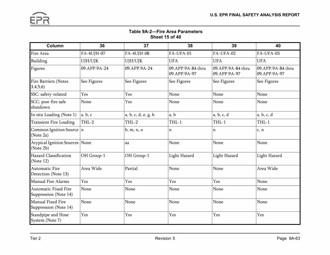
U.S. EPR FINAL SAFETY ANALYSIS REPORT
Page 9A-63
39 40
-02 FA-UFA-03
UFA
A-84 thru A-97
09.APP.9A-84 thru 09.APP.9A-97
res See Figures
None
None
a, b, c, d
THL-1
c, n
None
zard Light Hazard
Area Wide
None
None
None
Yes
Tier 2 Revision 5
Column 36 37 38
Fire Area FA-4UJH-07 FA-4UJH-08 FA-UFA-01 FA-UFA
Building UJH/UJK UJH/UJK UFA UFA
Figures 09.APP.9A-24 09.APP.9A-24 09.APP.9A-84 thru 09.APP.9A-97
09.APP.909.APP.9
Fire Barriers (Notes 3,4,5,6)
See Figures See Figures See Figures See Figu
SSC: safety-related Yes Yes None None
SCC: post-fire safe shutdown
None Yes None None
In situ Loading (Note 1) a, b, c a, b, c, d, e, g, h a, b a, b, c, d
Transient Fire Loading THL-2 THL-2 THL-1 THL-1
Common Ignition Source (Note 2a)
n b, m, n, o n n
Atypical Ignition Sources (Note 2b)
None aa None None
Hazard Classification (Note 12)
OH Group-1 OH Group-1 Light Hazard Light Ha
Automatic Fire Detection (Note 13)
Area Wide Partial None None
Manual Fire Alarms Yes Yes Yes Yes
Automatic Fixed Fire Suppression (Note 14)
None None None None
Manual Fixed Fire Suppression (Note 14)
None None None None
Standpipe and Hose System (Note 7)
Yes Yes Yes Yes
Table 9A-2—Fire Area Parameters Sheet 15 of 40

U.S. EPR FINAL SAFETY ANALYSIS REPORT
Page 9A-64
39 40
Yes
None
Yes
Yes
b
None
Yes
None
Tier 2 Revision 5
Column 36 37 38
Portable Fire Extinguishers (Note 8)
Yes Yes Yes Yes
Suppression Effects None None None None
Plant Drains Yes Yes Yes Yes
Radiological Effects (Note 15)
None None Yes Yes
HVAC (Note 9) e e b b
Emergency Lighting (Note 10)
aa aa aa aa
Communication (Note 11)
Yes Yes Yes Yes
Engineering Evaluations None None None None
Table 9A-2—Fire Area Parameters Sheet 16 of 40

U.S. EPR FINAL SAFETY ANALYSIS REPORT
Page 9A-65
44 45
-07 FA-UFA-08
UFA
A-84 thru A-97
09.APP.9A-84 thru 09.APP.9A-97
res See Figures
None
None
e, g, o, p, q, r a
THL-1
m, o n
None
p-1 Light Hazard
de None
None
None
None
Yes
Tier 2 Revision 5
Column 41 42 43
Fire Area FA-UFA-04 FA-UFA-05 FA-UFA-06 FA-UFA
Building UFA UFA UFA UFA
Figures 09.APP.9A-84 thru 09.APP.9A-97
09.APP.9A-84 thru 09.APP.9A-97
09.APP.9A-84 thru 09.APP.9A-97
09.APP.909.APP.9
Fire Barriers (Notes 3,4,5,6)
See Figures See Figures See Figures See Figu
SSC: safety-related None Yes Yes Yes
SCC: post-fire safe shutdown
None Yes None Yes
In situ Loading (Note 1) a, b, c, d a, b, c, d, e, g, o, p, q, r a, g a, b, c, d,
Transient Fire Loading THL-1 THL-2 THL-1 THL-2
Common Ignition Source (Note 2a)
c, n a, b, c, d, m, o n a, b, c, d,
Atypical Ignition Sources (Note 2b)
None None aa aa
Hazard Classification (Note 12)
Light Hazard OH Group-1 OH Group-1 OH Grou
Automatic Fire Detection (Note 13)
Area Wide None Area Wide Area Wi
Manual Fire Alarms None Yes None Yes
Automatic Fixed Fire Suppression (Note 14)
None None None None
Manual Fixed Fire Suppression (Note 14)
None None None None
Standpipe and Hose System (Note 7)
Yes Yes Yes Yes
Table 9A-2—Fire Area Parameters Sheet 17 of 40

U.S. EPR FINAL SAFETY ANALYSIS REPORT
Page 9A-66
44 45
Yes
None
Yes
None
b
None
Yes
None
Tier 2 Revision 5
Column 41 42 43
Portable Fire Extinguishers (Note 8)
Yes Yes Yes Yes
Suppression Effects None None None None
Plant Drains Yes Yes Yes Yes
Radiological Effects (Note 15)
Yes Yes None Yes
HVAC (Note 9) b b b b
Emergency Lighting (Note 10)
None aa None aa
Communication (Note 11)
Yes Yes Yes Yes
Engineering Evaluations None None None None
Table 9A-2—Fire Area Parameters Sheet 18 of 40

U.S. EPR FINAL SAFETY ANALYSIS REPORT
Page 9A-67
49 50
-12 FA-UFA-13
UFA
A-84 thru A-97
09.APP.9A-84 thru 09.APP.9A-97
res See Figures
Yes
None
a, b, c, h
THL-2
a, c, m
None
p-1 OH Group-1
Area Wide
None
None
None
Yes
Tier 2 Revision 5
Column 46 47 48
Fire Area FA-UFA-09 FA-UFA-10 FA-UFA-11 FA-UFA
Building UFA UFA UFA UFA
Figures 09.APP.9A-84 thru 09.APP.9A-97
09.APP.9A-84 thru 09.APP.9A-97
09.APP.9A-84 thru 09.APP.9A-97
09.APP.909.APP.9
Fire Barriers (Notes 3,4,5,6)
See Figures See Figures See Figures See Figu
SSC: safety-related Yes None None Yes
SCC: post-fire safe shutdown
None None None None
In situ Loading (Note 1) a, g a a, b, c, d, p, q, r a, b, c, h
Transient Fire Loading THL-1 THL-1 THL-2 THL-2
Common Ignition Source (Note 2a)
n n c, n, c, m, n
Atypical Ignition Sources (Note 2b)
aa None None None
Hazard Classification (Note 12)
OH Group-1 Light Hazard OH Group-1 OH Grou
Automatic Fire Detection (Note 13)
Area Wide Area Wide None None
Manual Fire Alarms None None Yes None
Automatic Fixed Fire Suppression (Note 14)
None None None None
Manual Fixed Fire Suppression (Note 14)
None None None None
Standpipe and Hose System (Note 7)
Yes Yes Yes Yes
Table 9A-2—Fire Area Parameters Sheet 19 of 40

U.S. EPR FINAL SAFETY ANALYSIS REPORT
Page 9A-68
49 50
Yes
None
Yes
Yes
b
aa
Yes
None
Tier 2 Revision 5
Column 46 47 48
Portable Fire Extinguishers (Note 8)
Yes Yes Yes Yes
Suppression Effects None None None None
Plant Drains Yes Yes Yes Yes
Radiological Effects (Note 15)
None None None Yes
HVAC (Note 9) b b b b
Emergency Lighting (Note 10)
None None aa aa
Communication (Note 11)
Yes Yes Yes Yes
Engineering Evaluations None None None None
Table 9A-2—Fire Area Parameters Sheet 20 of 40
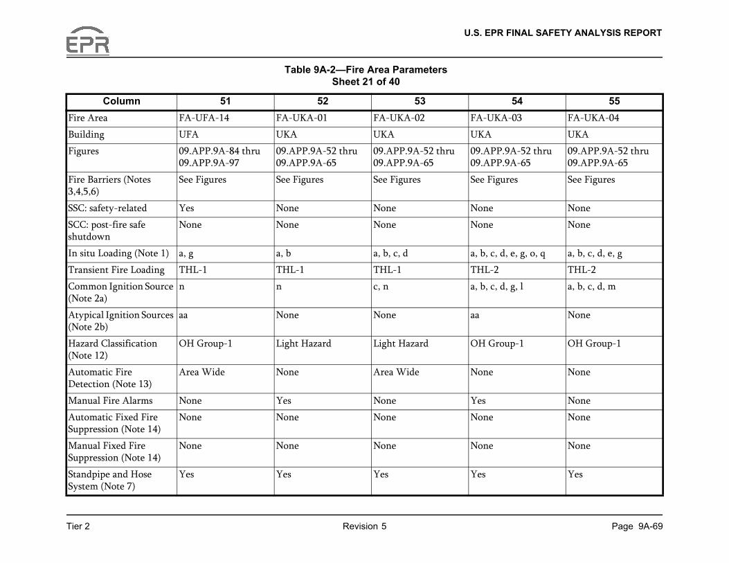
U.S. EPR FINAL SAFETY ANALYSIS REPORT
Page 9A-69
54 55
-03 FA-UKA-04
UKA
A-52 thru A-65
09.APP.9A-52 thru 09.APP.9A-65
res See Figures
None
None
e, g, o, q a, b, c, d, e, g
THL-2
g, l a, b, c, d, m
None
p-1 OH Group-1
None
None
None
None
Yes
Tier 2 Revision 5
Column 51 52 53
Fire Area FA-UFA-14 FA-UKA-01 FA-UKA-02 FA-UKA
Building UFA UKA UKA UKA
Figures 09.APP.9A-84 thru 09.APP.9A-97
09.APP.9A-52 thru 09.APP.9A-65
09.APP.9A-52 thru 09.APP.9A-65
09.APP.909.APP.9
Fire Barriers (Notes 3,4,5,6)
See Figures See Figures See Figures See Figu
SSC: safety-related Yes None None None
SCC: post-fire safe shutdown
None None None None
In situ Loading (Note 1) a, g a, b a, b, c, d a, b, c, d,
Transient Fire Loading THL-1 THL-1 THL-1 THL-2
Common Ignition Source (Note 2a)
n n c, n a, b, c, d,
Atypical Ignition Sources (Note 2b)
aa None None aa
Hazard Classification (Note 12)
OH Group-1 Light Hazard Light Hazard OH Grou
Automatic Fire Detection (Note 13)
Area Wide None Area Wide None
Manual Fire Alarms None Yes None Yes
Automatic Fixed Fire Suppression (Note 14)
None None None None
Manual Fixed Fire Suppression (Note 14)
None None None None
Standpipe and Hose System (Note 7)
Yes Yes Yes Yes
Table 9A-2—Fire Area Parameters Sheet 21 of 40

U.S. EPR FINAL SAFETY ANALYSIS REPORT
Page 9A-70
54 55
Yes
None
Yes
None
c
aa
Yes
None
Tier 2 Revision 5
Column 51 52 53
Portable Fire Extinguishers (Note 8)
Yes Yes Yes Yes
Suppression Effects None None None None
Plant Drains Yes Yes Yes Yes
Radiological Effect (Note 15)
None Yes None Yes
HVAC (Note 9) b c c c
Emergency Lighting (Note 10)
aa aa None aa
Communication (Note 11)
Yes Yes Yes Yes
Engineering Evaluations None None None None
Table 9A-2—Fire Area Parameters Sheet 22 of 40

U.S. EPR FINAL SAFETY ANALYSIS REPORT
Page 9A-71
59 60
-08 FA-UKA-09
UKA
A-52 thru A-65
09.APP.9A-52 thru 09.APP.9A-65
res See Figures
None
None
a, b
THL-1
n
None
p-1 Light Hazard
de None
None
None
None
Tier 2 Revision 5
Column 56 57 58
Fire Area FA-UKA-05 FA-UKA-06 FA-UKA-07 FA-UKA
Building UKA UKA UKA UKA
Figures 09.APP.9A-52 thru 09.APP.9A-65, 09.APP.9A-93 thru 09.APP.9A-94
09.APP.9A-52 thru 09.APP.9A-65
09.APP.9A-52 thru 09.APP.9A-65
09.APP.909.APP.9
Fire Barriers (Notes 3,4,5,6)
See Figures See Figures See Figures See Figu
SSC: safety-related None Yes Yes Yes
SCC: post-fire safe shutdown
None None None None
In situ Loading (Note 1) a, b, c, d, e, g, h a, b, g a, b, g b, g
Transient Fire Loading THL-2 THL-1 THL-1 THL-1
Common Ignition Source (Note 2a)
b, c, d, m, n a a a
Atypical Ignition Sources (Note 2b)
None aa aa aa
Hazard Classification (Note 12)
OH Group-1 OH Group-1 OH Group-1 OH Grou
Automatic Fire Detection (Note 13)
None Area Wide Area Wide Area Wi
Manual Fire Alarms Yes None None None
Automatic Fixed Fire Suppression (Note 14)
None None None None
Manual Fixed Fire Suppression (Note 14)
None None None None
Table 9A-2—Fire Area Parameters Sheet 23 of 40
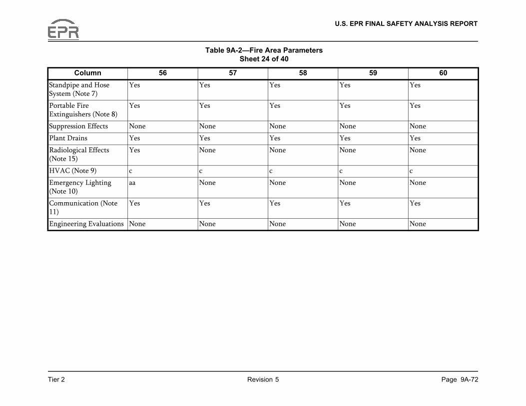
U.S. EPR FINAL SAFETY ANALYSIS REPORT
Page 9A-72
59 60
Yes
Yes
None
Yes
None
c
None
Yes
None
Tier 2 Revision 5
Column 56 57 58
Standpipe and Hose System (Note 7)
Yes Yes Yes Yes
Portable Fire Extinguishers (Note 8)
Yes Yes Yes Yes
Suppression Effects None None None None
Plant Drains Yes Yes Yes Yes
Radiological Effects (Note 15)
Yes None None None
HVAC (Note 9) c c c c
Emergency Lighting (Note 10)
aa None None None
Communication (Note 11)
Yes Yes Yes Yes
Engineering Evaluations None None None None
Table 9A-2—Fire Area Parameters Sheet 24 of 40
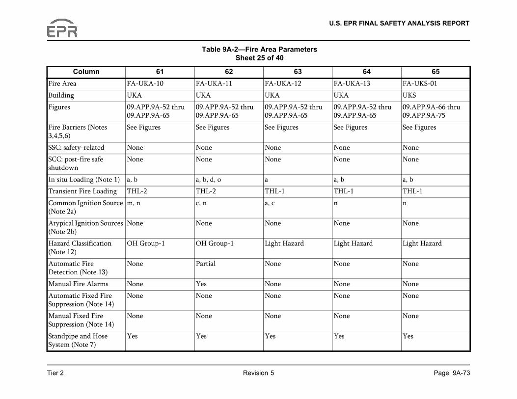
U.S. EPR FINAL SAFETY ANALYSIS REPORT
Page 9A-73
64 65
-13 FA-UKS-01
UKS
A-52 thru A-65
09.APP.9A-66 thru 09.APP.9A-75
res See Figures
None
None
a, b
THL-1
n
None
zard Light Hazard
None
None
None
None
Yes
Tier 2 Revision 5
Column 61 62 63
Fire Area FA-UKA-10 FA-UKA-11 FA-UKA-12 FA-UKA
Building UKA UKA UKA UKA
Figures 09.APP.9A-52 thru 09.APP.9A-65
09.APP.9A-52 thru 09.APP.9A-65
09.APP.9A-52 thru 09.APP.9A-65
09.APP.909.APP.9
Fire Barriers (Notes 3,4,5,6)
See Figures See Figures See Figures See Figu
SSC: safety-related None None None None
SCC: post-fire safe shutdown
None None None None
In situ Loading (Note 1) a, b a, b, d, o a a, b
Transient Fire Loading THL-2 THL-2 THL-1 THL-1
Common Ignition Source (Note 2a)
m, n c, n a, c n
Atypical Ignition Sources (Note 2b)
None None None None
Hazard Classification (Note 12)
OH Group-1 OH Group-1 Light Hazard Light Ha
Automatic Fire Detection (Note 13)
None Partial None None
Manual Fire Alarms None Yes None None
Automatic Fixed Fire Suppression (Note 14)
None None None None
Manual Fixed Fire Suppression (Note 14)
None None None None
Standpipe and Hose System (Note 7)
Yes Yes Yes Yes
Table 9A-2—Fire Area Parameters Sheet 25 of 40

U.S. EPR FINAL SAFETY ANALYSIS REPORT
Page 9A-74
64 65
Yes
None
Yes
None
c
aa
Yes
None
Tier 2 Revision 5
Column 61 62 63
Portable Fire Extinguishers (Note 8)
Yes Yes Yes Yes
Suppression Effects None None None None
Plant Drains Yes Yes Yes Yes
Radiological Effects (Note 15)
Yes Yes None None
HVAC (Note 9) c c c c
Emergency Lighting (Note 10)
aa aa aa None
Communication (Note 11)
Yes Yes Yes Yes
Engineering Evaluations None None None None
Table 9A-2—Fire Area Parameters Sheet 26 of 40

U.S. EPR FINAL SAFETY ANALYSIS REPORT
Page 9A-75
69 70
-05 FA-UKS-06
UKS
A-66 thru A-75
09.APP.9A-66 thru 09.APP.9A-75
res See Figures
None
None
a, b, g
THL-1
b
aa
p-1 OH Group-1
de Area Wide
None
None
None
Tier 2 Revision 5
Column 66 67 68
Fire Area FA-UKS-02 FA-UKS-03 FA-UKS-04 FA-UKS
Building UKS UKS UKS UKS
Figures 09.APP.9A-66 thru 09.APP.9A-75
09.APP.9A-66 thru 09.APP.9A-75
09.APP.9A-66 thru 09.APP.9A-75
09.APP.909.APP.9
Fire Barriers (Notes 3,4,5,6)
See Figures See Figures See Figures See Figu
SSC: safety-related None None None None
SCC: post-fire safe shutdown
None None None None
In situ Loading (Note 1) a, b, c, d a, b, c, d, e, f, g, o, p, q, s
a, b, c, d, e, g, h, o a, b, e, g
Transient Fire Loading THL-1 THL-3 THL-2 THL-2
Common Ignition Source (Note 2a)
c, n a, b, c, d, l a, b, c, d, m a, b
Atypical Ignition Sources (Note 2b)
None aa, ee None aa
Hazard Classification (Note 12)
Light Hazard OH Group-2 OH Group-1 OH Grou
Automatic Fire Detection (Note 13)
Area Wide None None Area Wi
Manual Fire Alarms None None None None
Automatic Fixed Fire Suppression (Note 14)
None None None None
Manual Fixed Fire Suppression (Note 14)
None None None None
Table 9A-2—Fire Area Parameters Sheet 27 of 40

U.S. EPR FINAL SAFETY ANALYSIS REPORT
Page 9A-76
69 70
Yes
Yes
None
Yes
None
c
None
Yes
None
Tier 2 Revision 5
Column 66 67 68
Standpipe and Hose System (Note 7)
Yes Yes Yes Yes
Portable Fire Extinguishers (Note 8)
Yes Yes Yes Yes
Suppression Effects None None None None
Plant Drains Yes Yes Yes Yes
Radiological Effects (Note 15)
None Yes None None
HVAC (Note 9) c c c c
Emergency Lighting (Note 10)
None aa aa aa
Communication (Note 11)
Yes Yes Yes Yes
Engineering Evaluations None None None None
Table 9A-2—Fire Area Parameters Sheet 28 of 40

U.S. EPR FINAL SAFETY ANALYSIS REPORT
Page 9A-77
74 75
-02 FA-1UBP-03
UBP
A-1 thru A-5
09.APP.9A-1 thru 09.APP.9A-5
res See Figures
Yes
Yes
g a, b, c, d, e, g, n
THL-3
a, b, c, i, m
aa, ee
p-1 EH Group-2
de Area Wide
Yes
Area Wide
None
Yes
Tier 2 Revision 5
Column 71 72 73
Fire Area FA-UKS-07 FA-UKS-08 FA-1UBP-01 FA-1UBP
Building UKS UKS UBP UBP
Figures 09.APP.9A-66 thru 09.APP.9A-75
09.APP.9A-66 thru 09.APP.9A-75
09.APP.9A-1 thru 09.APP.9A-5
09.APP.909.APP.9
Fire Barriers (Notes 3,4,5,6)
See Figures See Figures See Figures See Figu
SSC: safety-related None None Yes Yes
SCC: post-fire safe shutdown
None None Yes Yes
In situ Loading (Note 1) a, b, c, d, r, s a, b, h n a, b, c, e,
Transient Fire Loading THL-2 THL-1 THL-1 THL-1
Common Ignition Source (Note 2a)
c, n, o m, n m, n b, n
Atypical Ignition Sources (Note 2b)
None None ee aa
Hazard Classification (Note 12)
OH Group-1 OH Group-1 EH Group-2 OH Grou
Automatic Fire Detection (Note 13)
None None Area Wide Area Wi
Manual Fire Alarms None None None Yes
Automatic Fixed Fire Suppression (Note 14)
None None Area Wide None
Manual Fixed Fire Suppression (Note 14)
None None None None
Standpipe and Hose System (Note 7)
Yes Yes Yes Yes
Table 9A-2—Fire Area Parameters Sheet 29 of 40
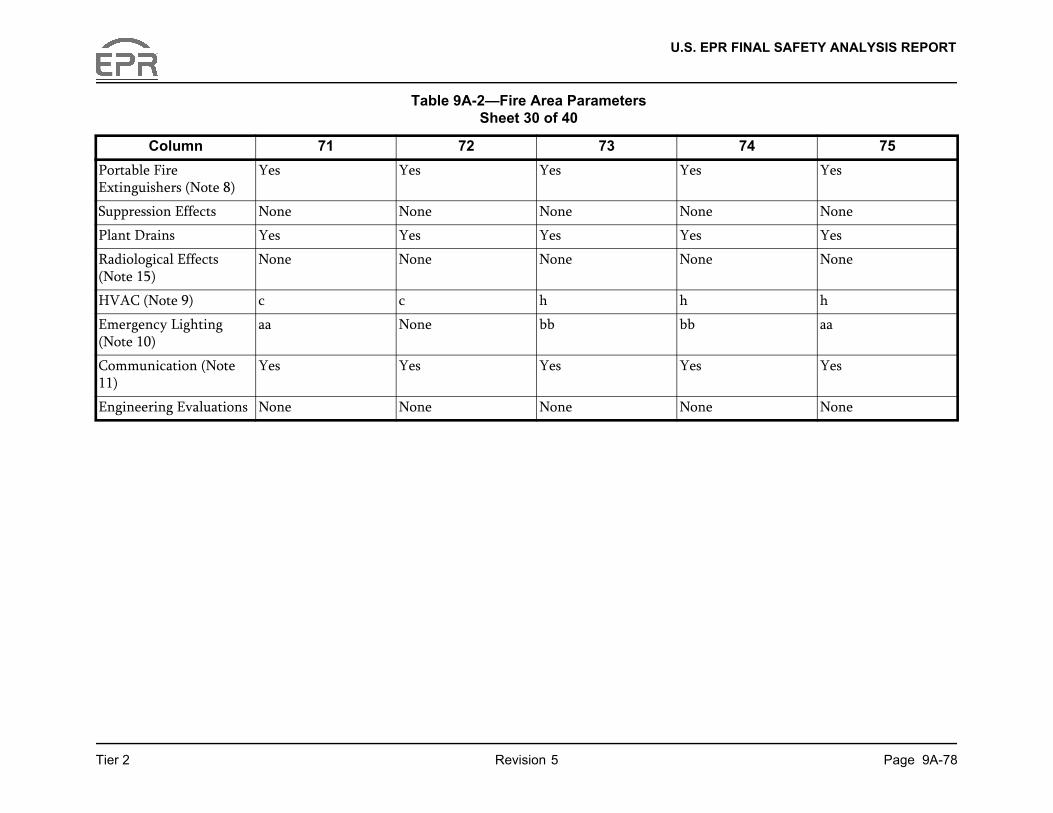
U.S. EPR FINAL SAFETY ANALYSIS REPORT
Page 9A-78
74 75
Yes
None
Yes
None
h
aa
Yes
None
Tier 2 Revision 5
Column 71 72 73
Portable Fire Extinguishers (Note 8)
Yes Yes Yes Yes
Suppression Effects None None None None
Plant Drains Yes Yes Yes Yes
Radiological Effects (Note 15)
None None None None
HVAC (Note 9) c c h h
Emergency Lighting (Note 10)
aa None bb bb
Communication (Note 11)
Yes Yes Yes Yes
Engineering Evaluations None None None None
Table 9A-2—Fire Area Parameters Sheet 30 of 40
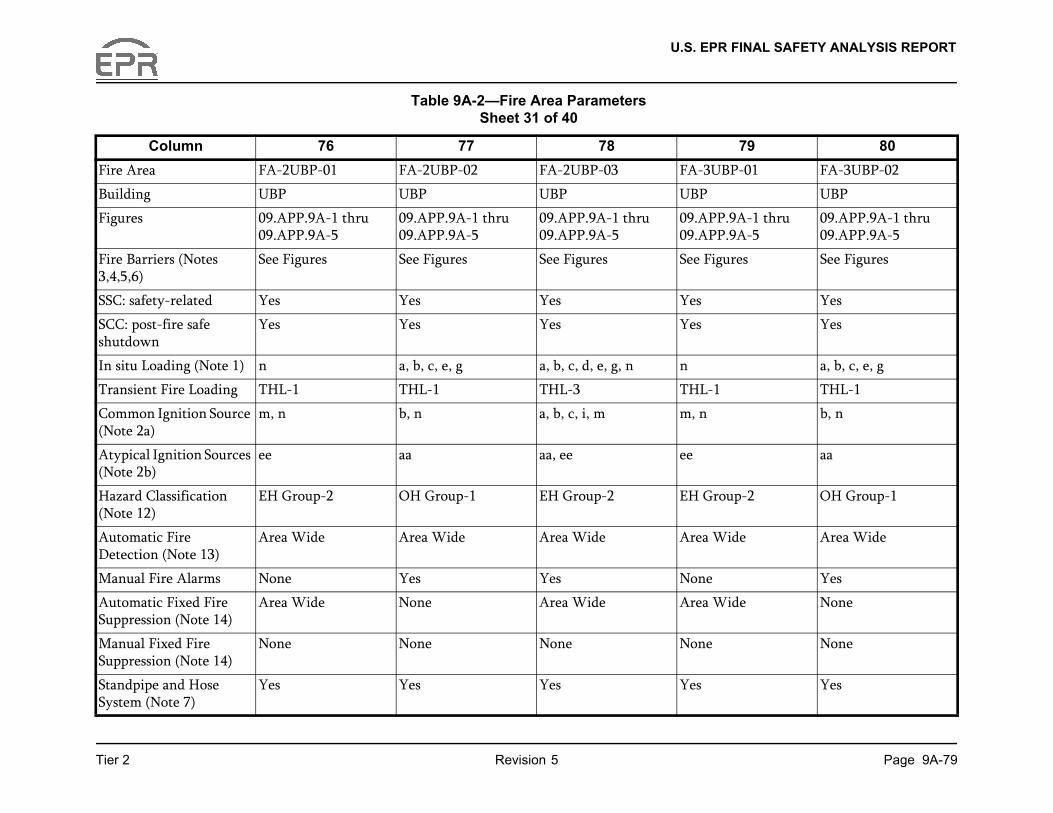
U.S. EPR FINAL SAFETY ANALYSIS REPORT
Page 9A-79
79 80
-01 FA-3UBP-02
UBP
A-1 thru A-5
09.APP.9A-1 thru 09.APP.9A-5
res See Figures
Yes
Yes
a, b, c, e, g
THL-1
b, n
aa
p-2 OH Group-1
de Area Wide
Yes
de None
None
Yes
Tier 2 Revision 5
Column 76 77 78
Fire Area FA-2UBP-01 FA-2UBP-02 FA-2UBP-03 FA-3UBP
Building UBP UBP UBP UBP
Figures 09.APP.9A-1 thru 09.APP.9A-5
09.APP.9A-1 thru 09.APP.9A-5
09.APP.9A-1 thru 09.APP.9A-5
09.APP.909.APP.9
Fire Barriers (Notes 3,4,5,6)
See Figures See Figures See Figures See Figu
SSC: safety-related Yes Yes Yes Yes
SCC: post-fire safe shutdown
Yes Yes Yes Yes
In situ Loading (Note 1) n a, b, c, e, g a, b, c, d, e, g, n n
Transient Fire Loading THL-1 THL-1 THL-3 THL-1
Common Ignition Source (Note 2a)
m, n b, n a, b, c, i, m m, n
Atypical Ignition Sources (Note 2b)
ee aa aa, ee ee
Hazard Classification (Note 12)
EH Group-2 OH Group-1 EH Group-2 EH Grou
Automatic Fire Detection (Note 13)
Area Wide Area Wide Area Wide Area Wi
Manual Fire Alarms None Yes Yes None
Automatic Fixed Fire Suppression (Note 14)
Area Wide None Area Wide Area Wi
Manual Fixed Fire Suppression (Note 14)
None None None None
Standpipe and Hose System (Note 7)
Yes Yes Yes Yes
Table 9A-2—Fire Area Parameters Sheet 31 of 40

U.S. EPR FINAL SAFETY ANALYSIS REPORT
Page 9A-80
79 80
Yes
None
Yes
None
h
bb
Yes
None
Tier 2 Revision 5
Column 76 77 78
Portable Fire Extinguishers (Note 8)
Yes Yes Yes Yes
Suppression Effects None None None None
Plant Drains Yes Yes Yes Yes
Radiological Effects (Note 15)
None None None None
HVAC (Note 9) h h h h
Emergency Lighting (Note 10)
bb bb aa bb
Communication (Note 11)
Yes Yes Yes Yes
Engineering Evaluations None None None None
Table 9A-2—Fire Area Parameters Sheet 32 of 40
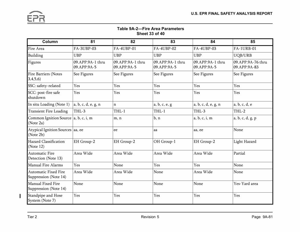
U.S. EPR FINAL SAFETY ANALYSIS REPORT
Page 9A-81
84 85
-03 FA-1URB-01
UQB/URB
A-1 thru A-5
09.APP.9A-76 thru 09.APP.9A-83
res See Figures
Yes
Yes
e, g, n a, b, c, d, e
THL-2
m a, b, c, d, g, p
None
p-2 Light Hazard
de Partial
None
de None
Yes-Yard area
Yes
Tier 2 Revision 5
Column 81 82 83
Fire Area FA-3UBP-03 FA-4UBP-01 FA-4UBP-02 FA-4UBP
Building UBP UBP UBP UBP
Figures 09.APP.9A-1 thru 09.APP.9A-5
09.APP.9A-1 thru 09.APP.9A-5
09.APP.9A-1 thru 09.APP.9A-5
09.APP.909.APP.9
Fire Barriers (Notes 3,4,5,6)
See Figures See Figures See Figures See Figu
SSC: safety-related Yes Yes Yes Yes
SCC: post-fire safe shutdown
Yes Yes Yes Yes
In situ Loading (Note 1) a, b, c, d, e, g, n n a, b, c, e, g a, b, c, d,
Transient Fire Loading THL-3 THL-1 THL-1 THL-3
Common Ignition Source (Note 2a)
a, b, c, i, m m, n b, n a, b, c, i,
Atypical Ignition Sources (Note 2b)
aa, ee ee aa aa, ee
Hazard Classification (Note 12)
EH Group-2 EH Group-2 OH Group-1 EH Grou
Automatic Fire Detection (Note 13)
Area Wide Area Wide Area Wide Area Wi
Manual Fire Alarms Yes None Yes Yes
Automatic Fixed Fire Suppression (Note 14)
Area Wide Area Wide None Area Wi
Manual Fixed Fire Suppression (Note 14)
None None None None
Standpipe and Hose System (Note 7)
Yes Yes Yes Yes
Table 9A-2—Fire Area Parameters Sheet 33 of 40

U.S. EPR FINAL SAFETY ANALYSIS REPORT
Page 9A-82
84 85
Yes
None
None
None
l
aa
Yes
No
Tier 2 Revision 5
Column 81 82 83
Portable Fire Extinguishers (Note 8)
Yes Yes Yes Yes
Suppression Effects None None None None
Plant Drains Yes Yes Yes Yes
Radiological Effects (Note 15)
None None None None
HVAC (Note 9) h h h h
Emergency Lighting (Note 10)
aa bb bb aa
Communication (Note 11)
Yes Yes Yes Yes
Engineering Evaluations None None None None
Table 9A-2—Fire Area Parameters Sheet 34 of 40

U.S. EPR FINAL SAFETY ANALYSIS REPORT
Page 9A-83
89 90
-01 FA-UKE-02
UKE
A-98 thru A-106
09.APP.9A-98 thru 09.APP.9A-106
res See Figures
None
None
a, b, d
THL-1
c, n
None
zard Light Hazard
Area Wide
None
None
None
Yes
Tier 2 Revision 5
Column 86 87 88
Fire Area FA-2URB-01 FA-3URB-01 FA-4URB-01 FA-UKE
Building UQB/URB UQB/URB UQB/URB UKE
Figures 09.APP.9A-76 thru 09.APP.9A-83
09.APP.9A-76 thru 09.APP.9A-83
09.APP.9A-76 thru 09.APP.9A-83
09.APP.909.APP.9
Fire Barriers (Notes 3,4,5,6)
See Figures See Figures See Figures See Figu
SSC: safety-related Yes Yes Yes None
SCC: post-fire safe shutdown
Yes Yes Yes None
In situ Loading (Note 1) a, b, c, d, e a, b, c, d, e a, b, c, d, e a, b
Transient Fire Loading THL-2 THL-2 THL-2 THL-1
Common Ignition Source (Note 2a)
a, b, c, d, g, p a, b, c, d, g, p a, b, c, d, g, p n
Atypical Ignition Sources (Note 2b)
None None None None
Hazard Classification (Note 12)
Light Hazard Light Hazard Light Hazard Light Ha
Automatic Fire Detection (Note 13)
Partial Partial Partial None
Manual Fire Alarms None None None Yes
Automatic Fixed Fire Suppression (Note 14)
None None None None
Manual Fixed Fire Suppression (Note 14)
None None None None
Standpipe and Hose System (Note 7)
Yes Yes Yes Yes
Table 9A-2—Fire Area Parameters Sheet 35 of 40

U.S. EPR FINAL SAFETY ANALYSIS REPORT
Page 9A-84
89 90
Yes
None
Yes
None
j
None
Yes
None
Tier 2 Revision 5
Column 86 87 88
Portable Fire Extinguishers (Note 8)
Yes Yes Yes Yes
Suppression Effects None None None None
Plant Drains None None None Yes
Radiological Effects (Note 15)
None None None Yes
HVAC (Note 9) l l l j
Emergency Lighting (Note 10)
aa aa aa aa
Communication (Note 11)
Yes Yes Yes Yes
Engineering Evaluations None None None None
Table 9A-2—Fire Area Parameters Sheet 36 of 40
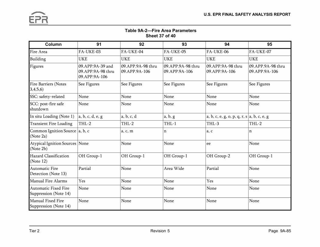
U.S. EPR FINAL SAFETY ANALYSIS REPORT
Page 9A-85
94 95
-06 FA-UKE-07
UKE
A-98 thru A-106
09.APP.9A-98 thru 09.APP.9A-106
res See Figures
None
None
g, o, p, q, r, s a, b, c, e, g
THL-2
n
None
p-2 OH Group-1
None
None
None
None
Tier 2 Revision 5
Column 91 92 93
Fire Area FA-UKE-03 FA-UKE-04 FA-UKE-05 FA-UKE
Building UKE UKE UKE UKE
Figures 09.APP.9A-39 and 09.APP.9A-98 thru 09.APP.9A-106
09.APP.9A-98 thru 09.APP.9A-106
09.APP.9A-98 thru 09.APP.9A-106
09.APP.909.APP.9
Fire Barriers (Notes 3,4,5,6)
See Figures See Figures See Figures See Figu
SSC: safety-related None None None None
SCC: post-fire safe shutdown
None None None None
In situ Loading (Note 1) a, b, c, d, e, g a, b, c, d a, b, g a, b, c, e,
Transient Fire Loading THL-2 THL-2 THL-1 THL-3
Common Ignition Source (Note 2a)
a, b, c a, c, m n a, c
Atypical Ignition Sources (Note 2b)
None None None ee
Hazard Classification (Note 12)
OH Group-1 OH Group-1 OH Group-1 OH Grou
Automatic Fire Detection (Note 13)
Partial None Area Wide Partial
Manual Fire Alarms Yes None None Yes
Automatic Fixed Fire Suppression (Note 14)
None None None None
Manual Fixed Fire Suppression (Note 14)
None None None None
Table 9A-2—Fire Area Parameters Sheet 37 of 40
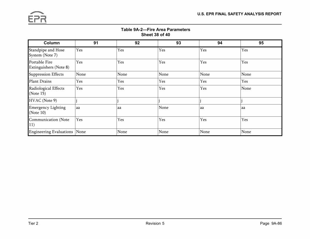
U.S. EPR FINAL SAFETY ANALYSIS REPORT
Page 9A-86
94 95
Yes
Yes
None
Yes
None
j
aa
Yes
None
Tier 2 Revision 5
Column 91 92 93
Standpipe and Hose System (Note 7)
Yes Yes Yes Yes
Portable Fire Extinguishers (Note 8)
Yes Yes Yes Yes
Suppression Effects None None None None
Plant Drains Yes Yes Yes Yes
Radiological Effects (Note 15)
Yes Yes Yes Yes
HVAC (Note 9) j j j j
Emergency Lighting (Note 10)
aa aa None aa
Communication (Note 11)
Yes Yes Yes Yes
Engineering Evaluations None None None None
Table 9A-2—Fire Area Parameters Sheet 38 of 40
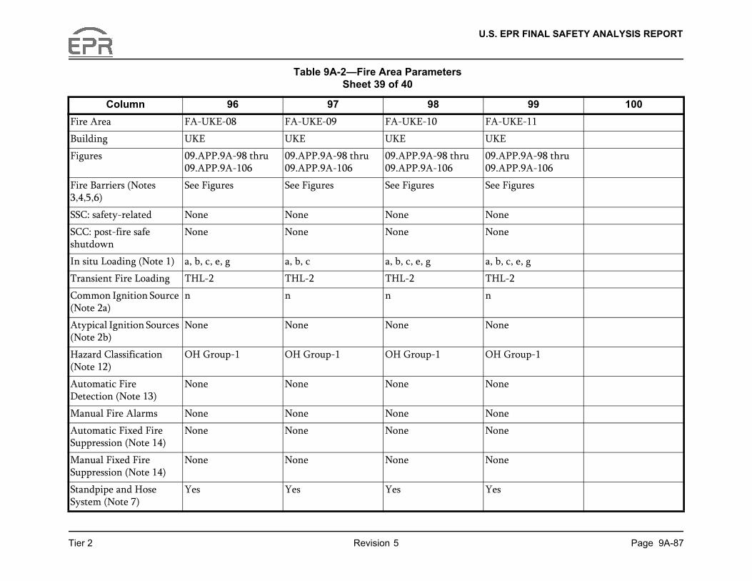
U.S. EPR FINAL SAFETY ANALYSIS REPORT
Page 9A-87
99 100
-11
A-98 thru A-106
res
g
p-1
Tier 2 Revision 5
Column 96 97 98
Fire Area FA-UKE-08 FA-UKE-09 FA-UKE-10 FA-UKE
Building UKE UKE UKE UKE
Figures 09.APP.9A-98 thru 09.APP.9A-106
09.APP.9A-98 thru 09.APP.9A-106
09.APP.9A-98 thru 09.APP.9A-106
09.APP.909.APP.9
Fire Barriers (Notes 3,4,5,6)
See Figures See Figures See Figures See Figu
SSC: safety-related None None None None
SCC: post-fire safe shutdown
None None None None
In situ Loading (Note 1) a, b, c, e, g a, b, c a, b, c, e, g a, b, c, e,
Transient Fire Loading THL-2 THL-2 THL-2 THL-2
Common Ignition Source (Note 2a)
n n n n
Atypical Ignition Sources (Note 2b)
None None None None
Hazard Classification (Note 12)
OH Group-1 OH Group-1 OH Group-1 OH Grou
Automatic Fire Detection (Note 13)
None None None None
Manual Fire Alarms None None None None
Automatic Fixed Fire Suppression (Note 14)
None None None None
Manual Fixed Fire Suppression (Note 14)
None None None None
Standpipe and Hose System (Note 7)
Yes Yes Yes Yes
Table 9A-2—Fire Area Parameters Sheet 39 of 40

U.S. EPR FINAL SAFETY ANALYSIS REPORT
Page 9A-88
99 100
Tier 2 Revision 5
Notes:
1. In-situ loading:
a. Miscellaneous Cable Insulation.
b. Miscellaneous Plastic and Rubber.
c. Miscellaneous Wire and Plastic Components (Panels).
d. Lubricants and Hydraulic Fluids.
e. Electrical Cabinets.
f. Flammable Gases (Hydrogen).
g. Electrical Cable Insulation (Cable Trays).
Column 96 97 98
Portable Fire Extinguishers (Note 8)
Yes Yes Yes Yes
Suppression Effects None None None None
Plant Drains Yes Yes Yes Yes
Radiological Effects (Note 15)
None Yes None None
HVAC (Note 9) j j j j
Emergency Lighting (Note 10)
aa aa aa aa
Communication (Note 11)
Yes Yes Yes Yes
Engineering Evaluations None None None None
Table 9A-2—Fire Area Parameters Sheet 40 of 40

U.S. EPR FINAL SAFETY ANALYSIS REPORT
Page 9A-89
Tier 2 Revision 5h. Charcoal (Filters).
i. Air Compressors.
j. HVAC Subsystem Components.
k. Transformers (Dry).
l. Transformers (Oil-filled).
m. Battery Cases.
n. Diesel Fuel Oil.
o. Paints, Solvents and Cleaning Fluids.
p. Clothing (Cotton and Synthetic Blends).
q. Clothing (Rubber and Plastic).
r. Paper Records, Procedures and Files.
s. Furniture and Appliances.
t. Air Handiling Units.
2a. Common Ignition Sources:
a. Low to Medium Voltage Electrical Circuits.
b. General Electrical and Control Cabinets.
c. Electric Motors.
d. Pumps.
e. Air Compressors.
f. Indoor Oil-filled Transforms.
U.S. EPR FINAL SAFETY ANALYSIS REPORT
Page 9A-90
vided.
Tier 2 Revision 5
g. Electrical Switchgear Cabinets.
h. Reactor Protection System MG sets.
i. Diesel Generators.
j. Battery Banks.
k. Boiler Heating Units.
l. Electric Dryers.
m. HVAC subsystem components.
n. Low Voltage Electrical Circuits.
o. Air Handling Units.
p. Transformers (Dry).
2b. Atypical Ignition Sources:
aa. Arcing Electrical Faults.
bb. Hydrogen Storage Tanks.
cc. Hydrogen Piping.
dd. T/G Exciter / Hydrogen.
ee. Liquid Fuels (spills).
ff. Outdoor Oil-filled Transformers.
3. Barrier Ratings (See “Fire Barrier Location” Figure 09.APP.9A)
4. Doors:
For 1 hour fire rated barriers, minimum 1 hour fire rated door assemblies are pro

U.S. EPR FINAL SAFETY ANALYSIS REPORT
Page 9A-91
ovided.
vided.
.
led or otherwise closed with rated n this fire area will be justified by
at all areas within each fire area can ith a 30 foot hose stream.
al fire fighting activities.
m (SBVSE).
Tier 2 Revision 5
For 2 hour fire rated barriers, minimum 1.5 hour fire rated door assemblies are pr
For 3 hour fire rated barriers, minimum 3 hour fire rated door assemblies are pro
5. Dampers:
For 1 hour fire rated barriers, minimum 1 hour fire rated dampers are provided.
For 2 hour fire rated barriers, minimum 1.5 hour fire rated dampers are provided
For 3 hour fire rated barriers, minimum 3 hour fire rated dampers are provided.
6. Penetrations:
Penetrations through fire rated walls, floors, and ceilings of each fire area are seapenetration seal assemblies. Any non-rated penetrations through rated barriers iengineering evaluations.
7. Standpipe and Hose Stations:
Class 3 standpipe and hose stations are provided throughout each building such thbe reached with at least one effective hose stream, considering 100 feet of hose w
8. Portable Fire Extinguishers:
Portable fire extinguishers are available throughout the building to support manu
9. HVAC:
a. Section 9.4.1 - Main Control Room Air Conditioning System.
b. Section 9.4.2 - Fuel Building Ventilation System.
c. Section 9.4.3 - Nuclear Auxiliary Building Ventilation System.
d. Section 9.4.5 - Safeguard Building Controlled-Area Ventilation System.
e. Section 9.4.6 - Electrical Division of Safeguard Building Ventilation Syste
f. Section 9.4.7 - Containment Building Ventilation System.
U.S. EPR FINAL SAFETY ANALYSIS REPORT
Page 9A-92
.
.
em.
m.
which provide minimum ress path in the event of a loss of the
f interruptible EDG-backed lighting f the normal plant lighting system
f interruptible EDG-backed lighting of the normal plant lighting system the MCR and the RSS.
nsists of uninterruptible UPS-backed
e public address and paging system, d portable radio communications.
Tier 2 Revision 5
g. Section 9.4.8 - Radioactive Waste Processing Building Ventilation System
h. Section 9.4.9 - Emergency Power Generating Building Ventilation System
i. Section 9.4.13 - Smoke Confinement System.
j. Section 9.4.14 - Access Building Ventilation System.
k. Section 9.4.12 - Main Steam and Feedwater Valve Room Ventilation Syst
l. Section 9.4.11 - Essential Service Water Pump Building Ventilation Syste
10. Emergency Lighting:
aa. Self-contained, battery backed fixtures installed throughout the fire area illumination for a 90 minute period to make sure that a safe access and egnormal plant lighting system.
bb. Is provided by the emergency lighting subsystem. This lighting consists oprovided for operation of safety-related equipment in the event of a loss o(TBV).
cc. Is provided by the emergency lighting subsystem. This lighting consists oprovided for operation of safety-related equipment in the event of a loss (TBV). Emergency lighting is also provided for the egress route between
dd. Is provided by the special emergency lighting subsystem. This lighting colighting provided for operation of safety-related equipment.
11. Communication:
One or more of the following methods of communication are available: plant-widin-plant telephone system, external communication links to the outside world, an
12. Hazard Classification:
See Section 9A.2.2 for definition of hazard classifications.
- Light Hazard.
U.S. EPR FINAL SAFETY ANALYSIS REPORT
Page 9A-93
l detection is indicated, is contained
where partial fire suppression is
e radiological effects from a fire and
ces of a fire will be evaluated by the
Next File
Tier 2 Revision 5
- Ordinary Hazard (OH Group-1).
- Ordinary Hazard (OH Group-2).
- Extra Hazard (EH Group-1).
- Extra Hazard (EH Group-2).
13. Automatic Fire Detection:
The type of detection provided, and the extent of detection coverage where partiain Section 9A.3.
14. Automatic Fixed Fire Suppression and Manual Fixed Fire Suppression:
The type of fire suppression provided, and the extent of fire suppression coverageindicated, is contained in Section 9A.3.
15. This indicates the potential presence of radiological sources in a fire area. Possibl
the need for additional in-depth fire protection features to mitigate the consequen
COL applicant as a part of the final FHA (refer to Section 9.5.1.3).