7 digital circuits
DESCRIPTION
Digital CircuitsTRANSCRIPT

ELE2120 Digital Circuits and Systems
Tutorial Note 9
Outline
1. Exercise(1) Sequential Circuit Analysis
2. Exercise (2) Sequential Circuit Analysis
4. Ref. Construction of State Diagram
3. Exercise (3) Sequential Circuit Analysis
5. Ref. State Reduction
6. Exercise (4) Sequential Circuit Design
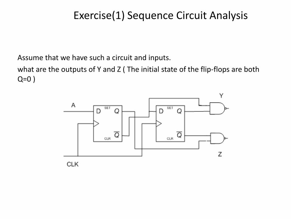
Exercise(1) Sequence Circuit Analysis
Assume that we have such a circuit and inputs.
what are the outputs of Y and Z ( The initial state of the flip-flops are both Q=0 )
1 2 1 2Y Q Q Q Q 1 2 1 2Z Q Q Q Q
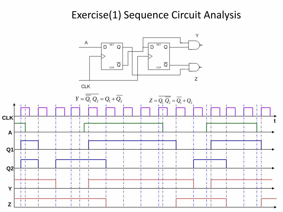
Exercise(1) Sequence Circuit Analysis
CLK
Z
A
Q1
Q2
Y
t
Exercise(1) Sequence Circuit Analysis
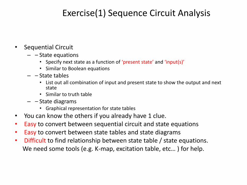
• Sequential Circuit– – State equations
• Specify next state as a function of ‘present state’ and ‘input(s)’• Similar to Boolean equations
– – State tables• List out all combination of input and present state to show the output and next
state• Similar to truth table
– – State diagrams• Graphical representation for state tables
• You can know the others if you already have 1 clue.• Easy to convert between sequential circuit and state equations• Easy to convert between state tables and state diagrams• Difficult to find relationship between state table / state equations.
We need some tools (e.g. K-map, excitation table, etc… ) for help.
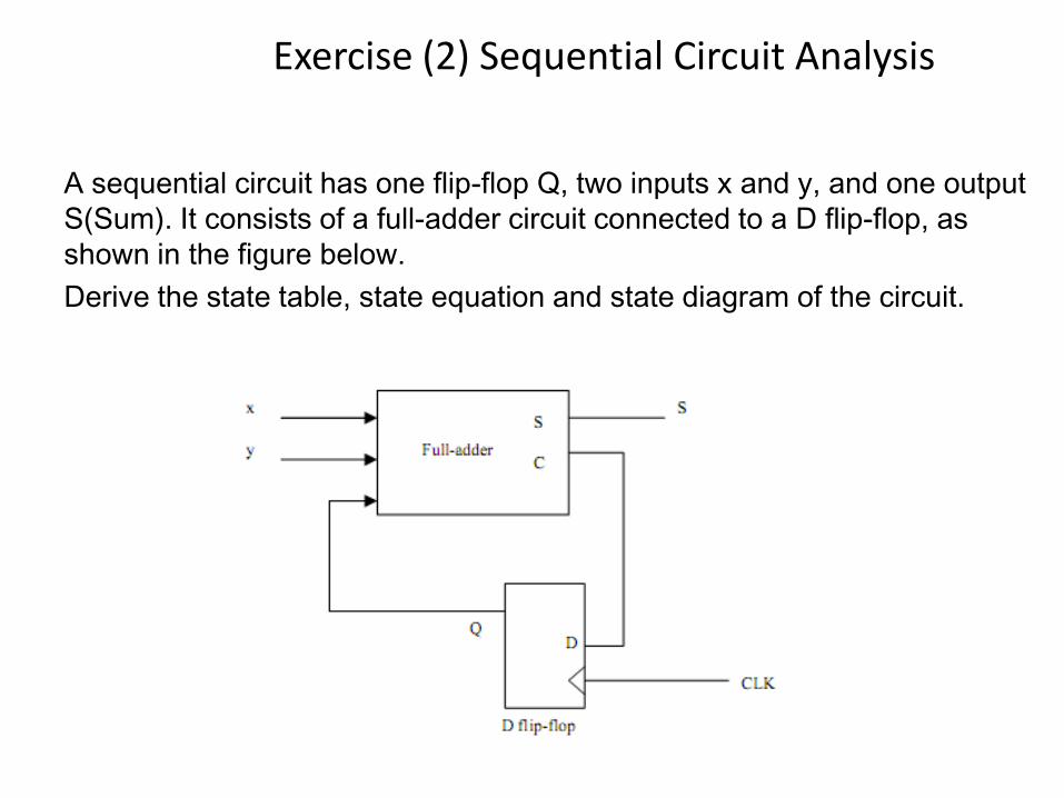
Exercise (2) Sequential Circuit Analysis
A sequential circuit has one flip-flop Q, two inputs x and y, and one output
S(Sum). It consists of a full-adder circuit connected to a D flip-flop, as
shown in the figure below.
Derive the state table, state equation and state diagram of the circuit.
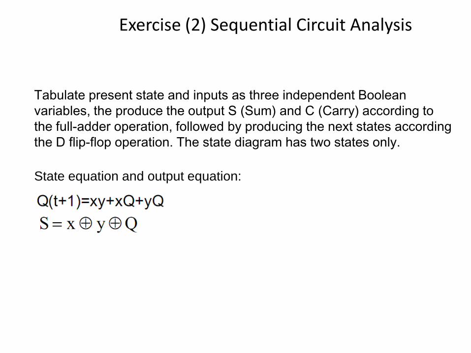
Exercise (2) Sequential Circuit Analysis
Tabulate present state and inputs as three independent Boolean
variables, the produce the output S (Sum) and C (Carry) according to
the full-adder operation, followed by producing the next states according
the D flip-flop operation. The state diagram has two states only.
State equation and output equation:
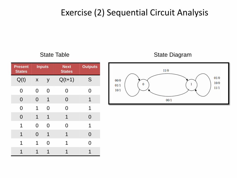
Exercise (2) Sequential Circuit Analysis
Present
States
Inputs Next
States
Outputs
Q(t) x y Q(t+1) S
0 0 0 0 0
0 0 1 0 1
0 1 0 0 1
0 1 1 1 0
1 0 0 0 1
1 0 1 1 0
1 1 0 1 0
1 1 1 1 1
State Table State Diagram
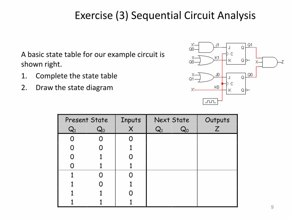
Exercise (3) Sequential Circuit Analysis
9
A basic state table for our example circuit is shown right.
1. Complete the state table
2. Draw the state diagram
Present State Inputs Next State Outputs
Q1 Q0 X Q1 Q0 Z
0 0 0
0 0 1
0 1 0
0 1 1
1 0 0
1 0 1
1 1 0
1 1 1
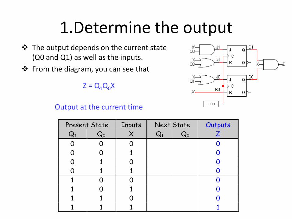
1.Determine the output The output depends on the current state
(Q0 and Q1) as well as the inputs.
From the diagram, you can see that
Z = Q1Q0X
Output at the current time
Present State Inputs Next State Outputs
Q1 Q0 X Q1 Q0 Z
0 0 0 0
0 0 1 0
0 1 0 0
0 1 1 0
1 0 0 0
1 0 1 0
1 1 0 0
1 1 1 1
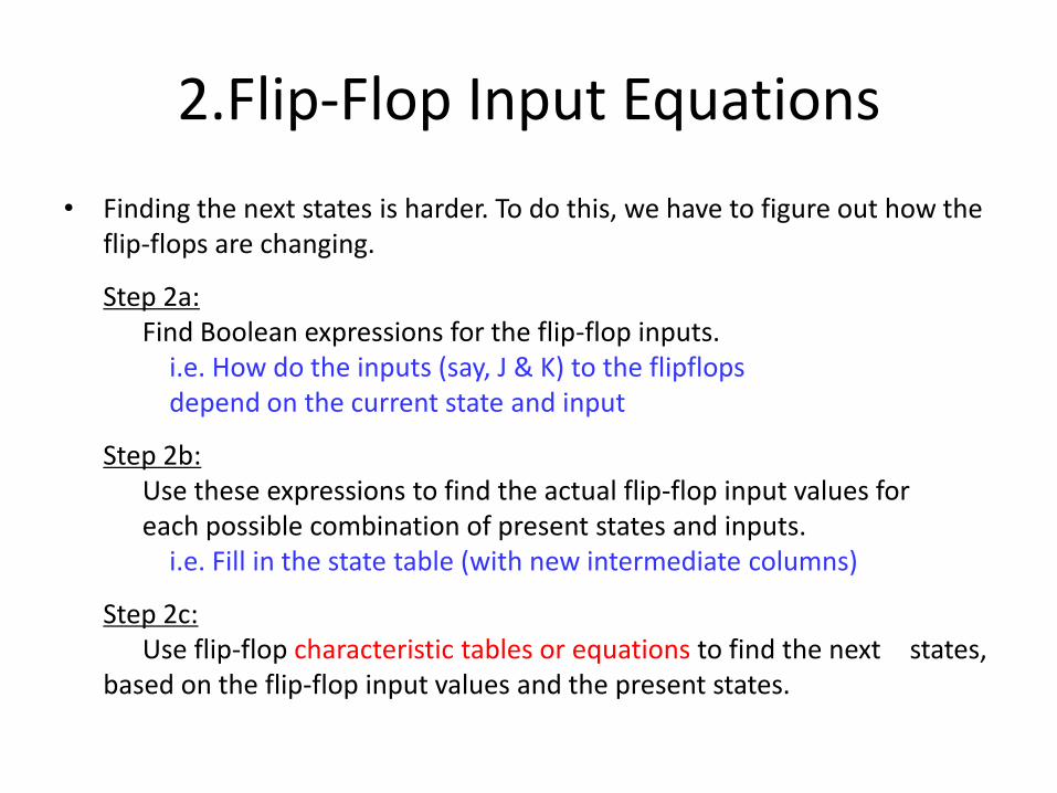
2.Flip-Flop Input Equations
• Finding the next states is harder. To do this, we have to figure out how the flip-flops are changing.
Step 2a:Find Boolean expressions for the flip-flop inputs.
i.e. How do the inputs (say, J & K) to the flipflops depend on the current state and input
Step 2b:Use these expressions to find the actual flip-flop input values for each possible combination of present states and inputs.
i.e. Fill in the state table (with new intermediate columns)
Step 2c:Use flip-flop characteristic tables or equations to find the next states,
based on the flip-flop input values and the present states.
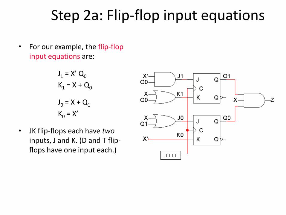
Step 2a: Flip-flop input equations
• For our example, the flip-flop input equations are:
J1 = X’ Q0
K1 = X + Q0
J0 = X + Q1
K0 = X’
• JK flip-flops each have twoinputs, J and K. (D and T flip-flops have one input each.)
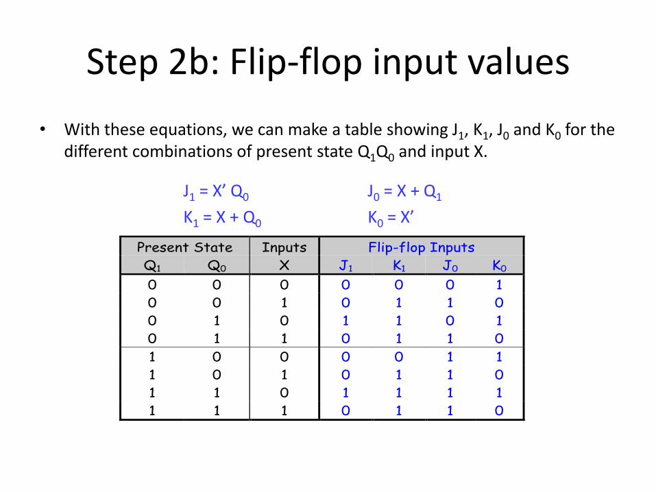
Step 2b: Flip-flop input values
• With these equations, we can make a table showing J1, K1, J0 and K0 for the different combinations of present state Q1Q0 and input X.
J1 = X’ Q0 J0 = X + Q1
K1 = X + Q0 K0 = X’
Present State Inputs Flip-flop Inputs
Q1 Q0 X J1 K1 J0 K0
0 0 0 0 0 0 1
0 0 1 0 1 1 0
0 1 0 1 1 0 1
0 1 1 0 1 1 0
1 0 0 0 0 1 1
1 0 1 0 1 1 0
1 1 0 1 1 1 1
1 1 1 0 1 1 0
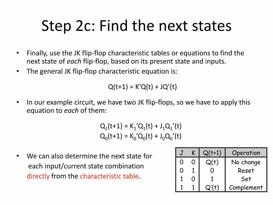
Step 2c: Find the next states
• Finally, use the JK flip-flop characteristic tables or equations to find the next state of each flip-flop, based on its present state and inputs.
• The general JK flip-flop characteristic equation is:
Q(t+1) = K’Q(t) + JQ’(t)
• In our example circuit, we have two JK flip-flops, so we have to apply this equation to each of them:
Q1(t+1) = K1’Q1(t) + J1Q1’(t)
Q0(t+1) = K0’Q0(t) + J0Q0’(t)
• We can also determine the next state for
each input/current state combination
directly from the characteristic table.
J K Q(t+1) Operation
0 0 Q(t) No change
0 1 0 Reset
1 0 1 Set
1 1 Q’(t) Complement
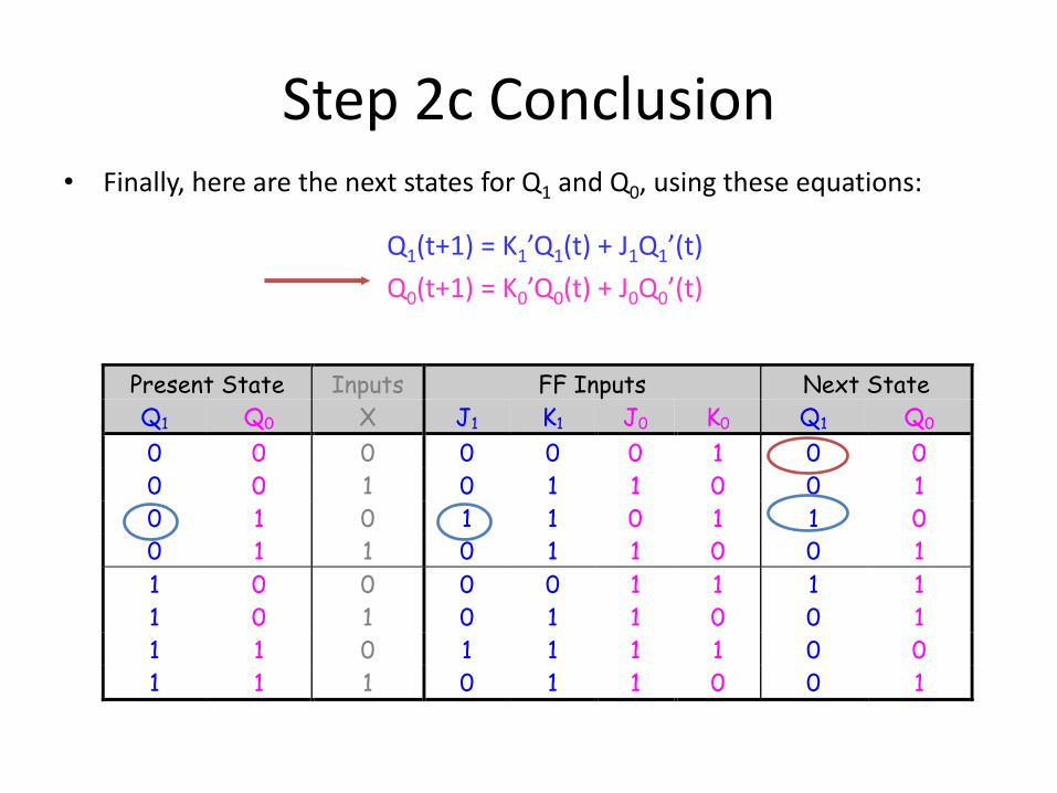
Step 2c Conclusion• Finally, here are the next states for Q1 and Q0, using these equations:
Q1(t+1) = K1’Q1(t) + J1Q1’(t)
Q0(t+1) = K0’Q0(t) + J0Q0’(t)
Present State Inputs FF Inputs Next State
Q1 Q0 X J1 K1 J0 K0 Q1 Q0
0 0 0 0 0 0 1 0 0
0 0 1 0 1 1 0 0 1
0 1 0 1 1 0 1 1 0
0 1 1 0 1 1 0 0 1
1 0 0 0 0 1 1 1 1
1 0 1 0 1 1 0 0 1
1 1 0 1 1 1 1 0 0
1 1 1 0 1 1 0 0 1
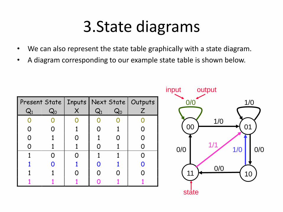
3.State diagrams• We can also represent the state table graphically with a state diagram.
• A diagram corresponding to our example state table is shown below.
Present State Inputs Next State Outputs
Q1 Q0 X Q1 Q0 Z
0 0 0 0 0 0
0 0 1 0 1 0
0 1 0 1 0 0
0 1 1 0 1 0
1 0 0 1 1 0
1 0 1 0 1 0
1 1 0 0 0 0
1 1 1 0 1 1
00 01
1011
1/0
0/00/0
0/0
0/0 1/0
1/01/1
input output
state
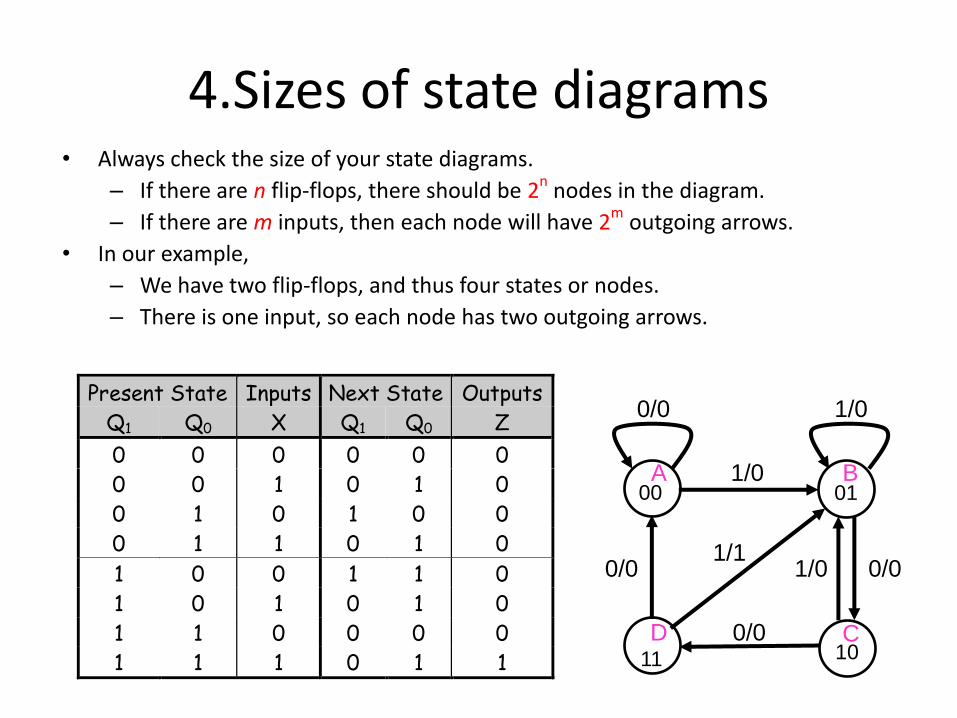
4.Sizes of state diagrams• Always check the size of your state diagrams.
– If there are n flip-flops, there should be 2n
nodes in the diagram.
– If there are m inputs, then each node will have 2m outgoing arrows.
• In our example,
– We have two flip-flops, and thus four states or nodes.
– There is one input, so each node has two outgoing arrows.
Present State Inputs Next State Outputs
Q1 Q0 X Q1 Q0 Z
0 0 0 0 0 0
0 0 1 0 1 0
0 1 0 1 0 0
0 1 1 0 1 0
1 0 0 1 1 0
1 0 1 0 1 0
1 1 0 0 0 0
1 1 1 0 1 1
00 01
1011
1/0
0/00/0
0/0
0/0 1/0
1/01/1
A
D
B
C
5.State diagram
Construction
•Identify all possible states (they are the nodes)
• Identify how the process moves from a state to
another (they are the links)
• Identify how the outputs are generated
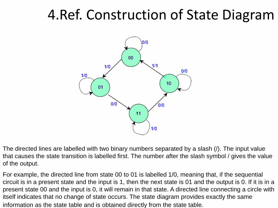
4.Ref. Construction of State Diagram
The directed lines are labelled with two binary numbers separated by a slash (/). The input value
that causes the state transition is labelled first. The number after the slash symbol / gives the value
of the output.
For example, the directed line from state 00 to 01 is labelled 1/0, meaning that, if the sequential
circuit is in a present state and the input is 1, then the next state is 01 and the output is 0. If it is in a
present state 00 and the input is 0, it will remain in that state. A directed line connecting a circle with
itself indicates that no change of state occurs. The state diagram provides exactly the same
information as the state table and is obtained directly from the state table.
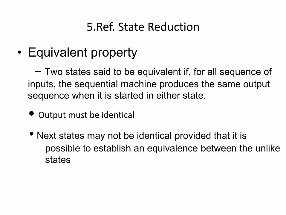
5.Ref. State Reduction
• Equivalent property
– Two states said to be equivalent if, for all sequence of
inputs, the sequential machine produces the same output
sequence when it is started in either state.
• Output must be identical
• Next states may not be identical provided that it is
possible to establish an equivalence between the unlike
states
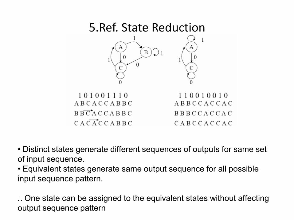
5.Ref. State Reduction
• Distinct states generate different sequences of outputs for same set
of input sequence.
• Equivalent states generate same output sequence for all possible
input sequence pattern.
∴ One state can be assigned to the equivalent states without affecting
output sequence pattern
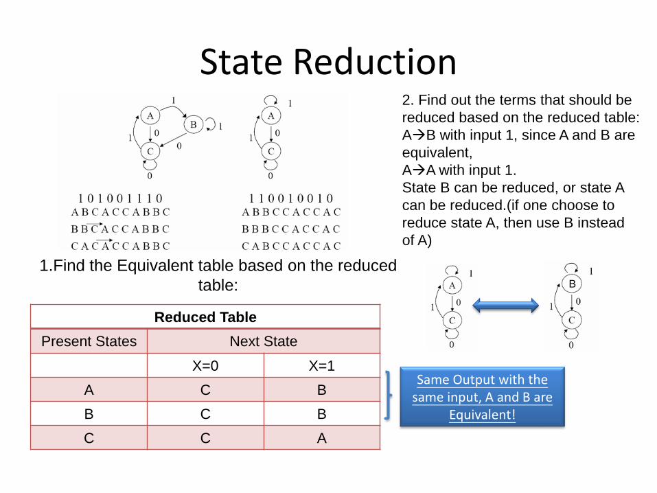
State Reduction
Reduced Table
Present States Next State
X=0 X=1
A C B
B C B
C C A
1.Find the Equivalent table based on the reduced
table:
Same Output with the same input, A and B are
Equivalent!
2. Find out the terms that should be
reduced based on the reduced table:
AB with input 1, since A and B are
equivalent,
AA with input 1.
State B can be reduced, or state A
can be reduced.(if one choose to
reduce state A, then use B instead
of A)
B
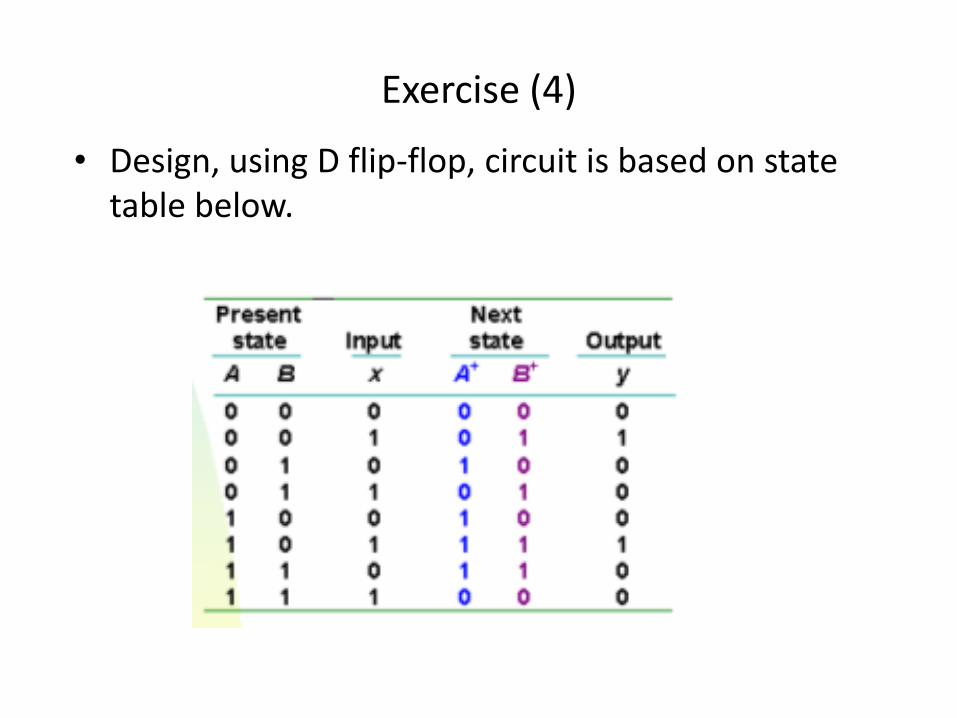
Exercise (4)
• Design, using D flip-flop, circuit is based on state table below.
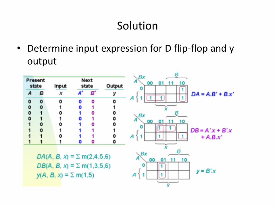
Solution
• Determine input expression for D flip-flop and y output
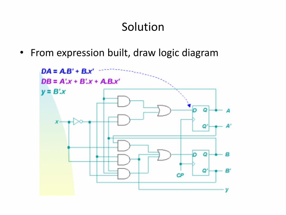
Solution
• From expression built, draw logic diagram