digital integrated circuits { eecs 312 - robert dickrobertdick.org/eecs312/lectures/dic-l11.pdf ·...
TRANSCRIPT
Digital Integrated Circuits – EECS 312
http://robertdick.org/eecs312/
Teacher: Robert DickOffice: 2417-E EECSEmail: [email protected]: 734–763–3329Cellphone: 847–530–1824
GSI: Shengshou LuOffice: 2725 BBBEmail: [email protected]
HW engineers SW engineers
0
1
2
3
4
5
6
7
8
9
10
200 220 240 260 280 300
Cu
rre
nt
(mA
)
Time (seconds)
Typical Current Draw 1 sec Heartbeat
30 beats per sample
Sampling andRadio Transmission
9 - 15 mA
Heartbeat1 - 2 mA
Radio Receive for
Mesh Maintenance
2 - 6 mA
Low Power Sleep0.030 - 0.050 mA
Year of announcement
1950 1960 1970 1980 1990 2000 2010
Pow
er d
ensi
ty (
Wat
ts/c
m2 )
0
2
4
6
8
10
12
14
Bipolar
CMOS
VacuumIBM 360
IBM 370 IBM 3033
IBM ES9000
Fujitsu VP2000
IBM 3090S
NTT
Fujitsu M-780
IBM 3090
CDC Cyber 205IBM 4381
IBM 3081Fujitsu M380
IBM RY5
IBM GP
IBM RY6
Apache
Pulsar
Merced
IBM RY7
IBM RY4
Pentium II(DSIP)
T-Rex
Squadrons
Pentium 4
Mckinley
Prescott
Jayhawk(dual)
IBM Z9
Non-idealitiesDCVSL
Dynamic CMOSCharge sharing
Homework
Announcements
Logical effort.
Homework 3, problem 9 will be moved to Homework 4.
Review DeMorgan’s Laws and gate design.
2 Robert Dick Digital Integrated Circuits
Non-idealitiesDCVSL
Dynamic CMOSCharge sharing
Homework
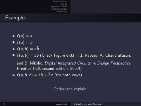
Examples
f (a) = a.
f (a) = a
f (a, b) = ab
f (a, b) = ab (Check Figure 6-33 in J. Rabaey, A. Chandrakasan,
and B. Nikolic. Digital Integrated Circuits: A Design Perspective.Prentice-Hall, second edition, 2003!)
f (a, b, c) = ab + bc (try both ways).
Derive and explain.
3 Robert Dick Digital Integrated Circuits
Non-idealitiesDCVSL
Dynamic CMOSCharge sharing
Homework
Lecture plan
1. Non-idealities
2. DCVSL
3. Dynamic CMOS
4. Charge sharing
5. Homework
4 Robert Dick Digital Integrated Circuits
Non-idealitiesDCVSL
Dynamic CMOSCharge sharing
Homework
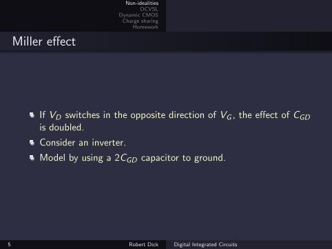
Miller effect
If VD switches in the opposite direction of VG , the effect of CGD
is doubled.
Consider an inverter.
Model by using a 2CGD capacitor to ground.
5 Robert Dick Digital Integrated Circuits
Non-idealitiesDCVSL
Dynamic CMOSCharge sharing
Homework
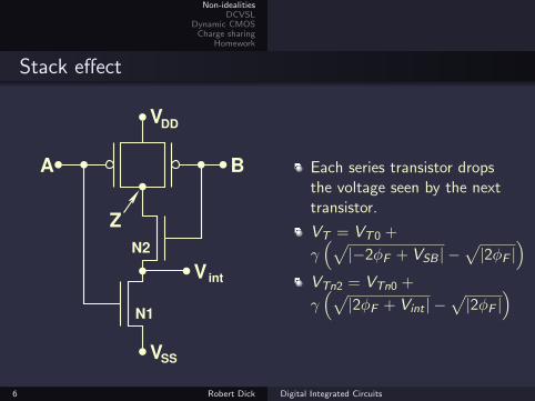
Stack effect
V int
VSS
VDD
A B
Z
N2
N1
Each series transistor dropsthe voltage seen by the nexttransistor.
VT = VT0 +
γ(√|−2φF + VSB | −
√|2φF |
)VTn2 = VTn0 +
γ(√|2φF + Vint | −
√|2φF |
)
6 Robert Dick Digital Integrated Circuits
Non-idealitiesDCVSL
Dynamic CMOSCharge sharing
Homework
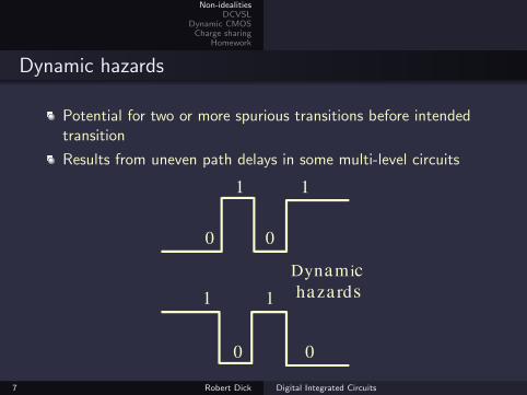
Dynamic hazards
Potential for two or more spurious transitions before intendedtransition
Results from uneven path delays in some multi-level circuits
Dynam ic
haza rds
1
0 0
1
1 1
0 0
7 Robert Dick Digital Integrated Circuits
Non-idealitiesDCVSL
Dynamic CMOSCharge sharing
Homework
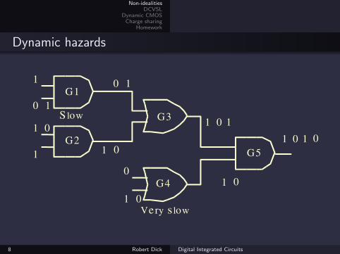
Dynamic hazards
G1
G2
G3
G5
G4
0 1
1
1 0
1
0 1
1 0
1 0 1
1 00
1 0
1 0 1 0
S low
Ve ry s low
8 Robert Dick Digital Integrated Circuits
Non-idealitiesDCVSL
Dynamic CMOSCharge sharing
Homework
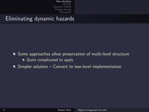
Eliminating dynamic hazards
Some approaches allow preservation of multi-level structure
Quite complicated to apply
Simpler solution – Convert to two-level implementation
9 Robert Dick Digital Integrated Circuits
Non-idealitiesDCVSL
Dynamic CMOSCharge sharing
Homework
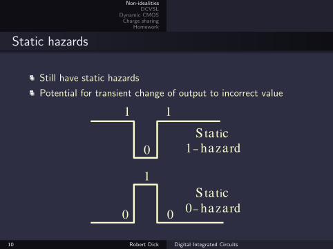
Static hazards
Still have static hazards
Potential for transient change of output to incorrect value
S ta tic
0− haza rd
S ta tic
1− haza rd
1 1
0
1
0 0
10 Robert Dick Digital Integrated Circuits
Non-idealitiesDCVSL
Dynamic CMOSCharge sharing
Homework
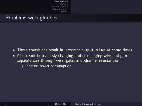
Problems with glitches
These transitions result in incorrect output values at some times
Also result in uselessly charging and discharging wire and gatecapacitances through wire, gate, and channel resistances
Increase power consumption
11 Robert Dick Digital Integrated Circuits
Non-idealitiesDCVSL
Dynamic CMOSCharge sharing
Homework
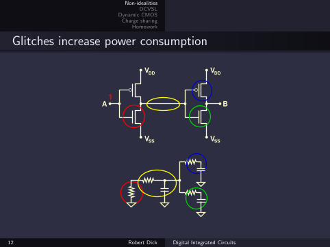
Glitches increase power consumption
VDD
VDD
VSSVSS
BA1
12 Robert Dick Digital Integrated Circuits
Non-idealitiesDCVSL
Dynamic CMOSCharge sharing
Homework
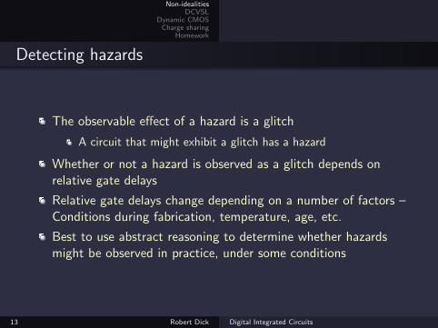
Detecting hazards
The observable effect of a hazard is a glitch
A circuit that might exhibit a glitch has a hazard
Whether or not a hazard is observed as a glitch depends onrelative gate delays
Relative gate delays change depending on a number of factors –Conditions during fabrication, temperature, age, etc.
Best to use abstract reasoning to determine whether hazardsmight be observed in practice, under some conditions
13 Robert Dick Digital Integrated Circuits
Non-idealitiesDCVSL
Dynamic CMOSCharge sharing
Homework
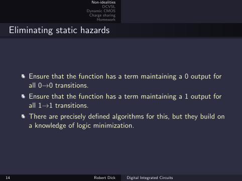
Eliminating static hazards
Ensure that the function has a term maintaining a 0 output forall 0→0 transitions.
Ensure that the function has a term maintaining a 1 output forall 1→1 transitions.
There are precisely defined algorithms for this, but they build ona knowledge of logic minimization.
14 Robert Dick Digital Integrated Circuits
Non-idealitiesDCVSL
Dynamic CMOSCharge sharing
Homework
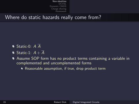
Where do static hazards really come from?
Static-0: A A
Static-1: A + A
Assume SOP form has no product terms containing a variable incomplemented and uncomplemented forms
Reasonable assumption, if true, drop product term
15 Robert Dick Digital Integrated Circuits
Non-idealitiesDCVSL
Dynamic CMOSCharge sharing
Homework
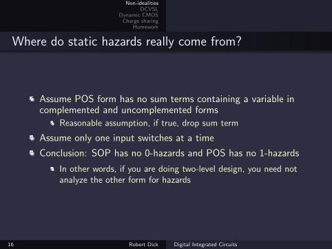
Where do static hazards really come from?
Assume POS form has no sum terms containing a variable incomplemented and uncomplemented forms
Reasonable assumption, if true, drop sum term
Assume only one input switches at a time
Conclusion: SOP has no 0-hazards and POS has no 1-hazards
In other words, if you are doing two-level design, you need notanalyze the other form for hazards
16 Robert Dick Digital Integrated Circuits
Non-idealitiesDCVSL
Dynamic CMOSCharge sharing
Homework
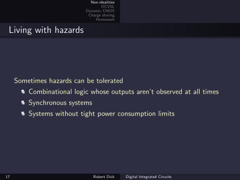
Living with hazards
Sometimes hazards can be tolerated
Combinational logic whose outputs aren’t observed at all times
Synchronous systems
Systems without tight power consumption limits
17 Robert Dick Digital Integrated Circuits
Non-idealitiesDCVSL
Dynamic CMOSCharge sharing
Homework
Lecture plan
1. Non-idealities
2. DCVSL
3. Dynamic CMOS
4. Charge sharing
5. Homework
18 Robert Dick Digital Integrated Circuits
Non-idealitiesDCVSL
Dynamic CMOSCharge sharing
Homework
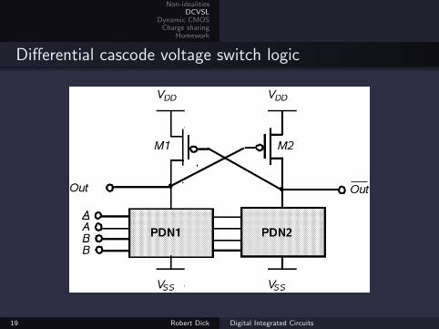
Differential cascode voltage switch logic
19 Robert Dick Digital Integrated Circuits
Non-idealitiesDCVSL
Dynamic CMOSCharge sharing
Homework
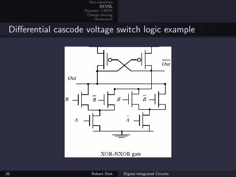
Differential cascode voltage switch logic example
20 Robert Dick Digital Integrated Circuits
Non-idealitiesDCVSL
Dynamic CMOSCharge sharing
Homework
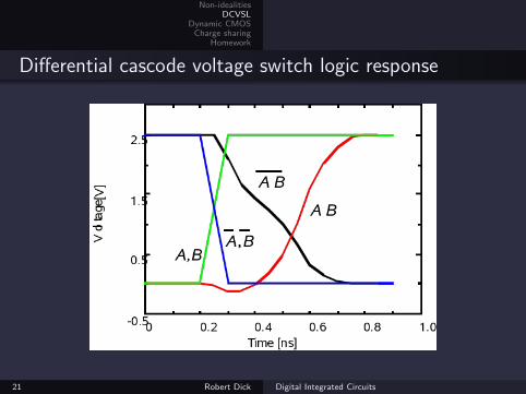
Differential cascode voltage switch logic response
21 Robert Dick Digital Integrated Circuits
Non-idealitiesDCVSL
Dynamic CMOSCharge sharing
Homework
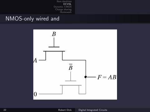
NMOS-only wired and
22 Robert Dick Digital Integrated Circuits
Non-idealitiesDCVSL
Dynamic CMOSCharge sharing
Homework
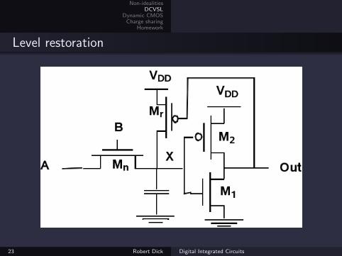
Level restoration
23 Robert Dick Digital Integrated Circuits
Non-idealitiesDCVSL
Dynamic CMOSCharge sharing
Homework
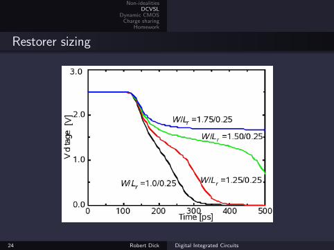
Restorer sizing
24 Robert Dick Digital Integrated Circuits
Non-idealitiesDCVSL
Dynamic CMOSCharge sharing
Homework
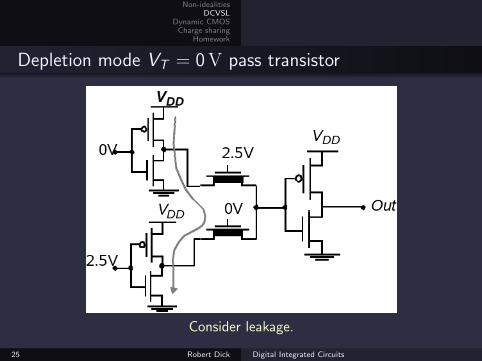
Depletion mode VT = 0V pass transistor
Consider leakage.
25 Robert Dick Digital Integrated Circuits
Non-idealitiesDCVSL
Dynamic CMOSCharge sharing
Homework
Lecture plan
1. Non-idealities
2. DCVSL
3. Dynamic CMOS
4. Charge sharing
5. Homework
26 Robert Dick Digital Integrated Circuits
Non-idealitiesDCVSL
Dynamic CMOSCharge sharing
Homework
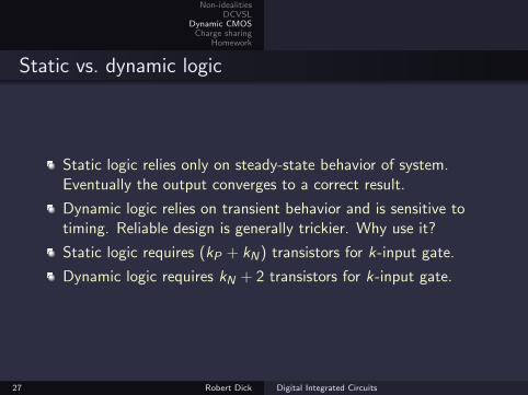
Static vs. dynamic logic
Static logic relies only on steady-state behavior of system.Eventually the output converges to a correct result.
Dynamic logic relies on transient behavior and is sensitive totiming. Reliable design is generally trickier. Why use it?
Static logic requires (kP + kN) transistors for k-input gate.
Dynamic logic requires kN + 2 transistors for k-input gate.
27 Robert Dick Digital Integrated Circuits
Non-idealitiesDCVSL
Dynamic CMOSCharge sharing
Homework
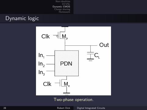
Dynamic logic
Two-phase operation.
28 Robert Dick Digital Integrated Circuits
Non-idealitiesDCVSL
Dynamic CMOSCharge sharing
Homework
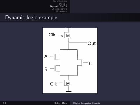
Dynamic logic example
29 Robert Dick Digital Integrated Circuits
Non-idealitiesDCVSL
Dynamic CMOSCharge sharing
Homework
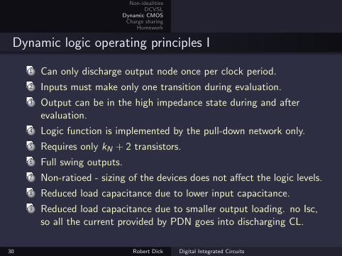
Dynamic logic operating principles I
1 Can only discharge output node once per clock period.
2 Inputs must make only one transition during evaluation.
3 Output can be in the high impedance state during and afterevaluation.
4 Logic function is implemented by the pull-down network only.
5 Requires only kN + 2 transistors.
6 Full swing outputs.
7 Non-ratioed - sizing of the devices does not affect the logic levels.
8 Reduced load capacitance due to lower input capacitance.
9 Reduced load capacitance due to smaller output loading. no Isc,so all the current provided by PDN goes into discharging CL.
30 Robert Dick Digital Integrated Circuits
Non-idealitiesDCVSL
Dynamic CMOSCharge sharing
Homework
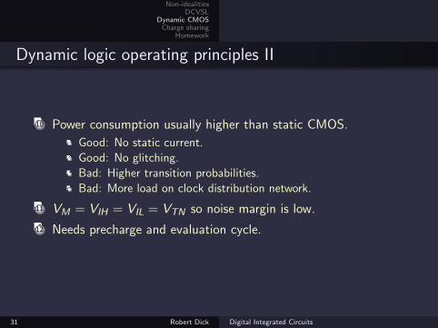
Dynamic logic operating principles II
10 Power consumption usually higher than static CMOS.
Good: No static current.
Good: No glitching.
Bad: Higher transition probabilities.
Bad: More load on clock distribution network.
11 VM = VIH = VIL = VTN so noise margin is low.
12 Needs precharge and evaluation cycle.
31 Robert Dick Digital Integrated Circuits

Non-idealitiesDCVSL
Dynamic CMOSCharge sharing
Homework
Upcoming topics
Example problems on recently covered material.
Latches and flip-flops.
32 Robert Dick Digital Integrated Circuits
Non-idealitiesDCVSL
Dynamic CMOSCharge sharing
Homework
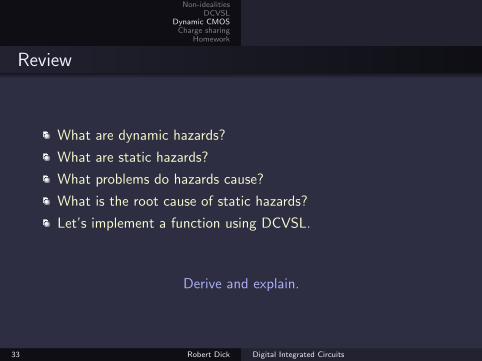
Review
What are dynamic hazards?
What are static hazards?
What problems do hazards cause?
What is the root cause of static hazards?
Let’s implement a function using DCVSL.
Derive and explain.
33 Robert Dick Digital Integrated Circuits
Non-idealitiesDCVSL
Dynamic CMOSCharge sharing
Homework
Lecture plan
1. Non-idealities
2. DCVSL
3. Dynamic CMOS
4. Charge sharing
5. Homework
34 Robert Dick Digital Integrated Circuits
Non-idealitiesDCVSL
Dynamic CMOSCharge sharing
Homework
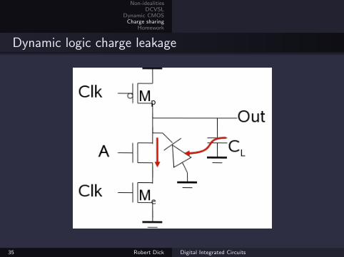
Dynamic logic charge leakage
35 Robert Dick Digital Integrated Circuits
Non-idealitiesDCVSL
Dynamic CMOSCharge sharing
Homework
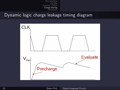
Dynamic logic charge leakage timing diagram
36 Robert Dick Digital Integrated Circuits
Non-idealitiesDCVSL
Dynamic CMOSCharge sharing
Homework
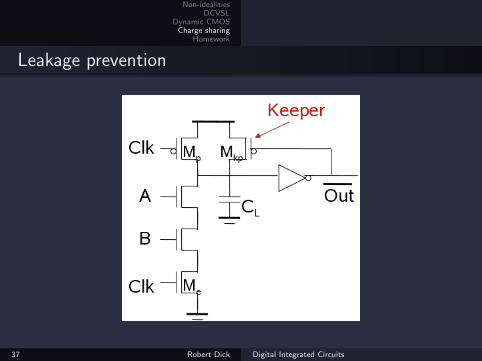
Leakage prevention
37 Robert Dick Digital Integrated Circuits
Non-idealitiesDCVSL
Dynamic CMOSCharge sharing
Homework
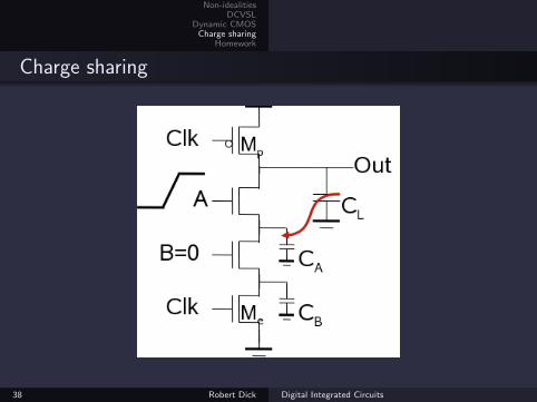
Charge sharing
38 Robert Dick Digital Integrated Circuits
Non-idealitiesDCVSL
Dynamic CMOSCharge sharing
Homework
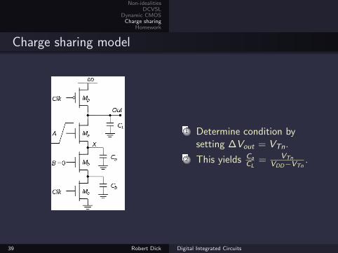
Charge sharing model
1 Determine condition bysetting ∆Vout = VTn.
2 This yields CaCL
= VTnVDD−VTn
.
39 Robert Dick Digital Integrated Circuits
Non-idealitiesDCVSL
Dynamic CMOSCharge sharing
Homework
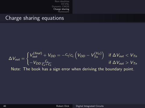
Charge sharing equations
∆Vout =
{V
(final)out + VDD = −Ca/CL
(VDD − V
(VX )Tn
)if ∆Vout < VTn
−VDDCa
Ca+CLif ∆Vout > VTn
Note: The book has a sign error when deriving the boundary point.
40 Robert Dick Digital Integrated Circuits
Non-idealitiesDCVSL
Dynamic CMOSCharge sharing
Homework
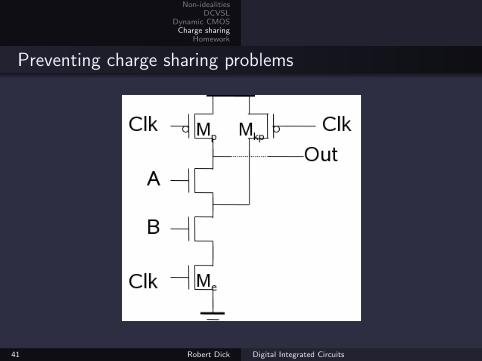
Preventing charge sharing problems
41 Robert Dick Digital Integrated Circuits
Non-idealitiesDCVSL
Dynamic CMOSCharge sharing
Homework
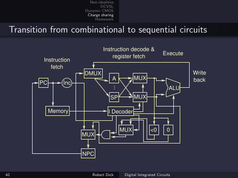
Transition from combinational to sequential circuits
Inc
Instruction
fetch
A MUX
MUX
NPC
<0 0MUX
Instruction decode &
register fetch
Write
back
SP
PC
Memory..
.
ALU
DMUX
Execute
I Decoder
MUX
42 Robert Dick Digital Integrated Circuits

Non-idealitiesDCVSL
Dynamic CMOSCharge sharing
Homework
Upcoming topics
Sense amplifiers.
A more formal approach to gate sizing.
43 Robert Dick Digital Integrated Circuits
Non-idealitiesDCVSL
Dynamic CMOSCharge sharing
Homework
Lecture plan
1. Non-idealities
2. DCVSL
3. Dynamic CMOS
4. Charge sharing
5. Homework
44 Robert Dick Digital Integrated Circuits
Non-idealitiesDCVSL
Dynamic CMOSCharge sharing
Homework
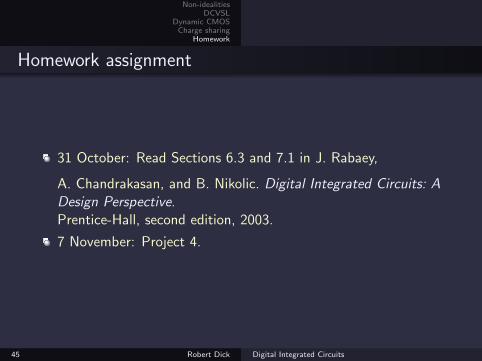
Homework assignment
31 October: Read Sections 6.3 and 7.1 in J. Rabaey,
A. Chandrakasan, and B. Nikolic. Digital Integrated Circuits: ADesign Perspective.Prentice-Hall, second edition, 2003.
7 November: Project 4.
45 Robert Dick Digital Integrated Circuits