4 manual de instalación, operación y mantenimiento.pdf
TRANSCRIPT

8/10/2019 4 Manual de Instalación, Operación y Mantenimiento.pdf
http://slidepdf.com/reader/full/4-manual-de-instalacion-operacion-y-mantenimientopdf 1/14
INSTALLATION, OPERATION ANDMAINTENANCE MANUAL
30119-03 Rev. 5.0April, 2014
ELECTROMAGNETIC
FLOWMETERS

8/10/2019 4 Manual de Instalación, Operación y Mantenimiento.pdf
http://slidepdf.com/reader/full/4-manual-de-instalacion-operacion-y-mantenimientopdf 2/14
8/10/2019 4 Manual de Instalación, Operación y Mantenimiento.pdf
http://slidepdf.com/reader/full/4-manual-de-instalacion-operacion-y-mantenimientopdf 3/14
iii
Copyright © 1997-2014 McCrometer, Inc. All printed material should not be changed or altered without permissionof McCrometer. Any published technical data and instructions are subject to change without notice. Contact yourMcCrometer representative for current technical data and instructions.
www.mccrometer.com3255 WEST STETSON AVENUE • HEMET, CALIFORNIA 92545 USATEL: 951-652-6811 • 800-220-2279 • FAX: 951-652-3078 Printed In The U.S.A. Lit. # 30119-03 Rev. 5.0/04-14
Section Page
1. INTRODUCTION .................................................................................................................................................................................. 1.1 Description .................................................................................................................................................................................... 1.2 Uncrating ....................................................................................................................................................................................... 1.3 Parts List With Remote Mount Converter ..................................................................................................................................2 1.4 Serial Numbers ..............................................................................................................................................................................
2. SENSOR INSTALLATION ................................................................................................................................................................... 2.1 Installation Considerations ............................................................................................................................................................ 2.1.1 Grounding And Electrical Interference ..........................................................................................................................3 2.1.2 Lines With Cathodic Protection .........................................................................................................................................3 2.1.3 Fluid Conductivity ............................................................................................................................................................. 2.1.4 Meter Mounted Converter Location ..............................................................................................................................4 2.1.5 Remote Mount .................................................................................................................................................................... 2.1.6 Grounding Ring And Gaskets ............................................................................................................................................4 2.1.7 Converter/transmitter Connections ................................................................................................................................4 2.2 Positioning The Sensor ..................................................................................................................................................................
2.2.1 Pipe Diameters .................................................................................................................................................................... 2.2.2 Flow Direction .................................................................................................................................................................... 2.2.3 Sensor Orientation...............................................................................................................................................................
3. DIMENSIONS .......................................................................................................................................................................................
4. SPECIFICATIONS .................................................................................................................................................................................
5 RETURNING A UNIT FOR REPAIR ....................................................................................................................................................
WARRANTY ..............................................................................................................................................................................................
TABLE OF CONTENTS
8/10/2019 4 Manual de Instalación, Operación y Mantenimiento.pdf
http://slidepdf.com/reader/full/4-manual-de-instalacion-operacion-y-mantenimientopdf 4/14
1
• Installation and maintenance must only be carried out by suitably trained personnel.• HAZARDOUS AREA DESIGNATION ON THE EQUIPMENT LABEL MUST BE SUITABLE
FOR THE INTENDED DUTY AND LOCATION.• All relevant sections in this O & M Manual must be read before selecting a location.• Safety requirements of this equipment, any associated equipment and the local
environment must be taken into consideration.• The installation and use of this equipment must be in accordance with relevant national
and local standards.
Warning:
!
1. INTRODUCTION
1.1 Description
Ultra Mag meters are available with integral or remote mount converters. Standard display features includeforward, reverse and net ow totalizers, ow rate, alarm monitoring, and automatic self diagnostics to ensure
integrity. All data and values are in selectable units of measurement. System compatibility is assured with achoice of current, pulse and serial data. Please refer to the converter manual provided with your meter.
Ultra Mag operating parameters are set via the electronics keypad. The software features multilevel passwordprotection capability to prevent inadvertent program or setting changes. Data is stored in nonvolatile memory.
The anged end tube design permits use in a wide range of applications. The fabricated tube is stainless steelwith steel or stainless steel anges and incorporates the UltraLiner, an NSF approved fusion-bonded epoxy liner.
1.2 Uncrating
The shipping crate contains the following items:
Electromagnetic Meter Assembly with grounding wire attached Converter Cable (attached to meter) Signal Converter Grounding Ring (optional for 4”-12” models) Ground Wires (2) Installation, Operation and Maintenance Manuals for both the sensor and converter
When uncrating the Ultra Mag, any damage due to rough or improper handling should be reported to thetransportation rm and McCrometer. If for any reason it is determined that the unit or parts of the unit should bereturned to the factory, please contact McCrometer for clearance prior to shipment. Each unit must be properlycrated to prevent any further damage. The factory assumes no responsibility for equipment damaged in returnshipment due to improper packaging.
8/10/2019 4 Manual de Instalación, Operación y Mantenimiento.pdf
http://slidepdf.com/reader/full/4-manual-de-instalacion-operacion-y-mantenimientopdf 5/14
2
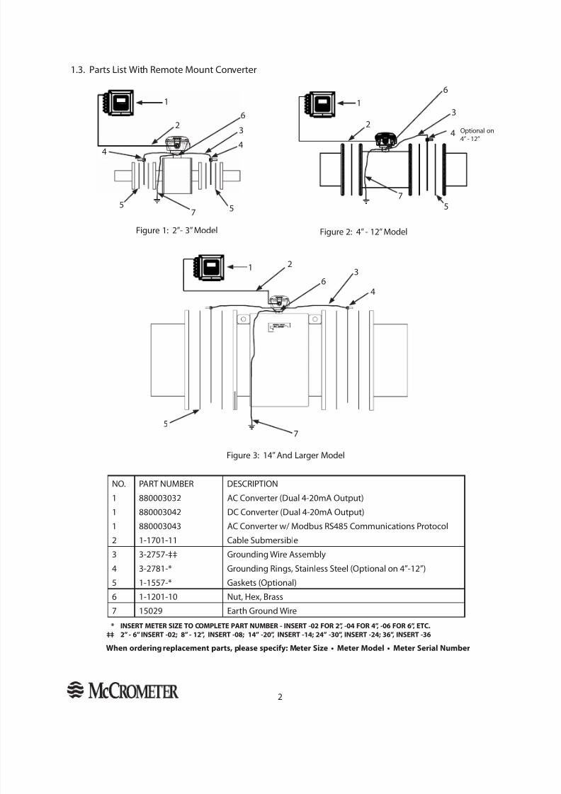
1.3. Parts List With Remote Mount Converter
* INSERT METER SIZE TO COMPLETE PART NUMBER - INSERT -02 FOR 2”, -04 FOR 4”, -06 FOR 6”, ETC. ‡‡ 2” - 6” INSERT -02; 8” - 12”, INSERT -08; 14” -20”, INSERT -14; 24” -30”, INSERT -24; 36”, INSERT -36
When ordering replacement parts, please specify: Meter Size • Meter Model • Meter Serial Number
Figure 3: 14” And Larger Model
NO. PART NUMBER DESCRIPTION
1 880003032 AC Converter (Dual 4-20mA Output)
1 880003042 DC Converter (Dual 4-20mA Output)
1 880003043 AC Converter w/ Modbus RS485 Communications Protocol
2 1-1701-11 Cable Submersible
3 3-2757-‡‡ Grounding Wire Assembly4 3-2781-* Grounding Rings, Stainless Steel (Optional on 4”-12”)
5 1-1557-* Gaskets (Optional)
6 1-1201-10 Nut, Hex, Brass
7 15029 Earth Ground Wire
Figure 1: 2”- 3” Model Figure 2: 4” - 12” Model
5
1
2
7
4
6
Optional on
4” - 12”
32
4
3
55
61
7
4
1 23
4
5
6
7
8/10/2019 4 Manual de Instalación, Operación y Mantenimiento.pdf
http://slidepdf.com/reader/full/4-manual-de-instalacion-operacion-y-mantenimientopdf 6/14
3
2. SENSOR INSTALLATION
2.1 Installation Considerations
2.1.1 Grounding And Electrical Interference
The sensor body must have electrical contact with the media. This is achieved via a grounding ring or groundingbutton. NOTE: The grounding ring is optional only on 4” through 12” models.
Always ensure that the converter and the sensor are grounded (earthed) correctly. The grounding of the sensorand converter ensures that the equipment and liquid have an equal potential. For most installations the qualityof grounding by the provided cabling assures the sensor is properly grounded and additional grounding of thesensor is not required. However, in instances where this is not the case, i.e. the equipment and uid do not havean equal potential, such as where the installation location and/or media is subjected to electrical interference,additional grounding steps may be required. Consult an electrician experienced with instrumentationinstallations to determine if electrical interference is present. For further information on installationenvironments and sensor grounding, please contact McCrometer Technical Support .
2.1.2 Lines With Cathodic Protection
On meters installed on a line with cathodic protection it may be necessary to insulate the meter from the line.Consult your cathodic protection vendor for instructions.
2.1.3 Fluid Conductivity
The uid to be measured must have a minimum conductivity of 5μS/cm for an electromagnetic ow meterto operate. Systems with such low conductivity require that the system is well grounded with no electrical
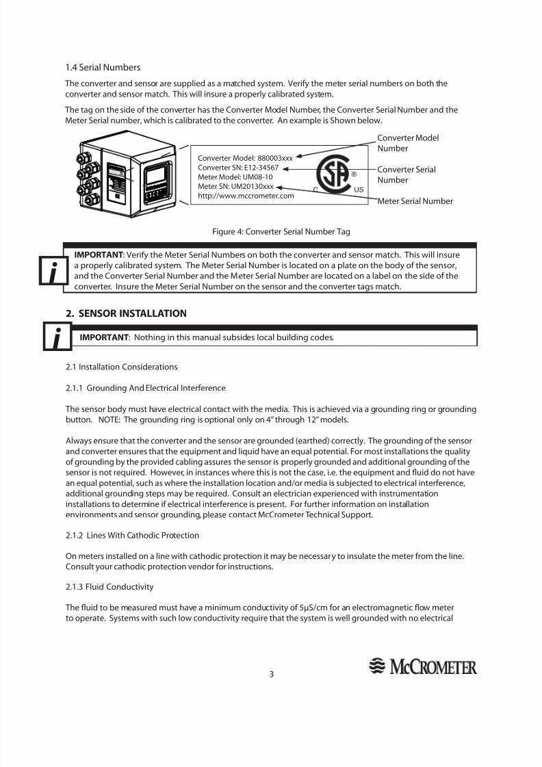
IMPORTANT : Verify the Meter Serial Numbers on both the converter and sensor match. This will insure
a properly calibrated system. The Meter Serial Number is located on a plate on the body of the sensor,and the Converter Serial Number and the Meter Serial Number are located on a label on the side of theconverter. Insure the Meter Serial Number on the sensor and the converter tags match.i
1.4 Serial Numbers
The converter and sensor are supplied as a matched system. Verify the meter serial numbers on both theconverter and sensor match. This will insure a properly calibrated system.
The tag on the side of the converter has the Converter Model Number, the Converter Serial Number and theMeter Serial number, which is calibrated to the converter. An example is Shown below.
Figure 4: Converter Serial Number Tag
Converter ModelNumber
Converter SerialNumber
Meter Serial Number
Converter Model: 880003xxxConverter SN: E12-34567Meter Model: UM08-10Meter SN: UM20130xxxhttp://www.mccrometer.com
USC
®Conve rt e r Mode l: 880003xxx
Conve rt e r SN: E12-34567Me te r Mode l: UM08-10Me te r SN:UM20130xxxh t tp : // ww w.m cc rom e ter.c om
U S
C®
IMPORTANT : Nothing in this manual subsides local building codes.i
8/10/2019 4 Manual de Instalación, Operación y Mantenimiento.pdf
http://slidepdf.com/reader/full/4-manual-de-instalacion-operacion-y-mantenimientopdf 7/14
4
interference. Also, In low conductivity uids (less than 50 μS/cm) long cable lengths may affect ow meter’sability to read the ow signal.
To eliminate rapid changes in uid conductivity, it is recommended that all blending and chemical injectingbe done downstream of the meter to avoid possible measurement error and/or issues. If blending or chemicalinjecting is performed upstream of the meter, is should be done upstream of the meter early enough so the owmedia is thoroughly mixed prior to entering the measurement area.
2.1.4 Meter Mounted Converter Location
Adjoining pipe must be adequately supported, and the area around the sensor should provide sufficientdrainage to prevent ooding the converter or conduits.
The location chosen should provide room to read the display and be free from harsh electrical noise fromadjacent equipment, cables, R.F.I., or E.M.I. The signal converter should not be subjected to intense, prolongedsunlight and/or vibrations. Unit should also be protected from heat.
2.1.5 Remote Mount
The signal converter may be installed in a desired location provided that free access is available to allow thedisplay to be viewed as required. The unit can be either wall mounted or panel mounted with masonry xingsor nuts and bolts respectively via the xing holes provided. The maximum distance between the meter and theconverter is 200 feet. For applications with extended lengths, consult factory.
2.1.6 Grounding Ring And Gaskets
The grounding rings and gaskets must be used to ensure a positive seal at the anges, and to ensure uid isproperly grounded to sensor. The grounding ring is optional on the 4” through 12” models as these modelsutilize grounding buttons.
2.1.7 Converter/transmitter Connections
Connections to the sensor must be made with cable supplied by McCrometer specically for that purpose. Donot substitute the supplied cable with other types of cable, even for short runs. For repairs or added lengths ofcable, the entire cable between the sensor and the converter must be replaced. (Consult factory for replacementcable.)
2.2 Positioning The Sensor
2.2.1 Pipe Diameters
For proper accuracies any 90 or 45 degree elbows, valves, partially opened valves etc. should be placed notcloser than ve pipe diameters upstream and two pipe diameters downstream.
2.2.2 Flow Direction
The ow of the medium should correspond to the direction shown by the arrow on the sensor.
2. SENSOR INSTALLATION - Cont.
1: Gaskets must be used on either side of the grounding ring to provide a proper seal on the anges.One gasket is used on anges without a grounding ring.
2: Rings & gaskets must align concentrically with the pipe so they do not obstruct or affect ow throughthe tube.
Information For All Installations
8/10/2019 4 Manual de Instalación, Operación y Mantenimiento.pdf
http://slidepdf.com/reader/full/4-manual-de-instalacion-operacion-y-mantenimientopdf 8/14
5
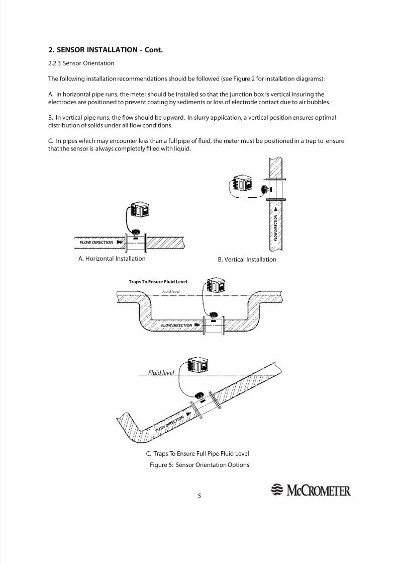
C. Traps To Ensure Full Pipe Fluid Level
A. Horizontal Installation
Figure 5: Sensor Orientation Options
B. Vertical Installation
2. SENSOR INSTALLATION - Cont.
FLOW DIRECTIONFLOW DIRECTION
Traps To Ensure Fluid Level
Fluid Level
FLOW DIRECTIONFLOW DIRECTION
Fluid level
F L O W D I R E C T I O N
F L O W D I R E C T I O N
Fluid Level
F L O W D I R
E C T I O N
Fluid level
F L O W D I R
E C T I O N
2.2.3 Sensor Orientation
The following installation recommendations should be followed (see Figure 2 for installation diagrams):
A. In horizontal pipe runs, the meter should be installed so that the junction box is vertical insuring theelectrodes are positioned to prevent coating by sediments or loss of electrode contact due to air bubbles.
B. In vertical pipe runs, the ow should be upward. In slurry application, a vertical position ensures optimaldistribution of solids under all ow conditions.
C. In pipes which may encounter less than a full pipe of uid, the meter must be positioned in a trap to ensurethat the sensor is always completely lled with liquid.

8/10/2019 4 Manual de Instalación, Operación y Mantenimiento.pdf
http://slidepdf.com/reader/full/4-manual-de-instalacion-operacion-y-mantenimientopdf 9/14
6
Figure 11: 2" and 3" Models Body Style
Figure 13: 14+" Models Body Style
3. DIMENSIONS
Figure 12: 4" to 12" Models Body Style
End ViewSide View
End ViewSide View
C
A
E
DC
B
A
E
Side ViewEnd View
**Grounding Rings are 0.125" thick.
E
C
BA
D
8/10/2019 4 Manual de Instalación, Operación y Mantenimiento.pdf
http://slidepdf.com/reader/full/4-manual-de-instalacion-operacion-y-mantenimientopdf 10/14
7
3. DIMENSIONS - Cont.
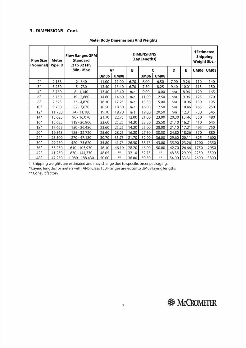
Meter Body Dimenesions And Weights
† Shipping weights are estimated and may change due to specic order packaging.* Laying lengths for meters with ANSI Class 150 Flanges are equal to UM08 laying lengths** Consult factory
Pipe Size(Nominal)
MeterPipe ID
Flow Ranges GPM
Standard.2 to 32 FPSMin - Max
DIMENSIONS
(Lay Lengths)
†EstimatedShipping
Weight (lbs.)
A* B C D E UM06 UM08UM06 UM08 UM06 UM08
2" 2.156 2 - 340 11.00 11.00 6.70 6.00 6.50 7.90 9.26 110 1403" 3.250 5 - 730 13.40 13.40 6.70 7.50 8.25 9.40 10.01 115 1504" 3.750 8 - 1,140 13.40 13.40 n/a 9.00 10.00 n/a 8.06 120 1656" 5.750 19 - 2,660 14.60 14.60 n/a 11.00 12.50 n/a 9.06 125 1708" 7.375 33 - 4,870 16.10 17.25 n/a 13.50 15.00 n/a 10.06 130 195
10" 9.750 52 - 7,670 18.50 18.50 n/a 16.00 17.50 n/a 10.46 165 25012" 11.750 74 - 11,180 19.70 19.70 n/a 19.00 20.50 n/a 12.31 230 34514" 13.625 90 - 16,070 21.70 22.75 12.00 21.00 23.00 20.30 15..46 350 480
16" 15.625 118 - 20,900 23.60 25.25 14.20 23.50 25.50 21.10 16.21 410 64518" 17.625 150 - 26,480 23.60 25.25 14.20 25.00 28.00 21.10 17.21 495 75020" 19.563 185 - 32,720 25.60 28.25 16.20 27.50 30.50 24.80 18.26 570 88024" 23.500 270 - 47,180 30.70 35.75 21.70 32.00 36.00 29.60 20.11 825 160030" 29.250 420 - 73,620 35.80 41.75 26.50 38.75 43.00 35.90 23.26 1200 235036" 35.250 610 - 105,930 46.10 46.10 28.20 46.00 50.00 42.70 26.66 1750 295042" 41.250 830 - 144,370 48.05 ** 32.10 52.75 ** 48.35 29.99 2250 350048" 47.250 1,080 - 188,430 50.00 ** 36.00 59.50 ** 54.00 33.31 2600 3800
8/10/2019 4 Manual de Instalación, Operación y Mantenimiento.pdf
http://slidepdf.com/reader/full/4-manual-de-instalacion-operacion-y-mantenimientopdf 11/14
8
Accuracy: (under reference conditions) : ±.5% of actual ow from .2 to 32 FPS
Accuracy Tests: 3-point wet ow calibration of every complete ow tube with its signal converter. If desired, thetests can be witnessed by the customer. The McCrometer test facilities are traceable to the National Institute ofStandards & Technology. The test facility uncertainty relative to ow is ±.15%
Repeatability: ±0.05% or ±0.0008ft/s (±0.25mm/s), whichever is greater
Bi-directional Flow: Forward and reverse ow indication and forward and reverse net totalization are standardwith all meters
Head Loss: None. No obstruction in line and no moving parts.
Pressure Range: 150 PSI maximum working pressure (UM06)300 PSI maximum working pressure (UM08)
Sensor Temperature Range:
Operating: -10 to 77°C (14 to 170°F)Storage: -15 to 77°C (5 to 170° F)
Conductivity: Liquids and slurries having a conductivity of not less than 5μS/cm (5μmho/cm). For slurryapplications please contact the factory for special converter programming.
Liner: UltraLiner NSF approved, fusion bonded epoxy
Electrodes: Stainless steel (Hastelloy® optional)
Sensor Cable: McCrometer supplied submersible standard
Converter/sensor Separation: ≤ 200 feet; for longer lengths consult factory
Calibration: Wet ow calibrated in McCrometer ow lab traceable to the National Institute of Standards and Technology.
Sensor Cable Connection: Provided wired.
Ratings: Metering tube with remote converter is NEMA 6P/IP68
Certi cations:Safety: Listed by CSA to 61010-1: Certied by CSA to UL 61010-1 and CSA C22.2 No.61010-1-04
Options:• DC Powered converter (10-35 VDC, 21W)•
Meter mounted converter• Extended warranty• Hastelloy ® electrodes• ANSI or DIN anges• Special lay lengths, including ISO standard lay lengths• Converter sun shield• Modbus Protocol RS485
4. SPECIFICATIONS
8/10/2019 4 Manual de Instalación, Operación y Mantenimiento.pdf
http://slidepdf.com/reader/full/4-manual-de-instalacion-operacion-y-mantenimientopdf 12/14
9
5. Returning A Unit For Repair
13.3 Returning A Unit For Repair
If the unit needs to be returned to the factory for repair, please do the following:
• Prior to calling for a return authorization number, determine the model number, serial number, and reasonfor return.
• Call the McCrometer Customer Service Department and ask for a Return Authorization (RA) number.
• Ship the meter in the original packaging, if possible. Do not ship manuals, power cords, or other parts withyour unit unless required for repair.
• Please make sure the meter is clean and free from foreign debris prior to shipping.
• Write the RA number on the outside of the shipping box. All return shipments should be insured.
• Address all shipments to:
McCrometer, Inc. RMA #
3255 W. Stetson Avenue Hemet, CA 92545

8/10/2019 4 Manual de Instalación, Operación y Mantenimiento.pdf
http://slidepdf.com/reader/full/4-manual-de-instalacion-operacion-y-mantenimientopdf 13/14
10
WARRANTY
This Warranty shall apply to and be limited to the original purchaser consumer of any McCrometer product. Metersor instruments defective because of faulty material or workmanship will be repaired or replaced, at the option ofMcCrometer, free of charge, FOB the factory in Hemet, California, within a period of two (2) years from the date ofdelivery.
Repairs or modications by others than McCrometer or their authorized representatives shall render this Warrantynull and void in the event that factory examination reveals that such repair or modication was detrimental to themeter or instrument. Any deviations from the factory calibration require notication in writing to McCrometer ofsuch recalibrations or this Warranty shall be voided.
In case of a claim under this Warranty, the claimant is instructed to contact McCrometer, 3255 W. Stetson Ave.,Hemet, California 92545, and to provide an identication or description of the meter or instrument, the date ofdelivery, and the nature of the problem.
The Warranty provided above is the only Warranty made by McCrometer with respect to its products or any partsthereof and is made expressly in lieu of any other warranties, by course of dealing, usages of trade or otherwise,expressed or implied, including but not limited to any implied warranties of tness for any particular purpose orof merchantability under the uniform commercial code. It is agreed this Warranty is in lieu of and buyer herebywaives all other warranties, guarantees or liabilities arising by law or otherwise. Seller shall not incur any otherobligations or liabilities or be liable to buyer, or any customer of buyer for any anticipated or lost prots, incidentalor consequential damages, or any other losses or expenses incurred by reason of the purchase, installation, repair,use or misuse by buyer or third parties of its products (including any parts repaired or replaced); and seller doesnot authorize any person to assume for seller any other liability in connection with the products or parts thereof. This Warranty cannot be extended, altered or varied except by a written instrument signed by seller and buyer.
This Warranty gives you specic legal rights, and you may also have other rights which vary from state to state.
McCrometer reserves the right to make improvements and repairs on product components which are beyond theWarranty period at the manufacturer’s option and expense, without obligation to renew the expired Warranty onthe components or on the entire unit. Due to the rapid advancement of meter design technology, McCrometerreserves the right to make improvements in design and material without prior notice to the trade.
All sales and all agreements in relation to sales shall be deemed made at the manufacturer’s place of business inHemet, California and any dispute arising from any sale or agreement shall be interpreted under the laws of theState of California.
8/10/2019 4 Manual de Instalación, Operación y Mantenimiento.pdf
http://slidepdf.com/reader/full/4-manual-de-instalacion-operacion-y-mantenimientopdf 14/14
OTHER McCROMETER PRODUCTS INCLUDE:
Propeller Flowmeters
Propeller Flowmeters
Magnetic Flowmeters
Differential Pressure Flowmeters
Magnetic Flowmeters
Magnetic Flowmeters
Magnetic Flowmeters
Magnetic Flowmeters
Wireless Monitoring Systems
Differential Pressure Flowmeters
Differential Pressure Flowmeters
FOR MORE INFORMATION CONTACT:
Copyright © 1997-2014 McCrometer, Inc. All printed material should not be changed or altered without permissionof McCrometer. Any published technical data and instructions are subject to change without notice. Contact yourMcCrometer representative for current technical data and instructions.
www.mccrometer.com3255 WEST STETSON AVENUE • HEMET, CALIFORNIA 92545 USATEL: 951-652-6811 • 800-220-2279 • FAX: 951-652-3078 Printed In The U.S.A. Lit. # 30119-03 Rev. 5.0/04-14