3phase.pdf number1
DESCRIPTION
3phase.pdf Number1TRANSCRIPT
EE 340Power Transformers
Y. Baghzouz
Spring 2012
Preliminary considerations
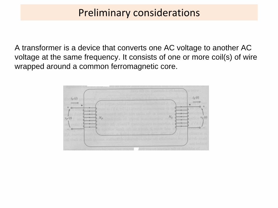
A transformer is a device that converts one AC voltage to another AC voltage at the same frequency. It consists of one or more coil(s) of wire wrapped around a common ferromagnetic core.
Common construction: Shell Form
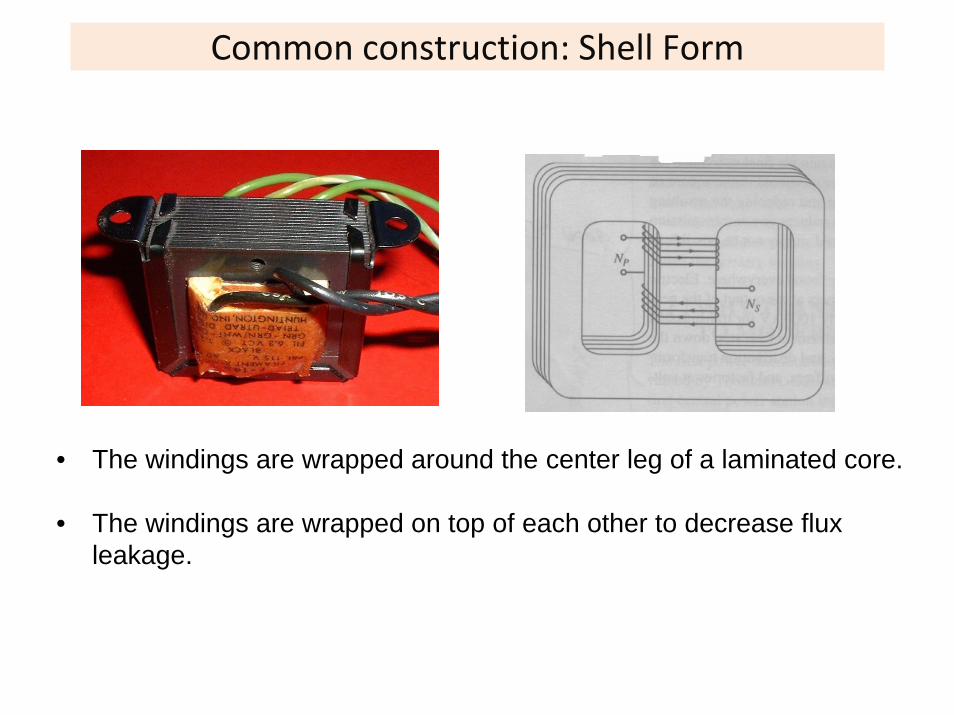
• The windings are wrapped around the center leg of a laminated core.
• The windings are wrapped on top of each other to decrease flux leakage.
Ideal transformer
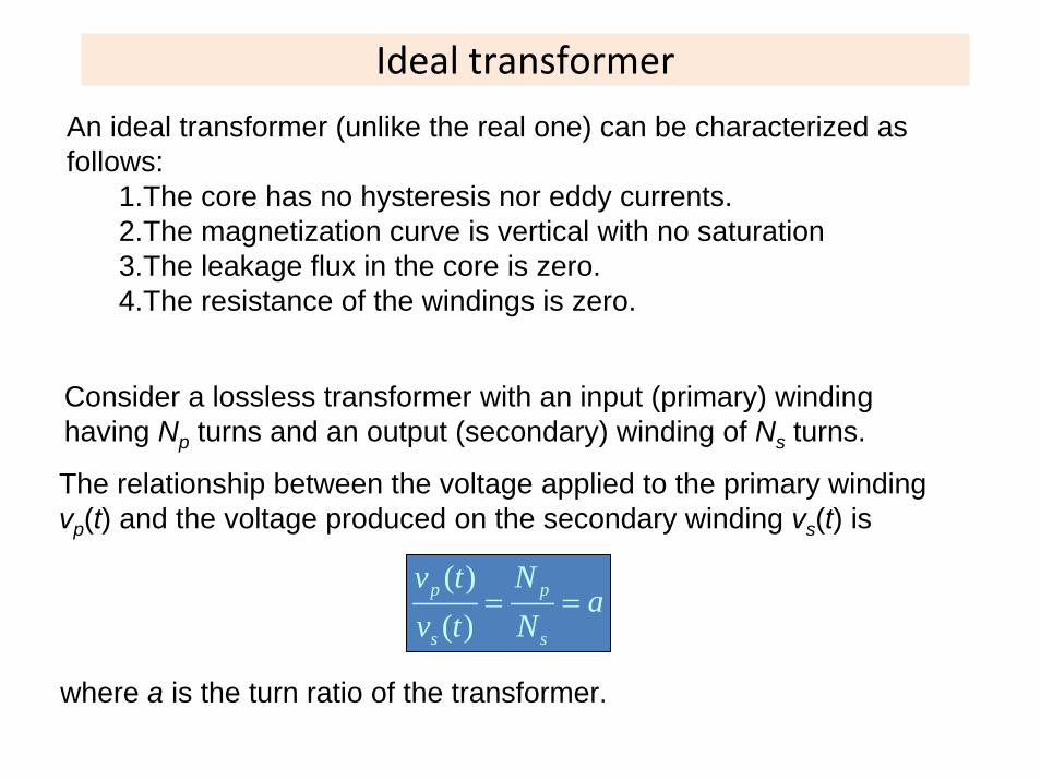
Consider a lossless transformer with an input (primary) winding having Np turns and an output (secondary) winding of Ns turns.
The relationship between the voltage applied to the primary winding vp(t) and the voltage produced on the secondary winding vs(t) is
( )( )
p p
s s
v t Na
v t N= =
where a is the turn ratio of the transformer.
An ideal transformer (unlike the real one) can be characterized as follows:
1.The core has no hysteresis nor eddy currents.2.The magnetization curve is vertical with no saturation3.The leakage flux in the core is zero.4.The resistance of the windings is zero.
Ideal transformer
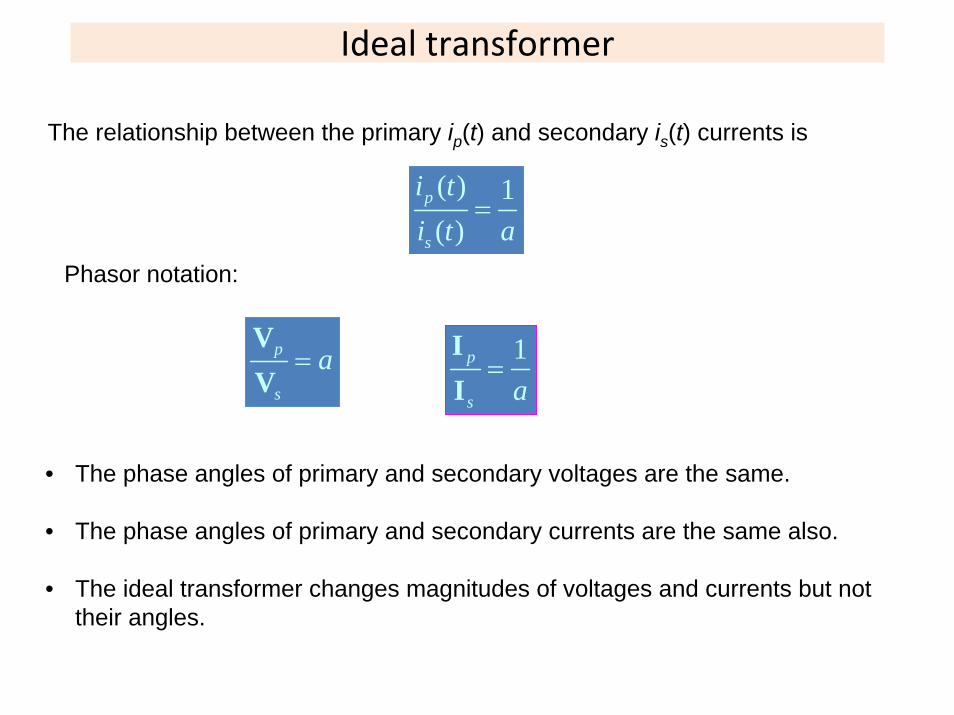
The relationship between the primary ip(t) and secondary is(t) currents is
( ) 1( )
p
s
i ti t a
=
Phasor notation:
p
s
a=VV
1p
s a=
II
• The phase angles of primary and secondary voltages are the same.
• The phase angles of primary and secondary currents are the same also.
• The ideal transformer changes magnitudes of voltages and currents but not their angles.
Ideal Transformer
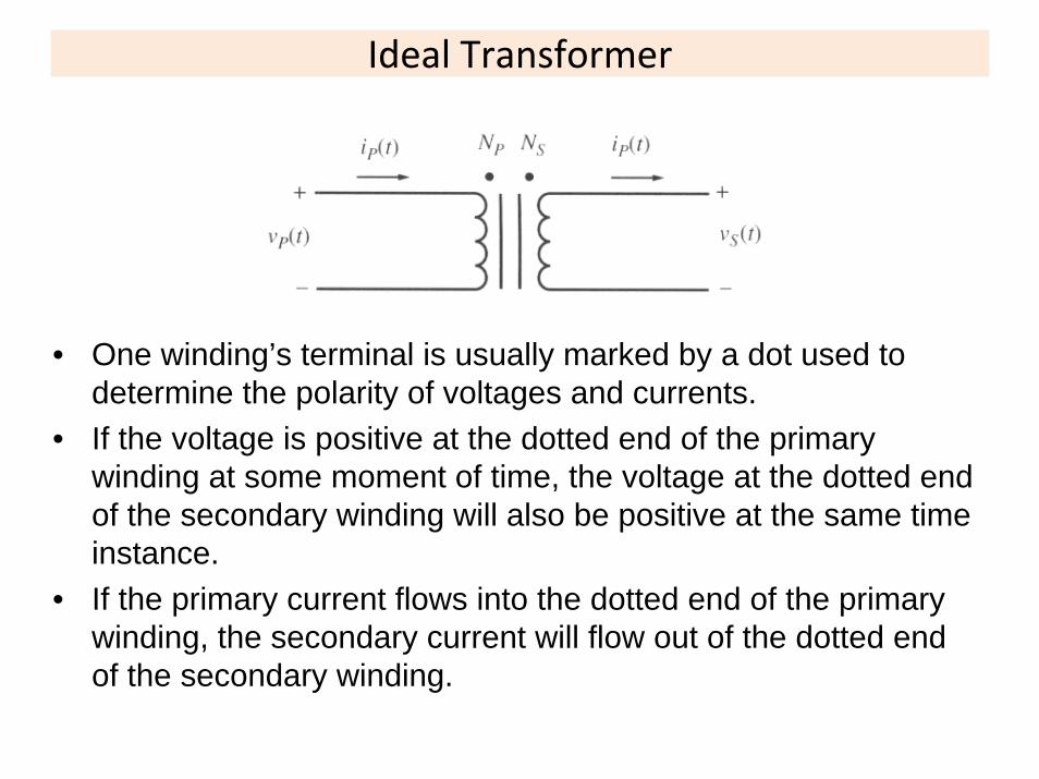
• One winding’s terminal is usually marked by a dot used to determine the polarity of voltages and currents.
• If the voltage is positive at the dotted end of the primary winding at some moment of time, the voltage at the dotted end of the secondary winding will also be positive at the same time instance.
• If the primary current flows into the dotted end of the primary winding, the secondary current will flow out of the dotted end of the secondary winding.

Power in an ideal transformer
Assuming that θp and θs are the angles between voltages and currents on the primary and secondary windings respectively, the power supplied to the transformer by the primary circuit is:
cosin p p pP V I θ=
The power supplied to the output circuit is
cosout s s sP V I θ=
Since ideal transformers do not affect angles between voltages and currents:
p sθ θ θ= =
Power in an ideal transformer
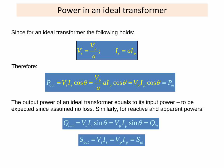
Since for an ideal transformer the following holds:
;ps s p
VV I aI
a= =
Therefore:
The output power of an ideal transformer equals to its input power – to be expected since assumed no loss. Similarly, for reactive and apparent powers:
sin sinout s s p p inQ V I V I Qθ θ= = =
out s s p p inS V I V I S= = =
cos cos cosout ip
s s p p p n
VV I aIP V I
aPθ θ θ= = ==
Impedance transformation
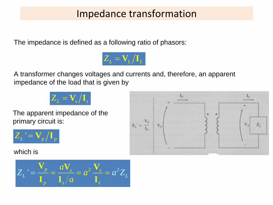
The impedance is defined as a following ratio of phasors:
L L LZ = V I
A transformer changes voltages and currents and, therefore, an apparent impedance of the load that is given by
L s sZ = V I
The apparent impedance of the primary circuit is:
'L p pZ = V I
which is
2 2' p s s
p s sL L
a aa
Z a Z= == =V V VI I I

Analysis of circuits containing ideal transformers: Example
Example 4.1: a) What is the voltage at the load? Calculate the transmission line losses? b) If a 1:10 step up transformer and a 10:1 step down transformer are placed at the generator and the load ends of the transmission line respectively, what are the new load voltage and the new transmission line losses?
a) Without transformers:
480 00.18 0
90.8 37
.24 4 3480 0
5.29 37.8
.8
G line loadline load
A
j j
= = =+
∠ °=
+ +
∠ −
+∠ °
°= =∠ °
VI I IZ Z
( ) ( )( )90.8 37.8 (4 3) 90.8 37.8 5 36.9 454 0.9load load load j V= = ∠ − ° + = ∠ − ° ∠ ° = ∠ − ° V I Z
2 290.8 0.18 1484loss line lineP I R W= = ⋅ =
Analysis of circuits containing ideal transformers: Example
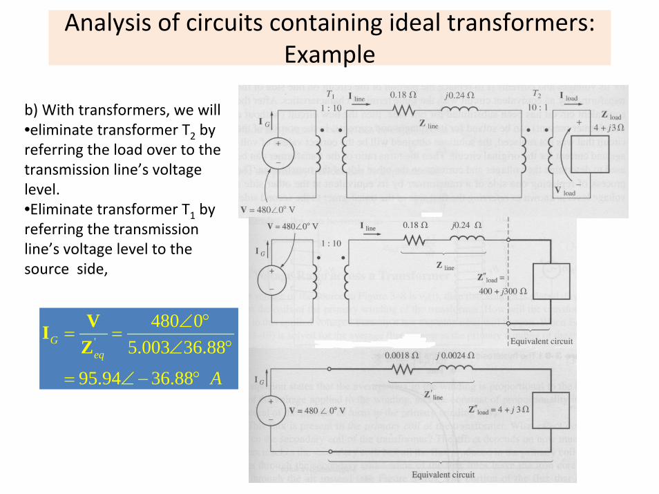
b) With transformers, we will •eliminate transformer T2 by referring the load over to the transmission line’s voltage level.•Eliminate transformer T1 by referring the transmission line’s voltage level to the source side,
'
480 05.003 36.88
95.94 36.88
Geq
A
∠ °= =
∠ °
= ∠ − °
VIZ
Analysis of circuits containing ideal transformers: Example
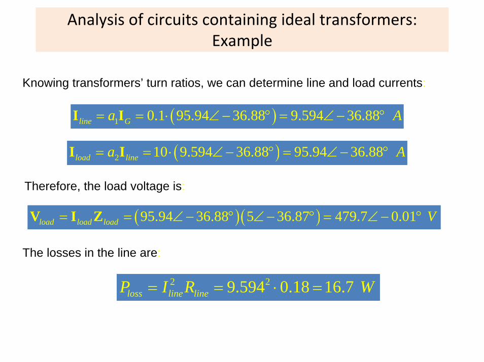
Knowing transformers’ turn ratios, we can determine line and load currents:
( )1 0.1 95.94 36.88 9.594 36.88line Ga A= = ⋅ ∠ − ° = ∠ − ° I I
( )2 10 9.594 36.88 95.94 36.88load linea A= = ⋅ ∠ − ° = ∠ − ° I I
Therefore, the load voltage is:
( )( )95.94 36.88 5 36.87 479.7 0.01load load load V= = ∠ − ° ∠ − ° = ∠ − ° V I Z
The losses in the line are:
2 29.594 0.18 16.7loss line lineP I R W= = ⋅ =
Real transformer
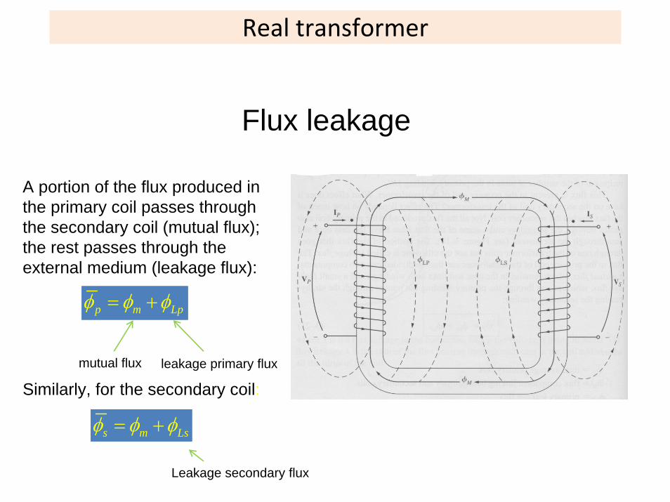
A portion of the flux produced in the primary coil passes through the secondary coil (mutual flux); the rest passes through the external medium (leakage flux):
p m Lpφ φ φ= +
leakage primary fluxmutual flux
Similarly, for the secondary coil:
s m Lsφ φ φ= +
Leakage secondary flux
Flux leakage
Real transformer
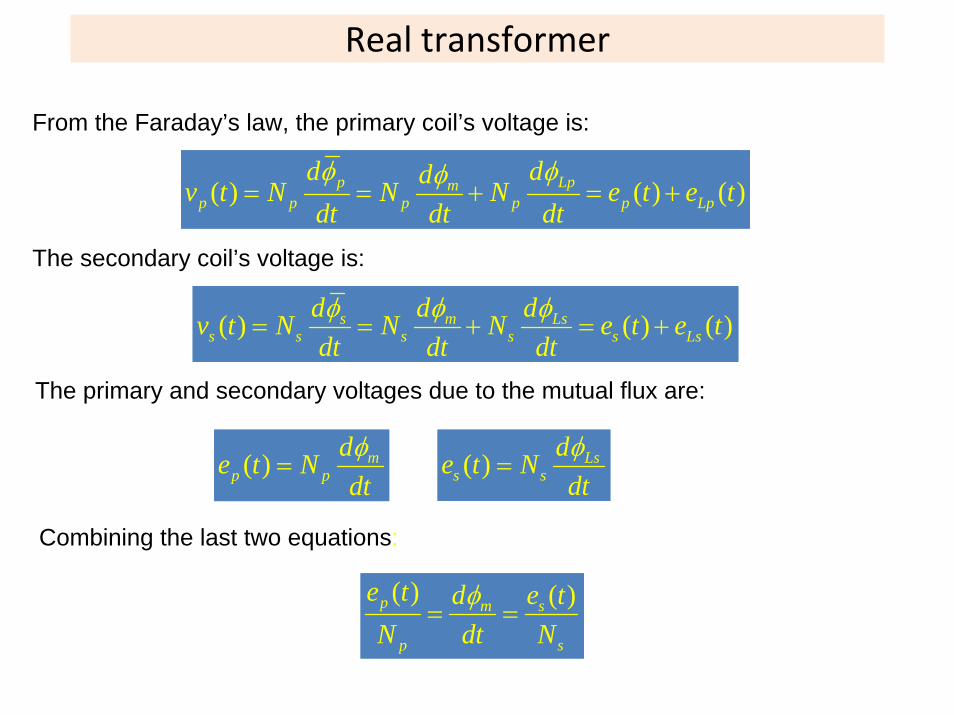
From the Faraday’s law, the primary coil’s voltage is:
( ) ( ) ( )p Lpmp p p p p Lp
d ddv t N N N e t e tdt dt dtφ φφ
= = + = +
The secondary coil’s voltage is:
( ) ( ) ( )s m Lss s s s s Ls
d d dv t N N N e t e tdt dt dtφ φ φ
= = + = +
The primary and secondary voltages due to the mutual flux are:
( ) mp p
de t Ndtφ
= ( ) Lss s
de t Ndtφ
=
Combining the last two equations:
( ) ( )p m s
p s
e t d e tN dt N
φ= =
Real transformer
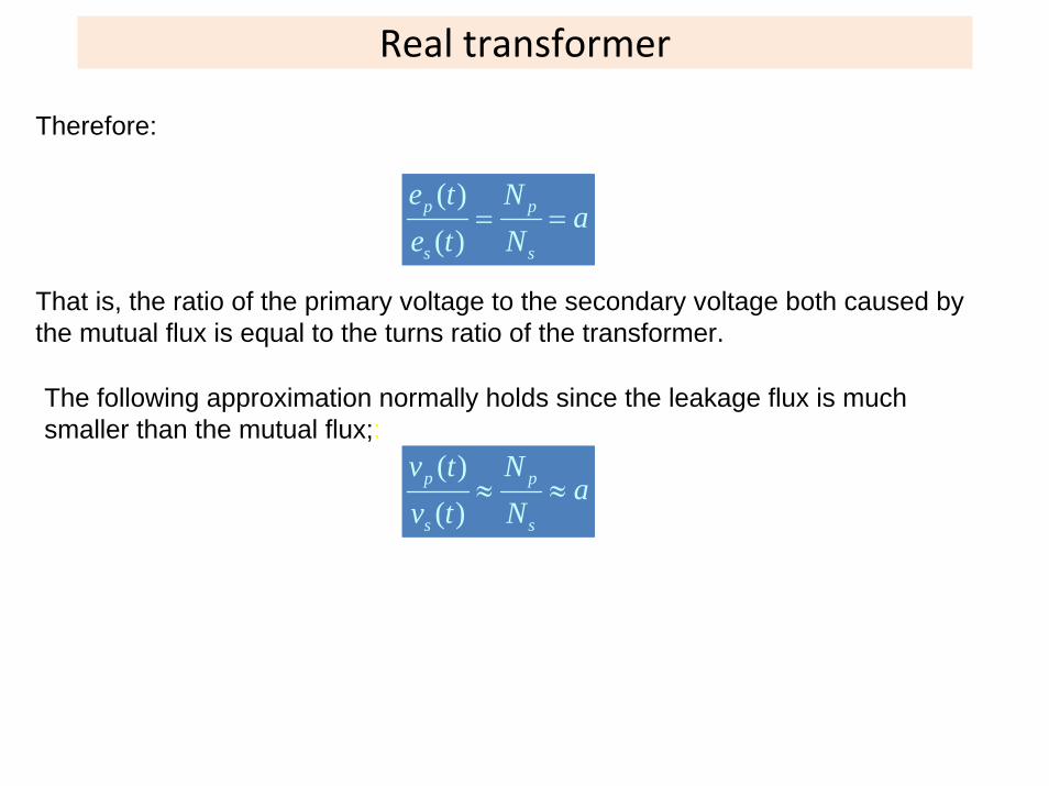
Therefore:
( )( )
p p
s s
e t Na
e t N= =
That is, the ratio of the primary voltage to the secondary voltage both caused by the mutual flux is equal to the turns ratio of the transformer.
The following approximation normally holds since the leakage flux is much smaller than the mutual flux;:
( )( )
p p
s s
v t Na
v t N≈ ≈

The magnetization current in a real transformer
Even when no load is connected to the secondary coil of the transformer, a current will flow in the primary coil. This current consists of:
1. The magnetization current im is needed to produce the flux in the core;2. The core‐loss current ih+e corresponds to hysteresis and eddy current
losses.
Typical magnetization curve
Excitation rurrent in a real transformer
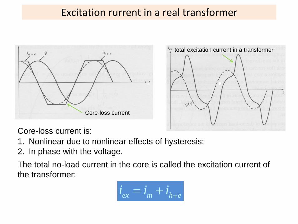
Core-loss current
Core-loss current is:
total excitation current in a transformer
1. Nonlinear due to nonlinear effects of hysteresis;2. In phase with the voltage.The total no-load current in the core is called the excitation current of the transformer:
ex m h ei i i += +
The current ratio on a transformer
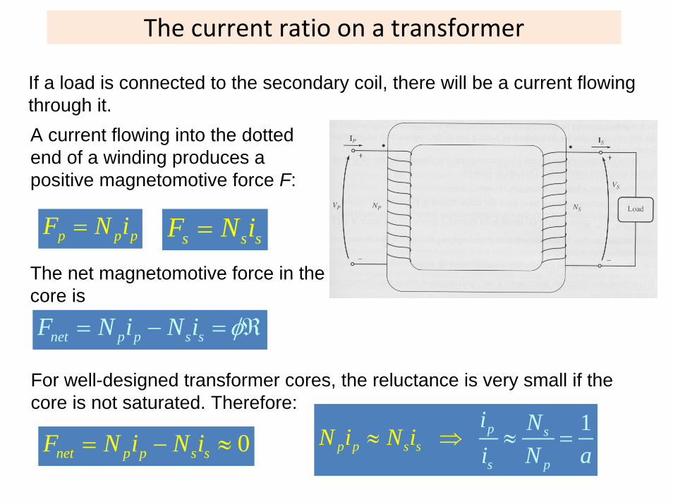
If a load is connected to the secondary coil, there will be a current flowing through it.A current flowing into the dotted end of a winding produces a positive magnetomotive force F:
p p pF N i= s s sF N i=
The net magnetomotive force in the core is
net p p s sF N i N i φ= − = ℜ
For well-designed transformer cores, the reluctance is very small if the core is not saturated. Therefore:
0net p p s sF N i N i= − ≈1p
sp
sp s
ps
i Ni N a
N i N i≈ ⇒ ≈ =
The transformer’s equivalent circuit
To model a real transformer accurately, we need to account for the following losses:
1.Copper losses – resistive heating in the windings: I2R.2.Eddy current losses – resistive heating in the core: proportional to the square of voltage applied to the transformer.3.Hysteresis losses – energy needed to rearrange magnetic domains in the core: nonlinear function of the voltage applied to the transformer.4.Leakage flux – flux that escapes from the core and flux that passes through one winding only.
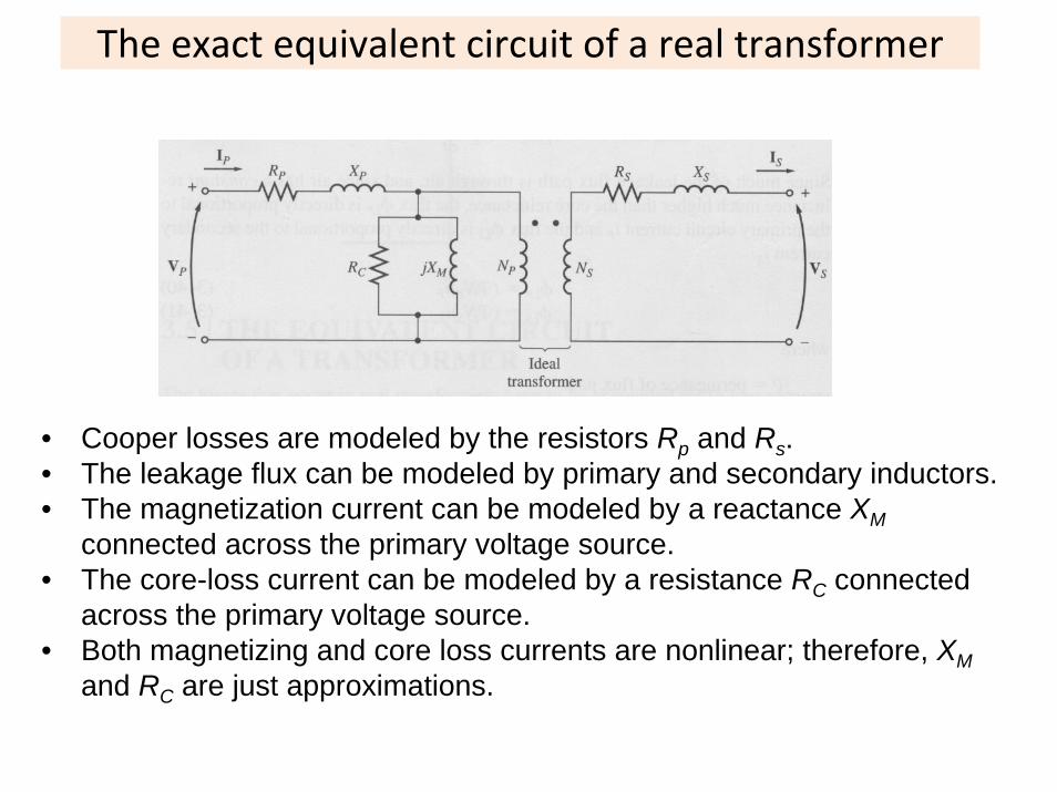
The exact equivalent circuit of a real transformer
• Cooper losses are modeled by the resistors Rp and Rs.• The leakage flux can be modeled by primary and secondary inductors.• The magnetization current can be modeled by a reactance XM
connected across the primary voltage source.• The core-loss current can be modeled by a resistance RC connected
across the primary voltage source.• Both magnetizing and core loss currents are nonlinear; therefore, XM
and RC are just approximations.
The exact equivalent circuit of a real transformer
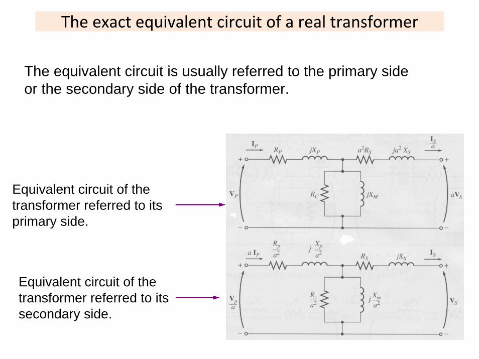
The equivalent circuit is usually referred to the primary side or the secondary side of the transformer.
Equivalent circuit of the transformer referred to its primary side.
Equivalent circuit of the transformer referred to its secondary side.
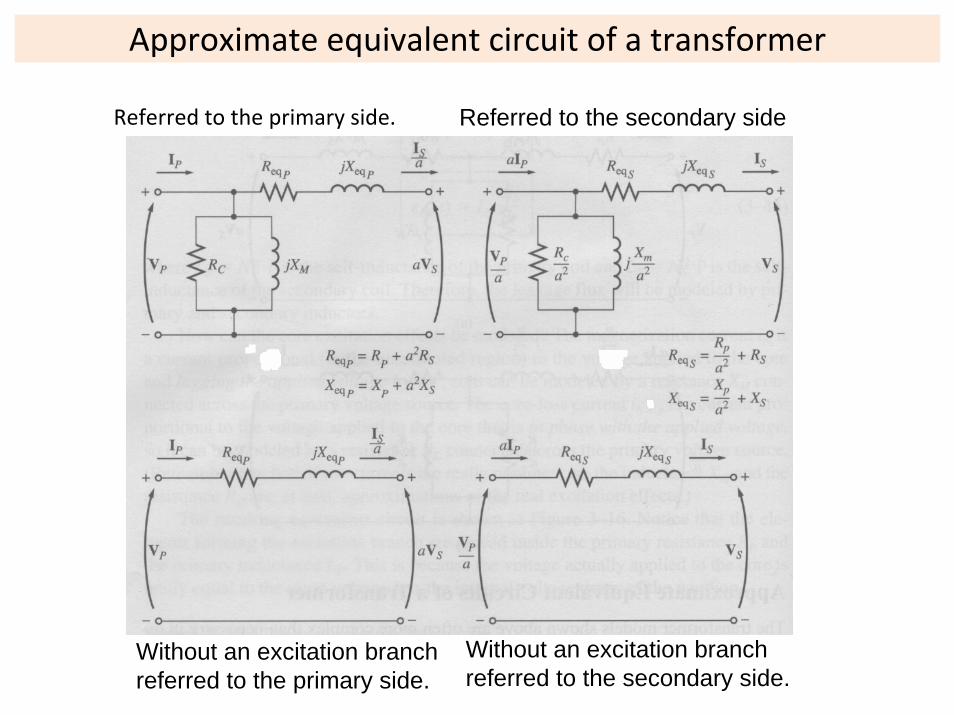
Approximate equivalent circuit of a transformer
Without an excitation branch referred to the primary side.
Without an excitation branch referred to the secondary side.
Referred to the primary side. Referred to the secondary side.
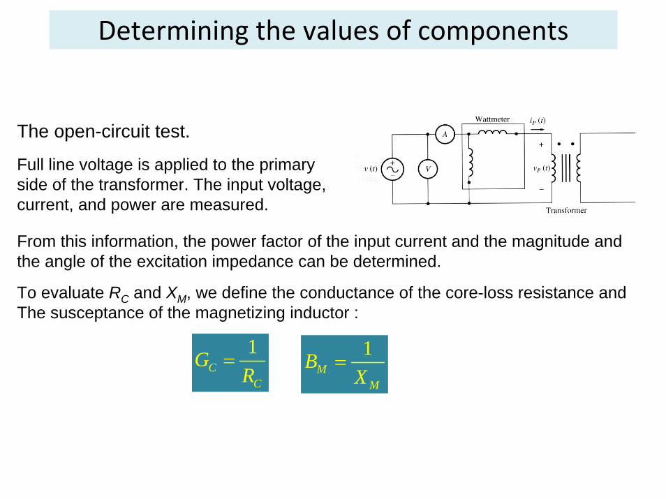
Determining the values of components
The open-circuit test.
Full line voltage is applied to the primary side of the transformer. The input voltage, current, and power are measured.
From this information, the power factor of the input current and the magnitude and the angle of the excitation impedance can be determined.
To evaluate RC and XM, we define the conductance of the core-loss resistance and The susceptance of the magnetizing inductor :
1C
C
GR
= 1M
M
BX
=
Determining the values of components
1 1E C M
C M
Y G jB jR X
= − = −
ocE
oc
IYV
=
cos oc
oc oc
PPFV I
θ = =
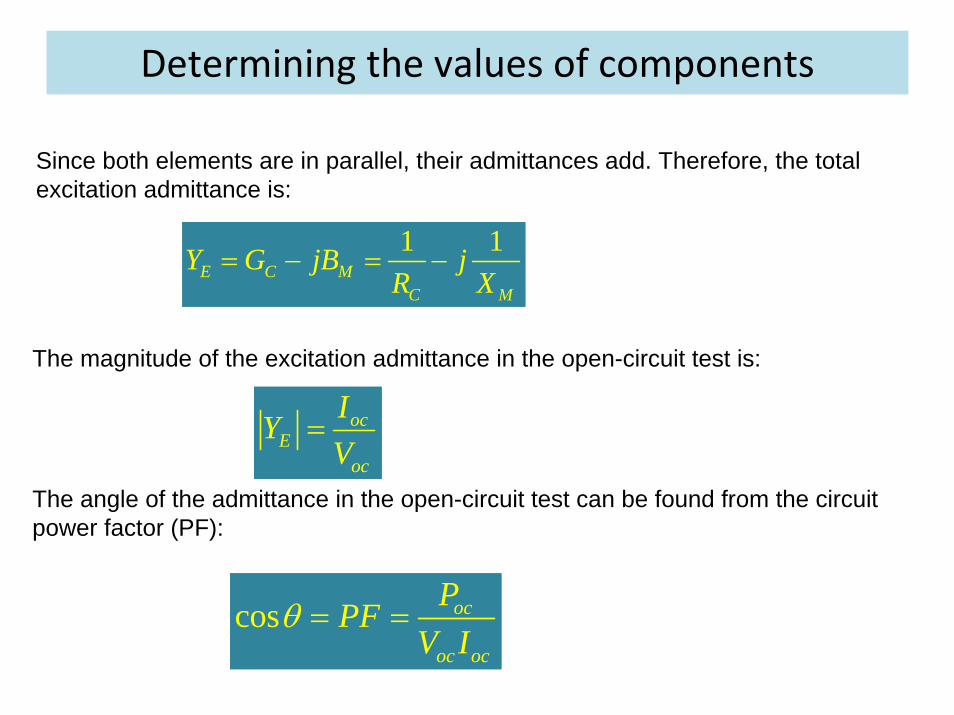
Since both elements are in parallel, their admittances add. Therefore, the total excitation admittance is:
The magnitude of the excitation admittance in the open-circuit test is:
The angle of the admittance in the open-circuit test can be found from the circuit power factor (PF):
Determining the values of components
1cosoc ocE
oc oc
I IY PFV V
θ −= ∠ − = ∠ −
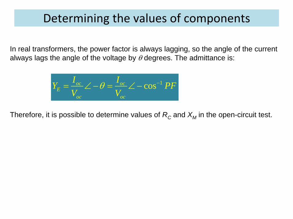
In real transformers, the power factor is always lagging, so the angle of the current always lags the angle of the voltage by θ degrees. The admittance is:
Therefore, it is possible to determine values of RC and XM in the open-circuit test.
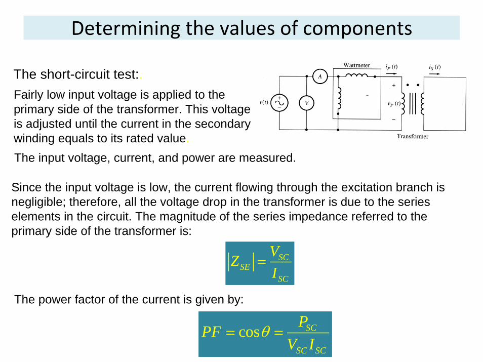
Since the input voltage is low, the current flowing through the excitation branch is negligible; therefore, all the voltage drop in the transformer is due to the series elements in the circuit. The magnitude of the series impedance referred to the primary side of the transformer is:
Determining the values of components
SCSE
SC
VZI
=
cos SC
SC SC
PPFV I
θ= =
The short-circuit test:.Fairly low input voltage is applied to the primary side of the transformer. This voltage is adjusted until the current in the secondary winding equals to its rated value. The input voltage, current, and power are measured.
The power factor of the current is given by:
Determining the values of components
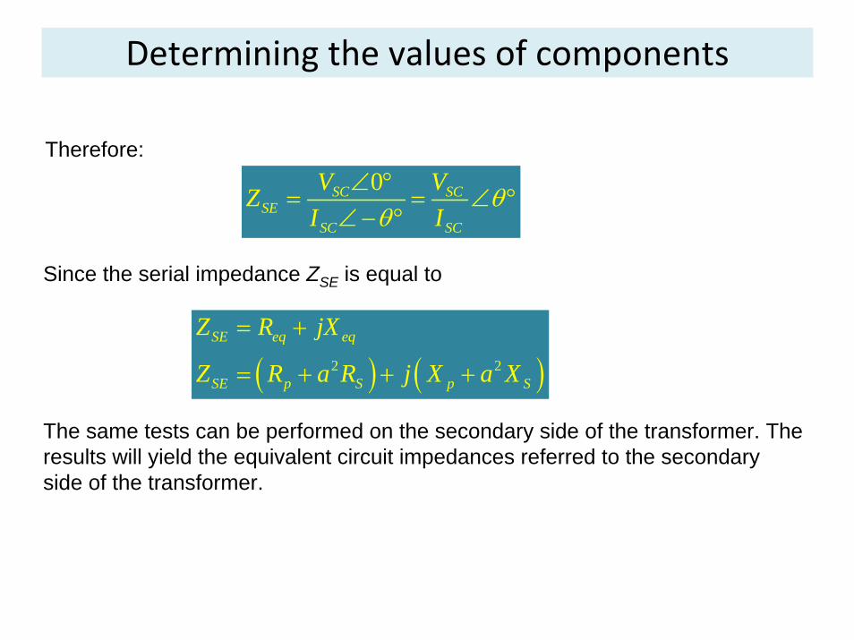
0SC SCSE
SC SC
V VZI I
θθ
∠ °= = ∠ °
∠ − °
( ) ( )2 2
SE eq eq
SE p S p S
Z R jX
Z R a R j X a X
= +
= + + +
Therefore:
Since the serial impedance ZSE is equal to
The same tests can be performed on the secondary side of the transformer. The results will yield the equivalent circuit impedances referred to the secondary side of the transformer.
Example
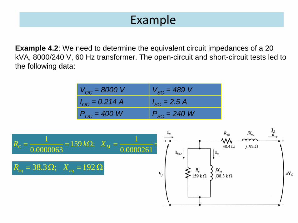
Example 4.2: We need to determine the equivalent circuit impedances of a 20kVA, 8000/240 V, 60 Hz transformer. The open-circuit and short-circuit tests led to the following data:
VOC = 8000 V VSC = 489 VIOC = 0.214 A ISC = 2.5 APOC = 400 W PSC = 240 W
1 1159 ; 38.30.0000063 0.0000261C MR k X k= = Ω = = Ω
38.3 ; 192eq eqR X= Ω = Ω
The per‐unit system
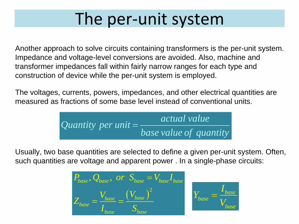
actual valueQuantity per unitbase value of quantity
=
( )2
, ,base base base base base
basebasebase
base base
P Q or S V I
VVZI S
=
= =
Another approach to solve circuits containing transformers is the per-unit system. Impedance and voltage-level conversions are avoided. Also, machine and transformer impedances fall within fairly narrow ranges for each type and construction of device while the per-unit system is employed.
The voltages, currents, powers, impedances, and other electrical quantities are measured as fractions of some base level instead of conventional units.
Usually, two base quantities are selected to define a given per-unit system. Often, such quantities are voltage and apparent power . In a single-phase circuits:
basebase
base
IYV
=
The per‐unit system
Once the base values of P (or S) and V are selected, all other base values can be computed form the above equations.
In a power system, a base apparent power and voltage are selected at the specific point in the system.
Note that a transformer has no effect on the apparent power of the system, since the apparent power into a transformer equals the apparent power out of a transformer. As a result, the base apparent power remains constant everywhere in the power system.
On the other hand, voltage (and, therefore, a base voltage) changes when it goes through a transformer according to its turn ratio. Therefore, the process of referring quantities to a common voltage level is done automatically in the per-unit system.
The per‐unit system: Example
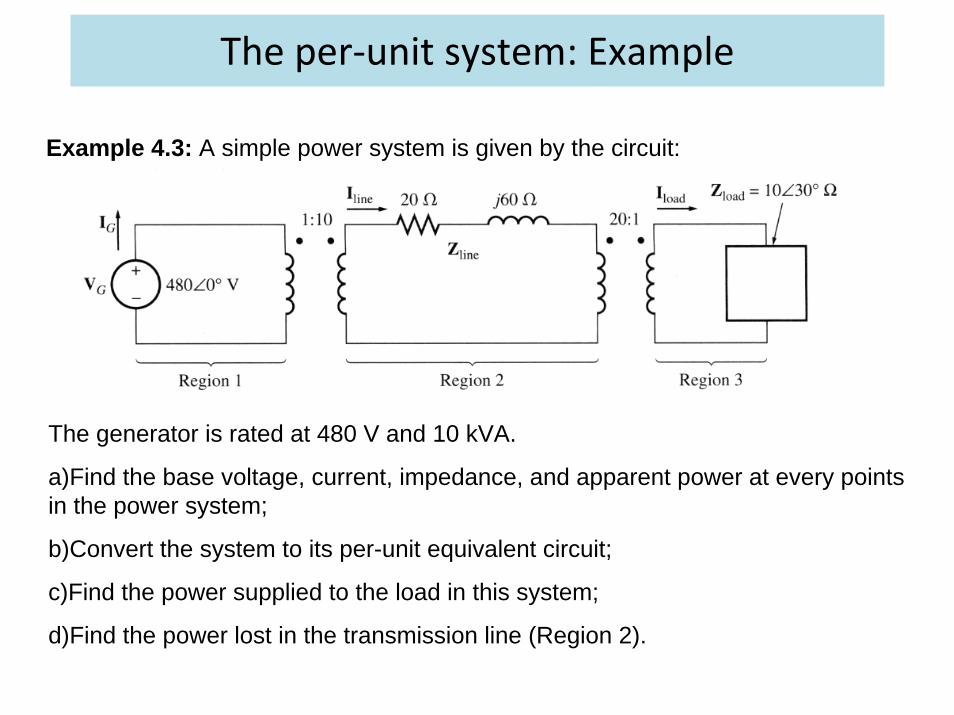
Example 4.3: A simple power system is given by the circuit:
The generator is rated at 480 V and 10 kVA.
a)Find the base voltage, current, impedance, and apparent power at every points in the power system;
b)Convert the system to its per-unit equivalent circuit;
c)Find the power supplied to the load in this system;
d)Find the power lost in the transmission line (Region 2).
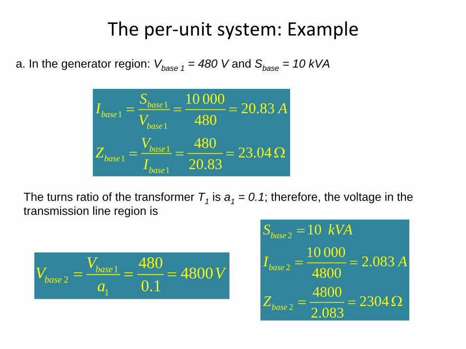
The per‐unit system: Example
11
1
11
1
10 000 20.83480480 23.04
20.83
basebase
base
basebase
base
SI AVVZI
= = =
= = = Ω
12
1
480 48000.1
basebase
VV Va
= = =
a. In the generator region: Vbase 1 = 480 V and Sbase = 10 kVA
The turns ratio of the transformer T1 is a1 = 0.1; therefore, the voltage in the transmission line region is
2
2
2
1010 000 2.08348004800 23042.083
base
base
base
S kVA
I A
Z
=
= =
= = Ω
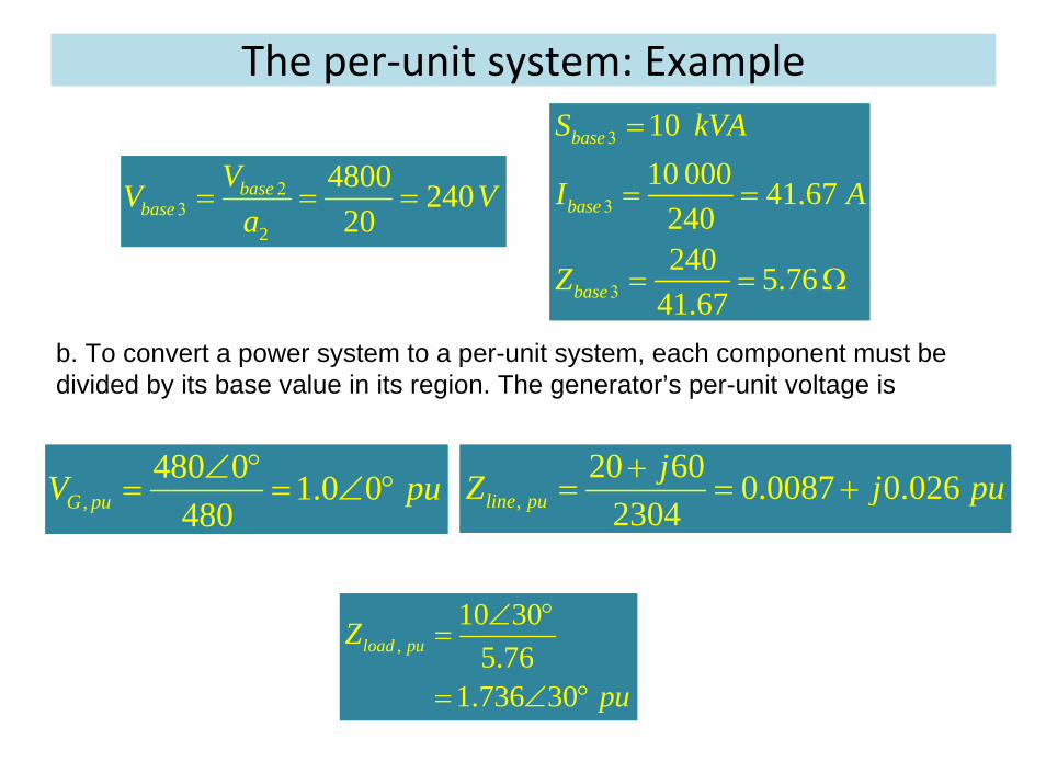
The per‐unit system: Example
2
4800 24020
basebase
VV Va
2 3 = = =
1010 000 41.67
240240 5.76
41.67
base
base
base
S kVA
I A
Z
3
3
3
=
= =
= = Ω
b. To convert a power system to a per-unit system, each component must be divided by its base value in its region. The generator’s per-unit voltage is
,480 0 1.0 0
480G puV pu∠ °= = ∠ ° ,
20 60 0.0087 0.0262304line pu
jZ j pu
+= = +
,10 30
5.761.736 30
load puZ
pu
∠ °=
= ∠ °
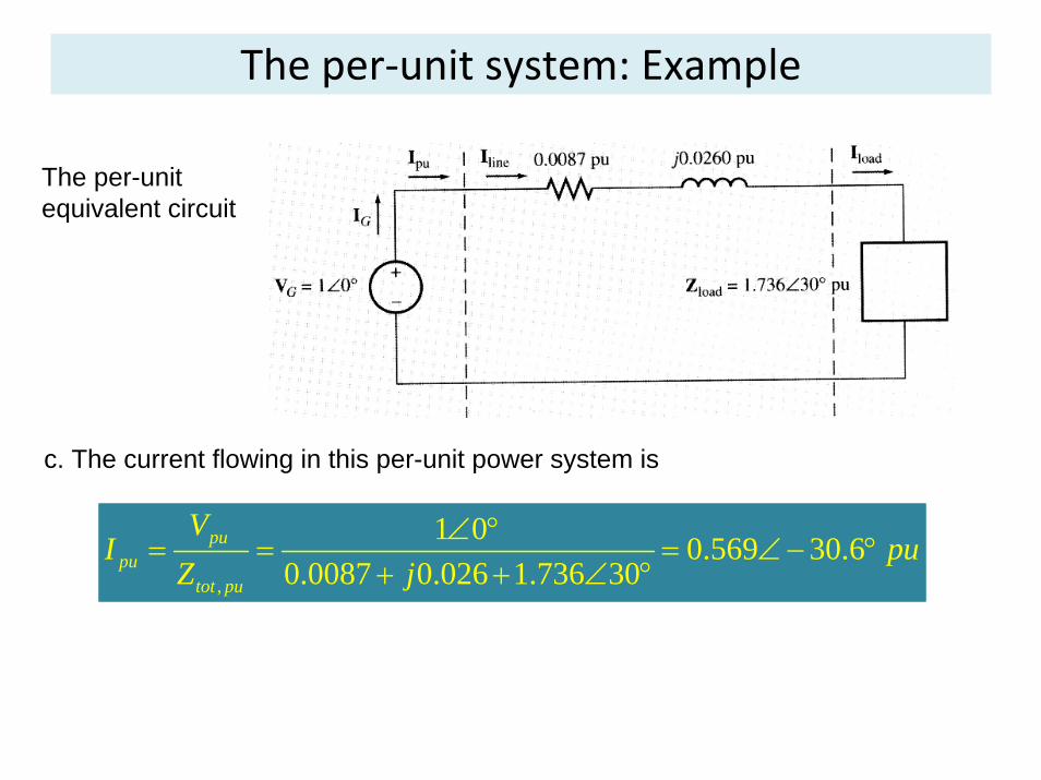
The per‐unit system: Example
,
1 0 0.569 30.60.0087 0.026 1.736 30
pupu
tot pu
VI pu
Z j∠ °
= = = ∠ − ° + + ∠ °
The per-unit equivalent circuit
c. The current flowing in this per-unit power system is

The per‐unit system: Example
2 2, 0.569 1.503 0.487load pu pu puP I R = = ⋅ =
, 0.487 10 000 487load load pu baseP P S W= = ⋅ =
2 2, , 0.569 0.0087 0.00282line pu pu line puP I R = = ⋅ =
, 0.00282 10 000 8.2line line pu baseP P S W= = ⋅ = 2
Therefore, the per-unit power on the load is
The actual power on the load is
d. The per-unit power lost in the transmission line is
The actual power lost in the transmission line
The per‐unit system
• When only one device is analyzed, its own rating is used as the basis for per-unit system.
• If more than one transformer is present in a system, the system base voltage and power can be chosen arbitrary.
• However, the entire system must have the same base power, and the base voltages at various points in the system must be related by the voltage ratios of the transformers.
• System base quantities are commonly chosen to equal the base of the largest component in the system.
The per‐unit system: Example
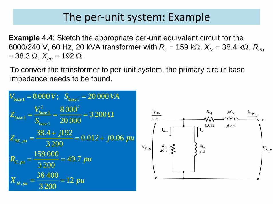
1 12 2
11
1
,
,
,
8 000 ; 20 000
8 000 3 20020 000
38.4 192 0.012 0.063 200
159 000 49.73 200
00 123 200
base base
basebase
base
SE pu
C pu
M pu
V V S VA
VZS
jZ j pu
R pu
X pu
= =
= = = Ω
+
= = +
= =
38 4
= =
Example 4.4: Sketch the appropriate per-unit equivalent circuit for the 8000/240 V, 60 Hz, 20 kVA transformer with Rc = 159 kΩ, XM = 38.4 kΩ, Req= 38.3 Ω, Xeq = 192 Ω.
To convert the transformer to per-unit system, the primary circuit base impedance needs to be found.

Voltage Regulation (VR)
, , ,
, ,
100% 100%s nl s fl p s fl
s fl s fl
V V V a VVR
V V− −
= ⋅ = ⋅
, , ,
, ,
100%p pu s fl pu
s fl pu
V VVR
V−
= ⋅
Since a real transformer contains series impedances, the transformer’s output voltage varies with the load even if the input voltage is constant. To compare transformers in this respect, the quantity called a full-load voltage regulation (VR) is defined as follows:
In a per-unit system:
Note: the VR of an ideal transformer is zero.
Where Vs,nl and Vs,fl are the secondary no load and full load voltages.
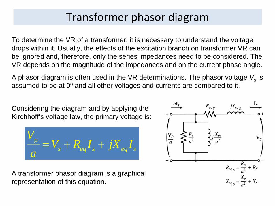
Transformer phasor diagram
ps eq s eq s
VV R I jX I
a= + +
To determine the VR of a transformer, it is necessary to understand the voltage drops within it. Usually, the effects of the excitation branch on transformer VR can be ignored and, therefore, only the series impedances need to be considered. The VR depends on the magnitude of the impedances and on the current phase angle.
A phasor diagram is often used in the VR determinations. The phasor voltage Vs is assumed to be at 00 and all other voltages and currents are compared to it.
Considering the diagram and by applying the Kirchhoff’s voltage law, the primary voltage is:
A transformer phasor diagram is a graphical representation of this equation.

Transformer phasor diagram
A transformer operating at a lagging power factor:
It is seen that Vp/a > Vs, VR > 0
A transformer operating at a unity power factor:
It is seen that VR > 0
A transformer operating at a leading power factor:
If the secondary current is leading, the secondary voltage can be higher than the referred primary voltage; VR < 0.
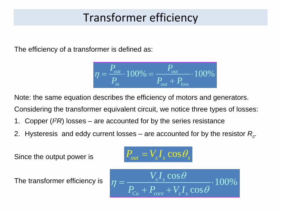
Considering the transformer equivalent circuit, we notice three types of losses:
Transformer efficiency
100% 100%out out
in out loss
P PP P P
η = ⋅ = ⋅+
cosout s s sP V I θ=
cos 100%cos
s s
Cu core s s
V IP P V I
θηθ
= ⋅+ +
The efficiency of a transformer is defined as:
Note: the same equation describes the efficiency of motors and generators.
1. Copper (I2R) losses – are accounted for by the series resistance
2. Hysteresis and eddy current losses – are accounted for by the resistor Rc.
Since the output power is
The transformer efficiency is
The transformer efficiency: Example
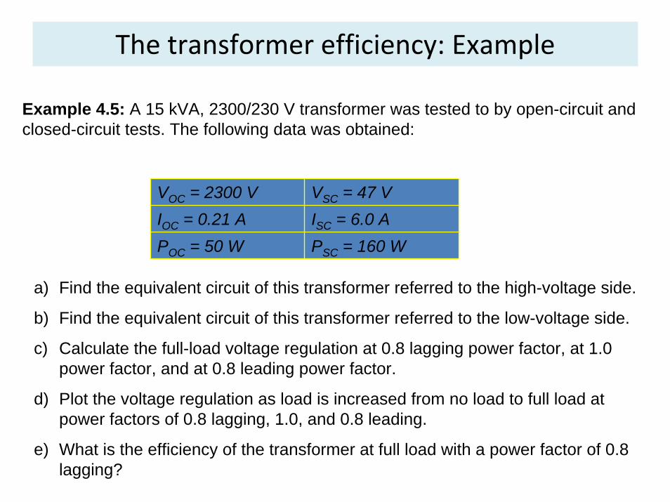
VOC = 2300 V VSC = 47 VIOC = 0.21 A ISC = 6.0 APOC = 50 W PSC = 160 W
Example 4.5: A 15 kVA, 2300/230 V transformer was tested to by open-circuit and closed-circuit tests. The following data was obtained:
a) Find the equivalent circuit of this transformer referred to the high-voltage side.
b) Find the equivalent circuit of this transformer referred to the low-voltage side.
c) Calculate the full-load voltage regulation at 0.8 lagging power factor, at 1.0 power factor, and at 0.8 leading power factor.
d) Plot the voltage regulation as load is increased from no load to full load at power factors of 0.8 lagging, 1.0, and 0.8 leading.
e) What is the efficiency of the transformer at full load with a power factor of 0.8 lagging?
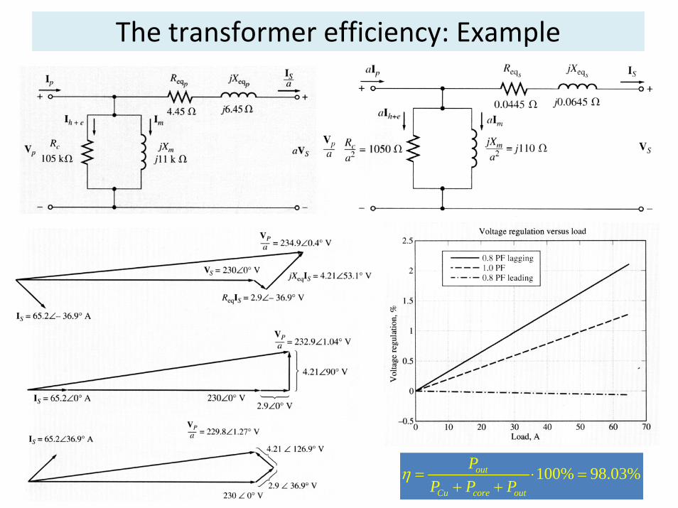
The transformer efficiency: Example
100% 98.03%out
Cu core out
PP P P
η = ⋅ =+ +
Transformer taps and voltage regulation
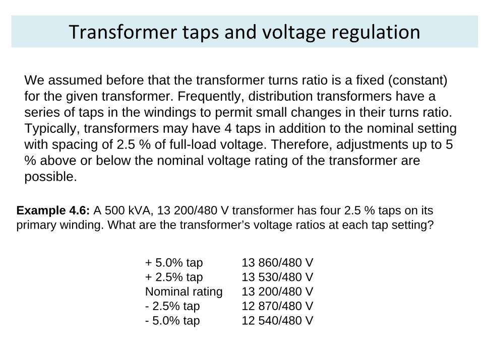
We assumed before that the transformer turns ratio is a fixed (constant) for the given transformer. Frequently, distribution transformers have a series of taps in the windings to permit small changes in their turns ratio. Typically, transformers may have 4 taps in addition to the nominal setting with spacing of 2.5 % of full-load voltage. Therefore, adjustments up to 5 % above or below the nominal voltage rating of the transformer are possible.
Example 4.6: A 500 kVA, 13 200/480 V transformer has four 2.5 % taps on its primary winding. What are the transformer’s voltage ratios at each tap setting?
+ 5.0% tap 13 860/480 V+ 2.5% tap 13 530/480 VNominal rating 13 200/480 V- 2.5% tap 12 870/480 V- 5.0% tap 12 540/480 V
Transformer taps and voltage regulation
Taps allow adjustment of the transformer in the field to accommodate for local voltage variations.Sometimes, transformers are used on a power line, whose voltage varies widely with the load (due to high line impedance, for instance). Normal loads need fairly constant input voltage though…One possible solution to this problem is to use a special transformer called a tap changing under load (TCUL) transformer or voltage regulator. TCUL is a transformer with the ability to change taps while power is connected to it. A voltage regulator is a TCUL with build-in voltage sensing circuitry that automatically changes taps to keep the system voltage constant.These “self-adjusting” transformers are very common in modern power systems.
The autotransformer
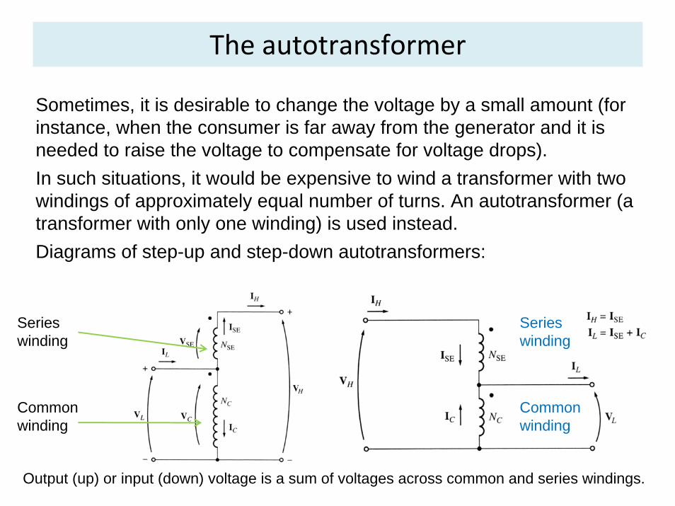
Sometimes, it is desirable to change the voltage by a small amount (for instance, when the consumer is far away from the generator and it is needed to raise the voltage to compensate for voltage drops).In such situations, it would be expensive to wind a transformer with two windings of approximately equal number of turns. An autotransformer (a transformer with only one winding) is used instead. Diagrams of step-up and step-down autotransformers:
Common winding
Series winding
Series winding
Common winding
Output (up) or input (down) voltage is a sum of voltages across common and series windings.
The autotransformer
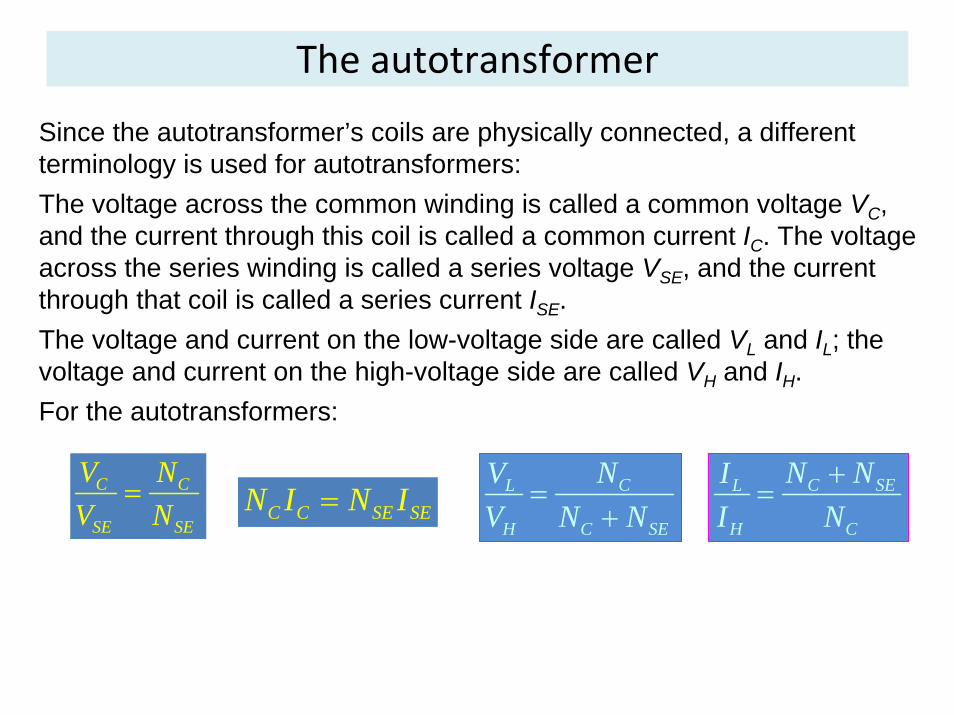
Since the autotransformer’s coils are physically connected, a different terminology is used for autotransformers:The voltage across the common winding is called a common voltage VC, and the current through this coil is called a common current IC. The voltage across the series winding is called a series voltage VSE, and the current through that coil is called a series current ISE.The voltage and current on the low-voltage side are called VL and IL; the voltage and current on the high-voltage side are called VH and IH.For the autotransformers:
C C
SE SE
V NV N
=C C SE SEN I N I= CL
H C SE
NVV N N
=+
C SEL
H C
N NII N
+=
The apparent power advantage
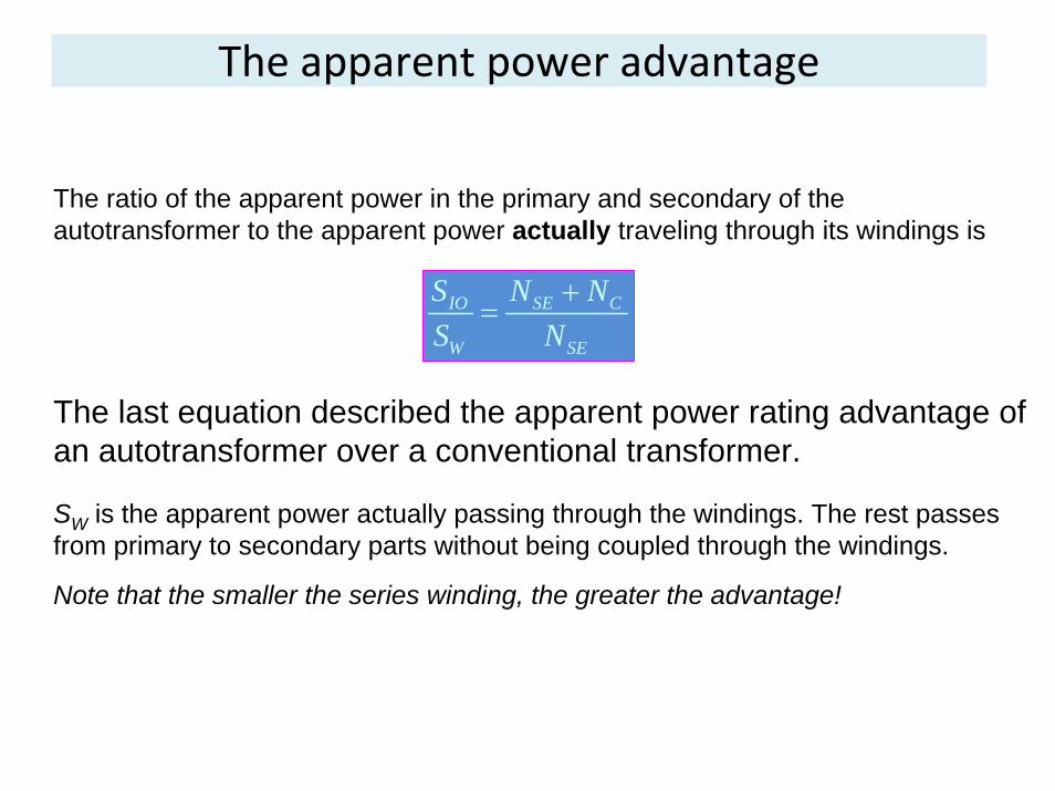
The ratio of the apparent power in the primary and secondary of the autotransformer to the apparent power actually traveling through its windings is
IO SE C
W SE
S N NS N
+=
The last equation described the apparent power rating advantage of an autotransformer over a conventional transformer.
SW is the apparent power actually passing through the windings. The rest passes from primary to secondary parts without being coupled through the windings.
Note that the smaller the series winding, the greater the advantage!
The apparent power advantage
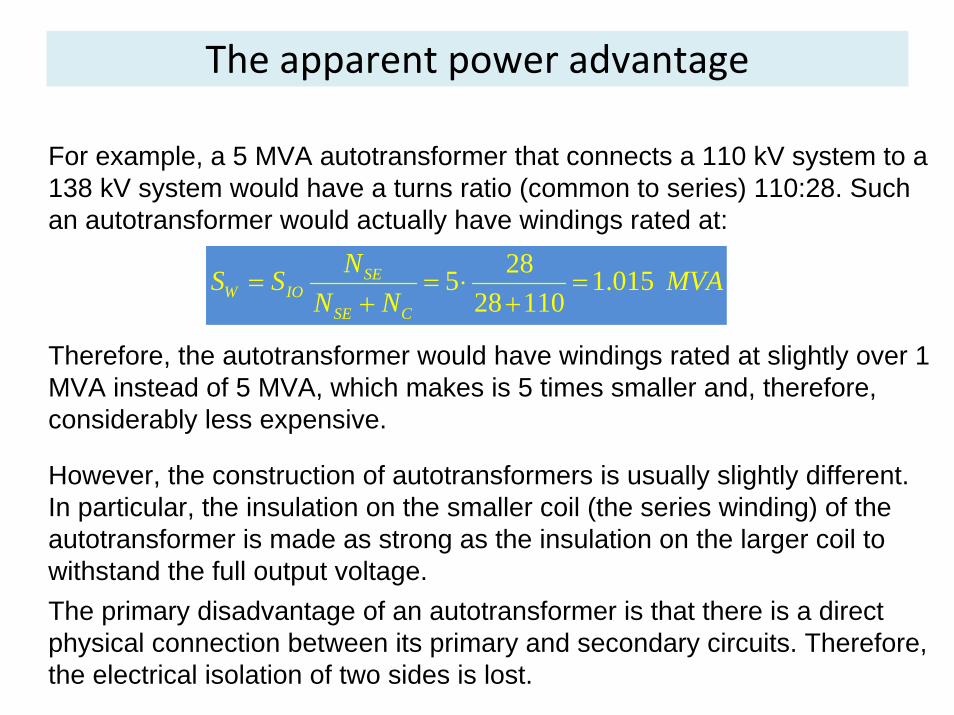
For example, a 5 MVA autotransformer that connects a 110 kV system to a 138 kV system would have a turns ratio (common to series) 110:28. Such an autotransformer would actually have windings rated at:
285 1.01528 110
SEW IO
SE C
NS S MVAN N
= = ⋅ = + +
Therefore, the autotransformer would have windings rated at slightly over 1 MVA instead of 5 MVA, which makes is 5 times smaller and, therefore, considerably less expensive.
However, the construction of autotransformers is usually slightly different. In particular, the insulation on the smaller coil (the series winding) of the autotransformer is made as strong as the insulation on the larger coil to withstand the full output voltage.The primary disadvantage of an autotransformer is that there is a direct physical connection between its primary and secondary circuits. Therefore, the electrical isolation of two sides is lost.
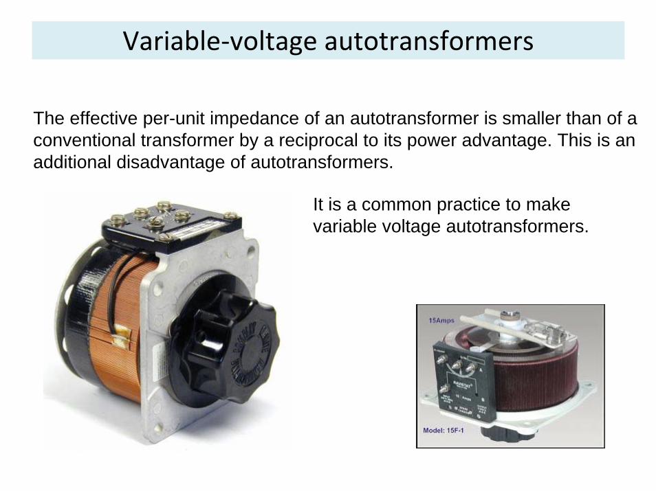
Variable‐voltage autotransformers
It is a common practice to make variable voltage autotransformers.
The effective per-unit impedance of an autotransformer is smaller than of a conventional transformer by a reciprocal to its power advantage. This is an additional disadvantage of autotransformers.
3‐phase transformers
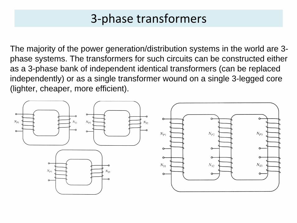
The majority of the power generation/distribution systems in the world are 3-phase systems. The transformers for such circuits can be constructed either as a 3-phase bank of independent identical transformers (can be replaced independently) or as a single transformer wound on a single 3-legged core (lighter, cheaper, more efficient).
3‐phase transformer connections
We assume that any single transformer in a 3-phase transformer (bank) behaves exactly as a single-phase transformer. The impedance, voltage regulation, efficiency, and other calculations for 3-phase transformers are done on a per-phase basis, using the techniques studied previously for single-phase transformers.
Four possible connections for a 3-phase transformer bank are:1. Y-Y2. Y-Δ3. Δ- Δ4. Δ-Y

3‐phase transformer connections
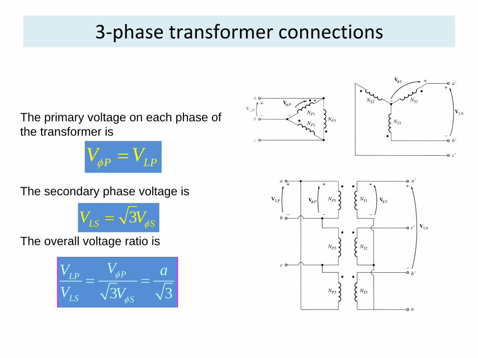
1. Y-Y connection:The primary voltage on each phase of the transformer is
3LP
PVVφ =
The secondary phase voltage is
3LS SV Vφ=The overall voltage ratio is
33
PLP
LS S
VV aV V
φ
φ
= =
3‐phase transformer connections
3. Δ -Y connection:The primary voltage on each phase of the transformer is
P LPV Vφ =
The secondary phase voltage is
3LS SV Vφ=The overall voltage ratio is
3 3PLP
LS S
VV aV V
φ
φ
= =
The same advantages and the same phase shift as the Y-Δ connection.
3‐phase transformer connections
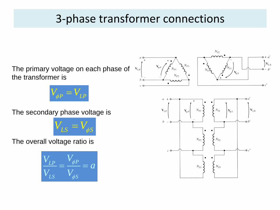
4. Δ - Δ connection:The primary voltage on each phase of the transformer is
P LPV Vφ =
The secondary phase voltage is
LS SV Vφ=The overall voltage ratio is
PLP
LS S
VV aV V
φ
φ
= =
No phase shift, no problems with unbalanced loads or harmonics.
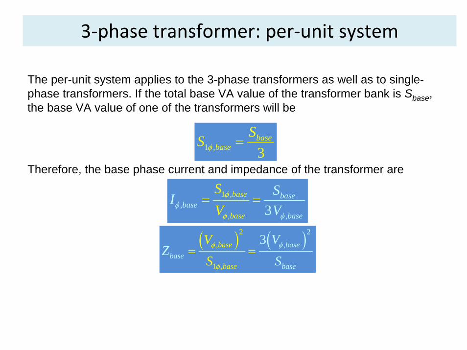
3‐phase transformer: per‐unit system
The per-unit system applies to the 3-phase transformers as well as to single-phase transformers. If the total base VA value of the transformer bank is Sbase, the base VA value of one of the transformers will be
1 , 3base
baseSS φ =
Therefore, the base phase current and impedance of the transformer are
1 ,
,,
,3base
b
baseba
ass
baee
se
SV
SI
Vφφ
φ
φ = =
( ) ( )2
,
1
,
,
23base
bas
basebase
basee
VZ
SVS
φ φ
φ
= =
3‐phase transformer: per‐unit system
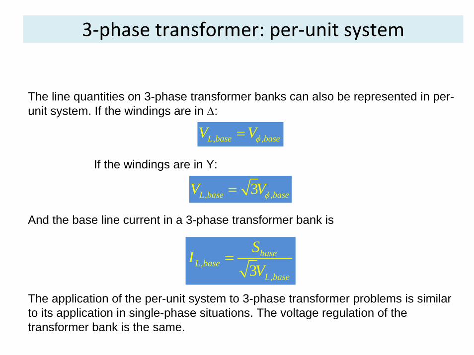
The line quantities on 3-phase transformer banks can also be represented in per-unit system. If the windings are in Δ:
, ,L base baseV Vφ=
, ,3L base baseV Vφ=
If the windings are in Y:
And the base line current in a 3-phase transformer bank is
,,3
baseL base
L base
SIV
=
The application of the per-unit system to 3-phase transformer problems is similar to its application in single-phase situations. The voltage regulation of the transformer bank is the same.
Transformer ratings: Voltage and Frequency
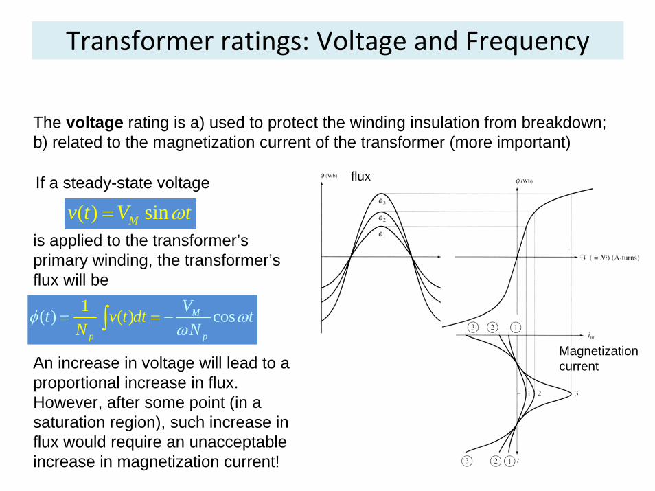
The voltage rating is a) used to protect the winding insulation from breakdown; b) related to the magnetization current of the transformer (more important)
If a steady-state voltage
( ) sinMv t V tω=is applied to the transformer’s primary winding, the transformer’s flux will be
( ) c) o1 s( M
p p
v t d Vt tN
tN
φ ωω
== −∫
An increase in voltage will lead to a proportional increase in flux. However, after some point (in a saturation region), such increase in flux would require an unacceptable increase in magnetization current!
flux
Magnetization current
Transformer ratings: Voltage and Frequency
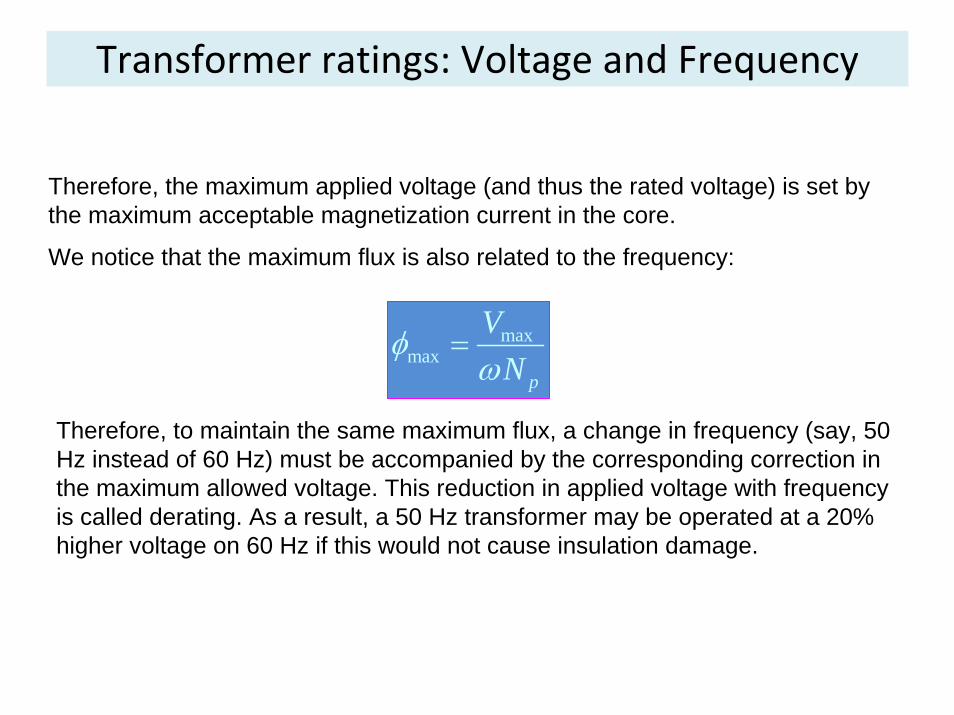
Therefore, the maximum applied voltage (and thus the rated voltage) is set by the maximum acceptable magnetization current in the core.
We notice that the maximum flux is also related to the frequency:
maxmax
p
VN
φω
=
Therefore, to maintain the same maximum flux, a change in frequency (say, 50 Hz instead of 60 Hz) must be accompanied by the corresponding correction in the maximum allowed voltage. This reduction in applied voltage with frequency is called derating. As a result, a 50 Hz transformer may be operated at a 20% higher voltage on 60 Hz if this would not cause insulation damage.
Transformer ratings: Apparent Power
The apparent power rating sets (together with the voltage rating) the current through the windings. The current determines the i2R losses and, therefore, the heating of the coils. Remember, overheating shortens the life of transformer’s insulation!
In addition to apparent power rating for the transformer itself, additional higher rating(s) may be specified if a forced cooling is used. Under any circumstances, the temperature of the windings must be limited.
Note, that if the transformer’s voltage is reduced (for instance, the transformer is working at a lower frequency), the apparent power rating must be reduced by an equal amount to maintain the constant current.
Transformer ratings: Current inrush
Assuming that the following voltage is applied to the transformer at the moment it is connected to the line:
( )( ) sinMv t V tω θ= +
The maximum flux reached on the first half-cycle depends on the phase of the voltage at the instant the voltage is applied. If the initial voltage is
( )( ) sin 90 cosM Mv t V t V tω ω= + ° =and the initial flux in the core is zero, the maximum flux during the first half-cycle is equals to the maximum steady-state flux (which is ok):
maxM
p
VN
φω
=
However, if the voltage’s initial phase is zero, i.e.
( )( ) sinMv t V tω=
Transformer ratings: Current inrush
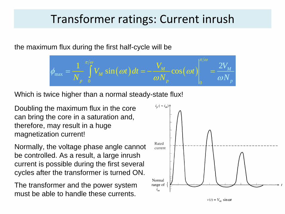
the maximum flux during the first half-cycle will be
( ) ( )0
max0
1 si 2n cos MMM
p pp
VV t dt tN N
VN
π ωπ ω
ωω
φω
ω = − == ∫
Which is twice higher than a normal steady-state flux!
Doubling the maximum flux in the core can bring the core in a saturation and, therefore, may result in a huge magnetization current!
Normally, the voltage phase angle cannot be controlled. As a result, a large inrush current is possible during the first several cycles after the transformer is turned ON.
The transformer and the power system must be able to handle these currents.
Transformer ratings: Information Plate
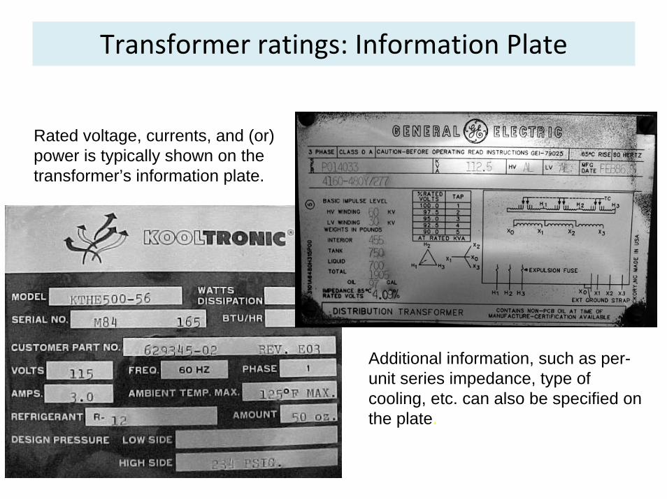
Rated voltage, currents, and (or) power is typically shown on the transformer’s information plate.
Additional information, such as per-unit series impedance, type of cooling, etc. can also be specified on the plate.

Instrument transformers
Two special-purpose transformers are uses to take measurements: potential and current transformers.
A potential transformer has a high-voltage primary, low-voltage secondary, and very low power rating. It is used to provide an accurate voltage samples to instruments monitoring the power system.
A current transformer samples the current in a line and reduces it to a safe and measurable level. Such transformer consists of a secondary winding wrapped around a ferromagnetic ring with a single primary line running through its center.
The secondary current is directly proportional to the primary.
Current transformers must not be open-circuited since very high voltages can appear across their terminals.

Practice Problems
• 3.1‐3.8
• 3.14‐3.16
• 3.18
• 3.21