yak-52 operating handbook
DESCRIPTION
Operating manual for Yak 52.TRANSCRIPT

1

YAK 52 Front Cockpit
A Enunciator Lights mp
/Pitot Ht
xtn.
Primer/Wobble puAudio Panel Radio
en/IgnBatt/GCooling Controls Carb. Heat
Gear EEmergencyCabin Heat
l Panel ADF ControWheel brakes Compass
Elevator Trim
ch ff
Lights
Flaps le Thrott
Prop. PitFuel Cut-OMagnetos
ear Landing GLanding Gear Air Pressure Gauge Accelerometer
L M N P Q R S T U V W X
B C D E F G H J
K
2

YAK 52 Front Cockpit
Manifold Pressure (in cms of Hg) RPM in percent Airspeed Indicator Altimeter Clock / Stop watch / Timer Attitude Indicator Gyro Compass / ADF / RMI Turn & Bank / Rate of Climb Indicator Oil Temp, Oil Pressure, Fuel Pressure Carb. Inlet Temperature Cylinder Head Temperature Voltmeter / Ammeter Digital Fuel Gauge
A B C D E F G H I J K L M
3

21
Aircraft Dimensions Overall length 25 ft Wingspan 30 ft Height 9 ft Wing area 157 sq ft Dihedral 2 degrees Wing incidence 2 degrees Gyro compass The Gyro compass installed in the Yak 52 is a slaved gyro with latitude compensation. It may be operated in a slaved or free mode. To operate the unit in FREE mode, set the SLAVE/FREE switch to FREE and adjust the heading indicator with the ADJUST switch. To more quickly set the heading, use the 0 deg. / 300 deg. switch to set the compass to those headings.
To use the Gyro in slaved mode, in which it will automatically align its self to an internal magnetic compass, set the switch to SLAVE (forward), set the North/south switch to NORTH (forward) for northern hemisphere and using the large tuning knob in the center of the panel, set your approximate latitude in the latitude window. The unit will now automatically compensate for compass errors and the instrument face will indicate your exact magnetic heading. The most usual way to operate the gyro-compass is with all four switches in the forward or spring-loaded positions.
4

20
Radio compass The radio compass installed in the Yak 52 allows the selection of 8 stations whose frequency is determined in the electronics box installed behind the seat of the rear cockpit. Eight channels may be selected from the cockpit. Select channels 1 to 4 by means of the large knob mounted at the forward end of the control panel. To select the second four channels, the switch mounted on the top left of the instrument panel coaming should be moved to the second position. The channel selector knob will now allow the selection of channels 5 to 8.
The TEST switch causes the instrument pointer to rotate around the dial. The ADF/Antenna switch selects normal Radio compass operation (ADF) or audio only (Antenna) The Voice/Ident switch selects the Morse code ident from the NDB or its voice transmission.
Information on how to set the frequencies of the eight stations is to be found in the separate paper: YAK52 ADF programming”.
Intercom/Audio Panel
The intercom unit enables communications between the two cockpits. It is not voice activated but rather uses the lower of the two buttons on the side of the throttle control. The intercom has two channels selected by the lower left switch on the control panel.
5

Either may be used and there is no difference between them, they simply provide some redundancy. The Blower Outlet Pressure (boost) is always confusing. What they mean by
“surplus” is that pressure OVER standard atmospheric pressure, which at sea level on a standard day is 760 mmHg (29.92” of Hg). So add 125 mm (the max SURPLUS) to the 760 = 885 mmHG. The minus 15 would be 870 mmHg. Therefore the manifold pressure at max takeoff power or 2900 RPM will be between 885 and 870 mmHg as read on your manifold pressure gauge on a standard day at sea level.
Converting 885 to 870 mmHg at sea level on a standard day (29.92” Hg) = 34.95 inches to 34.35 inches of Hg. Thus the Blower (boost) increases the manifold pressure over standard atmospheric pressure at this power setting approximately 5 inches of Hg.
Radio Now let’s look at Nominal 2. Same thing applies as above, but the fuel consumption is 265 * .0022045 = .5842 * 240HP = 140.2 pounds/hour / 6 = 23.37 to 26.54 gallons per hour. The Blower boost is 760 +75 or 835 mmHg to 820 mmHg (-15). You can do the conversion to inches.
The 720 channel radio is operated from the control panel on the lower right section of the instrument panel. The frequency required is selected in the usual way, from two rotary knobs. The selected frequency appears in the window between the two knobs. The other controls are a rotary volume control and the squelch control which may be set for high (down) or low (up) sensitivity. For transmission, a push to talk switch is provided on the upper part of the throttle control.
At the Cruise I power setting is where you can expect to achieve your best speed and fuel economy. The “.75 of Nominal 2 (240 HP)” = 180 HP at 64% RPM. Fuel consumption at this rating is 210 to 230 grams/hp/hour or 13.88 to 15.21 gallons per hour. That’s with a manifold pressure setting of 735 +/- 15 absolute or 720-750 mmHg.
So, as a veteran WWII B17 Bomber pilot told me a long time ago, to get the best cruise speed with the best fuel economy, run the engine “over-square” or make the engine turn the prop and not the prop turn the engine. i.e.: Lower rpm (in this case 64%) and higher manifold pressure (720 to 750 mmHg). In cruise flight, try setting the power to 65% and 70mmHg. I think you will be quite pleased with the results. Unfortunately, this is not a perfect world, nor is our own individual airplanes. There are many other factors which will affect power and fuel consumption. But as a baseline, this is as good as it gets.
6 19

18
•
• • •
• • • • •
• •
Circuit Breakers • Intercom OFF
Landing gear OFF Engine Instr. OFF Ignition OFF
Battery and Master Switch OFF Compressed Air valve CLOSED Engine Cowl louvers CLOSED Oil Cooler Flap CLOSED Second Cockpit • Magnetos OFF
Landing Gear DOWN Compressed air system DRAIN
Understanding the M14P Power Chart This is the power chart from the M14P manual. I’ll try to “translate” it into something that you may find helpful. Recently added is the fuel consumption in gallons and liters per hour and the actual manifold pressures as read on the gauge. This should help with flight planning.
To convert grams per horsepower/hour, first convert grams to pounds/HP (1 gram = .0022046 pounds). Thus 285 grams * .0022046 = .628311 pounds * 360HP = 226.2 pounds/hour / 6 pounds per gallon = 37.7 gallons per hour. 315 grams * .0022046 = .694449 pounds * 360HP = 250.0 pounds/hour /6 pounds per gallon = 41.7 gallons per hour.
7
Master switch panel Located immediately below the radio, the four switches control, from left to right:
1) Battery (UP = ON, DN = Ext power, CENTER = OFF) 1) Generator 2) Ignition (For starting) 3) Pitot and clock heaters
In all cases, UP is ON, DOWN is OFF
Supplementary switches The switches located at the forward edge of the right side Panel and below the master switch panel operate as follows (from left to right): 1) Oil dilution 2) Stall warning vane heater 3) Enable stall warning The oil dilution switch dumps fuel into the oil supply for extreme cold weather starting and is operated momentarily.
Avionics/Instrument switches The main electrical switch panel, located by the front pilots left elbow, controls the radios and instruments. Starting from the front and working rearwards, the switches control the following: 1) Gyro compass 2) Radio compass 3) Engine Instruments 4) Radio compass Inverter 5) Landing gear lights 6) Attitude indicator power 7) Intercom 8) Radio (In all cases, ON is towards the left, OFF to the right)
Weights
Dry Weight 2205 lbs Fuel weight 198 lbs Oil weight 22 lbs Parachute weight 33 lbs Takeoff weight 2838 lbs

8 17
• • • • •
•
•
• •
• • • • • •
Performance
Maximum level airspeed 164 Kts / 303KPH Range (10% reserve at 105 Kts) 280 NM / 322KPH Stall speed, engine at idle: Erect flight 60 Kts / 111KPH Inverted flight 76 Kts / 140KPS Flaps extended 55 Kts / 101KPH Takeoff run (Standard Atmos.) 585 ft Landing run " " 975 ft
Limitations
Never exceed speed VNE 230 Kts / 426KPH Maximum airspeed at max Gs (+7/-5 G) 197 Kts / 365KPH G limits +7/-5 Maximum gear extended speed (VLE) 110 Kts / 204KPH Minimum speed Erect flight 71 Kts / 131KPH Inverted flight 93 Kts / 172KPH Maximum inverted flight time 2 mins
NOTE: Allow three minutes of normal erect flight after each two minutes of inverted flight to allow the oil to cool.
Ceiling 13000 ft Minimum fuel qty for aerobatic flight 20 liters
Engine Data Vendeneyev M14P Engine: Cooling system air/fuel Number of cylinders 9 Propeller reduction ratio 0.658 Compression ratio 10.6:1 Fuel type 91/155 Octane number >91 Carburetor type Pressure Dry weight 471 lbs Engine Limitations Maximum time at max power:
Takeoff 5 mins At max rpm 1 min All other times No limit Inverted flight 2 mins Maximum allowable rpm 2950 (101%) Minimum allowable rpm 700 (24%) Time from idle to max rpm < 2 secs
Pattern The Russian manual contains more than 10 pages of advice on flying the pattern which does not correspond to the way a pattern is flown in the USA The pages have not, therefore, been translated. Refer to the Airman’s Information Manual section 220 for advice on this subject
Descent Leave the propeller set to about 60 to 70 % RPM Reduce power as requires being careful to maintain a CHT of at least 120 deg. C
Before Landing
• Gear Down (Below 110 Kts / 126KPH) and CHECK Flaps Down (Below 93 Kts / 172KPH) - usually applied on short final Speed 90 Kts / 166KPH Propeller MAX RPM (just before turning finals) Flare 83 Kts / 153KPH Touch Down 65 Kts / 120KPH
After Landing When clear of the runway,
• Flaps UP Pitot Ht. OFF
Engine Shut down
• Radio OFF Circuit Breakers • Radio OFF
Alternator OFF Nav. Instr. OFF
Propeller MAX Throttle 30 % RPM CHT 140 - 150 Throttle 70 % for 10 secs Throttle 27 % Mags OFF
Engine Run-up
16
• •
• • • • • • • •
• • •
•
•
•
•
• • • • •
9
• Brake SET
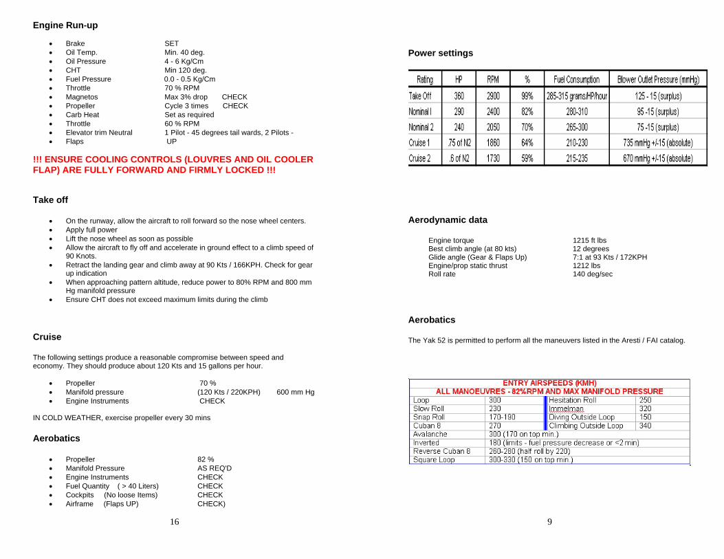
Power settings Oil Temp. Min. 40 deg. Oil Pressure 4 - 6 Kg/Cm
• CHT Min 120 deg. Fuel Pressure 0.0 - 0.5 Kg/Cm Throttle 70 % RPM Magnetos Max 3% drop CHECK Propeller Cycle 3 times CHECK Carb Heat Set as required Throttle 60 % RPM Elevator trim Neutral 1 Pilot - 45 degrees tail wards, 2 Pilots - Flaps UP
!!! ENSURE COOLING CONTROLS (LOUVRES AND OIL COOLER FLAP) ARE FULLY FORWARD AND FIRMLY LOCKED !!!
Take off
• Aerodynamic data On the runway, allow the aircraft to roll forward so the nose wheel centers.
Apply full power Lift the nose wheel as soon as possible Engine torque 1215 ft lbs Allow the aircraft to fly off and accelerate in ground effect to a climb speed of 90 Knots.
Best climb angle (at 80 kts) 12 degrees Glide angle (Gear & Flaps Up) 7:1 at 93 Kts / 172KPH
Retract the landing gear and climb away at 90 Kts / 166KPH. Check for gear up indication
Engine/prop static thrust 1212 lbs Roll rate 140 deg/sec
When approaching pattern altitude, reduce power to 80% RPM and 800 mm Hg manifold pressure
Ensure CHT does not exceed maximum limits during the climb
Aerobatics
Cruise The Yak 52 is permitted to perform all the maneuvers listed in the Aresti / FAI catalog. The following settings produce a reasonable compromise between speed and
economy. They should produce about 120 Kts and 15 gallons per hour.
• Propeller 70 % • Manifold pressure (120 Kts / 220KPH) 600 mm Hg
Engine Instruments CHECK IN COLD WEATHER, exercise propeller every 30 mins
Aerobatics
• Propeller 82 % Manifold Pressure AS REQ'D Engine Instruments CHECK Fuel Quantity ( > 40 Liters) CHECK Cockpits (No loose Items) CHECK
Airframe (Flaps UP) CHECK)

10
• • • • • •
•
• • • •
15
• •
•
•
• •• •
• • •
• •
•
• • •
Emergency Procedures
Engine failure If an engine failure occurs at takeoff before the first turn (after takeoff) is made:
• Establish the best glide speed (93 Kts / 172KPH) and trim to that speed. Retract the landing gear Operate fuel cut-off (Move rearwards) Switch off Mags, Battery and ignition.
Open cockpitLand straight ahead if possible, otherwise, make only shallow turns. If the failure occurs after the first turn or in the pattern turn towards the runway and execute a normal landing. Should the engine stop while inverted: • Half roll to erect flight
Establish and trim to the best glide speed (93 Kts / 172KPH) Set the throttle to one third open Turn the mechanical fuel pump 45 degrees left Pump fuel pressure up to 0.1 -> 0.2 Kg/M
NOTE ** An engine restart from inverted flight will use at least 1200 ft of altitude!
Low Oil pressure Check oil temperature. If increasing, land as soon as practicable otherwise attempt to cool the oil by reducing power, increasing airspeed and opening the cooling shutters.
Emergency landing in confined area If an emergency landing must be performed in a confined area, minimize the landing roll by landing with gear UP.
Low fuel pressure Turn the mechanical fuel pump 45 left and pump to provide fuel pressure then land as soon as possible.
Engine roughness Reduce power, establish and trim for best glide speed (93 Kts / 172KPH). If the roughness stops, carefully increase power so as to establish level flight. If the roughness continues, increase rpm to 72% to clear the spark plugs.
Turn on the Master switch and the Engine switch Turn the primer to the "SYSTEM" (left) position pump slowly until fuel pressure is indicated Turn the primer to the right, "CYLINDER" position and pump 5 strokes. Leave the pump in the OUT position. Switch ON: • Master switch
Generator Ignition
Engine InstrumentsLanding Gear lights
Lift the guard flap and press the starter button As the engine turns, turn the MAG switch to "1+2" When the engine fires, push the primer in to further prime the cylinders. Lock it when the engine is running Increase power slowly to 40 % rpm Check engine instruments for correct indications, especially oil pressure
Warm Start Same as cold start except:
• Set throttle further open, (About 1/2 way) Prime the cylinders no more than 2 strokes
Warming up Allow the engine to warm up until all temperature indications are in the Yellow or Green ranges of the instruments. If the outside air temperature is low, you may close the cooling louvers to speed up the warming process. Continue to monitor all engine instruments during the warm up period for signs of trouble While waiting for the engine to reach its proper temperature, turn on the required systems and Avionics and test as necessary.
Taxi Check
• Brakes CHECK Turn & Bank, Gyro CHECK Flaps operation CHECK Altimeter SET
To turn the aircraft on the ground, apply rudder pedal in the direction you wish to turn and squeeze the brake lever. This action diverts air pressure to the side towards which you have applied the rudder and causes the aircraft to turn in that direction. To stop the turn, apply opposite rudder and brakes.

14
• • • • • • • •
• • • • • • • •
• • • • • •
• • • • •
• •
•
11
• • • • •
• • • • • •
•
Before entering the cockpit Check the following items in the FRONT cockpit:
• Ensure no loose objects in the cockpit Check seat for damage Check condition of seat belts Check MAG switches to '0' Check starter button is covered by guard Check all switches OFF Check landing gear selector in DOWN position and latch engaged Set brakes ON Set main air supply to ON position (Fully counter clockwise)
In the REAR cockpit:
• Ignition switch set to "1st cockpit" (UP) MAGS set to "1+2" (Both) Gear control in neutral and locked Flap control in neutral and locked Instrument failure switches OFF (DOWN) rake override switch OFF
Parachute removedStraps secured and tied Canopy locked in closed position
After entering the cockpit
• Adjust rudder pedals for reach Fasten and check the seatbelts Connect the headset cord Ensure canopy slides freely and can be locked Check flight controls for freedom of movement Check elevator trim for freedom of movement Check clock reading. Wind and set if necessary
Cold Start
• Double check air supply is ON (Or you will have no brakes!) Set cooling controls fully forward Set prop to MAX RPM (Full forward) Set throttle to 1/3 open position Set fuel valve to OPEN (full forward) Set CARB HEAT to HOT (Full rearward position) if temperature is below freezing, otherwise fully forward Turn MAGS OFF ('0') Ensure that master switch is OFF (center position) and ignition switch is OFF (Down) Ground crew must pull propeller through at least 12 blades
If the roughness still persists, experiment with the power setting in order to find a combination of manifold pressure and rpm that minimizes the vibration and land as soon as possible.
Propeller Over-speed If the maximum permitted rpm is exceeded during takeoff, reduce rpm by means of the propeller control and continue the takeoff. In-flight fire
• Activate the fuel cut-off (Move rearwards) Establish and trim for the best glide speed (95 Kts / 109KPH) Side-slip if necessary, to help blow the flames away from the cockpit Perform an emergency landing If the fire continues unabated, bail out immediately. NOTE ** DO NOT INCREASE SPEED. It can considerably intensify the fire.
Emergency landing gear extension If it is not possible to extend the landing gear in the usual way, perform an emergency extension as follows:
• Check emergency air pressure is at least 10 Kg/cm Set landing gear lever to neutral in both cockpits Wait as long as fuel allows for air to exhaust Reduce speed to minimum (71 Kts / 131KPH) Open emergency gear release valve on the right side of the cockpit Check for green "Gear Down" light Close the emergency gear release valve only after completing the flight and shutting down the engine DO NOT ATTEMPT TO RAISE THE GEAR USING THE EMERGENCY SYSTEM
Landing with flaps up Landing without flaps is little different to a normal landing. It is only necessary to allow a little extra speed (90 Kts / 166KPH) and to bear in mind that the landing distance will be consequently increased
Radio failure

12
• • • • •
• • •
• • • •
13
•
• • • • • • • • • • • • • • • • • • • •
• • •
Check headphone plugs are secure Check "YKB" switch is ON Check volume control is at maximum Check correct frequency is selected Check back of POH for Light Gun Signals
Bailing out of the aircraft NOTE ** Leaving the aircraft at speeds greater than 110 Kts / 203KPH is most hazardous as is attempting to bail out at less than 500 ft altitude. The most reliable way to leave the aircraft is to roll inverted and exit at a low airspeed. From this attitude:
Bunch up you body as small as possible Release the harness and any back-up straps Push the stick forward and fall from the aircraft
If you have to bail out from upright flight:
• Release the seat belt
Lift the parachute out of the seat pan Stand up in the seat Roll out of the aircraft, head down in a somersault position If both seats are occupied, the front seat occupant should leave the aircraft first.
Landing with failed engine With gear and flaps retracted, the aircraft glides at a ratio of 7:1. With gear down, the ratio is 5:1. From these figures, the gliding distance may be determined. A speed of 88 Kt s / 162KPH will achieve the greatest distance in no wind but in a turn, 93 Kts / 172KPH will provide slightly less height loss. Gliding turns are best made at a 45 degree angle of bank.
CHECKLISTS
Preflight If the aircraft has not been flown in a week or more, the following extra procedures must be followed:
• Remove the lowest two spark plugs and clean. Remove the drain plugs in the three lowest inlet manifold tubes and allow any collected oil to drain.
Then:
Inspect the ground around the prop for loose items, gravel etc. Check Propeller for nicks Check cowl flaps (louvers) for correct operation Ensure oil radiator cover is removed Check landing gear struts. Should be about 4 or 5 inches extended Check fuselage for damage Check ground for oil leaks Check cowl latches are secure Check main landing gear security - tires - latch & indicator
Check flapsDrain fuel system Check rear fuselage for loose rivets and antennas Check control surfaces for freedom of movement Check cockpits for loose items Check canopy for cleanliness and cracks Check ailerons for freedom of movement Remove pitot cover & check static ports Check stall warning system (If fitted) Visually check fuel level Visually check oil level.
• MAX LEVEL:Normal flight 16 liters Aerobatic flight 10 liters MINIMUM level: 8 liters