wz-40 !!!!i orandum - safety · occupant compart. intrusion41mm roof dent none 40 mm roof dent...
TRANSCRIPT
!!!!IU.S. Departmentof TransportationFederal HighwayAdministration
WZ-40
orandum
Subject: INFORMATION: Crashworthy Work Zone TrafficControl Devices PO d Study
From: Frederick G. is@JProgram Manager
Date: J u n e 6 , 2000
Reply: to: HSA-1
To: Resource Center DirectorsDivision AdministratorsFederal Lands Highway Division Engineers
This memorandum finds three work zone traflic control devices acceptable for use in work zoneson the National Highway System (NHS). They were tested at the Texas Transportation Institute(TTI) as part of an FHWA pooled-fund study (Contract No. DTFH61-97-C-00064) under theprovisions of National Cooperative Highway Research Program (NCHRP) Report 350“Recommended Procedures for the Safety Performance Evaluation of Highway Features.” Thethree acceptable devices are:
Type III Perforated Steel Tubing Barricade (with sign as tested, or without)Illinois L-Channel Type III BarricadeCrosswind Portable Sign Support
A fourth device, the New Jersey DOT PVC Barricade with Sign Panel, was tested and failed. It isdescribed at the end of this memorandum
The FHWA guidance on crash testing of work zone traffic control devices is contained in twomemoranda. The first, dated July 25, 1997, titled “Information: Identifying Acceptable HighwaySafety Features,” established four categories of work zone devices: Category I devices were thoselightweight devices which could be self-certified by the vendor, Category II devices were otherlightweight devices which needed individual crash testing, Category III devices were barriers andother fixed or massive devices also needing crash testing, and Category IV devices were trailermounted lighted signs, arrow panels, etc. The second guidance memorandum was issued onAugust 28, 1998, and is titled “INFORMATION: Crash Tested Work Zone Traffic ControlDevices.” This later memorandum lists devices that are acceptable under Categories I, II, and III.For an up-to-date list of crash tested hardware see our web site athttp://safety.fhwa.dot.gov/roadside.
Drawings of the tested devices are attached. A brief description of the three devices follows:

2
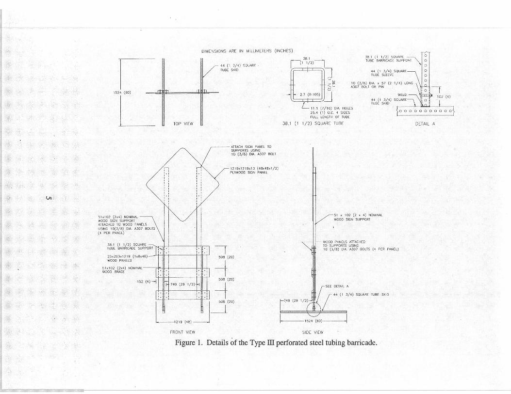
Type III Perforated Steel Tubing Barricade
The barricades were fabricated from perforated square steel tubing (PSST) with woodenhorizontal rails and had a 1219 mmx 1219 mmplywood sign panel (13 mm exterior BC)mounted at a height of 2134 mm AU PSST sections were 13 gage (2.4 mm wall) of A-36 steel.The skids were fabricated from 44 mm PSST, 1524 mm in length A 102 mm long stub of 44 mmPSST was welded to the top of each skid in the center with E6011 weld all around. The verticalsupports, of 38 mm PSST, were inserted into the stubs and secured with 10 mm (3/8- inch)diameter, 57 mm long A307 bolts or pins. The overall height of the barricade was 1524 mm
The 12 19 mm long horizontal rails were made of 25 mm x 203 mm No.2 white pine spaced508 mm apart. The No. 2 yellow pine vertical supports were placed 889 mm center to center.The wood rails were bolted to the vertical supports with four 10 mm diameter A307 bolts perrail. The horizontal rails were also bolted to two 5 1 mm x 102 mm wood vertical braces, one oneach side of the barricade outside of the vertical supports.
Inside the vertical braces were another set of 51 mm x 102 mm wood vertical supports for thesign panel. These, too, were attached to the barricade with four 10 mm A307 bolts per rail.Standard 10 mm washers were used when fastening the barricade rails and the sign panel inplace. Sandbags were added to the front and rear of each skid. The crash test is summarized inthe table following these descriptions.
Illinois L-Channel Type III Barricade
The skids and vertical supports of this barricade were fabricated from 50 mm x 50 mm x 5 mmA-36 steel L-channels or angles. The skids were 1524 mm long and the vertical supports werewelded to the skids 450 mm from the front. The vertical supports were spaced 8 14 mm center tocenter. The 1220 mm long horizontal rails were 25 mm x 254 mm white pine spaced 500 mmapart. These rails were bolted to the vertical supports using four 10 mm diameter A307 bolts perrail. Sandbags were added to the front and rear of each skid. The crash test is summarized in thetable following these descriptions.
Crosswind Portable Sign Support
The “Crosswind” model 606-EHD portable sign stand is manufactured by Lang ProductsInternational and is available commercially. The legs are 32 mm square steel tubing, 3 mm thickand each is 1830 mm long. When fully deployed the four legs create an X-footprint that is 1356mm wide and 2154 mm long. The four legs are secured by spring-loaded lock pins and 13 mmhardware. The brackets that join the legs at the base are made of 6 mm thick steel plates. A1200 mm x 1200 mm vinyl roll-up sign panel was mounted to the support at an extendedmounting height of 1520 mm from the ground to the bottom of the sign panel. The crash test issummarized in the table following these descriptions.

3
Crash Testing
Full-scale automobile testing was conducted on each of these three devices, Two stand-aloneexamples of each device were tested in tandem one head-on and the next placed six metersdownstream turned at 90 degrees, as called for in our guidance memoranda. The completedevices as tested are shown in the Attachment. The crash tests are summarized in the tablebelow:
Occupant Impact Speed 4.5 m/s 3.4 m/s 1.0 m/s
Vehicle crush Major dents Minor dents Minor dents
Occupant Compart. Intrusion 41mm roof dent None 40 mm roof dent
Windshield Damage Head-on Cracking No contact Minor cracking
Windshield Damage 90 Dee. Cracking No contact Minor cracking
All three tests resulted in minor to moderate denting to the bumpers, hoods, and roofs of the testvehicles. Windshield damage was limited to cracking, but not to the extent that the glass wasdeformed or that any holes were made through the glass. Also, the barricades did not showpotential for penetrating the occupant compartment. On the test of the sign stand the researchersnoted that the dent in the roof indicated a remote potential for occupant compartment intrusion,but FHWA considers this performance to be within allowable limits.
The results of this testing met the FHWA requirements and, therefore, the devices listed in thetable above and shown in Attachment 1 are acceptable for use as Test Level 3 devices on theNHS under the range of conditions tested, when proposed by a State.
4
Our acceptance is limited to the crashworthiness characteristics of the devices and does not covertheir structural features, nor conformity with the Manual on Uniform Traffic Control Devices.Potential users should ensure that the hardware furnished has essentially the same chemistry,mechanical properties, and geometry as those tested with successful results, and that they willmeet the crashworthiness requirements of FHWA and NCHRP Report 350. Any changes thatmay adversely influence the crashworthiness of the devices will require a new acceptance letter.To prevent misunderstanding by others, this letter of acceptance, designated as number WZ-40shall not be reproduced except in full.
Additional discussion of PSST Type III barricades:
Numerous tests have been run on Type III barricades using PSST as horizontal skids anduprights. Wood or plastic rail elements have been used in the mostly head-on tests, These tests,some of which are covered in our FHWA Acceptance Letter WZ-3 dated August 28, 1998, showacceptable performance. Some individuals have expressed concern that an end-on test was notconducted on this class of barricade. (New York State DOT ran an informal end on test in the1980’s and reported acceptable results.) The test above shows that the PSST Type III barricade iscrashworthy per Report 350 when struck head-on and at 90 degrees, at least when the horizontalbarricade rails are 1219 mm (4 feet) long. We now consider the barricade to be acceptable withor without the sign, however the vertical wood elements to the outside of the PSST uprights maybe necessary to ensure that the barricade structure remains intact during a crash
Longer rail elements are used on Type III barricades by many agencies. In the PSST test reportedabove, the occupant impact velocity was close to the maximum allowable limit of 5 m/s.Therefore, we cannot allow PSST Type III Barricade / Sign supports wider than the one tested..However, if the sign and its supports are not present, the PSST Type III barricade with rails up to2440 mm (8 feet) long will also be acceptable. We consider that the performance of thebarricade would be similarly acceptable if rigid polyolefin or other similar rigid plastic panelswere used for the horizontal rail elements, Frangible plastic rails may not be used as they mayseparate or fracture and penetrate the windshield.
Proprietary Devices:
The CrossWind sign stands are patented products and considered “proprietary.” The use ofproprietary work zone traffic control devices in Federal-aid projects is generally of a temporarynature. They are selected by the contractor for use as needed and removed upon completion ofthe project. Under such conditions they can be presumed to meet requirement “a” given belowfor the use of proprietary products on Federal-aid projects. On the other hand, if proprietarydevices are specified for use on Federal-aid projects, except exempt, non-NHS projects, they:(a) must be supplied through competitive bidding with equally suitable unpatented items;


COLLEGE STATION
FRONT VIEW SIDE VIEW
D E T A I L 1
S E C T I O N A - A
The Texas A&M University System
Figure 1. Details of the Illinois L-Channel Type Ill barricade.