wisdot bridge manual chapter 13 – pierson.dot.wi.gov/.../lrfd/bridgemanual/ch-13.pdf · omitting...
TRANSCRIPT

WisDOT Bridge Manual Chapter 13 – Piers
January 2015 13-1
Table of Contents
13.1 General ............................................................................................................................ 3
13.1.1 Pier Type and Configuration ..................................................................................... 3
13.1.2 Bottom of Footing Elevation ...................................................................................... 4
13.1.3 Pier Construction ...................................................................................................... 4
13.2 Pier Types ........................................................................................................................ 5
13.2.1 Multi-Column Piers ................................................................................................... 5
13.2.2 Pile Bents ................................................................................................................. 6
13.2.3 Pile Encased Piers ................................................................................................... 7
13.2.4 Solid Single Shaft / Hammerheads ........................................................................... 8
13.2.5 Aesthetics ................................................................................................................. 8
13.3 Location ........................................................................................................................... 9
13.4 Loads on Piers ............................................................................................................... 10
13.4.1 Dead Loads ............................................................................................................ 10
13.4.2 Live Loads .............................................................................................................. 10
13.4.3 Vehicular Braking Force ......................................................................................... 11
13.4.4 Wind Loads ............................................................................................................ 11
13.4.4.1 Wind Load on Superstructure .......................................................................... 12
13.4.4.2 Wind Load Applied Directly to Substructure .................................................... 13
13.4.4.3 Wind Load on Vehicles ................................................................................... 13
13.4.4.4 Vertical Wind Load .......................................................................................... 13
13.4.5 Uniform Temperature Forces .................................................................................. 13
13.4.6 Force of Stream Current ......................................................................................... 16
13.4.6.1 Longitudinal Force .......................................................................................... 16
13.4.6.2 Lateral Force ................................................................................................... 16
13.4.7 Buoyancy ................................................................................................................ 17
13.4.8 Ice .......................................................................................................................... 18
13.4.8.1 Force of Floating Ice and Drift ......................................................................... 18
13.4.8.2 Force Exerted by Expanding Ice Sheet ........................................................... 19
13.4.9 Centrifugal Force .................................................................................................... 20
13.4.10 Extreme Event Collision Loads ............................................................................. 20
13.5 Load Application............................................................................................................. 22

WisDOT Bridge Manual Chapter 13 – Piers
January 2015 13-2
13.5.1 Loading Combinations ............................................................................................ 22
13.5.2 Expansion Piers ...................................................................................................... 22
13.5.3 Fixed Piers ............................................................................................................. 23
13.6 Multi-Column Pier and Cap Design ................................................................................ 24
13.7 Hammerhead Pier Cap Design ....................................................................................... 25
13.7.1 Draw the Idealized Truss Model ............................................................................. 26
13.7.2 Solve for the Member Forces .................................................................................. 27
13.7.3 Check the Size of the Bearings ............................................................................... 28
13.7.4 Design Tension Tie Reinforcement ......................................................................... 29
13.7.5 Check the Compression Strut Capacity .................................................................. 30
13.7.6 Check the Tension Tie Anchorage .......................................................................... 33
13.7.7 Provide Crack Control Reinforcement ..................................................................... 33
13.8 General Pier Cap Information ......................................................................................... 34
13.9 Column / Shaft Design ................................................................................................... 36
13.10 Pile Bent and Pile Encased Pier Analysis ..................................................................... 38
13.11 Footing Design ............................................................................................................. 39
13.11.1 General Footing Considerations ........................................................................... 39
13.11.2 Isolated Spread Footings ...................................................................................... 40
13.11.3 Isolated Pile Footings ........................................................................................... 42
13.11.4 Continuous Footings ............................................................................................. 44
13.11.5 Seals and Cofferdams .......................................................................................... 45
13.12 Quantities ..................................................................................................................... 47
13.13 Appendix A – Pier Details ............................................................................................. 48
13.14 Appendix B – Pile Encased Pier Construction .............................................................. 50
13.15 Design Examples ......................................................................................................... 51

WisDOT Bridge Manual Chapter 13 – Piers
January 2015 13-3
13.1 General
Piers are an integral part of the load path between the superstructure and the foundation. Piers are designed to resist the vertical loads from the superstructure, as well as the horizontal superstructure loads not resisted by the abutments. The magnitude of the superstructure loads applied to each pier shall consider the configuration of the fixed and expansion bearings, the bearing types and the relative stiffness of all of the piers. The analysis to determine the horizontal loads applied at each pier must consider the entire system of piers and abutments and not just the individual pier. The piers shall also resist loads applied directly to them, such as wind loads, ice loads, water pressures and vehicle impact.
Bridges being designed with staged construction, whether new or rehabilitation, shall satisfy the requirements of LRFD (or LFD, if applicable) for each construction stage. Utilize the same load factors, resistance factors, load combinations, etc. as required for the final configuration, unless approved by Chief Structures Development Engineer at WisDOT.
WisDOT policy item:
At this time, evaluation and plan preparations for accommodating a noted allowance for a precast pier option as indicated in 7.1.4.1.2 is only required for I-39/90 Project bridges. All other locations statewide may consider providing a noted allowance for a precast option. Contact the Bureau of Structures Development Section for further guidance.
13.1.1 Pier Type and Configuration
Many factors are considered when selecting a pier type and configuration. The engineer should consider the superstructure type, the characteristics of the feature crossed, span lengths, bridge width, bearing type and width, skew, required vertical and horizontal clearance, required pier height, aesthetics and economy. For bridges over waterways, the pier location relative to the floodplain and scour sensitive regions shall also be considered.
The connection between the pier and superstructure is usually a fixed or expansion bearing which allows rotation in the longitudinal direction of the superstructure. This has the effect of eliminating longitudinal moment transfer between the superstructure and the pier. In rare cases when the pier is integral with the superstructure, this longitudinal rotation is restrained and moment transfer between the superstructure and the pier occurs. Pier types illustrated in the Standard Details shall be considered to be a pinned connection to the superstructure.
On grades greater than 2 percent, the superstructure tends to move downhill towards the abutment. The low end abutment should be designed as fixed and the expansion joint or joints placed on the uphill side or high end abutment. Consideration should also be given to fixing more piers than a typical bridge on a flat grade.

WisDOT Bridge Manual Chapter 13 – Piers
January 2015 13-4
13.1.2 Bottom of Footing Elevation
The bottom of footing elevation for piers outside of the floodplain is to be a minimum of 4’ below finished ground line unless the footings are founded on solid rock. This requirement is intended to place the bottom of the footing below the frost line.
A minimum thickness of 2’-0” shall be used for spread footings and 2’-6” for pile-supported footings. Spread footings are permitted in streams only if they are founded on rock. Pile cap footings are allowed above the ultimate scour depth elevation if the piling is designed assuming the full scour depth condition.
The bottom of footing elevation for pile cap footings in the floodplain is to be a minimum of 6’ below stable streambed elevation. Stable streambed elevation is the normal low streambed elevation at a given pier location when not under scour conditions. When a pile cap footing in the floodplain is placed on a concrete seal, the bottom of footing is to be a minimum of 4’ below stable streambed elevation. The bottom of concrete seal elevation is to be a minimum of 8’ below stable streambed elevation. These requirements are intended to guard against the effects of scour.
13.1.3 Pier Construction
Except for pile encased piers (see Standard for Pile Encased Pier) and seal concrete for footings, all footing and pier concrete shall be placed in the dry. Successful underwater concreting requires special concrete mixes, additives and placement procedures, and the risk of error is high. A major concern in underwater concreting is that the water in which the concrete is placed will wash away cement and sand, or mix with the concrete, and increase the water-to-cement ratio. It was previously believed that if the lower end of the tremie is kept immersed in concrete during a placement, then the new concrete flows under and is protected by previously placed concrete. However, tests performed at the University of California at Berkeley show that concrete exiting a tremie pipe may exhibit many different flow patterns exposing more concrete to water than expected. A layer of soft, weak and water-laden mortar called laitance may also form within the pour. Slump tests do not measure shear resistance, which is the best predictor of how concrete will flow after exiting a tremie pipe.
Footing excavation adjacent to railroad tracks which falls within the critical zone shown on Standard for Highway Over Railroad Design Requirements requires an approved shoring system. Excavation, shoring and cofferdam costs shall be considered when evaluating estimated costs for pier construction, where applicable. Erosion protection is required for all excavations.

WisDOT Bridge Manual Chapter 13 – Piers
January 2015 13-5
13.2 Pier Types
The pier types most frequently used in Wisconsin are:
• Multi-column piers (Standards for Multi-Columned Pier and for Multi-Columned Pier – Type 2)
• Pile bents (Standard for Pile Bent)
• Pile encased piers (Standard for Pile Encased Pier)
• Solid single shaft / hammerheads (Standards for Hammerhead Pier and for Hammerhead Pier – Type 2)
Design loads shall be calculated and applied to the pier in accordance with 13.4 and 13.5. The following sections discuss requirements specific to each of the four common pier types.
13.2.1 Multi-Column Piers
Multi-column piers, as shown in Standard for Multi-Columned Pier, are the most commonly used pier type for grade separation structures. Refer to 13.6 for analysis guidelines.
A minimum of three columns shall be provided to ensure redundancy should a vehicular collision occur. If the pier cap cantilevers over the outside columns, a square end treatment is preferred over a rounded end treatment for constructability. WisDOT has traditionally used round columns. Column spacing for this pier type is limited to a maximum of 25’.
Multi-column piers are also used for stream crossings. They are especially suitable where a long pier is required to provide support for a wide bridge or for a bridge with a severe skew angle.
Continuous or isolated footings may be specified for multi-column piers. The engineer should determine estimated costs for both footing configurations and choose the more economical configuration. Where the clear distance between isolated footings would be less than 4’-6”, a continuous footing shall be specified.
A variation of the multi-column pier in Standard for Multi-Columned Pier is produced by omitting the cap and placing a column under each girder. This detail has been used for steel girders with girder spacing greater than 12’. This configuration is treated as a series of single column piers. The engineer shall consider any additional forces that may be induced in the superstructure cross frames at the pier if the pier cap is eliminated. The pier cap may not be eliminated for piers in the floodplain, or for continuous slab structures which need the cap to facilitate replacement of the slab during future rehabilitation.
See Standard for Highway Over Railroad Design Requirements for further details on piers supporting bridges over railways.

WisDOT Bridge Manual Chapter 13 – Piers
January 2015 13-6
13.2.2 Pile Bents
Pile bents are most commonly used for small to intermediate stream crossings and are shown on the Standard for Pile Bent.
Pile bents shall not be used to support structures over roadways or railroads due to their susceptibility to severe damage should a vehicular collision occur.
For pile bents, pile sections shall be limited to 12¾” or 14” diameter cast-in-place reinforced concrete piles with steel shells spaced at a minimum center-to-center spacing of 3’. A minimum of five piles per pier shall be used on pile bents. When a satisfactory design cannot be developed with one of these pile sections at the minimum spacing, another pier type should be selected. The outside piles shall be battered 2” per foot, and the inside piles shall be driven vertically. WisDOT does not rely on the shell of CIP piles for capacity; therefore these piles are less of a concern for long term reduced capacity due to corrosion than steel H-piles. For that reason the BOS Development Chief must give approval for the use of steel H-piles in open pile bents.
Because of the minimum pile spacing, the superstructure type used with pile bents is generally limited to cast-in-place concrete slabs, prestressed girders and steel girders with spans under approx. 70’ and precast, prestressed box girders less than 21” in height.
To ensure that pile bents are capable of resisting the lateral forces resulting from floating ice and debris or expanding ice, the maximum distance from the top of the pier cap to the stable streambed elevation, including scour, is limited to:
• 15’ for 12¾” diameter piles (or 12” H-piles if exception is granted).
• 20’ for 14” diameter piles (or 14” H-piles if exception is granted).
Use of the pile values in Table 11.3-5 or Standard for Pile Details is valid for open pile bents due to the exposed portion of the pile being inspectable.
The minimum longitudinal reinforcing steel in cast-in-place piles with steel shells is 6-#7 bars in 12” piles and 8-#7 bars in 14” piles. The piles are designed as columns fixed from rotation in the plane of the pier at the top and at some point below streambed.
All bearings supporting a superstructure utilizing pile bents shall be fixed bearings or semi-expansion.
Pile bents shall meet the following criteria:
• If the water velocity, Q100, is greater than 7 ft/sec, the quantity of the 100-year flood shall be less than 12,000 ft3/sec.
• If the streambed consists of unstable material, the velocity of the 100-year flood shall not exceed 9 ft/sec.
WisDOT Bridge Manual Chapter 13 – Piers
January 2015 13-7
Pile bents may only be specified where the structure is located within Area 3, as shown in the Facilities Development Manual 13-1-15, Attachment 15.1 and where the piles are not exposed to water with characteristics that are likely to cause accelerated corrosion.
The minimum cap size shall be 3’ wide by 3’-6” deep and the piles shall be embedded into the cap a minimum of 2’-0.
13.2.3 Pile Encased Piers
Pile encased piers are similar to pile bents except that a concrete encasement wall surrounds the piles. They are most commonly used for small to intermediate stream crossings where a pile bent pier is not feasible. Pile encased piers are detailed on Standard for Pile Encased Pier.
An advantage of this pier type is that the concrete encasement wall provides greater resistance to lateral forces than a pile bent. Also the hydraulic characteristics of this pier type are superior to pile bents, resulting in a smoother flow and reducing the susceptibility of the pier to scour at high water velocities. Another advantage is that floating debris and ice are less likely to accumulate against a pile encased pier than between the piles of a pile bent. Debris and ice accumulation are detrimental because of the increased stream force they induce. In addition, debris and ice accumulation cause turbulence at the pile, which can have the effect of increasing the local scour potential.
Pile sections shall be limited to 10”, 12” or 14” steel HP piles, or 10¾”, 12¾” or 14” diameter cast-in-place concrete piles with steel shells. Minimum center-to-center spacing is 3’. Where difficult driving conditions are expected, oil field pipe may be specified in the design. A minimum of five piles per pier shall be used. When a satisfactory design cannot be developed with one of these pile sections at the minimum spacing, another pier type should be selected. The inside and outside piles shall be driven vertically.
Pile encased piers should not be used for normal water depths greater than 10’, since this is the maximum practical depth for setting formwork and placing the reinforcing steel. Total pier height shall be less than 25 feet.
All bearings supporting a superstructure utilizing pile encased piers shall be fixed bearings or semi-expansion.
The connection between the superstructure and the pier shall be designed to transmit the portion of the superstructure design loads assumed to be taken by the pier.
The concrete wall shall be a minimum of 2’-6” thick. The top 3’ of the wall is made wider if a larger bearing area is required. See Standard for Pile Encased Pier for details. The bottom of the wall shall be placed 2’ to 4’ below stable streambed elevation, depending upon stream velocities and frost depth.
The concrete in the encasement wall may be placed under water if the procedure detailed in 13.14 is followed.

WisDOT Bridge Manual Chapter 13 – Piers
January 2015 13-8
13.2.4 Solid Single Shaft / Hammerheads
Solid single shaft piers are used for all types of crossings and are detailed on Standards for Hammerhead Pier and for Hammerhead Pier – Type 2. The choice between using a multi-column pier and a solid single shaft pier is based on economics and aesthetics. For high level bridges, a solid single shaft pier is generally the most economical and attractive pier type available.
The massiveness of this pier type provides a large lateral load capacity to resist the somewhat unpredictable forces from floating ice, debris and expanding ice. They are suitable for use on major rivers adjacent to shipping channels without additional pier protection. When used adjacent to railroad tracks, crash walls are not required.
If a cofferdam is required and the upper portion of a single shaft pier extends over the cofferdam, an optional construction joint is provided 2’ above the normal water elevation. Since the cofferdam sheet piling is removed by extracting vertically, any overhead obstruction prevents removal and this optional construction joint allows the contractor to remove sheet piling before proceeding with construction of the overhanging portions of the pier.
A hammerhead pier shall not be used when the junction between the cap and the shaft would be less than the cap depth above normal water. Hammerhead piers are not considered aesthetically pleasing when the shaft exposure above water is not significant. A feasible alternative in this situation would be a wall type solid single shaft pier or a multi-column pier. On a wall type pier, both the sides and ends may be sloped if desired, and either a round, square or angled end treatment is acceptable. If placed in a waterway, a square end type is less desirable than a round or angled end.
13.2.5 Aesthetics
Refer to 13.13 for suggested alternative pier shapes. These shapes are currently being studied so no standard details are shown. It is desirable to standardize alternate shapes for efficiency and economy of construction. Use of these alternate pier shapes for aesthetics should be approved by the Chief Structures Development Engineer so that standard details can be developed.
Refer to Chapter 4 for additional information about aesthetics.

WisDOT Bridge Manual Chapter 13 – Piers
January 2015 13-9
13.3 Location
Piers shall be located to provide a minimum interference to flood flow. In general, place the piers parallel with the direction of flood flow. Make adequate provision for drift and ice by increasing span lengths and vertical clearances, and by selecting proper pier types. Special precautions against scour are required in unstable streambeds. Navigational clearance shall be considered when placing piers for bridges over navigable waterways. Coordination with the engineer performing the hydraulic analysis is required to ensure the design freeboard is met, the potential for scour is considered, the hydraulic opening is maintained and the flood elevations are not adversely affected upstream or downstream. Refer to Chapter 8 for further details.
In the case of railroad and highway separation structures, the spacing and location of piers and abutments is usually controlled by the minimum horizontal and vertical clearances required for the roadway or the railroad. Other factors such as utilities or environmental concerns may influence the location of the piers. Sight distance can impact the horizontal clearance required for bridges crossing roadways on horizontally curved alignments. Requirements for vertical and horizontal clearances are specified in Chapter 3 – Design Criteria. Crash wall requirements are provided on Standard for Highway Over Railroad Design Requirements.
Cost may also influence the number of piers, and therefore the number of spans, used in final design. During the planning stages, an analysis should be performed to determine the most economical configuration of span lengths versus number of piers that meet all of the bridge site criteria.

WisDOT Bridge Manual Chapter 13 – Piers
January 2015 13-10
13.4 Loads on Piers
The following loads shall be considered in the design of piers. Also see 13.5 for additional guidance regarding load application.
13.4.1 Dead Loads
The dead load forces, DC and DW, acting on the piers shall include reactions from the superstructure. DC dead loads include structural components and nonstructural attachments, and DW dead loads include wearing surfaces and utilities. The pier diaphragm weight may be applied through the girders. Different load factors are applied to each of these dead load types.
For a detailed discussion of the application of dead load, refer to 17.2.4.1.
13.4.2 Live Loads
The HL-93 live load shall be used for all new bridge designs and is placed in 12’-wide design lanes. If fewer lane loads are used than what the roadway width can accommodate, the loads shall be kept within their design lanes. The design lanes shall be positioned between the curbs, ignoring shoulders and medians, to maximize the effect being considered. Refer to 17.2.4.2 for a detailed description of the HL-93 live load. For pier design, particular attention should be given to the double truck load described in 17.2.4.2.4. This condition places two trucks, spaced a minimum of 50’ apart, within one design lane and will often govern the maximum vertical reaction at the pier.
WisDOT policy items:
A 10 foot design lane width may be used for the distribution of live loads to a pier cap.
The dynamic load allowance shall be applied to the live load for all pier elements located above the ground line per LRFD [3.6.2].
For girder type superstructures, the loads are transmitted to the pier through the girders. For pier design, simple beam distribution is used to distribute the live loads to the girders. The wheel and lane loads are therefore transversely distributed to the girders by the lever rule as opposed to the Distribution Factor Method specified in LRFD [4.6.2.2.2]. The lever rule linearly distributes a portion of the wheel load to a particular girder based upon the girder spacing and the distance from the girder to the wheel load. The skew of the structure is not considered when calculating these girder reactions. Refer to 17.2.10 for additional information about live load distribution to the substructure and to Figure 17.2-17 for application of the lever rule.
For slab type superstructures, the loads are assumed to be transmitted directly to the pier without any transverse distribution. This assumption is used even if the pier cap is not integral with the superstructure. The HL-93 live load is applied as concentrated wheel loads combined with a uniform lane load. The skew of the structure is considered when applying

WisDOT Bridge Manual Chapter 13 – Piers
January 2015 13-11
these loads to the cap. The lane width is then divided by the cosine of the skew angle, and the load is distributed over the new lane width along the pier centerline.
As a reminder, the live load force to the pier for a continuous bridge is based on the reaction, not the sum of the adjacent span shear values. A pier beneath non-continuous spans (at an expansion joint) uses the sum of the reactions from the adjacent spans.
13.4.3 Vehicular Braking Force
Vehicular braking force, BR, is specified in LRFD [3.6.4] and is taken as the greater of:
• 25% of the axle loads of the design truck
• 25% of the axle loads of the design tandem
• 5% of the design truck plus lane load
• 5% of the design tandem plus lane load
The loads applied are based on loading one-half the adjacent spans. Do not use a percentage of the live load reaction. All piers receive this load. It is assumed that the braking force will be less than the dead load times the bearing friction value and all force will be transmitted to the given pier. The tandem load, even though weighing less than the design truck, must be considered for shorter spans since not all of the axles of the design truck may be able to fit on the tributary bridge length.
This force represents the forces induced by vehicles braking and may act in all design lanes. The braking force shall assume that traffic is traveling in the same direction for all design lanes as the existing lanes may become unidirectional in the future. This force acts 6’ above the bridge deck, but the longitudinal component shall be applied at the bearings. It is not possible to transfer the bending moment of the longitudinal component acting above the bearings on typical bridge structures. The multiple presence factors given by LRFD [3.6.1.1.2] shall be considered. Per LRFD [3.6.2.1], the dynamic load allowance shall not be considered when calculating the vehicular braking force.
13.4.4 Wind Loads
WisDOT exception to AASHTO:
The design wind velocity, VDZ, from LRFD [3.8.1.1] shall be set to 100 mph for all bridge elevations.
In 13.4.4.1 and 13.4.4.2, the base wind pressure, PB, will not be modified based on the elevation of the bridge and shall be taken as:
BD PP =

WisDOT Bridge Manual Chapter 13 – Piers
January 2015 13-12
Where:
PD = Design wind pressure at all elevations (ksf)
Wind loads are divided into the following four types.
13.4.4.1 Wind Load on Superstructure
To determine WS, the base wind pressures, PB, presented in Table 13.4-1 shall be applied to the superstructure elements as specified in LRFD [3.8.1.2.2].
Wind Skew Angle (deg.)
Trusses, Columns and Arches
Girders
Lateral Load (ksf)
Longitudinal Load (ksf)
Lateral Load (ksf)
Longitudinal Load (ksf)
0 0.075 0.000 0.050 0.000 15 0.070 0.012 0.044 0.006 30 0.065 0.028 0.041 0.012 45 0.047 0.041 0.033 0.016 60 0.024 0.050 0.017 0.019
Table 13.4-1 Superstructure Base Wind Pressures
The wind skew angle shall be taken as measured from a perpendicular to the longitudinal axis. The wind direction used shall be that which produces the maximum force effects on the member. Transverse and longitudinal pressures shall be applied simultaneously. The longitudinal component shall be applied at the bearing elevation, and the transverse component shall be applied at its actual elevation.
WisDOT policy item:
The following conservative values for wind on superstructure, WS, may be used for all girder bridges:
● 0.05 ksf, transverse
● 0.012 ksf, longitudinal
Both forces shall be applied simultaneously. Do not apply to open rails or fences. Do apply this force to all parapets, including parapets located between the roadway and sidewalk if there is an open rail or fence on the edge of the sidewalk.

WisDOT Bridge Manual Chapter 13 – Piers
January 2015 13-13
13.4.4.2 Wind Load Applied Directly to Substructure
To determine WS for wind applied directly to substructures, the base wind pressure, PB, to be applied to the substructure units is 0.040 ksf as specified in LRFD [3.8.1.2.3]. This load can be resolved into components based on skew, or the following policy item can be followed:
WisDOT policy item:
The following values for wind applied directly to substructures, WS, may be used for all bridges:
● 0.040 ksf, transverse (along axis of substructure unit)
● 0.040 ksf, longitudinal (normal to axis of substructure unit)
Both forces shall be applied simultaneously.
13.4.4.3 Wind Load on Vehicles
As specified in LRFD [3.8.1.3] the wind force on vehicles, WL, is applied 6 ft. above the roadway. The longitudinal component shall be applied at the bearing elevation, and the transverse component shall be applied at its actual elevation.
WisDOT policy item:
The following values for wind on live load, WL, may be used for all bridges:
● 0.100 klf, transverse
● 0.040 klf, longitudinal
Both forces shall be applied simultaneously.
13.4.4.4 Vertical Wind Load
As specified in LRFD [3.8.2] an overturning vertical wind force, WS, shall be applied to limit states that do not involve wind on live load. A vertical upward wind force of 0.020 ksf times the out-to-out width of the bridge deck shall be considered a longitudinal line load. This lineal force shall be applied at the windward ¼ point of the deck, which causes the largest upward force at the windward fascia girder.
13.4.5 Uniform Temperature Forces
Temperature changes in the superstructure cause it to expand and contract along its longitudinal axis. These length changes induce forces in the substructure units based upon the fixity of the bearings, as well as the location and number of substructure units. The skew angle of the pier shall be considered when determining the temperature force components.

WisDOT Bridge Manual Chapter 13 – Piers
January 2015 13-14
In determining the temperature forces, TU, applied to each substructure unit, the entire bridge superstructure length between expansion joints is considered. In all cases, there is a neutral point on the superstructure which does not move due to temperature changes. All temperature movements will then emanate outwards or inwards from this neutral point. This point is determined by assuming a neutral point. The sum of the expansion forces and fixed pier forces on one side of the assumed neutral point is then equated to the sum of the expansion forces and fixed pier forces on the other side of the assumed neutral point. Maximum friction coefficients are assumed for expansion bearings on one side of the assumed neutral point and minimum coefficients are assumed on the other side to produce the greatest unbalanced force for the fixed pier(s) on one side of the assumed neutral point. The maximum and minimum coefficients are then reversed to produce the greatest unbalanced force for the pier(s) on the other side of the assumed neutral point. For semi-expansion abutments, the assumed minimum friction coefficient is 0.06 and the maximum is 0.10. For laminated elastomeric bearings, the force transmitted to the pier is the shear force generated in the bearing due to temperature movement. Example E27-1.8 illustrates the calculation of this force. Other expansion bearing values can be found in Chapter 27 – Bearings. When writing the equation to balance forces, one can set the distance from the fixed pier immediately to one side of the assumed neutral point as ‘X’ and the fixed pier immediately to the other side as (Span Length – ‘X’). This is illustrated in Figure 13.4-1.
Figure 13.4-1 Neutral Point Location with Multiple Fixed Piers
As used in Figure 13.4-1:
E = Column or shaft modulus of elasticity (ksi)
E F F E
Span 3Span 2Span 1X Span 2 - X
Neutral PointCase 1: DL x µmaxCase 2: DL x µmin
Case 1: DL x µminCase 2: DL x µmax
( )∑ ∑ µ+
−α=∑
α+∑ µ min33max xDL
h144X2SpanTEI3
h144TXEI3xDL:1Case
(Lt. Abutment) (Rt. Abutment)(Pier 1) (Pier 2)

WisDOT Bridge Manual Chapter 13 – Piers
January 2015 13-15
I = Column or shaft gross moment of inertia about longitudinal axis of the pier (in4)
α = Superstructure coefficient of thermal expansion (ft/ft/°F)
T = Temperature change of superstructure (°F)
μ = Coefficient of friction of the expansion bearing (dimensionless)
h = Column height (ft)
DL = Total girder dead load reaction at the bearing (kips)
X = Distance between the fixed pier and the neutral point (ft)
The temperature force on a single fixed pier in a bridge is the resultant of the unbalanced forces acting on the substructure units. Maximum friction coefficients are assumed for expansion bearings on one side of the pier and minimum coefficients are assumed on the other side to produce the greatest unbalanced force on the fixed pier.
The temperature changes in superstructure length are assumed to be along the longitudinal axis of the superstructure regardless of the substructure skew angle. This assumption is more valid for steel structures than for concrete structures.
The force on a column with a fixed bearing due to a temperature change in length of the superstructure is:
3h144TLEI3F α
=
Where:
L = Superstructure expansion length between neutral point and location being considered (ft)
F = Force per column applied at the bearing elevation (kips)
This force shall be resolved into components along both the longitudinal and transverse axes of the pier.
The values for computing temperature forces in Table 13.4-2 shall be used on Wisconsin bridges. Do not confuse this temperature change with the temperature range used for expansion joint design.
Reinforced Concrete Steel Temperature Change 45 °F 90 °F
Coefficient of Thermal Expansion 0.0000060/°F 0.0000065/°F

WisDOT Bridge Manual Chapter 13 – Piers
January 2015 13-16
Table 13.4-2 Temperature Expansion Values
Temperature forces on bridges with two or more fixed piers are based on the movement of the superstructure along its centerline. These forces are assumed to act normal and parallel to the longitudinal axis of the pier as resolved through the skew angle. The lateral restraint offered by the superstructure is usually ignored. Except in unusual cases, the larger stiffness generated by considering the transverse stiffness of skewed piers is ignored.
13.4.6 Force of Stream Current
The force of flowing water, WA, acting on piers is specified in LRFD [3.7.3]. This force acts in both the longitudinal and transverse directions.
13.4.6.1 Longitudinal Force
The longitudinal force is computed as follows:
000,1VC
p2
D=
Where:
p = Pressure of flowing water (ksf)
V = Water design velocity for the design flood in strength and service limit states and for the check flood in the extreme event limit state (ft/sec)
CD = Drag coefficient for piers (dimensionless), equal to 0.7 for semicircular-nosed piers, 1.4 for square-ended piers, 1.4 for debris lodged against the pier and 0.8 for wedged-nosed piers with nose angle of 90° or less
The longitudinal drag force shall be computed as the product of the longitudinal stream pressure and the projected exposed pier area.
13.4.6.2 Lateral Force
The lateral force is computed as follows:
000,1VCp
2D=
Where:
p = Lateral pressure of flowing water (ksf)

WisDOT Bridge Manual Chapter 13 – Piers
January 2015 13-17
CD = Lateral drag coefficient (dimensionless), as presented in Table 13.4-3
Angle Between the Flow Direction and the Pier’s Longitudinal Axis
CD
0° 0.0 5° 0.5
10° 0.7 20° 0.9
≥ 30° 1.0
Table 13.4-3 Lateral Drag Coefficient Values
The lateral drag force shall be computed as the product of lateral stream pressure and the projected exposed pier area. Use the water depth and velocity at flood stage with the force acting at one-half the water depth.
Normally the force of flowing water on piers does not govern the pier design.
13.4.7 Buoyancy
Buoyancy, a component of water load WA, is specified in LRFD [3.7.2] and is taken as the sum of the vertical components of buoyancy acting on all submerged components. The footings of piers in the floodplain are to be designed for uplift due to buoyancy.
Full hydrostatic pressure based on the water depth measured from the bottom of the footing is assumed to act on the bottom of the footing. The upward buoyant force equals the volume of concrete below the water surface times the unit weight of water. The effect of buoyancy on column design is usually ignored. Use high water elevation when analyzing the pier for over-turning. Use low water elevation to determine the maximum vertical load on the footing.
The submerged weight of the soil above the footing is used for calculating the vertical load on the footing. Typical values are presented in Table 13.4-4.
Submerged Unit Weight, γ (pcf)
Sand Sand & Gravel Silty Clay Clay Silt
Minimum (Loose) 50 60 40 30 25 Maximum (Dense) 85 95 85 70 70
Table 13.4-4 Submerged Unit Weights of Various Soils

WisDOT Bridge Manual Chapter 13 – Piers
January 2015 13-18
13.4.8 Ice
Forces from floating ice and expanding ice, IC, do not act on a pier at the same time. Consider each force separately when applying these design loads.
For all ice loads, investigate each site for existing conditions. If no data is available, use the following data as the minimum design criteria:
• Ice pressure = 32 ksf
• Minimum ice thickness = 12”
• Height on pier where force acts is at the 2-year high water elevation. If this value is not available, use the elevation located midway between the high and measured water elevations.
• Pier width is the projection of the pier perpendicular to stream flow.
Slender and flexible piers shall not be used in regions where ice forces are significant, unless approval is obtained from the WisDOT Bureau of Structures.
13.4.8.1 Force of Floating Ice and Drift
Ice forces on piers are caused by moving sheets or flows of ice striking the pier.
There is not an exact method for determining the floating ice force on a pier. The ice crushing strength primarily depends on the temperature and grain size of the ice. LRFD [3.9.2.1] sets the effective ice crushing strength at between 8 and 32 ksf.
The horizontal force caused by moving ice shall be taken as specified in LRFD [3.9.2.2], as follows:
ptwCFF ac ==
5.0
a )1w(t5C
+
=
Where:
p = Effective ice crushing strength (ksf)
t = Ice thickness (ft)
w = Pier width at level of ice action (ft)

WisDOT Bridge Manual Chapter 13 – Piers
January 2015 13-19
WisDOT policy item:
Since the angle of inclination of the pier nose with respect to the vertical is always less than or equal to 15° on standard piers in Wisconsin, the flexural ice failure mode does not need to be considered for these standard piers ( 0fb = ).
WisDOT policy item:
If the pier is approximately aligned with the direction of the ice flow, only the first design case as specified in LRFD [3.9.2.4] shall be investigated due to the unknowns associated with the friction angle defined in the second design case.
A longitudinal force equal to F shall be combined with a transverse force of 0.15F
Both the longitudinal and transverse forces act simultaneously at the pier nose.
If the pier is located such that its longitudinal axis is skewed to the direction of the ice flow, the ice force on the pier shall be applied to the projected pier width and resolved into components. In this condition, the transverse force to the longitudinal axis of the pier shall be a minimum of 20% of the total force.
WisDOT exception to AASHTO:
Based upon the pier geometry in the Standards, the ice loadings of LRFD [3.9.4] and LRFD [3.9.5] shall be ignored.
13.4.8.2 Force Exerted by Expanding Ice Sheet
Expansion of an ice sheet, resulting from a temperature rise after a cold wave, can develop considerable force against abutting structures. This force can result if the sheet is restrained between two adjacent bridge piers or between a bluff type shore and bridge pier. The force direction is therefore transverse to the direction of stream flow.
Force from ice sheets depends upon ice thickness, maximum rate of air-temperature rise, extent of restraint of ice and extent of exposure to solar radiation. In the absence of more precise information, estimate an ice thickness and use a force of 8.0 ksf.
It is not necessary to design all bridge piers for expanding ice. If one side of a pier is exposed to sunlight and the other side is in the shade along with the shore in the pier vicinity, consider the development of pressure from expanding ice. If the central part of the ice is exposed to the sun's radiation, consider the effect of solar energy, which causes the ice to expand.

WisDOT Bridge Manual Chapter 13 – Piers
January 2015 13-20
13.4.9 Centrifugal Force
Centrifugal force, CE, is specified in LRFD [3.6.3] and is included in the pier design for structures on horizontal curves. The lane load portion of the HL-93 loading is neglected in the computation of the centrifugal force.
The centrifugal force is taken as the product of the axle weights of the design truck or tandem and the factor, C, given by the following equation:
gRv
34C
2
=
Where:
V = Highway design speed (ft/sec)
g = Gravitational acceleration = 32.2 (ft/sec2)
R = Radius of curvature of travel lane (ft)
The multiple presence factors specified in LRFD [3.6.1.1.2] shall apply to centrifugal force.
Centrifugal force is assumed to act radially and horizontally 6’ above the roadway surface. The point 6’ above the roadway surface is measured from the centerline of roadway. The design speed may be determined from the Wisconsin Facilities Development Manual, Chapter 11. It is not necessary to consider the effect of superelevation when centrifugal force is used, because the centrifugal force application point considers superelevation.
13.4.10 Extreme Event Collision Loads
WisDOT policy item:
With regards to LRFD [3.6.5] and vehicular collision force, CT, protecting the pier and designing the pier for the 600 kip static force are each equally acceptable. The bridge design engineer should work with the roadway engineer to determine which alternative is preferred.

WisDOT Bridge Manual Chapter 13 – Piers
January 2015 13-21
WisDOT policy item:
Designs for bridge piers adjacent to roadways with a design speed ≤ 40 mph need not consider the provisions of LRFD [3.6.5].
If the design speed of a roadway adjacent to a pier is > 40 mph and the pier is not protected by a TL-5 barrier, embankment or adequate offset, the pier columns/shaft, only, shall be strengthened to comply with LRFD [3.6.5]. For a multi-column pier the minimum size column shall be 3x4 ft rectangular or 4 ft diameter (consider clearance issues and/or the wide cap required when using 4 ft diameter columns). Solid shaft and hammerhead pier shafts are considered adequately sized.
All multi-columned piers require a minimum of three columns. If a pier cap consists of two or more segments each segment may be supported by two columns. If a pier is constructed in stages, two columns may be used for the temporary condition.
The vertical reinforcement for the columns/shaft shall be the greater of what is required by design (not including the Extreme Event II loading) or a minimum of 1.0% of the gross concrete section (total cross section without deduction for rustications less than or equal to 1-1/2” deep) to address the collision force for the 3x4 ft rectangular and 4 ft diameter columns.
For the 3x4 ft rectangular columns, use double #5 stirrups spaced at 6” vertically as a minimum. For the 4 ft diameter columns, use #4 spiral reinforcement (smooth bars) spaced vertically at 6” as a minimum. Hammerhead pier shafts shall have, as a minimum, the horizontal reinforcement as shown on the Standards.
See Standard for Multi-Columned Pier with Rectangular Columns for an acceptable design to meet LRFD [3.6.5].
WisDOT exception to AASHTO:
The vessel collision load, CV, in LRFD [3.14] will not be applied to every navigable waterway of depths greater than 2’. For piers located in navigable waterways, the engineer shall contact the WisDOT project manager to determine if a vessel collision load is applicable.

WisDOT Bridge Manual Chapter 13 – Piers
January 2015 13-22
13.5 Load Application
When determining pier design forces, a thorough understanding of the load paths for each load is critical to arriving at loads that are reasonable per AASHTO LRFD. The assumptions associated with different pier, bearing and superstructure configurations are also important to understand. This section provides general guidelines for the application of forces to typical highway bridge piers.
13.5.1 Loading Combinations
Piers are designed for the Strength I, Strength III, Strength V and Extreme Event II load combinations as specified in LRFD [3.4.1]. Reinforced concrete pier components are also checked for the Service I load combination. Load factors for these load combinations are presented in Table 13.5-1. See 13.10 for loads applicable to pile bents and pile encased piers.
Load Combination
Limit State
Load Factor DC DW LL+IM
BR CE
WA WS WL FR TU CR SH
IC CT CV
Max. Min. Max. Min.
Strength I 1.25 0.90 1.50 0.65 1.75 1.00 0.00 0.00 1.00 0.50 0.00 Strength III 1.25 0.90 1.50 0.65 0.00 1.00 1.40 0.00 1.00 0.50 0.00 Strength V 1.25 0.90 1.50 0.65 1.35 1.00 0.40 1.00 1.00 0.50 0.00 Service I 1.00 1.00 1.00 1.00 1.00 1.00 0.30 1.00 1.00 1.00 0.00 Extreme Event II
1.25 0.90 1.50 0.65 0.50 1.00 0.00 0.00 1.00 0.00 1.00
Table 13.5-1 Load Factors
13.5.2 Expansion Piers
See 13.4 for additional guidance regarding the application of specific loads.
Transverse forces applied to expansion piers from the superstructure include loads from one-half of the adjacent span lengths, and are applied at the location of the transverse load.
For expansion bearings other than elastomeric, longitudinal forces are transmitted to expansion piers through friction in the bearings. These forces, other than temperature, are based on loading one-half of the adjacent span lengths, with the maximum being no greater than the maximum friction force (dead load times the maximum friction coefficient of a sliding bearing). See 27.2.2 to determine the bearing friction coefficient. The longitudinal forces are applied at the bearing elevation.
WisDOT Bridge Manual Chapter 13 – Piers
January 2015 13-23
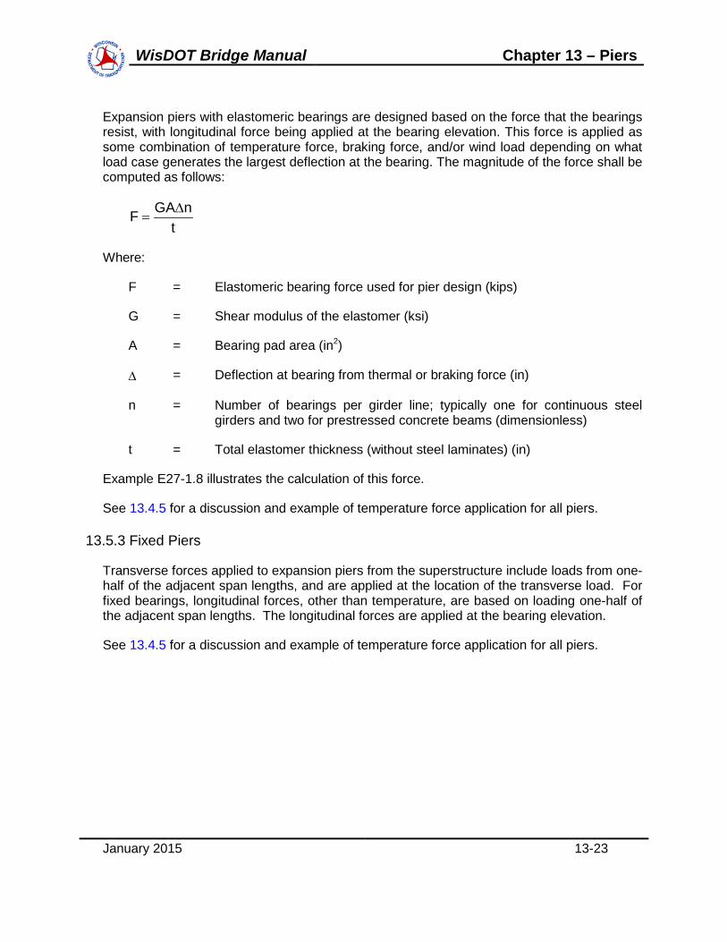
Expansion piers with elastomeric bearings are designed based on the force that the bearings resist, with longitudinal force being applied at the bearing elevation. This force is applied as some combination of temperature force, braking force, and/or wind load depending on what load case generates the largest deflection at the bearing. The magnitude of the force shall be computed as follows:
tnGAF ∆
=
Where:
F = Elastomeric bearing force used for pier design (kips)
G = Shear modulus of the elastomer (ksi)
A = Bearing pad area (in2)
∆ = Deflection at bearing from thermal or braking force (in)
n = Number of bearings per girder line; typically one for continuous steel girders and two for prestressed concrete beams (dimensionless)
t = Total elastomer thickness (without steel laminates) (in)
Example E27-1.8 illustrates the calculation of this force.
See 13.4.5 for a discussion and example of temperature force application for all piers.
13.5.3 Fixed Piers
Transverse forces applied to expansion piers from the superstructure include loads from one-half of the adjacent span lengths, and are applied at the location of the transverse load. For fixed bearings, longitudinal forces, other than temperature, are based on loading one-half of the adjacent span lengths. The longitudinal forces are applied at the bearing elevation.
See 13.4.5 for a discussion and example of temperature force application for all piers.

WisDOT Bridge Manual Chapter 13 – Piers
January 2015 13-24
13.6 Multi-Column Pier and Cap Design
WisDOT policy item:
Multi-column pier caps shall be designed using conventional beam theory.
The first step in the analysis of a pier frame is to determine the trial geometry of the frame components. The individual components of the frame must meet the minimum dimensions specified in 13.2.1 and as shown on the Standards. Each of the components should be sized for function, economy and aesthetics. Once a trial configuration is determined, analyze the frame and adjust the cap, columns and footings if necessary to accommodate the design loads.
When the length between the outer columns of a pier cap exceeds 65’, temperature and shrinkage should be considered in the design of the columns. These effects induce moments in the columns due to the expansion and contraction of the cap combined with the rigid connection between the cap and columns. A 0.5 factor is specified in the strength limit state for the temperature and shrinkage forces to account for the long-term column cracking that occurs. A full section modulus is then used for this multi-column pier analysis. Use an increase in temperature of +35 degrees F and a decrease of -45 degrees F. Shrinkage (0.0003 ft/ft) will offset the increased temperature force. For shrinkage, the keyed vertical construction joint as required on the Standard for Multi-Columned Pier, is to be considered effective in reducing the cap length. For all temperature forces, the entire length from exterior column to exterior column shall be used.
The maximum column spacing on pier frames is 25’. Column height is determined by the bearing elevations, the bottom of footing elevation and the required footing depth. The pier cap/column and column/footing interfaces are assumed to be rigid.
The pier is analyzed as a frame bent by any of the available analysis procedures considering sidesway of the frame due to the applied loading. The gross concrete areas of the components are used to compute their moments of inertia for analysis purposes. The effect of the reinforcing steel on the moment of inertia is neglected.
Vertical loads are applied to the pier through the superstructure. The vertical loads are varied to produce the maximum moments and shears at various positions throughout the structure in combination with the horizontal forces. The effect of length changes in the cap due to temperature is also considered in computing maximum moments and shears. All these forces produce several loading conditions on the structure which must be separated to get the maximum effect at each point in the structure. The maximum moments, shears and axial forces from the analysis routines are used to design the individual pier components. Moments at the face of column are used for pier cap design.
Skin reinforcement on the side of the cap, shall be determined as per LRFD [5.7.3.4]. This reinforcement shall not be included in any strength calculations.
See 13.1 and 13.2.1 for further requirements specific to this pier type.

WisDOT Bridge Manual Chapter 13 – Piers
January 2015 13-25
13.7 Hammerhead Pier Cap Design
WisDOT policy item:
Hammerhead pier caps shall be designed using the strut-and-tie method.
The strut-and-tie method is simply the creation of an internal truss system used to transfer the loads from the bearings through the pier cap to the column(s). This is accomplished through a series of concrete “struts” that resist compressive forces and steel “ties” that resist tensile forces. These struts and ties meet at nodes. See Figure 13.7-1 for a basic strut-and-tie model that depicts two bearing reactions transferred to two columns.
Figure 13.7-1 Basic Strut-and-Tie Elements
Strut-and-tie models are based on the following assumptions:
• The tension ties yield before the compressive struts crush.
• External forces are applied at nodes.
• Forces in the struts and ties are uniaxial.
• Equilibrium is maintained.
• Prestressing of the pier is treated as a load.
The generation of the model requires informed engineering judgment and is an iterative, graphical procedure. The following steps are recommended for a strut-and-tie pier cap design.
P
P P
Nodal Zone
P
Nodal Zone
Nodal Zone
Nodal Zone
Compressive Strut
Compressive Strut
Compressive Strut
Tension Tie

WisDOT Bridge Manual Chapter 13 – Piers
January 2015 13-26
13.7.1 Draw the Idealized Truss Model
This model will be based on the structure geometry and loading configuration. At a minimum, nodes shall be placed at each load and support point. Maintain angles of approximately 30° (minimum of 25o) to 60° (maximum of 65o) between truss members. An angle close to 45° should be used when possible. Figure 13.7-2 depicts an example hammerhead pier cap strut-and-tie model.
Figure 13.7-2 Example Hammerhead Pier Cap Strut-and-Tie Model
To begin, place nodes at the bearing locations and at the two column 1/3-points. In Figure 13.7-2, the minimum of nodes A, C, D, E and G are all placed at a bearing location, and nodes J and K are placed at the column 1/3-points. When drawing the truss model, the order of priority for forming compressive struts shall be the following:
AB C D E F
G
HI
J KL
M
R1 R2
ajd
a/2
d
T
C
Legend:
Pi = Vertical Load at BearingRi = Column Reactionφ = Angle from Vertical
CompressionTension
P1 P2 P3 P4 P5
φ
StirrupRegion 2
StirrupRegion 1
StirrupRegion 1
StirrupRegion 2

WisDOT Bridge Manual Chapter 13 – Piers
January 2015 13-27
1. Transfer the load directly to the column if the angle from vertical is less than 60°.
2. Transfer the load to a point directly beneath a bearing if the angle from vertical is between 30° and 60°.
3. Transfer the load at an approximately 45° angle from vertical and form a new node.
In Figure 13.7-2, the bearing load at node C is transferred directly to the column at node J since the angle formed by the compression strut C-J is less than 60°. The same occurs at strut E-K. However, the angle that would be formed by compression strut A-J to the column is not less than 60°, nor is the angle that would be formed by a strut A-I to beneath a bearing. Therefore, the load at node A is transferred at a 45° angle to node H by strut A-H. To maintain equilibrium at node H, the vertical tension tie B-H and the compression strut H-I are added.
Then, since the angle that would be formed by potential column strut B-J is not less than 60°, a check is made of the angle that would be formed by strut B-I. Since this angle is within the 30° to 60° range, compression strut B-I is added. To maintain equilibrium at node I, the vertical tension tie C-I and the compression strut I-J are added. This completes the basic strut-and-tie model for the left side of the cap. The geometric setup on the right side of the cap will be performed in the same manner as the left side.
The bearing load at node D, located above the column, is then distributed directly to the column as the angle from vertical of struts D-J and D-K are both less than 60°. Compression strut J-K must then be added to satisfy equilibrium at nodes J and K.
Vertically, the top chord nodes A, B, C, D, E, F and G shall be placed at the centroid of the tension steel. The bottom chord nodes H, I, J, K, L and M shall follow the taper of the pier cap and be placed at mid-height of the compression block, a/2, as shown in Figure 13.7-2.
The engineer should then make minor adjustments to the model using engineering judgment. In this particular model, this should be done with node H in order to make struts A-H and B-I parallel. The original 45° angle used to form strut A-H likely did not place node H halfway between nodes A and C. The angle of strut A-H should be adjusted so that node H is placed halfway between nodes A and C.
Another adjustment the engineer may want to consider would be placing four nodes above the column at 1/5-points as opposed to the conservative approach of the two column nodes shown in Figure 13.7-2 at 1/3-points. The four nodes would result in a decrease in the magnitude of the force in tension tie C-I. If the structure geometry were such that girder P2 were placed above the column or the angle from vertical for potential strut B-J were less than 60°, then the tension tie C-I would not be present.
13.7.2 Solve for the Member Forces
Determine the magnitude of the unknown forces in the internal tension ties and compression struts by transferring the known external forces, such as the bearing reactions, through the

WisDOT Bridge Manual Chapter 13 – Piers
January 2015 13-28
strut-and-tie model. To satisfy equilibrium, the sum of all vertical and horizontal forces acting at each node must equal zero.
13.7.3 Check the Size of the Bearings
Per LRFD [5.6.3.5], the concrete area supporting the bearing devices shall satisfy the following:
nu PP φ≤
Where:
φ = Resistance factor for bearing on concrete, equal to 0.70, as specified in LRFD [5.5.4.2] (dimensionless)
Pu = Bearing reaction from strength limit state (kips)
Pn = Nominal bearing resistance (kips)
For node regions bounded by compressive struts and bearing areas:
A'f85.0P cn =
For node regions anchoring a tension tie in one direction:
A'f75.0P cn =
For node regions anchoring tension ties in more than one direction:
A'f65.0P cn =
Where:
f’c = Specified concrete compressive strength (ksi)
A = Area under bearing device (in2)
WisDOT policy item:
WisDOT standard pier caps satisfy the bearing requirements of LRFD [5.7.5].

WisDOT Bridge Manual Chapter 13 – Piers
January 2015 13-29
13.7.4 Design Tension Tie Reinforcement
Tension ties shall be designed to resist the strength limit state force per LRFD [5.6.3.4.1]. For non-prestressed caps, the tension tie steel shall satisfy:
y
ust f
PA
φ≥
Where:
Ast = Total area of mild steel reinforcement in the tie (in2)
Pu = Tension tie force from strength limit state (kips)
φ = Resistance factor for tension on reinforced concrete, equal to 0.90, as specified in LRFD [5.5.4.2] (dimensionless)
fy = Yield strength of reinforcement (ksi)
Horizontal tension ties, such as ties A-B and E-F in Figure 13.7-2, are used to determine the longitudinal reinforcement required in the top of the pier cap. The maximum tension tie value should be used to calculate the top longitudinal reinforcement.
Vertical tension ties, such as ties B-H and C-I, are used to determine the vertical stirrup requirements in the cap. Similar to traditional shear design, two stirrup legs shall be accounted for when computing Ast. In Figure 13.7-2, the number of stirrups, n, necessary to provide the Ast required for tie B-H shall be spread out across Stirrup Region 2. The length limits of Stirrup Region 2 are from the midpoint between nodes A and B to the midpoint between nodes B and C. When vertical ties are located adjacent to columns, such as with tie C-I, the stirrup region extends to the column face. Therefore, the length limits of Stirrup Region 1 are from the column face to the midpoint between nodes B and C. The stirrup spacing shall then be determined by the following equation:
nLsmax =
Where:
smax = Maximum allowable stirrup spacing (in)
L = Length of stirrup region (in)
n = Number of stirrups required to satisfy the Ast required to resist the vertical tension tie force

WisDOT Bridge Manual Chapter 13 – Piers
January 2015 13-30
Skin reinforcement on the side of the cap, shall be determined as per LRFD [5.7.3.4]. This reinforcement shall not be included in any strength calculations.
13.7.5 Check the Compression Strut Capacity
Compression struts shall be designed to resist the strength limit state force per LRFD [5.6.3.3]. The resistance of an unreinforced compression strut shall be taken as:
ucscur PAfP ≥φ=
Where:
Pr = Factored resistance of compression strut (kips)
Pu = Compression strut force from strength limit state (kips)
φ = Resistance factor for compression in strut-and-tie models, equal to 0.70, as specified in LRFD [5.5.4.2] (dimensionless)
fcu = Limiting compressive stress (ksi)
Acs = Effective cross-sectional area of strut (in2)
The limiting compressive stress shall be given by:
c1
ccu 'f85.0
1708.0'f
f ≤ε+
=
In which:
( ) s2
ss1 cot002.0 α+ε+ε=ε
Where:
εs = Concrete tensile strain in the direction of the tension tie at the strength limit state (in/in)
αs = Smallest angle between the compression strut and the adjoining tension ties (°)
f’c = Specified compressive strength (ksi)
The concrete tensile strain is given by:
sst
us EA
P=ε

WisDOT Bridge Manual Chapter 13 – Piers
January 2015 13-31
Where:
Es = Modulus of elasticity of steel, taken as 29,000 (ksi)
The cross-sectional area of the strut, Acs, is determined by considering both the available concrete area and the anchorage conditions at the end of the strut. Figure 13.7-3, Figure 13.7-4 and Figure 13.7-5 illustrate the computation of Acs.
Figure 13.7-3 Strut Anchored by Tension Reinforcement Only
La
Lasinθs
θs
s
dba
A
ASection A-A
dba
≤6dba ≤6dba
≤6dba≤6dba

WisDOT Bridge Manual Chapter 13 – Piers
January 2015 13-32
Figure 13.7-4 Strut Anchored by Bearing and Tension Reinforcement
Figure 13.7-5 Strut Anchored by Bearing and Strut
0.5 ha
Lb
6db
ha
θs
Lbsinθs+hacosθs
Lb
hsθs
Lbsinθs+hscosθs

WisDOT Bridge Manual Chapter 13 – Piers
January 2015 13-33
In Figure 13.7-3, the strut area is influenced by the stirrup spacing, s, as well as the diameter of the longitudinal tension steel, dba. In Figure 13.7-4, the strut area is influenced by the bearing dimensions, Lb, in both directions, as well as the location of the center of gravity of the longitudinal tension steel, 0.5ha. In Figure 13.7-5, the strut area is influenced by the bearing dimensions, Lb, in both directions, as well as the height of the compression strut, hs. The value of hs shall be taken as equal to “a” as shown in Figure 13.7-2. The strut area in each of the three previous figures depends upon the angle of the strut with respect to the horizontal, θs.
If the initial strut width is inadequate to develop the required resistance, the engineer should increase the bearing block size.
13.7.6 Check the Tension Tie Anchorage
Tension ties shall be anchored to the nodal zones by either specified embedment length or hooks so that the tension force may be transferred to the nodal zone. As specified in LRFD [5.6.3.4], the tie reinforcement shall be fully developed at the inner face of the nodal zone. In Figure 13.7-4, this location is given by the edge of the bearing where θs is shown.
13.7.7 Provide Crack Control Reinforcement
Pier caps designed using the strut-and-tie method shall contain an orthogonal grid of reinforcing bars near each face in accordance with LRFD [5.6.3.6]. This reinforcement will control crack widths and ensure a minimum ductility. The ratio of reinforcement area to gross concrete area shall not be less than 0.003 in both directions. Maximum bar spacing shall not exceed 12”. The crack control steel, when located within the tension tie, may be considered as part of the tension tie reinforcement.

WisDOT Bridge Manual Chapter 13 – Piers
January 2015 13-34
13.8 General Pier Cap Information
The minimum cap dimension to be used is 3’ deep by 2’-6” wide, with the exception that a 2’-6” deep section may be used for caps under slab structures. If a larger cap is needed, use 6” increments to increase the size. The multi-column cap width shall be a minimum of 1 1/2" wider than the column on each side to facilitate construction forming. The pier cap length shall extend a minimum of 2’ transversely beyond the centerline of bearing and centerline of girder intersection.
On continuous slab structures, the moment and shear forces are proportional between the transverse slab section and the cap by the ratio of their moments of inertia. The effective slab width assumed for the transverse beam is the minimum of 1/2 the center-to-center column spacing or 8.0’.
slabcap
captotalcap II
IMM
+=
Where:
Mcap = Cap moment (kip-ft)
Mtotal = Total moment (kip-ft)
Icap = Moment of inertia of pier cap (in4)
Islab = Moment of inertia of slab (in4)
The concrete slab is to extend beyond the edge of pier cap as shown on Standards for Continuous Haunched Slab and for Continuous Flat Slab. If the cap is rounded, measure from a line tangent to the pier cap end and parallel to the edge of the deck.
Reinforcement bars are placed straight in the pier cap. Determine bar cutoff points on wide caps. If the pier cap is cantilevered over exterior columns, the top negative bar steel may be bent down at the ends to ensure development of this primary reinforcement.
Do not place shear stirrups closer than 4” on centers. Generally only double stirrups are used, but triple stirrups may be used to increase the spacing. If these methods do not work, increase the cap size. Stirrups are generally not placed over the columns. The first stirrup is placed one-half of the stirrup spacing from the edge of the column into the span.
The cap-to-column connection is made by extending the column reinforcement straight into the cap the necessary development length. Stirrup details and bar details at the end of the cap are shown on Standard for Multi-Columned Pier.
Crack control, as defined in LRFD [5.7.3.4] shall be considered for pier caps. Class 2 exposure condition exposure factors shall only be used when concern regarding corrosion

WisDOT Bridge Manual Chapter 13 – Piers
January 2015 13-35
(i.e., pier caps located below expansion joints, pier caps subject to intermittent moisture above waterways, etc.) or significant aesthetic appearance of the pier cap is present.

WisDOT Bridge Manual Chapter 13 – Piers
January 2015 13-36
13.9 Column / Shaft Design
See 13.4.10 for minimum shaft design requirements regarding the Extreme Event II collision load of LRFD [3.6.5].
Use an accepted analysis procedure to determine the axial load as well as the longitudinal and transverse moments acting on the column. These forces are generally largest at the top and bottom of the column. Apply the load factors for each applicable limit state. The load factors should correspond to the gross moment of inertia. Load factors vary for the gross moment of inertia versus the cracked moment as defined in LRFD [3.4.1] for γTU, γCR, γSH. Choose the controlling load combinations for the column design.
Columns that are part of a pier frame have transverse moments induced by frame action from vertical loads, wind loads on the superstructure and substructure, wind loads on live load, thermal forces and centrifugal forces. If applicable, the load combination for Extreme Event II must be considered. Longitudinal moments are produced by the above forces, as well as the braking force. These forces are resolved through the skew angle of the pier to act transversely and longitudinally to the pier frame. Longitudinal forces are divided equally among the columns.
Wisconsin uses tied columns following the procedures of LRFD [5.7.4]. The minimum allowable column size is 2’-6” in diameter. The minimum steel bar area is as specified in LRFD [5.7.4.2]. For piers not requiring a certain percentage of reinforcement as per 13.4.10 to satisfy LRFD [3.6.5] for vehicular collision load, a reduced effective area of reinforcement may be used when the cross-section is larger than that required to resist the applied loading.
The computed column moments are to consider moment magnification factors for slenderness effects as specified in LRFD [5.7.4.3]. Values for the effective length factor, K, are as follows:
• 1.2 for longitudinal moments with a fixed seat supporting prestressed concrete girders
• 2.1 for longitudinal moments with a fixed seat supporting steel girders and all expansion bearings
• 1.0 for all transverse moments
The computed moments are multiplied by the moment magnification factors, if applicable, and the column is designed for the combined effects of axial load and bending. According to LRFD [5.7.4.1] all force effects, including magnified moments, shall be transferred to adjacent components. The design resistance under combined axial load and bending is based on stress-strain compatibility. A computer program is recommended for determining the column’s resistance to the limit state loads.
As a minimum, the column shall provide the steel shown on the Pier Standards.
On large river crossings, it may be necessary to protect the piers from damage. Dolphins may be provided.

WisDOT Bridge Manual Chapter 13 – Piers
January 2015 13-37
The column-to-cap connection is designed as a rigid joint considering axial and bending stresses. Column steel is run through the joint into the cap to develop the compressive stresses or the tensile steel stresses at the joint.
In general, the column-to-footing connection is also designed as a rigid joint. The bar steel from the column is generally terminated at the top of the footing. Dowel bars placed in the footing are used to transfer the steel stress between the footing and the column.
Crack control, as defined in LRFD [5.7.3.4] shall be considered for pier columns. All pier columns shall be designed using a Class 2 exposure condition exposure factor.

WisDOT Bridge Manual Chapter 13 – Piers
January 2015 13-38
13.10 Pile Bent and Pile Encased Pier Analysis
WisDOT policy item:
Only the Strength I limit state need be utilized for determining the pile configuration required for open pile bents and pile encased piers. Longitudinal forces are not considered due to fixed or semi-expansion abutments being required for these pier types.
The distribution of dead load to the pile bents and pile encased piers is in accordance with 17.2.9. Live load is distributed according to 17.2.10.
WisDOT policy item:
Dynamic load allowance, IM, is included for determining the pile loads in pile bents, but not for piling in pile encased piers.
The pile force in the outermost, controlling pile is equal to:
Pn= SM
nF
+
Where:
F = Total factored vertical load (kips)
n = Number of piles
M = Total factored moment about pile group centroid (kip-ft)
S = Section modulus of pile group (ft3), equal to:
∑cd2
In which:
d = Distance of pile from pile group centroid
c = Distance from outermost pile to pile group centroid
See Standard for Pile Bent for details. See Standard for Pile Encased Pier for details.

WisDOT Bridge Manual Chapter 13 – Piers
January 2015 13-39
13.11 Footing Design
13.11.1 General Footing Considerations
There are typical concepts to consider when designing and detailing both spread footings and pile footings.
For multi-columned piers:
• Each footing for a given pier should be the same dimension along the length of the bridge.
• Each footing for a given pier should be the same thickness.
• Footings within a given pier need not be the same width.
• Footings within a given pier may have variable reinforcement.
• Footings within a given pier may have a different number of piles. Exterior footings should only have fewer piles than an interior footing if the bridge is unlikely to be widened in the future. An appropriate cap span layout will usually lend itself to similar footing/pile configurations.
• Heavier piles, especially if primarily end bearing piles, can be more economical.
For hammerhead piers:
• Make as many seals the same size as reasonable to facilitate cofferdam re-use.
• Seal thickness can vary from pier to pier.
• Footing dimensions, reinforcement and pile configuration can vary from pier to pier.
• Heavier piles, especially if primarily end bearing piles, can be more economical.
WisDOT exception to AASHTO:
Crack control, as defined in LRFD [5.7.3.4] shall not be considered for pier isolated spread footings, isolated pile footings and continuous footings.
Shrinkage and temperature reinforcement, as defined in LRFD [5.10.8] shall not be considered for side faces of any buried footings.

WisDOT Bridge Manual Chapter 13 – Piers
January 2015 13-40
13.11.2 Isolated Spread Footings
WisDOT policy item:
Spread footings are designed using LRFD strength limit state loads and resistance for moment and shear as specified in LRFD [5.13.3]. The foundation bearing capacity, used to dimension the footing’s length and width, shall be determined using 4th Edition of the AASHTO LRFD Bridge Design Specifications for Highway Bridges.
The spread footing is proportioned so that the foundation bearing capacity is not exceeded. The following steps are used to design spread footings:
1. Minimum depth of spread footings is 2’. Depth is generally determined from shear strength requirements. Shear reinforcement is not used.
2. A maximum of 25% of the footing area is allowed to act in uplift (or nonbearing). When part of a footing is in uplift, its section properties for analysis are based only on the portion of the footing that is in compression (or bearing). When determining the percent of a footing in uplift, use the Service Load Design method.
3. Soil weight on footings is based only on the soil directly above the footing.
4. The minimum depth for frost protection from top of ground to bottom of footing is 4’.
5. Spread footings on seals are designed by either of the following methods:
a. The footing is proportioned so the pressure between the bottom of the footing and the top of the seal does not exceed the foundation bearing capacity and not more than 25% of the footing area is in uplift.
b. The seal is proportioned so that pressure at the bottom of the seal does not exceed the foundation bearing capacity and the area in uplift between the footing and the seal does not exceed 25%.
6. The spread footing’s reinforcing steel is determined from the flexural requirements of LRFD [5.7.3]. The design moment is determined from the volume of the pressure diagram under the footing which acts outside of the section being considered. The weight of the footing and the soil above the footing is used to reduce the bending moment.
7. The negative moment which results if a portion of the footing area is in uplift is ignored. No negative reinforcing steel is used in spread footings.
8. Shear resistance is determined by the following two methods:
a. Two-way action

WisDOT Bridge Manual Chapter 13 – Piers
January 2015 13-41
The volume of the pressure diagram on the footing area outside the critical perimeter lines (placed at a distance d/2 from the face of the column, where d equals the effective footing depth) determines the shear force. The shear resistance is influenced by the concrete strength, the footing depth and the critical perimeter length. The critical perimeter length is 2 (L + d + W + d) for rectangular columns and π (2R + d) for round columns, where R is the column radius and d is the effective footing depth. The critical perimeter location for spread footings with rectangular columns is illustrated in Figure 13.11-1.
Figure 13.11-1 Critical Perimeter Location for Spread Footings
b. One-way action
The volume of the pressure diagram on the area enclosed by the footing edges and a line placed at a distance "d" from the face of the column determines the shear force. The shear resistance is influenced by the concrete strength, the footing depth and the entire footing width or length. The shear location for one-way action is illustrated in Figure 13.11-2.

WisDOT Bridge Manual Chapter 13 – Piers
January 2015 13-42
Figure 13.11-2
Shear Location for One-Way Action The footing weight and the soil above the areas are used to reduce the shear force.
9. The bottom layer of reinforcing steel is placed 3” clear from the bottom of the footing.
10. If adjacent edges of isolated footings are closer than 4’-6”, a continuous footing shall be used.
13.11.3 Isolated Pile Footings
WisDOT policy item:
Pile footings are designed using LRFD strength limit state loads and resistance for moment and shear as specified in LRFD [5.13.3]. The pile design shall use LRFD strength limit state loads to compare to the factored axial compression resistance specified in Table 11.3-5.
The nominal geotechnical pile resistance shall be provided in the Site Investigation Report. The engineer shall then apply the appropriate resistance factor from Table 11.3.1 to the nominal resistance to determine the factored pile resistance. The footing is proportioned so that when it is loaded with the strength limit state loads, the factored pile resistance is not exceeded.
The following steps are used to design pile-supported footings:
1. The minimum depth of pile footing is 2’-6”. The minimum pile embedment is 6”. See 13.2.2 for additional information about pile footings used for pile bents.
2. Pile footings in uplift are usually designed by method (a) stated below. However, method (b) may be used if there is a substantial cost reduction.

WisDOT Bridge Manual Chapter 13 – Piers
January 2015 13-43
a. Over one-half of the piles in the footings must be in compression for the Strength limit states. The section properties used in analysis are based only on the piles in compression. Pile and footing (pile cap) design is based on the Strength limit states. Service limit states require check for overall stability; however a check of crack control is not required per 13.11. The 600 kip collision load need not be checked per 13.4.10.
b. Piles may be designed for upward forces provided an anchorage device, sufficient to transfer the load, is provided at the top of the pile. Provide reinforcing steel to resist the tension stresses at the top of the footing.
3. Same as spread footing.
4. Same as spread footing.
5. The minimum number of piles per footing is four.
6. Pile footings on seals are analyzed above the seal. The only effect of the seal is to reduce the pile resistance above the seal by the portion of the seal weight carried by each pile.
7. If no seal is required but a cofferdam is required, design the piles to use the minimum required batter. This reduces the cofferdam size necessary to clear the battered piles since all piles extend above water to the pile driver during driving.
8. The pile footing reinforcing steel is determined from the flexural requirements of LRFD [5.7.3]. The design moment and shear are determined from the force of the piles which act outside of the section being considered. The weight of the footing and the soil above the footing are used to reduce the magnitude of the bending moment and shear force.
9. Shear resistance is determined by the following two methods:
a. Two-way action
The summation of the pile forces outside the critical perimeter lines placed at a distance d/2 from the face of the column (where d equals the effective footing depth) determines the shear force. The shear resistance is influenced by the concrete strength, the footing depth and the critical perimeter length. The critical perimeter length is 2 (L + d + W + d) for rectangular columns and π(2R + d) for round columns. The critical perimeter location for pile footings with rectangular columns is illustrated in Figure 13.11-3.

WisDOT Bridge Manual Chapter 13 – Piers
January 2015 13-44
Figure 13.11-3
Critical Perimeter Location for Pile Footings
If the center of a pile falls on a line, then one-half of the pile force is assumed to act on each side of the line.
b. One-way action
The summation of the pile forces located within the area enclosed by the footing edges and a line at distance "d" from the face of the column determines the shear force, as illustrated in Figure 13.11-2. The shear resistance is influenced by the concrete strength, the footing depth and the entire footing width or length. If the center of a pile falls on a line, then one-half of the pile force is assumed to act on each side of the line.
10. The weight of the footing and soil above the areas is used to reduce the shear force.
11. The bottom layer of reinforcing steel is placed directly on top of the piles.
13.11.4 Continuous Footings
Continuous footings are used in pier frames of two or more columns when the use of isolated footings would result in a distance of less than 4’-6” between edges of adjacent footings. They are designed for the moments and shears produced by the frame action of the pier and the soil pressure under the footing.
The soil pressure or pile load under the footing is assumed to be uniform. The soil pressures or pile loads are generally computed only from the vertical column loads along with the soil and footing dead load. The moments at the base of the column are ignored for soil or pile loads.

WisDOT Bridge Manual Chapter 13 – Piers
January 2015 13-45
To prevent unequal settlement, proportion the continuous footing so that soil pressures or pile loads are constant for Service I load combination. The footing should be kept relatively stiff between columns to prevent upward footing deflections which cause excessive soil or pile loads under the columns.
13.11.5 Seals and Cofferdams
A seal is a mat of unreinforced concrete poured under water inside the cofferdam or sheet piling. The seal is designed to withstand the hydrostatic pressure on its bottom when the water above it is removed. Dewatering the cofferdam allows cutting of piles, placement of reinforcing steel and pouring of the footing in a dry environment.
Seals are required for all piers founded on spread or pile footings that are too far below normal water to pour the footing in the dry, which ensures properly consolidated concrete. This criteria is very important for tall piers.
The hydrostatic pressure under the seal is resisted by the seal weight, the friction between the seal perimeter and the cofferdam walls, and friction between seal and piles for pile footings. The friction values used for the seal design are considered using the service limit state. To compute the capacity of piles in uplift, refer to Chapter 11. Values for bond on piles and sheet piling are presented in Table 13.11-1.
Application Value of Bond Bond on Piles 10 psi
Bond on Sheet Piling 2 psi applied to [ (Seal Depth - 2’) x Seal Perimeter ]
Table 13.11-1 Bond on Piles and Sheet Piling
Lateral forces from stream flow pressure are resisted by the penetration of the sheet piling below the streambed elevation and by the bracing inside the cofferdam. The cofferdam design shall be the responsibility of the contractor. When seals for spread footings are founded on rock, the weight of the seal is used to counterbalance the lateral stream flow pressure.
The downstream side of the cofferdam should be keyed into rock deep enough or backfilled enough to resist the lateral stream flow pressure. To provide a factor of safety, the cofferdam weight (sheet piling and bracing) is ignored in the analysis. The design stream flow velocity is based on the flow at the site at the time of construction but need not exceed 75% of the 100-year velocity. The force is calculated as per 13.4.6. If a stream velocity higher than design occurs, the contractor may add water to the cofferdam to improve stability. The extra water weight above the seal adds additional overturning resistance and also increases lateral resistance from additional friction forces at the bottom of the seal.
A rule of thumb for seal thickness is 0.40H for spread footings and 0.25H for pile footings, where H is the water depth from bottom of seal to top of water. The 2-year high water elevation, if available, should be used as the water elevation. The assumed water elevation

WisDOT Bridge Manual Chapter 13 – Piers
January 2015 13-46
used to determine the seal thickness should be noted on the plans. The minimum seal size is 1’-6” larger than the footing size on all sides. See Standard for Hammerhead Pier for additional guidance regarding the sizing of the seal.
Example: Determine the seal thickness for a 9’ x 12’ footing with 12-12” diameter piles. Uplift capacity of one pile equals 10 kips. The water depth to the top of seal is 16’.
Assume 12’ x 15’ x 3’ seal.
Figure 13.11-4 Seal Inside a Cofferdam
Uplift force of water 12 x 15 x 19 x .0624 = 214 kips up Weight of seal course 12 x 15 x 3 x .15 = 81 kips down Friction of sheet piling 2 x (12+15) x 1 x 144 x .002 =
= 2 x (12+15) x 1 x 144 x .002
16 kips down Friction on 12-inch diameter pile
p x 12 x 36 x .010
=
13.6 kips
Maximum uplift/pile = 10 kips Total available force from piles
12 x 10
=
120 kips down
Summation of downward forces
=
217 kips
217 > 214 OK USE 3’-0” THICK SEAL
A cofferdam is required when the depth of water from the bottom of the seal to the top of the water is 15 feet or greater. Cofferdams may be required when this depth is less than 15 feet for certain soil conditions and stream flows. The designer should consult with geotechnical personnel for these cases. A bid item for Cofferdam should be shown if the possibility of one exists.
WisDOT Bridge Manual Chapter 13 – Piers
January 2015 13-47
13.12 Quantities
Consider the "Upper Limits for Excavation" for piers at such a time when the quantity is a minimum. This is either at the existing ground line or the finished graded section. Indicate in the general notes which value is used.
Granular backfill is not used at piers except under special conditions.
Compute the concrete quantities for the footings, columns and cap, and show values for each of them on the final plans.

WisDOT Bridge Manual Chapter 13 – Piers
January 2015 13-48
13.13 Appendix A – Pier Details
Figure 13.13-1 Multi-Columned Pier on Isolated Spread Footings
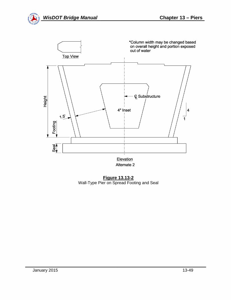
WisDOT Bridge Manual Chapter 13 – Piers
January 2015 13-49
Figure 13.13-2 Wall-Type Pier on Spread Footing and Seal

WisDOT Bridge Manual Chapter 13 – Piers
January 2015 13-50
13.14 Appendix B – Pile Encased Pier Construction
The following procedures shall be employed in the construction of pile encased piers which are constructed without cofferdams. The contractor shall have the option of driving piling prior to excavation. Excavation shall proceed in the following manner.
The area occupied by the pier and formwork shall be over-excavated a minimum of 2’ below the bottom of pier elevation. This area shall be partially filled with clean stone to a point approximately 6” below concrete grade. The preassembled form shall then be lowered into position. The form shall then be properly positioned, plumbed and secured to prevent movement during the pouring operation. Clean stone shall then be placed inside the form to ensure that concrete cannot leak out from under the form, as well as to attain the bottom of pier elevation.
Reinforcing steel may be incorporated in the form prior to setting, or it may be placed after the form has been set. A sufficient number of bar chairs shall be used to ensure that proper clearances are achieved.
Concrete shall then be placed through the use of an appropriate number of tremies for the width and height of the pier. The movement of tremies and recharging shall be limited as much as possible. Placement operations shall be in accordance with Subsection 502.3.5.3 of the Standard Specifications. When the concrete reaches an elevation above the water elevation, the surface shall be checked for any unsatisfactory materials which may have been forced upward as the concrete was being deposited. Any deleterious materials found shall be removed at that time from inside the form. Further concrete placement may then proceed using standard placement methods. Silt curtains or screens, as specified on the plans, shall be employed to limit downstream siltation. Displaced water shall be treated by filtration, settling basin or other approved means sufficient to reduce the cement content before being discharged into the stream.
After the formwork has been removed, the excavated area shall be backfilled to the original streambed elevation.

WisDOT Bridge Manual Chapter 13 – Piers
January 2015 13-51
13.15 Design Examples
E13-1 Hammerhead Pier Design Example
E13-2 Multi-Column Pier Design Example

WisDOT Bridge Manual
This page intentionally left blank.

Table of ContentsE13-1 Hammerhead Pier Design Example ..................................................................................................
E13-1.1 Obtain Design Criteria ..........................................................................................E13-1.1.1 Material Properties:...............................................................................E13-1.1.2 Reinforcing steel cover requirements: ..................................................
E13-1.2 Relevant superstructure data................................................................................E13-1.2.1 Girder Dead Load Reactions ................................................................E13-1.2.2 Live Load Reactions per Design Lane..................................................
E13-1.3 Select Preliminary Pier Dimensions......................................................................E13-1.4 Compute Dead Load Effects.................................................................................E13-1.5 Compute Live Load Effects...................................................................................E13-1.6 Compute Other Load Effects ................................................................................
E13-1.6.1 Braking Force .......................................................................................E13-1.6.2 Wind Load on Superstructure ...............................................................
E13-1.6.2.1 Vertical Wind Load................................................................E13-1.6.2.2 Wind Load on Vehicles .........................................................
E13-1.6.3 Wind Load on Substructure ..................................................................E13-1.6.4 Temperature Loading (Superimposed Deformations) ........................
E13-1.7 Analyze and Combine Force Effects ....................................................................E13-1.7.1 Pier Cap Force Effects..........................................................................E13-1.7.2 Pier Column Force Effects....................................................................E13-1.7.3 Pier Pile Force Effects ..........................................................................E13-1.7.4 Pier Footing Force Effects ....................................................................
E13-1.8 Design Pier Cap Strut and Tie Model (STM) ......................................................E13-1.8.1 Determine Geometry and Member Forces ...........................................E13-1.8.2 Check the Size of the Bearings ............................................................E13-1.8.3 Calculate the Tension Tie Reinforcement.............................................E13-1.8.4 Calculate the Stirrup Reinforcement.....................................................E13-1.8.5 Compression Strut Capacity Bottom Strut ............................................E13-1.8.6 Compression Strut Capacity Diagonal Strut .........................................E13-1.8.7 Check the Anchorage of the Tension Ties............................................E13-1.8.8 Provide Crack Control Reinforcement ..................................................E13-1.8.9 Summary of Cap Reinforcement ..........................................................
E13-1.9 Design Pier Column..............................................................................................E13-1.9.1 Design for Axial Load and Biaxial Bending (Strength V): ...................E13-1.9.2 Design for Shear (Strength III and Strength V) ...................................E13-1.9.3 Transfer of Force at Base of Column....................................................
E13-1.10 Design Pier Piles ................................................................................................E13-1.11 Design Pier Footing ............................................................................................
E13-1.11.1 Design for Moment .............................................................................E13-1.11.2 Punching Shear Check .......................................................................E13-1.11.3 One Way Shear Check .......................................................................
E13-1.12 Final Pier Schematic...........................................................................................
2233344467
1010111516171920242628313233373840414345474949505556586264687275
WisDOT Bridge Manual Chapter 13 – Piers

E13-1 Hammerhead Pier Design Example
This example shows design calculations conforming to the AASHTO LRFD Bridge DesignSpecifications (Seventh Edition) as supplemented by the WisDOT Bridge Manual The designmethods presented throughout the example are meant to be the most widely used in generalbridge engineering practice.
The first design step is to identify the appropriate design criteria. This includes, but is notlimited to, defining material properties, identifying relevant superstructure information, anddetermining the required pier geometry.
|
E13-1.1 Obtain Design Criteria
This pier is designed for the superstructure as detailed in example E24-1. This is a two-spansteel girder stream crossing structure. Expansion bearings are located at the abutments, andfixed bearings are used at the pier.
120'-0” 120'-0”
240'-0”
L Bearing Abutment
L Bearing Abutment
L Pier
EFE
CCC
Figure E13-1.1-1Bridge Elevation
2'-8”
3'-9" 3'-9"
10'-0”Shoulder
4 Spaces @ 9’-9” = 39’-0”
1'-5 3/8" (Typ.)
12'-0”Lane
12'-0”Lane
10'-0”Shoulder
46'-10 3/4" Out-to-Out
9"Type LF Parapet
1'-3"(Typ.)
Figure E13-1.1-2Bridge Cross Section
January 2015 13E1-2
WisDOT Bridge Manual Chapter 13 – Piers

E13-1.1.1 Material Properties:
wc 0.150 unit weight of concrete, kcf
f'c 3.5 concrete 28-day compressive strength, ksi
fy 60 reinforcement strength, ksi
E13-1.1.2 Reinforcing steel cover requirements:
All cover dimensions listed below are in accordance with LRFD [Table 5.12.3-1] and are shownin inches.
Covercp 2.5 Pier cap
Coverco 2.5 Pier column
Coverft 2.0 Footing top cover
Coverfb 6.0 Footing bottom cover, based on standard pile projection
E13-1.2 Relevant superstructure data
wdeck 46.50 Deck Width, ft
wroadway 44.0 Roadway Width, ft
ng 5 Number of Girders
S 9.75 Girder Spacing, ft
DOH 3.75 Deck Overhang, ft (Note that this overhang exceeds the limitsstated in Chapter 17.6.2. WisDOT practice is to limit theoverhang to 3'-7".)
Nspans 2
L 120.0 Span Length, ft
skew 0 Degrees
Hsuper 8.46 Superstructure Depth, ft
Hbrng 6.375 Bearing Height, in (Fixed, Type A)
Wbrng 18 Bearing Width, in
Lbrng 26 Bearing Length, in
μmax 0.10 Max. Coefficient of Friction of Abutment Expansion Bearings
μmin 0.06 Min. Coefficient of Friction of Abutment Expansion Bearings
January 2015 13E1-3
WisDOT Bridge Manual Chapter 13 – Piers

E13-1.2.1 Girder Dead Load Reactions
Unfactored Dead Load Reactions, kips
DLRint
"LoadType"
"Beam"
"Misc"
"Deck"
"Parapet"
"FWS"
"Abut"
7.00
1.23
46.89
6.57
7.46
"Pier"
34.02
4.73
178.91
24.06
27.32
DLRext
"LoadType"
"Beam"
"Misc"
"Deck"
"Parapet"
"FWS"
"Abut"
7.00
0.83
48.57
6.57
7.46
"Pier"
34.02
3.15
185.42
24.06
27.32
AbutRintDC 61.69 kips AbutRextDC 62.97 kips
AbutRintDW 7.46 kips AbutRextDW 7.46 kips
Pier Reactions:
RintDC 241.72 kips RextDC 246.65 kips
RintDW 27.32 kips RextDW 27.32 kips
E13-1.2.2 Live Load Reactions per Design Lane
Unfactored Live Load Reactions, kips
LLR
"LoadType"
"Vehicle"
"Lane"
"Abut"
64.72
32.76
"Pier"
114.17
89.41
These loads are per design lane and do not include dynamic load allowance. The pierreactions are controlled by the 90% (Truck Pair + Lane) loading condition. The reactionsshown include the 90% factor.
E13-1.3 Select Preliminary Pier Dimensions
Selecting the most optimal pier type depends on site conditions, cost considerations,superstructure geometry, and aesthetics. For this design example, a single column(hammerhead) pier was chosen.
Since the Specifications do not have standards regarding maximum or minimum dimensions fora pier cap, column, or footing, the designer should base the preliminary pier dimensions onWisDOT specific standards, previous designs, and past experience. The pier cap, however,must be wide enough to accommodate the bearing.
January 2015 13E1-4
WisDOT Bridge Manual Chapter 13 – Piers

Figures E13-1.3-1 and E13-1.3-2 show the preliminary dimensions selected for this pier designexample.
5'-0
"6'
-0"
15'-0
" 15'-6"
46'-6"
3'-6
"
23'-0"
15'-6"
2'-0
"
Figure E13-1.3-1Preliminary Pier Dimensions - Front Elevation
January 2015 13E1-5
WisDOT Bridge Manual Chapter 13 – Piers

5'-0
"6
'-0"
4'-0"
12'-0"
4'-0"
Figure E13-1.3-2Preliminary Pier Dimensions - End Elevation
Pier Geometry Definitions (feet):
Lcap 46.5 Lcol 15.5 Lftg 23 Dsoil 2
Wcap 4 Wcol 4 Wftg 12 γsoil 0.120
Hcap 11 Hcol 15 Hftg 3.5
Hcap_end 5
Loh 15.5
E13-1.4 Compute Dead Load Effects
Once the preliminary pier dimensions are selected, the corresponding dead loads can becomputed in accordance with LRFD [3.5.1]. The pier dead loads must then be combined withthe superstructure dead loads.
Exterior girder dead load reactions (DC and DW): RextDC 246.65 kips
RextDW 27.32 kips
January 2015 13E1-6
WisDOT Bridge Manual Chapter 13 – Piers

Interior girder dead load reactions (DC and DW): RintDC 241.72 kips
RintDW 27.32 kips
Pier cap dead load:
DLCap wc Wcap 2Hcap_end Hcap
2
Loh Hcap Lcol
0.150 4 25 11
2 15.5 11 15.5
DLCap 251.1 kips
Pier column dead load:
DLcol wc Wcol Hcol Lcol
0.150 4 15 15.5 DLcol 139.5 kips
Pier footing dead load:
DLftg wc Wftg Hftg Lftg
0.150 12 3.5 23 DLftg 144.9 kips
In addition to the above dead loads, the weight of the soil on top of the footing must becomputed. The two-foot height of soil above the footing was previously defined. Assuming aunit weight of soil at 0.120 kcf in accordance with LRFD [Table 3.5.1-1] :
EVftg γsoil Dsoil Wftg Lftg Wcol Lcol
0.120 2 12 23 4 15.5( ) EVftg 51.36 kips
E13-1.5 Compute Live Load Effects
For the pier in this design example, the maximum live load effects in the pier cap, column andfooting are based on either one, two or three lanes loaded (whichever results in the worst forceeffect). Figure E13-1.5-1 illustrates the lane positions when three lanes are loaded.
The positioning shown in Figure E13-1.5-1 is determined in accordance with LRFD [3.6.1].The first step is to calculate the number of design lanes, which is the integer part of the ratio ofthe clear roadway width divided by 12 feet per lane. Then the lane loading, which occupiesten feet of the lane, and the HL-93 truck loading, which has a six-foot wheel spacing and atwo-foot clearance to the edge of the lane, are positioned within each lane to maximize theforce effects in each of the respective pier components.
January 2015 13E1-7
WisDOT Bridge Manual Chapter 13 – Piers

12'-0” Lane - C
44'-0"
2'-0"
6'-0"
2'-0"
12'-0” Lane - B
2'-0"
6'-0"
2'-0"
12'-0” Lane - A
2'-0"
6'-0"
2'-0"
9'-9"9'-9"9'-9"9'-9" 2'-6"
L PierC
1 2 3 4 5
w
PP
ww
PP PP
2'-0"
Figure E13-1.5-1Pier Live Loading
N = maximum number of design lanes that the bridge can accommodatewroadway = roadway width between curbs, ignoring any median strip
W = design lane width
W 12 feet
wroadway 44 feet
Nwroadway
W N 3.67
N 3 design lanes
The unfactored girder reactions for lane load and truck load are obtained from thesuperstructure analysis and are as shown in E13-1.1.3.2. These reactions do not includedynamic load allowance and are given on a per lane basis (i.e., distribution factor = 1.0). Also,the reactions include the ten percent reduction permitted by the Specifications for interior pierreactions that result from longitudinally loading the superstructure with a truck pair inconjunction with lane loading LRFD [3.6.1.3.1].
January 2015 13E1-8
WisDOT Bridge Manual Chapter 13 – Piers

Rtruck 114.17 kips
Rlane 89.41 kips
IM 0.33 Dynamic load allowance, IM from LRFD [Table 3.6.2.1-1]
The values of the unfactored concentrated loads which represent the girder truck pair loadreaction per wheel line in Figure E13-1.5-1 are:
PwheelRtruck
21 IM( ) Pwheel 75.92 kips
The value of the unfactored uniformly distributed load which represents the girder lane loadreaction in Figure E13-1.5-1 is computed next. This load is transversely distributed over tenfeet and is not subject to dynamic load allowance, LRFD [3.6.2.1].
WlaneRlane
10
Wlane 8.94kips
ft
The next step is to compute the reactions due to the above loads at each of the five bearinglocations. This is generally carried out by assuming the deck is pinned (i.e., discontinuous) atthe interior girder locations but continuous over the exterior girders. Solving for the reactions isthen elementary. The computations for the reactions with only Lane C loaded are illustratedbelow as an example. The subscripts indicate the bearing location and the lane loaded toobtain the respective reaction:
R5_cPwheel 4.25 10.25( ) Wlane 10 7.25
9.75 R5_c 179.4 kips
R4_c Pwheel 2 Wlane 10 R5_c R4_c 61.86 kips
The reactions at bearings 1, 2 and 3 with only Lane C loaded are zero. Calculations similar tothose above yield the following live load reactions with the remaining lanes loaded. Allreactions shown are in kips.
Lane A Loaded Lane B Loaded Lane C Loaded
R5_a 0.0 R5_b 0.0 R5_c 179.4
R4_a 0.0 R4_b 123.66 R4_c 61.86
R3_a 72.31 R3_b 117.56 R3_c 0.0
R2_a 164.67 R2_b 0.0 R2_c 0.0
R1_a 4.27 R1_b 0.0 R1_c 0.0
January 2015 13E1-9
WisDOT Bridge Manual Chapter 13 – Piers

E13-1.6 Compute Other Load Effects
Other load effects that will be considered for this pier design include braking force, wind loads,and temperature loads.
For simplicity, buoyancy, stream pressure, ice loads and earthquake loads are not included inthis design example.
E13-1.6.1 Braking Force
Since expansion bearings exist at the abutments, the entire longitudinal braking force isresisted by the pier.
In accordance with LRFD [3.6.4], the braking force per lane is the greater of:
25 percent of the axle weights of the design truck or tandem
5 percent of the axle weights of the design truck plus lane load
5 percent of the axle weights of the design tandem plus lane load
The total braking force is computed based on the number of design lanes in the samedirection. It is assumed in this example that this bridge is likely to become one-directional in thefuture. Therefore, any and all design lanes may be used to compute the governing brakingforce. Also, braking forces are not increased for dynamic load allowance in accordance withLRFD [3.6.2.1]. The calculation of the braking force for a single traffic lane follows:
25 percent of the design truck:
BRKtrk 0.25 32 32 8( ) BRKtrk 18 kips
25 percent of the design tandem:
BRKtan 0.25 25 25( ) BRKtan 12.5 kips
5 percent of the axle weights of the design truck plus lane load:
BRKtrk_lan 0.05 32 32 8( ) 0.64 2 L( )[ ] BRKtrk_lan 11.28 kips
5 percent of the axle weights of the design tandem plus lane load:
BRKtan_lan 0.05 25 25( ) 0.64 2 L( )[ ] BRKtan_lan 10.18 kips
Use:
BRK max BRKtrk BRKtan BRKtrk_lan BRKtan_lan BRK 18 kips per lane
January 2015 13E1-10
WisDOT Bridge Manual Chapter 13 – Piers

LRFD [3.6.4] states that the braking force is applied along the longitudinal axis of the bridge ata distance of six feet above the roadway surface. However, since the skew angle is zero for thisdesign example and the bearings are assumed incapable of transmitting longitudinal moment,the braking force will be applied at the top of bearing elevation. For bridges with skews, thecomponent of the braking force in the transverse direction would be applied six feet above theroadway surface.
This force may be applied in either horizontal direction (back or ahead station) to cause themaximum force effects. Additionally, the total braking force is typically assumed equallydistributed among the bearings:
BRKbrgBRK
5 BRKbrg 3.6 kips per
bearing perlane
The moment arm about the base of the column is:
HBRK Hcol HcapHbrng
12 HBRK 26.53 feet
E13-1.6.2 Wind Load on Superstructure
Prior to calculating the wind load on the superstructure, the structure must be checked for aeroelastic instability, LRFD [3.8.3]. If the span length to width or depth ratio is greater than 30, thestructure is considered wind-sensitive and design wind loads should be based on wind tunnelstudies.
L 120 feet
Width wdeck Width 46.5 feet
Depth Hsuper Hpar Depth 5.79 feet
L
Width2.58 OK
L
Depth20.72 OK
Since the span length to width and depth ratios are both less than 30, the structure does notneed to be investigated for aero elastic instability.
To compute the wind load on the superstructure, the area of the superstructure exposed to thewind must be defined. For this example, the exposed area is the total superstructure depthmultiplied by length tributary to the pier. Due to expansion bearings at the abutment, thetransverse length tributary to the pier is not the same as the longitudinal length.
The superstructure depth includes the total depth from the top of the barrier to the bottom ofthe girder. Included in this depth is any haunch and/or depth due to the deck cross-slope.Once the total depth is known, the wind area can be calculated and the wind pressure applied.
January 2015 13E1-11
WisDOT Bridge Manual Chapter 13 – Piers

The total depth was previously computed in Section E13-1.1 and is as follows: Hsuper 8.46 feet
For this two-span bridge example, the tributary length for wind load on the pier in thetransverse direction is one-half of each span:
LwindTL L
2 LwindT 120 feet
In the longitudinal direction, the tributary length is the entire bridge length due to the expansionbearings at the abutments:
LwindL L 2 LwindL 240 feet
The transverse wind area is:
AwsuperT Hsuper LwindT AwsuperT 1015 ft2
The longitudinal wind area is:
AwsuperL Hsuper LwindL AwsuperL 2031 ft2
In accordance with Section 13.4.4, the design wind velocity, VB is equal to 100 mph and the
design wind pressure does not need to be adjusted. The design wind pressures, per Section13.4.4.1, are as follows and shall be applied simultaneously:
Psuptrans 0.050 ksf
Psuplongit 0.019 ksf
Also, the minimum transverse normal wind loading on girders must be greater than or equal to0.30 klf:
Windtotal Psuptrans Hsuper Windtotal 0.42 klf
which is greater than 0.30 klf
January 2015 13E1-12
WisDOT Bridge Manual Chapter 13 – Piers

Plan View
Elevation View
Girder Line
8.4
6'
Sup
ers
truc
ture
D
epth
90.0°
Pier Cap
Transverse Wind Loads
LongitudinalWind Loads
Figure E13-1.6-1Application of Wind Load
The superstructure wind loads acting on the pier (girders) are:
WSsuptrns AwsuperT Psuptrans WSsuptrns 50.77 kips
WSsuplng AwsuperL Psuplongit WSsuplng 38.59 kips
The total longitudinal wind load shown above is assumed to be divided equally among thebearings. In addition, the load at each bearing is assumed to be applied at the top of thebearing. These assumptions are consistent with those used in determining the bearing forces due to the longitudinal braking force.
The transverse wind loads shown above are also assumed to be equally divided among thebearings but are applied at the mid-height of the superstructure.
For calculating the resulting moment effect on the column, the moment arm about the base ofthe column is:
January 2015 13E1-13
WisDOT Bridge Manual Chapter 13 – Piers

HWSlong Hcol HcapHbrng
12 HWSlong 26.53 feet
HWStrns Hcol HcapHbrng
12
Hsuper
2 HWStrns 30.76 feet
However, the transverse load also applies a moment to the pier cap. This moment, which actsabout the centerline of the pier cap, induces vertical loads at the bearings as illustrated inFigure E13-1.6-2. The computations for these vertical forces are presented below.
4 Spaces @ 9’-9” = 39’-0”
46'-10½"
Figure E13-1.6-2Transverse Wind Loads at Pier Bearings from Wind on Superstructure
Mtrns WSsuptrnsHsuper
2
Mtrns 214.8 kip-ft
Moment of Inertia for the Girder Group:
I ΣA y2=
A = 1 I1 = I5 I2 = I4 I3 = 0
Igirders 2 S S( )2 2 S
2
2 9.75 9.75( )2 2 9.75
2 Igirders 950.63 ft2
ReactionMoment y
I=
January 2015 13E1-14
WisDOT Bridge Manual Chapter 13 – Piers

RWS1_5trnsMtrns S S( )
Igirders RWS1_5trns 4.41 kips
The loads at bearings 1 and 5 are equal but opposite in direction. Similarly for bearings 2 and4:
RWS2_4trnsMtrns S
Igirders RWS2_4trns 2.2 kips
Finally, by inspection: RWS3trns 0 kips
E13-1.6.2.1 Vertical Wind Load
The vertical (upward) wind load is calculated by multiplying a 0.020 ksf vertical wind pressureby the out-to-out bridge deck width. It is applied at the windward quarter-point of the deck onlyfor limit states that do not include wind on live load.
From previous definitions:
wdeck 46.5 ft LwindT 120 ft
The total vertical wind load is then:
WSvert 0.02 wdeck LwindT WSvert 111.6 kips
4 Spaces @ 9’-9” = 39’-0”
46'-6"
WSvertwDeck/4
Figure E13-1.6-3Vertical Wind Loads at Pier Bearings from Wind on Superstructure
This load causes a moment about the pier centerline. The value of this moment is:
January 2015 13E1-15
WisDOT Bridge Manual Chapter 13 – Piers

MWS_vert WSvertWidth
4 MWS_vert 1297.35 kip-ft
The loads at the bearings are computed as follows:
RWSvert1WSvert
5
MWS_vert 2 S( )
Igirders RWSvert1 4.29 kips
RWSvert2WSvert
5
MWS_vert S
Igirders RWSvert2 9.01 kips
RWSvert3WSvert
5 RWSvert3 22.32 kips
RWSvert4WSvert
5
MWS_vert S
Igirders RWSvert4 35.63 kips
RWSvert5WSvert
5
MWS_vert 2 S
Igirders RWSvert5 48.93 kips
Where a negative value indicates a vertical upward load.
E13-1.6.2.2 Wind Load on Vehicles
The representation of wind pressure acting on vehicular traffic is given by the Specifications asa uniformly distributed load. This load is applied both transversely and longitudinally. For thetransverse and longitudinal loadings, the total force in each respective direction is calculatedby multiplying the appropriate component by the length of structure tributary to the pier. Similarto the superstructure wind loading, the longitudinal length tributary to the pier differs from thetransverse length. In accordance with Section 13.4.4.3 the transverse and longitudinal loadsshown below shall be applied simultaneously. Also see 13.5.
LwindT 120 feet LwindL 240 feet
PLLtrans 0.100 klf
PLLlongit 0.040 klf
WLtrans LwindT PLLtrans WLtrans 12 kips
WLlong LwindL PLLlongit WLlong 9.6 kips
The wind on vehicular live loads shown above are applied to the bearings in the same manneras the wind load from the superstructure. That is, the total transverse and longitudinal load isequally distributed to each bearing and applied at the the top of the bearing. In addition, thetransverse load acting six feet above the roadway applies a moment to the pier cap. Thismoment induces vertical reactions at the bearings. The values of these vertical reactions aregiven below. The computations for these reactions are not shown but are carried out as shown
January 2015 13E1-16
WisDOT Bridge Manual Chapter 13 – Piers

in the subsection "Wind Load from Superstructure." The only difference is that the momentarm used for calculating the moment is equal to (Hsuper - Hpar + 6.0 feet).
RWL1_5trns 2.9 kips
RWL2_4trns 1.45 kips
RWL3trns 0 kips
For calculating the resulting moment effect on the column, the moment arm about the base ofthe column is:
HWLlong Hcol HcapHbrng
12 HWLlong 26.53 feet
HWLtrns Hcol HcapHbrng
12 Hsuper Hpar 6 HWLtrns 38.32 feet
E13-1.6.3 Wind Load on Substructure
The Specifications state that the wind loads acting directly on substructure units shall becalculated from a base wind pressure of 0.040 ksf. In accordance with Section 13.4.4.2, theseloads are applied simultaneously in the transverse and longitudinal directions of the pier.These loads act simultaneously with the superstructure wind loads.
January 2015 13E1-17
WisDOT Bridge Manual Chapter 13 – Piers

Pier Cap
Plan View
Transverse Wind Loads
Lo
ng
itud
ina
l Win
d L
oa
ds
Figure E13-1.6-4Wind Pressure on Pier
What follows is an example of the calculation of the wind loads acting directly on the pier. Forsimplicity, the tapers of the pier cap overhangs will be considered solid. The column heightexposed to wind is the distance from the ground line (which is two feet above the footing) to thebottom of the pier cap.
Component areas of the pier cap:
AcapLong Lcap Hcap AcapLong 511.5 ft2
AcapTrans Wcap Hcap AcapTrans 44 ft2
Component areas of the pier column:
AcolLong Lcol Hcol Dsoil AcolLong 201.5 ft2
AcolTrans Wcol Hcol Dsoil AcolTrans 52 ft2
The transverse and longitudinal force components are:
January 2015 13E1-18
WisDOT Bridge Manual Chapter 13 – Piers

Psub 0.040 ksf
WSsubL Psub AcapLong AcolLong WSsubL 28.52 kips
WSsubT Psub AcapTrans AcolTrans WSsubT 3.84 kips
The point of application of these loads will be the centroid of the loaded area of each face,respectively.
HWSsubL
AcapLong HcolHcap
2
AcolLongHcol 2
22
AcapLong AcolLong
HWSsubL 17.11 feet
HWSsubT
AcapTrans HcolHcap
2
AcolTransHcol 2
22
AcapTrans AcolTrans
HWSsubT 14 feet
E13-1.6.4 Temperature Loading (Superimposed Deformations)
In this particular structure, with a single pier centered between two abutments that haveidentical bearing types, the temperature force is based on assuming a minimum coefficient ofexpansion at one abutment and the maximum at the other using only dead load reactions. Thisforce acts in the longitudinal direction of the bridge (either back or ahead station) and isequally divided among the bearings. Also, the forces at each bearing from this load will beapplied at the top of the bearing.
The abutment girder Dead Load reactions from E13-1.1.3.1 are as follows:
AbutRintDC 61.69 AbutRextDC 62.97
AbutRintDW 7.46 AbutRextDW 7.46
μmin 0.06
μmax 0.1
Δμ μmax μmin Δμ 0.04
FTU Δμ 3 AbutRintDC AbutRintDW 2 AbutRextDC AbutRextDW
FTU 13.93 kips
The resulting temperature force acting on each bearing is:
January 2015 13E1-19
WisDOT Bridge Manual Chapter 13 – Piers

TUBRGFTU
5 TUBRG 2.79 kips
The moment arm about the base of the column is:
HTU Hcol HcapHbrng
12 HTU 26.53 feet
E13-1.7 Analyze and Combine Force Effects
The first step within this design step will be to summarize the loads acting on the pier at thebearing locations. This is done in Tables E13-1.7-1 through E13-1.7-8 shown below. TablesE13-1.7-1 through E13-1.7-5 summarize the vertical loads, Tables E13-1.7-6 throughE13-1.7-7 summarize the horizontal longitudinal loads, and Table E13-1.7-8 summarizes thehorizontal transverse loads. These loads along with the pier self-weight loads, which are shownafter the tables, need to be factored and combined to obtain total design forces to be resistedin the pier cap, column and footing.
It will be noted here that loads applied due to braking and temperature can act either ahead orback station. Also, wind loads can act on either side of the structure and with positive ornegative skew angles. This must be kept in mind when considering the signs of the forces inthe tables below. The tables assume a particular direction for illustration only.
BearingVariable
NameReaction
(Kips)Variable
NameReaction
(Kips)
1 RextDC 246.65 RextDW 27.32
2 RintDC 241.72 RextDW 27.32
3 RintDC 241.72 RextDW 27.32
4 RintDC 241.72 RextDW 27.32
5 RextDC 246.65 RextDW 27.32
Superstructure Dead Load
Wearing Surface Dead Load
Table E13-1.7-1Unfactored Vertical Bearing Reactions from Superstructure Dead Load
January 2015 13E1-20
WisDOT Bridge Manual Chapter 13 – Piers

BearingVariable Name
Reaction (Kips)
Variable Name
Reaction (Kips)
Variable Name
Reaction (Kips)
1 R1_a 4.27 R1_b 0.00 R1_c 0.00
2 R2_a 164.67 R2_b 0.00 R2_c 0.00
3 R3_a 72.31 R3_b 117.56 R3_c 0.00
4 R4_a 0.00 R4_b 123.66 R4_c 61.86
5 R5_a 0.00 R5_b 0.00 R5_c 179.40
Lane A Lane B Lane C
Vehicular Live Load **
**Note: Live load reactions include impact on truck loading.
Table E13-1.7-2Unfactored Vertical Bearing Reactions from Live Load
Bearing No.12345
-2.20-4.41
Reactions from Transverse Wind Load on Superstructure (kips)
4.412.200.00
Table E13-1.7-3Unfactored Vertical Bearing Reactions from Wind on Superstructure
Bearing No.12345
0.00-1.45-2.90
Reactions from Transverse Wind Load on Vehicular Live Load (kips)
2.901.45
Table E13-1.7-4 Unfactored Vertical Bearing Reactions from Wind on Live Load
January 2015 13E1-21
WisDOT Bridge Manual Chapter 13 – Piers

Variable Name
Reaction (Kips)
Variable Name
Reaction (Kips)
BRKbrg 3.60 TU1 2.79
Braking Load **Temperature
Loading
Each Bearing
Bearing No.
Variable Name
Reaction (Kips)
1 RWSvert1 4.29
2 RWSvert2 -9.01
3 RWSvert3 -22.32
4 RWSvert4 -35.63
5 RWSvert5 -48.93
Vertical Wind Load on Superstructure
Table E13-1.7-5Unfactored Vertical Bearing Reactions from Vertical Wind on Superstructure
**Note: Values shown are for a single lane loaded
Table E13-1.7-6Unfactored Horizontal Longitudinal Bearing Reactions from Braking and Temperature
Load TypeWind Loads from Superstructure
Wind on Live LoadWind on Pier 28.52
Unfactored Horizontal Longitudinal Forces (kips)
38.599.60
Table E13-1.7-7Unfactored Horizontal Longitudinal Forces
January 2015 13E1-22
WisDOT Bridge Manual Chapter 13 – Piers

Load TypeWind Loads from Superstructure
Wind on Live LoadWind on Pier 3.84
Unfactored Horizontal Transverse Forces (kips)
50.7712.00
Table E13-1.7-8Unfactored Horizontal Transverse Forces
In addition to all the loads tabulated above, the pier self-weight must be considered whendetermining the final design forces. Additionally for the footing and pile designs, the weight ofthe earth on top of the footing must be considered. These loads were previously calculatedand are shown below:
DLCap 251.1 kips DLftg 144.9 kips
DLcol 139.5 kips EVftg 51.36 kips
In the AASHTO LRFD design philosophy, the applied loads are factored by statisticallycalibrated load factors. In addition to these factors, one must be aware of two additional sets offactors which may further modify the applied loads.
The first set of additional factors applies to all force effects and are represented by the Greekletter h (eta) in the Specifications, LRFD [1.3.2.1]. These factors are related to the ductility,redundancy, and operational importance of the structure. A single, combined eta is required forevery structure. In accordance with WisDOT policy, all eta factors are taken equal to one.
The other set of factors mentioned in the first paragraph above applies only to the live loadforce effects and are dependent upon the number of loaded lanes. These factors are termedmultiple presence factors by the Specifications, LRFD [T3.6.1.1.2-1]. These factors for thisbridge are shown as follows:
Multiple presence factor, m (1 lane) m1 1.20
Multiple presence factor, m (2 lanes) m2 1.00
Multiple presence factor, m (3 lanes) m3 0.85
Table E13-1.7-9 contains the applicable limit states and corresponding load factors that will beused for this pier design. Limit states not shown either do not control the design or are notapplicable. The load factors shown in Table E13-1.7-9 are the standard load factors assignedby the Specifications and are exclusive of multiple presence and eta factors.
It is important to note here that the maximum load factors shown in Table E13-1.7-9 for uniform
January 2015 13E1-23
WisDOT Bridge Manual Chapter 13 – Piers

temperature loading (TU) apply only for deformations, and the minimum load factors apply forall other effects. Since the force effects from the uniform temperature loading are considered inthis pier design, the minimum load factors will be used.
Load max min max min max min max min
DC 1.25 0.90 1.25 0.90 1.25 0.90 1.00 1.00DW 1.50 0.65 1.50 0.65 1.50 0.65 1.00 1.00LL 1.75 1.75 --- --- 1.35 1.35 1.00 1.00BR 1.75 1.75 --- --- 1.35 1.35 1.00 1.00TU 1.20 0.50 1.20 0.50 1.20 0.50 1.20 1.00WS --- --- 1.40 1.40 0.40 0.40 0.30 0.30WL --- --- --- --- 1.00 1.00 1.00 1.00EV 1.35 1.00 1.35 1.00 1.35 1.00 1.00 1.00
Strength V Service I
Load Factors
Strength I Strength III
Table E13-1.7-9Load Factors and Applicable Pier Limit States
The loads discussed and tabulated previously can now be factored by the appropriate loadfactors and combined to determine the governing limit states in the pier cap, column, footingand piles. Design calculations will be carried out for the governing limit states only.
E13-1.7.1 Pier Cap Force Effects
The pier cap will be designed using a strut and tie model. See E13-1.8 for additionalinformation. For this type of model, the member's self weight is included in the bearingreactions. The calculation of the Strength 1 Factored girder reactions follows.
For the dead load of the cap, the tributary weight of the cap will be added to each girderreaction.
CapDC_1 8.6255 8.34
2 Wcap wc CapDC_1 34.52 kips
CapDC_2 6.8758.34 11
2 2.875 11
Wcap wc CapDC_2 58.86 kips
CapDC_3 9.75 11 Wcap wc CapDC_3 64.35 kips
CapDC_4 CapDC_2 CapDC_4 58.86 kips
CapDC_5 CapDC_1 CapDC_5 34.52 kips
January 2015 13E1-24
WisDOT Bridge Manual Chapter 13 – Piers

BearingVariable Name
Reaction (Kips)
Variable Name
Reaction (Kips)
Variable Name
Reaction (Kips)
1 Ru1_1 392.44 Ru1_2 392.44 Ru1_3 398.79
2 Ru2_1 416.71 Ru2_2 416.71 Ru2_3 661.66
3 Ru3_1 423.57 Ru3_b 629.30 Ru3_3 706.01
4 Ru4_1 546.62 Ru4_2 741.38 Ru4_3 692.68
5 Ru5_1 769.17 Ru5_b 706.38 Ru5_3 659.29
** Includes dead load of pier cap
1 Lane, m=1.2 2 Lanes, m=1.0 3 Lanes, m=0.85
Total Factored Girder Reactions**
BearingVariable Name
Reaction (Kips)
Variable Name
Reaction (Kips)
Variable Name
Reaction (Kips)
1 R1_1 0.00 R1_2 0.00 R1_3 3.63
2 R2_1 0.00 R2_2 0.00 R2_3 139.97
3 R3_1 0.00 R3_b 117.56 R3_3 161.40
4 R4_1 74.23 R4_2 185.52 R4_3 157.70
5 R5_1 215.27 R5_b 179.40 R5_3 152.49
1 Lane, m=1.2 2 Lanes, m=1.0 3 Lanes, m=0.85
Unfactored Vehicular Live Load
Look at the combined live load girder reactions with 1 (Lane C), 2 (Lanes C and B) and 3 lanes(Lanes C, B and A) loaded. The multiple presence factor from E13-1.7 shall be applied. Thedesign lane locations were located to maximize the forces over the right side of the cap.
Table E13-1.7-10Unfactored Vehicular Live Load Reactions
Calculate the Strength 1 Combined Girder Reactions for 1, 2 and 3 lanes loaded. An examplecalculation is shown for the girder 5 reaction with one lane loaded. Similar calculations areperformed for the remaining girders and number of lanes loaded.
Ru5_1 γDCmax RextDC CapDC_5 γDWmax RextDW γLL R5_1
Ru5_1 769.17 kips
Table E13-1.7-11Factored Girder Reactions for STM Cap Design
January 2015 13E1-25
WisDOT Bridge Manual Chapter 13 – Piers

E13-1.7.2 Pier Column Force Effects
The controlling limit states for the design of the pier column are Strength V (for biaxial bendingwith axial load). The critical design location is where the column meets the footing, or at thecolumn base. The governing force effects for Strength V are achieved by minimizing the axialeffects while maximizing the transverse and longitudinal moments. This is accomplished byexcluding the future wearing surface, applying minimum load factors on the structure deadload, and loading only Lane B and Lane C with live load.
For Strength V, the factored vertical forces and corresponding moments at the critical sectionare shown below.
Strength V Axial Force:
RextDC 246.65 kips R3_2 117.56 kips
RintDC 241.72 kips R4_2 185.52 kipswcap
DLCap 251.1 kips R5_2 179.4 kips
DLcol 139.5 kips
WSvert 111.6 kips (uplift)
AxcolStrV γDCminStrV 2 RextDC 3 RintDC DLCap DLcol γLLStrV R3_2 R4_2 R5_2
γWSStrV WSvert
AxcolStrV 2054.87 kips
Strength V Transverse moment:
ArmV3col 0 ArmV3col 0 feet
ArmV4col S ArmV4col 9.75 feet
ArmV5col 2 S ArmV5col 19.5 feet
WSsuptrns 50.77 kips HWStrns 30.76 feet
WLtrans 12 kips HWLtrns 38.32 feet
WSsubT 3.84 kips HWSsubT 14 feet
MWS_vert 1297.35 kip-ft
January 2015 13E1-26
WisDOT Bridge Manual Chapter 13 – Piers

MuTcolStrV γLLStrV R3_2 ArmV3col R4_2 ArmV4col R5_2 ArmV5col γWLStrV WLtrans HWLtrns
γWSStrV MWS_vert WSsuptrns HWStrns WSsubT HWSsubT
MuTcolStrV 8789.59 kip-ft
Strength V Longitudinal moment:
BRKbrg 3.6 kips/bearing per lane HBRK 26.53 feet
TUBRG 2.79 kips/ bearing HTU 26.53 feet
WSsuplng 38.59 kips HWSlong 26.53 feet
WLlong 9.6 kips HWLlong 26.53 feet
WSsubL 28.52 kips HWSsubL 17.11 feet
m2 1.00 multi presence factor for two lanes loaded
MuLcolStrV γBRStrV 5 BRKbrg HBRK 2 m2 γTUminStrV 5TUBRG HTU
γWLStrV WLlong HWLlong
γWSStrV WSsuplng HWSlong WSsubL HWSsubL
MuLcolStrV 2333.6 kip-ft
For Strength III, the factored transverse shear in the column is:
WSsubT 3.84 kips WSsuptrns 50.77 kips
VuTcol γWSStrIII WSsuptrns WSsubT VuTcol 76.45 kips
For Strength V, the factored longitudinal shear in the column is (reference Table E13-1.7-7):
WLlong 9.6 WSsubL 28.52 WSsuplng 38.59 kips
VuLcol γWSStrV WSsuplng WSsubL γWLStrV WLlongγTUmin TUBRG 5 γBRStrV 5 BRKbrg 3 m3
VuLcol 105.37 kips
January 2015 13E1-27
WisDOT Bridge Manual Chapter 13 – Piers

E13-1.7.3 Pier Pile Force Effects
The foundation system for the pier is a reinforced concrete footing on steel H-piles. The forceeffects in the piles cannot be determined without a pile layout. The pile layout depends uponthe pile capacity and affects the footing design. The pile layout used for this pier foundation isshown in Figure E13-1.10-1.
Based on the pile layout shown in Figure E13-1.10-1, the controlling limit states for the piledesign are Strength I (for maximum pile load), Strength III (for minimum pile load), and StrengthV (for maximum horizontal loading of the pile group).
Structure Dead Load Effects
Girder DC Reactions: Girder DW Reactions:
RextDC 246.65 kips RextDW 27.32 kips
RintDC 241.72 kips RintDW 27.32 kips
DCSuper 2 RextDC 3 RintDC DCSuper 1218.46 kips
DLCap 251.1 kips
DLcol 139.5 kips
DLftg 144.9 kips
DCpile DCSuper DLCap DLcol DLftg DCpile 1753.96 kips
DWpile 2 RextDW 3 RintDW DWpile 136.6 kips
Vertical Earth Load Effects
EVpile EVftg EVpile 51.36 kips
Live Load Effects (without Dynamic Load Allowance)
Live Load Girder Reactions for 2 lanes, Lanes B and C, loaded:
R1_2p 0 kips
R2_2p 0 kips
R3_2p 99.21 kips
R4_2p 156.54 kips
R5_2p 151.38 kips RT_2p 407.13 kips
January 2015 13E1-28
WisDOT Bridge Manual Chapter 13 – Piers

From Section E13-1.7, the Transverse moment arm for girders 3, 4 and 5 are:
ArmV3col 0 feet
ArmV4col 9.75 feet
ArmV5col 19.5 feet
The resulting Transverse moment applied to the piles is:
MLL2T_p R3_2p ArmV3col R4_2p ArmV4col R5_2p ArmV5col
MLL2T_p 4478.2 kip-ft
The Longitudinal Strength 1 Moment includes the breaking and temperature forces.
MuL2colStr1 γBR 5 BRKbrg HBRK 2 m2 γTUmin 5TUBRG HTU
MuL2colStr1 1856.29 kip-ft
Strength 1 Load for Maximum Pile Reaction
The maximum pile load results from the Strength I load combination with two lanes loaded.
Pu2pile_Str1 γDCmax DCpile γDWmax DWpile γEVmax EVpile γLL RT_2p
Pu2pile_Str1 3179.17 kips
MuT2pile_Str1 γLL MLL2T_p MuT2pile_Str1 7836.85 kip-ft
MuL2pile_Str1 MuL2colStr1 MuL2pile_Str1 1856.29 kip-ft
Minimum Load on Piles Strength V
The calculation for the minimum axial load on piles is similar to the Strength V axial column loadcalculated previously. The weight of the footing and soil surcharge are included. The girderreactions used for pile design do not include impact. The DW loads are not included.
Pupile_StrV γDCminStrV 2 RextDC 3 RintDC DLCap DLcol DLftg γEVminStrV EVpile
γLLStrV R3_2p R4_2p R5_2p
γWSStrV WSvert
Pupile_StrV 2134.91 kips
January 2015 13E1-29
WisDOT Bridge Manual Chapter 13 – Piers

The calculation for the Strength V longitudinal moment is the same as the longitudinal momenton the column calculated previously. These loads include the breaking force, temperature,wind on live load and wind on the structure.
MuLpile_StrV γBRStrV 5 BRKbrg HBRK 2 m2 γTUminStrV 5TUBRG HTU
γWLStrV WLlong HWLlong
γWSStrV WSsuplng HWSlong WSsubL HWSsubL
MuLpile_StrV 2333.6 kip-ft
The calculation for the Strength V transverse moment is the similar as the transverse momenton the column calculated previously. These loads include the live load, wind on live load andwind on the structure. Impact is not included in these live load reactions.
MuTpile_StrV γLLStrV R3_2p ArmV3col R4_2p ArmV4col R5_2p ArmV5col γWLStrV WLtrans HWLtrns
γWSStrV MWS_vert WSsuptrns HWStrns WSsubT HWSsubT
MuTpile_StrV 7670.61 kip-ft
For Strength III, the factored transverse shear in the footing is equal to the transverse force atthe base of the column.
HuTpileStrIII VuTcol
γWSStrIII WSsuptrns WSsubT HuTpileStrIII 76.45 kips
For Strength V, the factored longitudinal shear in the column is equal to the longitudinal forceat the base of the column.
HuLpileStrV VuLcol HuLpileStrV 105.37 kips
The following is a summary of the controlling forces on the piles:
Strength Ikips
Pu2pile_Str1 3179.17
kip-ftMuT2pile_Str1 7836.85
kip-ftMuL2pile_Str1 1856.29
January 2015 13E1-30
WisDOT Bridge Manual Chapter 13 – Piers

Strength III
HuTpileStrIII 76.45 kips
Strength V
Pupile_StrV 2134.91 kips
MuTpile_StrV 7670.61 kip-ft
MuLpile_StrV 2333.6 kip-ft
kipsHuLpileStrV 105.37
E13-1.7.4 Pier Footing Force Effects
The controlling limit states for the design of the pier footing are Strength I (for flexure,punching shear at the column, and punching shear at the maximum loaded pile, andfor one-way shear). In accordance with Section 13.11, the footings do not require the crackcontrol by distribution check in LRFD [5.7.3.4]. As a result, the Service I Limit State is notrequired. There is not a single critical design location in the footing where all of the forceeffects just mentioned are checked. Rather, the force effects act at different locations in thefooting and must be checked at their respective locations. For example, the punching shearchecks are carried out using critical perimeters around the column and maximum loaded pile,while the flexure and one-way shear checks are carried out on a vertical face of the footingeither parallel or perpendicular to the bridge longitudinal axis. Also note that impact is notincluded for members that are below ground. The weight of the footing concrete and the soilabove the footing are not included in these loads as they counteract the pile reactions.
DCftg DCSuper DLCap DLcol DCftg 1609.06 kips
DWftg 2 RextDW 3 RintDW DWftg 136.6 kips
Unfactored Live Load reactions for one, two and three lanes loaded:
RT_1p 244.3 kips
RT_2p 407.13 kips
RT_3p 519.1 kips
The resulting Transverse moment applied to the piles is:
MLL1T R4_1p ArmV4col R5_1p ArmV5col MLL1T 4153.03 kip-ft
MLL2T R4_2p ArmV4col R5_2p ArmV5col MLL2T 4478.2 kip-ft
January 2015 13E1-31
WisDOT Bridge Manual Chapter 13 – Piers

MLL3T R2_3p R4_3p ArmV4col R1_3p R5_3p ArmV5col
MLL3T 2595.17 kip-ft
The maximum pile load results from the Strength I load combination with two lanes loaded.
Pu2ftgStr1 γDCmax DCftg γDWmax DWftg γLL RT_2p
Pu2ftgStr1 2928.7 kips
MuT2ftgStr1 γLL MLL2T MuT2ftgStr1 7836.85 kip-ft
MuL2ftgStr1 γBR 5 BRKbrg HBRK 2 m2 γTUmin 5TUBRG HTU
MuL2ftgStr1 1856.29 kip-ft
The Strength I limit state controls for the punching shear check at the column. In this case thefuture wearing surface is included, maximum factors are applied to all the dead loadcomponents, and all three lanes are loaded with live load. This results in the following bottomof column forces:
Pu3ftgStr1 γDCmax DCftg γDWmax DWftg γLL RT_3p
Pu3ftgStr1 3124.66 kips
MuT3ftgStr1 γLL MLL3T MuT3ftgStr1 4541.55 kip-ft
MuL3ftgStr1 γBR 5 BRKbrg HBRK 3 m3 γTUmin 5TUBRG HTU
MuL3ftgStr1 2315.94 kip-ft
E13-1.8 Design Pier Cap - Strut and Tie Model (STM)
Prior to carrying out the actual design of the pier cap, a brief discussion is in order regardingthe design philosophy that will be used for the design of the structural components of this pier.
When a structural member meets the definition of a deep component, the Specificationsrecommends, although does not mandate, that a strut-and-tie model be used to determineforce effects and required reinforcing. LRFD [C5.6.3.1] indicates that a strut-and-tie modelproperly accounts for nonlinear strain distribution, nonuniform shear distribution, and themechanical interaction of Vu, Tu and Mu. Use of strut-and-tie models for the design of
reinforced concrete members is new to the LRFD Specification. WisDOT policy is to designhammerhead pier caps using STM.
January 2015 13E1-32
WisDOT Bridge Manual Chapter 13 – Piers

E13-1.8.1 Determine Geometry and Member Forces
4.875'TYP.
9.75' 9.75' 9.75' 9.75'
10.1
7'
4.5
7'
0.8
0'
A B C
F
GH I
D E
J
K
G1 G2 G3 G4 G5
RH RI
9.75'
9.3
7
4.875'
10.
17'
4.875'
3.7
7'
9.75'9.
37'5.6
0'
10.45'
13.52' 11.28' 11.2
8'
0.80
'
4.875'
4.94'
4 ½
"5
½ "
Figure E13-1.8-1Strut and Tie Model Dimensions
In order to maintain a minimum 25o angle between struts and ties, the support nodes (H and I)are located midway between the girder reactions. For this example a compressive strut depthof 8 inches will be used, making the centroids of the bottom truss chords 4.5 inches from theconcrete surface. It is also assumed that two layers of rebar will be required along the toptension ties, and the centroid is located 5.5 inches below the top of the cap.
centroidbot 4.5 inches
centroidtop 5.5 inches
Strength I Loads:
BearingVariable Name
Reaction (Kips)
Variable Name
Reaction (Kips)
Variable Name
Reaction (Kips)
1 Ru1_1 392.44 Ru1_2 392.44 Ru1_3 398.79
2 Ru2_1 416.71 Ru2_2 416.71 Ru2_3 661.66
3 Ru3_1 423.57 Ru3_2 629.30 Ru3_3 706.01
4 Ru4_1 546.62 Ru4_2 741.38 Ru4_3 692.68
5 Ru5_1 769.17 Ru5_2 706.38 Ru5_3 659.29
** Includes dead load of pier cap
1 Lane, m=1.2 2 Lanes, m=1.0 3 Lanes, m=0.85
Total Factored Girder Reactions**
Table E13-1.8-1Total Factored Girder Reactions
January 2015 13E1-33
WisDOT Bridge Manual Chapter 13 – Piers

Calculate the forces in the members for the Strength I Load Case with 2 lanes loaded.
To find the column reaction at node I, sum moments about node H:
RI_2Ru3_2 4.875 Ru4_2 14.625 Ru5_2 24.375 Ru2_2 4.875 Ru1_2 14.625
9.75
RI_2 2395.66 kips
RH_2 Ru1_2 Ru2_2 Ru3_2 Ru4_2 Ru5_2 RI_2
RH_2 490.55 kips
The method of joints is used to calculate the member forces. Start at node K.
By inspection, the following are zero force members and can be ignored in the model:
FJK 0 FEK 0 FAF 0 FFG 0
Note: all forces shown are in kips. "C" indicates compression and "T" indicates tension.
At node E:
FEJ_vert Ru5_2 FEJ_vert 706.38
FEJ_horiz Ru5_2EJh
EJv FEJ_horiz 735.42
FEJ FEJ_vert2
FEJ_horiz2 FEJ 1019.71 C
FDE FEJ_horiz FDE 735.42 T
At node J:
FIJ_horiz FEJ_horiz FIJ_horiz 735.42
FIJ_vert FIJ_horiz0.802
4.875 FIJ_vert 120.99
FIJ FIJ_horiz2
FIJ_vert2 FIJ 745.31 C
FDJ FEJ_vert FIJ_vert FDJ 585.4 T
January 2015 13E1-34
WisDOT Bridge Manual Chapter 13 – Piers

At node D:
FDI_vert FDJ Ru4_2 FDI_vert 1326.77
FDI_horiz FDI_vert4.875
10.167 FDI_horiz 636.18
FDI FDI_vert2
FDI_horiz2 FDI 1471.41 C
FCD FDE FDI_horiz FCD 1371.6 T
At node I:
RI_2 2395.66
FCI_vert RI_2 FDI_vert FIJ_vert FCI_vert 947.9
FCI_horiz FCI_vert4.875
10.167 FCI_horiz 454.51
FCI FCI_vert2
FCI_horiz2 FCI 1051.23 C
FHI FDI_horiz FIJ_horiz FCI_horiz FHI 917.09 C
Similar calculations are performed to determine the member forces for the remainder of themodel and for the load cases with one and three lanes loaded. The results are summarized inthe following figures:
January 2015 13E1-35
WisDOT Bridge Manual Chapter 13 – Piers

A B C
F
GH I
D E
J
K
Ru1=392.44
408.6
0.0
0.0
325.
2
764.3 1371.6 735.4
353.
3
585.
4
0.0
0.0
-566.5
-822.8
-414.1
-1051.2
-917.1
-147
1.4
-101
9.7
Ru2=416.71
Ru3=629.30
Ru4=741.38
Ru5=706.38
RI=2395.7
RH=490.6
-745.3
Figure E13-1.8-2STM Member Forces (Two Lanes Loaded)
A B C
F
GH I
D E
J
K
Ru1=392.44
408.6
0.0
0.0
325.
2
764.3 1368.5 800.8
463.
9
637.
4
0.0
0.0
-566.5
-822.8
-414.1
-933.6
-964.9
-131
3.1
-111
0.4
Ru2=416.71
Ru3=423.57
Ru4=546.62
Ru5=769.17
RI=2157.6
RH=390.9
-811.6
Figure E13-1.8-3STM Member Forces (One Lane Loaded)
January 2015 13E1-36
WisDOT Bridge Manual Chapter 13 – Piers

A B C
F
GH I
D E
J
K
Ru1=398.79
415.2
0.0
0.0
330
.5
890.9 1280.5 686.4
59.1
546.
4
0.0
0.0
-575.7
-1100.3
-420.8
-842.0
-916.4
-137
4.1
-951
.7
Ru2=661.66
Ru3=706.01
Ru4=692.68
Ru5=659.29
RI=2111.2
RH=1007.2
-695.6
Figure E13-1.8-4STM Member Forces (Three Lanes Loaded)
E13-1.8.2 Check the Size of the Bearings
The node conditions are defined by the connecting types of struts and ties. The following tabledescribes the types of nodes and their corresponding limiting stresses.
Node Conditions DescriptionLimiting Concrete
Compressive Stress
CCC nodeStrut anchored by bearing plate and strut or continuous beam support.
0.85Φf'c
CCT nodeStruct anchored by one directional tension tie.
0.75Φf'c
CTT nodeStrut anchred by tension ties in more than one direction.
0.65Φf'c
Table E13-1.8-1Limiting Stresses for Pier Cap Nodes
Node C: CTTNode D: CTTNode E: CCTNode H: CCTNode I: CCC
ϕbrg 0.70
January 2015 13E1-37
WisDOT Bridge Manual Chapter 13 – Piers

At node D the critical concrete compressive strength equals:
0.65 ϕbrg f'c 1.59 ksi
At node E the critical concrete compressive strength equals:
0.75 ϕbrg f'c 1.84 ksi
Bearing area required:
Ru4_2 741.38
γDCmax CapDC_4 73.58
BrgD2Ru4_2 γDCmax CapDC_4
0.65 ϕbrg f'c BrgD2 419.34 in
2
Ru5_1 769.17
γDCmax CapDC_5 43.15
BrgE1Ru5_1 γDCmax CapDC_5
0.75 ϕbrg f'c BrgE1 395.11 in
2
The area provided by the bearing plate is:
Abrng Lbrng Wbrng Abrng 468 in2 OK
E13-1.8.3 Calculate the Tension Tie Reinforcement
For the top reinforcement over the column, the required area of tension tie reinforcement, Ast,
in Tie CD for two lanes loaded is calculated as follows:
PuCD_2 1371.6 kips
ϕ 0.9
AstCDPuCD_2
ϕ fy AstCD 25.4 in2
Therefore use one row of 9 No.11 bars and one row of 9 No. 10 bars spaced at 5 inches for thetop reinforcement.
AsNo11 1.5625 in2
AsNo10 1.2656 in2
January 2015 13E1-38
WisDOT Bridge Manual Chapter 13 – Piers

AsCD 9 AsNo11 9 AsNo10 AsCD 25.45 in2
check "OK"
48"
3.81" 3.81"
#5 Stirrups
9-#11 Bars
5.29
"
1.5"
cle
ar
9-#10 Bars
13.5"±
Figure E13-1.8-5Cap Reinforcement at Tension Tie CD
Note: See LRFD [5.10.3.1.3] for spacing requirements between layers of rebar.
For the top reinforcement past the first interior girder, the required area of tension tiereinforcement, Ast, in Tie DE for two lanes loaded is calculated as follows:
PuDE_1 800.79 kips
ϕ 0.9
AstDEPuDE_1
ϕ fy AstDE 14.83 in2
Therefore use one row of 9 No.11 bars spaced at 5 inches, and one row of 5 No.10 bars for thetop reinforcement.
AsDE 9 AsNo11 4 AsNo10 AsDE 19.12 in2
check "OK"
January 2015 13E1-39
WisDOT Bridge Manual Chapter 13 – Piers

48"
3.81" 3.81"
#5 Stirrups
1 Row of 9-#11 Bars,1 Row of 5-#10 Bars
1.5"
cle
ar
Figure E13-1.8-6Cap Reinforcement at Tension Tie DE
E13-1.8.4 Calculate the Stirrup Reinforcement
The vertical tension ties DJ must resist a factored tension of force as shown below. Thecontrolling force occurs with one lane loaded. This tension force will be resisted by stirrups within the specified length of the pier cap. Note that any tension ties located directly over thecolumn do not require stirrup design.
PuDJ_1 637.43 kips
nPu
ϕ Ast fy
Pu
Try number 5 bars, with four legs.
AsNo5 0.3068 in2
Ast 4 AsNo5 Ast 1.23 in2
nDJPuDJ_1
ϕ Ast fy nDJ 9.62
nDJ 10 bars
The length over which the stirrup shall be distributed is from the face of the column to half waybetween girders 4 and 5.
S 9.75 feet
LDJ 1.5 SLcol
2 LDJ 6.88 feet
Therefore the required spacing, s, within this region is:
January 2015 13E1-40
WisDOT Bridge Manual Chapter 13 – Piers

sstirrupLDJ 12
nDJ sstirrup 8.25 in
sstirrup 8 in
Crack control in disturbed regions:
Ast
bs0.003
bv Wcap 12 bv 48 in
sccAst
0.003 bv scc 8.52 in
scc 8 in
sstir min sstirrup scc sstir 8 in
AsDJ LDJ Ast12
8 AsDJ 12.66 in2
Therefore use No. 5 double-legged stirrups at 8 inch spacing in the pier cap.
E13-1.8.5 Compression Strut Capacity - Bottom Strut
After the tension tie reinforcement has been designed, the next step is to check the capacity ofthe compressive struts in the pier cap versus the limiting compressive stress. Strut IJ carriesthe highest bottom compressive force when one lane is loaded. Strut IJ is anchored by Node J,which also anchors ties DJ and strut EJ, From the geometry of the idealized internal truss, thesmallest angle is between Tie DJ and Strut IJ:
αs atanIJh
IJv
αs 80.66 deg
θ 90deg αs θ 9.34 deg
PuIJ_1 811.55 kips
Based on the design of the tension tie reinforcement, the tensile strain in Tie DJ is:
εsPu
Ast Es
Pu
January 2015 13E1-41
WisDOT Bridge Manual Chapter 13 – Piers

Es 29000 ksi
PuDJ_1 637.43 kips
LDJ 6.88 feet
sstir 8 inches
AstDJLDJ 12
sstirAst AstDJ 12.66 in2
εsPuDJ_1
AstDJ Es
εs 0.00174 in/in
Therefore, the principal strain, e1, can be determined LRFD [5.6.3.3.3]:
ε1 εs εs 0.002 cot αs 2 ε1 0.00184 in/in
The limiting compressive stress, fcu, in the strut can also be computed LRFD [5.6.3.3.3]:
fcuf'c
0.8 170 ε10.85 f'c=
fcu1f'c
0.8 170 ε1 fcu1 3.15 ksi
fcu2 0.85 f'c fcu2 2.98 ksi
fcu min fcu1 fcu2 fcu 2.98 ksi
The nominal resistance of Strut IJ is computed based on the limiting stress, fcu, and the strut
dimensions. The centroid of the strut was assumed to be at centroidbot 4.5 inches
vertically from the bottom face. Therefore, the thickness of the strut perpendicular to thesloping bottom face is:
tIJ 2 centroidbot cos θ( ) tIJ 8.88 inches
wIJ Wcap 12 wIJ 48 inches
AcsIJ tIJ wIJ AcsIJ 426.27 in2
PnIJ fcu AcsIJ PnIJ 1268.15 kips
January 2015 13E1-42
WisDOT Bridge Manual Chapter 13 – Piers

ϕcSTM 0.7
PrIJ ϕcSTM PnIJ PrIJ 887.71 kips
PuIJ_1 811.55 kips
check "OK"
E13-1.8.6 Compression Strut Capacity - Diagonal Strut
Strut DI carries the highest diagonal compressive force when two lanes are loaded. Strut DI isanchored by Node D, which also anchors ties CD, DE and DJ, From the geometry of theidealized internal truss, the smallest angle between Tie CD and Strut DI:
αs atanDIv
DIh
αs 64.38 deg
θ 90deg αs θ 25.62 deg
PuDI_2 1471.41 kips
The tensile strain in Ties CD and DE are calculated as follows. The average of these twostrains is used to check the capacity of Strut DI.
PuCD_2 1371.6 kips AsCD 25.45 in2
PuDE_2 735.42 AsDE 19.12 in2kips
εsCD_2PuCD_2
AsCD Es
εsCD_2 0.00186in
in
εsDE_2PuDE_2
AsDE Es
εsDE_2 0.00133in
in
εs_aveεsCD_2 εsDE_2
2 εs_ave 0.00159
in
in
Therefore, the principal strain, e1, can be determined LRFD [5.6.3.3.3]:
January 2015 13E1-43
WisDOT Bridge Manual Chapter 13 – Piers

ε1 εs_ave εs_ave 0.002 cot αs 2 ε1 0.00242in
in
The limiting compressive stress, fcu, in the strut can also be computed LRFD [5.6.3.3.3]:
fcuf'c
0.8 170 ε10.85 f'c=
fcu1f'c
0.8 170 ε1 fcu1 2.89 ksi
fcu2 0.85 f'c fcu2 2.98 ksi
fcu min fcu1 fcu2 fcu 2.89 ksi
The cross sectional dimension of Strut DI in the plane of the pier is calculated as follows. Notethat for skewed bearings, the length of the bearing is the projected length along the centerlineof the pier cap.
Lbrng 26 inches
Wbrng 18 inches
centroidtop 5.5 inches
Lbrng
as
2*centroidtop
Strut Width
Lbrng*sin(as)
2*centroidtop*cos(as)
as
centroidtop
Figure E13-1.8-7Compression Strut Width
January 2015 13E1-44
WisDOT Bridge Manual Chapter 13 – Piers

tDI Lbrng sin αs 2 centroidtop cos αs tDI 28.2 in
The effective compression strut width around each stirrup is:
dbar11 1.410 inches
wef 2 6 dbar11 wef 16.92 in
The effective spacing between the 4 legs of the stirrups is 13.5 inches, which is less than thevalue calculated above. Therefore, the entire cap width can be used for the effective strutwidth.
wDI Wcap 12 wDI 48 in
The nominal resistance of Strut DI is computed based on the limiting stress, fcu, and the strut
dimensions.
AcsDI tDI wDI AcsDI 1353.61 in2
PnDI fcu AcsDI PnDI 3911.99 kips
ϕcSTM 0.7
PrDI ϕcSTM PnDI PrDI 2738.4 kips
PuDI_2 1471.41 kips
check "OK"
E13-1.8.7 Check the Anchorage of the Tension Ties
12 No. 11 longitudinal bars along the top of the pier cap must be developed at the inner edgeof the bearing at Node E (the edge furthest from the end of the member). Based on FigureE13-1.8-8, the embedment length that is available to develop the bar beyond the edge of thebearing is:
Ldevel = (distance from end to Node) + (bearing block width/2) - (cover)
Lcap 46.5 feet
S 9.75 feet
Lbrng 26 inches
Covercp 2.5 inches
January 2015 13E1-45
WisDOT Bridge Manual Chapter 13 – Piers

LdevelLcap S ng 1( )
212
Lbrng
2 Covercp Ldevel 55.5 in
The basic development length for straight No. 11 and No. 10 bars with spacing less than 6",As(provided)/As(required) < 2, uncoated top bar, per Wis Bridge Manual Table 9.9-1 is:
Ld11 9.5 ft Ld11 12 114 in
Ld10 7.75 ft Ld10 12 93 in
Therefore there is not sufficient development length for straight bars. Check the hook
development length. The base hook development length for 90o hooked No.11 and #10 barsper LRFD [5.11.2.4] is:
Lhb1138.0 dbar11
f'c Lhb11 28.64 in
Lhb1038.0 dbar10
f'c Lhb10 25.8 in
The length available is greater than the base hook development length, therefore the reductionfactors do not need to be considered. Hook both the top 9 bars and the bottom layer 5 bars.The remaining 4 bottom layer bars can be terminated 7.75 feet from the inside edge of thebearings at girders 2 and 4.
In addition, the tension ties must be spread out sufficiently in the effective anchorage area.The centroid of the tension ties is centroidtop 5.5 inches below the top of the pier cap.
Therefore, the effective depth of the anchorage area is 11 inches. The nodal zone stress toanchor the tension tie is:
PuDE_1 800.79 kips
centroidtop 5.5 inches
fcPuDE_1
2 centroidtop Wcap 12 fc 1.52 ksi
This nodal region anchors a one direction tension tie, and Node E is classified as a CCT node.The limiting nodal zone stress presented in Table 13-1.8-1 is:
0.75 ϕ f'c 2.36 ksi
check "OK"
January 2015 13E1-46
WisDOT Bridge Manual Chapter 13 – Piers

Therefore, the requirement for the nodal zone stress limit in the anchorage area is satisfied.
2'-2"2.5" CL.
3'-9"
9 #11 Bars
5 #10 Bars
4 #10 Bars
9'-9"
7'-9"2'-3"
Figure E13-1.8-8Anchorage of Tension Tie
E13-1.8.8 Provide Crack Control Reinforcement
In the disturbed regions, the minimum ratio of reinforcement to the gross concrete area is 0.003in each direction, and the spacing of the bars in these grids must not exceed 12 inches, LRFD[5.6.3.6]. Therefore the required crack control reinforcement within a 1 foot section is:
Ascrack 0.003 12( ) Wcap 12 Ascrack 1.73 in2
Use 4 - No. 7 horizontal bars at 12 inch spacing in the vertical direction
AsNo7 0.6013 4 AsNo7 2.41 in2
#5 Stirrups
#7 Bars (Typ)
1'-0
"
Figure E13-1.8-9Crack Control Reinforcement - Option 1
OR If we assume 6-inch vertical spacing
Ascrack 0.003 6( ) Wcap 12 Ascrack 0.86 in2
January 2015 13E1-47
WisDOT Bridge Manual Chapter 13 – Piers

2 AsNo7 1.2 in2
check "OK"
#5 Stirrups
#7 Bars (Typ)
6"(T
y p)
Figure E13-1.8-10Crack Control Reinforcement - Option 2
This 6-inch spacing for the number 7 temperature and shrinkage reinforcement is also usedalong the bottom of the cap.
The stirrups are spaced at, sstir 8 inches. Therefore the required crack control
reinforcement within this spacing is:
Ascrack2 0.003 sstir Wcap 12 Ascrack2 1.15 in2
4 legs of No.5 stirrups at sstir 8 inch spacing in the horizontal direction
4 AsNo5 1.23 in2
check "OK"
January 2015 13E1-48
WisDOT Bridge Manual Chapter 13 – Piers
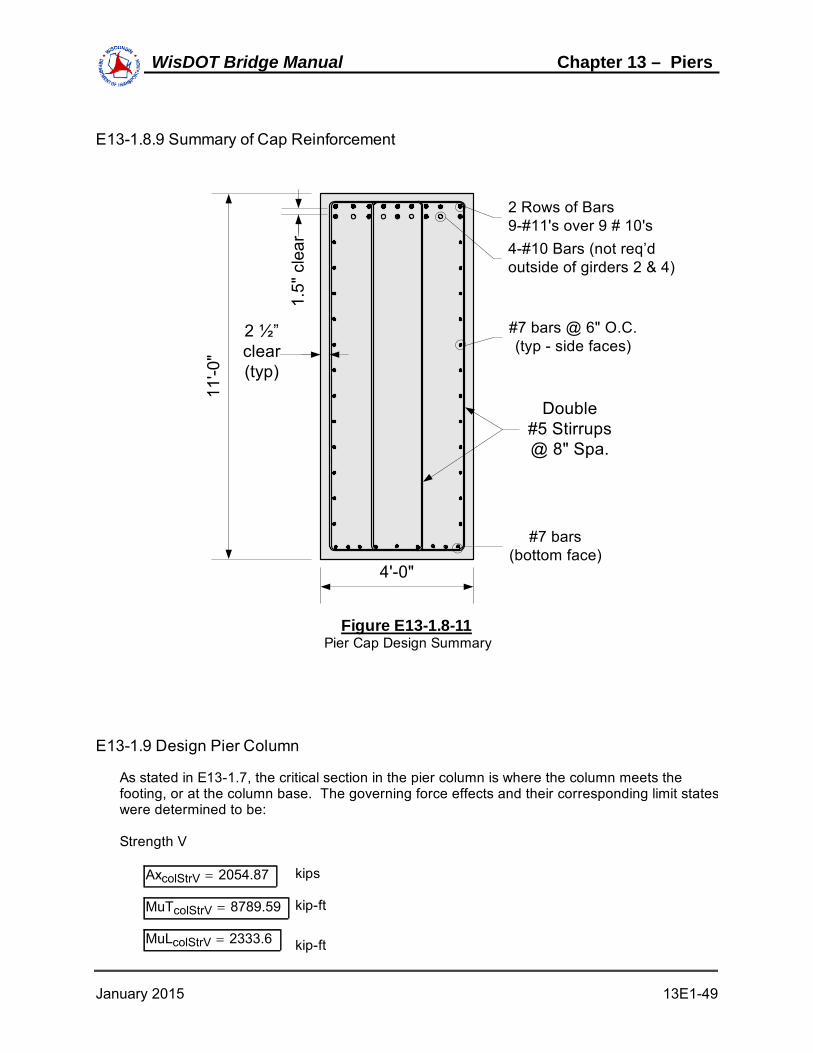
E13-1.8.9 Summary of Cap Reinforcement
#7 bars @ 6" O.C. (typ - side faces)
#7 bars(bottom face)
11'-0
"
2 ½”clear (typ)
Double#5 Stirrups@ 8" Spa.
4-#10 Bars (not req’doutside of girders 2 & 4)
2 Rows of Bars9-#11's over 9 # 10's
1.5
" cl
ear
4'-0"
Figure E13-1.8-11Pier Cap Design Summary
E13-1.9 Design Pier Column
As stated in E13-1.7, the critical section in the pier column is where the column meets thefooting, or at the column base. The governing force effects and their corresponding limit stateswere determined to be:
Strength V
AxcolStrV 2054.87 kips
MuTcolStrV 8789.59 kip-ft
MuLcolStrV 2333.6 kip-ft
January 2015 13E1-49
WisDOT Bridge Manual Chapter 13 – Piers

Strength III
VuTcol 76.45 kips
Strength V
VuLcol 105.37 kips
A preliminary estimate of the required section size and reinforcement is shown in FigureE13-1.9-1.
15'-6"
X X
Y
Y
2 1/2"
4'-0
"
#4 hoops @ 12" O.C.
#10 bars (typ)
30 Equal Spaces
7 E
qual
S
pace
s
Figure E13-1.9-1Preliminary Pier Column Design
E13-1.9.1 Design for Axial Load and Biaxial Bending (Strength V):
The preliminary column reinforcing is show in Figure E13-1.9-1 and corresponds to #10 barsequally spaced around the column perimeter. LRFD [5.7.4.2] prescribes limits (both maximumand minimum) on the amount of reinforcing steel in a column. These checks are performed onthe preliminary column as follows:
Num_bars 74 bar_area10 1.27 in2 bar_dia10 1.27 in
As_col Num_bars( ) bar_area10( )As_col 93.98 in2
Ag_col Wcol Lcol 122 Ag_col 8928 in2
As_col
Ag_col0.0105 0.0105 0.08 OK
As_col fy
Ag_col f'c0.180 0.180 0.135 OK
January 2015 13E1-50
WisDOT Bridge Manual Chapter 13 – Piers

The column slenderness ratio (Klu/r) about each axis of the column is computed below in order
to assess slenderness effects. Note that the Specifications only permit the followingapproximate evaluation of slenderness effects when the slenderness ratio is below 100.
For this pier, the unbraced lengths (lux, luy) used in computing the slenderness ratio about each
axis is the full pier height. This is the height from the top of the footing to the top of the piercap (26 feet). The effective length factor in the longitudinal direction, Kx, is taken equal to 2.1.
This assumes that the superstructure has no effect on restraining the pier from buckling. Inessence, the pier is considered a free-standing cantilever in the longitudinal direction. Theeffective length factor in the transverse direction, Ky, is taken to equal 1.0.
The radius of gyration (r) about each axis can then be computed as follows:
IxxLcol 12 Wcol 12 3
12 Ixx 1714176 in4
IyyWcol 12 Lcol 12 3
12 Iyy 25739424 in4
rxxIxx
Ag_col rxx 13.86 in
ryyIyy
Ag_col ryy 53.69 in
The slenderness ratio for each axis now follows:
Kx 2.1
Ky 1.0
Lu Hcol Hcap 12 Lu 312 in
Kx Lu
rxx47.28 47.28 100 OK
Ky Lu
ryy5.81 5.81 100 OK
LRFD [5.7.4.3] permits the slenderness effects to be ignored when the slenderness ratio isless than 22 for members not braced against side sway. It is assumed in this example that thepier is not braced against side sway in either its longitudinal or transverse directions.Therefore, slenderness will be considered for the pier longitudinal direction only (i.e., about the"X-X" axis).
In computing the amplification factor that is applied to the longitudinal moment, which is the endresult of the slenderness effect, the column stiffness (EI) about the "X-X" axis must be defined.
January 2015 13E1-51
WisDOT Bridge Manual Chapter 13 – Piers

In doing so, the ratio of the maximum factored moment due to permanent load to the maximumfactored moment due to total load must be identified (βd).
From Design Step E13-1.7, it can be seen that the force effects contributing to the longitudinalmoment are the live load braking force, the temperature force and wind on the structure andlive load. None of these are permanent or long-term loads. Therefore, βd is taken equal to
zero for this design.
βd 0
Ec 33000 wc1.5 f'c Ec 3587 ksi
Es 29000.00 ksi
Ixx 1714176 in4
Is = Moment of Inertia of longitudinal steel about the centroidal axis (in4)
Isπ bar_dia10
464
Num_bars( ) 2 31 bar_area10( ) 20.372
4 bar_area10( ) 14.552 4 bar_area10( ) 8.73
2 4 bar_area10( ) 2.912
Is 34187 in4
The column stiffness is taken as the greater of the following two calculations:
EI1
Ec Ixx
5Es Is
1 βd
EI1 2.22 109 k-in2
EI2
Ec Ixx
2.5
1 βd
EI2 2.46 109 k-in2
EI max EI1 EI2 EI 2.46 109 k-in2
The final parameter necessary for the calculation of the amplification factor is the phi-factor forcompression. This value is defined as follows:
ϕaxial 0.75
It is worth noting at this point that when axial load is present in addition to flexure, LRFD[5.5.4.2.1] permits the value of phi to be increased linearly to the value for flexure (0.90) as thesection changes from compression controlled to tension controlled as defined in LRFD[5.7.2.1]. However, certain equations in the Specification still require the use of the phi factorfor axial compression (0.75) even when the increase just described is permitted. Therefore, forthe sake of clarity in this example, if phi may be increased it will be labeled separately fromϕaxial identified above.
January 2015 13E1-52
WisDOT Bridge Manual Chapter 13 – Piers

Ascol 2.53 in2 per foot, based on #10 bars at 6-inch spacing
b 12 inches
aAscol fy
0.85 f'c b a 4.25 inches
β1 0.85
ca
β1
c 5.00 inches
dt Wcol 12 Coverco 0.5bar_dia10
2 dt 44.37 inches
εc 0.002 Upper strain limit for compression controlled sections, fy = 60 ksi LRFD[TableC5.7.2-1]εt 0.005 Lower strain limit for tension controlled sections, for fy = 60 ksi
= 0.003
d t
c
T
C
εc
εts
Figure E13-1.9-2Strain Limit Tension Control Check
εtsεc
cdt c εts 0.016 > εt = 0.005
Therefore, the section is tension controlled and phi shall be equal to 0.9.
January 2015 13E1-53
WisDOT Bridge Manual Chapter 13 – Piers

ϕt 0.9
The longitudinal moment magnification factor will now be calculated as follows:
Peπ
2EI
Kx Lu 2 Pe 56539.53 kips
δs1
1AxcolStrV
ϕt Pe
δs 1.04
The final design forces at the base of the column for the Strength I limit state will be redefinedas follows:
Pu_col AxcolStrV Pu_col 2054.87 kips
Mux MuLcolStrV δs Mux 2431.8 kip-ft
Muy MuTcolStrV Muy 8789.59 kip-ft
The assessment of the resistance of a compression member with biaxial flexure for strengthlimit states is dependent upon the magnitude of the factored axial load. This value determineswhich of two equations provided by the Specification are used.
If the factored axial load is less than ten percent of the gross concrete strength multiplied bythe phi-factor for compression members (ϕaxial), then the Specifications require that a linear
interaction equation for only the moments is satisfied (LRFD [Equation 5.7.4.5-3]). Otherwise,an axial load resistance (Prxy) is computed based on the reciprocal load method (LRFD[Equation 5.7.4.5-1]). In this method, axial resistances of the column are computed (usingfLow_axial if applicable) with each moment acting separately (i.e., Prx with Mux, Pry with Muy).
These are used along with the theoretical maximum possible axial resistance (Po multiplied by
ϕaxial) to obtain the factored axial resistance of the biaxially loaded column.
Regardless of which of the two equations mentioned in the above paragraph controls,commercially available software is generally used to obtain the moment and axial loadresistances.
For this pier design, the procedure as discussed above is carried out as follows:
0.10 ϕaxial f'c Ag_col 2343.6 kips
Pu_col 2054.87 kips Pu_col 2343.6K
Therefore, LRFD [Equation 5.7.4.5-3] will be used.
January 2015 13E1-54
WisDOT Bridge Manual Chapter 13 – Piers

Mux 2431.8 kip-ft Muy 8789.59 kip-ft
The resultant moment equals:
Mu Mux2
Muy2 Mu 9119.79 kip-ft
Mr 24052.3 kip-ft
Mu
Mr0.38 0.38 1.0 OK
The factored flexural resistances shown above, Mr, was obtained by the use of commercial
software. This value is the resultant flexural capacity assuming that no axial load is present.Consistent with this, the phi-factor for flexure (0.90) was used in obtaining the factoredresistance from the factored nominal strength.
Although the column has a fairly large excess flexural capacity, a more optimal design will notbe pursued per the discussion following the column shear check.
E13-1.9.2 Design for Shear (Strength III and Strength V)
The maximum factored transverse and longitudinal shear forces were derived in E13-1.7 andare as follows:
VuTcol 76.45 kips (Strength III)
VuLcol 105.37 kips (Strength V)
These maximum shear forces do not act concurrently. Although a factored longitudinal shearforce is present in Strength III and a factored transverse shear force is present in Strength V,they both are small relative to their concurrent factored shear. Therefore, separate sheardesigns can be carried out for the longitudinal and transverse directions using only themaximum shear force in that direction.
For the pier column of this example, the maximum factored shear in either direction is less thanone-half of the factored resistance of the concrete. Therefore, shear reinforcement is notrequired. This is demonstrated for the longitudinal direction as follows:
bv Lcol 12 bv 186 in
h Wcol 12 h 48 in
Conservatively, dv may be calculated as shown below, LRFD [5.8.2.9].
dv 0.72( ) h( ) dv 34.56 in
The above calculation for dv is simple to use for columns and generally results in a
conservative estimate of the shear capacity.
January 2015 13E1-55
WisDOT Bridge Manual Chapter 13 – Piers

β 2.0 θ 45deg
The nominal concrete shear strength is:
Vc 0.0316 β f'c bv dvVc 760.04 kips
The nominal shear strength of the column is the lesser of the following two values:
Vn1 Vc Vn1 760.04 kips
Vn2 0.25 f'c bv dv Vn2 5624.64 kips
Vn min Vn1 Vn2 Vn 760.04 kips
The factored shear resistance is:
ϕv 0.90
Vr ϕv Vn Vr 684.04 kips
Vr
2342.02 kips
VuLcol 105.37 kipsVr
2VuLcol
check "OK"
It has just been demonstrated that transverse steel is not required to resist the applied factoredshear forces. However, transverse confinement steel in the form of hoops, ties or spirals isrequired for compression members. In general, the transverse steel requirements for shearand confinement must both be satisfied per the Specifications.
It is worth noting that although the preceding design checks for shear and flexure show thecolumn to be over designed, a more optimal column size will not be pursued. The reason forthis is twofold: First, in this design example, the requirements of the pier cap dictate the columndimensions (a reduction in the column width will increase the moment in the pier cap).Secondly, a short, squat column such as the column in this design example generally has arelatively large excess capacity even when only minimally reinforced.
E13-1.9.3 Transfer of Force at Base of Column
The provisions for the transfer of forces and moments from the column to the footing are newto the AASHTO LRFD Specifications. In general, standard engineering practice for bridge piersautomatically satisfies most, if not all, of these requirements.
In this design example, and consistent with standard engineering practice, all steel reinforcingbars in the column extend into, and are developed, in the footing (see Figure E13-1.12-1).
January 2015 13E1-56
WisDOT Bridge Manual Chapter 13 – Piers

This automatically satisfies the following requirements for reinforcement across the interface ofthe column and footing: A minimum reinforcement area of 0.5 percent of the gross area of thesupported member, a minimum of four bars, and any tensile force must be resisted by thereinforcement. Additionally, with all of the column reinforcement extended into the footing,along with the fact that the column and footing have the same compressive strength, a bearingcheck at the base of the column and the top of the footing is not applicable.
In addition to the above, the Specifications require that the transfer of lateral forces from thepier to the footing be in accordance with the shear-transfer provisions of LRFD [5.8.4]. Withthe standard detailing practices for bridge piers previously mentioned (i.e., all columnreinforcement extended and developed in the footing), along with identical design compressivestrengths for the column and footing, this requirement is generally satisfied. However, for thesake of completeness, this check will be carried out as follows:
Acv Ag_col Area of concrete engagedin shear transfer.
Acv 8928 in2
Avf As_col Area of shear reinforcementcrossing the shear plane.
Avf 93.98 in2
For concrete placed against a clean concrete surface, not intentionally roughened, thefollowing values are obtained from LRFD [5.8.4.3].
ccv 0.075 Cohesion factor, ksi
μ 0.60 Friction factor
K1 0.2
K2 0.8
The nominal shear-friction capacity is the smallest of the following three equations(conservatively ignore permanent axial compression):
Vnsf1 ccv Acv μ Avf fy Vnsf1 4052.88 kips
Vnsf2 K1 f'c Acv Vnsf2 6249.6 kips
Vnsf3 K2 Acv Vnsf3 7142.4 kips
Define the nominal shear-friction capacity as follows:
Vnsf min Vnsf1 Vnsf2 Vnsf3 Vnsf 4052.88 kips
The maximum applied shear was previously identified from the Strength V limit state:
VuLcol 105.37 kips
It then follows:
January 2015 13E1-57
WisDOT Bridge Manual Chapter 13 – Piers

ϕv 0.9
ϕv Vnsf 3647.59 kips
ϕv Vnsf VuLcol
check "OK"
As can be seen, a large excess capacity exists for this check. This is partially due to the factthat the column itself is over designed in general (this was discussed previously). However, thehorizontal forces generally encountered with common bridges are typically small relative to theshear-friction capacity of the column (assuming all reinforcing bars are extended into thefooting). In addition, the presence of a shear-key, along with the permanent axial compressionfrom the bridge dead load, further increase the shear-friction capacity at the column/footinginterface beyond that shown above.
E13-1.10 Design Pier Piles
The foundation system for the pier is a reinforced concrete footing on steel H-piles. TheHP12x53 pile layout used for this pier foundation is shown in Figure E13-1.10-1.
Based on the given pile layout, the controlling limit states for the pile design were given inE13-1.7.3.
January 2015 13E1-58
WisDOT Bridge Manual Chapter 13 – Piers

X X
Y
Y
1'-6" 5'-0" 5'-0" 5'-0" 5'-0" 1'-6"
1'-6
"3'
-0"
3'-0
"3'
-0"
1'-6
"
3'-9"
Ahead Station
12'-0
"
16
11
6
1
17
12
7
2
18
13
8
3
19
14
9
4
20
15
10
5
4'-0
"
23'-0"
Figure E13-1.10-1Pier Pile Layout
Np 20 Number of piles
Sxx10 4.5
2 10 1.52
4.5 Sxx 50 ft3
Syy8 10
2 8 52
10 Syy 100 ft3
Maximum pile reaction:
ϕt 0.9
Pe 56539.53 kips (from column design)
Pu2pile_Str1 3179.17 kips
MuT2pile_Str1 7836.85 kip-ft
MuL2pile_Str1 1856.29 kip-ft
January 2015 13E1-59
WisDOT Bridge Manual Chapter 13 – Piers

δpile_StrI1
1Pu2pile_Str1
ϕt Pe
δpile_StrI 1.07
PupPu2pile_Str1
Np
MuT2pile_Str1
Syy
MuL2pile_Str1 δpile_StrI
Sxx
Pup 276.93 kips
Pup_tonsPup
2 Pup_tons 138.46 tons
From Wis Bridge Manual, Section 11.3.1.17.6, the vertical pile resistance of HP12x53 pile is :
Pr12x53 139.5 tonscheck "OK"
Minimum pile reaction (Strength V):
Pupile_StrV 2134.91 kips
MuTpile_StrV 7670.61 kip-ft
MuLpile_StrV 2333.6 kip-ft
δpile_StrV1
1Pupile_StrV
ϕt Pe
δpile_StrV 1.04
Pumin_pPupile_StrV
Np
MuTpile_StrV
Syy
MuLpile_StrV δpile_StrV
Sxx
Pumin_p 18.68 kips
Capacity for pile uplift is site dependant. Consult with the geotechnical engineer for allowablevalues.
The horizontal pile resistance of HP12x53 pile from the soils report is :
Hr12x53 14 kips/pile
January 2015 13E1-60
WisDOT Bridge Manual Chapter 13 – Piers

Pile dimensions in the transverse (xx) and longitudinal (yy) directions:
Bxx 12.05 inches
Byy 11.78 inches
Pile spacing in the transverse and longitudinal directions:
Spaxx 5.0 feetSpaxx
Bxx
12
4.98 Say: 5B
Spayy 3.0 feetSpayy
Byy
12
3.06 Say: 3B
Use the pile multipliers from LRFD [T-10.7.2.4-1] to calculate the group resistance of the pilesin each direction.
Hrxx Hr12x53 4 1.0 0.85 0.70 3( ) Hrxx 221.2 kips
HuTpileStrIII 76.45 kips
Hrxx > HuT
check "OK"
Hryy Hr12x53 5 0.7 0.5 0.35 2( ) Hryy 133 kips
HuLpileStrV 105.37 kips
Hryy > HuL
check "OK"
January 2015 13E1-61
WisDOT Bridge Manual Chapter 13 – Piers

E13-1.11 - Design Pier Footing
In E13-1.7, the Strength I limit states was identified as the governing limit state for the design ofthe pier footing.
Listed below are the Strength I footing loads for one, two and three lanes loaded:
Pu1ftgStr1 2643.74 kips Pu2ftgStr1 2928.7 kips
MuT1ftgStr1 7267.81 kip-ft MuT2ftgStr1 7836.85 kip-ft
MuL1ftgStr1 1187.7 kip-ft MuL2ftgStr1 1856.29 kip-ft
Pu3ftgStr1 3124.66 kips
MuT3ftgStr1 4541.55 kip-ft
MuL3ftgStr1 2315.94 kip-ft
The longitudinal moment given above must be magnified to account for slenderness of thecolumn (see E13-1.9). The computed magnification factor and final factored forces are:
δs1_ftgStr11
1Pu1ftgStr1
ϕt Pe
δs1_ftgStr1 1.05
δs2_ftgStr11
1Pu2ftgStr1
ϕt Pe
δs2_ftgStr1 1.06
δs3_ftgStr11
1Pu3ftgStr1
ϕt Pe
δs3_ftgStr1 1.07
MuL1ftgStr1δ δs1_ftgStr1 MuL1ftgStr1 MuL1ftgStr1δ 1252.79 kip-ft
MuL2ftgStr1δ δs2_ftgStr1 MuL2ftgStr1 MuL2ftgStr1δ 1969.65 kip-ft
MuL3ftgStr1δ δs3_ftgStr1 MuL3ftgStr1 MuL3ftgStr1δ 2467.46 kip-ft
January 2015 13E1-62
WisDOT Bridge Manual Chapter 13 – Piers

The calculations for the Strength I pile loads on the footing are calculated below for one, twoand three lanes loaded.
Np 20 Number of piles
Sxx 50 ft3
Syy 100 ft3
The following illustrates the corner pile loads for 2 lanes loaded:
Pu21Pu2ftgStr1
Np
MuT2ftgStr1
Syy
MuL2ftgStr1δ
Sxx Pu21 264.2
Pu25Pu2ftgStr1
Np
MuT2ftgStr1
Syy
MuL2ftgStr1δ
Sxx Pu25 107.46
Pu216Pu2ftgStr1
Np
MuT2ftgStr1
Syy
MuL2ftgStr1δ
Sxx Pu216 185.41
Pu220Pu2ftgStr1
Np
MuT2ftgStr1
Syy
MuL2ftgStr1δ
Sxx
Pu220 28.67
Pile loads between the corners can be interpolated. Similar calculations for the piles for thecases of one, two and three lanes loaded produce the following results:
January 2015 13E1-63
WisDOT Bridge Manual Chapter 13 – Piers

Pu1
229.92
213.22
196.51
179.81
193.58
176.88
160.17
143.47
157.24
140.54
123.84
107.13
120.9
104.2
87.5
70.79
84.56
67.86
51.16
34.45
Pu2
264.2
237.93
211.67
185.41
225.01
198.75
172.49
146.23
185.83
159.57
133.3
107.04
146.64
120.38
94.12
67.86
107.46
81.2
54.94
28.67
Pu3
251
218.1
185.2
152.3
228.29
195.39
162.49
129.59
205.58
172.68
139.78
106.88
182.87
149.97
117.08
84.18
160.17
127.27
94.37
61.47
Pu1pile 229.92 Pu2pile 264.2 Pu3pile 251
A conservative simplification is to use the maximum pile reaction for all piles when calculatingthe total moment and one way shear forces on the footing.
Pu max Pu1pile Pu2pile Pu3pile Pu 264.2 kips
E13-1.11.1 Design for Moment
The footing is designed for moment using the pile forces computed above on a per-foot basisacting on each footing face. The design section for moment is at the face of the column. Thefollowing calculations are based on the outer row of piles in each direction, respectively.
Lftg_xx Lftg Lftg_xx 23 feet
Lftg_yy Wftg Wftg 12 feet
Applied factored load per foot in the "X" direction:
PuMom_xx Pu 5 PuMom_xx 1320.98 kips
January 2015 13E1-64
WisDOT Bridge Manual Chapter 13 – Piers

RxxPuMom_xx
Lftg_xx Rxx 57.43 kips per foot
Estimation of applied factored load per foot in the "Y" direction:
PuMom_yy Pu 4 PuMom_yy 1056.79 kips
RyyPuMom_yy
Lftg_yy Ryy 88.07 kips per foot
armxx 2.5 feet
armyy 2.25 feet
The moment on a per foot basis is then:
Muxx Rxx armxx Muxx 143.59 kip-ft perfoot
Muyy Ryy armyy Muyy 198.15 kip-ft perfoot
Once the maximum moment at the critical section is known, flexure reinforcement must bedetermined. The footing flexure reinforcement is located in the bottom of the footing and restson top of the piles.
Assume #8 bars:
bar_diam8 1.0 inches
bar_area8 0.79 in2
fy 60 ksi
The footing minimum tensile reinforcement requirements will be calculated. The tensilereinforcement provided must be enough to develop a factored flexural resistance at least equalto the lesser of the cracking strength or 1.33 times the factored moment from the applicablestrength load combinations, LRFD [5.7.3.3.2].
The cracking strength is calculated as follows, LRFD[5.7.3.3.2]:
January 2015 13E1-65
WisDOT Bridge Manual Chapter 13 – Piers

Centroidal Axis
Top offooting
Trans Reinf #8 bars
1'-0"
3'-6
"
6 ½
”1'
-9"
Longit Reinf #8 bars
Figure E13-1.11-1Footing Cracking Moment Dimensions
fr 0.24 f'c fr 0.45 ksi
Sgb Hftg 12 2
6 Sg 3528 in4
ytHftg 12
2 yt 21 in
Mcr γ3 γ1 fr Sg= therefore, Mcr 1.1 fr Sg=
Where:
γ1 1.6 flexural cracking variability factor
γ3 0.67 ratio of yield strength to ultimate tensile strength of the reinforcement for A615, Grade 60 reinforcement
Mcr 1.1fr Sg1
12 Mcr 145.21 kip-ft
1.33 times the factored controlling footing moment is:
January 2015 13E1-66
WisDOT Bridge Manual Chapter 13 – Piers

Muftg max Muxx Muyy Muftg 198.15 kip-ft
1.33 Muftg 263.54 kip-ft
MDesign min Mcr 1.33 Muftg MDesign 145.21 kip-ft
Muftg exceeds MDesign , therefore set MDesign = Muftg
Since the transverse moment controlled, Myy, detail the transverse reinforcing to be located
directly on top of the piles.
Effective depth, de = total footing thickness - cover - 1/2 bar diameter
de Hftg 12 Coverfbbar_diam8
2
de 35.5 in
Solve for the required amount of reinforcing steel, as follows:
ϕf 0.90
b 12 in
f'c 3.5 ksi
RnMDesign 12
ϕf b de2
Rn 0.175
ρ 0.85f'c
fy
1.0 1.02 Rn
0.85 f'c
ρ 0.00300
Asftg ρ b de Asftg 1.28 in2 per foot
Required bar spacing =bar_area8
Asftg12 7.41 in
Use #8 bars @ bar_space 7
Asftg bar_area812
bar_space
Asftg 1.35 in2 per foot
check "OK"
Similar calculations can be performed for the reinforcing in the longitudinal direction. Theeffective depth for this reinforcing is calculated based on the longitudinal bars resting directlyon top of the transverse bars.
January 2015 13E1-67
WisDOT Bridge Manual Chapter 13 – Piers

E13-1.11.2 Punching Shear Check
The factored force effects from E13-1.7 for the punching shear check at the column are:
Pu3ftgStr1 3124.66 kips
MuT3ftgStr1 4541.55 kip-ft
MuL3ftgStr1δ 2467.46 kip-ft
Pu3
251
218.1
185.2
152.3
228.29
195.39
162.49
129.59
205.58
172.68
139.78
106.88
182.87
149.97
117.08
84.18
160.17
127.27
94.37
61.47
Pu3pile 251 kips
With the applied factored loads determined, the next step in the column punching shear checkis to define the critical perimeter, bo. The Specifications require that this perimeter be
minimized, but need not be closer than dv/2 to the perimeter of the concentrated load area. In
this case, the concentrated load area is the area of the column on the footing as seen in plan.
The effective shear depth, dv, must be defined in order to determine bo and the punching (or
two-way) shear resistance. An average effective shear depth should be used since thetwo-way shear area includes both the "X-X" and "Y-Y" sides of the footing. In other words, dex
is not equal to dey, therefore dvx will not be equal to dvy. This is illustrated as follows assuming
a 3'-6" footing with #8 reinforcing bars at 6" on center in both directions in the bottom of thefooting:
b 12 in
hftg Hftg 12hftg 42 in
As_ftg 2 bar_area8( ) As_ftg 1.58 in2 per foot width
Effective depth for each axis:
Coverfb 6
dey hftg Coverfbbar_diam8
2
dey 35.5 in
dex hftg Coverfb bar_diam8bar_diam8
2 dex 34.5 in
January 2015 13E1-68
WisDOT Bridge Manual Chapter 13 – Piers

Effective shear depth for each axis:
Tftg As_ftg fy Tftg 94.8 kips
aftgTftg
0.85 f'c b aftg 2.66 in
dvx max dexaftg
2 0.9 dex 0.72 hftg
dvx 33.17 in
dvy max deyaftg
2 0.9 dey 0.72 hftg
dvy 34.17 in
Average effective shear depth:
dv_avgdvx dvy
2 dv_avg 33.67 in
With the average effective shear depth determined, the critical perimeter can be calculated asfollows:
bcol Lcol 12 bcol 186 in
tcol Wcol 12 tcol 48 in
bo 2 bcol 2dv_avg
2
2 tcol 2dv_avg
2
bo 602.69 in
The factored shear resistance to punching shear is the smaller of the following two computedvalues:
βcbcol
tcol βc 3.88
Vn_punch1 0.0630.126
βc
f'c bo dv_avg Vn_punch1 3626.41 kips
Vn_punch2 0.126 f'c bo dv_avg Vn_punch2 4783.77 kips
Vn_punch min Vn_punch1 Vn_punch2 Vn_punch 3626.41 kips
ϕv 0.9
Vr_punch ϕv Vn_punch Vr_punch 3263.77 kips
With the factored shear resistance determined, the applied factored punching shear load willbe computed. This value is obtained by summing the loads in the piles that are outside of thecritical perimeter. As can be seen in Figure E13-1.11-2, this includes Piles 1 through 5, 6,10,11, 15, and 16 through 20. These piles are entirely outside of the critical perimeter. If part
January 2015 13E1-69
WisDOT Bridge Manual Chapter 13 – Piers

of a pile is inside the critical perimeter, then only the portion of the pile load outside the criticalperimeter is used for the punching shear check, LRFD [5.13.3.6.1].
tcol
2
dv_avg
2
1
12 3.4 feet
X X
Y
Y
Critical Perimeter for Column Punching Shear
Column Perimeter
+Mux
+Muy
dv/
2
16
11
6
1
17
12
7
2
18
13
8
3
19
14
9
4
20
15
10
5
Figure E13-1.11-2Critical Perimeter for Column Punching Shear
The total applied factored shear used for the punching shear check is the sum of the pilesoutside of the shear perimeter (1 through 5, 6, 10, 11, 15 and 16 through 20):
Vu_punch max Pu1punch_col Pu2punch_col Pu3punch_col
Vu_punch 2187.26 kips
Vr_punch 3263.77 kips
Vu_punch Vr_punch
check "OK"
For two-way action around the maximum loaded pile, the pile critical perimeter, bo, is located a
minimum of 0.5dv from the perimeter of the pile. If portions of the critical perimeter are located
off the footing, that portion of the critical perimeter is limited by the footing edge.
January 2015 13E1-70
WisDOT Bridge Manual Chapter 13 – Piers

Two-way action should be checked for the maximum loaded pile, The effective shear depth, dv
is the same as that used for the punching shear check for the column.
Vu2way Pu2pile Vu2way 264.2 kips
dv_avg 33.67 in
0.5 dv_avg 16.84 in
Two-way action or punching shear resistance for sections without transverse reinforcement canthen be calculated as follows:
Vn 0.0630.126
βc
f'c bo dv 0.126 f'c bo dv=
Bxx 12.05 in
Byy 11.78 in
HP12x53
1
Pile critical perimeter
1'-6"
1'-6
"
Byy
/2d v
/2
dv/2Bxx/2
Figure E13-1.11-3Pile Two-way Action Critical Perimeter
Since the critical section is outside of the footing, only include the portion of the shearperimeter that is located within the footing:
bo_xx 1.5 12Bxx
2
dv_avg
2
bo_xx 40.86 in
bo_yy 1.5 12Byy
2
dv_avg
2 bo_yy 40.73 in
January 2015 13E1-71
WisDOT Bridge Manual Chapter 13 – Piers

Ratio of long to short side of critical perimeter:
βc_pilebo_xx
bo_yy βc_pile 1.003
bo_pile bo_xx bo_yy bo_pile 81.59 in
Vn_pile1 0.0630.126
βc_pile
f'c bo_pile dv_avg Vn_pile1 969.24 kips
Vn_pile2 0.126 f'c bo_pile dv_avg Vn_pile2 647.59 kips
Vn_pile min Vn_pile1 Vn_pile2 Vn_pile 647.59 kips
ϕv 0.9
Vr_pile ϕv Vn_pile Vr_pile 582.83 kips
Vu2way 264.2 kips
Vr_pile > Vu2way
check "OK"
E13-1.11.3 One Way Shear Check
Design for one way shear in both the transverse and longitudinal directions.
For one way action in the pier footing, in accordance with LRFD[5.13.3.6.1] & [5.8.3.2] thecritical section is taken as the larger of:
0.5 dv cotθ or dv
θ 45deg
The term dv is calculated the same as it is for the punching shear above:
dvx 33.17 in
dvy 34.17 in
Now the critical section can be calculated:
dvxx max 0.5 dvx cot θ( ) dvx dvxx 33.17 in
dvyy max 0.5 dvy cot θ( ) dvy dvyy 34.17 in
January 2015 13E1-72
WisDOT Bridge Manual Chapter 13 – Piers

Distance from face of column to CL of pile in longitudinal and transverse directions:
armxx 2.5 feet
armyy 2.25 feet
Distance from face of column to outside edge of pile in longitudinal and transverse directions:
> dvx, design check requiredarmxx 12
Byy
2 35.89
< dvy, no design check requiredarmyy 12
Bxx
2 33.02
X X
Y
Y
Critical Location for One-Way Shear
Column Perimeter
+Mux
+Muy
16
11
6
1
17
12
7
2
18
13
8
3
19
14
9
4
20
15
10
5
d vx
dvy
Figure E13-1.11-4Critical Section for One-Way Shear
Portion of pile outside of the critical section for one way shear in the longitudinal direction:
bxx armxx 12Byy
2 dvx bxx 2.72 inches
The load applied to the critical section will be based on the proportion of the pile locatedoutside of the critical section. As a conservative estimate, the maximum pile reaction will beassumed for all piles.
January 2015 13E1-73
WisDOT Bridge Manual Chapter 13 – Piers

Pu 264.2 kips
Pu1wayx Pu 5 Pu1wayx 1320.98 kips
Vu1wayx Pu1wayxbxx
Byy Vu1wayx 304.76 kips
The nominal shear resistance shall be calculated in accordance with LRFD [5.8.3.3] and is thelesser of the following:
β1way 2.0
bv Lftg 12 bv 276 inches
Vn_1way1 0.0316 β1way f'c bv dvx Vn_1way1 1082.52 kips
Vn_1ay2 0.25 f'c bv dvx Vn_1ay2 8011.1 kips
Vn_1way min Vn_1way1 Vn_1ay2 Vn_1way 1082.52 kips
ϕv 0.9
Vr_1way ϕv Vn_1way Vr_1way 974.27 kips
Vu1wayx 304.76 kips
Vr_1way > Vu1wayx
check "OK"
January 2015 13E1-74
WisDOT Bridge Manual Chapter 13 – Piers

E13-1.12 Final Pier Schematic
Figure E13-1.12-1 shows the final pier dimensions along with the required reinforcement in thepier cap and column.
Double #5 Stirrups @ 8" spa. (typ.)
5'-0
"6'
-0"
15'
-0"
46'-6"
3'-6
"
23'-0"
9 - #11 bars
74 - #10 bars equally spaced around
column perimeter #4
stirr
ups
@ 1
2"
spa
cing
(ty
p)
15'-6"
#7 bars @ 6" spa.
#7
ba
rs @
6"
sp
a.
5 - #10 bars4 - #10 bars
#5 U-bars
Figure E13-1.12-1Final Pier Design
January 2015 13E1-75
WisDOT Bridge Manual Chapter 13 – Piers

WisDOT Bridge Manual
This page intentionally left blank.

Table of ContentsE13-2 Multi-Column Pier Design Example LRFD.........................................................................................
E13-2.1 Obtain Design Criteria ..........................................................................................E13-2.1.1 Material Properties:...............................................................................E13-2.1.2 Reinforcing steel cover requirements (assume epoxy coated bars) ...E13-2.1.3 Relevant Superstructure Data ..............................................................E13-2.1.4 Select Optimum Pier Type....................................................................E13-2.1.5 Select Preliminary Pier Dimensions......................................................
E13-2.2 Loads ....................................................................................................................E13-2.2.1 Superstructure Dead Loads..................................................................E13-2.2.2 Live Load Reactions per Design Lane..................................................E13-2.2.3 Superstructure Live Load Reactions.....................................................
E13-2.3 Unfactored Force Effects ......................................................................................E13-2.4 Load Factors.........................................................................................................E13-2.5 Combined Force Effects .......................................................................................E13-2.6 Pier Cap Design....................................................................................................
E13-2.6.1 Positive Moment Capacity Between Columns ......................................E13-2.6.2 Positive Moment Reinforcement Cut Off Location................................E13-2.6.3 Negative Moment Capacity at Face of Column ....................................E13-2.6.4 Negative Moment Reinforcement Cut Off Location ..............................E13-2.6.5 Shear Capacity at Face of Center Column ...........................................E13-2.6.6 Temperature and Shrinkage Steel ........................................................E13-2.6.7 Skin Reinforcement ..............................................................................
E13-2.7 Reinforcement Summary ......................................................................................
22233447799
121212151517202225282829
WisDOT Bridge Manual Chapter 13 – Piers

E13-2 Multi-Column Pier Design Example - LRFD 2 Span Bridge, 54W, LRFD Design
5 Spa. @ 7'-6" = 37'-6"
40'-0" Clear
This pier is designed for the superstructure as detailed in example E19-2. This is a two-spanprestressed girder grade separation structure. Semi-expansion bearings are located at theabutments, and fixed bearings are used at the pier.
120'-0” 120'-0”
240'-0”
L Bearing Abutment
L Bearing Abutment
L Pier
SEFSECCC
E13-2.1 Obtain Design Criteria
This multi-column pier design example is based on AASHTO LRFD Bridge DesignSpecifications, (Seventh Edition). The design methods presented throughout the exampleare meant to be the most widely used in general bridge engineering practice. Calculationsare only shown for the pier cap. For example column and footing calculations, see exampleE13-1.
The first design step is to identify the appropriate design criteria. This includes, but is notlimited to, defining material properties, identifying relevant superstructure information, anddetermining the required pier geometry.
|
E13-2.1.1 Material Properties:wc 0.150 Concrete density, kcf
January 2015 13E2-2
WisDOT Bridge Manual Chapter 13 – Piers

f'c 3.5 Concrete 28-day compressive strength, ksiLRFD [5.4.2.1 & Table C5.4.2.1-1]
fy 60 Reinforcement strength, ksi LRFD [5.4.3 & 6.10.1.7]
Es 29000 Modulus of Elasticity of the reinforcing steel, ksi
Ec 33000 wc1.5 f'c
Ec 3587 Modulus of Elasticity of the Concrete, ksi LRFD [5.4.2.4]
E13-2.1.2 Reinforcing steel cover requirements (assume epoxy coated bars)
Cover dimension listed below is in accordance with LRFD [Table 5.12.3-1].
Covercap 2.5 Concrete cover in pier cap, inches
E13-2.1.3 Relevant Superstructure Data
L 130 design span length, feet
wb 42.5 out to out width of deck, feet
wdeck 40 clear width of deck, feet
wp 0.387 weight of Wisconsin Type LF parapet, klf
ts 8 slab thickness, inches
thaunch 4 haunch thickness, inches
skew 0 skew angle, degrees
S 7.5 girder spacing, ft
ng 6 number of girders
DOHwb ng 1( ) S
2 deck overhang length DOH 2.5 feet
wtf 48 width of 54W girder top flange, inches
ttf 3 thickness of 54W girder top flange, inches
January 2015 13E2-3
WisDOT Bridge Manual Chapter 13 – Piers

tfslope2.5
20.75 slope of bottom surface
of top flangetfslope 0.12 feet per foot
girderH 54 height of 54W girder, inches
E13-2.1.4 Select Optimum Pier Type
Selecting the most optimal pier type depends on site conditions, cost considerations,superstructure geometry, and aesthetics. The most common pier types are single column(i.e., "hammerhead"), solid wall type, and bent type (multi-column or pile bent). For thisdesign example, a multi-column pier was chosen.
E13-2.1.5 Select Preliminary Pier DimensionsSince the Specifications do not have standards regarding maximum or minimum dimensions fora pier cap, column, or footing, the designer should base the preliminary pier dimensions onstate specific standards, previous designs, and past experience. The pier cap, however, mustbe wide enough to accommodate the bearing.
capL 41.5 overall cap length, ft
capH 4.0 pier cap height, ft
capW 3.5 pier cap width, ft
colspa 18.25 column spacing, ft
cold 3 column depth (perpendicular to pier CL), ft
colw 4 column width (parallel to pier CL), ft
colh 18 column height, ft
capOH 2.5 pier cap overhang dimension, ft
January 2015 13E2-4
WisDOT Bridge Manual Chapter 13 – Piers

7'-6"
41'-6"
4'-0"
4'-0
"3'
-0"
18'-0
"
2'-0"
18'-3"
2'-6"
9'-0"
Figures E13-2.1.3-1 and E13-2.1.3-2 show the preliminary dimensions selected for this pierdesign example.
Figure E13-2.1-1Preliminary Pier Dimensions - Front Elevation
January 2015 13E2-5
WisDOT Bridge Manual Chapter 13 – Piers

18'-0
"4'
-0" 3'-6"
9'-0"
3'-0"
Figure E13-2.1-2Preliminary Pier Dimensions - End Elevation
January 2015 13E2-6
WisDOT Bridge Manual Chapter 13 – Piers
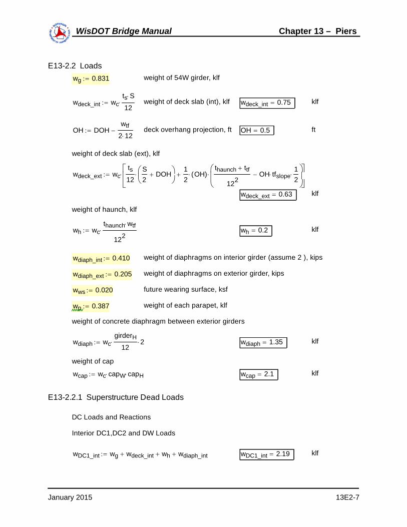
E13-2.2 Loads wg 0.831 weight of 54W girder, klf
wdeck_int wcts S
12 weight of deck slab (int), klf wdeck_int 0.75 klf
OH DOHwtf
2 12 deck overhang projection, ft OH 0.5 ft
weight of deck slab (ext), klf
wdeck_ext wcts12
S2
DOH
12
OH( )thaunch ttf
122OH tfslope
12
wdeck_ext 0.63 klf
weight of haunch, klf
wh wcthaunch wtf
122 wh 0.2 klf
wdiaph_int 0.410 weight of diaphragms on interior girder (assume 2 ), kips
wdiaph_ext 0.205 weight of diaphragms on exterior girder, kips
wws 0.020 future wearing surface, ksf
wp 0.387 weight of each parapet, klf
weight of concrete diaphragm between exterior girders
wdiaph wcgirderH
12 2 wdiaph 1.35 klf
weight of cap
wcap wc capW capH wcap 2.1 klf
E13-2.2.1 Superstructure Dead Loads
DC Loads and Reactions
Interior DC1,DC2 and DW Loads
wDC1_int wg wdeck_int wh wdiaph_int wDC1_int 2.19 klf
January 2015 13E2-7
WisDOT Bridge Manual Chapter 13 – Piers

wDC22 wp
ng wDC2 0.13 klf
wDWwws wdeck
ng wDW 0.13 klf
Interior DC and DW Reactions
RDCi12
L wDC1_int58
L wDC2
2 RDCi 305.79 kips
RDWi58
L wDW
2 RDWi 21.67 kips
Exterior DC1 Loads
wDC1_ext wg wdeck_ext wh wdiaph_ext wDC1_ext 1.86 klf
Note: DC2 and DW loads are the same for interior and exterior girders.
Exterior DC and DW Reactions
RDCe12
L wDC1_ext58
L wDC2
2 RDCe 262.98 kips
RDWe58
L wDW
2 RDWe 21.67 kips
The unfactored dead load reactions are listed below:
Girder # DC DW1 263.0 21.72 305.8 21.73 305.8 21.74 305.8 21.75 305.8 21.76 263.0 21.7
Unfactored Girder Reactions (kips)
Table E13-2.2-1Unfactored Girder Dead Load Reactions
January 2015 13E2-8
WisDOT Bridge Manual Chapter 13 – Piers
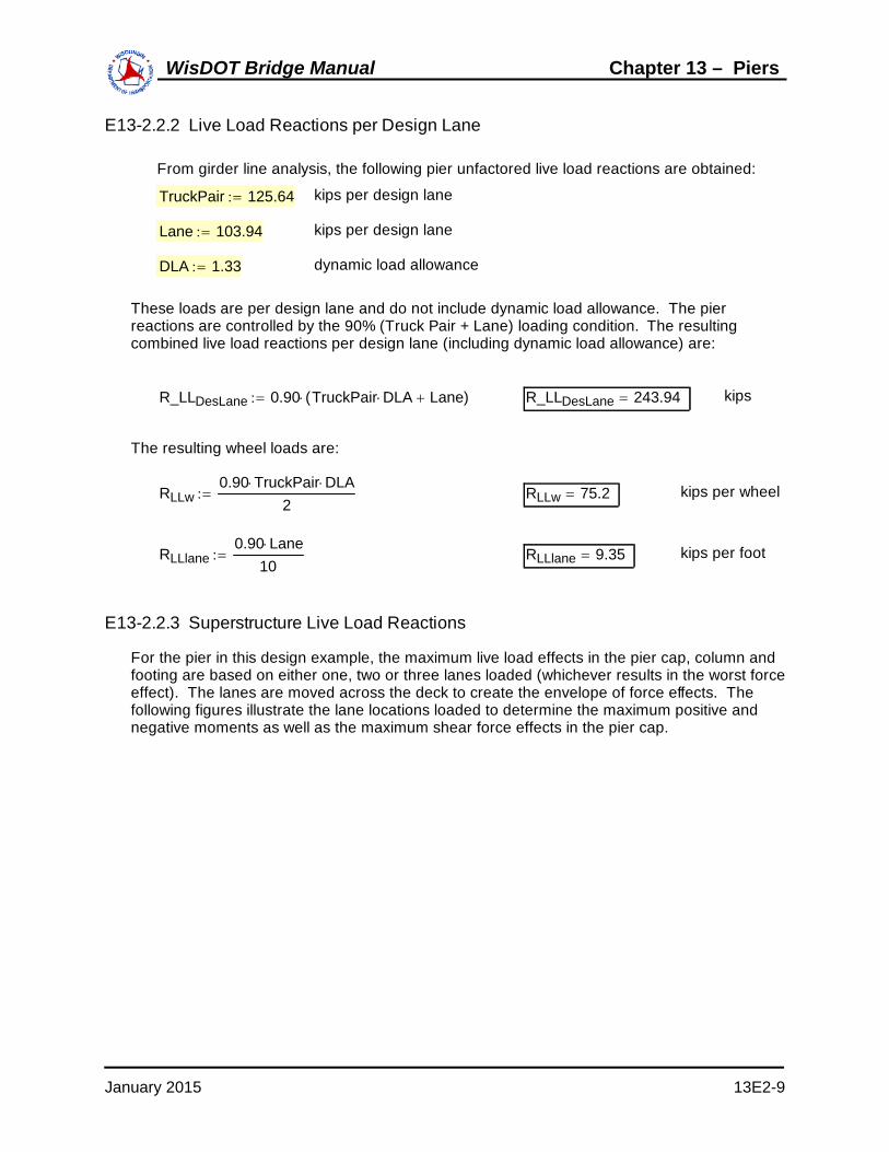
E13-2.2.2 Live Load Reactions per Design Lane
From girder line analysis, the following pier unfactored live load reactions are obtained:
TruckPair 125.64 kips per design lane
Lane 103.94 kips per design lane
DLA 1.33 dynamic load allowance
These loads are per design lane and do not include dynamic load allowance. The pierreactions are controlled by the 90% (Truck Pair + Lane) loading condition. The resultingcombined live load reactions per design lane (including dynamic load allowance) are:
R_LLDesLane 0.90 TruckPair DLA Lane( ) R_LLDesLane 243.94 kips
The resulting wheel loads are:
RLLw0.90 TruckPair DLA
2 RLLw 75.2 kips per wheel
RLLlane0.90 Lane
10 RLLlane 9.35 kips per foot
E13-2.2.3 Superstructure Live Load Reactions
For the pier in this design example, the maximum live load effects in the pier cap, column andfooting are based on either one, two or three lanes loaded (whichever results in the worst forceeffect). The lanes are moved across the deck to create the envelope of force effects. Thefollowing figures illustrate the lane locations loaded to determine the maximum positive andnegative moments as well as the maximum shear force effects in the pier cap.
January 2015 13E2-9
WisDOT Bridge Manual Chapter 13 – Piers

7'-6"
4'-0"
2'-0"
18'-3" 2'-6"
4'-6" 3'-0"7'-0" 6"
Figure E13-2.2-1Lane Locations for Maximum Positive Moment
7'-6"
4'-0"
2'-0"
18'-3" 2'-6"
4'-6" 3'-0"7'-0" 6"
5'-0"2'-6"
Figure E13-2.2-2Lane Locations for Maximum Negative Moment
January 2015 13E2-10
WisDOT Bridge Manual Chapter 13 – Piers

7'-6"
4'-0"
2'-0"
18'-3" 2'-6"
4'-6"3'-0"7'-0"6"
Figure E13-2.2-3Lane Locations for Maximum Shear
The next step is to compute the reactions due to the above loads at each of the six bearinglocations. This is generally carried out by assuming the deck is pinned (i.e., discontinuous) atthe interior girder locations but continuous over the exterior girders. Solving for the reactions isthen elementary. The computations for the reactions for maximum moment with only 2 lanesloaded are illustrated below as an example. All reactions shown are in kips.
m2 1.0 Multi-presence factor for two lanes loaded
R1LL m2 RLLw6.07.5
RLLlane 0.57.52
R1LL 99.91
R2LL m2 RLLw1.57.5
13.57.5
RLLlane 7.5( )
R2LL 195.49
R3LL m2 RLLw4.0 5.0
7.5
RLLlane7.52
4.55.257.5
R3LL 154.78
R4LL m2 RLLw2.57.5
RLLlane 4.52.257.5
R4LL 37.69
R5LL 0 R5LL 0
R6LL 0 R6LL 0
January 2015 13E2-11
WisDOT Bridge Manual Chapter 13 – Piers

E13-2.3 Unfactored Force EffectsThe resulting unfactored force effects for the load cases shown above are shown in the tablebelow. Note that the maximum shear and negative moment values are taken at the face of thecolumn.
DC DW LL Maximum Positive Moment 943.1 62.17 628.4Maximum Negative Moment -585.6 -39.03 -218.9Maximum Shear 429.2 28.53 228.3 (Corresponding Moment) -585.6 -39.03 -119.3
Unfactored Force EffectsEffect
Table E13-2.3-1Unfactored Force Effects
E13-2.4 Load Factors From LRFD [Table 3.4.11]:
DC DW LL
γstDC 1.25 γstDW 1.50 γstLL 1.75
γs1DC 1.0 γs1DW 1.0 γs1LL 1.0
E13-2.5 Combined Force Effects
The resulting factored Service and Strength force effects for the load cases previouslyillustrated are shown in the tables below. The full Service and Strength factored moment andshear envelopes are shown in the following graphs.
DC DW LL TotalMaximum Positive Moment 943.1 62.2 628.4 1633.7Maximum Negative Moment -585.6 -39.0 -218.9 -843.5Maximum Shear 429.2 28.5 228.3 686.0 (Corresponding Moment) -585.6 -39.0 -119.3 -743.9
EffectFactored Service Force Effects
Table E13-2.5-1Factored Service Force Effects
DC DW LL TotalMaximum Positive Moment 1178.9 93.3 1099.7 2371.8Maximum Negative Moment -732.0 -58.5 -383.1 -1173.6Maximum Shear 536.5 42.8 399.5 978.8 (Corresponding Moment) -732.0 -58.5 -208.8 -999.3
EffectFactored Strength Force Effects
Table E13-2.5-2Factored Strength I Force Effects
January 2015 13E2-12
WisDOT Bridge Manual Chapter 13 – Piers

0 10 20 30 40
3 103
2 103
1 103
1 103
2 103
Factored Service Moments
Distance Along Cap (ft)
Serv
ice
Mom
ent (
kip-
ft)
0 10 20 30 40
1 103
500
500
1 103
Factored Service Shear
Distance Along Cap (ft)
Serv
ice
Shea
r (ki
ps)
January 2015 13E2-13
WisDOT Bridge Manual Chapter 13 – Piers

0 10 20 30 40
4 103
3 103
2 103
1 103
1 103
2 103
3 103
Factored Strength Moments
Distance Along Cap (ft)
Fact
ored
Mom
ents
(kip
-ft)
0 10 20 30 40
1 103
500
500
1 103
Factored Strength 1 Shear
Distance Along Cap (ft)
Fact
ored
She
ar (k
ips)
January 2015 13E2-14
WisDOT Bridge Manual Chapter 13 – Piers

E13-2.6 Pier Cap DesignCalculate positive and negative moment requirements.
E13-2.6.1 Positive Moment Capacity Between ColumnsIt is assumed that there will be two layers of positive moment reinforcement. Therefore theeffective depth of the section at the pier is:
cover 2.5 in
In accordance with LRFD [5.10.3.1.3] the minimum clear space between the bars in layers isone inch or the nominal diameter of the bars.
spaclear 1.75 in
barstirrup 5 (transverse bar size)
BarD barstirrup 0.63 in (transverse bar diameter)
BarNo_pos 9
BarD BarNo_pos 1.13 in (Assumed bar size)
de capH 12 cover BarD barstirrup BarD BarNo_pos spaclear
2
de 42.87 in
For flexure in non-prestressed concrete, ϕf 0.9 .The width of the cap:
bw capW 12 bw 42 in
Mupos 2372 kip-ft
RuMupos 12
ϕf bw de2
Ru 0.4097 ksi
ρ 0.85f'cfy
1 12 Ru
0.85 f'c
ρ 0.00738
As ρ bw de As 13.28 in2
This requires nbars_pos 14 bars. Use nbars_pos1 9 bars in the bottom layer and nbars_pos2 5 bars in the top layer. Check spacing requirements.
spaposbw 2 cover BarD barstirrup BarD BarNo_pos
nbars_pos1 1
spapos 4.33 in
January 2015 13E2-15
WisDOT Bridge Manual Chapter 13 – Piers

clearspa spapos BarD BarNo_pos clearspa 3.2 in
The minimum clear spacing is equal to 1.5 times the maximum aggregate size of 1.5 inches.
spamin 1.5 1.5 spamin 2.25 in
check "OK"
Asprov_pos BarA BarNo_pos nbars_pos Asprov_pos 14 in2
aAsprov_pos fy
0.85 bw f'c a 6.72 in
Mnpos Asprov_pos fy dea2
1
12 kip-ft
Mnpos 2766
kip-ftMrpos ϕf Mnpos Mrpos 2489
kip-ftMupos 2372
Is Mu less than Mr? check "OK"
Check the minimum reinforcement limits in accordance with LRFD [5.7.3.3.2]:
ScapcapW 12 capH 12 2
6 Scap 16128 in3
fr 0.24 f'c fr 0.45 ksi
Mcr γ3 γ1 fr Scap= therefore, Mcr 1.1 fr Scap=
Where:
γ1 1.6 flexural cracking variability factor
γ3 0.67 ratio of yield strength to ultimate tensile strength of the reinforcement for A615, Grade 60 reinforcement
Mcr 1.1 fr Scap1
12 Mcr 664 kip-ft
1.33 Mupos 3155 kip-ft
Is Mr greater than the lesser value of Mcr and 1.33*Mu? check "OK"
January 2015 13E2-16
WisDOT Bridge Manual Chapter 13 – Piers

Check the Service I crack control requirements in accordance with LRFD [5.7.3.4]:
ρAsprov_pos
bw de ρ 0.00778
n floorEs
Ec
n 8
k ρ n( )2 2 ρ n ρ n k 0.3
j 1k3
j 0.9
dc cover BarD barstirrup BarD BarNo_pos
2 dc 3.69 in
Mspos 1634 kip-ft
fsMspos
Asprov_pos j de12 < 0.6 fy fs 36.24 ksi approx. = 0.6 fy O.K.
The height of the section, h, is:
h capH 12 h 48 in
β 1dc
0.7 h dc β 1.12
γe 1.0 for Class 1 exposure condition
Smax700γe
β fs2 dc Smax 9.89 in
spapos 4.33 in
Is the bar spacing less than Smax? check "OK"
E13-2.6.2 Positive Moment Reinforcement Cut Off Location
Terminate the top row of bars where bottom row of reinforcement satisfies the moment diagram
spa' spapos spa' 4.33 in
As' BarA BarNo_pos nbars_pos1 As' 9 in2
January 2015 13E2-17
WisDOT Bridge Manual Chapter 13 – Piers
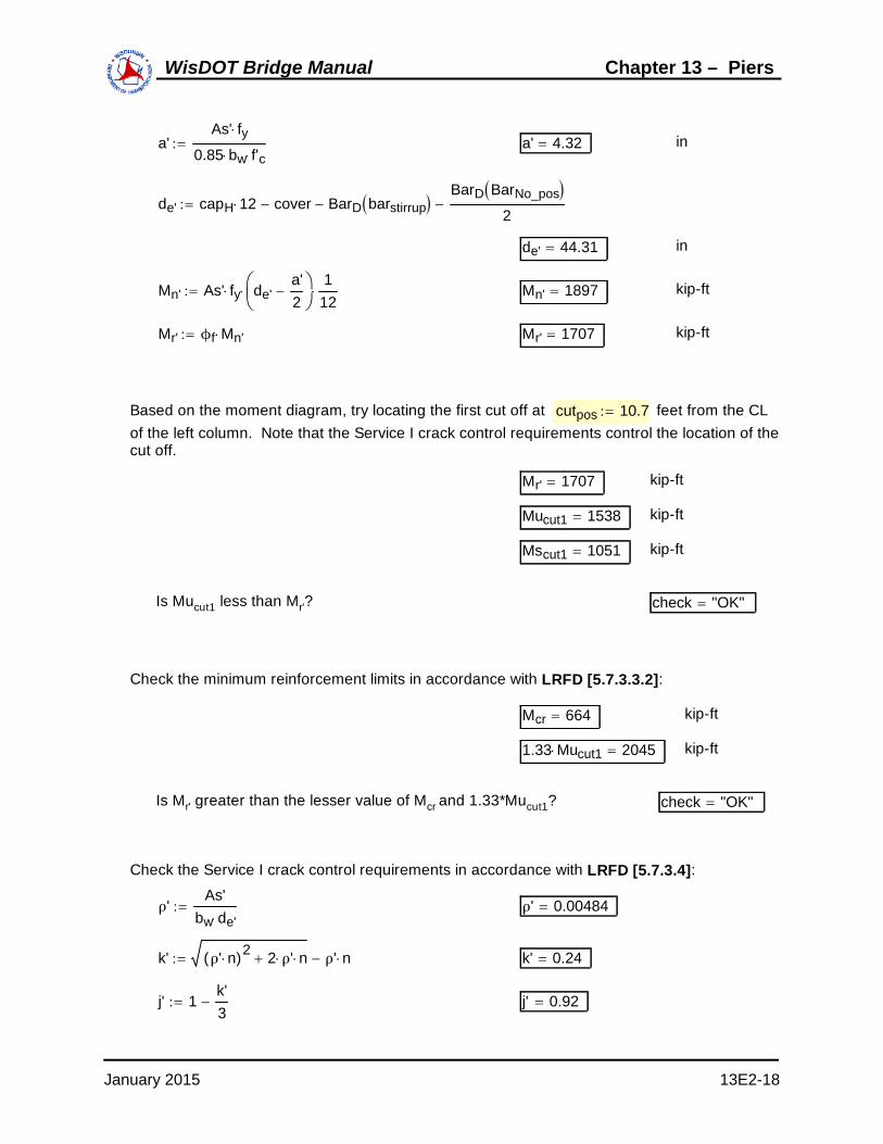
a'As' fy
0.85 bw f'c a' 4.32 in
de' capH 12 cover BarD barstirrup BarD BarNo_pos
2
de' 44.31 in
Mn' As' fy de'a'2
1
12 Mn' 1897 kip-ft
Mr' ϕf Mn' Mr' 1707 kip-ft
Based on the moment diagram, try locating the first cut off at cutpos 10.7 feet from the CLof the left column. Note that the Service I crack control requirements control the location of thecut off.
Mr' 1707 kip-ft
Mucut1 1538 kip-ft
Mscut1 1051 kip-ft
Is Mucut1 less than Mr'? check "OK"
Check the minimum reinforcement limits in accordance with LRFD [5.7.3.3.2]:
Mcr 664 kip-ft
1.33 Mucut1 2045 kip-ft
Is Mr' greater than the lesser value of Mcr and 1.33*Mucut1? check "OK"
Check the Service I crack control requirements in accordance with LRFD [5.7.3.4]:
ρ'As'
bw de' ρ' 0.00484
k' ρ' n( )2 2 ρ' n ρ' n k' 0.24
j' 1k'3
j' 0.92
January 2015 13E2-18
WisDOT Bridge Manual Chapter 13 – Piers

Mscut1 1051 kip-ft
fs'Mscut1
As' j' de'12 < 0.6 fy fs' 34.39 ksi < 0.6 fy O.K.
β 1.12
γe 1
Smax'700γe
β fs'2 dc Smax' 10.81 in
spa' 4.33 in
Is the bar spacing less than Smax'? check "OK"
The bars shall be extended past this cut off point for a distance not less than the following,LRFD [5.11.1.2.1]:
de' 44.31 in
15 BarD BarNo_pos 16.92 in
incolspa 12
2010.95
BarExtendpos 44.31 in
The bars also must be extended past the point required for flexure the development length ofthe bar. From Chapter 9, Table 9.9-1, the development length for an epoxy coated number 9 bar with spacing less than 6-inches, is:
ld_9 5.083 ft
cutposBarExtendpos
12 14.39
0.4 colspa ld_9 12.38
Similar calculations show that the second layer bottom mat bars can also be terminated at adistance of 2.0 feet from the CL of the left column. At least one quarter of the bars shall beextended past the centerline of the support for continuous spans. Therefore, run the bottomlayer bars to the end of the cap.
January 2015 13E2-19
WisDOT Bridge Manual Chapter 13 – Piers

E13-2.6.3 Negative Moment Capacity at Face of Column
It is assumed that there will be one layer of negative moment reinforcement. Therefore theeffective depth of the section at the pier is:
cover 2.5 in
barstirrup 5 (transverse bar size)
BarD barstirrup 0.63 in (transverse bar diameter)
BarNo_neg 8
BarD BarNo_neg 1.00 in (Assumed bar size)
de_neg capH 12 cover BarD barstirrup BarD BarNo_neg
2
de_neg 44.38 in
For flexure in non-prestressed concrete, ϕf 0.9 .The width of the cap:
bw 42 in
Muneg 1174 kip-ft
Ru_negMuneg 12
ϕf bw de_neg2
Ru_neg 0.1892 ksi
ρneg 0.85f'cfy
1 12 Ru_neg
0.85 f'c
ρneg 0.00326
As_neg ρneg bw de_neg As_neg 6.08 in2
This requires nbars_neg 9 bars. Check spacing requirements.
spanegbw 2 cover BarD barstirrup BarD BarNo_neg
nbars_neg 1
spaneg 4.34 in
clearspa_neg spaneg BarD BarNo_neg clearspa_neg 3.34 in
check "OK"
January 2015 13E2-20
WisDOT Bridge Manual Chapter 13 – Piers

Asprov_neg BarA BarNo_neg nbars_neg Asprov_neg 7.07 in2
anegAsprov_neg fy
0.85 bw f'c aneg 3.39 in
Mnneg Asprov_neg fy de_neganeg
2
1
12 kip-ft
Mnneg 1508
kip-ftMrneg ϕf Mnneg Mrneg 1358
kip-ftMuneg 1174
Is Mu less than Mr? check "OK"
Check the minimum reinforcement limits in accordance with LRFD [5.7.3.3.2]:
Mcr 664 kip-ft
1.33 Muneg 1561 kip-ft
Is Mr greater than the lesser value of Mcr and 1.33*Mu? check "OK"
Check the Service I crack control requirements in accordance with LRFD [5.7.3.4]:
ρnegAsprov_neg
bw de_neg ρneg 0.00379
n 8
kneg ρneg n 2 2 ρneg n ρneg n kneg 0.22
jneg 1kneg
3 jneg 0.93
dc_neg cover BarD barstirrup BarD BarNo_neg
2 dc_neg 3.63 in
Msneg 844 kip-ft
fs_negMsneg
Asprov_neg jneg de_neg12 < 0.6 fy fs_neg 34.8 ksi < 0.6 fy O.K.
h 48 inThe height of the section, h, is:
January 2015 13E2-21
WisDOT Bridge Manual Chapter 13 – Piers

βneg 1dc_neg
0.7 h dc_neg βneg 1.12
γe 1.0 for Class 1 exposure condition
Smax_neg700γe
βneg fs_neg2 dc_neg Smax_neg 10.76 in
spaneg 4.34 in
Is the bar spacing less than Smax? check "OK"
E13-2.6.4 Negative Moment Reinforcement Cut Off Location
Cut 4 bars where the remaining 5 bars satisfy the moment diagram.
nbars_neg' 5
spa'neg spaneg 2 spa'neg 8.69 in
As'neg BarA BarNo_neg nbars_neg' As'neg 3.93 in2
a'negAs'neg fy
0.85 bw f'c a'neg 1.89 in
de_neg 44.38 in
Mn'_neg As'neg fy de_nega'neg
2
1
12 Mn'_neg 853 kip-ft
Mr'_neg ϕf Mn'_neg Mr'_neg 768 kip-ft
Based on the moment diagram, try locating the cut off at cutneg 15.3 feet from the CL ofthe left column. Note that the Service I crack control requirements control the location of thecut off.
January 2015 13E2-22
WisDOT Bridge Manual Chapter 13 – Piers

Mr'_neg 768 kip-ft
Muneg_cut 577 kip-ft
Msneg_cut 381 kip-ft
Is Mucut1 less than Mr'? check "OK"
Check the minimum reinforcement limits in accordance with LRFD [5.7.3.3.2]:
Mcr 664 kip-ft
1.33 Muneg_cut 767 kip-ft
Is Mr' greater than the lesser value of Mcr and 1.33*Mucut1? check "OK"
Check the Service I crack control requirements in accordance with LRFD [5.7.3.4]:
ρ'negAs'neg
bw de_neg ρ'neg 0.00211
k'neg ρ'neg n 2 2 ρ'neg n ρ'neg n k'neg 0.17
j'neg 1k'neg
3 j'neg 0.94
Msneg_cut 381 kip-ft
fs'_negMsneg_cut
As'neg j'neg de_neg12 < 0.6 fy fs'_neg 27.79 ksi < 0.6 fy O.K.
βneg 1.12
γe 1
Smax'_neg700γe
βneg fs'_neg2 dc_neg Smax'_neg 15.30 in
spa'neg 8.69 in
Is the bar spacing less than Smax'? check "OK"
The bars shall be extended past this cut off point for a distance not less than the following,LRFD [5.11.1.2.3]:
January 2015 13E2-23
WisDOT Bridge Manual Chapter 13 – Piers

de_neg 44.38 in
12 BarD BarNo_neg 12 in
incolspa colw 12
1610.69
BarExtendneg 44.38 in
These bars also must be extended past the point required for flexure the development lengthof the bar. From Chapter 9, Table 9.9-1, the development length for an epoxy coated number 8 "top" bar with spacing greater than 6-inches, is:
ld_8 3.25 ft
The cut off location is determined by the following:
cutnegBarExtendneg
12 11.6 ft
colspacolw
2 ld_8 13 ft
Therefore, the cut off location is located at the following distance from the CL of the left column:
cutofflocation 11.6 ft
By inspection, the remaining top mat reinforcement is adequate over the exterior columns. Theinside face of the exterior column is located at:
colfacecolw
21
colspa colface 0.11 % along cap
Munegative colface 378.37 kip-ft
Msnegative colface 229.74 kip-ft
January 2015 13E2-24
WisDOT Bridge Manual Chapter 13 – Piers
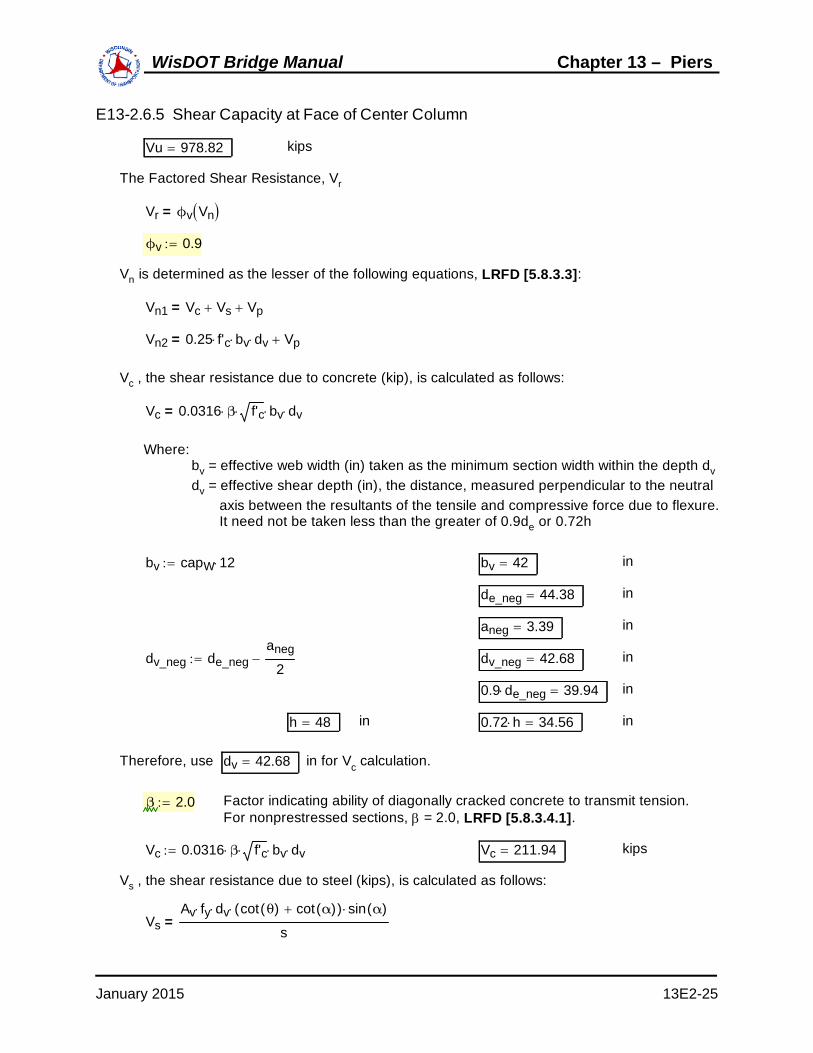
E13-2.6.5 Shear Capacity at Face of Center Column
Vu 978.82 kips
The Factored Shear Resistance, Vr
Vr ϕv Vn =
ϕv 0.9
Vn is determined as the lesser of the following equations, LRFD [5.8.3.3]:
Vn1 Vc Vs Vp=
Vn2 0.25 f'c bv dv Vp=
Vc , the shear resistance due to concrete (kip), is calculated as follows:
Vc 0.0316 β f'c bv dv=
Where: bv = effective web width (in) taken as the minimum section width within the depth dv dv = effective shear depth (in), the distance, measured perpendicular to the neutral axis between the resultants of the tensile and compressive force due to flexure. It need not be taken less than the greater of 0.9de or 0.72h
bv capW 12 bv 42 in
de_neg 44.38 in
aneg 3.39 in
dv_neg de_neganeg
2 dv_neg 42.68 in
0.9 de_neg 39.94 in
h 48 in 0.72 h 34.56 in
Therefore, use dv 42.68 in for Vc calculation.
β 2.0 Factor indicating ability of diagonally cracked concrete to transmit tension.For nonprestressed sections, = 2.0, LRFD [5.8.3.4.1].
Vc 0.0316 β f'c bv dv Vc 211.94 kips
Vs , the shear resistance due to steel (kips), is calculated as follows:
VsAv fy dv cot θ( ) cot α( )( ) sin α( )
s=
January 2015 13E2-25
WisDOT Bridge Manual Chapter 13 – Piers

Where:s = spacing of stirrups (in) = angle of inclination of diagonal compressive stresses (deg) = angle of inclination of transverse reinforcement to longitudinal axis (deg)
s 5 in
θ 45deg for non prestress members
α 90deg for vertical stirrups
Av = (# of stirrup legs)(area of stirrup)
barstirrup 5
StirrupConfig "Triple"
stirruplegs 6
Av stirruplegs BarA barstirrup Av 1.84 in2
VsAv fy dv cot θ( ) cot α( )( ) sin α( )
s Vs 942.74 kips
Vp , the component of the effective prestressing force in the direction of the applied shear:
Vp 0 for non prestressed members
Vn is the lesser of:
Vn1 Vc Vs Vp Vn1 1154.67 kips
Vn2 0.25 f'c bv dv Vp Vn2 1568.41 kips
Therefore, use: Vn 1154.67 kips
Vr ϕv Vn Vr 1039.2 kips
Vu 978.82 kips
check "OK"
January 2015 13E2-26
WisDOT Bridge Manual Chapter 13 – Piers

Check the Minimum Transverse Reinforcement, LRFD [5.8.2.5]
Required area of transverse steel:
Avmin 0.0316f'c bv s
fy Avmin 0.21 in2
Av 1.84 in2
Is the provided area of steel greater than Avmin? check "OK"
Check the Maximum Spacing of the Transverse Reinforcement, LRFD [5.8.2.7]
If vu<0.125f'c, then: smax 0.8 dv 24in
If vu > or = 0.125f'c, then: smax 0.4 dv 12in
The shear stress on the concrete, vu, is taken to be:
vuVu
ϕv bv dv vu 0.61 ksi
0.125 f'c 0.44 ksi
smax 12 in
s 5 in
Is the spacing provided less than the maximum spacing? check "OK"
Similar calculations are used to determine the required stirrup spacing for the remainder of thecap.
s2 12 in s3 6 in
StirrupConfig2 "Double" StirrupConfig3 "Double"
Vu2 276 kips Vu3 560 kips
Vr_2 408.94 Vr_3 627.13 kipskips
It should be noted that the required stirrup spacing is typically provided for a distance equal tothe cap depth past the CL of the girder. Consideration should also be given to minimize thenumber of stirrup spacing changes where practical. These procedures result in additionalcapacity in the pier cap that is often beneficial for potential future rehabilitation work on thestructure.
January 2015 13E2-27
WisDOT Bridge Manual Chapter 13 – Piers

E13-2.6.6 Temperature and Shrinkage SteelTemperature and shrinkage steel shall be provided on each face and in each direction ascalculated below. LRFD [5.10.8]
capW 3.5 ft
capH 4 ft
b capW 12 b 42 in
h 48 in
Asts1.30 b h
2 b h( ) fy Asts 0.24 in2/ft in each face
Is the area required between 0.11 and 0.60 in2 per foot? check "OK"
Use number 5 bars at one foot spacing: BarA 5( ) 0.31 in2/ft in each face
E13-2.6.7 Skin Reinforcement
If the effective depth, de, of the reinforced concrete member exceeds 3 ft., longitudinal skinreinforcement is uniformly distributed along both side faces of the component for a distance ofd/2 nearest the flexural tension reinforcement, LRFD [5.7.3.4]. The area of skin reinforcement(in2/ft of height) on each side of the face is required to satisfy:
Ask 0.012 de 30 As
4
Where:Ask = area of skin reinforcement (in2/ft)
As = area of tensile reinforcement (in2)de = flexural depth taken as the distance from the compression face to the centroid
of the steel, positive moment region (in)de 42.87 in
Ask1 0.012 de 30 Ask1 0.15 in2/ft
Ask2As
4 Ask2 3.32 in2/ft
Ask min Ask1 Ask2 Ask 0.15 in2/ft
spa_maxsk minde
612
spa_maxsk 7.15 in
Use number 5 bars at 6" spacing: BarA 5( ) 2 0.61 in2/ft in each face
January 2015 13E2-28
WisDOT Bridge Manual Chapter 13 – Piers
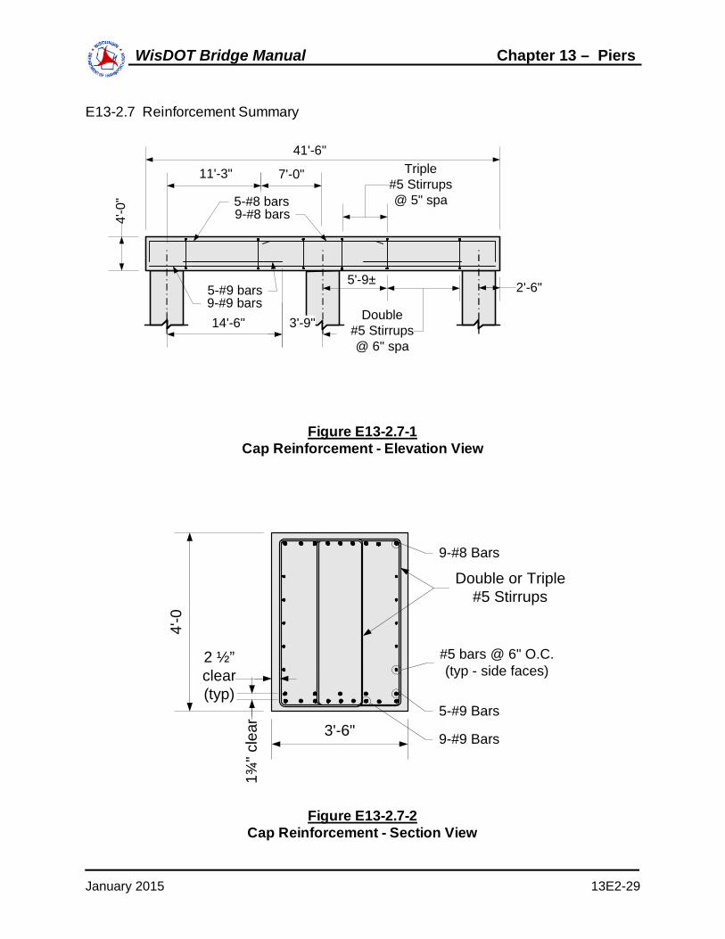
E13-2.7 Reinforcement Summary
2'-6"
41'-6"
4'-0
"
11'-3" 7'-0"
14'-6" 3'-9"
5-#8 bars9-#8 bars
9-#9 bars5-#9 bars
Triple#5 Stirrups@ 5" spa
Double#5 Stirrups@ 6" spa
5'-9±
Figure E13-2.7-1Cap Reinforcement - Elevation View
#5 bars @ 6" O.C. (typ - side faces)
4'-0
2 ½”clear (typ)
Double or Triple#5 Stirrups
9-#9 Bars
9-#8 Bars
1¾" c
lear 3'-6"
5-#9 Bars
Figure E13-2.7-2Cap Reinforcement - Section View
January 2015 13E2-29
WisDOT Bridge Manual Chapter 13 – Piers

WisDOT Bridge Manual
This page intentionally left blank.