wisdot bridge manual chapter 12 –...
TRANSCRIPT
WisDOT Bridge Manual Chapter 12 – Abutments
January 2015 12-1
Table of Contents
12.1 General ............................................................................................................................ 3
12.2 Abutment Types ............................................................................................................... 5
12.2.1 Full-Retaining ........................................................................................................... 5
12.2.2 Semi-Retaining ......................................................................................................... 6
12.2.3 Sill ............................................................................................................................ 7
12.2.4 Spill-Through or Open .............................................................................................. 7
12.2.5 Pile-Encased ............................................................................................................ 8
12.2.6 Special Designs ........................................................................................................ 8
12.3 Types of Abutment Support .............................................................................................. 9
12.3.1 Piles or Drilled Shafts ............................................................................................... 9
12.3.2 Spread Footings ..................................................................................................... 10
12.4 Abutment Wing Walls ..................................................................................................... 11
12.4.1 Wing Wall Length ................................................................................................... 11
12.4.1.1 Wings Parallel to Roadway ............................................................................. 11
12.4.1.2 Wings Not Parallel to Roadway and Equal Slopes .......................................... 12
12.4.2 Wing Wall Loads ..................................................................................................... 14
12.4.3 Wing Wall Parapets ................................................................................................ 15
12.5 Abutment Depths, Excavation and Construction............................................................. 16
12.5.1 Abutment Depths .................................................................................................... 16
12.5.2 Abutment Excavation .............................................................................................. 16
12.6 Abutment Drainage and Backfill ..................................................................................... 18
12.6.1 Abutment Drainage ................................................................................................. 18
12.6.2 Abutment Backfill Material ...................................................................................... 18
12.7 Selection of Standard Abutment Types .......................................................................... 21
12.8 Abutment Design Loads and Other Parameters ............................................................. 24
12.8.1 Application of Abutment Design Loads ................................................................... 24
12.8.2 Load Modifiers and Load Factors ........................................................................... 27
12.8.3 Live Load Surcharge............................................................................................... 28
12.8.4 Other Abutment Design Parameters ....................................................................... 29
12.8.5 Abutment and Wing Wall Design in Wisconsin........................................................ 30
12.8.6 Horizontal Pile Resistance ...................................................................................... 31
12.9 Abutment Body Details ................................................................................................... 32

WisDOT Bridge Manual Chapter 12 – Abutments
January 2015 12-2
12.9.1 Construction Joints ................................................................................................. 32
12.9.2 Beam Seats ............................................................................................................ 33
12.10 Timber Abutments ........................................................................................................ 35
12.11 Bridge Approach Design and Construction Practices ................................................... 36
WisDOT Bridge Manual Chapter 12 – Abutments
January 2015 12-3
12.1 General
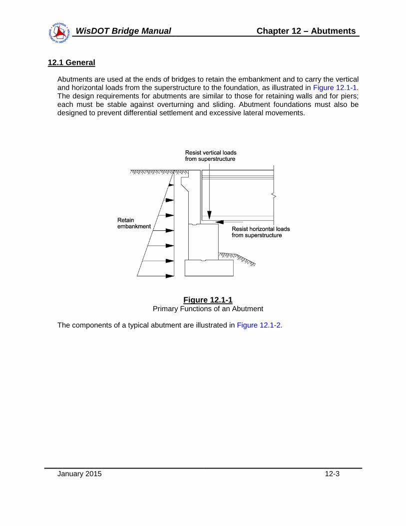
Abutments are used at the ends of bridges to retain the embankment and to carry the vertical and horizontal loads from the superstructure to the foundation, as illustrated in Figure 12.1-1. The design requirements for abutments are similar to those for retaining walls and for piers; each must be stable against overturning and sliding. Abutment foundations must also be designed to prevent differential settlement and excessive lateral movements.
Figure 12.1-1 Primary Functions of an Abutment
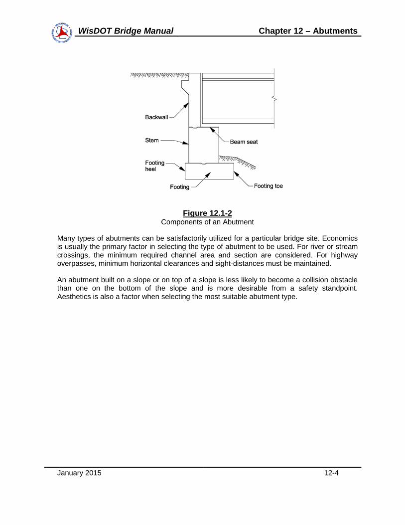
The components of a typical abutment are illustrated in Figure 12.1-2.
WisDOT Bridge Manual Chapter 12 – Abutments
January 2015 12-4
Figure 12.1-2 Components of an Abutment
Many types of abutments can be satisfactorily utilized for a particular bridge site. Economics is usually the primary factor in selecting the type of abutment to be used. For river or stream crossings, the minimum required channel area and section are considered. For highway overpasses, minimum horizontal clearances and sight-distances must be maintained.
An abutment built on a slope or on top of a slope is less likely to become a collision obstacle than one on the bottom of the slope and is more desirable from a safety standpoint. Aesthetics is also a factor when selecting the most suitable abutment type.
WisDOT Bridge Manual Chapter 12 – Abutments
January 2015 12-5
12.2 Abutment Types
Several different abutment types can be used, including full-retaining, semi-retaining, sill, spill-through or open, pile-encased and special designs. Each of these abutment types is described in the following sections.
12.2.1 Full-Retaining
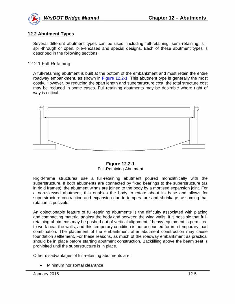
A full-retaining abutment is built at the bottom of the embankment and must retain the entire roadway embankment, as shown in Figure 12.2-1. This abutment type is generally the most costly. However, by reducing the span length and superstructure cost, the total structure cost may be reduced in some cases. Full-retaining abutments may be desirable where right of way is critical.
Figure 12.2-1 Full-Retaining Abutment
Rigid-frame structures use a full-retaining abutment poured monolithically with the superstructure. If both abutments are connected by fixed bearings to the superstructure (as in rigid frames), the abutment wings are joined to the body by a mortised expansion joint. For a non-skewed abutment, this enables the body to rotate about its base and allows for superstructure contraction and expansion due to temperature and shrinkage, assuming that rotation is possible.
An objectionable feature of full-retaining abutments is the difficulty associated with placing and compacting material against the body and between the wing walls. It is possible that full-retaining abutments may be pushed out of vertical alignment if heavy equipment is permitted to work near the walls, and this temporary condition is not accounted for in a temporary load combination. The placement of the embankment after abutment construction may cause foundation settlement. For these reasons, as much of the roadway embankment as practical should be in place before starting abutment construction. Backfilling above the beam seat is prohibited until the superstructure is in place.
Other disadvantages of full-retaining abutments are:
• Minimum horizontal clearance

WisDOT Bridge Manual Chapter 12 – Abutments
January 2015 12-6
• Minimum sight distance when roadway underneath is on a curved alignment
• Collision hazard when abutment front face is not protected
• Settlement
12.2.2 Semi-Retaining
The semi-retaining abutment (Types A3 and A4) is built somewhere between the bottom and top of the roadway embankment, as illustrated in Figure 12.2-2. It provides more horizontal clearance and sight distance than a full-retaining abutment. Located on the embankment slope, it becomes less of a collision hazard for a vehicle that is out of control.
Figure 12.2-2 Semi-Retaining Abutment
The description of full-retaining abutments in 12.2.1 generally applies to semi-retaining abutments as well. They are used primarily in highway-highway crossings as a substitute for a shoulder pier and sill abutment. Semi-retaining abutments generally are designed with a fixed base, allowing wing walls to be rigidly attached to the abutment body. The wings and the body of the abutment are usually poured monolithically.
For deep girder bridges (girder height > 60 inches) the aesthetic appearance of the A4 abutment is minimized and the A3 abutment should be considered.

WisDOT Bridge Manual Chapter 12 – Abutments
January 2015 12-7
12.2.3 Sill
The sill abutment (Type A1) is constructed at the top of the slope after the roadway embankment is close to final grade, as shown in Figure 12.2-3. The sill abutment helps avoid many of the problems that cause rough approach pavements. It eliminates the difficulties of obtaining adequate compaction adjacent to the relatively high walls of closed abutments. Since the approach embankment may settle by forcing up or bulging up the slope in front of the abutment body, a berm is often constructed at the front of the body. The weight of the berm helps prevent such bulging.
Figure 12.2-3 Sill Abutment
Sill abutments are the least expensive abutment type and are usually the easiest to construct. However, this abutment type results in a higher superstructure cost, so the overall cost of the structure should be evaluated with other alternatives.
For shallow superstructures where wing piles are not required, the Type A1 abutment is used with a fixed seat. This minimizes cracking between the body wall and wings. However, for shallow superstructures where wing piles are required, the Type A1 abutment is used with a semi-expansion seat. This allows superstructure movement, and it reduces potential cracking between the wings and body.
The parallel-to-abutment-centerline wings or elephant-ear wings, as shown on the Standard Details for Wings Parallel to A1 Abutment Centerline, should be used for grade separations when possible. This wing type is preferred because it increases flexibility in the abutment, it simplifies compaction of fill, and it improves stability. Wings parallel to the roadway are still required at stream crossings where high water may be a problem.
12.2.4 Spill-Through or Open
A spill-through or open abutment is mostly used where an additional span may be added to the bridge in the future. It may also be used to satisfy unique construction problems. This abutment type is situated on columns or stems that extend upward from the natural ground. It is essentially a pier being used as an abutment.
It is very difficult to properly compact the embankment materials that must be placed around the columns and under the abutment cap. Early settlement and erosion are problems frequently encountered with spill-through or open abutments.

WisDOT Bridge Manual Chapter 12 – Abutments
January 2015 12-8
If the abutment is to be used as a future pier, it is important that the wings and backwall be designed and detailed for easy removal. Construction joints should be separated by felt or other acceptable material. Reinforcing steel should not extend through the joints. Bolts with threaded inserts should be used to carry tension stresses across joints.
12.2.5 Pile-Encased
Pile-encased abutments (Type A5) should only be used where documented cost data shows them to be more economical than sill abutments due to site conditions. For local roads right-of-way acquisition can be difficult, making the A5 a good option. Requiring crane access from only one side of a stream may be another reason to use a single span bridge with A5 abutments, as would savings in railing costs. Steeper topography may make A5 abutments a more reasonable choice than sill abutments. In general, however, using sill abutments with longer bridges under most conditions has cost advantages over using the Type A5 abutments. Type A5 abutments may require additional erosion control measures that increase construction cost.
The wall height of pile-encased abutments is limited to a maximum of 10 feet since increased wall height will increase soil pressure, resulting in uneconomical pile design due to size or spacing requirements. Reinforcement in the abutment body is designed based on live load surcharge and soil pressure on the back wall.
Pile-encased abutments are limited to a maximum skew of 15 and 30 degrees with girder structures and slab structures, respectively, in order to limit damage due to thermal expansion and contraction of the superstructure. Wing skew angles are at 45 degrees relative to the body to prevent cracking between the abutment body and wings.
12.2.6 Special Designs
In addition to the standard abutment types described in the previous sections, many different styles and variations of those abutment types can also be designed. Such special abutment designs may be required due to special aesthetic requirements, unique soil conditions or unique structural reasons. Special designs of abutments require prior approval by the Bureau of Structures Development Chief.
WisDOT Bridge Manual Chapter 12 – Abutments
January 2015 12-9
12.3 Types of Abutment Support
Piles, drilled shafts and spread footings are the general types of abutment support used. This section provides a brief description of each type of abutment support.
WisDOT policy item:
Geotechnical design of abutment supports shall be in accordance with the 4th Edition of the AASHTO LRFD Bridge Design Specifications for Highway Bridges. No additional guidance is available at this time.
Structural design of abutment supports shall be in accordance with LRFD, as specified in the 4th Edition of AASHTO LRFD Bridge Design Specifications
12.3.1 Piles or Drilled Shafts
Most abutments are supported on piles to prevent abutment settlement. Bridge approach embankments are usually constructed of fill material that can experience settlement over several years. This settlement may be the result of the type of embankment material or the original foundation material under the embankment. By driving piles through the embankment and into the original ground, abutments usually do not settle with the embankment. A settling embankment may be resisted by the abutment piles through friction between the piles and fill material. The added load to friction piles and the need for preboring should be considered.
It is generally not necessary to prebore non-displacement piles for any fill depths, and it is not necessary to prebore displacement piles for fill depths less than 15 feet below the bottom of footing. However, for some problem soils this may not apply. See the soils report to determine if preboring is required. If required, the Special Provisions must be written with preboring guidelines.
Battered piles may cause more of a problem than vertical piles and are given special consideration. When driving battered piles, reduced hammer efficiency may be experienced, and battered piles should not be considered when negative skin friction loads are anticipated.
Fill embankments frequently shift laterally, as well as vertically. A complete foundation site investigation and information on fill material is a prerequisite for successful pile design.
Piles placed in prebored holes cored into rock do not require driving. The full design loading can be used if the hole is of adequate size to prevent pile hangups and to allow filling with concrete.
Piles in abutments are subject to lateral loads. The lateral resistance on a pile is usually determined from an acceptable level of lateral displacement and not the ultimate load that causes a stress failure in the pile. The lateral resistance on a pile may be more dependent on the material into which the pile is driven than on the pile type. See Chapter 11 – Foundation Support for a more thorough discussion of piles and allowable pile loads.

WisDOT Bridge Manual Chapter 12 – Abutments
January 2015 12-10
12.3.2 Spread Footings
Abutments on spread footings are generally used only in cut sections where the original soil can sustain reasonable pressures without excessive settlement. The bearing resistance is determined by the Geotechnical Section or the geotechnical consultant.
With improved procedures and better control of embankment construction, spread footings can be used successfully on fill material. It is important that construction be timed to permit the foundation material to consolidate before the spread footings are constructed. An advantage of spread footings is that the differential settlement between approach fills and abutments is minimized.
The use of spread footings is given greater consideration for simple-span bridges than for continuous-span bridges. However, under special conditions, continuous-span bridges can be designed for small amounts of settlement. Drainage for abutments on spread footings can be very critical. For these reasons, pile footings are usually preferred.
Lateral forces on abutments are resisted by passive earth pressure and friction between the soil and concrete. A shear key provides additional area on which passive earth pressure can act. A berm in front of the abutment may be necessary to prevent a shear failure in the soil along the slope.
WisDOT Bridge Manual Chapter 12 – Abutments
January 2015 12-11
12.4 Abutment Wing Walls
This section provides general equations used to compute wing wall lengths, as well as a brief description of wing wall loads and parapets.
12.4.1 Wing Wall Length
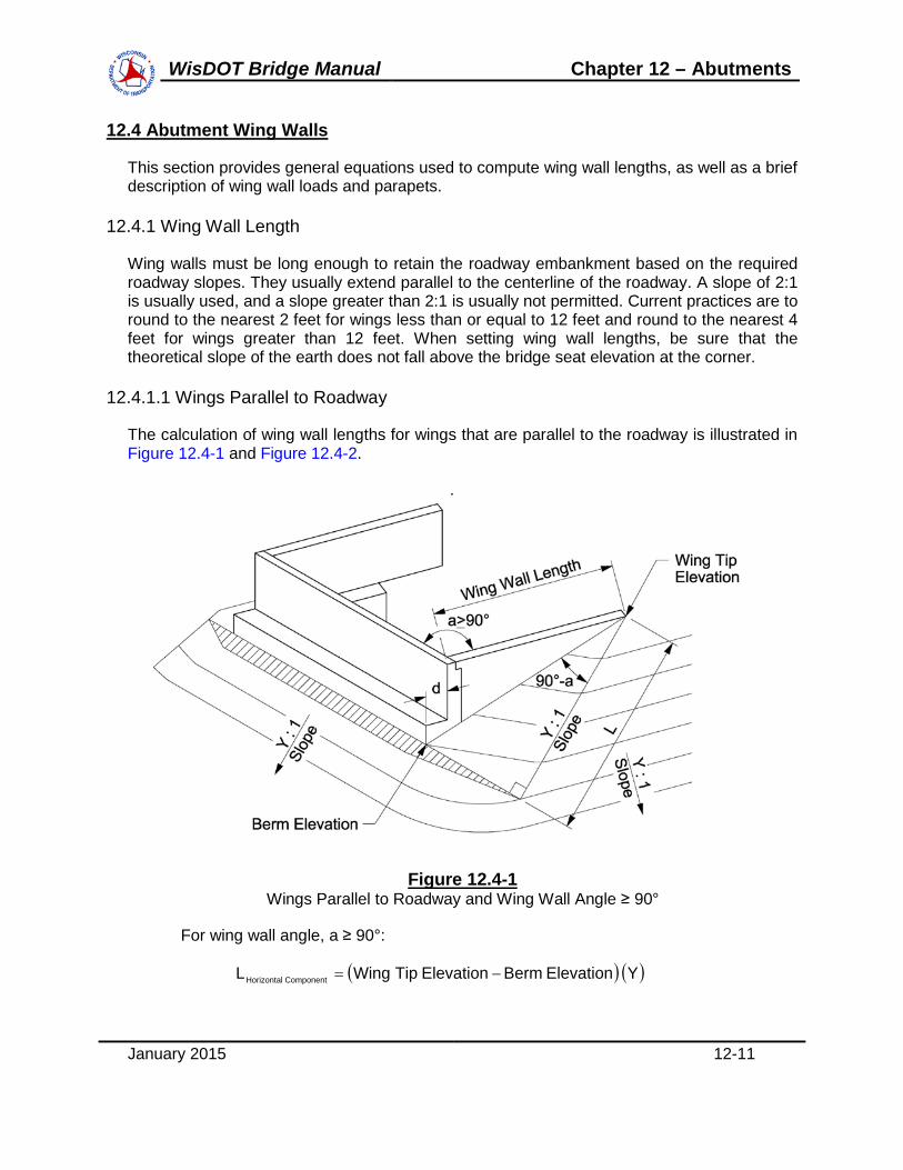
Wing walls must be long enough to retain the roadway embankment based on the required roadway slopes. They usually extend parallel to the centerline of the roadway. A slope of 2:1 is usually used, and a slope greater than 2:1 is usually not permitted. Current practices are to round to the nearest 2 feet for wings less than or equal to 12 feet and round to the nearest 4 feet for wings greater than 12 feet. When setting wing wall lengths, be sure that the theoretical slope of the earth does not fall above the bridge seat elevation at the corner.
12.4.1.1 Wings Parallel to Roadway
The calculation of wing wall lengths for wings that are parallel to the roadway is illustrated in Figure 12.4-1 and Figure 12.4-2.
.
Figure 12.4-1 Wings Parallel to Roadway and Wing Wall Angle ≥ 90°
For wing wall angle, a ≥ 90°:
( ) ( )YElevationBermElevationTipWingL ComponentHorizontal −=
WisDOT Bridge Manual Chapter 12 – Abutments
January 2015 12-12
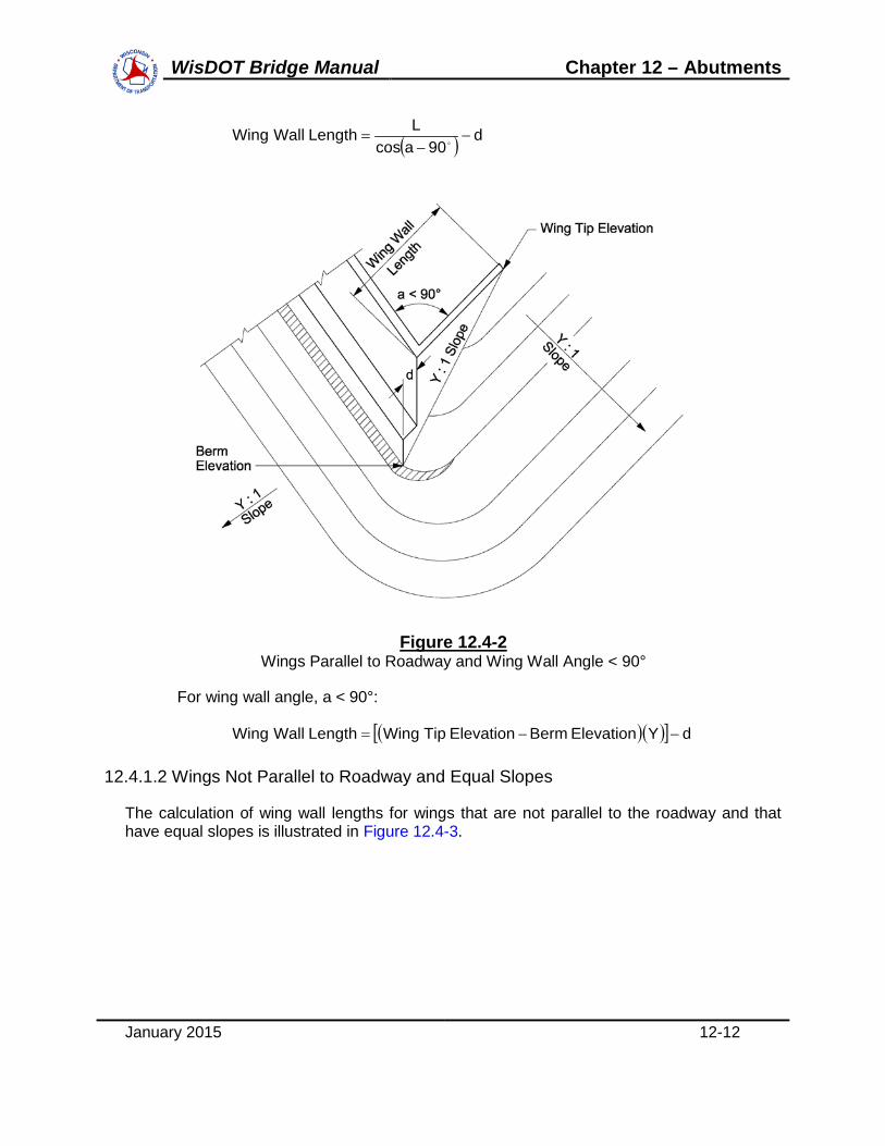
( ) d90acos
LLengthWallWing −−
=
Figure 12.4-2 Wings Parallel to Roadway and Wing Wall Angle < 90°
For wing wall angle, a < 90°:
( )( )[ ] dYElevationBermElevationTipWingLengthWallWing −−=
12.4.1.2 Wings Not Parallel to Roadway and Equal Slopes
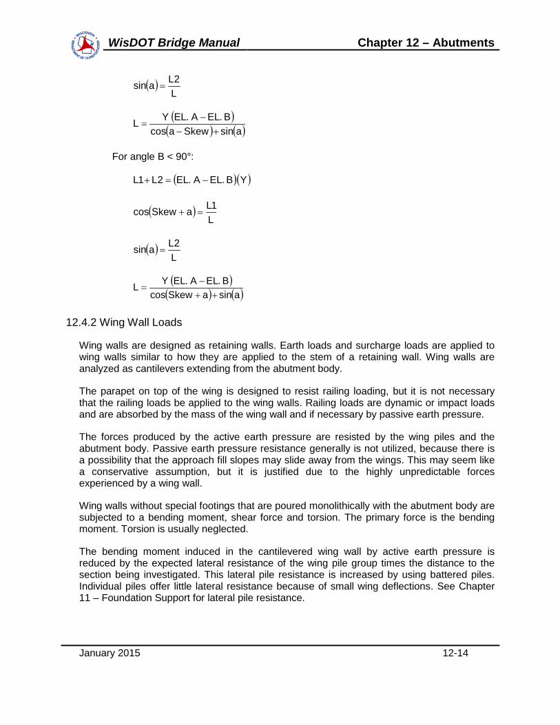
The calculation of wing wall lengths for wings that are not parallel to the roadway and that have equal slopes is illustrated in Figure 12.4-3.

WisDOT Bridge Manual Chapter 12 – Abutments
January 2015 12-13
Figure 12.4-3 Wings Not Parallel to Roadway and Equal Slopes
For angle B ≥ 90°:
( )( )YB.ELA.EL2L1L −=+
( )L1LSkewacos =−
WisDOT Bridge Manual Chapter 12 – Abutments
January 2015 12-14
( )L2Lasin =
( )( ) ( )asinSkewacos
B.ELA.ELYL+−
−=
For angle B < 90°:
( )( )YB.ELA.EL2L1L −=+
( )L1LaSkewcos =+
( )L2Lasin =
( )( ) ( )asinaSkewcos
B.ELA.ELYL++
−=
12.4.2 Wing Wall Loads
Wing walls are designed as retaining walls. Earth loads and surcharge loads are applied to wing walls similar to how they are applied to the stem of a retaining wall. Wing walls are analyzed as cantilevers extending from the abutment body.
The parapet on top of the wing is designed to resist railing loading, but it is not necessary that the railing loads be applied to the wing walls. Railing loads are dynamic or impact loads and are absorbed by the mass of the wing wall and if necessary by passive earth pressure.
The forces produced by the active earth pressure are resisted by the wing piles and the abutment body. Passive earth pressure resistance generally is not utilized, because there is a possibility that the approach fill slopes may slide away from the wings. This may seem like a conservative assumption, but it is justified due to the highly unpredictable forces experienced by a wing wall.
Wing walls without special footings that are poured monolithically with the abutment body are subjected to a bending moment, shear force and torsion. The primary force is the bending moment. Torsion is usually neglected.
The bending moment induced in the cantilevered wing wall by active earth pressure is reduced by the expected lateral resistance of the wing pile group times the distance to the section being investigated. This lateral pile resistance is increased by using battered piles. Individual piles offer little lateral resistance because of small wing deflections. See Chapter 11 – Foundation Support for lateral pile resistance.

WisDOT Bridge Manual Chapter 12 – Abutments
January 2015 12-15
12.4.3 Wing Wall Parapets
Steel plate beam guard is used at bridge approaches and is attached to the wing wall parapets. This helps to prevent vehicles from colliding directly into the end of the parapet.
A vehicle striking a guard rail may produce a high-tension force in the guard rail. It is important that sufficient longitudinal parapet steel be provided to resist this force. If the concrete in the parapet is demolished, the longitudinal steel continues to act as a cable guard rail if it remains attached to the steel plate beam guard.

WisDOT Bridge Manual Chapter 12 – Abutments
January 2015 12-16
12.5 Abutment Depths, Excavation and Construction
This section describes some additional design considerations for abutments, including depth, excavation and construction.
Abutment construction must satisfy the requirements for construction joints and beam seats presented in 12.9.1 and 12.9.2, respectively.
The abutment body is generally located above the normal water. Refer to the Standard Specifications or Special Provisions if part of the abutment body is below normal water.
12.5.1 Abutment Depths
The required depth of the abutment footing to prevent frost damage depends on the amount of water in the foundation material. Frost damage works in two directions. First, ice lenses form in the soil, heaving it upward. These lenses grow by absorbing additional water from below the frost line. Silts are susceptible to heaves, but well-drained sands and dense clays generally do not heave. Second, the direction of frost action is downward. The ice lenses thaw from the top down, causing a layer of water to be trapped near the surface. This water emulsifies the soil, permitting it to flow out from under the footing.
Sill and semi-retaining abutments are constructed on slopes which remain relatively moisture free. Sill abutments have been constructed in all parts of Wisconsin with footings only 2.5 feet below ground and have experienced no frost heave problems.
Full-retaining abutments are constructed at the bottom of embankment slopes, and their footings are more likely to be within a soil of high moisture content. Therefore, footings for full-retaining abutments must be located below the level of maximum frost penetration. Maximum frost penetration varies from 4 feet in the southeastern part of Wisconsin to 6 feet in the northwestern corner.
12.5.2 Abutment Excavation
Abutment excavation is referred to as "Excavation for Structures Bridges." It is measured as a unit for each specific bridge and is paid for at the contract lump sum price.
When a new bridge is constructed, a new roadway approaching the bridge is generally also constructed. Since the roadway contractor and bridge contractor are not necessarily the same, the limits of excavation to be performed by each must be specified. The roadway contractor cuts or fills earth to the upper limits of structural excavation as specified on the bridge plans or in the Standard Specifications for Highway and Structure Construction. If the bridge contractor does his work before the roadway contractor or if there is no roadway contract, the upper limit of structural excavation is the existing ground line. For sill abutments, the upper limit is specified in the Standard Specifications and need not be shown on the abutment plans.
For semi-retaining and full-retaining abutments, the upper limits are shown on the abutment plans. If a cut condition exists, the upper limit is usually the subgrade elevation and the top surface of the embankment slope (bottom of slope protection). Earth above these limits is

WisDOT Bridge Manual Chapter 12 – Abutments
January 2015 12-17
removed by the roadway contractor. A semi-retaining or full-retaining abutment placed on fill is considered a unique problem by the design engineer, and limits of excavation must be set accordingly. Construction sequence and type of fill material are considered when setting excavation limits. Slopes greater than 1.5 horizontal to 1 vertical are difficult to construct and generally are not specified. It is sometimes advantageous to have the roadway contractor place extra fill that later must be excavated by the bridge contractor, because the overburden aids in compaction and reduces subsequent settlement.
Lateral limits of excavation are not defined in the Standard Specifications. The contractor must excavate whatever is necessary within the right-of-way for the placement of the forms.

WisDOT Bridge Manual Chapter 12 – Abutments
January 2015 12-18
12.6 Abutment Drainage and Backfill
This section describes abutment design considerations related to drainage and backfill. The abutment drainage and backfill must be designed and detailed properly to prevent undesirable loads from being applied to the abutment.
12.6.1 Abutment Drainage
Abutment drainage is necessary to prevent hydrostatic pressure and frost pressure. Hydrostatic pressure, including both soil and water, can amount to an equivalent fluid unit weight of soil of 85 pcf. Frost action, which can occur in silty backfill, may result in extremely high pressures. On high abutments, these pressures will produce a very large force which could result in structural damage or abutment movement if not accounted for in the design.
To prevent these additional pressures on abutments, it is necessary to drain away whatever water accumulates behind the body and wings. This is accomplished using a pervious granular fill on the inside face of the abutment. Pipe underdrain must be provided to drain the fill located behind the abutment body and wings. For rehabilitation of structures, provide plan details to replace inadequate underdrain systems.
Past experience indicates that sill abutments are not capable of withstanding hydrostatic pressure on their full height without leaking.
Semi-retaining and full-retaining abutments generally will be overstressed or may slide if subject to large hydrostatic or frost pressures unless accounted for in the design. Therefore, “Pipe Underdrain Wrapped 6-inch” is required behind all abutments. This pipe underdrain is used behind the abutment and outside the abutment to drain the water away. It is best to place the pipe underdrain at the bottom of footing elevation as per standards. However, if it is not possible to discharge the water to a lower elevation, the pipe underdrain should be placed higher.
Pipe underdrains and weepholes may discharge water during freezing temperatures. In urban areas, this may create a problem due to the accumulation of flow and ice on sidewalks.
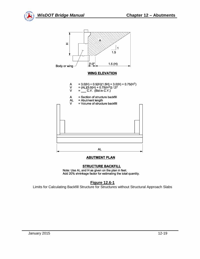
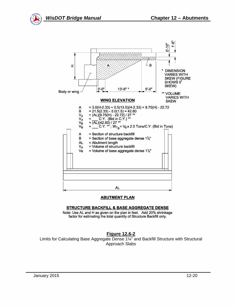
12.6.2 Abutment Backfill Material
All abutments and wings shall utilize “Backfill Structure” to facilitate drainage. The limits for calculating the material quantity are as shown in Figure 12.6-1 for structures that do not utilize structural approach slabs. For structures that do utilize structural approach slabs, Figure 12.6-2 shows the limits for calculating the material quantities for “Base Aggregate Dense 1¼”. These sketches should not be included on the contract plans.
WisDOT Bridge Manual Chapter 12 – Abutments
January 2015 12-19
Figure 12.6-1 Limits for Calculating Backfill Structure for Structures without Structural Approach Slabs
WisDOT Bridge Manual Chapter 12 – Abutments
January 2015 12-20
Figure 12.6-2 Limits for Calculating Base Aggregate Dense 1¼” and Backfill Structure with Structural
Approach Slabs

WisDOT Bridge Manual Chapter 12 – Abutments
January 2015 12-21
12.7 Selection of Standard Abutment Types
From past experience and investigations, the abutment types presented in Figure 12.7-1 are generally most suitable and economical for the given conditions. Although piles are shown for each abutment type, drilled shafts or spread footings may also be utilized depending on the material conditions at the bridge site. The chart in Figure 12.7-1 provides a recommended guide for abutment type selection.

WisDOT Bridge Manual Chapter 12 – Abutments
January 2015 12-22
Figure 12.7-1 Recommended Guide for Abutment Type Selection
WisDOT Bridge Manual Chapter 12 – Abutments
January 2015 12-23
Footnotes to Figure 12.7-1:
a. Type A1 fixed abutments are not used when wing piles are required. The semi-expansion seat is used to accommodate superstructure movements and to minimize cracking between the wings and body wall. See Standards for Abutment Type A1 (Integral Abutment) and Abutment Type A1 for additional guidance.
b. Consider the flexibility of the piers when choosing this abutment type. Only one expansion bearing is needed if the structure is capable of expanding easily in one direction. With rigid piers, symmetry is important in order to experience equal expansion movements and to minimize the forces on the substructure units.
c. For two-span prestressed girder bridges, the sill abutment is more economical than a semi-retaining abutment if the maximum girder length is not exceeded. It also is usually more economical if the next girder size is required.
d. For two-span steel structures with long spans, the semi-retaining abutments may be more economical than sill abutments due to the shorter bridge lengths if a deeper girder is required.

WisDOT Bridge Manual Chapter 12 – Abutments
January 2015 12-24
12.8 Abutment Design Loads and Other Parameters
This section provides a brief description of the application of abutment design loads, a summary of load modifiers, load factors and other design parameters used for abutment and wing wall design, and a summary of WisDOT abutment design policy items.
12.8.1 Application of Abutment Design Loads
An abutment is subjected to both horizontal and vertical loads from the superstructure. The number and spacing of the superstructure girders determine the number and location of the concentrated reactions that are resisted by the abutment. The abutment also resists loads from the backfill material and any water that may be present.
Although the vertical and horizontal reactions from the superstructure represent concentrated loads, they are commonly assumed to be distributed over the entire length of the abutment wall or stem that support the reactions. That is, the sum of the reactions, either horizontal or vertical, is divided by the length of the wall to obtain a load per unit length to be used in both the stability analysis and the structural design. This procedure is sufficient for most design purposes.
Approach loads are not considered in the example below. However, designers shall include vertical reactions from reinforced concrete approaches as they directly transmit load from the approaches to the abutment. Reinforced concrete approaches include the concrete approach slab system (refer to FDM 14-10-15) and the structural approach slab system (as described in this chapter).
The first step in computing abutment design loads is to compute the dead load reactions for each girder or beam. To illustrate this, consider a 60-foot simple span structure with a roadway width of 44 feet, consisting of steel beams spaced at 9 feet and carrying an HL-93 live loading.
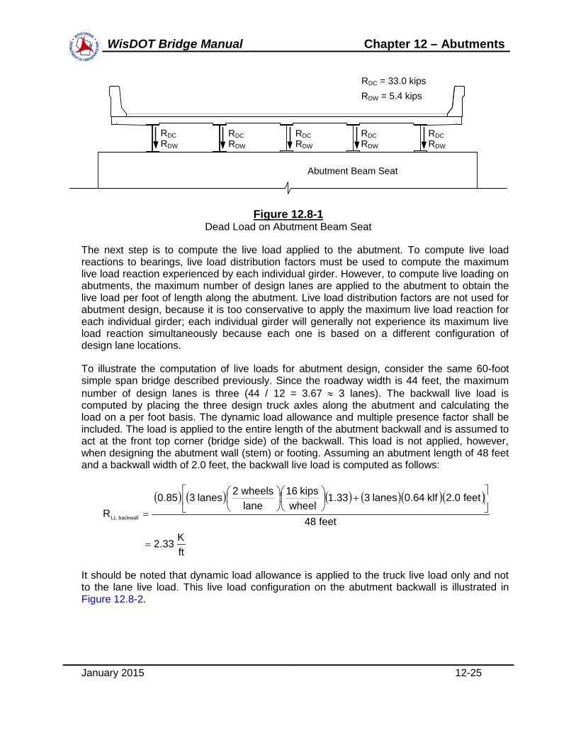
The dead load forces, DC and DW, acting on the abutments shall include reactions from the superstructure. DC dead loads include structural components and nonstructural attachments, and DW dead loads include wearing surfaces and utilities. If the total DC dead load is 1.10 kips per foot of girder and the total DW dead load is 0.18 kips per foot of girder, then the dead load reaction per girder is computed as follows:
( ) kips0.332Feet60ft/K10.1RDC =
=
( ) kips4.52Feet60ft/K18.0RDW =
=
These dead loads are illustrated in Figure 12.8-1. The dead loads are equally distributed over the full length of the abutment.
WisDOT Bridge Manual Chapter 12 – Abutments
January 2015 12-25
Abutment Beam Seat
RDW = 5.4 kipsRDC = 33.0 kips
RDCRDW
RDCRDW
RDCRDW
RDCRDW
RDCRDW
Figure 12.8-1 Dead Load on Abutment Beam Seat
The next step is to compute the live load applied to the abutment. To compute live load reactions to bearings, live load distribution factors must be used to compute the maximum live load reaction experienced by each individual girder. However, to compute live loading on abutments, the maximum number of design lanes are applied to the abutment to obtain the live load per foot of length along the abutment. Live load distribution factors are not used for abutment design, because it is too conservative to apply the maximum live load reaction for each individual girder; each individual girder will generally not experience its maximum live load reaction simultaneously because each one is based on a different configuration of design lane locations.
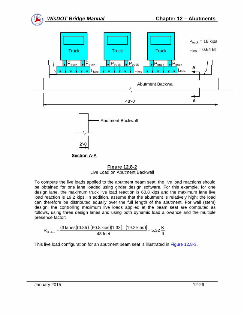
To illustrate the computation of live loads for abutment design, consider the same 60-foot simple span bridge described previously. Since the roadway width is 44 feet, the maximum number of design lanes is three (44 / 12 = 3.67 ≈ 3 lanes). The backwall live load is computed by placing the three design truck axles along the abutment and calculating the load on a per foot basis. The dynamic load allowance and multiple presence factor shall be included. The load is applied to the entire length of the abutment backwall and is assumed to act at the front top corner (bridge side) of the backwall. This load is not applied, however, when designing the abutment wall (stem) or footing. Assuming an abutment length of 48 feet and a backwall width of 2.0 feet, the backwall live load is computed as follows:
( ) ( ) ( ) ( )( )( )
ftK33.2
feet48
feet0.2klf64.0lanes333.1wheel
kips16lanewheels2lanes385.0
R backwallLL
=
+
=
It should be noted that dynamic load allowance is applied to the truck live load only and not to the lane live load. This live load configuration on the abutment backwall is illustrated in Figure 12.8-2.
WisDOT Bridge Manual Chapter 12 – Abutments
January 2015 12-26
Figure 12.8-2 Live Load on Abutment Backwall
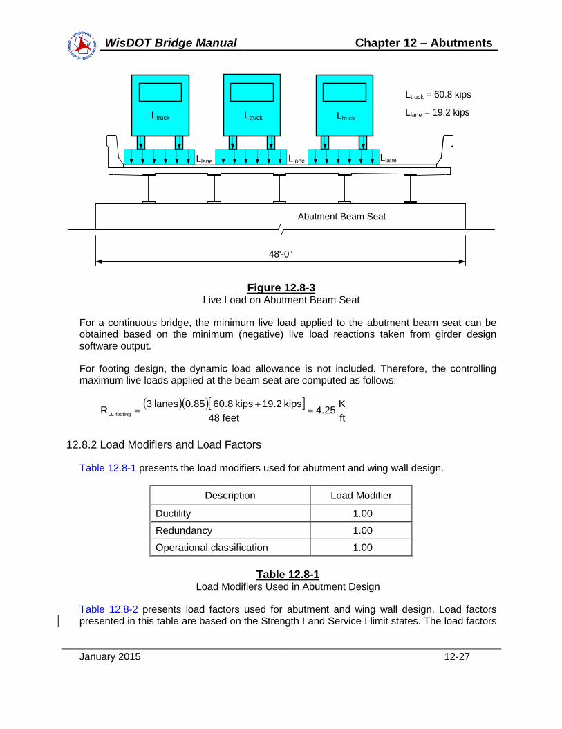
To compute the live loads applied to the abutment beam seat, the live load reactions should be obtained for one lane loaded using girder design software. For this example, for one design lane, the maximum truck live load reaction is 60.8 kips and the maximum lane live load reaction is 19.2 kips. In addition, assume that the abutment is relatively high; the load can therefore be distributed equally over the full length of the abutment. For wall (stem) design, the controlling maximum live loads applied at the beam seat are computed as follows, using three design lanes and using both dynamic load allowance and the multiple presence factor:
( )( ) ( )( ) ( )[ ]ftK32.5
feet48kips2.1933.1kips8.6085.0lanes3R stemLL =
+=
This live load configuration for an abutment beam seat is illustrated in Figure 12.8-3.
Truck
Llane
Truck
Llane
Truck
Llane
Abutment Backwall
Llane = 0.64 klf
Ptruck Ptruck Ptruck Ptruck Ptruck Ptruck
Ptruck = 16 kips
48'-0" A
Abutment Backwall
2'-0"
Section A-A
A
WisDOT Bridge Manual Chapter 12 – Abutments
January 2015 12-27
Ltruck
Llane Llane Llane
Abutment Beam Seat
Llane = 19.2 kips
Ltruck = 60.8 kips
48'-0"
Ltruck Ltruck
Figure 12.8-3 Live Load on Abutment Beam Seat
For a continuous bridge, the minimum live load applied to the abutment beam seat can be obtained based on the minimum (negative) live load reactions taken from girder design software output.
For footing design, the dynamic load allowance is not included. Therefore, the controlling maximum live loads applied at the beam seat are computed as follows:
( )( )[ ]ftK25.4
feet48kips2.19kips8.6085.0lanes3R footingLL =
+=
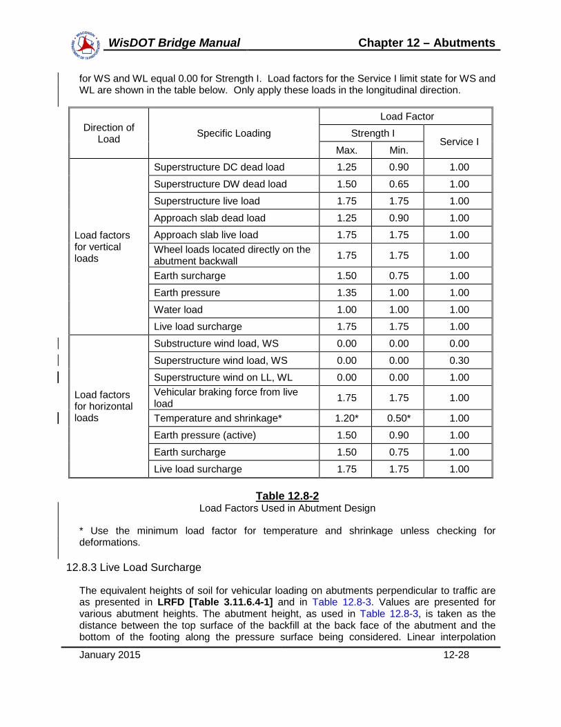
12.8.2 Load Modifiers and Load Factors
Table 12.8-1 presents the load modifiers used for abutment and wing wall design.
Description Load Modifier
Ductility 1.00
Redundancy 1.00
Operational classification 1.00
Table 12.8-1 Load Modifiers Used in Abutment Design
Table 12.8-2 presents load factors used for abutment and wing wall design. Load factors presented in this table are based on the Strength I and Service I limit states. The load factors
WisDOT Bridge Manual Chapter 12 – Abutments
January 2015 12-28
for WS and WL equal 0.00 for Strength I. Load factors for the Service I limit state for WS and WL are shown in the table below. Only apply these loads in the longitudinal direction.
Direction of Load Specific Loading
Load Factor Strength I
Service I Max. Min.
Load factors for vertical loads
Superstructure DC dead load 1.25 0.90 1.00
Superstructure DW dead load 1.50 0.65 1.00
Superstructure live load 1.75 1.75 1.00
Approach slab dead load 1.25 0.90 1.00 Approach slab live load 1.75 1.75 1.00 Wheel loads located directly on the abutment backwall 1.75 1.75 1.00
Earth surcharge 1.50 0.75 1.00
Earth pressure 1.35 1.00 1.00
Water load 1.00 1.00 1.00 Live load surcharge 1.75 1.75 1.00
Load factors for horizontal loads
Substructure wind load, WS 0.00 0.00 0.00
Superstructure wind load, WS 0.00 0.00 0.30
Superstructure wind on LL, WL 0.00 0.00 1.00 Vehicular braking force from live load 1.75 1.75 1.00
Temperature and shrinkage* 1.20* 0.50* 1.00
Earth pressure (active) 1.50 0.90 1.00
Earth surcharge 1.50 0.75 1.00
Live load surcharge 1.75 1.75 1.00
Table 12.8-2 Load Factors Used in Abutment Design
* Use the minimum load factor for temperature and shrinkage unless checking for deformations.
12.8.3 Live Load Surcharge
The equivalent heights of soil for vehicular loading on abutments perpendicular to traffic are as presented in LRFD [Table 3.11.6.4-1] and in Table 12.8-3. Values are presented for various abutment heights. The abutment height, as used in Table 12.8-3, is taken as the distance between the top surface of the backfill at the back face of the abutment and the bottom of the footing along the pressure surface being considered. Linear interpolation

WisDOT Bridge Manual Chapter 12 – Abutments
January 2015 12-29
should be used for intermediate abutment heights. The load factors for both vertical and horizontal components of live load surcharge are as specified in LRFD [Table 3.4.1-1] and in Table 12.8-2.
Abutment Height (Feet) heq (Feet)
5.0 4.0 10.0 3.0
≥ 20.0 2.0
Table 12.8-3 Equivalent Height, heq, of Soil for Vehicular Loading on Abutments Perpendicular to Traffic
WisDOT policy item:
The equivalent height of soil for vehicular loading on retaining walls parallel to traffic shall be 2.0 feet, regardless of the wall height. For standard unit weight of soil equal to 120 pcf, the resulting live load surcharge is 240 psf.
For abutments without reinforced concrete approaches, the equivalent height of soil for vehicular loading on abutments shall be based on Table 12.8-3. For abutments with reinforced concrete approaches, one half of the equivalent height of soil shall be used to calculate the horizontal load on the abutment.
12.8.4 Other Abutment Design Parameters
The equivalent fluid unit weights of soils are as presented in LRFD [Table 3.11.5.5-1]. Values are presented for loose sand or gravel, medium dense sand or gravel, and dense sand or gravel. Values are also presented for level or sloped backfill and for at-rest or active soil conditions.
Table 12.8-4 presents other parameters used in the design of abutments and wing walls. Standard details are based on the values presented in Table 12.8-4.

WisDOT Bridge Manual Chapter 12 – Abutments
January 2015 12-30
Description Value
Bottom reinforcing steel cover 3.0 inches
Top reinforcing steel cover 2.0 inches
Unit weight of concrete 150 pcf
Concrete strength, f’c 3.5 ksi Reinforcing steel yield strength, fy 60 ksi
Reinforcing steel modulus of elasticity, Es 29,000 ksi
Unit weight of soil 120 pcf
Unit weight of structural backfill 120 pcf Soil friction angle 30 degrees
Table 12.8-4 Other Parameters Used in Abutment Design
12.8.5 Abutment and Wing Wall Design in Wisconsin
The standard details for abutments and wing walls were developed as an envelope of the loading conditions produced by the standard superstructure types, span lengths and geometric conditions presented in this manual. Prior BOS approval is required and special consideration should be given to designs that are outside of the limits presented in the standard details. The loading conditions, material properties and design methods presented in this chapter should be used for these special designs.
WisDOT policy items:
The resistance of the wing pile to horizontal forces should not be included in the calculations for the wing capacity.
The passive earth resistance can only be developed if there is significant movement of the wing. The soil under the wing may settle or otherwise erode. Therefore, the resistance of the soil friction and the passive earth pressure should not be utilized in resisting the forces on wing walls.
In computing the weight of the approach slab, assume there is settlement under the approach slab and place one-half of the weight of the slab on the abutment. An unfactored dead load value of 1.2 klf shall be used for concrete approach slabs and 2.0 klf for structural approach slabs. An unfactored live load value of 0.900 klf shall be applied to abutment approach slabs when used. Approach reactions shall act along the centroid of the foundation.
The dynamic load allowance shall be applied to the live load for all abutment elements located above the ground line per LRFD [3.6.2].
WisDOT Bridge Manual Chapter 12 – Abutments
January 2015 12-31
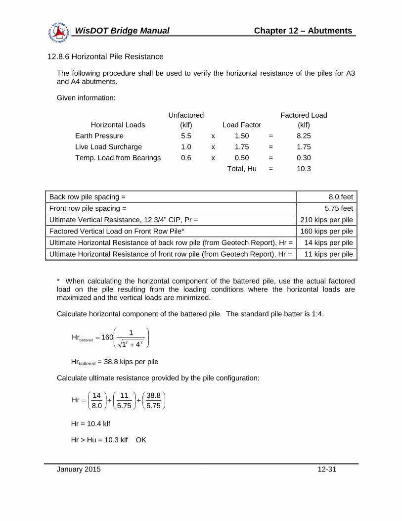
12.8.6 Horizontal Pile Resistance
The following procedure shall be used to verify the horizontal resistance of the piles for A3 and A4 abutments.
Given information:
Horizontal Loads Unfactored
(klf) Load Factor Factored Load
(klf) Earth Pressure 5.5 x 1.50 = 8.25 Live Load Surcharge 1.0 x 1.75 = 1.75 Temp. Load from Bearings 0.6 x 0.50 = 0.30
Total, Hu = 10.3
Back row pile spacing = 8.0 feet Front row pile spacing = 5.75 feet Ultimate Vertical Resistance, 12 3/4” CIP, Pr = 210 kips per pile Factored Vertical Load on Front Row Pile* 160 kips per pile Ultimate Horizontal Resistance of back row pile (from Geotech Report), Hr = 14 kips per pile Ultimate Horizontal Resistance of front row pile (from Geotech Report), Hr = 11 kips per pile
* When calculating the horizontal component of the battered pile, use the actual factored load on the pile resulting from the loading conditions where the horizontal loads are maximized and the vertical loads are minimized.
Calculate horizontal component of the battered pile. The standard pile batter is 1:4.
+=
22battered41
1160Hr
Hrbattered = 38.8 kips per pile
Calculate ultimate resistance provided by the pile configuration:
+
+
=
75.58.38
75.511
0.814Hr
Hr = 10.4 klf
Hr > Hu = 10.3 klf OK
WisDOT Bridge Manual Chapter 12 – Abutments
January 2015 12-32
12.9 Abutment Body Details
There are many different body sections that are utilized for each of the different abutment types. When designing these sections, it is inadvisable to use small and highly reinforced sections. As a general principle, it is better to use a lot of concrete and less reinforcing steel, thus making parts relatively massive and stiff. Adequate horizontal reinforcement and vertical contraction joints are essential to prevent cracking, especially when wing walls are poured monolithically with the abutment body.
The bottom of abutment bodies are normally constructed on a horizontal surface. However, abutments constructed on a horizontal surface may require one end of the body to be much higher than the opposite end due to the vertical geometry of the bridge. This sometimes requires an extremely long and high wing wall. For these extreme cases, the bottom of the abutment body can be stepped.
The berm in front of the body is held level even though the body is stepped. A minimum distance of 2.5 feet between the top of berm and the top of beam seat is allowed. Minimum ground cover as shown in the Standard Detail for Abutments must be maintained.
Stepping the bottom of the body may result in a longer bridge. This is usually more costly than holding the body level and using larger wings and beam seats. Stepped abutments are also more difficult to build. Engineering judgment must be exercised when determining if the bottom of the abutment should be level or stepped. Generally, if a standard wing wall design cannot be used, the bottom of the abutment body should be stepped.
12.9.1 Construction Joints
In a U-shaped abutment with no joint between the wings and the body, traffic tends to compact the fill against the three sides of the abutment. When the temperature drops, the abutment body concrete cannot shrink without tending to squeeze the warmer fill inside. The resistance of the fill usually exceeds the tensile or shearing strength of the body or wing, and cracks result.
If contraction joints are not provided in long abutment bodies, nature usually creates them. To prevent uncontrolled cracking in the body or cracking at the body-wing joint, body pours are limited to a maximum of 50 feet. Expansion joints are required at a maximum of 90 feet, as specified in LRFD [11.6.1.6].
WisDOT exception to AASHTO:
LRFD [11.6.1.6] specifies that contraction joints shall be provided at intervals not exceeding 30 feet for conventional retaining walls and abutments. However, WisDOT has not experienced significant problems with 50 feet and uses a maximum interval of 50 feet.
Shear keys are provided in construction joints to allow the center pour to maintain the beneficial stabilizing effects from the wings. The shear keys enable the end pours, with their counterfort action due to the attached wing, to provide additional stability to the center pour. Reinforcing steel should be extended through the joint.
WisDOT Bridge Manual Chapter 12 – Abutments
January 2015 12-33
In general, body construction joints are keyed to hold the parts in line. Water barriers are used to prevent leakage and staining. Steel girder superstructures generally permit a small movement at construction joints without cracking the concrete slab. In the case of concrete slab or prestressed concrete girder construction, a crack will frequently develop in the deck above the abutment construction joint. The designer should consider this when locating the construction joint.
12.9.2 Beam Seats
Because of the bridge deck cross-slopes or skewed abutments, it is necessary to provide beam seats of different elevations on the abutment. The tops of these beam seats are poured to precise elevations and are made level except when elastomeric bearing pads are used and grades are equal to or exceed 1%. For this case, the beam seat should be parallel to the bottom of girder or slab. Shrinkage and practical difficulties in obtaining good workmanship make it difficult to obtain the exact beam seat elevation.
When detailing abutments, the differences in elevations between adjacent beam seats are provided by sloping the top of the abutment between level beam seats. For steel girders, the calculation of beam seat elevations and use of shim plates is described on the Standard Plate Girder Details in Chapter 24.
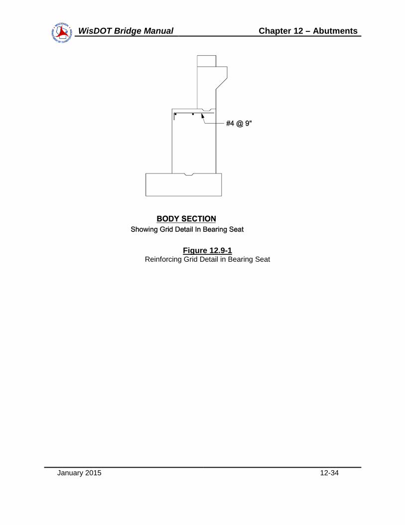
The tops of bearing seats are usually subjected to very large localized pressures under the bearings. Additional reinforcement directly under the bearings is sometimes necessary to prevent the formation of visible cracks or possible spalling of concrete. This additional reinforcement is required for seats that are stepped 4” or more when the standard body reinforcement is not sufficient to prevent the possibility of this cracking or spalling. A common detail includes a grid of #4 reinforcing bars bent down into the abutment body, as shown in Figure 12.9-1.
WisDOT Bridge Manual Chapter 12 – Abutments
January 2015 12-34
Figure 12.9-1 Reinforcing Grid Detail in Bearing Seat

WisDOT Bridge Manual Chapter 12 – Abutments
January 2015 12-35
12.10 Timber Abutments
Timber abutments consist of a single row of piling capped with timber or concrete, and backed with timber to retain the approach fill. The superstructure types are generally concrete slab or timber. Timber-backed abutments currently exist on Town Roads and County Highways where the abutment height does not preclude the use of timber backing.
Piles in bents are designed for combined axial load and bending moments. For analysis, the assumption is made that the piles are supported at their tops and are fixed 6 feet below the stream bed or original ground line. For cast-in-place concrete piling, the concrete core is designed to resist the axial load. The bending stress is resisted by the steel shell section. Due to the possibility of shell corrosion, steel reinforcement is placed in the concrete core equivalent to a 1/16-inch steel shell perimeter section loss. The reinforcement design is based on equal section moduli for the two conditions. Reinforcement details and bearing capacities are given on the Standard Detail for Pile Details. Pile spacing is generally limited to the practical span lengths for timber backing planks.
The requirements for tie rods and deadmen is a function of the abutment height. Tie rods with deadmen on body piling are used when the height of "freestanding" piles is greater than 12 feet for timber piling and greater than 15 feet for cast-in-place concrete and steel "HP" piling. The "freestanding" length of a pile is measured from the stream bed or berm to grade. If possible, all deadmen should be placed against undisturbed soil.
Commercial grade lumber as specified in AASHTO having a minimum flexural resistance of 1.2 ksi is utilized for the timber backing planks. The minimum recommended nominal thickness and width of timber backing planks are 3 and 10 inches, respectively. If nominal sizes are specified on the plans, analysis computations must be based on the dressed or finished sizes of the timber. Design computations can be used on the full nominal sizes if so stated on the bridge plans. For abutments constructed with cast-in-place concrete or steel "HP" piles, the timber planking is attached with 60d galvanized nails to timber nailing strips which are bolted to the piling, or between the flanges of “HP” piles.
WisDOT Bridge Manual Chapter 12 – Abutments
January 2015 12-36
12.11 Bridge Approach Design and Construction Practices
While most bridge approaches are reasonably smooth and require a minimum amount of maintenance, there are also rough bridge approaches with maintenance requirements. The bridge designer should be aware of design and construction practices that minimize bridge approach maintenance issues. Soils, design, construction and maintenance engineers must work together and are jointly responsible for efforts to eliminate rough bridge approaches.
An investigation of the foundation site is important for bridge design and construction. The soils engineer, using tentative grades and foundation site information, can provide advice on the depth of material to be removed, special embankment foundation drainage, surcharge heights, waiting periods, construction rates and the amount of post-construction settlement that can be anticipated. Some typical bridge approach problems include the following:
• Settlement of pavement at end of approach slab
• Uplift of approach slab at abutment caused from swelling soils or freezing
• Backfill settlement under flexible pavement
• Approach slab not adequately supported at the abutments
• Erosion due to water infiltration
Most bridge approach problems can be minimized during design and construction by considering the following:
• Embankment height, material and construction methods
• Subgrade, subbase and base material
• Drainage-runoff from bridge, surface drains and drainage channels
• Special approach slabs allowing for pavement expansion
Post-construction consolidation of material within the embankment foundation is the primary contributor to rough bridge approaches. Soils which consist predominantly of sands and gravels are least susceptible to consolidation and settlement. Soils with large amounts of shales, silts and plastic clays are highly susceptible to consolidation.
The following construction measures can be used to stabilize foundation materials:
• Consolidate the natural material. Allow sufficient time for consolidation under the load of the embankment. When site investigations indicate an excessive length of time is required, other courses of corrective action are available. Use of a surcharge fill is effective where the compressive stratum is relatively thin and sufficient time is available for consolidation.
WisDOT Bridge Manual Chapter 12 – Abutments
January 2015 12-37
• Remove the material either completely or partially. This procedure is practical if the foundation depth is less than 15 feet and above the water table.
• Use lightweight embankment materials. Lightweight materials (fly ash, expanded shale and cinders) have been used with apparent success for abutment embankment construction to lessen the load on the foundation materials.
Abutment backfill practices that help minimize either settlement or swell include the following:
• Use of select materials
• Placement of relatively thin 4- to 6-inch layers
• Strict control of moisture and density
• Proper compaction
• Installation of moisture barriers
It is generally recognized by highway and bridge engineers that bridge abutments cause relatively few of the problems associated with bridge approaches. Proper drainage needs to be provided to prevent erosion of embankment or subgrade material that could cause settlement of the bridge approach. It is essential to provide for the removal of surface water that leaks into the area behind the abutment by using weepholes and/or drain tile. In addition, water infiltration between the approach slab and abutment body and wings must be prevented.
Reinforced concrete approach slabs are the most effective means for controlling surface irregularities caused by settlement. It is also important to allow enough expansion movement between the approach slab and the approach pavement to prevent horizontal thrust on the abutment.
The bridge designer should determine if a structural approach slab is required and coordinate details with the roadway engineer. Usage of structural approach slabs is currently based on road functional classifications and considerations to traffic volumes (AADT), design speeds, and settlement susceptibility.
WisDOT policy item:
Structural approach slabs shall be used on all Interstate Highway bridges and U.S.H. bridges. Other locations can be considered with the approval of the Chief Structural Design Engineer.
Standards for Structural Approach Slab for Type A1, A3, and A4 Abutments and Structural Approach Slab Details for Type A1, A3, and A4 Abutments are available for guidance.

WisDOT Bridge Manual
This page intentionally left blank.