volume 3, issue 2, march – april 2014 issn 2278-6856 a...
TRANSCRIPT
International Journal of Emerging Trends & Technology in Computer Science (IJETTCS) Web Site: www.ijettcs.org Email: [email protected], [email protected]
Volume 3, Issue 2, March – April 2014 ISSN 2278-6856
Volume 3, Issue 2 March – April 2014 Page 131
Abstract: Multifocus Image Fusion is the process of fusing two or more registered images where the focus of the objects in each of the images is different. In this paper we present a hybrid approach for fusing two multifocus images. The resulting image will have higher clarity and resolution than the original images. The proposed approach is based on fuzzy logic and Discrete Wavelet Transform (DWT). The membership functions and rules for fuzzy logic have been formed appropriately to best suit the problem of fusion of multifocus images. DWT has been used to improve the performance as fuzzy logic is applied at every level of DWT to fuse the approximation coefficients. Detailed coefficients are fused by taking the maximum value. Common regions of both the images are retained in the fused image. Fuzzy logic is applied only on dissimilar pixels which speeds up the fusion process to a greater extent. Keywords: Fuzzy Logic, Image Fusion, Multifocus Images, Discrete Wavelet Transform. 1. INTRODUCTION Image fusion is the process of combining two or more aligned images. Each input image contains information of the same scene but the important information present in the images is spread across several images and will be complementary in nature. The fused image will contain the essential features of all the images and it is more useful than any of the input images. Various types of images are fused together to obtain useful information. Therefore image fusion is used in many areas. Some of them include (i) Fusion of multi-focus images (ii) Fusion of multiple sensor images obtained from sensors like visible range sensors, infrared sensors and thermal sensors (iii) Fusion of medical images like Magnetic Resonance Images (MRI), Computed Tomography (CT) images and Positron Emission Tomography (PET) images (iv) Fusion of remotely sensed images obtained at different times of the day (v) Fusion of maps with satellite images. Various approaches have been developed for performing image fusion, each with their own merits and limitations. Though it is infeasible to develop a robust approach to handle all the types of image fusion, techniques are available to cater to the specific type of image fusion. Image fusion techniques can be broadly classified as (i) Pixel based: Fusion is performed pixel by pixel (ii) Feature based: Features are extracted from both the images and best features appear in the fused image
(iii) Decision based: Fusion of high-level information where decisions are based on the outputs from individual sensors [1]. The brute force techniques used for image fusion are (i) Simple averaging and (ii) Weighted averaging. Using wavelets for image fusion has been discussed in detail in [2]. Image fusion based on Principal Component Analysis (PCA) and wavelets is performed in [3]. A comparison of different Image Fusion Techniques is performed in [4] and it is concluded that image fusion based on combination of DWT and PCA with morphological processing will improve the image fusion quality. A comparative image fusion analysis of infrared and visible band images is performed in [5] using image fusion methods like Total Probability Density Function, PCA, Laplacian Pyramid, Filter-Subtract-Decimate Hierarchical Pyramid, Ratio Pyramid, Gradient Pyramid, DWT, Shift Invariant DWT, Contrast Pyramid, Morphological Pyramid and Bio-inspired image fusion. Application of Discrete Cosine Transform (DCT) for image fusion is discussed in [6]. Fuzzy Logic (FL) is also used for image fusion by many developers. More information on FL is discussed in the following section. Hybrid approaches are also developed using a combination of two or more of the above mentioned techniques. In this paper, a novel hybrid approach is presented for multifocus image fusion using FL and DWT. 1.1 Fuzzy Logic The fuzzy logic technique is now being widely used for image fusion. The reason is that the logic used for performing image fusion is fuzzy rather than crisp. FL approaches are used where there is uncertainty and no mathematical relations are easily available [7]. FL was proposed by Zadeh [8] and is widely used in various fields. Human expertise is better applied to select the best regions of the input images and fuse them in the output image. FL is a tool for expressing human knowledge as a set of rules based on the decisions to be taken. Fuzzy image processing using Type-1 Fuzzy Logic (T1FL) has three main stages: (i) Image fuzzification, (ii) Inference system and (iii) Image defuzzification [9], [10]. During the fuzzification process, the input values are fuzzified using fuzzy sets and membership functions. The membership function associates a degree of belongingness of a crisp value to a fuzzy set. The type of membership functions such as triangular, trapezoidal, Gaussian etc. must be defined for fuzzy sets based on the input and
A Novel Hybrid Approach for Multi-focus Image Fusion using Fuzzy Logic and Wavelets
Myna.A.N.1, J.Prakash2
1M.S..Ramaiah Institute of Technology, Research Scholar, Bangalore Institute of Technology
2Bangalore Institute of Technology, Bangalore
International Journal of Emerging Trends & Technology in Computer Science (IJETTCS) Web Site: www.ijettcs.org Email: [email protected], [email protected]
Volume 3, Issue 2, March – April 2014 ISSN 2278-6856
Volume 3, Issue 2 March – April 2014 Page 132
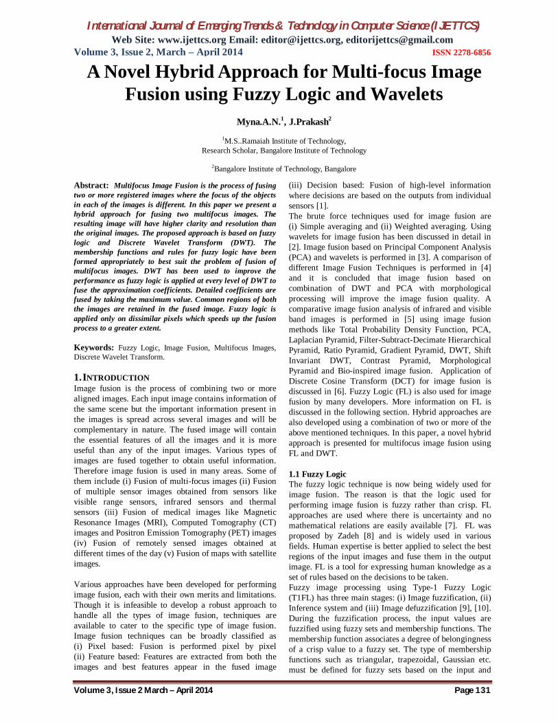
output domains. Inference system consists of a set of rules to convert the fuzzified inputs to fuzzified output. The rules are evaluated based on the fuzzy operators defined on the fuzzy sets. Rules and membership functions form the essence of fuzzy logic and are domain dependent. Defuzzification process is used to convert the fuzzy output of the fuzzy inference system into crisp output values. Fuzzy logic based image fusion is gaining momentum recently. Neuro fuzzy logic approach using MATLAB toolbox has been experimented in [7], [11] and [12]. Fuzzy membership functions and rules based on coefficients and the information entropy is discussed in [13]. Fusion of CT and MRI images using fuzzy logic is discussed in [14] by concluding that there is a need to fuse the effective information in order to provide more useful information for clinical diagnosis. 1.2 Discrete Wavelet Transforms Wavelet decomposition of the images is used due to its inherent multiresolution character. Discrete Wavelet Transform (DWT) has been used in the proposed approach to reduce the size of the image at each level. An image of resolution 2k x 2k pixels at level L reduces to size 2k-1x2k-1 pixels at level L+1. At each level the image is decomposed into four subimages obtained by applying low-pass filter L and a high-pass filter H working along the image rows and columns. Figure 1 shows the DWT decomposition at level 1 and level 2 respectively.
LL1
HL1
LL2 HL2
HL1
LH2 HH2
LH1
HH1 LH1 HH1
(a) Level 1 (b) Level 2 Figure 1 Image Decomposition using DWT
‘LL’ corresponds to the approximation coefficients of the image which is used for further decomposition. ‘LH’ corresponds to the vertical coefficients, ‘HL’ corresponds to the horizontal coefficients and ‘HH’ corresponds to the diagonal coefficients of the image. These subimages can be combined together to restore the image at the previous level [15]. Many researchers have performed image fusion using this multiresolution characteristic of DWT. The use of DWT in image fusion is detailed in [16]. A wavelet based approach of image fusion using PCA and morphological processing is developed in [17]. An introduction and review of DWT based image fusion techniques is given in [18] by concluding that schemes that combine standard methods with wavelet transforms produce superior
results. Comparison of activity level of spatial frequency for the fusion of detailed coefficients is used in [19]. A region based multiresolution image fusion scheme using fuzzy region feature is presented in [20] where the images are segmented into important regions, subimportant and background regions and the fusion is performed in fuzzy space. 1.3 Multi-focus Image Fusion The images obtained using CCD cameras do not contain all relevant objects “in focus”. This is because of the limited depth-of-focus of optical lenses [21]. Multi-focus image fusion takes as input a set of images where point of focus in each image is different. The focused part of the image will be more clear compared to the out of focus region. These images are fused together to obtain a single image where all the regions appear to be in focus. The techniques developed for multi-focus image fusion thus concentrate on extracting the clear regions from the input images. Fisher classifier is used in [21] to classify the pixels as in focus or out of focus. Fuzzy logic is further used for classifying a few misclassified regions. Fuzzy logic is also used in [9] to perform multi-focus image fusion. 1.4 Organization of the Paper In this paper, section 1 gives an introduction on image fusion and the different techniques used for image fusion. It also gives a brief introduction on fuzzy logic and DWT. Section 2 presents the proposed approach algorithm and also describes the Fuzzy Logic System (FLS) and fuzzy rules used. Section 3 describes the various quality metrics used to evaluate the image fusion results. Section 4 evaluates the results obtained using the proposed approach and compares with the results of other techniques. Section 5 gives the conclusion and scope for future work. 2. PROPOSED APPROACH The proposed approach uses the pixel based method of image fusion to fuse multi-focus images using fuzzy logic and DWT. 2.1 Proposed Algorithm Step 1: Input two multi-focus images.
Step 2: Extract the common regions of the images
which act as background in the fused image by taking only those pixels which have same value and copy these pixels to the output image.
Step 3: Apply DWT on the input images upto the desired level.
Step 4: Repeat steps 5 to 10 at each level of DWT.
Step 5: Perform background extraction as described in step 2 using the approximation coefficients
International Journal of Emerging Trends & Technology in Computer Science (IJETTCS) Web Site: www.ijettcs.org Email: [email protected], [email protected]
Volume 3, Issue 2, March – April 2014 ISSN 2278-6856
Volume 3, Issue 2 March – April 2014 Page 133
and save it as the intermediate fused image IF.
Step 6: Copy the remaining pixels of the approximation coefficients as inputs to the FLS.
Step 7: Obtain the output pixel values using fuzzy inference system.
Step 8: Copy the output values to their corresponding locations in IF.
Step 9: Fuse the detailed coefficients by selecting the maximum value of the two inputs.
Step 10: Apply Inverse Discrete Wavelet Transform (IDWT) on the fused approximation coefficients and detailed coefficients.
Step 11: At the input level, copy only the foreground pixels to the output image.
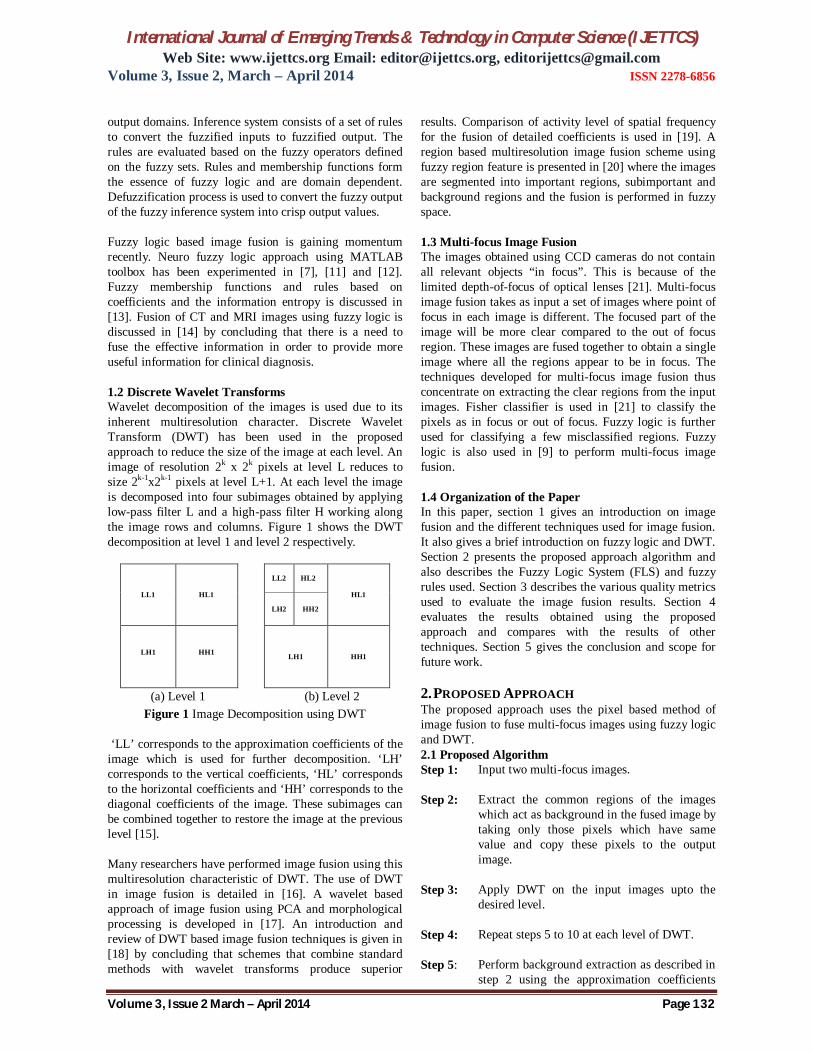
2.2 Fuzzy Logic System The block diagram of the proposed approach uses the FLS as shown in Figure 2. Mamdani type fuzzy inference system which comprises of two inputs and one output is used. The two inputs represent the pixel values from two input images. The Fuzzy Inference System (FIS) uses the rule base and evaluates the fuzzified output. Mamdani FIS uses maximum value to evaluate ‘OR’ operator in the rule and minimum value to evaluate ‘AND’ operator. The output is a fuzzy value and is defuzzified using centroid method. 2.3 Fuzzy Membership Functions
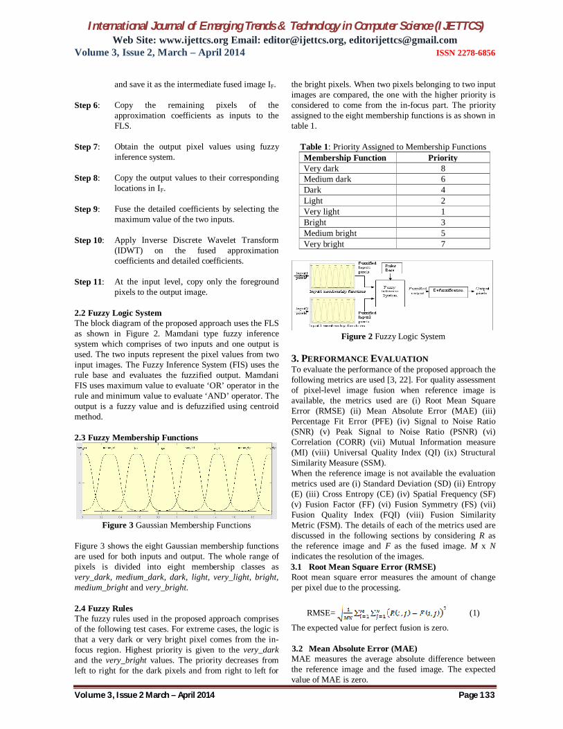
Figure 3 Gaussian Membership Functions
Figure 3 shows the eight Gaussian membership functions are used for both inputs and output. The whole range of pixels is divided into eight membership classes as very_dark, medium_dark, dark, light, very_light, bright, medium_bright and very_bright. 2.4 Fuzzy Rules The fuzzy rules used in the proposed approach comprises of the following test cases. For extreme cases, the logic is that a very dark or very bright pixel comes from the in-focus region. Highest priority is given to the very_dark and the very_bright values. The priority decreases from left to right for the dark pixels and from right to left for
the bright pixels. When two pixels belonging to two input images are compared, the one with the higher priority is considered to come from the in-focus part. The priority assigned to the eight membership functions is as shown in table 1.
Table 1: Priority Assigned to Membership Functions Membership Function Priority Very dark 8 Medium dark 6 Dark 4 Light 2 Very light 1 Bright 3 Medium bright 5 Very bright 7
Figure 2 Fuzzy Logic System
3. PERFORMANCE EVALUATION To evaluate the performance of the proposed approach the following metrics are used [3, 22]. For quality assessment of pixel-level image fusion when reference image is available, the metrics used are (i) Root Mean Square Error (RMSE) (ii) Mean Absolute Error (MAE) (iii) Percentage Fit Error (PFE) (iv) Signal to Noise Ratio (SNR) (v) Peak Signal to Noise Ratio (PSNR) (vi) Correlation (CORR) (vii) Mutual Information measure (MI) (viii) Universal Quality Index (QI) (ix) Structural Similarity Measure (SSM). When the reference image is not available the evaluation metrics used are (i) Standard Deviation (SD) (ii) Entropy (E) (iii) Cross Entropy (CE) (iv) Spatial Frequency (SF) (v) Fusion Factor (FF) (vi) Fusion Symmetry (FS) (vii) Fusion Quality Index (FQI) (viii) Fusion Similarity Metric (FSM). The details of each of the metrics used are discussed in the following sections by considering R as the reference image and F as the fused image. M x N indicates the resolution of the images. 3.1 Root Mean Square Error (RMSE) Root mean square error measures the amount of change per pixel due to the processing.
RMSE= (1)
The expected value for perfect fusion is zero. 3.2 Mean Absolute Error (MAE) MAE measures the average absolute difference between the reference image and the fused image. The expected value of MAE is zero.
International Journal of Emerging Trends & Technology in Computer Science (IJETTCS) Web Site: www.ijettcs.org Email: [email protected], [email protected]
Volume 3, Issue 2, March – April 2014 ISSN 2278-6856
Volume 3, Issue 2 March – April 2014 Page 134
MAE= (2)
3.3 Percentage Fit Error (PFE) It is the percentage of the ratio of the norm of the difference image and the norm of the reference image. It is expected to be zero percent for ideal fusion.
PFE= (3)
3.4 Signal to Noise Ratio (SNR) It is the ratio of the sum of the square of the reference image to the sum of the square of the estimated error. A larger value of SNR indicates better fusion.
SNR=20log10 (4)
3.5 Peak Signal to Noise Ratio (PSNR)
PSNR=20log10 (5)
where L is the number of gray levels in the image. A larger value indicates better fusion 3.6 Correlation (CORR)
CORR= (6) where CR= CF= CRF=
Ideal value of correlation is 1. Larger value indicates better image quality. 3.7 Mutual Information Measure (MI) Mutual Information measure computes the information of one image in another. IRF is the mutual information of R and F.
IRF= (7) where PR(x) and PF(y) are the Probability Density Functions (PDF) of the individual images and PRF(x,y) is joint PDF. Larger value indicates better quality. 3.8 Universal Quality Index (QI)
QI= (8)
where µR and µF are the mean values of R and F, and
are the variance values of R and F, is the covariance between R and F. The range of QI is -1 to +1. A value of 1 indicates ideal fusion. 3.9 Measure of Structural Similarity (SSM) It computes the measure of similarity between two images, M and N. Its value ranges from -1 to +1. If both images are identical, then SSM=1.
SSM= (9)
where µR and µF are the mean values of R and F, and
are the variance values of R and F, is the covariance between R and F, C1 and C2 are constants included to avoid instability when their corresponding co-operands are zero. Larger value implies better fusion. The following metrics are used when reference image is not available. I1 and I2 are the input source images and F is the fused image. 3.10 Standard Deviation (SD)
σ = (10)
where = hF(i) is the normalized histogram of F and L is the number of frequency bins in the histogram. A larger value indicates good fusion as it is a measure of the contrast of the image. 3.11 Entropy (E) Entropy is used to measure the information content of an image.
E= - (11) where p contains the histogram count of the fused image F. Larger value implies better fusion. 3.12 Cross Entropy (CE) Cross Entropy measures the similarity in information content between input images and fused image.
CE(I1,I2,F) = (12) where CE(P,Q)=
Low cross entropy indicates better fusion quality. 3.13 Spatial Frequency (SF)
SF= (13)
where RF is the row frequency and CF is the column frequency.
RF=
CF=
Larger value indicates better fusion. It indicates the activity of the image in the spatial domain. 3.14 Fusion Factor (FF)
FF= (14)
International Journal of Emerging Trends & Technology in Computer Science (IJETTCS) Web Site: www.ijettcs.org Email: [email protected], [email protected]
Volume 3, Issue 2, March – April 2014 ISSN 2278-6856
Volume 3, Issue 2 March – April 2014 Page 135
where is the mutual information of I1 and F, is the mutual information of I2 and F. Larger value of FF indicates that good amount of information is present in the fused images. However it does not imply that the information is symmetrically fused. 3.15 Fusion Symmetry (FS) FS= abs (15)
where is the mutual information of I1 and F, is the mutual information of I2 and F. A low FS value indicates that the fused image derives features from both the input images. 3.16 Fusion Quality Index (FQI) FQI= (16)
where λ(w) = computed over a window, c(w) is the
normalized version of C(w) where C(w)=max over a window and Q(Ii, F) is the quality index over a window for a given source image and fused image. Larger value indicates better fusion. 3.17 Fusion Similarity Metric (FSM) FSM=
(17)
where sim
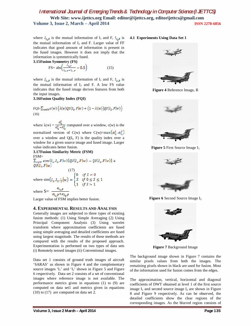
where S= Larger value of FSM implies better fusion. 4. EXPERIMENTAL RESULTS AND ANALYSIS Generally images are subjected to three types of existing fusion methods: (1) Using Simple Averaging (2) Using Principal Component Analysis (3) Using wavelet transform where approximation coefficients are fused using simple averaging and detailed coefficients are fused using largest magnitude. The results of these methods are compared with the results of the proposed approach. Experimentation is performed on two types of data sets (i) Remotely sensed images (ii) Conventional images. Data set 1 consists of ground truth images of aircraft ‘SARAS’ as shown in Figure 4 and the complementary source images ‘I1’ and ‘I2’ shown in Figure 5 and Figure 6 respectively. Data set 2 consists of a set of conventional images where reference image is not available. The performance metrics given in equations (1) to (9) are computed on data set1 and metrics given in equations (10) to (17) are computed on data set 2.
4.1 Experiments Using Data Set 1
Figure 4 Reference Image, R
Figure 5 First Source Image I1
Figure 6 Second Source Image I2
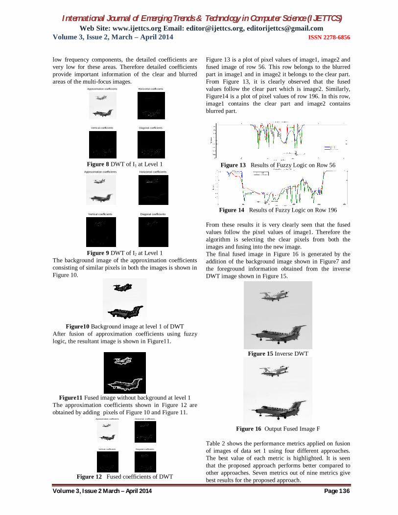
Figure 7 Background Image
The background image shown in Figure 7 contains the similar pixels values from both the images. The remaining pixels shown in black are used for fusion. Most of the information used for fusion comes from the edges. The approximation, vertical, horizontal and diagonal coefficients of DWT obtained at level 1 of the first source image I1 and second source image I2 are shown in Figure 8 and Figure 9 respectively. As can be observed, the detailed coefficients show the clear regions of the corresponding images. As the blurred region consists of
International Journal of Emerging Trends & Technology in Computer Science (IJETTCS) Web Site: www.ijettcs.org Email: [email protected], [email protected]
Volume 3, Issue 2, March – April 2014 ISSN 2278-6856
Volume 3, Issue 2 March – April 2014 Page 136
low frequency components, the detailed coefficients are very low for these areas. Therefore detailed coefficients provide important information of the clear and blurred areas of the multi-focus images.
Approximation coefficients Horizontal coefficients
Vertical coefficients Diagonal coefficients
Figure 8 DWT of I1 at Level 1
Approximation coefficients Horizontal coefficients
Vertical coefficients Diagonal coefficients
Figure 9 DWT of I2 at Level 1
The background image of the approximation coefficients consisting of similar pixels in both the images is shown in Figure 10.
Figure10 Background image at level 1 of DWT
After fusion of approximation coefficients using fuzzy logic, the resultant image is shown in Figure11.
Figure11 Fused image without background at level 1
The approximation coefficients shown in Figure 12 are obtained by adding pixels of Figure 10 and Figure 11.
Approximation coefficients Horizontal coefficients
Vertical coefficients Diagonal coefficients
Figure 12 Fused coefficients of DWT
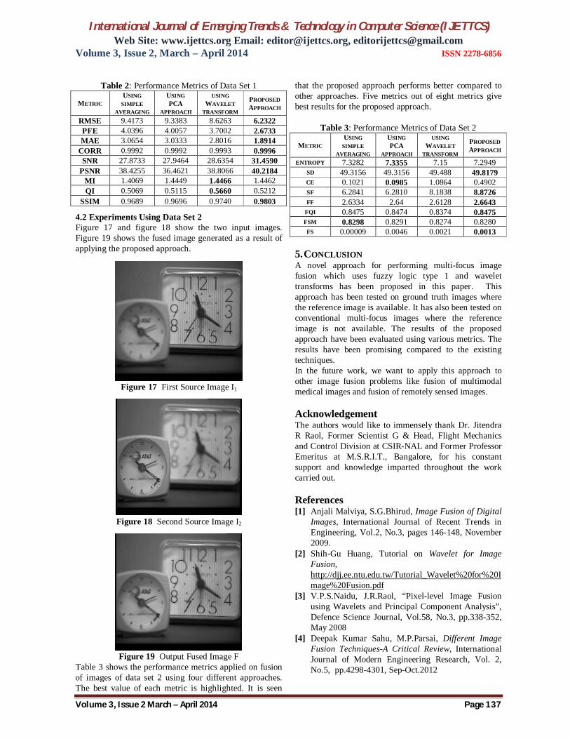
Figure 13 is a plot of pixel values of image1, image2 and fused image of row 56. This row belongs to the blurred part in image1 and in image2 it belongs to the clear part. From Figure 13, it is clearly observed that the fused values follow the clear part which is image2. Similarly, Figure14 is a plot of pixel values of row 196. In this row, image1 contains the clear part and image2 contains blurred part.
Figure 13 Results of Fuzzy Logic on Row 56
Figure 14 Results of Fuzzy Logic on Row 196
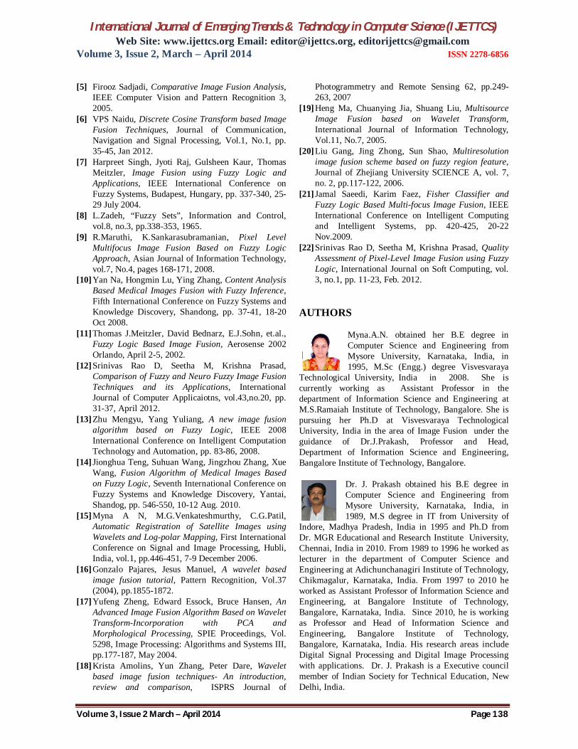
From these results it is very clearly seen that the fused values follow the pixel values of image1. Therefore the algorithm is selecting the clear pixels from both the images and fusing into the new image. The final fused image in Figure 16 is generated by the addition of the background image shown in Figure7 and the foreground information obtained from the inverse DWT image shown in Figure 15.
Figure 15 Inverse DWT
Figure 16 Output Fused Image F
Table 2 shows the performance metrics applied on fusion of images of data set 1 using four different approaches. The best value of each metric is highlighted. It is seen that the proposed approach performs better compared to other approaches. Seven metrics out of nine metrics give best results for the proposed approach.
International Journal of Emerging Trends & Technology in Computer Science (IJETTCS) Web Site: www.ijettcs.org Email: [email protected], [email protected]
Volume 3, Issue 2, March – April 2014 ISSN 2278-6856
Volume 3, Issue 2 March – April 2014 Page 137
Table 2: Performance Metrics of Data Set 1
METRIC USING
SIMPLE AVERAGING
USING PCA
APPROACH
USING WAVELET
TRANSFORM
PROPOSED APPROACH
RMSE 9.4173 9.3383 8.6263 6.2322 PFE 4.0396 4.0057 3.7002 2.6733 MAE 3.0654 3.0333 2.8016 1.8914
CORR 0.9992 0.9992 0.9993 0.9996 SNR 27.8733 27.9464 28.6354 31.4590
PSNR 38.4255 36.4621 38.8066 40.2184 MI 1.4069 1.4449 1.4466 1.4462 QI 0.5069 0.5115 0.5660 0.5212
SSIM 0.9689 0.9696 0.9740 0.9803
4.2 Experiments Using Data Set 2 Figure 17 and figure 18 show the two input images. Figure 19 shows the fused image generated as a result of applying the proposed approach.
Figure 17 First Source Image I1
Figure 18 Second Source Image I2
Figure 19 Output Fused Image F
Table 3 shows the performance metrics applied on fusion of images of data set 2 using four different approaches. The best value of each metric is highlighted. It is seen
that the proposed approach performs better compared to other approaches. Five metrics out of eight metrics give best results for the proposed approach.
Table 3: Performance Metrics of Data Set 2
METRIC USING
SIMPLE AVERAGING
USING PCA
APPROACH
USING WAVELET
TRANSFORM
PROPOSED APPROACH
ENTROPY 7.3282 7.3355 7.15 7.2949 SD 49.3156 49.3156 49.488 49.8179 CE 0.1021 0.0985 1.0864 0.4902 SF 6.2841 6.2810 8.1838 8.8726 FF 2.6334 2.64 2.6128 2.6643
FQI 0.8475 0.8474 0.8374 0.8475 FSM 0.8298 0.8291 0.8274 0.8280 FS 0.00009 0.0046 0.0021 0.0013
5. CONCLUSION A novel approach for performing multi-focus image fusion which uses fuzzy logic type 1 and wavelet transforms has been proposed in this paper. This approach has been tested on ground truth images where the reference image is available. It has also been tested on conventional multi-focus images where the reference image is not available. The results of the proposed approach have been evaluated using various metrics. The results have been promising compared to the existing techniques. In the future work, we want to apply this approach to other image fusion problems like fusion of multimodal medical images and fusion of remotely sensed images. Acknowledgement The authors would like to immensely thank Dr. Jitendra R Raol, Former Scientist G & Head, Flight Mechanics and Control Division at CSIR-NAL and Former Professor Emeritus at M.S.R.I.T., Bangalore, for his constant support and knowledge imparted throughout the work carried out. References [1] Anjali Malviya, S.G.Bhirud, Image Fusion of Digital
Images, International Journal of Recent Trends in Engineering, Vol.2, No.3, pages 146-148, November 2009.
[2] Shih-Gu Huang, Tutorial on Wavelet for Image Fusion, http://djj.ee.ntu.edu.tw/Tutorial_Wavelet%20for%20Image%20Fusion.pdf
[3] V.P.S.Naidu, J.R.Raol, “Pixel-level Image Fusion using Wavelets and Principal Component Analysis”, Defence Science Journal, Vol.58, No.3, pp.338-352, May 2008
[4] Deepak Kumar Sahu, M.P.Parsai, Different Image Fusion Techniques-A Critical Review, International Journal of Modern Engineering Research, Vol. 2, No.5, pp.4298-4301, Sep-Oct.2012
International Journal of Emerging Trends & Technology in Computer Science (IJETTCS) Web Site: www.ijettcs.org Email: [email protected], [email protected]
Volume 3, Issue 2, March – April 2014 ISSN 2278-6856
Volume 3, Issue 2 March – April 2014 Page 138
[5] Firooz Sadjadi, Comparative Image Fusion Analysis, IEEE Computer Vision and Pattern Recognition 3, 2005.
[6] VPS Naidu, Discrete Cosine Transform based Image Fusion Techniques, Journal of Communication, Navigation and Signal Processing, Vol.1, No.1, pp. 35-45, Jan 2012.
[7] Harpreet Singh, Jyoti Raj, Gulsheen Kaur, Thomas Meitzler, Image Fusion using Fuzzy Logic and Applications, IEEE International Conference on Fuzzy Systems, Budapest, Hungary, pp. 337-340, 25-29 July 2004.
[8] L.Zadeh, “Fuzzy Sets”, Information and Control, vol.8, no.3, pp.338-353, 1965.
[9] R.Maruthi, K.Sankarasubramanian, Pixel Level Multifocus Image Fusion Based on Fuzzy Logic Approach, Asian Journal of Information Technology, vol.7, No.4, pages 168-171, 2008.
[10] Yan Na, Hongmin Lu, Ying Zhang, Content Analysis Based Medical Images Fusion with Fuzzy Inference, Fifth International Conference on Fuzzy Systems and Knowledge Discovery, Shandong, pp. 37-41, 18-20 Oct 2008.
[11] Thomas J.Meitzler, David Bednarz, E.J.Sohn, et.al., Fuzzy Logic Based Image Fusion, Aerosense 2002 Orlando, April 2-5, 2002.
[12] Srinivas Rao D, Seetha M, Krishna Prasad, Comparison of Fuzzy and Neuro Fuzzy Image Fusion Techniques and its Applications, International Journal of Computer Applicaiotns, vol.43,no.20, pp. 31-37, April 2012.
[13] Zhu Mengyu, Yang Yuliang, A new image fusion algorithm based on Fuzzy Logic, IEEE 2008 International Conference on Intelligent Computation Technology and Automation, pp. 83-86, 2008.
[14] Jionghua Teng, Suhuan Wang, Jingzhou Zhang, Xue Wang, Fusion Algorithm of Medical Images Based on Fuzzy Logic, Seventh International Conference on Fuzzy Systems and Knowledge Discovery, Yantai, Shandog, pp. 546-550, 10-12 Aug. 2010.
[15] Myna A N, M.G.Venkateshmurthy, C.G.Patil, Automatic Registration of Satellite Images using Wavelets and Log-polar Mapping, First International Conference on Signal and Image Processing, Hubli, India, vol.1, pp.446-451, 7-9 December 2006.
[16] Gonzalo Pajares, Jesus Manuel, A wavelet based image fusion tutorial, Pattern Recognition, Vol.37 (2004), pp.1855-1872.
[17] Yufeng Zheng, Edward Essock, Bruce Hansen, An Advanced Image Fusion Algorithm Based on Wavelet Transform-Incorporation with PCA and Morphological Processing, SPIE Proceedings, Vol. 5298, Image Processing: Algorithms and Systems III, pp.177-187, May 2004.
[18] Krista Amolins, Yun Zhang, Peter Dare, Wavelet based image fusion techniques- An introduction, review and comparison, ISPRS Journal of
Photogrammetry and Remote Sensing 62, pp.249-263, 2007
[19] Heng Ma, Chuanying Jia, Shuang Liu, Multisource Image Fusion based on Wavelet Transform, International Journal of Information Technology, Vol.11, No.7, 2005.
[20] Liu Gang, Jing Zhong, Sun Shao, Multiresolution image fusion scheme based on fuzzy region feature, Journal of Zhejiang University SCIENCE A, vol. 7, no. 2, pp.117-122, 2006.
[21] Jamal Saeedi, Karim Faez, Fisher Classifier and Fuzzy Logic Based Multi-focus Image Fusion, IEEE International Conference on Intelligent Computing and Intelligent Systems, pp. 420-425, 20-22 Nov.2009.
[22] Srinivas Rao D, Seetha M, Krishna Prasad, Quality Assessment of Pixel-Level Image Fusion using Fuzzy Logic, International Journal on Soft Computing, vol. 3, no.1, pp. 11-23, Feb. 2012.
AUTHORS
Myna.A.N. obtained her B.E degree in Computer Science and Engineering from Mysore University, Karnataka, India, in 1995, M.Sc (Engg.) degree Visvesvaraya
Technological University, India in 2008. She is currently working as Assistant Professor in the department of Information Science and Engineering at M.S.Ramaiah Institute of Technology, Bangalore. She is pursuing her Ph.D at Visvesvaraya Technological University, India in the area of Image Fusion under the guidance of Dr.J.Prakash, Professor and Head, Department of Information Science and Engineering, Bangalore Institute of Technology, Bangalore.
Dr. J. Prakash obtained his B.E degree in Computer Science and Engineering from Mysore University, Karnataka, India, in 1989, M.S degree in IT from University of
Indore, Madhya Pradesh, India in 1995 and Ph.D from Dr. MGR Educational and Research Institute University, Chennai, India in 2010. From 1989 to 1996 he worked as lecturer in the department of Computer Science and Engineering at Adichunchanagiri Institute of Technology, Chikmagalur, Karnataka, India. From 1997 to 2010 he worked as Assistant Professor of Information Science and Engineering, at Bangalore Institute of Technology, Bangalore, Karnataka, India. Since 2010, he is working as Professor and Head of Information Science and Engineering, Bangalore Institute of Technology, Bangalore, Karnataka, India. His research areas include Digital Signal Processing and Digital Image Processing with applications. Dr. J. Prakash is a Executive council member of Indian Society for Technical Education, New Delhi, India.