optimization of fir filters design using genetic algorithm · web site: email: [email protected],...
TRANSCRIPT
Web Site: www.ijettcs.org Email: [email protected], [email protected] Volume 1, Issue 3, September – October 2012 ISSN 2278-6856
Volume 1, Issue 3, September – October 2012 Page 228
Abstract: Digital filters are an essential part of DSP. In fact, their extraordinary performance is one of the key reasons that DSP has become so popular. The purpose of the filters is to allow some frequencies to pass unaltered, while completely blocking others. The digital filters are mainly used for two purposes: separation of signals that have been combined, and restoration of signals that have been distorted in some way. In this present work, FIR filter is designed using Genetic Algorithm (GM) and its comparison is done with Blackman, Parks McClellan in MATLAB. The comparisons are done to improve the magnitude response, phase variation and phase delay. The response is studied by keeping values of fixed order, crossover probability and mutation probability. Out of all three techniques, GA offers a quick, simple and automatic method of designing low pass FIR filters that are very close to optimum in terms of magnitude response, frequency response and in terms of phase variation. FIR filter design using Hamming window provides good magnitude response but transition bandwidth is very high, large phase deviation and lack of control of
critical frequencies p and s. To overcome this problem, Parks McClellan is used but as the order of filter is increased, this method is not suitable. Therefore, to solve all these problems, GA is used. With the help of GA, the numbers of operations in design process are reduced and coefficient calculation is easily realized. Keywords: Parks McClellan, DSP, FIR, GA, Blackman
1. INTRODUCTION
Digital Signal Processing (DSP) is one of the most powerful technologies that are shaping science and engineering in the twenty-first century. Revolutionary changes have already been made in a broad range of fields: communications, medical imaging, radar and sonar, and high fidelity music reproduction, to name just a few. Each of these areas has developed a comprehensive DSP technology, with its own algorithms, mathematics, and specialized techniques. Analog (electronic) filters can be used for these tasks, as these are cheap, fast, and have a large dynamic range in both amplitude and frequency; however, digital filters are vastly superior in the level of performance. In this work, a type of digital filter i.e., FIR filter is used to separate one band of frequencies from another. The primary attribute of FIR filters is their
stability. This is because they are carried out by convolution rather than recursion. FIR filters are linear phase filters and both phase delay and group delays are constant in these filters [1].
1.2 Filter and design techniques Filtering is a process by which the frequency spectrum of a signal can be modified, reshaped or manipulated to achieve some desired objectives. These are as under [2]: To eliminate noise that may contaminate the signal, to remove signal distortion which may be due to imperfection in the transmission channel, to resolve the signal into its frequency component, to demodulate the signal which was modulated at the transmitter side, to convert digital signals into analog signals and to limit the bandwidth of a signal.
1.3 Finite Impulse Response (FIR) Filter A Finite Impulse Response (FIR) digital filter is one whose impulse response is of finite duration. The impulse response is "finite" because there is no feedback in the filter. If we put in an impulse (that is, a single "1" sample followed by many "0" samples), zeroes will eventually come out after the "1" sample has made its way in the delay line past all the coefficients. FIR (Finite Impulse Response) filters are implemented using a finite number "n" delay taps on a delay line and "n" computation coefficients to compute the algorithm (filter) function. The above structure is non-recursive, a repetitive delay-and-add format, and is most often used to produce FIR filters. This structure depends upon each sample of new and present value data. The number of taps (delays) and values of the computation coefficients (h0,h1,…...hn) are selected to "weight" the data being shifted down the delay line to create the desired amplitude response of the filter. In this configuration, there are no feedback paths to cause instability. The calculation of coefficients is not constrained to particular values and can be used to implement filter functions that do not have a linear system equivalent. More taps increase the steepness of the filter roll-off while increasing calculation time (delay) and for high order filters, limiting bandwidth. This can be stated mathematically as:
Optimization of FIR Filters Design using Genetic Algorithm
1Pardeep Kaur, 2Simarpreet Kaur
1,2Punjab Technical University, Baba Banda Singh Bahadur Engineering College, Fatehgarh Sahib 140407, Punjab, India
Web Site: www.ijettcs.org Email: [email protected], [email protected] Volume 1, Issue 3, September – October 2012 ISSN 2278-6856
Volume 1, Issue 3, September – October 2012 Page 229
Where = Response of Linear Time Invariant (LTI) system.
= Input signal = Unit sample response
N = No. of signal samples FIR filters are simple to design and they are guaranteed to be bounded input-bounded output (BIBO) stable. By designing the filter taps to be symmetrical about the center tap position, an FIR filter can be guaranteed to have linear phase response. This is a desirable property for many applications such as music and video processing.
1.4 Infinite Impulse Response (IIR) Filter IIR filter is one whose impulse response is infinite [3]. Impulse response is infinite because there is feedback in the filter. This permits the approximation of many waveforms or transfer functions that can be expressed as an infinite recursive series. These implementations are referred to as Infinite Impulse Response (IIR) filters. The functions are infinite recursive because they use previously calculated values in future calculations to feedback in hardware systems. IIR filters can be mathematically represented as:
Where is the kth feedback tap . M is the number of feed-back taps in the IIR filter and N is the number of feed-forward taps. IIR Filters are useful for high-speed designs because they typically require a lower number of multiply compared to FIR filters. IIR filters have lower side lobes in stop band as compared to FIR filters. Unfortunately, IIR filters do not have linear phase and they can be unstable if not designed properly. IIR filters are very sensitive to filter coefficient quantization errors that occur due to use of a finite number of bits to represent the filter coefficients. One way to reduce this sensitivity is to use a cascaded design. That is, the IIR filter is implemented as a series of lower-order IIR filters as opposed to one high-order.
1.5 Advantages of FIR over IIR Filter
FIR filters have the following advantages over the IIR filters
1. FIR filters are linear phase filters, which is useful in speech processing.
2. FIR filters are always stable because all the poles are within the unit circle.
3. The designing methods are generally linear for FIR filters.
4. The start-up transitions have finite duration in FIR filters.
5. Round off noise can be made small by employing non-recursive technique of realization.
1.6 The Magnitude and phase response of the FIR filter:
We know that DTFT of a finite sequence h (n) is given by [4]
h(n)DTFT(e H j )
or )M-1
j -j nT
n 0
H (e h(n)e
or jjj e(e H (e H ))
Now magnitude and phase response can be expressed as under:
Magnitude response
j(e H ( M )
Or 21
22 })]Im[)] jj (e H (e {Re[H
And phase response
- 1 I m ( )( ) t a n
R e ( )
j
j
H e
H e
The phase and group delay is given by
p andd
dg
(, respectively.
Linear phase filters are those filters in which the phase delay and group are constant i.e., independent of frequency [4].
1.7 STABILITY OF FIR FILTERS
FIR filters are inherently stable filters. The difference equation of FIR filter of length M is given as
( )y nM 1
kk 0
b .x(n k)
The coefficients ‘bk’ is related to unit sample as
( )h n1, n 12, n 0,20, otherwise
Difference equation can be expanded as
Web Site: www.ijettcs.org Email: [email protected], [email protected] Volume 1, Issue 3, September – October 2012 ISSN 2278-6856
Volume 1, Issue 3, September – October 2012 Page 230
0 1 2 M1y n bx n b x n 1 bx n 2 b x n M 1
The BIBO stability states that if the system produces bounded output for bounded input, then the system is a stable system [5].Here, it is observed that the coefficients ‘bk’ are stable. Then the output is bounded if the input is bounded. This means that FIR filter produces bounded output for bounded input. Therefore, FIR filters are always stable systems [4].
1.8 TYPES OF FIR FILTERS There are two types of FIR filters
1. Symmetric filters The unit sample response of FIR filter is symmetric if it satisfies the following equation
h n h M 1 n , n 0 , 1, , M 1
2. Antisymmetric filters The unit sample response is Antisymmetric if it satisfies the following equation
h n h M 1 n , n 0 , 1 , , M 1
So we can say that for linear phase FIR filter,
h n h M 1 n , n 0, 1, , M 1
The above condition should be satisfied.
2. DESIGNING TECHNIQUES OF FIR FILTERS There are essentially three well-known methods for FIR filter design namely:
(1) The window method (2) The frequency sampling technique (3) Optimal filter design methods 2.1 Optimal Design of FIR Filter using Genetic
Algorithm The genetic algorithm loops over an iteration process to make the population evolve [10]. Each consists of the following steps:
1. SELECTION: The first step consists in selecting individuals for reproduction. This selection is done randomly with a probability depending on the relative fitness of the individuals so that best ones are often chosen for reproduction than poor ones.
2. REPRODUCTION: In the second step, offspring are bred by the selected individuals. For generating new chromosomes, the algorithm can use both recombination and mutation.
3. EVALUATION: Then the fitness of the new chromosomes is evaluated.
4. REPLACEMENT: During the last step, individuals from the old population are killed and replaced by the new ones.
The algorithm is stopped when the population converges toward the optimal solution. 3. MATLAB AS SIMULATION TOOL 3.1 FILTER DESIGN FLOW
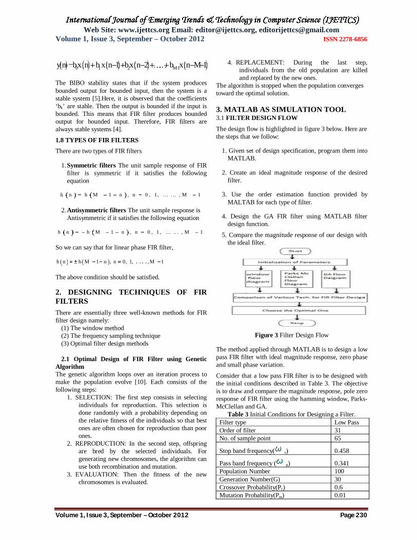
The design flow is highlighted in figure 3 below. Here are the steps that we follow:
1. Given set of design specification, program them into MATLAB.
2. Create an ideal magnitude response of the desired filter.
3. Use the order estimation function provided by MALTAB for each type of filter.
4. Design the GA FIR filter using MATLAB filter design function.
5. Compare the magnitude response of our design with the ideal filter.
Figure 3 Filter Design Flow
The method applied through MATLAB is to design a low pass FIR filter with ideal magnitude response, zero phase and small phase variation.
Consider that a low pass FIR filter is to be designed with the initial conditions described in Table 3. The objective is to draw and compare the magnitude response, pole zero response of FIR filter using the hamming window, Parks-McClellan and GA.
Table 3 Initial Conditions for Designing a Filter. Filter type Low Pass Order of filter 31 No. of sample point 65
Stop band frequency( s) 0.458
Pass band frequency ( p) 0.341 Population Number 100 Generation Number(G) 30 Crossover Probability(Pc) 0.6 Mutation Probability(Pm) 0.01

Web Site: www.ijettcs.org Email: [email protected], [email protected] Volume 1, Issue 3, September – October 2012 ISSN 2278-6856
Volume 1, Issue 3, September – October 2012 Page 231
Ideal Low pass filter passes all the signals that are below the cut off frequency and stop all others. Figure 4 shows that there is flat pass band below pass band frequency
( p = 0.341) and Flat attenuation band above stop band
frequency( s=0.4580).
Figure 4 Magnitude Response
4. SIMULATION RESULTS FOR GENETIC ALGORITHM
Table 4 Filter Coefficients of GA
Magnitude Response GA is an optimizing method to design an FIR filter. Figure 5 shows that its magnitude response is approximately same as ideal response. But it has small amount of ripples in the pass band and very small in stop band. The transition bandwidth is near to optimal method.
Figure 5 GA Magnitude Responses
Phase Response Phase response of FIR filter designing by GA approaches towards zero. Hence there is very small phase change.
Figure 6 Phase Response
5. COMPARISONS OF BLACKMAN WINDOW, PARKS MCCLELLAN AND GA TECHNIQUES FOR FILTER DESIGNING In ideal case there should be flat pass band, flat stop band and a very small transition band width. Fig 7 shows that in case of
1.) Blackman Window: there is a flat pass band, large ripples in stop band and transition band width is very large.
2.) Parks McClellan: there are small ripples in pass band, very large ripples in stop band and transition band width is very small.
3.) Genetic Algorithm: there are small ripples in pass band, very small ripples in stop band and transition band width is very small.
Hence GA has relatively better Magnitude response in comparison to Blackman Window and Parks McClellan
TECHNIQUES
Figure 7 Magnitude Comparison
Phase Response Phase response is the relationship between the phase of a sinusoidal input and the output signal passing through any device that accepts input and produces an output signal, such as filter. Figure 8 shows that phase response of GA as it approaches towards the zeros. Hence phase response of GA is much better in comparison with other two techniques.
Figure 8 Comparisons between Phase Responses

Web Site: www.ijettcs.org Email: [email protected], [email protected] Volume 1, Issue 3, September – October 2012 ISSN 2278-6856
Volume 1, Issue 3, September – October 2012 Page 232
6. SUMMARY In this present work, FIR filter is designed using GA and its comparison is done with Blackman and Parks McClellan in MATLAB. The comparisons are done to improve the magnitude response, phase variation and phase delay. The response is studied by keeping values of fixed order, crossover probability and mutation probability. Out of all three techniques GA offers a quick, simple and automatic method of designing low pass FIR filters that are very close to optimum in terms of magnitude response, frequency response and in terms of phase variation. FIR filter design using Blackman window provide good magnitude response but transition bandwidth is very high, large phase deviation and lack of
control of critical frequencies p and s. To overcome this problem, Parks McClellan is used. But as the order of the filter increases, this method is not suitable. Therefore, to solve all these problems, GA is used. With the help of GA, the number of operations in design process is reduced and coefficient calculation is easily realized.
7. FUTURE WORK The work has been restricted to low pass filters, it
could be extended to high pass, band pass and band stop filters.
Some zeros are lying outside the unit circles. Therefore there is small phase variation. In future work they can lie inside the circle.
REFERENCES [1] Rabiner Lawrence R., “Techniques for Designing
Finite-Duration Impulse-Response Digital Filters”, IEEE Transactions on Communication Technology, Vol. com -19, April 1971
[2] McClellan James H. and Thomas W. Parks, “A Unified Approach to the Design of Optimum FIR Linear-Phase Digital Filters”, IEEE proceeding-circuit theory, Vol. 20, pp. 697 – 701, Nov 1973.
[3] L. R. Rabiner, M.T. Dolan and J.F. Kaiser, “Some Comparisons between FIR and IIR Digital Filters”, Vol- 53, Feb.1973.
[4] Selesnick Ivan W. and C. Sidney Burrus, “Some Exchange Algorithms Complementing the Parks-McClellan Program for Filter Design”, Oct 1995.
[5] Rabiner L.R., Mcclellan J.H., Parks T.W, “FIR Digital Filter Design Techniques using Weighted Chebyshev Approximation”, Proceedings of the IEEE, Vol. 63, pp. 595-610, 1975
[6] Speake T.C. and R.M. Mersereau, “A Comparison of Different Window Formulations for Two-Dimensional FIR Filter Design”, IEEE proceeding Acoustics, Speech, and Signal Processing, Vol. 4, pp. 5-8, Apr 1979.
[7] Rabiner L.R. and B. Gold, “Theory and Application of Digital Signal Processing”, Prentice-Hall, Englewood Cliffs, NJ, 1975.
[8] Jones Douglas L., “Parks-McClellan FIR Filter Design”, pp. 1-9, Feb 2007.
[9] Kaya Turgay and Melih Cevdet Ince, “The FIR filter Design by Using Window Parameters Calculated with GA”, IEEE proceeding- soft computing, pp. 1-4, Sept 2009
[10] Ajoy Kumar Dey, “A Method of Genetic Algorithm (GA) for FIR Filter Construction”, Vol. 1, pp. 87-90, Dec 2010.
[11] Kaur Gurleen and Ranjit Kaur, “The Design of Recursive Digital Filters Using Multiobjective Genetic Algorithm”, Vol. 3, pp 5614-5621, July 2011.
[12] McClellan and Parks, “A Personal History of the Parks-McClellan Algorithm”, IEEE Proceeding- Signal Processing, Vol. 22, pp. 82-86, March 2005
Pardeep Kaur received the B.Tech degree in Electronics and Communication engineering from Institute of Engineering and Technology, Bhaddal in 2008 and Pursuing M.tech in Electronics and Communication engineering From BBSBEC, Fatehgarh Sahib, Punjab. She has a
teaching experience of 3 years and 6 months. She is presently working as a Lecturer in Electronics & Instrumentation Engineering Department, Doaba Group of Colleges, Kharar (Mohali, Punjab).
Simarpreet Kaur has received her M-Tech and B-Tech degrees from Punjab Technical University, India in 2008 and 2001, respectively. She worked as a lecturer in Punjab Engineering College, Chandigarh, India for several years. She is currently working as an Assistant Professor
in Baba Banda Singh Bahadur Engineering College, Fatehgarh Sahib, Punjab. She is guiding many M-Tech thesis. Her research interests are in the fields of broadband communications, QOS and resource management of IP based wireless networks, performance analysis of 3G and 4G networks, wireless sensor networks and Labview.