vaclav zabransky1* petr vavruska - · pdf filecorrection of relative feed-rate during...
TRANSCRIPT

Journal of Machine Engineering, Vol. 16, No. 1, 2016
Received: 22 January 2016 / Accepted: 03 February 2016 / Published online: 10 March 2016
CNC, postprocessor, feed-rate,
optimization
Vaclav ZABRANSKY1*
Petr VAVRUSKA1
PRODUCTIVE MACHINING OF COMPLEX SHAPE PARTS
This paper deals with technological conditions that are achieved during multi-axis milling operations. The work
is focused on the improvement of quality and productivity of machining of complex shape parts. The importance
of feed-rate analysis during multi-axis machining operations is mentioned. A postprocessor algorithm for
correction of relative feed-rate during multi-axis machining operations has been proposed. The postprocessor
generates corrected feed-rate for each block of an NC program when a multi-axis interpolation is found. Thanks
to this new postprocessor algorithm, better conditions are achieved during multi-axis machining operations and
also a shorter time for NC program execution when it is used without the Tool Center Point transformation.
Practical benefits and the functionality of the postprocessor algorithm have been tested by machining the blade
containing multi-axis tool paths.
1. INTRODUCTION
NC program creation is a complex process. An NC program should reflect the
experience of its creator – the production engineer. Nowadays it is possible to produce
almost any shape of the product by five-axis CNC machine tools and it is necessary to use
CAM software for generating CL data (cutter location data) for these complex-shaped parts.
The translation of CL data to an NC code that can be processed by a real machine tool is
done by the compiler called postprocessor. This compiler affects the form of the generated
toolpath and also generates various technological functions. The postprocessor can be
programmed to generate various improvements and features that are activated based on the
settings in the CAM system or CL data. The production engineer should know if there are
some cases in which the CAM system used can generate a toolpath that can have a bad
influence on the tool movement. The manner in which the toolpath is prepared has
an influence on the machine tool behaviour. The machine tool behaviour has an influence on
the machining time and the quality of the machined part. In practice there is often very little
time for order processing and hence it is not possible to try new approaches. Therefore, we
can find the use of spline interpolations mainly at the academic level, where only the
____________ 1 Czech Technical University in Prague, Faculty of Mechanical Engineering, Department of Production Machines and
Equipment, Prague, Czech Republic * E-mail: [email protected]

80 Vaclav ZABRANSKY, Petr VAVRUSKA
mathematical apparatus is analysed mostly, e.g. in the literature [10],[7] and [8].
The application of multi-axis spline interpolation in one CAM system can be found in the
literature [5].
In the past, many attempts were made to optimize the feed-rate. The vast majority
of solutions focused on generating the feed-rate with respect to the cutting depth
(or currently removed volume of material). Different algorithms are used in calculating the
feed-rate and mathematical models of cutting tools are also adjusted to their continuous
optimal cutting geometry development. This issue is the subject of the following texts in the
literature[1],[2],[3],[6]. The principles on which the calculation method for calculating
the feed-rate is based can be found in these papers, but none of them deals with the actual
machine tool control system and rotary axes configuration of machine tools used for
machining.
Therefore, this paper deals with the possibilities of increasing productivity
of machining of complex shaped parts by influencing cutting conditions in the NC code
done by the postprocessor. Tests were performed on the machine SP430 1100 SY 2 and
partly on the machine Multicut 630, both from the production of Kovosvit MAS and both
with the control system Sinumerik 840D sl. CAM software used for creating the toolpath
was NX 9.
2. POSTPROCESOR WITH THE FEED-RATE CONVERSION
Machining of geometrically complex parts is often confronted with the requirement for
non-constant cutting conditions. It means affecting the feed-rate or spindle speed during the
cut so that constant cutting speed is achieved at the point of contact with the workpiece or so
that spindle load is constant. Setting up the feed-rate regulation using CAM software seems
to be the most appropriate solution. Many CAD/CAM systems are able to compute
optimized toolpath for roughing operations. In the case of SurfCAM production engineers
can use the function TrueMill to create the toolpath that are optimized to keep constant
wrapping of the tool so the tool can move with higher velocities. If they should use e.g. the
MasterCAM or the HSMworks, they are able to apply adaptive toolpath. Adaptive toolpath
are alternative functions to the TrueMill but the calculation uses other principles. There are
also various simulation systems that can verify the NC program and even offer the
possibility of automatic NC code modification, for example the Vericut system from
CGTech [12], which provides the OptiPath function OptiPath, which modifies the feed rate
along the toolpath (Fig. 1). If we use this function, the feed-rate in NC program is adjusted
to the current machined material volume in each tool step. This optimization is based on the
volume of current material removal. Other systems with a similar function are WorkNC
from Sescoi [14] or NCsimul from Spring [13]. However, none of CAD/CAM systems is
able to adjust the feed-rate during multi-axis machining owing to the current position of the
tool against rotary axes. This optimization can be achieved by the postprocessor.
The postprocessor with the possibility of machining productivity improvement is dealt
with most in [9]. The possibility is mentioned that the feed-rate correction algorithm for
four and five-axis milling is applicable if the control system function Tool Center Point

Productive Machining of Complex Shape Parts 81
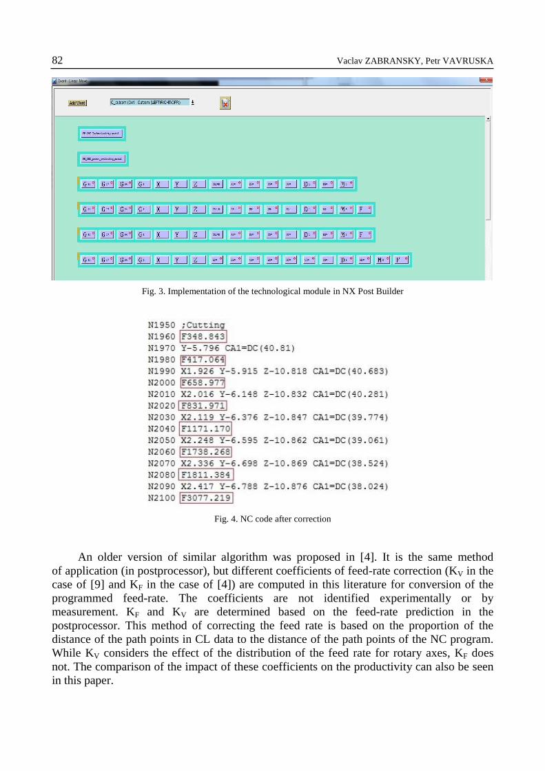
(TCP) is not in use. The algorithm was implemented in a postprocessor (Fig. 2 and Fig. 3)
and the generated NC code contains the feed-rate correction (Fig. 4), which can be seen in
in the red frames.
Fig. 1. OptiPath function
Fig. 1: Schematic location of technological module in postprocessor
Fig. 2. Schematic location of technological module postprocessor
82 Vaclav ZABRANSKY, Petr VAVRUSKA
Fig. 3. Implementation of the technological module in NX Post Builder
Fig. 4. NC code after correction
An older version of similar algorithm was proposed in [4]. It is the same method
of application (in postprocessor), but different coefficients of feed-rate correction (KV in the
case of [9] and KF in the case of [4]) are computed in this literature for conversion of the
programmed feed-rate. The coefficients are not identified experimentally or by
measurement. KF and KV are determined based on the feed-rate prediction in the
postprocessor. This method of correcting the feed rate is based on the proportion of the
distance of the path points in CL data to the distance of the path points of the NC program.
While KV considers the effect of the distribution of the feed rate for rotary axes, KF does
not. The comparison of the impact of these coefficients on the productivity can also be seen
in this paper.

Productive Machining of Complex Shape Parts 83
3. MACHINING OF THE BLADE
The blade used for testing can be seen in Fig. 5, where the toolpath of machining
the blade can be seen. The tool used for finishing (spherical mill) is parallel to the surface
of the blade normal. This is only a testing operation. The final operation is based on the use
of the leading angle.
Fig. 1: Testing toolpath on the blade surface
Fig. 5. Testing toolpath on the blade surface
The correction coefficients of feed-rate generated by the postprocessor during the
machining of this toolpath are shown in Fig. 6. For clarity, the block numbers where the
corrected displacements were generated were placed on the X-axis. Areas with the greatest
displacement corrections can be identified in the CIMCO environment. In this case, they
were to be found on the edge of the blade where it is necessary to drive around a small
radius (trailing edge), see Fig. 6.
Fig. 6. Graph of the correction coefficient KV according to the block of the NC program

84 Vaclav ZABRANSKY, Petr VAVRUSKA
Therefore, an improvement was made to this technological module. Another condition
was introduced to the model, the condition being that the correction coefficient in the next
block should not be greater than a specified limit. The principle of this filter is to set the
maximum correction coefficient step. It is written in the technological module that
the correction coefficient in the next block of the NC program must not be greater than the
previous + proportional constant. If so, the following corrected coefficient is set to
the previous correction coefficient + proportional coefficient. For example Fig. 7 shows
the result when the proportional coefficient is set at 200. This value was set because
of filtering of an unwanted large step in block 4200 (Fig. 6). The lower the value, the
smaller jumps will be filtered. The value of proportional coefficient is set by the user of the
CAM software. Fig. 7 shows two areas with an appreciably greater correction coefficient.
These can be seen in the areas around the leading and trailing edges of the blade. The higher
correction coefficient is a consequence of the large curvature of the surfaces.
Fig. 7. Comparison of not smoothed (KV) and smoothed (KZ) feed-rate correction coefficient depending
on the number of block of the NC program
In this case the large step of programmed feed-rate occurs within one NC block.
Although it is required by the technology, we work with real machines and drives so that
a step of such magnitude is not desirable in terms of fluency and cutting compliance with
good quality and the quality of the workpiece surface. That it actually is not such a great
step of feed-rate may be greatly influenced by the Look Ahead function, which could
smooth out the step to some extent. Look Ahead might not always be switched on.
Therefore it is better for large steps which would rather deteriorate than increase machining
productivity, to be partially smoothed by the postprocessor.

Productive Machining of Complex Shape Parts 85
The size of the of the correction coefficient step was set in the technological
postprocessor module. The result of this extension is shown in Fig. 7. It can be seen that the
large steps were filtered by new coefficients KZ, computed using an improved algorithm.
These corrections were now prepared for real machining of the blade on the four axis
machine tool MAS SP 430 SY 2 1100.
4. THE TOOLPATH ERRORS AND THE CHOICE OF FINISHING STRATEGIES
Continuous machining around the leading edge was not considered because of the
complexity of blade geometry, which is shown in Fig. 5. Multi-axis milling around the
small radius on the edges leads to considerable unproductivity when the TCP function or
correction of feed-rate is not used. This unproductivity is seen in Fig. 6, where the feed-rate
correction coefficient around the edge of the blade reaches approximately the value
of 12 000 [-]. This means that if the function TCP is not active, the feed-rate would be very
small, and certainly the technology conditions are not respected. This is one of the reasons
why it is necessary to think about the setting of finishing operations. Another reason for the
setting of finishing operation was that the NX CAM system has a problem with generating
toolpath. It is recommended to use the Streamline function for manufacturing complex
shapes. There is an advantage in the possibility of scalloping any shape of workpiece by
Streamline. The issue with the streamline setup is a different control surface and surface to
be machined. Streamline creates a surface on which the grid is given by the chosen criterion,
as the above-mentioned scallop or boundary of machining. This grid is then projected onto
the surface to be machined. However, there may be errors and issues in this projection.
There are significant errors in the finishing toolpath if we look closer at the part in Fig. 8
Toolpath is green and the errors are in the red rectangles.
There are noticeable jerking movements of the cutter on the edge of the blade.
The cutter even performs a jerking movement backwards and forwards. Toolpath errors can
be seen in Fig. 8. They are more evident when setting stricter CAM tolerance. In this case
the tolerance is set to the value of ± 0.001 mm. The surface is undercut in the size of tenth
of millimetres as shown in Fig. 9. Toolpath errors on the edges of the blades were removed
by finishing the edges separately in three axes.
Finishing of the suction and pressure sides (Fig. 10 and Fig. 11) is a four-axis
operation, when the mill D4 R1.5 is led with an angle of 10° to the workpiece surface.
Toolpath errors in Fig. 8, as well as consequences in Fig. 9, were removed by the
adjustment of CAM tolerance. CAM tolerance was set to +0.018 mm (Fig. 12) by sequential
testing and then the least toolpath errors have been achieved. Compared to the usual
tolerance of the blade (+0.1 mm), the CAM tolerance is assessed as sufficient. It is even five
times stricter. All CAM errors could not be removed completely (Fig. 13), and therefore are
only minimized.
The blade machining was made on a SP 430 SY 2 1100 machine from the production
of Kovosvit MAS. The machine stands in the laboratories of the Czech Technical University
in Prague. NC codes were generated by an improved postprocessor. A test was run

86 Vaclav ZABRANSKY, Petr VAVRUSKA
concerning the influence of the control system setting on the final quality of the blade
surface and machining productivity on this machine.
Fig. 8. Toolpath errors (marked by red rectangles)
Fig. 9. Consequences of toolpath errors
Fig. 10. Suction side finishing Fig. 11. Pressure side finishing
Fig. 12. CAM tolerance setting Fig. 13. Toolpath errors (marked by red rectangle)

Productive Machining of Complex Shape Parts 87
The test was designed in the following manner. For the same finishing toolpath, an NC
code was generated by the postprocessor as follows:
1. Finishing with active TCP;
2. Finishing without TCP;
3. Finishing without TCP with active technological module - KV correction (resp. KZ);
4. Finishing without TCP with active technological module – KF correction.
5. THE TEST OF CHOSEN STRATEGIES PRODUCTIVITY
For verification and mutual comparison, it would be advisable to perform this test on
two different machines by the same producer: SP430 and Multicut 630. It was not possible
to carry out these four tests on Multicut 630 because of its busy timetable in production.
Table 1. Testing on the SP430 SY2 1100 machine tool
Test Side Time [min:s]
1) With TCP
Suction side 37:49
Pressure side 32:53
2) Without TCP
Suction side 34:41
Pressure side 33:16
3) Without TCP, KV
Suction side 33:15
Pressure side 25:43
4) Without TCP, KF
Suction side 38:55
Pressure side 32:23
Table 2. Testing on the Multicut 630 machine tool
Test Side Time [min:s]
With TCP
Suction side 39:29
Pressure side 37:27
According to the results listed in Table 1, it can be concluded that the most productive
strategy was the one without TCP and with KV feed-rate correction. Very similar results are
achieved by using TCP and without TCP - with KF feed-rate correction. It is an interesting
finding that the switching off of the TCP function can sometimes bring higher productivity
than active TCP, as was the case with the suction side of the blade. The surface quality is
evaluated in the following section.
88 Vaclav ZABRANSKY, Petr VAVRUSKA
6. THE SURFACE QUALITY
The equipment Subtronik 3+ was used for measurements which can determine what
surface quality has been achieved for milling. The surface was measured in a direction
perpendicular to the line of flow and also in the direction of flow. We can assess sufficient
”scallop”, a parameter influencing the number of passes of the tool, according to the surface
perpendicular to the direction of streamlines.
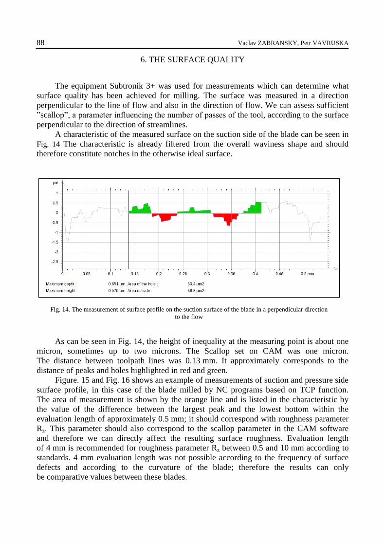
A characteristic of the measured surface on the suction side of the blade can be seen in
Fig. 14 The characteristic is already filtered from the overall waviness shape and should
therefore constitute notches in the otherwise ideal surface.
Fig. 14. The measurement of surface profile on the suction surface of the blade in a perpendicular direction
to the flow
As can be seen in Fig. 14, the height of inequality at the measuring point is about one
micron, sometimes up to two microns. The Scallop set on CAM was one micron.
The distance between toolpath lines was 0.13 mm. It approximately corresponds to the
distance of peaks and holes highlighted in red and green.
Figure. 15 and Fig. 16 shows an example of measurements of suction and pressure side
surface profile, in this case of the blade milled by NC programs based on TCP function.
The area of measurement is shown by the orange line and is listed in the characteristic by
the value of the difference between the largest peak and the lowest bottom within the
evaluation length of approximately 0.5 mm; it should correspond with roughness parameter
Rz. This parameter should also correspond to the scallop parameter in the CAM software
and therefore we can directly affect the resulting surface roughness. Evaluation length
of 4 mm is recommended for roughness parameter Rz between 0.5 and 10 mm according to
standards. 4 mm evaluation length was not possible according to the frequency of surface
defects and according to the curvature of the blade; therefore the results can only
be comparative values between these blades.

Productive Machining of Complex Shape Parts 89
The evaluated surface is always in the place where there are no surface defects.
Surface defects, according to standards CSN EN ISO 4287, are not counted into the surface
roughness, but play an important role, therefore they are also evaluated. All results are listed
in Table 3, which also shows the evaluation of surface defects. The smallest evaluation
number shows the result with the least defects, while the highest number indicates a surface
with numerous defects.
Table 3. Comparison of achieved surface quality
Blade Rz value [µm] Evaluation of surface defects [-]
Suction side Pressure side Suction side Pressure side
1) With TCP 3,4 3,3 3 3
2) Without TCP 1,4 2,4 5 3
3) Without TCP, KV 3 2,1 5 5
4) Without TCP, KF 3,1 4 3 3
5) With TCP – Multicut 630 1,8 1,6 2 2
Regarding the surface quality, the best results are achieved when using TCP.
The blade machined by TCP comprises less visible defects compared to the others. A very
similar surface of the blade was machined without TCP with KF feed-rate correction, with
comparable productivity. It can be seen that by using KV coefficient, productive operations
as well as suitable roughness can be achieved.
Fig. 15. The example of surface measurement of suction side of the blade milled by NC programs based
on TCP function
Fig. 16. The example of surface profile measurement of pressure side of the blade milled by NC programs based
on TCP function

90 Vaclav ZABRANSKY, Petr VAVRUSKA
Surface differences are also visible between the blade machined on the machine tool
SP430 and Multicut 630. The blade from Multicut 630 has fewer surface defects and
roughness values Rz are approximately twice as good as the blade from SP430.
7. CONCLUSION
The findings mentioned in this paper can be interpreted as possibilities how cutting
conditions as well as productivity can be influenced by suitable adjustment in the
postprocessor. A proposal was made to extend the existing technological module to include
filtering of large steps in feed-rate. Simultaneously, the real influence of a variously
modified NC code on the productivity of blade finishing operations and surface quality was
tested. It can also be seen that linking simulation models in the CAM system with
a postprocessor has potential for future increasing of machining productivity. This paper
shows that even CAM software is not an omnipotent tool for creating toolpath and should
be used cautiously. The achieved results point to the fact that the TCP function can be well
substituted by the proposed correction function of the postprocessor, but the results do not
fully answer the question when it is better to use the control system function TCP and when
the proposed correction. The results clearly show that by using the proposed postprocessor
function for feed-rate correction the productivity of machining is higher than in the case
without TCP and also in some case with TCP. The results also indicate that the same
productivity and surface quality can be achieved by using TCP, even without TCP using the
appropriate corrections, as in the case of blades 4) in Table 3.
ACKNOWLEDGMENTS
This paper has received funding from the Technology Agency of the Czech Republic.
REFERENCES
[1] BAEK D.K., KO T.J., 2008, Feedrate scheduling for free-form surface using an NC verification model, In
International Journal of Machine Tools & Manufacture, 48/2, 163-172.
[2] FENG H.Y., SU N., 2005, Integrated tool path and feed rate optimization for the finishing machining of 3D plane
surfaces, In International Journal of Machine Tools & Manufacture, 40/11, Amsterdam, Elsevier, 1557-1572.
[3] FERRY W.B.S., 2008, Virtual five-axis flank milling of jet engine impellers, Vancouver, A thesis submitted in
partial fulfillment of the requirements for the degree of doctor of philosophy, The University of British Columbia.
[4] FORNŮSEK T., RYBÍN J., 2008, Optimalization of NC code. In Proceedings of International Congress MATAR
PRAHA 2008, ISBN 978–80–904077–0–1, Praha, 137-141.
[5] LANGERON J.M. et al., 2004, A new format for 5-axis tool path computation, using Bspline curves, Computer-
Aided Design, September, 36/12, 1219-1229.
[6] LEE H. U., CHO D.W., 2003, An intelligent feedrate scheduling based on virtual machining, In The International
Journal of Advanced Manufacturing Technology, 22/11-12, 873-882.
[7] MÜLLER M. et al., 2004, High accuracy spline interpolation for 5-axis machining, Computer-Aided Design,
November, 36/13, 1379-1393.

Productive Machining of Complex Shape Parts 91
[8] PATELOUP V. et al., 2010, Bspline approximation of circle arc and straight line for pocket machining,
Computer-Aided Design, September, 42/9, 817-827.
[9] VAVRUŠKA P., 2013, Technological extensions of postprocessors for multi-axis machine tools, Praha, A thesis
submitted in partial fulfillment of the requirements for the degree of doctor of philosophy, CTU in Prague, Faculty
of Mechanical Engineering.
[10] WANG F.C., YANG D.C.H., 1993, Nearly arc-length parametrized quintic-spline interpolation for precision
machining, Computer-Aided Design, May, 25/5, 281-288.
[11] https://support.industry.siemens.com
[12] http://www.cgtech.com/
[13] http://www.ncsimul.com/
[14] http://www.worknc.com/