upqc for improvement power quality. - ijei: hard copy of ... september 2014/eee4 04040719/eee… ·...
TRANSCRIPT

International Journal of Engineering Inventions
e-ISSN: 2278-7461, p-ISSN: 2319-6491
Volume 4, Issue 4 [Sep 2014] PP: 07-19
www.ijeijournal.com Page | 7
UPQC for Improvement Power Quality.
Dr.S Kamakshaiah1
Ashwini Kumar2
1,2,
Dept of EEE, SreeDattha Institute of Engineering and Science
ABSTRACT: This proposed new concept of optimal utilization of a unified power quality conditioner (UPQC)
with a power angle control approach is illustrated. The active power control approach is used to compensate voltage sag/swell and is integrated with theory of power angle control (PAC) of UPQC to coordinate the load reactive power between the two inverters. The series inverter of UPQC is controlled to perform simultaneous 1) voltage sag/swell compensation and 2) load reactive power sharing with the shunt inverter. Since the series
inverter simultaneously delivers active and reactive powers, this concept is named as UPQC-S (S for complex power). A detailed mathematical analysis, to extend the PAC approach for UPQC-S, is presented in this paper. MATLAB/SIMULINK-based simulation results are discussed to support the developed concept.
Key Words: UPFC,PAC,UPQC,UPQC-S
I. 1.INTRODUCTION
The modern power distribution system is becoming highly vulnerable to the different power quality problems. The extensive use of nonlinear loads is further contributing to increased current and voltage harmonics issues.
Furthermore, the penetration level of small/large-scale renewable energy systems based on wind energy, solar
energy, fuel cell, etc., installed at distribution as well as transmission levels is increasing significantly. This integration of renewable energy sources in a power system is further imposing new challenges to the electrical
power industry to accommodate these newly emerging distributed generation systems. To maintain the controlled power quality regulations,somekind of compensation at all the power levels is becoming a common
practice. At the distribution level, UPQC is a most attractive solution to compensate several major power quality
problems. The general block diagram representation of a UPQC-based system is shown in Fig. 1. It basically consists of two voltage source inverters connected back to back using a common dc bus capacitor. This paper
deals with a novel concept of optimal utilization of a UPQC.
/
Fig.1. Unified power quality conditioner (UPQC) system configuration. The voltage sag/swell on the system is one of the most important power quality problems. The voltage sag/swell
can be effectively compensated using a dynamic voltage restorer, series active filter, UPQC, etc.. Among the
available power quality enhancement devices, the UPQC has better sag/swell compensation capability. Three
significant control approaches for UPQC can be found to control the sag on the system: 1) active power control
approach in which an in-phase voltage is injected through series inverter, popularly known as UPQC-P; 2)
reactive power control approach in which a quadrature voltage is injected [23], [24], known as UPQC-Q; and 3)
a minimum VA loading approach in which a series voltage is injected at a certain angle, in this paper called as
UPQC-VAmin. In a minimum VA loading approach, the series inverter voltage is injected at an optimal angle
with respect to the source current. Besides the series inverter injection, the current drawn by the shunt inverter,
to maintain the dc link voltage and the overall power balance in the network, plays an important role in
determining the overall UPQC VA loading.The reported paper on UPQC-VAmin is concentrated on the optimal
UPQC for Improvement Power Quality.
www.ijeijournal.com Page | 8
VA load of the series inverter of UPQC especially during voltage sag condition. The PAC concept suggests that
with proper control of series inverter voltage the series inverter successfully supports part of the load reactive
power demand, and thus reduces the required VA rating of the shunt inverter. The PAC of UPQC concept
determines the series injection angle by estimating the power angle δ.Similar to PAC of UPQC, the reactive
power flow control utilizing shunt and series inverters is also done in a unified power flow controller (UPFC). A
UPFC is utilized in a power transmission system whereas a UPQC is employed in a power distribution system to
perform the shunt and series compensation simultaneously. The primary objective of a UPFC is to control the
flow of power at fundamental frequency. In this paper, the concept of PAC of UPQC is further expanded for
voltage sag and swells conditions. This modified approach is utilized to compensate voltage sag/swell while sharing the load reactive power between two inverters. Since the series inverter of UPQC in this case delivers both active and reactive powers, it is given the name UPQCS (S for complex power.) A. Proposed Project 1) The series inverter of UPQC-S is utilized for simultaneous voltage sag/swell compensation and load
reactive power compensation in coordination with shunt inverter. 2) In UPQC-S, the available VA loading is utilized to its maximum capacity during all the working conditions
contrary to UPQC-VAmin where prime focus is to minimize the VA loading of UPQC during voltage sag condition.
3) The concept of UPQC-S covers voltage sag as well as swell scenario. In this paper, a detailed mathematical formulation of PAC for UPQC-S is carried out. The feasibility and effectiveness of the proposed UPQC-S approach are validated by simulation as well as experimental results.
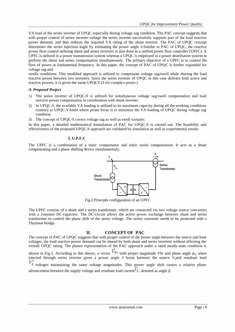
2. U.P.F.C The UPFC is a combination of a static compensator and static series compensation. It acts as a shunt compensating and a phase shifting device simultaneously.
Fig.2.Principle configuration of an UPFC
The UPFC consists of a shunt and a series transformer, which are connected via two voltage source converters with a common DC-capacitor. The DC-circuit allows the active power exchange between shunt and series transformer to control the phase shift of the series voltage. The series converter needs to be protected with a Thyristor bridge.
II. CONCEPT OF PAC The concept of PAC of UPQC suggests that with proper control of the power angle between the source and load voltages, the load reactive power demand can be shared by both shunt and series inverters without affecting the overall UPQC rating. The phasor representation of the PAC approach under a rated steady-state condition is
shown in Fig.3. According to this theory, a vector with proper magnitude VSr and phase angle ϕSr when injected through series inverter gives a power angle δ boost between the source VSand resultant load
voltages maintaining the same voltage magnitudes. This power angle shift causes a relative phase
advancement between the supply voltage and resultant load current , denoted as angle β.

UPQC for Improvement Power Quality.
www.ijeijournal.com Page | 9
For a rated steady-state condition
|VS | = |VL | = |V∗L | = |V’L | = k (1)
Using Fig. 3, phasor _VSr can be defined as
(2)
Where
(3)
Fig.3. Concept of PAC of UPQC
A. Voltage SAG/SWELL Compensation Utilizing UPQC-Pand UPQC-Q
Fig. 4 Voltage sag and swell compensation using UPQC-P and UPQC-Q: phasor representation. (a) Voltage Sag (UPQC-P). (b) Voltage Sag (UPQC-Q). (c) Voltage Swell (UPQC-P). (d) Voltage Swell (UPQC-Q).

UPQC for Improvement Power Quality.
www.ijeijournal.com Page | 10
The voltage sag on a system can be compensated through active power control and reactive power control methods. Fig.4 shows the phasor representations for voltage sag compensation using active power control as in UPQC-P [see Fig. 4(a)] and reactive power control as in UPQC-Q [see Fig. 4(b)]. Fig. 4(c) and (d) shows the compensation
capability of UPQC-P and UPQC-Q to compensate a swell on the system. For a voltage swell compensation using UPQC-Q [see Fig. d(d)], the quadrature component injected by series inverter does not intersect with the rated voltage locus. Thus, the UPQC-Q approach is limited to compensate the sag on the system.
B. PAC Approach Under Voltage SAG Condition Consider that the UPQC system is already working under PAC approach, i.e., both the inverters are compensating the load reactive power and the injected series voltage gives a power angle δ between resultant load and the actual source voltages. If a sag/swell condition occurs on the system, both the inverters should keep supplying the load reactive power, as they were before the sag.
Fig.5 Phasor representation of the proposed UPQC-S approach under voltage sag condition.
Let us represent a vector responsible to compensate the load reactive power utilizing PAC concept and
vector
responsible to compensate the sag on the system using active power control approach. Thus, for
simultaneous compensation, as noticed from Fig.5, the series inverter should now supply a component which
would be the vector
sum of and . This resultant series inverter voltage
will maintain the load voltage magnitude at a desired level such that the drop in source voltage will not
appear across the load terminal.
For load reactive power compensation using PAC concept

UPQC for Improvement Power Quality.
www.ijeijournal.com Page | 11
(4)
(5) For voltage sag compensation using active power control approach
(6)
(7) For simultaneous load reactive power and sag compensation
(8) (i) Series Inverter Parameter Estimation under Voltage Sag In this section, the required series inverter parameters to achieve simultaneous load reactive power and voltage sag compensations are computed. Fig. 6 shows the detailed phasor diagram to determine the magnitude and phase of series injection voltage.
Fig. 6 Detailed phasor diagram to estimate the series inverter parameters for the proposed UPQC-S approach
under voltage sag condition.
The voltage fluctuation factor kf which is defined as the ratio of the difference of instantaneous supply voltage and rated load voltage magnitude to the rated load voltage magnitude is represented as
(
9
)
Representing (9) for sag condition under PAC
(
1
0
)
Let us define
1 + kf = nO (11)
To compute the magnitude
of
, from CHB in Fig. 6
(12)
(13) To compute the phase of
(14)
Therefore,
(15)
Equations (13) and (15) give the required magnitude and phase of series inverter voltage of UPQC-S.
(ii) Shunt Inverter Parameter Estimation Under Voltage
Sag The phasor diagram based on different currents is represented in Fig. 7. The current ISh represents the required

UPQC for Improvement Power Quality.
www.ijeijournal.com Page | 12
current if the shunt inverter is used alone to compensate the total load reactive power demand. Thus, to support the series inverter to inject the required voltage for load reactive power and sag compensations, the shunt inverter should now deliver the current IS__h. Fig. 8 represents the phasor diagram to compute the shunt inverter injected current magnitude and its phase angle.
Fig. 7. Current-based phasor representation of the proposed UPQC-S approach under voltage sag condition.
Fig. 8. Detailed phasor diagram to estimate the shunt inverter parameters To support the active power required during voltage sag condition, the source delivers the extra source current. During voltage sag
on the system using active power control approach. For simultaneous compensation, the series inverter should
supply the component to support the load reactive power and to compensate the swell on the system. The
resultant series injected voltage would maintain the load voltage magnitude at a desired level while
supporting the load reactive power.
Fig 9. Phasor representation of the proposed UPQC-S approach under voltage Swell condition.

UPQC for Improvement Power Quality.
www.ijeijournal.com Page | 13
For voltage swell compensation using active power control approach
(24)
. (16)
L
e
t
(17) Fig. 10. Current-based phasor
representation of the proposed
Therefore, UPQC-S approach
(
1
8
)
Under voltage swell condition.
In GFJ (see Fig. 5.6)
(25)
(
1
9
)
For simultaneous load reactive power and voltage swell
compensations
(
2
0
)
(
2
6
)
For series inverter
(
2
1
)
(
2
7
)
(
2
2
)
(
2
8
)
(
2
3
(
2
9

UPQC for Improvement Power Quality.
www.ijeijournal.com Page | 14
) )
Fig.10shows the phasor representation for
different currents
Equations (20) and (23) give the required magnitude and
under PAC of UPQC-S under a voltage swell condition.
phase angle of a shunt inverter .
C. PAC Approach Under Voltage SWELL
Condition
This reduced shunt inverter current is
represented as .
For shunt inverter (see Fig. 5.8)
The phasor representation for PAC of UPQC-
S during a
voltage swell on the system is shown in
Fig. 9. Let us
(
3
0
)
represent a vector VSr3 responsible to
compensate the swell
31)
(32) It can be noted that the equations for voltage sag and swell compensation utilizing the PAC of UPQC-S are identical. D. ACTIVE–REACTIVE POWER FLOW THROUGH UPQC-S The per-phase active and reactive powers flow through the UPQC-S during the voltage sag/swell is determined in this section.
For active power
From Fig.8 For reactive power
From Fig. 8 (45)
(46)
(47)
(48) (i) Series Inverter of UPQC-S For active power
From Fig. 6

UPQC for Improvement Power Quality.
www.ijeijournal.com Page | 15
(49)
(50) Using (47) and (50), the active and reactive power flow through shunt
inverter of UPQC-S during voltage sag/swell condition can be calculated and utilized to determine the overall
UPQC-S VA loading
(37)
The increase or decrease in the source current magnitudes during the voltage sag or swell condition,
respectively, is represented as
(38) Therefore,
(33)
(iii) UPQC-S CONTROLLER A detailed controller for UPQC based on PAC approach is described. Furthermore, the power angle δ is maintained at constant value under different operating conditions. Therefore, the reactive power shared by the series inverter and hence by the shunt inverter changes as given by (43) and (51). (39) MATLAB CIRCUITS For reactive power
(40) From Fig. 6
(41) (42)
(43) Therefore,
(44) Using (39) and (44), the active and reactive power flow through series
inverter of UPQC-S during voltage sag/swell condition can be calculated. Below figure 12 gives the simulink diagram of proposed method.
(ii) Shunt Inverter of UPQC-S The active and reactive power handled by the shunt inverter as seen from the source side is determined as follows
UPQC for Improvement Power Quality.
www.ijeijournal.com Page | 16
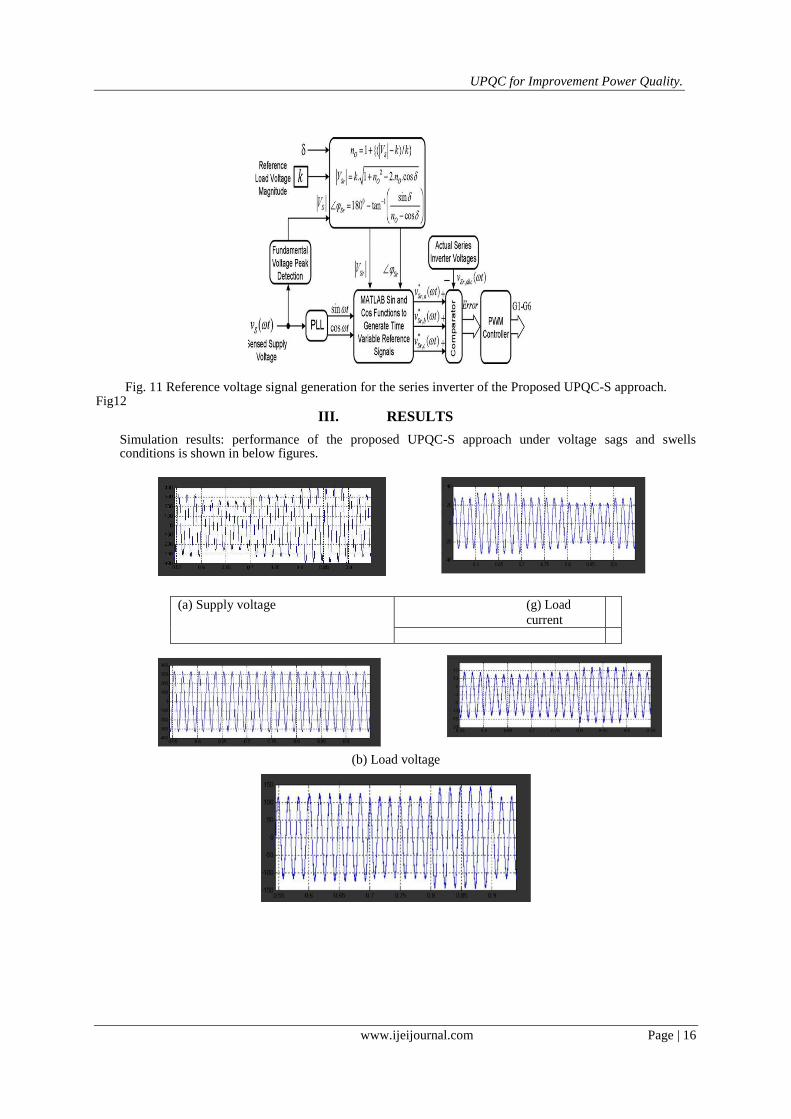
Fig. 11 Reference voltage signal generation for the series inverter of the Proposed UPQC-S approach. Fig12
III. RESULTS
Simulation results: performance of the proposed UPQC-S approach under voltage sags and swells conditions is shown in below figures.
(a) Supply voltage (g) Load
current
(b) Load voltage
UPQC for Improvement Power Quality.
www.ijeijournal.com Page | 17
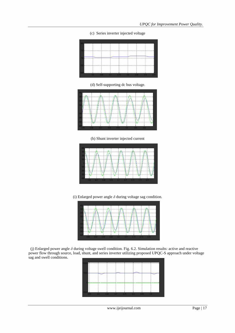
(c) Series inverter injected voltage
(d) Self-supporting dc bus voltage.
(h) Shunt inverter injected current
(i) Enlarged power angle δ during voltage sag condition.
(j) Enlarged power angle δ during voltage swell condition. Fig. 6.2. Simulation results: active and reactive
power flow through source, load, shunt, and series inverter utilizing proposed UPQC-S approach under voltage sag and swell conditions.

UPQC for Improvement Power Quality.
www.ijeijournal.com Page | 18
e) Enlarged power angle δ relation between supply and load voltages during steady-state condition.
(f) Supply current.
(a) Source P and Q
(b) Load P and Q.
(c) Series inverter P and Q.
(d) Shunt inverter P and Q.
IV. CONCLUSION Performance of Voltage sag/swell and load reactive power compensation have been done by UPQC with a PAC
approach.
REFERENCES [1] R. C. Dugan, M. F. McGranaghan, and H. W. Beaty, Electrical Power Systems Quality.. New York:
McGraw-Hill, 1996, p. 265. [2] C. Sankaran, Power Quality. Boca Raton, FL: CRC Press, 2002, p. 202. [3] R. A. Walling, R. Saint, R. C. Dugan, J. Burke, and L. A. Kojovic,
UPQC for Improvement Power Quality.
www.ijeijournal.com Page | 19
―Summary of distributed resources impact on power delivery systems,‖ IEEETrans. Power Del., vol. 23, no. 3, pp. 1636–1644, Jul. 2008.
[4] L. Gyugyi, ―Unified power-flow control concept for flexible AC transmission systems,‖ IEE – C Gene. Trans. Distr., vol. 139, no. 4, pp. 323–331, Jul. 1992.
[5] N. G. Hingorani and L. Gyugyi, Understanding FACTS: Concepts and Technology of Flexible AC Transmission Systems. New York: IEEE Press, 2000, p. 432.
[6] V. K. Sood, HVDC and FACTS Controllers – Applications of Static Convertersin Power Systems. Boston, MA: Kluwer, 2004, p. 295.
[7] A. Ghosh and G. Ledwich, Power Quality Enhancement Using Custom Power Devices. Boston, MA: Kluwer, 2002, p. 460.
[8] B. Singh, K. Al-Haddad, and A. Chandra, ―A review of active power filters for power quality improvement,‖ IEEE Trans. Ind. Electron., vol. 45, no. 5, pp. 960–971, Oct. 1999.
[9] M. El-Habrouk, M. K. Darwish, and P. Mehta, ―Active power filters: A review,‖ IEE Electr. Power Appl., vol. 147, no. 5, pp. 403–413, Sep. 2000.
[10] Doncker, C. Meyer, R. W. De, W. L. Yun, and F. Blaabjerg, ―Optimized control strategy for a medium-voltage DVR— Theoretical investigations and experimental results,‖ IEEE Trans. Power Electron., vol. 23, no. 6, pp. 2746–2754, Nov. 2008.
[11] C. N. Ho and H. S. Chung, ―Implementation and performance evaluation of a fast dynamic control scheme for capacitor-supported interline DVR,‖ IEEE Trans. Power Electron., vol. 25, no. 8, pp. 1975–1988, Aug. 2010.
[12] Y. Chen, C. Lin, J. Chen, and P. Cheng, ―An inrush mitigation technique of load transformers for the series voltage sag compensator,‖ IEEE Trans. Power Electron., vol. 25, no. 8, pp. 2211–2221, Aug. 2010.
[13] S. Subramanian and M. K. Mishra, ―Interphase AC–AC topology for voltage sag supporter,‖ IEEE Trans. Power Electron., vol. 25, no. 2, pp. 514–518, Feb. 2010.
[14] H. Fujita and H. AkagiIEEE Trans. Power Electron., vol. 13, no. 2,
pp. 315–322, Mar. 1998. [15] V. Khadkikar and A. Chandra, ―A new control philosophy for a unified power quality conditioner
(UPQC) to coordinate load-reactive power demand between shunt and series inverters,‖ IEEE Trans. Power Del., vol. 23, no. 4, pp. 2522–2534, Oct. 2008.
[16] M. Vilathgamuwa, Z. H. Zhang, and S. S. Choi, ―Modeling, analysis and control of unified power quality conditioner,‖ in Proc. IEEE Harmon. Quality Power, Oct. 14–18, 1998, pp. 1035–1040.
[17] M. Gon, H. Liu, H. Gu, and D. Xu, ―Active voltage regulator based on novel synchronization method for
unbalance and fluctuation compensation,‖ in Proc. IEEE Ind. Electron. Soc (IECON), Nov. 5– 8,, 2002,
pp. 1374–1379. [18] M. S. Khoor and M. Machmoum, ―Simplified analogical control of a unified power quality conditioner,‖
in Proc. IEEE Power Electron. Spec. Conf. (PESC), Jun., 2005, pp. 2565–2570. [19] V. Khadkikar, A. Chandra, A. O. Barry, and T. D. Nguyen,
―Analysis of power flow in UPQC during voltage sag and swell conditions for selection of device ratings,‖ in Proc. IEEE Electr. Computer Eng. (CCECE), May 2006, pp. 867–872.
[20] B. Han, B. Bae, H. Kim, and S. Baek, ―Combined operation of unified power-quality conditioner with distributed generation,‖ IEEE Trans. Power Del., vol. 21, no. 1, pp. 330–338, Jan. 2006.
[21] H. R. Mohammadi, A. Y. Varjani, and H. Mokhtari, ―Multiconverter unified power-quality conditioning system:MC-UPQC,‖ IEEE Trans. Power Del., vol. 24, no. 3, pp. 1679–1686, Jul. 2009.
[22] I. Axente, J. N. Ganesh, M. Basu, M. F. Conlon, and K. Gaughan, ―A 12-kVA DSP-controlled laboratory prototype UPQC capable of mitigating unbalance in source voltage and load current,‖ IEEE Trans. Power Electron., vol. 25, no. 6, pp. 1471–1479, Jun. 2010.
[23] M. Basu, S. P. Das, and G. K. Dubey, ―Investigation on the performance of UPQC-Q for voltage sag mitigation and power quality improvement at a critical load point,‖ IET Generat., Transmiss.Distrib., vol. 2, no. 3, pp. 414–423, May 2008.
[24] V. Khadkikar and A. Chandra, ―A novel control approach for unified power quality conditioner Q without active power injection for voltage sag compensation,‖ in Proc. IEEE Int. Conf. Ind. Technol. (ICIT), Dec. 15–17, 2006, pp. 779–784.
[25] M. Yun, W. Lee, I. Suh, and D. Hyun, ―A new control scheme of unified power quality compensator-Q with minimum power injection,‖ in Proc. IEEE Ind. Electron. Soc. (IECON), Nov. 2–6,, 2004, pp. 51–56.