design and implementation of upqc to solve power quality ... · design and implementation of upqc...
TRANSCRIPT

International Journal of Engineering and Technical Research (IJETR)
ISSN: 2321-0869, Volume-2, Issue-10, October 2014
109 www.erpublication.org
Abstract— this paper deals with conceptual study of Unified
Power Quality Conditioner (UPQC) during voltage sag and
swell on the power network. Power quality has become an
important factor in power systems, for household appliances
with production of various electric and electronic equipment
and computer systems. The main reasons of a poor power
quality are harmonic currents, reduced power factor, supply
voltage variations etc. The Unified Power Quality Conditioner
(UPQC) is a custom power device, which diminishes voltage and
current related power quality issues. It also prevents load
current harmonics from entering the utility and corrects the
input power factor of the load. The system performance for
current and voltage harmonics, voltage sags and voltage swell
have been evaluated. The results obtained by means of the
MATLAB / SIMULINK based simulations support the
functionality of the UPQC.
Index Terms— UPQC, UPQC Topologies, Voltage Sag,
Voltage Swell, Etc.
I. INTRODUCTION
In today's complex electronics environment, many problems
can occur because of poor quality of power. Therefore, it has
become necessary to provide a dynamic solution with greater
degree of accuracy as well as with fast speed of response.
With great advancement in all areas of engineering, mainly,
digital processing, control systems, and power electronics, the
load characteristics have changed totally. In addition to this,
loads are becoming very sensitive to voltage supplied to them.
The power electronics based devices have been used to
overcome the major power quality problems [1].
There are sets of conventional solutions to the power quality
problems, which have existed for a long time. However these
predictable solutions use passive elements and do not always
respond correctly as the nature of the power system conditions
change. The power electronic based power conditioning
devices can be effectively utilized to improve the quality of
power supplied to customers. One modern solution that deals
with both load current and supply voltage imperfections is the
Unified Power Quality Conditioner (UPQC) [2], which was
first presented in 1995 by Hirofumi Akagi.
UPQC is a combination of series and shunt active filters
connected in cascade via a common dc link capacitor. The
series active filter introduces a voltage, which is added at the
Point of Common Coupling (PCC) such that the load-end
voltage remains unaffected by any voltage disturbance. The
main objectives of shunt active filter are: to compensate the
Manuscript received October 13, 2014. Meenakshi Bhardwaj, Electrical Engineering Dept.,G.G.S College of
Modern Technology, Punjab Technical University, Kharar, India,
Akhil Gupta, Associate Professor, Electrical Engineering Dept., G.G.S
College of Modern Technology, Punjab Technical University, Kharar, India,
load reactive power demand and unbalance, to eliminate
harmonics from the supply current, and to control the
common dc link voltage. It uses a pair of three-phase
controllable bridges to produce current that is injected into a
transmission line using a series transformer. The controller
bridge can control active and reactive power flows in a
transmission line [3].
In case of the UPQC, the DC link voltage requirement for the
shunt and series active filters is not the same; the shunt active
filter requires higher DC link voltage when compared to the
series active filter for proper compensation. The shunt active
filter provides a path for real power flow to aid the operation
of the series compensator and to maintain constant average
voltage across the DC storage capacitor. With the high value
of DC link capacitor, the Voltage Source Inverters (VSI)
becomes bulky and the switches used in the VSI also need to
be rated for higher value of voltage and current. This
increases the entire cost and size of the VSI [20].
In literature, a hybrid filter has been discussed for motor
drive applications. This filter is connected in parallel with
diode rectifier and tuned at 5th
harmonic frequency. In simpler
words, Power quality is a set of electrical boundaries that
allow a piece of equipment to function in its intended manner
without significant loss of performance. Although a
sophisticated work, the design is specific to the motor drive
application and the reactive power compensation is not
considered, which is an important aspect in shunt active filter
applications [4].
The paper is organized as follows. The structure of the
UPQC is presented in Section II. In Section III, the
configuration of UPQC is described in detail. The all
simulation results are presented in Section IV. Simulation
results in this section demonstrate the efficacy and versatility
of proposed design technique. Finally, Section V gives the
conclusion.
II. STRUCTURE OF UPQC
A. Need of UPQC
The increased use of automatic equipment, like adjustable
speed drives, programmable logic controllers, switching
power supplies etc. are far more vulnerable to disturbances
than were the previous generation equipment and less
automated production and information systems. Even still the
power generation in most advanced country is properly
reliable, the distribution is not always so [17]. It is though not
only reliability that the consumers want these days,
superiority too is very important for them. With deregulation
of the electric power energy marketplace, the awareness
regarding the quality of power is increasing day by day among
Design and Implementation of UPQC to Solve Power
Quality Problems
Meenakshi Bhardwaj, Akhil Gupta

Design and Implementation of UPQC to Solve Power Quality Problems
110 www.erpublication.org
customers. Power quality is a problem that is becoming
increasingly important to electricity consumers at all levels of
usage. New generation loads that use microprocessor and
microcontroller based controls and power electronic devices,
are more sensitive to power quality deviations than that
equipment used in the past [5].
The main power quality problems are Voltage Sag, Voltage
Swell, interruption and harmonic distortion. Voltage sag is a
brief decrease in the rms line voltage of 10 to 90 percent of the
nominal line-voltage. The duration of sag is 0.5 to 1 minute.
Common sources that contribute to voltage sags are the
starting of large induction motors and utility faults. A swell is
a brief increase in the rms line-voltage of 10 to 80 percent of
the nominal line-voltage for duration of 0.5 to 1 minute. The
main sources of voltage swells are line faults and incorrect tap
settings in tap changers in substations. An interruption is
defined as a reduction in line-voltage or current to less than 10
percent of the nominal. Interruptions can occur due to power
system faults, apparatus failures and control malfunctions
[20]. When the supply voltage has been zero for a period of
time in excess of 1 minute, the long-duration voltage variation
is considered a sustained interruption. Voltage fluctuations
are relatively small (less than 5 percent) variations in the rms
line voltage. Harmonics are sinusoidal voltages or currents
having frequencies that are integer multiples of the frequency
at which the supply system is designed to operate, which is
known as fundamental frequency (usually 50 Hz). The
harmonic distortion originates in the nonlinear characteristics
of devices and also on loads connected to the power system.
Thus in this scenario in which customers increasingly demand
power quality, term power quality attains increased
significance [6].
B. Basic Structure of UPQC
The best protection for sensitive loads from sources with
inadequate quality is shunt-series connection i.e. Unified
Power Quality Conditioner (UPQC). Unified power quality
conditioners are viable compensation devices that are used to
ensure that delivered power meets all required standards and
specifications at the point of installation. The UPQC is a
custom power device that joins the series and shunt active
filters, connected back-to-back on dc side and sharing a
common DC capacitor, as shown in Fig 1. This dual
functionality makes the UPQC as one of the most suitable
devices that could solve the problems of both consumers as
well as of utility. UPQC, thus can help to increase voltage
profile and hence the overall health of power distribution
system.
UPQC consists of two IGBT based Voltage Source
Converters (VSC) that are connected to a common DC energy
storage capacitor and an inductor and also consists of two
filter banks. One of these two VSCs is connected in series
with the feeder and the other is connected in parallel to the
same feeder [18]. The series compensator is operated in
PWM voltage controlled mode. Whenever the supply voltage
undergoes sag then series converter injects suitable voltage
with supply. The series filter suppresses and isolates voltage
based distortions, while the shunt filter cancels current-based
distortions.
Fig. 1: General Structure of UPQC
The main purpose of a UPQC is to compensate for supply
voltage flicker/imbalance etc. The UPQC, therefore, is
expected as one of the most powerful solutions to large
capacity sensitive loads to voltage flicker/imbalance. UPQC
maintains load end voltage at the rated value even in the
presence of supply voltage sag. The voltage injected by
UPQC to preserve the load end voltage at the desired value is
taken from the same dc link, thus no additional link voltage
support is required for the series compensator [7].
C. Facilities Provided by UPQC
It eliminates the harmonics in the supply current,
therefore improves utility current quality for nonlinear loads.
UPQC provides the VAR requirement of load, so that the
supply voltage and current are constantly in phase, therefore,
no additional power factor correction equipment is necessary.
UPQC maintains load end voltage at the rated value even
in the presence of supply voltage sag/swell.
The voltage inserted by UPQC to maintain the load end
voltage at the desired value is taken from the dc link, thus no
additional dc link voltage support is required for the series
compensator [15].
III. CONFIGURATION OF UPQC
The Unified Power Quality Conditioner (UPQC) is a device
that is employed in the distribution system to mitigate the
disturbances that affect the performance of sensitive and/or
critical load. It is the only versatile device which can mitigate
several power quality problems related with voltage and
current simultaneously. It is multi functioning device that
compensate various voltage disturbances of the power supply,
to accurate voltage fluctuations and to prevent harmonic load
current from entering the power system [13].
UPQC consists of two IGBT based Voltage Source
Converters (VSC), one in shunt and one in series. The shunt
converter is connected in parallel to the load. Whenever the
supply voltage undergoes sag then series converter injects
suitable voltage with supply. Thus UPQC improves the power
quality by preventing load current harmonics and by
correcting the input power factor [11].
It consists of a series voltage-source converter connected in
series with the AC line and acts as a voltage source to
diminish voltage distortions. It is used to remove supply
voltage flickers or imbalance from the load terminal voltage
International Journal of Engineering and Technical Research (IJETR)
ISSN: 2321-0869, Volume-2, Issue-10, October 2014
111 www.erpublication.org
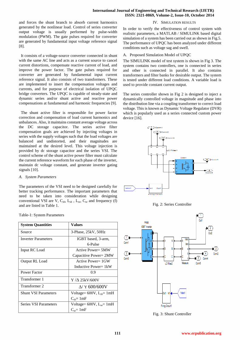
and forces the shunt branch to absorb current harmonics
generated by the nonlinear load. Control of series converter
output voltage is usually performed by pulse-width
modulation (PWM). The gate pulses required for converter
are generated by fundamental input voltage reference signal
[8].
It consists of a voltage-source converter connected in shunt
with the same AC line and acts as a current source to cancel
current distortions, compensate reactive current of load, and
improve the power factor. The gate pulses required for
converter are generated by fundamental input current
reference signal. It also consists of two transformers. These
are implemented to insert the compensation voltages and
currents, and for purpose of electrical isolation of UPQC
bridge converters. The UPQC is capable of steady-state and
dynamic series and/or shunt active and reactive power
compensations at fundamental and harmonic frequencies [9].
The shunt active filter is responsible for power factor
correction and compensation of load current harmonics and
unbalances. Also, it maintains constant average voltage across
the DC storage capacitor. The series active filter
compensation goals are achieved by injecting voltages in
series with the supply voltages such that the load voltages are
balanced and undistorted, and their magnitudes are
maintained at the desired level. This voltage injection is
provided by dc storage capacitor and the series VSI. The
control scheme of the shunt active power filter must calculate
the current reference waveform for each phase of the inverter,
maintain dc voltage constant, and generate inverter gating
signals [10].
A. System Parameters
The parameters of the VSI need to be designed carefully for
better tracking performance. The important parameters that
need to be taken into consideration while designing
conventional VSI are V, Csh, Lsh , Lse, Cse and frequency (f)
and are listed in Table 1.
Table-1: System Parameters
System Quantities Values
Source 3-Phase, 25kV, 50Hz
Inverter Parameters IGBT based, 3-arm,
6-Pulse
Input RC Load Active Power= 5MW
Capacitive Power= 2MW
Output RL Load Active Power= 1GW
Inductive Power= 1kW
Power Factor 0.9
Transformer 1 Y / 25kV/600V
Transformer 2 / Y 600/600V
Shunt VSI Parameters Voltage= 600V, Lsh= 1mH
Csh= 1mF
Series VSI Parameters Voltage= 600V, Lse= 1mH
Cse= 1mF
IV. SIMULATION RESULTS
In order to verify the effectiveness of control system with
realistic parameters, a MATLAB / SIMULINK based digital
simulation of a system has been carried out as shown in Fig.5.
The performance of UPQC has been analyzed under different
conditions such as voltage sag and swell.
A. Proposed Simulation Model of UPQC
The SIMULINK model of test system is shown in Fig 3. The
system contains two controllers, one is connected in series
and other is connected in parallel. It also contains
transformers and filter banks for desirable output. The system
is tested under different load conditions. A variable load is
used to provide constant current output.
The series controller shown in Fig 2 is designed to inject a
dynamically controlled voltage in magnitude and phase into
the distribution line via a coupling transformer to correct load
voltage. This is known as Dynamic Voltage Regulator (DVR)
which is popularly used as a series connected custom power
device [16].
Fig. 2: Series Controller
Fig. 3: Shunt Controller

Design and Implementation of UPQC to Solve Power Quality Problems
112 www.erpublication.org
Fig. 4: Proposed Simulation Model of UPQC
The purpose of the Shunt Controller is to compensate current
unbalance, current harmonics and load reactive power
demand fed to the supply [19]. The coupling of shunt
controller is three phase, in parallel to network and load
as shown in Fig 4. It works as current sources, connected in
parallel with the nonlinear load, generating harmonic currents
the load requires. This is same as the popularly known shunt
connected custom power device, D-STATCOM. UPQC is a
combination of DVR and D-STATCOM.
B. Simulation Output of UPQC
In order to show the impact of sag and swell variation, a
MATLAB/SIMULINK based simulation is carried out.
Fig. 5: Reference Voltage and Current
Fig. 5 shows the three phase reference voltage and current
waveforms when UPQC is not connected in system. These are
constant in phase as well as in amplitude. Fig 6 shows the
control firing pulses for bridge converters. Each bridge
contains six IGBTs and each IGBT requires a firing pulse at
its gate terminal. These input pulses are required to ON the
bridges.
Fig. 6: Control Firing Pulses for UPQC Bridges
C. Effect of Voltage Swell
A voltage swell of 50% is now introduced in the system for a
time span ranging from t=0.2 sec to t=0.4 sec, as shown in the
Fig. 7. Under this condition the series filter injects an out of
phase compensating voltage in the line through series
transformers. The currents are unbalanced and distorted; the
terminal voltages are also unbalanced and distorted.
Fig. 7: Input Voltage and Current at Swell of 50%
Fig. 8: Constant Output Voltage and Current with UPQC
when Voltage Swell of 50% has occurred
The load output profile in Fig. 8 shows the UPQC is
effectively maintaining the load bus voltage at desired
constant level even during the swell on the system such that
the loads are not affected by any voltage variation. In other
words, the extra power due to the voltage swell condition is
fed back to the source by taking reduced fundamental source
current. The proposed UPQC maintained the load voltage free
from swelling and at the desired level.
The above system model has been analyzed by varying
the voltage swell from 10% to 80% for a time span of 0.2
seconds ranging from t=0.2 sec to t=0.4 sec. The input
waveforms are highly unbalanced. The load output voltage

International Journal of Engineering and Technical Research (IJETR)
ISSN: 2321-0869, Volume-2, Issue-10, October 2014
113 www.erpublication.org
and current shows that the UPQC effectively maintains the
load bus output at desired constant level. It is seen that that
voltage and current levels are maintained at desirable levels
and the distortion is considerably reduced below 2%.
D. Effect of Voltage Sag
A voltage sag of 50% is now introduced on the same model of
the system for a time span ranging from t=0.2 sec to t=0.4 sec
as shown in Fig. 9. During this voltage sag condition, the
series APF is providing required voltage by injecting in phase
compensating voltage (50%). The load output waveforms
shown in Fig. 10 shows that UPQC is maintaining it at desired
constant voltage level at load even during the sag on the
system such that the loads cannot see any voltage variation.
Fig. 9: Input Voltage and Current at Sag of 50%
Fig. 10: Constant Output Voltage and Current with UPQC
when Voltage Sag of 50% Occurred
This system is again analyzed by varying the voltage sag from
10% to 80% for a time span of 0.2 sec ranging from t=0.2 sec
to t=0.4 sec. Before and after this time, the system is again at
normal working condition. The load output profile in all these
conditions show that it produces a constant output voltage and
current when UPQC is connected to a system.
This system is again analyzed by varying the voltage
sag from 10% to 80% for a time span of 0.2 sec ranging from
t=0.2 sec to t=0.4 sec. Before and after this time, the system is
again at normal working condition. The load output profile in
all these conditions show that it produces a constant output
voltage and current when UPQC is connected to a system.
E. Effect of Voltage Sag and Swell on Voltage and Current
with Increased Duration
A voltage swell and sag of 50% is now introduced in the
system for a time span ranging from t=0.5 sec to t=2 sec, as
shown in the Fig. 11 and Fig. 12 respectively. Under this
condition, the currents are unbalanced and distorted; the
terminal voltages are also unbalanced and distorted. The load
output waveforms shown in Fig. 13 shows that UPQC is
maintaining it at desired constant voltage level at load even
during the sag or swell for longer duration on the system.
Fig. 11: Input Voltage and Current at Swell of 50%
Fig. 12: Input Voltage and Current at Sag of 50%
Fig. 13: Constant Output Voltage and Current with UPQC
when Voltage Sag or Swell of 50% Occurred
F. Effect of Harmonics
The harmonics have the property that they are all periodic at
the fundamental frequency; therefore the sum of harmonics is
also periodic at that frequency. Harmonic frequencies are
correspondingly spaced by the width of the fundamental
frequency and can be found by repeatedly adding that
frequency. Harmonics are the multiple of the fundamental
frequency. They occur frequently when there are large
numbers of personal computers (single phase loads),
uninterruptible power supplies (UPSs), variable frequency
drives (AC and DC) or any electronic device using solid state
power switching supplies to convert incoming AC to DC.
Non-linear loads generate harmonics by drawing current in
abrupt short pulses as shown in fig 14 and its output is shown
in fig 15.

Design and Implementation of UPQC to Solve Power Quality Problems
114 www.erpublication.org
Fig. 14: Input Voltage and Current with 5th
order harmonics
Fig. 15: Constant Output Voltage and Current with 5th
Order
Harmonics Input
G. Effect of Interruption
A voltage interruption is a large decrease in RMS voltage to
less than a small percentile of the nominal voltage, or a
complete loss of voltage. Voltage disruptions may come from
accidents like faults and component malfunctions, or from
planned downtime. Short voltage interruptions are typically
the result of a malfunction of a switching device or a
deliberate or inadvertent operation of a fuse, circuit breaker,
or reclose in response to faults and disturbances. Long
interruptions are usually resulting of scheduled downtime,
where part of electrical power system is disconnected in order
to perform maintenance or repairs. When a three phase fault is
introduced in the system having duration 0.16 to 0.84 sec, it
generates an interruption in the input signal as shown in fig
16. When UPQC is connected within the system, it resolves
this power quality problem and provide us constant output
signal as shown in fig 17. The analysis of input and output
signals can be done by FFT Analysis tool provided in
Simulink block. The analysis of input waveform having
harmonics is given by fig 18. The upper part shows the input
voltage signal having 5th
order harmonics and lower part
shows its fundamental frequency components present in the
signal and also provides total harmonic distortion (THD).
Similarly, the fig 19 shows the output waveforms of input
harmonic signal and their FFT analysis. The THD in fig 20
shows that this output signal is distortion free.
Fig. 16: Input Voltage and Current Waveforms having
Harmonics and Interruption
Fig. 17: Output Voltage and Current Waveforms with UPQC
having No Harmonics and Interruption
0 0.1 0.2 0.3 0.4 0.5 0.6 0.7 0.8 0.9 1-2
-1
0
1
2x 10
4 Selected signal: 50 cycles. FFT window (in red): 2 cycles
Time (s)
0 100 200 300 400 500 600 700 800 900 10000
2
4
6
8
10
12
Frequency (Hz)
Fundamental (50Hz) = 1.348e+04 , THD= 16.39%
Mag (%
of F
undam
ental)
Fig. 18: Input THD having Harmonics and Interruption

International Journal of Engineering and Technical Research (IJETR)
ISSN: 2321-0869, Volume-2, Issue-10, October 2014
115 www.erpublication.org
0 100 200 300 400 500 600 700 800 900 10000
0.05
0.1
0.15
0.2
0.25
0.3
Frequency (Hz)
Fundamental (50Hz) = 635.8 , THD= 0.08%
Mag (
% o
f F
undam
enta
l)
0 0.1 0.2 0.3 0.4 0.5 0.6 0.7 0.8 0.9 1
-500
0
500
Selected signal: 50 cycles. FFT window (in red): 2 cycles
Time (s)
Fig. 19: Output THD having No Harmonics and Interruption
V. CONCLUSIONS
In this paper, the simulation results shows that UPQC can be
employed to reduce the distortion level and highly improve
the power quality of the system. Due to its reliability, it was
adopted as the optimal solution for the compensation of
voltage and current. This paper investigated the application of
UPQC for power quality improvement and implementation of
a flexible control strategy to enhance the performance of
UPQC. In order to protect critical loads from more voltage
harmonics, UPQC is suitable and satisfactory. The objectives
have been successfully realized through software
implementation in MATLAB/SIMULINK.
REFERENCES
[1] Nikita Hari, K.Vijayakumar and Subhranshu Sekhar Dash, “A Versatile
Control Scheme for UPQC for Power Quality Improvement”,
Proceedings of the International Conference on Emerging Trends in
Electrical and Computer Technology (ICETECT), pp 453-458, 23-24
March 2011.
[2] Srinivas Bhaskar Karanki, Mahesh K. Mishra and B. Kalyan Kumar,
“Comparison of Various Voltage Source Inverter based UPQC
Topologies”, Proceedings of the International Conference on Power
and Energy Systems (ICPS), pp 1-7, December 2011.
[3] Vinod Khadkikar, “Enhancing Electric Power Quality Using UPQC: A
Comprehensive Overview”, IEEE Transactions on Power Electronics,
Vol. 27, No. 5, pp 2284-2297, May 2012.
[4] Malabika Basu, S. P. Das and Gopal K. Dubey, “Performance Study of
UPQC-Q for Load Compensation and Voltage Sag Mitigation”,
Proceedings of the IEEE 28th Annual Conference of the Industrial
Electronics Society (IECON 02), Vol. 1, pp 698-703, November, 2002.
[5] V. Khadkikar, A. Chandra, A. O. Barry and T. D. Nguyen, “Application
of UPQC to Protect a Sensitive Load on a Polluted Distribution
Network”, IEEE Power Engineering Society General Meeting, 2006.
[6] A.Jeraldine Viji and M.Sudhakaran, “Generalized UPQC system with an
improved Control Method under Distorted and Unbalanced Load
Conditions”, Proceedings of the International Conference on
Computing, Electronics and Electrical Technologies (ICCEET), pp
193-197, 2012.
[7] Morris Brenna, Roberto Faranda and Enrico Tironi, “A New Proposal for
Power Quality and Custom Power Improvement: OPEN UPQC”, IEEE
Transactions on Power Delivery, Vol. 24, No. 4, pp 2107-2116,
October 2009.
[8] Vinod Khadkikar and Ambrish Chandra, “A New Control Philosophy for
a Unified Power Quality Conditioner (UPQC) to Coordinate
Load-Reactive Power Demand Between Shunt and Series Inverters”
IEEE Transactions On Power Delivery, Vol. 23, No. 4, October 2008.
[9] V. Khadkikar,A. Chandra, A. O. Barry and T. D. Nguyen, “Application
of UPQC to Protect a Sensitive Load on a Polluted Distribution
Network”, IEEE Power Engineering Society, General Meeting, 2006.
[10] B. S. Mohammed, K. S. Rama Rao and P. A. Nallagownden,
“Improvement of Power Quality of a Two Feeder System using Unified
Power Quality Conditioner”, Proceedings of the National Postgraduate
Conference (NPC), pp 1-6, September 2011.
[11] K. Palanisamy, J Sukumar Mishra, I. Jacob Raglend and D. P. Kothari,
“Instantaneous Power Theory Based Unified Power Quality
Conditioner (UPQC)”, 2010 Joint International Conference on Power
Electronics, Drives and Energy Systems (PEDES), pp 1-5, 20-23
December 2010.
[12] G. Siva Kumar, B. Kalyan Kumar and Mahesh K. Mishra, “Mitigation
of Voltage Sags with Phase Jumps by UPQC with PSO-Based ANFIS”,
IEEE Transactions on Power Delivery, Vol. 26, No. 4, pp 2761-2773,
October 2011.
[13] V. Khadkikar, A. Chandra, A. 0. Barry and T. D. Nguyen, “Conceptual
Study of Unified Power Quality Conditioner (UPQC)”, Proceedings of
the IEEE International Symposium on Industrial Electronics 2006,
Canada, Vol. 2, pp 1088-1093, July 2006.
[14] Subramanian Muthu and Jonathan M. Kim “Steady-State Operating
Characteristics of Unified Active Power Filters”, twelfth annual
Applied Power Electronics Conference and Exposition (APEC), Vol.
1, pp 199 – 205, February 1997.
[15] Sudeep Kumar R and Ganesan P, “250 kVA Unified Power Quality
Controller”, Proceedings of the IEEE Region 10 Conference
(TENCON), Hong Kong, pp 1 – 4, November 2006.
[16] Ramachandaramurthy V.K., Arulampalam A., FitzerC., Zhan C.,
Barnes M., Jenkins N., “Supervisory Control of Dynamic Voltage
Restorers”, IEEE Proceedings- Generation, Transmission and
Distribution, Vol. 151, No. 4, pp. 509-516, 11 July, 2004.
[17] Salmeron P., Litran S.P., “Improvement of the Electric Power
Quality Using Series Active and Shunt Passive Filters”, IEEE
Transactions on Power Delivery, Vol. 25, No. 2, pp. 1058-1067, April
2010.
[18] Saleh S.A., Moloney C.R., Rahman M.A., “Implementation of a
Dynamic Voltage Restorer System Based on Discrete Wavelet
Transforms”, IEEE Transactions on Power Delivery, Vol. 23, No. 4,
pp. 2366-2375, October 2008.
[19] Singh M., Khadkikar V., Chandra A., Varma R.K., 2011. Grid
Interconnection of Renewable Energy Sources at the Distribution Level
with Power-Quality Improvement Features, IEEE Transactions on
Power Delivery, Vol. 26, No. 1, pp. 307-315, January 2011.
[20] Singh B., Al-Haddad K., Chandra A., “A review of active filters for
Power Quality Improvement”, IEEE Transaction on Industrial
Electronics, Vol. 46, No. 5, pp. 960-971, August 2002.
Meenakshi Bhardwaj received her B.Tech
Degree in Electrical Engg. from
REC,Kurukshetra(KU, May 2002). Now, She is
persuing M.Tech in Electrical Engg. From G.G.S
College of Modern Technology, Punjab Technical
University, Kharar. She has worked with Purolator
India Ltd., Gurgaon as Operating Engineer (Sept.
1997 – Sept. 1999). Then worked as Lecturer in
Shri Krishan Polytechnic, Kurukshetra (July 2007 – July 2008) . She also
worked as HOD in Shri Krishan Polytechnic, Kurukshetra (From July
2008-Oct 2010) and then worked as Lecturer in SKIET, Kurukshetra (From
Nov 2010-Sep 2011). Her research interest in designing and modelling of
controllers using MATLAB.
Dr. Akhil Gupta received B.E (Electrical Engg) from
GZSCET, Bathinda (PTU, Jalandhar) in 1999 and
M.Tech in Electrical Engineering from Kay Jay group of
Institutes, Patiala (Institute of Advanced Studies In
Education, Rajasthan) in 2005. His Ph.D is in Power
Quality Evaluation of solar PV grid connected systems
from EE Department, NIT Kurukshetra, and Haryana.
He is now working as Associate Professor in Chandigarh University,
Gharuaan, District Mohali, Punjab, India. He has total of 14 years experience
in this field. His area of interest is in Application of renewable energy
systems into electrical power systems, controls, power quality, custom power
devices.