power quality improvement using unified...
TRANSCRIPT

POWER QUALITY IMPROVEMENT USING UNIFIED POWER QUALITY CONDITIONER (UPQC)
Piyush Anand
DEPARTMENT OF ELECTRICAL ENGINEERING NATIONAL INSTITUTE OF TECHNOLOGY ROURKELA
MAY, 2016
POWER QUALITY IMPROVEMENT USING UNIFIED POWER QUALITY CONDITIONER (UPQC)
Thesis submitted to
National Institute of Technology, Rourkela
For award of the degree
of
Master of Technology
by
Piyush Anand
Under the guidance of
Prof. Pravat Kumar Ray
&
Prof. Bidyadhar Subudhi
DEPARTMENT OF ELECTRICAL ENGINEERING NATIONAL INSTITUTE OF TECHNOLOGY ROURKELA
MAY, 2016

Department of Electrical Engineering
National Institute of Technology, Rourkela
CERTIFICATE
This is to certify that the project entitled "Power Quality Improvement Using Unified
Power Quality Conditioner (UPQC)" submitted by Piyush Anand (214EE4241) in partial
fulfilment of the requirements for the award of Master of Technology degree in Power
Electronics and Drives, Department of Electrical Engineering at National Institute of
Technology, Rourkela is an authentic work carried out by him under my supervision and
guidance. To the best of my knowledge, the matter embodied in this thesis has not been submitted
to any other university/Institute for the award of any Degree.
Place: Rourkela Prof. Pravat KumarRay
Date:
Prof. Bidyadhar Subudhi
Dept. Of Electrical Engineering,
National Institute of Technology,
Rourkela-769008

ACKNOWLEDGEMENT
On the submission of my thesis entitled “Power Quality Improvement Using Unified
Power Quality Conditioner (UPQC)”, I would like to extend my gratitude and sincere thanks
to my supervisor Prof. Pravat Kumar Ray & Prof. Bidyadhar Subudhi, Dept. of Electrical
Engineering for their constant motivation and support during the course work. I am very
thankful to them for giving me good basics in UPQC and Power Quality during the course
work, which makes a good part of the project. I truly appreciate and value their esteemed
guidance and encouragement in the beginning.
I also express my earnest thanks to the Head of the Department of Electrical
Engineering, NIT, Rourkela for providing all the possible facilities towards this work. I also
like to express my gratitude to research scholar Soumya Mishra who helped me in my
project work. I express my gratitude to other faculty members in the department. I would
like to thank all others who have consistently encouraged and gave me moral support,
without whose help it would be difficult to finish this project. I would like to thank my
parents and friends for their consistent support throughout.
Piyush Anand
Roll No. 214EE4241,
Dept. of Electrical Engineering,
National Institute of Technolgy,
Rourkela-769008
ABSTRACT
The advance use of power electronic devices introduces harmonics in the supply system
which creates a problem in the quality of power delivered. Good Power Quality is very much
important for our day to day use of appliances in both industrial and domestic sectors.
Researchers have tried and implemented many useful technology for removing all the
voltage and current related harmonic occurrence problems which in turn improves the
quality of power delivered to the power system. The prime focus of this thesis is the
implementation of control strategies like SRF theory and instantaneous power (p-q) for the
operation of Unified Power Quality Conditioner (UPQC) which is one of the recent
technology that includes both series and shunt active power filter operating at the same time
and thereby improves all the current and voltage related problem like voltage sag/swell,
flicker, etc. at the same time and helps in reduction of Total Harmonic Distortion (THD).
In this thesis it is shown via MATLAB simulation how UPQC model can be used to decrease
the % THD in source voltage, source current and load voltage waveforms created due to
non-linear/ sensitive loads usage.
i
List of Figures
Sl. No. Description Page No
1.1 Voltage sag found in supply voltage…………………………………………...2
1.2 Voltage swell found in supply voltage…………………………………………3
2.1 Principle of Single phase shunt active power filter…………………………….7
2.2 Unit vector Control scheme for shunt APF……………………………………10
3.1 p-q control strategy t generate reference current ……………………………..12
4.1 PLL block diagram……………………………………………………………19
4.2 SRF control for UPQC operation……………………………………………..22
5.1 MATLAB simulation of single phase shunt APF……………………………..25
5.2 Load current without shunt APF………………………………………………26
5.3 Load current Harmonic Spectrum without shunt APF………………………...26
5.4 Load current with shunt APF………………………………………………….26
5.5 Load current Harmonic Spectrum with shunt APF……………………………27
5.6 UPQC model to be simulated………………………………………………….27
5.7 Source voltage (a-phase) in non-linear load…………………………………...28
5.8 Source current (a-phase) in non-linear load…………………………………...29
5.9 Load voltage (a-phase) in non-linear load……………………………………..29
5.10 Load current (a-phase) in non-linear load……………………………………..29
5.11 Source voltage (a-phase) after UPQC compensation………………………….30
5.12 Source current (a-phase) after UPQC compensation………………………….30
5.13 Load voltage (a-phase) after UPQC compensation……………………………31
5.14 Load current (a-phase) after UPQC compensation……………………………31
5.15 DC link voltage across capacitor………………………………………………31
ii
List of Abbreviations
Abbreviations Description
APF Active Power Filter
UPQC Unified Power Quality Conditioner
THD Total Harmonic Distortion
PQ Power Quality
PLL Phase Locked Loop
PWM Pulse Width Modulation
IGBT Insulated Gate Bipolar Transistor
RMS Root Mean Square
SRF Synchronous Reference Frame
iii

List of TABLES
Table 5.1 UPQC simulation parameters
Table 5.2 Simulation of UPQC model with non-linear
load
iv

CONTENTS
Abstract i
List of Figures ii
List of Abbreviation iii
List of Tables iv
Chapter-1 INTRODUCTION
1.1 Background………………………………………………………………………..1
1.2 Power Quality Problem……………………………………………………………2
1.2.1 Voltage Sag and effects………………………………………………………….2
1.2.2 Voltage swell and effects………………………………………………………..4
1.3 Active Power Filter……………………………………………………………….4
1.4 Literature Review…………………………………………………………………5
1.5 Motivation………………………………………………………………………...6
1.6 Organisation of the thesis………………………………………………………….6
Chapter-2 Single Phase Shunt Active Power Filter
2.1 Introduction………………………………………………………………………...7
2.2 Design of system……………………………………………………………………8
2.2.1 Voltage Controller………………………………………………………………….9
2.2.2 Reference Current Generation……………………………………………………..10
Chapter-3 P-Q Theory and Analysis
3.1 Introductio ………………………………………………………………………….11
3.2 Instantaneous Power Theory………………………………………………………...11

3.3 Analysis of p-q theory……………………………………………………………….12
3.4 Non linear load……………………………………………………………………....15
3.5 Compensation Strategy……………………………………………………………...17
Chapter-4 Synchronous Reference Frame Control of UPQC 4.1 Introduction………………………………………………………………………....18 4.2 𝐼𝑑 & 𝐼𝑞 component definition……………………………………………………….18 4.3 Modified Phase Locked Loop……………………………………………………....19 4.4 Reference-Voltage Signal Generation………………………………………….......20 for Series APF 4.5 Reference-Current Signal Generation……………………………………………....22 for Shunt APF Chapter-5 MATLAB & Simulation Results 5.1 Simulation of single phase shunt APF……………………………………………..25 5.2 Simulation of UPQC model with non-linear load …………………………………28 Conclusion & Future Work………………………………………………………..33 References………………………………………………………………………....34

1 Introduction
INTRODUCTION
1.1 BACKGROUND
In the present scenario non-linear loads have become extremely important and people are
becoming dependent on it. Few of these non-linear loads are televisions, printing and fax machines,
rectifiers, inverters, speed drives, AC, etc. Harmonics are introduced in the lines due to the
extensive use of these loads in our everyday purpose. The stability of any electrical devices
depends on its voltage and current waveforms. If the fundamental waveform is sinusoidal, and its
harmonics are sinusoidal too then these harmonics occurs in integral multiples of the fundamental
waveform. Due to these harmonic distortion created by nonlinear loads several problems are
caused in the appliances used in our purpose like: motor getting overheated, increase in several
types of losses, permanent damage of equipment in the worst case, high error in meter reading,
etc. Hence removal of these harmonics or harmonic mitigation from voltage and current
waveforms are of great concern for electrical engineers. Due to the harmonics introduction in the
lines by the nonlinear loads other problems of concern are voltage swell, voltage sag, flicker
occurring in voltage, etc and thereby disturbing he overall power supply.
In older days passive filters using tuned LC components were in very much use for improvement
of power quality by removing voltage and current harmonics. But due to its high cost, resonance
problems, large size and many more these filters are not in much use in the present days. All these
problems are now improved by the use of active power filters(APF) and more advanced hybrid
filters using several new technology. Series Active Filter is utilised for mitigation of voltage
quality problems and Shunt Active Filter(SAF) is helpful for removing the disturbances present in
the current waveforms.

2 Introduction
1.2 Power Quality(PQ) Problems
The voltage quality which a consumer gets for operation of load or given from some particular
utility is very important. PQ problem deals with deviation of voltage/current from their ideal
sinusoidal waveforms. The power quality became mainly poor at those typical locations where we
connect the loads in the grid. Power Quality has its various definitions and importance as per the
its usage by which we define them in the process. From designer perspective, PQ is defined as that
there should be no variation in voltage and there should be complete absence of noise generated
in grounding system. From the point of view of an utility engineer, it is voltage availability or
outage minutes. For the end users how much feasible is the available power in order to drive
various types of loads is defined as power quality.
1.2.1 Voltage Sag
Voltage Sag is the decrease in rms voltage of power frequency for a time span of half cycles to 1
minute. Voltage sag is a severe and drastic PQ issue especially with sensitive loads which are
voltage sensitive like equipment for control processing, adjustable speed drives (ASD) and
computers.
Fig. 1.1 Voltage sag found in supply voltage
It can also be manipulated as a short duration reduction in voltage as a consequence of a sudden
abrupt increase in current value. Few of the common industrial situations where voltage sags could
be visible are energizing of transformer, starting process of motor, and typical faults.

4 Introduction
Effects:
Few drastic effect found due to voltage sag problems includes relay getting tripped, loads
,malfunctioning, damage or complete failure of the equipment found in load end.
1.2.2 Voltage Swell
Voltage swell is a sudden increase in the rms supply voltage varying in a range from 1.1p.u.
to 1.7 p.u., with a approximate time range of from half a cycle to 1 min. These appear due to large
loads sudden shutdown, capacitor banks getting energized, or due to few faults produced inside
the power system. Its occurrence probability appear when compared to voltage sags is very much
less, but these are more harmful to sensitive equipment/non-linear loads.
Fig. 1.2 Voltage swell found in supply voltage
Effects:
The effects are similar like voltage sag such as damage or equipment relay tripping which
leads to failure of complete system in operation.
1.3Active Power Filters
APF’s are the electrical equipment which are connected sometimes as series model or shunt model
and sometimes as a combination of both series and shunt filters. UPQC is a model where both
series and shunt APF connected via a common dc link capacitor are implemented in one circuit
only and they help to solve all voltage and current harmonics problems simultaneously. Series
APF are used for solving only voltage harmonics problems like voltage sag, swell, flickering etc

5 Introduction
whereas shunt APF is used for solving only current harmonics problems and hence improves
power factor by supplying reactive power continuously regulates DC link voltage. Hence service
reliability is achieved with the combination of series and shunt filter in the form of UPQC.
1.4 Literature Review
In [1] it is shown to construct an APF with hysteresis current control method. A simple
proportional-integral(PI) controller is brought in use in order regulating the average dc bus voltage
which thereby make the reference supply current peak value and supply voltage in phase and the
model is tested with different linear and nonlinear loads to remove the harmonics and reduce
reactive power.
In [2] the technology based on unit vector template generation from distorted input supply is used
for solving problems related with voltage and current harmonics in a basic UPQC model.
H.Akagi et al. [3] proposed the instantaneous active and reactive power concept. It describes a
instantaneous reactive power compensators that doesn’t uses a energy storage device but switching
devices. It proved that both harmonic currents and fundamental reactive power in transient states
can be removed. We understand the advanced control strategy i.e d-q-o method for compensating
the voltage harmonics and hence the voltage signal at series active filter is utilized to find the
reference signal for the parallel active filter using p-q theory.
Metin Kesler [4] proposed an advanced control method(SRF) to overcome the problems of power
quality through a three-phase UPQC under unbalanced load conditions. Its performance was
analyzed. The proposed control system helps in improving the power quality at the point of
common coupling (PCC) on power distribution system under unbalanced load conditions and non-
ideal mains voltage by compensating the current and voltage harmonics and the reactive power..
In [5] we see control strategy is dealing with the series inverter controller where amplitude
modulation ratio of series inverter sinusoidal PWM voltage controller is regularly adjusted to
follow the actual dc link voltage and not the reference dc link voltage. Yash Pal [6], presents a
control strategy for a three-phase four-wire Unified Power Quality (UPQC). A three-phase, four
6 Introduction
leg VSI is used for shunt APF and a three-phase, three legs VSI for realising the series APF. Unit
vector template control technique is used to get the for controlling the series APF, while Icosɸ
control is used for control of shunt APF. This method ensures, mitigation of voltage and current
harmonics, load balancing ,voltage swell and sag and voltage dips. This method helps effectively
in reduction of computational time and number of sensors.
1.5 Motivation:
From the literature review it is followed that it is a huge task to nullify the undesirable current
harmonics and also compensate reactive power requirement in power system. The drawback of
traditional LC filter discussed above creates a doorway for the active power filters to make the
task easier with better advanced topology suggested by researchers. These control strategy plays
an important role in better performance of APF. From the above literature review it has been seen
that hybrid APF is a multidisciplinary research area. There are various types of problem arising
due to nonlinear/sensitive loads in power system. To deal with these problem and also guarantying
that the system remains stable is a challenging for any researcher. This gave me the motivation to
design a UPQC model using p-q theory and SRF based theory.
Organisation of the Thesis:
The thesis consists of five chapters. Here the chapters are organised in a systematic manner to meet
the objective of the entitled project. The chapters are given as follows:-
Chapter 1 deals with introduction and problem faced in the power system due to
nonlinear/sensitive loads. A brief literature review on different control strategy has been discussed
for the operation of APF.
Chapter 2 deals with the design and analysis of operation of single phase shunt APF. Here we go
through the control strategy namely generation of unit vector template, principle of working of
shunt APF and the use of voltage controller for generating the gating sequence for operation of
filter is studied in detailed manner.

6 Introduction
Chapter 3 deals with a developed control strategy called instantaneous power theory(p-q). Here
we study detailed analysis along with nonlinear load dynamics. We go through the certain
transformation from a-b-c frame to 𝛼 − 𝛽 − 0 frame of reference and see how this control helps
to generate reference source current
Chapter 4 deals with Synchronous reference frame (SRF) theory where we also study the modified
phase locked loop (PLL) for highly distorted conditions. A detailed analysis along with
transformation matrix is studied in his chapter.
Chapter 5 we go through the simulation of a single phase shunt APF and then a UPQC model to
realise and see how actually the nonlinear disturbs the power system by going through voltage and
current waveforms and then see how UPQC model helps to mitigate all these problems.
7 Single Phase Shunt Active Power Filter
Single Phase Shunt Active Power Filter
2.1 Introduction
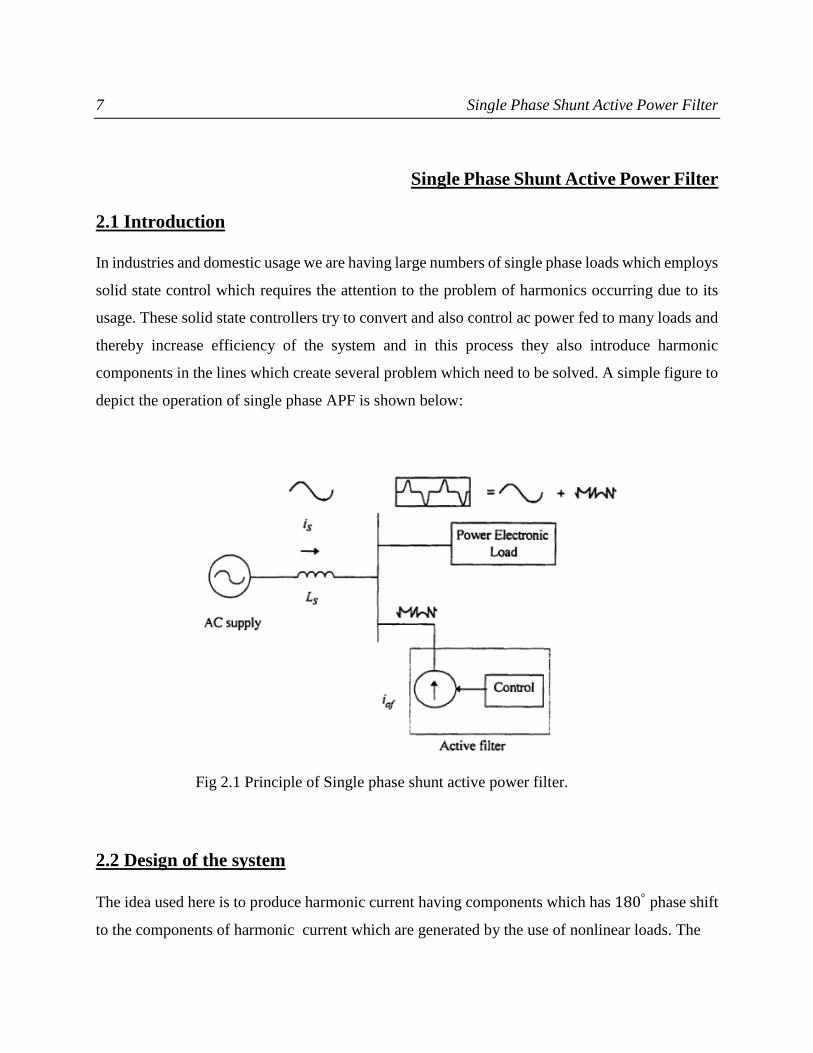
In industries and domestic usage we are having large numbers of single phase loads which employs
solid state control which requires the attention to the problem of harmonics occurring due to its
usage. These solid state controllers try to convert and also control ac power fed to many loads and
thereby increase efficiency of the system and in this process they also introduce harmonic
components in the lines which create several problem which need to be solved. A simple figure to
depict the operation of single phase APF is shown below:
Fig 2.1 Principle of Single phase shunt active power filter.
2.2 Design of the system
The idea used here is to produce harmonic current having components which has 180° phase shift
to the components of harmonic current which are generated by the use of nonlinear loads. The
8 Single Phase Shunt Active Power Filter
concept is totally based on injecting harmonic current in the ac system similar in amplitude but
opposite in phase when compared with load current waveform harmonics.
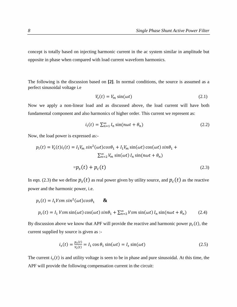
The following is the discussion based on [2]. In normal conditions, the source is assumed as a
perfect sinusoidal voltage i.e
𝑉𝑠(𝑡) = 𝑉𝑚 sin (𝜔𝑡) (2.1)
Now we apply a non-linear load and as discussed above, the load current will have both
fundamental component and also harmonics of higher order. This current we represent as:
𝑖𝑙(𝑡) = ∑ 𝐼𝑛 sin(𝑛𝜔𝑡 + 𝜃𝑛)∞𝑛=1 (2.2)
Now, the load power is expressed as:-
𝑝𝑙(𝑡) = 𝑉𝑠(𝑡)𝑖𝑙(𝑡) = 𝐼1𝑉𝑚 𝑠𝑖𝑛2(𝜔𝑡)𝑐𝑜𝑠𝜃1 + 𝐼1𝑉𝑚 sin(𝜔𝑡) cos(𝜔𝑡) 𝑠𝑖𝑛𝜃1 +
∑ 𝑉𝑚 sin(𝜔𝑡) 𝐼𝑛∞𝑛=2 sin (𝑛𝜔𝑡 + 𝜃𝑛)
=𝑝𝑠(𝑡) + 𝑝𝑐(𝑡) (2.3)
In eqn. (2.3) the we define 𝑝𝑠(𝑡) as real power given by utility source, and 𝑝𝑐(𝑡) as the reactive
power and the harmonic power, i.e.
𝑝𝑠(𝑡) = 𝐼1𝑉𝑠𝑚 𝑠𝑖𝑛2(𝜔𝑡)𝑐𝑜𝑠𝜃1 &
𝑝𝑐(𝑡) = 𝐼1 𝑉𝑠𝑚 sin(𝜔𝑡) cos(𝜔𝑡) 𝑠𝑖𝑛𝜃1 + ∑ 𝑉𝑠𝑚 sin(𝜔𝑡) 𝐼𝑛∞𝑛=2 sin (𝑛𝜔𝑡 + 𝜃𝑛) (2.4)
By discussion above we know that APF will provide the reactive and harmonic power 𝑝𝑐(𝑡), the
current supplied by source is given as :-
𝑖𝑠(𝑡) =𝑝𝑠(𝑡)
𝑉𝑠(𝑡)= 𝐼1 cos 𝜃1 sin(𝜔𝑡) = 𝐼𝑠 sin (𝜔𝑡) (2.5)
The current 𝑖𝑠(𝑡) is and utility voltage is seen to be in phase and pure sinusoidal. At this time, the
APF will provide the following compensation current in the circuit:

9 Single Phase Shunt Active Power Filter
𝑖𝑐(𝑡) = 𝑖𝑙(𝑡) − 𝑖𝑠(𝑡) (2.6)
2.2.1 Voltage Controller
One kind of voltage controller namely P-I (proportional-integral) controller has been utilised here
for the purpose of regulating voltage across dc bus capacitor in the APF. The voltage across the dc
bus capacitor (𝑉𝑑𝑐) is noted here using a voltmeter and then compared with reference constant
voltage (𝑉𝑟). The resulted error in voltage (𝑉𝑒(𝑛)) at a particular sample say nth has been expressed
as following :
𝑉𝑒(𝑛) = 𝑉𝑟(𝑛) − 𝑉𝑑𝑐(𝑛) (2.7)
The error is passed through the PI voltage controller and the output 𝑉𝑜(𝑛) at the nth sample interval
is given by:-
𝑉𝑜(𝑛) = 𝑉𝑜(𝑛−1) + 𝐾𝑝𝑝[𝑉𝑒(𝑛) − 𝑉𝑒(𝑛−1)] + 𝐾𝑖𝑖𝑉𝑒(𝑛)
(2.8)
Here, 𝐾𝑖𝑖 and 𝐾𝑝𝑝 are defined as integral gain constant & proportional gain constant and in PI
controller. 𝑉𝑜(𝑛−1)and 𝑉𝑒(𝑛−1) are the controller output & error in voltage at (n - 1)th sampling
instant. This output 𝑉𝑜(𝑛) of the PI controller has been limited to safe permissible value then this
limited output is considered as maximum value of utility or supply current 𝐼𝑠𝑚∗ .
2.2.2 Reference Current Generation
From the assumed supply voltage 𝑉𝑠(𝑡) = 𝑉𝑚 sin(𝜔𝑡) , unit vector template is calculated by the
following equation :
𝑢(𝑡) =𝑉𝑠(𝑡)
𝑉𝑠𝑚= sin(𝜔𝑡) (2.9)
10 Single Phase Shunt Active Power Filter
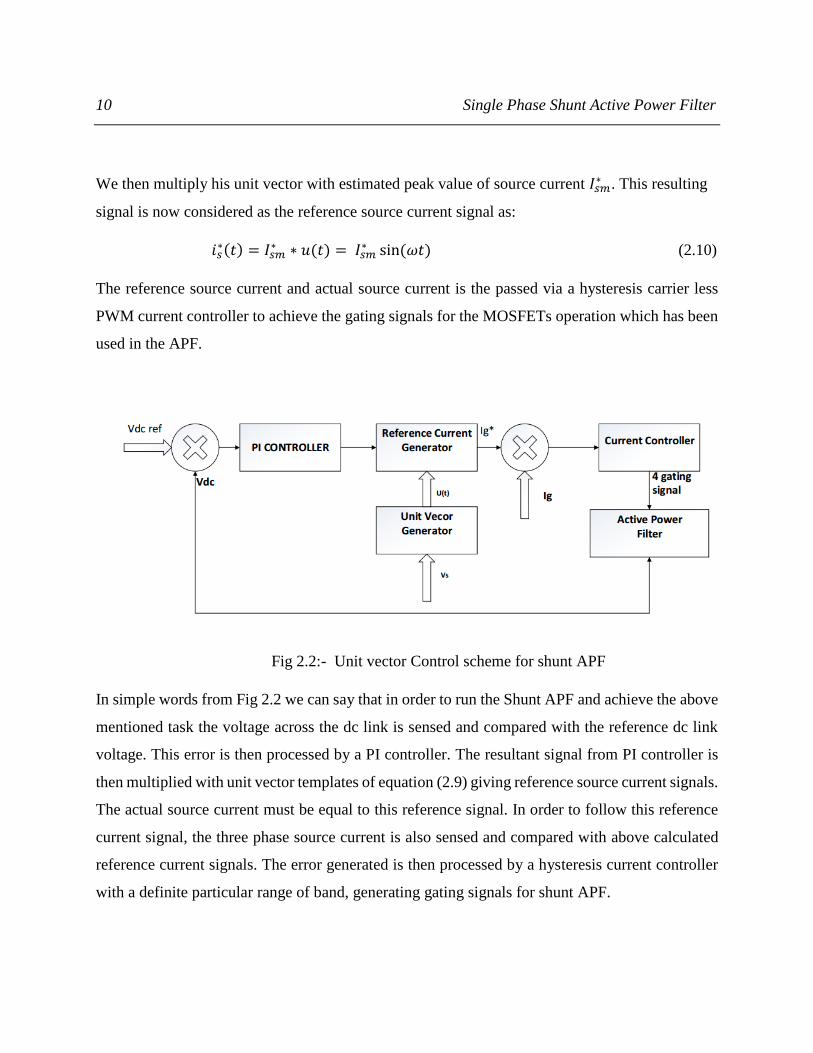
We then multiply his unit vector with estimated peak value of source current 𝐼𝑠𝑚∗ . This resulting
signal is now considered as the reference source current signal as:
𝑖𝑠∗(𝑡) = 𝐼𝑠𝑚
∗ ∗ 𝑢(𝑡) = 𝐼𝑠𝑚∗ sin(𝜔𝑡) (2.10)
The reference source current and actual source current is the passed via a hysteresis carrier less
PWM current controller to achieve the gating signals for the MOSFETs operation which has been
used in the APF.
Fig 2.2:- Unit vector Control scheme for shunt APF
In simple words from Fig 2.2 we can say that in order to run the Shunt APF and achieve the above
mentioned task the voltage across the dc link is sensed and compared with the reference dc link
voltage. This error is then processed by a PI controller. The resultant signal from PI controller is
then multiplied with unit vector templates of equation (2.9) giving reference source current signals.
The actual source current must be equal to this reference signal. In order to follow this reference
current signal, the three phase source current is also sensed and compared with above calculated
reference current signals. The error generated is then processed by a hysteresis current controller
with a definite particular range of band, generating gating signals for shunt APF.

11 PQ Theory & Analysis
PQ Theory & Analysis
3.1 INTRODUCTION
The standards in Power quality (IEEE-519) has compelled the engineers for limiting the total
harmonic distortion (THD) to an acceptable range which is mostly caused due to daily and regular
usage of power electronic devices in industries and domestic appliances. The total harmonic
distortion, or THD, of a signal is a measurement of the harmonic distortion present and is defined
as the ratio of the sum of the powers of all harmonic components to the power of the fundamental
frequency. Mathematically it is given as:-
THD%= 100 × √∑ (𝐼𝑠𝑛2
𝐼𝑠12 )∞
𝑛≠1 (3.1)
Instantaneous power theory or p-q theory is useful for the analysis of both transient-state and
steady state. In this method the commanding or driving signals required for filter operation is
obtained from instantaneous active and reactive power and hence there is no need of phase
synchronization of phase.
3.2 INSTANTANEOUS POWER THEORY
In [7] H.Akagi has defined a theory on the basis of instantaneous power in three phase system
either in the presence or absence of neutral wire. This p-q approach is valid for operation under all
conditions namely transient and steady state operation. This theory makes use of some famous
transformation models defined like Clarkes Transformation. Here the voltage and current
waveforms are sensed and then made to transform from a-b-c coordinates to 𝛼 − 𝛽 −
0 coordinates. After this transformation ,based on a certain set of equation we calculate active and
reactive power and then eliminate the power components having harmonics in it by passing
through a certain suitable low pass filter of suitable frequency. This new set of power and already
derived new voltages in a different coordinate namely 𝛼 − 𝛽 − 0 coordinates ,we again find out
the reference source current in this frame only and then using Inverse Clarkes Transformation we
convert this reference source current again back to a-b-c coordinates. This new reference source

12 PQ Theory & Analysis
current is then compared against actual sensed source current waveforms and the error is driven
through a hysteresis controller with a certain band for getting the different gate pulse for the
operation of inverter. A simple block diagram explaining the complete operation of this important
p-q theory is given below:-
Fig3.1 p-q control strategy to generate reference current
3.3 Analysis of P-Q Approach
Clarkes transformation needed for converting source voltage and current from a-b-c to 𝛼 − 𝛽 − 0
coordinate is given by following matrix:-

13 PQ Theory & Analysis
[
𝑉0𝑠
𝑉𝛼𝑠
𝑉𝛽𝑠
] = √2
3
[
1
√2
1
√2
1
√2
1−1
2
−1
2
0√3
2−
√3
2 ]
[
𝑉𝑠𝑎𝑉𝑠𝑏
𝑉𝑠𝑐
] (3.2)
Similarly current transformation is:-
[
𝑖0𝑠
𝑖𝛼𝑠
𝑖𝛽𝑠
] = √2
3 ||
1
√2
1
√2
1
√2
1−1
2
−1
2
0√3
2
−√3
2
|| [
𝑖𝑠𝑎𝑖𝑠𝑏𝑖𝑠𝑐
] (3.3)
3-∅ instantaneous power is given by:-
𝑃3∅(𝑡) = 𝑉𝑠𝑎𝑖𝑠𝑎 + 𝑉𝑠𝑏𝑖𝑠𝑏 + 𝑉𝑠𝑐𝑖𝑠𝑐 = 𝑉𝛼𝑠𝑖𝛼𝑠 + 𝑉𝛽𝑠𝑖𝛽𝑠 + 𝑉0𝑠𝑖0𝑠
= 𝑝𝑎(𝑡) + 𝑝𝑏(𝑡) + 𝑝𝑐(𝑡) = 𝑝𝛼𝑠(𝑡) + 𝑝𝛽𝑠(𝑡) + 𝑝0𝑠(𝑡)
= 𝑝𝑟(𝑡) + 𝑝0𝑠(𝑡) (3.4)
Here we define 𝑝𝑟(𝑡) = 𝑝𝛼𝑠(𝑡) + 𝑝𝛽𝑠
(𝑡) as instantaneous real power & 𝑝𝑜𝑠(𝑡) = 𝑝0𝑠(𝑡) as inst.
Power of zero sequence.
Here we can note down an important benefit of this transformation in which separation of system
zero sequence component is easily done.
The active (Ps) and reactive power (Qs) is then calculated by the following equations:-
[𝑃𝑠
𝑄𝑠] = [
𝑉𝛼𝑠 𝑉𝛽𝑠
−𝑉𝛽𝑠 𝑉𝛼𝑠] [
𝑖𝛼𝑠
𝑖𝛽𝑠] (3.5)
Hence from above matrix we can write 𝑄𝑠= 𝑉𝛼𝑠𝑖𝛽𝑠 − 𝑉𝛽𝑠𝑖𝛼𝑠. In terms of a-b-c components
𝑄𝑠 is written as:-
𝑄𝑠 =[(𝑉𝑠𝑎−𝑉𝑠𝑏)𝑖𝑠𝑐 +(𝑉𝑠𝑏−𝑉𝑠𝑐)𝑖𝑠𝑎 +(𝑉𝑠𝑐−𝑉𝑠𝑎)𝑖𝑠𝑏]
√3 (3.6)
14 PQ Theory & Analysis
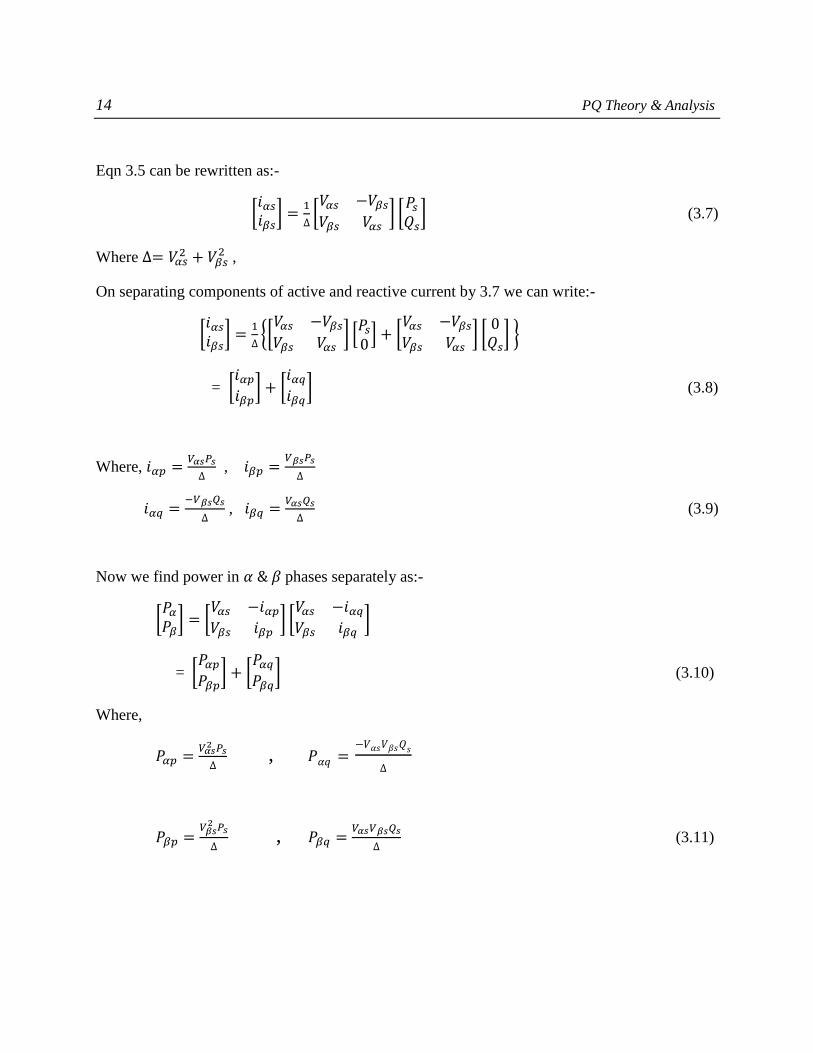
Eqn 3.5 can be rewritten as:-
[𝑖𝛼𝑠
𝑖𝛽𝑠] =
1
∆[𝑉𝛼𝑠 −𝑉𝛽𝑠
𝑉𝛽𝑠 𝑉𝛼𝑠] [
𝑃𝑠
𝑄𝑠] (3.7)
Where ∆= 𝑉𝛼𝑠2 + 𝑉𝛽𝑠
2 ,
On separating components of active and reactive current by 3.7 we can write:-
[𝑖𝛼𝑠
𝑖𝛽𝑠] =
1
∆{[
𝑉𝛼𝑠 −𝑉𝛽𝑠
𝑉𝛽𝑠 𝑉𝛼𝑠] [
𝑃𝑠
0] + [
𝑉𝛼𝑠 −𝑉𝛽𝑠
𝑉𝛽𝑠 𝑉𝛼𝑠] [
0𝑄𝑠
] }
= [𝑖𝛼𝑝
𝑖𝛽𝑝] + [
𝑖𝛼𝑞
𝑖𝛽𝑞] (3.8)
Where, 𝑖𝛼𝑝 =𝑉𝛼𝑠𝑃𝑠
∆ , 𝑖𝛽𝑝 =
𝑉𝛽𝑠𝑃𝑠
∆
𝑖𝛼𝑞 =−𝑉𝛽𝑠𝑄𝑠
∆ , 𝑖𝛽𝑞 =
𝑉𝛼𝑠𝑄𝑠
∆ (3.9)
Now we find power in 𝛼 & 𝛽 phases separately as:-
[𝑃𝛼
𝑃𝛽] = [
𝑉𝛼𝑠 −𝑖𝛼𝑝
𝑉𝛽𝑠 𝑖𝛽𝑝] [
𝑉𝛼𝑠 −𝑖𝛼𝑞
𝑉𝛽𝑠 𝑖𝛽𝑞]
= [𝑃𝛼𝑝
𝑃𝛽𝑝] + [
𝑃𝛼𝑞
𝑃𝛽𝑞] (3.10)
Where,
𝑃𝛼𝑝 =𝑉𝛼𝑠
2 𝑃𝑠
∆ , 𝑃𝛼𝑞 =
−𝑉𝛼𝑠𝑉𝛽𝑠𝑄𝑠
∆
𝑃𝛽𝑝 =𝑉𝛽𝑠
2 𝑃𝑠
∆ , 𝑃𝛽𝑞 =
𝑉𝛼𝑠𝑉𝛽𝑠𝑄𝑠
∆ (3.11)
15 PQ Theory & Analysis
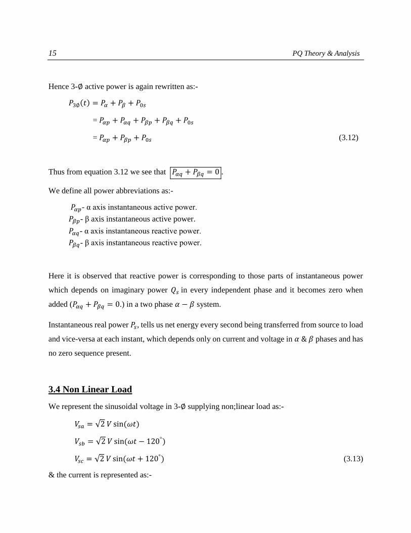
Hence 3-∅ active power is again rewritten as:-
𝑃3∅(𝑡) = 𝑃𝛼 + 𝑃𝛽 + 𝑃0𝑠
= 𝑃𝛼𝑝 + 𝑃𝛼𝑞 + 𝑃𝛽𝑝 + 𝑃𝛽𝑞 + 𝑃0𝑠
= 𝑃𝛼𝑝 + 𝑃𝛽𝑝 + 𝑃0𝑠 (3.12)
Thus from equation 3.12 we see that 𝑃𝛼𝑞 + 𝑃𝛽𝑞 = 0 .
We define all power abbreviations as:-
𝑃𝛼𝑝- α axis instantaneous active power.
𝑃𝛽𝑝- β axis instantaneous active power.
𝑃𝛼𝑞- α axis instantaneous reactive power.
𝑃𝛽𝑞- β axis instantaneous reactive power.
Here it is observed that reactive power is corresponding to those parts of instantaneous power
which depends on imaginary power 𝑄𝑠 in every independent phase and it becomes zero when
added (𝑃𝛼𝑞 + 𝑃𝛽𝑞 = 0.) in a two phase 𝛼 − 𝛽 system.
Instantaneous real power 𝑃𝑠, tells us net energy every second being transferred from source to load
and vice-versa at each instant, which depends only on current and voltage in 𝛼 & 𝛽 phases and has
no zero sequence present.
3.4 Non Linear Load
We represent the sinusoidal voltage in 3-∅ supplying non;linear load as:-
𝑉𝑠𝑎 = √2 𝑉 sin(𝜔𝑡)
𝑉𝑠𝑏 = √2 𝑉 sin(𝜔𝑡 − 120°)
𝑉𝑠𝑐 = √2 𝑉 sin(𝜔𝑡 + 120°) (3.13)
& the current is represented as:-

16 PQ Theory & Analysis
𝑖𝑠𝑎 = ∑ √2∞𝑛=1 𝐼𝑛 sin(𝑛𝜔𝑡 − ∅𝑛)
𝑖𝑠𝑏 = ∑ √2∞𝑛=1 𝐼𝑛 sin[𝑛(𝜔𝑡 − 120°) − ∅𝑛 ]
𝑖𝑠𝑐 = ∑ √2∞𝑛=1 𝐼𝑛 sin[(𝑛𝜔𝑡 + 120°) − ∅𝑛] (3.14)
Then in 𝛼 − 𝛽 system we can write:-
𝑖𝛼𝑠 = ∑2
√3∞𝑛=1 𝐼𝑛 sin(𝑛𝜔𝑡 − ∅𝑛)[1 − cos(𝑛 120°)]
𝑖𝛽𝑠 = ∑ 2∞𝑛=1 𝐼𝑛 cos(𝑛𝜔𝑡 − ∅𝑛)[sin (𝑛𝜔120°)]
𝑖0𝑠 =1
√3(𝑖𝑠𝑎 + 𝑖𝑠𝑏 + 𝑖𝑠𝑐)
= ∑ √6∞𝑛=1 𝐼3𝑛 sin(3𝑛𝜔𝑡 − ∅3𝑛) (3.15)
The power component is given by:-
𝑃𝑠 = 𝑉𝛼𝑠𝑖𝛼𝑠 + 𝑉𝛽𝑠𝑖𝛽𝑠 = 𝑃𝛼𝑝 + 𝑃𝛽𝑝
=3𝑉𝐼1 cos(∅) − 3𝑉𝐼2 cos(3𝜔𝑡 − ∅2) + 3𝑉𝐼4 cos( 3𝜔𝑡 + ∅4) − 3𝑉𝐼5 cos(6𝜔𝑡 − ∅5) + ⋯
(3.16)
𝑄𝑠 = 𝑉𝛼𝑠𝑖𝛽𝑠 − 𝑉𝛽𝑠𝑖𝛼𝑠
=3𝑉𝐼1 sin(∅1) − 3𝑉𝐼2 sin(3𝜔𝑡 − ∅2) + 3𝑉𝐼4 sin( 3𝜔𝑡 + ∅4) − 3𝑉𝐼5 sin(6𝜔𝑡 − ∅5) + ⋯
(3.17)
We can write above expression as:-
𝑃𝑠 = �� + �� & 𝑄𝑠 = �� + ��
Both expressions represents mean value and alternating components and mean value equal to
zero.The harmonic power is give by :- 𝐻 = √𝑃2 + 𝑄2 (3.18)
�� & �� are rms values of �� 𝑎𝑛𝑑 �� respectively.
17 PQ Theory & Analysis
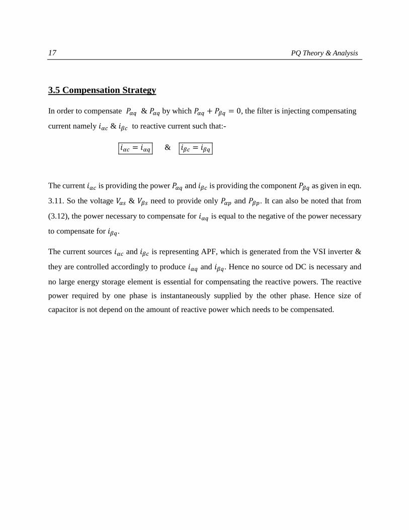
3.5 Compensation Strategy
In order to compensate 𝑃𝛼𝑞 & 𝑃𝛼𝑞 by which 𝑃𝛼𝑞 + 𝑃𝛽𝑞 = 0, the filter is injecting compensating
current namely 𝑖𝛼𝑐 & 𝑖𝛽𝑐 to reactive current such that:-
𝑖𝛼𝑐 = 𝑖𝛼𝑞 & 𝑖𝛽𝑐 = 𝑖𝛽𝑞
The current 𝑖𝛼𝑐 is providing the power 𝑃𝛼𝑞 and 𝑖𝛽𝑐 is providing the component 𝑃𝛽𝑞 as given in eqn.
3.11. So the voltage 𝑉𝛼𝑠 & 𝑉𝛽𝑠 need to provide only 𝑃𝛼𝑝 and 𝑃𝛽𝑝. It can also be noted that from
(3.12), the power necessary to compensate for 𝑖𝛼𝑞 is equal to the negative of the power necessary
to compensate for 𝑖𝛽𝑞.
The current sources 𝑖𝛼𝑐 and 𝑖𝛽𝑐 is representing APF, which is generated from the VSI inverter &
they are controlled accordingly to produce 𝑖𝛼𝑞 and 𝑖𝛽𝑞. Hence no source od DC is necessary and
no large energy storage element is essential for compensating the reactive powers. The reactive
power required by one phase is instantaneously supplied by the other phase. Hence size of
capacitor is not depend on the amount of reactive power which needs to be compensated.

18 SRF control of UPQC
Synchronous Reference Frame Control of UPQC
4.1 INTRODUCTION
SRF controlling method for the operation of UPQC model is very similar to instantaneous reactive
power theory method. A major feature this algorithm pursues is that only load current is essential
here for the generation of reference current and hence disturbances present in source or distortions
present in voltage have will leave no negative impact to the performance of the designed UPQC
system. In the given proposed SRF method for UPQC we have optimized the system
without using transformer voltage, load, and filter current measurement, .This reduces numbers of
measurements are and thereby improving system performance.
In this approach signals of current & voltage are first sensed and then transformed to a certain
rotating frame (d−q−0). Here, the transformation angle (ωt) is representing angular position of
proposed reference frame .This 𝜔t is rotating at constant speed and is synchronized with the 3-∅
ac voltage. Under the set condition of nonlinear load, load reactive currents and harmonic current
is found by PLL algorithms. After this, currents having same magnitude but with reverse phase is
produced and injected to the proposed system for compensating neutral current, harmonics, and
reactive power. In the stationary reference frame as discussed in chapter 3, α−β−0 coordinates are
stationary, while in the SRF, d−q−0 coordinate is rotating in synchronism with supply voltages.
4.2 𝑰𝒅 & 𝑰𝒒 Components Definition
From the proposed SRF theory “d” coordinate component of current namely 𝑖𝑑 , is corresponding
to positive-sequence and this component is always in phase with voltage. The “q” coordinate
component of current namely 𝑖𝑞 is found to be perpendicular to the 𝑖𝑑 component of the current,
This 𝑖𝑞is called negative sequence reactive current. The “0” coordinate component of current is
found to be orthogonal to both 𝑖𝑑 & 𝑖𝑞 and we name it as zero sequence component of the current.
If 𝑖𝑞 is found to be negative, the load will be pursuing inductive reactive power and if it is positive,
19 SRF control of UPQC
then it will be having a capacitive reactive power. In the proposed nonlinear power systems, 𝑖𝑑 & 𝑖𝑞
components will have both oscillating components (𝑖�� & 𝑖��) and average components (𝑖�� & 𝑖��), as
mentioned in the below equations.
𝑖𝑑 = 𝑖�� + 𝑖�� & 𝑖𝑞 = 𝑖�� + 𝑖�� (4.1)
In both the coordinates the oscillating part responds to oscillating component & the average part
responds to active current(𝑖�� ) and reactive current (𝑖��).Hence wherever APF applications are
made in operation our objective will be to separate the fundamental positive sequence component
so that harmonics can be eliminated or removed.
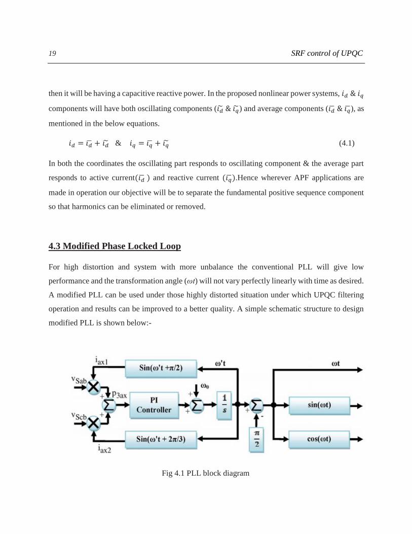
4.3 Modified Phase Locked Loop
For high distortion and system with more unbalance the conventional PLL will give low
performance and the transformation angle (ωt) will not vary perfectly linearly with time as desired.
A modified PLL can be used under those highly distorted situation under which UPQC filtering
operation and results can be improved to a better quality. A simple schematic structure to design
modified PLL is shown below:-
Fig 4.1 PLL block diagram
20 SRF control of UPQC
First we calculate the 3-∅ instantaneous source line voltages 𝑉𝑠𝑎𝑏 & 𝑉𝑠𝑐𝑏. This measured line
voltages is multiplied with auxiliary (𝑖𝑎𝑥1 & 𝑖𝑎𝑥2) feedback currents of unity amplitude, in which
one will lead leads 120° from the other to achieve auxiliary instantaneous active power (𝑝3𝑎𝑥).
This is passed through a P-I controller. The referred fundamental angular frequency (𝜔0 = 2πf) is
added to result of P-I controller for the purpose to stabilize output. The result is then passed through
an integrator block to get auxiliary transformation angle (ωt).The resultant produced ωt leads 90°
to system’s fundamental frequency; and hence −90° is added to integrator output for getting
system fundamental frequency. When this instantaneous power 𝑝3𝑎𝑥 reaches zero or gets low
frequency oscillation then PLL is said to reach a stable operating point. Also the output ωt will
reach fundamental positive sequence component of lien voltage.
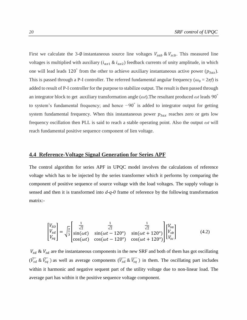
4.4 Reference-Voltage Signal Generation for Series APF
The control algorithm for series APF in UPQC model involves the calculations of reference
voltage which has to be injected by the series transformer which it performs by comparing the
component of positive sequence of source voltage with the load voltages. The supply voltage is
sensed and then it is transformed into d-q-0 frame of reference by the following transformation
matrix:-
[
𝑉𝑆𝑂
𝑉𝑠𝑑
𝑉𝑠𝑞
] = √2
3[
1
√2
1
√2
1
√2
sin (𝜔𝑡) sin (𝜔𝑡 − 120°) sin (𝜔𝑡 + 120°)cos (𝜔𝑡) cos (𝜔𝑡 − 120°) cos (𝜔𝑡 + 120°)
] [𝑉𝑠𝑎
𝑉𝑠𝑏
𝑉𝑠𝑐
] (4.2)
𝑉𝑠𝑑 & 𝑉𝑠𝑑 are the instantaneous components in the new SRF and both of them has got oscillating
(𝑉𝑠�� & 𝑉𝑠�� ) as well as average components (𝑉𝑠𝑑 & 𝑉𝑠𝑞
) in them. The oscillating part includes
within it harmonic and negative sequent part of the utility voltage due to non-linear load. The
average part has within it the positive sequence voltage component.

21 SRF control of UPQC
Hence we can say that :-
𝑉𝑠𝑑 = 𝑉𝑠𝑑 + 𝑉𝑠�� (4.3)
The harmonic part is separated by passing the d-component voltage 𝑉𝑠𝑑 via LPF. The output of
this LPF is only the average component 𝑉𝑠𝑑 . The zero and negative components namely 𝑉𝑠𝑞 & 𝑉𝑠0
of source voltage is terminated or made to zero for compensating harmonics of load voltage, and
unbalance. The reference load voltage is calculated by passing the new set of components of d-q-
0 frame via a inverse transformation which converts it again to the original a-b-c reference frame.
This inverse transformation called Inverse Parks transformation is shown below:-
[
𝑉𝑙𝑎∗
𝑉𝑙𝑏∗
𝑉𝑙𝑐∗] = √
2
3
[
1
√2sin (𝜔𝑡) cos(𝜔𝑡)
1
√2sin (𝜔𝑡 − 120°) cos(𝜔𝑡 − 120°)
1
√2sin (𝜔𝑡 + 120°) cos(𝜔𝑡 + 120°)]
[0
𝑉𝑠𝑑
0] (4.4)
The resultant reference voltages as above (𝑉𝑙𝑎∗ , 𝑉𝑙𝑏
∗ ,& 𝑉𝑙𝑐∗ ) and actual sensed load voltages
(𝑉𝑙𝑎 , 𝑉𝑙𝑏 & 𝑉𝑙𝑐 ) are compared and then passed via a sinusoidal pulse width modulation(PWM) for
controlling switching or gate signals for the series filter operation of IGBT used and to fight against
and remove all problems related with voltage as discussed in chapter 1 namely, harmonics in
voltage, sag/swell, voltage unbalance at the PCC. The whole idea of generating reference voltage
for series APF operation in UPQC model is depicted below:-

22 SRF control of UPQC
Fig 4.2 SRF control for UPQC operation
4.5 Reference-Source-Current Signal Generation for Shunt APF
The shunt APF as discussed in chapter 2 is useful for avoiding the problems related with the current
harmonics generated in our UPQC model with nonlinear load and also takes care for reactive
power compensation. The sensed source current are transformed to d−q−0 coordinates by the same
Parks transformation equation as given in 4.2, where the angular frequency (ωt) comes from
modified PLL discussed under section 4.3
[
𝑖𝑆𝑂
𝑖𝑠𝑑𝑖𝑠𝑞
] = 𝑇 [𝑖𝑠𝑎𝑖𝑠𝑏𝑖𝑠𝑐
] (4.5)
T is the Parks transformation matrix given in eqn 4.2

23 SRF control of UPQC
The new transformed instantaneous source current in d-q-0 frame namely 𝑖𝑠𝑑 & 𝑖𝑠𝑞 again includes
in it both oscillating components (𝑖𝑠�� & 𝑖𝑠�� ) and average components (𝑖𝑠𝑑 & 𝑖𝑠𝑞 ) as well.
Oscillating component will contain in it a combination of harmonic and negative sequence
component whereas the average component is including only positive sequence current component
which corresponds to reactive current. The zero sequence part namely 𝑖𝑠0 will appear under
unbalanced load conditions. In our SRF method average component of positive-sequence (𝑖𝑠𝑑 ) in
the d-axis and the zero- and negative-sequence component (𝑖𝑠0 & 𝑖𝑠𝑞) in the 0- and q-axes of the
source currents, in for compensating harmonics and unbalances produced in the non-linear load.
Series APF injects active power in the power system for compensating the active power losses of
the UPQC power circuit, which results in regulation of dc-link voltage across capacitor. A part of
active power is taken from the power system by shunt APF to make dc-link voltage constant. For
this task, the voltage of dc-link is compared with a set reference value (𝑉𝑑𝑐), and then passed via
a PI controller whose output is the required active current (𝑖𝑑𝑙𝑜𝑠𝑠). The d-component of source
current i.e 𝑖𝑠𝑑 is passed via a LPF to get its average component i.e (𝑖𝑠𝑑 ) . Now this average
component and required active current i.e 𝑖𝑑𝑙𝑜𝑠𝑠 are added to get fundamental reference
component. The whole phenomenon can be seen in Fig 4.2
𝑖𝑠𝑑′ = 𝑖𝑠𝑑 + 𝑖𝑑𝑙𝑜𝑠𝑠 (4.6)
The negative sequence and zero component of source current is set to zero to compensate,
distortion, harmonics, and reactive power in source current. . The reference source current is
produced by inverse Parks transformation as mention below:-
[
𝑖𝑠𝑎′
𝑖𝑠𝑏′
𝑖𝑠𝑐′
] = 𝑇−1 [0𝑖𝑠𝑑′
0] (4.7)
Where, 𝑇−1 is inverse Parks transformation as given in eqn 4.4

24 SRF control of UPQC
Bothe the measured and reference source current are compared now and passed via hysteresis band
current controller for getting the gating signals for operation of shunt APF in the given UPQC
model and thereby eliminating all the current related problem from the system.
25 MATLAB Simulation and Result
MATLAB Simulation and Result
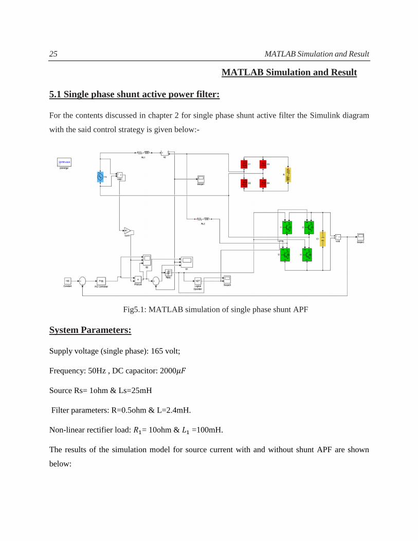
5.1 Single phase shunt active power filter:
For the contents discussed in chapter 2 for single phase shunt active filter the Simulink diagram
with the said control strategy is given below:-
Fig5.1: MATLAB simulation of single phase shunt APF
System Parameters:
Supply voltage (single phase): 165 volt;
Frequency: 50Hz , DC capacitor: 2000𝜇𝐹
Source Rs= 1ohm & Ls=25mH
Filter parameters: R=0.5ohm & L=2.4mH.
Non-linear rectifier load: 𝑅1= 10ohm & 𝐿1 =100mH.
The results of the simulation model for source current with and without shunt APF are shown
below:
26 MATLAB Simulation and Result
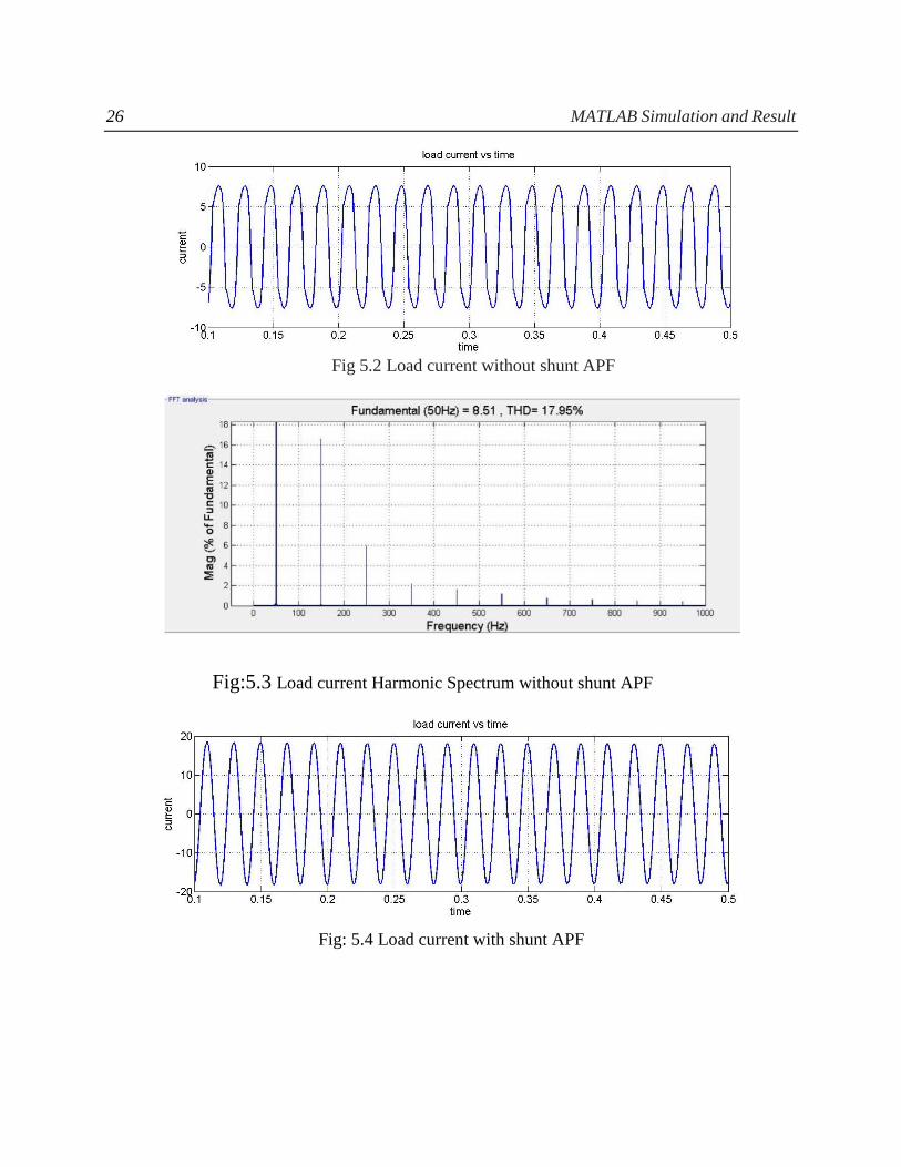
Fig 5.2 Load current without shunt APF
Fig:5.3 Load current Harmonic Spectrum without shunt APF
Fig: 5.4 Load current with shunt APF
27 MATLAB Simulation and Result
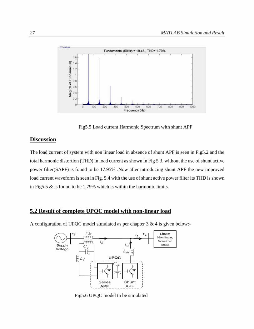
Fig5.5 Load current Harmonic Spectrum with shunt APF
Discussion
The load current of system with non linear load in absence of shunt APF is seen in Fig5.2 and the
total harmonic distortion (THD) in load current as shown in Fig 5.3. without the use of shunt active
power filter(SAPF) is found to be 17.95% .Now after introducing shunt APF the new improved
load current waveform is seen in Fig. 5.4 with the use of shunt active power filter its THD is shown
in Fig5.5 & is found to be 1.79% which is within the harmonic limits.
5.2 Result of complete UPQC model with non-linear load
A configuration of UPQC model simulated as per chapter 3 & 4 is given below:-
Fig5.6 UPQC model to be simulated

28 MATLAB Simulation and Result
Source voltage- 220V (phase) Shunt passive filter Parameter:
Lsh=3.5Mh, Rsh=5ohm Csh=4.7 𝜇𝐹
Frequency: 50Hz 𝑉𝑑𝑐 𝑟𝑒𝑓 = 500𝑉 C=2200 𝜇𝐹
Ls=1mH & Rs= 0.1ohm Non-linear load:
Rdc=30ohm Ldc=11.5mH
Series Filter inductance Lse=1.5mH
Series passive filter=Rse=5ohm Cse=25𝜇𝐹
P-I controller:
Kp=1.7 & Ki=0.2
Table 5.1 UPQC Simulation parameters
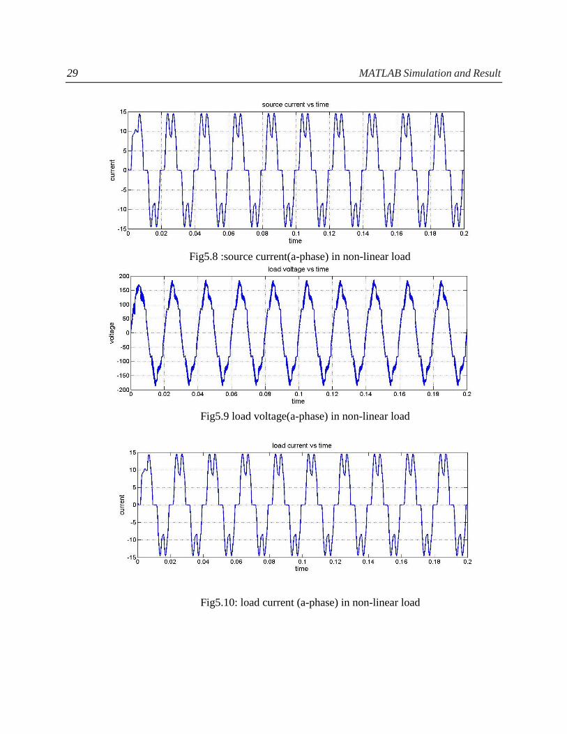
Before applying the UPQC in the system we sensed the source voltage, source current, load voltage
and load current in presence of the non-linear load in our system. Due to the non-linear load we
get distortions the supply voltage, current and also load voltage. The waveforms for all the sensed
voltages and currents before application of UPQC is shown below for A-phase:-
Fig5.7 : source voltage(a-phase) in non-linear load
29 MATLAB Simulation and Result
Fig5.8 :source current(a-phase) in non-linear load
Fig5.9 load voltage(a-phase) in non-linear load
Fig5.10: load current (a-phase) in non-linear load
30 MATLAB Simulation and Result
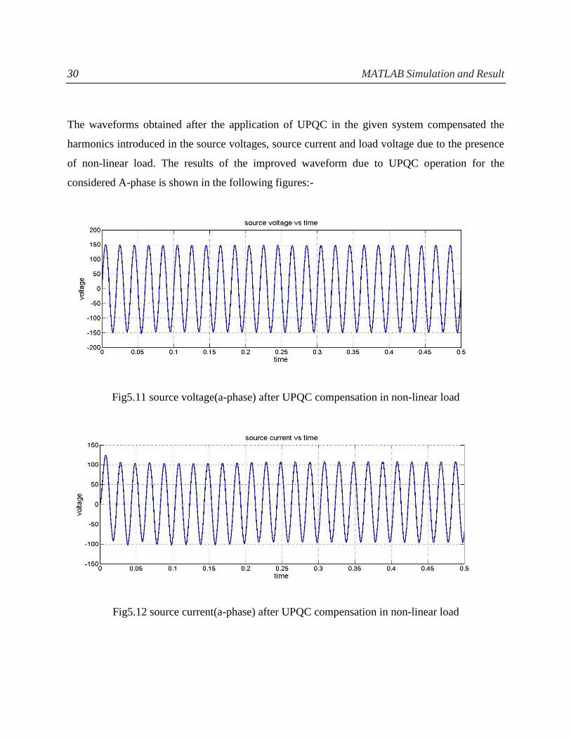
The waveforms obtained after the application of UPQC in the given system compensated the
harmonics introduced in the source voltages, source current and load voltage due to the presence
of non-linear load. The results of the improved waveform due to UPQC operation for the
considered A-phase is shown in the following figures:-
Fig5.11 source voltage(a-phase) after UPQC compensation in non-linear load
Fig5.12 source current(a-phase) after UPQC compensation in non-linear load

31 MATLAB Simulation and Result
Fig5.13 Load voltage(a-phase) after UPQC compensation in non-linear load
Fig5.14: Load current(a-phase) after UPQC compensation in non-linear load
Fig: DC link voltage across capacitor

32 MATLAB Simulation and Result
Result Of THD in Every Phase :-
THD before Compensation THD after Compensation
Source voltage A-phase
B-phase
C-phase
9.36%
9.16%
7.85%
2.23%
2.33%
2.33%
Source current A-phase
B-phase
C-phase
25.68%
25.78%
25.71%
3.57%
3.43%
3.63%
Load voltage A-phase
B-phase
C-phase
13.53%
13.24%
11.37%
4.05%
4.10%
4.13%
Table 5.2 Comparison of THD before and after UPQC application

33 Conclusion & Future Work
CONCLUSION
This thesis describes an improved control strategy for the operation of UPQC system. Several
control strategy is studied like p-q theory, SRF based approach, unit vector template generation
for the APF operation. The UPQC model is simulated in MATLAB using instantaneous power
theory. Shunt part of UPQC removes all the current related harmonic problems in the system and
series connected APF of UPQC system removes all voltage harmonics which comes up due to the
use of nonlinear load. The overall THD is now improved in the system which is clearly observed
from the waveforms and also from Table 5.2 giving the resultant THD before and after UPQC
operation.
FUTURE WORK
Preventing the harmonics due to presence of nonlinear load is difficult but its controlling is
possible and many research work is still going on for the same. Sliding Mode(SM) and feedback
linearization strategy of control is an advanced method for the operation of UPQC due to their ease
in implementation and robust in external disturbance. Further dSPACE software which is a good
interface between real time hardware and computer, it can be used to implement UPQC model
using a further new strategy called Fuzzy control method
34 References
REFERENCES
[1] D. C. Bhonsle, R. B. Kelkar, “Design and Simulation of Single Phase Shunt Active Power
Filter”, 2011 International Conference on Recent Advancements in Electrical, Electronics and
Control Engineering.
[2] V. Khadkikar, P. Aganval, A. Chandra, “ A Simple New Control Technique For Unified Power
Quality Conditioner (UPQC)”, 2004 11th International Conference on Harmonics and Quality of
Power.
[3] H. Akagi, Y. Kanazawa, A. Nabae , “Generalized Theory of the Instantaneous Reactive Power
in Three Phase Circuits”, in Proc. IPEC-Tokyo’83 Int. Conf. Power Electronics, Tokyo, pp. 1375-
1386.
[4] M.Kesler,E.Ozdemir,Senior Member, “Synchronous-Reference-Frame-Based Control Method
for UPQC under unbalanced and distorted load conditions”, IEEE transactions on industrial
electronics, vol. 58, no. 9, september 2011.
[5] I.Axente, M.Basu and M.Conlon, “dc link voltage control of UPQC for better dynamic
performance”, Electric Power Systems Research 81 (2011) 1815–1824.
[6] Yash Pal, A. Swarup, Bhim Singh, “A control strategy based on UTT and Icosɸ theory of three-
phase, four wire UPQC for power quality improvement ” International Journal of Engineering,
Science and Technology Vol. 3, No. 1, 2011, pp. 30-40.
[7] S.Shankar, A.Kumar and W.Gao “Operation of Unified Power Quality Conditioner under
Different Situation,” IEEE Proc. Power and Energy Society General Meeting, July 2011, pp.1-10.
[8] M.Basu, M.Das and S. Dubey, “Comparative evaluation of two models of UPQC for suitable
interface to enhance power quality,” Electric Power Systems Research, Vol. 77, no. 7, pp.821-830.
2007.
[9] Y. Kolhatkar and S. Das, “Experimental investigation of a single-phase UPQC with
minimum VA loading,” IEEE Trans. Power Del., vol. 22, no. 1, pp. 373–380, Jan. 2007.
35 References
[10] X. Zhang, W. Zhang, Y. Lv, W. Liu, and Q. Wang, “Unified power quality conditioner with
model predictive control,” in Proc. 5th Int. Conf. Comput. Sci. Educ., Aug. 24–27, 2010, pp. 1239–
1244.
[11] K. Vadirajacharya, P. Agarwal, and H. O. Gupta, “Unified constant frequency integration
control of universal power quality conditioner,” in Proc. Power Electron. Drive Energy Syst., Dec.
12–15, 2006, pp. 1–5.
[12] A.Banerji,S.K. Biswas,B. Singh,“DSTATCOM Control Algorithms: A Review,”International
Journal of Power Electronics and Drive System (IJPEDS), Vol.2, No.3, September 2012, pp. 285-
296.
[13] S. R. Naidu, A. W. Mascarenhas and D. A. Fernandes “A Software Phase-Locked Loop for
Unbalanced and Distorted Utility Conditions,” IEEE POWERCON Nov.2004,vol. 2, pp. 1055-
1060.
[14] C.Benachaiba, B.Ferdi ,“Voltage Quality Improvement Using DVR,” Electrical Power
Quality and Utilisation, Journal Vol. XIV, No. 1, 2008, pp.30-46.
[15] F. Kamran and T. G. Habetler, “Combined deadbeat control of a series parallel converter
combination used as a universal power filter,” in Proc. Power Electron. Spec. Conf., Jun. 18–22,
1995, pp. 196–201.