power quality improvement by upqc using different ... · pdf fileabstract ²unified power...
TRANSCRIPT
Abstract—Unified Power Quality Conditioner (UPQC) can
compensate voltage and/or current disturbances such as: Sags,
swell, unbalance voltage, harmonics and reactive power. UPQC
consists of combined series active power filter that compensates
voltage harmonics of the power supply, and shunt active power
filter that compensates harmonic currents of a non-linear load.
In this paper, we compare the effect of the different
defuzzification functions of the FIS Properties Editor on the
power quality improvement. The target controllers are located
in the current loop of the shunt active filter. The simulation
results in MATLAB/SIMULINK show that the defuzzification
function affects the behavior of the FLC and consequently the
compensation’s characteristic.
Index Terms—Shunt active filter, Series active filter, UPQC,
power quality, Sags voltage, THD
I. INTRODUCTION
DEAL power system is the power network which supplies a
pure-resistive equivalent load. The proliferation of
nonlinear loads results in the deterioration of the quality of
both the voltage waveforms at the point of common coupling
(PCC) and the current waveforms of the source side. Not
only the electronic devices, but the power system itself, like
the transformer, is the source of the harmonics. The power
quality problem is now cared by the power customer which
must be settled. Yet, due to the use of electric loads, it can
be very complex. Active filters have been known as the best
tool for harmonic mitigation as well as reactive power
compensation. They have been developed since 1983, when
one of the first prototypes based on instantaneous power
theory was reported [1] [2].
Many configurations such as shunt, series, hybrid (a
combination of shunt and series active filters), and unified
power quality conditioner (UPQC, a combination of series
and shunt active filters) have been introduced and improved
[3]. The UPQC can compensate not only harmonic currents
and unbalances of a non-linear load, but also voltage
harmonics and unbalances of the power sup-ply. The latter
improves the power quality offered for other harmonic
sensitive loads.
There are also different custom power devices such as
dynamic voltage restorer (DVR), which improves the quality
of power supply, distribution static compensator
(DSTATCOM), which compensates current unbalance and
C. Benachaiba is with Bechar University, Algeria (e-mail: chellali@
netscape.net).
B. Mazari is with USTOran, Algeria (e-mail: [email protected]).
M. Rahli is with USTOran, Algeria (e-mail: [email protected]).
harmonics of non-linear loads, and combined SVC with
DSTATCOM, which generates reactive power and
compensates load current simultaneously [4]–[6].
II. UNIFIED POWER QUALITY CONDITIONER
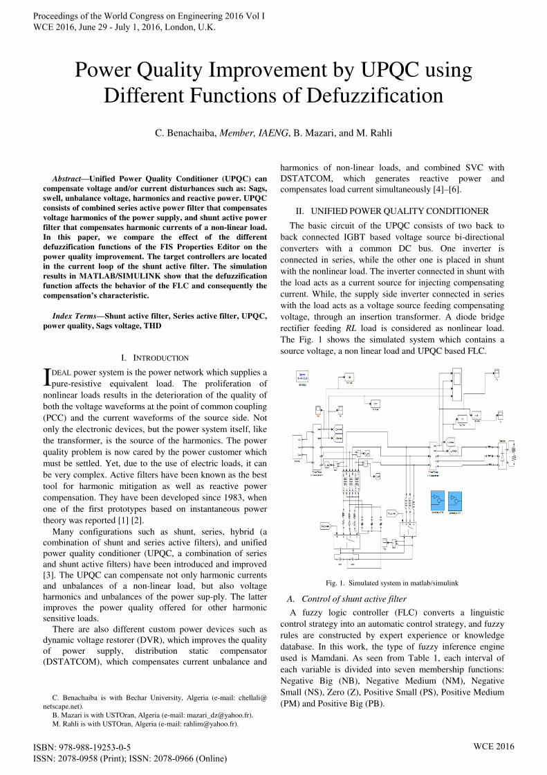
The basic circuit of the UPQC consists of two back to
back connected IGBT based voltage source bi-directional
converters with a common DC bus. One inverter is
connected in series, while the other one is placed in shunt
with the nonlinear load. The inverter connected in shunt with
the load acts as a current source for injecting compensating
current. While, the supply side inverter connected in series
with the load acts as a voltage source feeding compensating
voltage, through an insertion transformer. A diode bridge
rectifier feeding RL load is considered as nonlinear load.
The Fig. 1 shows the simulated system which contains a
source voltage, a non linear load and UPQC based FLC.
Fig. 1. Simulated system in matlab/simulink
A. Control of shunt active filter
A fuzzy logic controller (FLC) converts a linguistic
control strategy into an automatic control strategy, and fuzzy
rules are constructed by expert experience or knowledge
database. In this work, the type of fuzzy inference engine
used is Mamdani. As seen from Table 1, each interval of
each variable is divided into seven membership functions:
Negative Big (NB), Negative Medium (NM), Negative
Small (NS), Zero (Z), Positive Small (PS), Positive Medium
(PM) and Positive Big (PB).
Power Quality Improvement by UPQC using
Different Functions of Defuzzification
C. Benachaiba, Member, IAENG, B. Mazari, and M. Rahli
I
Proceedings of the World Congress on Engineering 2016 Vol I WCE 2016, June 29 - July 1, 2016, London, U.K.
ISBN: 978-988-19253-0-5 ISSN: 2078-0958 (Print); ISSN: 2078-0966 (Online)
WCE 2016

TABLE 1
DECISION TABLE OF FLC
u e
NB NM NS Z PS PM PB
PB Z PS PM PB PB PB PB
PM NS Z PS PM PB PB PB
e PS NM NS Z PS PM PB PB
Z NB NM NS Z PS PM PB
NS NB NB NM NS Z PS PM
NM NB NB NB NM NS Z PS
NB NB NB NB NB NM NS Z
Fig. 2 shows the FLC’s subsystem which has two inputs, the first one is the reference’s harmonic currents and the second is the measured harmonic current. The PQ theory is
adopted as control’s algorithm.
Fig. 2. Control of shunt active filter
Fig. 3 represents the implementation of the FLCs which
are based on the error and the error’s variation as inputs.
Fig.3. Fuzzy logic controller of Shunt active filter
The injected harmonic current for each phase is compared
to its reference current. The error and error’s variation are
the input variables. The three FLC which control each phase
are identical. The main objective of this work is to notice the
behavior for these three FLC when we change the
defuzzification function through the THD value of both
voltage and current.
B. Description of FLC’s parameters
FIS Editor opens and displays a diagram of the fuzzy
inference system with the names of each input and output
variables.
Fig. 4. FIS editor properties
Five pop-up menus are provided to change the
functionality of the five basic steps in the fuzzy implication
process:
• And method: Choose min, prod, or Custom, for a custom
operation.
Min: It resolves the statement A AND B, where A
and B are limited to the range (0,1), by using the
function min(A,B).
Prod: It scales the output fuzzy set.
• Or method: Choose max, probor (probabilistic or), or
Custom, for a custom operation.
Max: It resolves the statement A OR B, where A
and B are limited to the range (0,1), by using the
function max(A,B).
Probor: Probabilistic OR, y = probor(x) returns the
probabilistic OR (also known as the algebraic sum)
of the columns of x. if x has two rows such that x =
[a; b], then y = a + b - ab. If x has only one row,
then y = x.
• Implication: Choose min, prod, or Custom, for a custom
operation.
• Aggregation: Choose max, sum, probor, or Custom, for a
custom operation.
Sum: Simply the sum of each rule’s output set. • Defuzzification: For Mamdani-style inference, choose
centroid, bisector, mom, som, lom, or Custom, for a custom
operation.
Centroid: Centroid defuzzification returns the
center of area under the curve. If you think of the
area as a plate of equal density, the centroid is the
point along the x axis about which this shape would
balance.
Bisector: The bisector is the vertical line that will
divide the region into two sub-regions of equal
area. It is sometimes, but not always coincident
with the centroid line.
Mom: middle of maximum (the average of the
maximum value of the output set).
Proceedings of the World Congress on Engineering 2016 Vol I WCE 2016, June 29 - July 1, 2016, London, U.K.
ISBN: 978-988-19253-0-5 ISSN: 2078-0958 (Print); ISSN: 2078-0966 (Online)
WCE 2016
Som: Smallest of maximum (the smallest of the
maximum value of the output set).
Lom: Largest of maximum (the largest of the
maximum value of the output set).
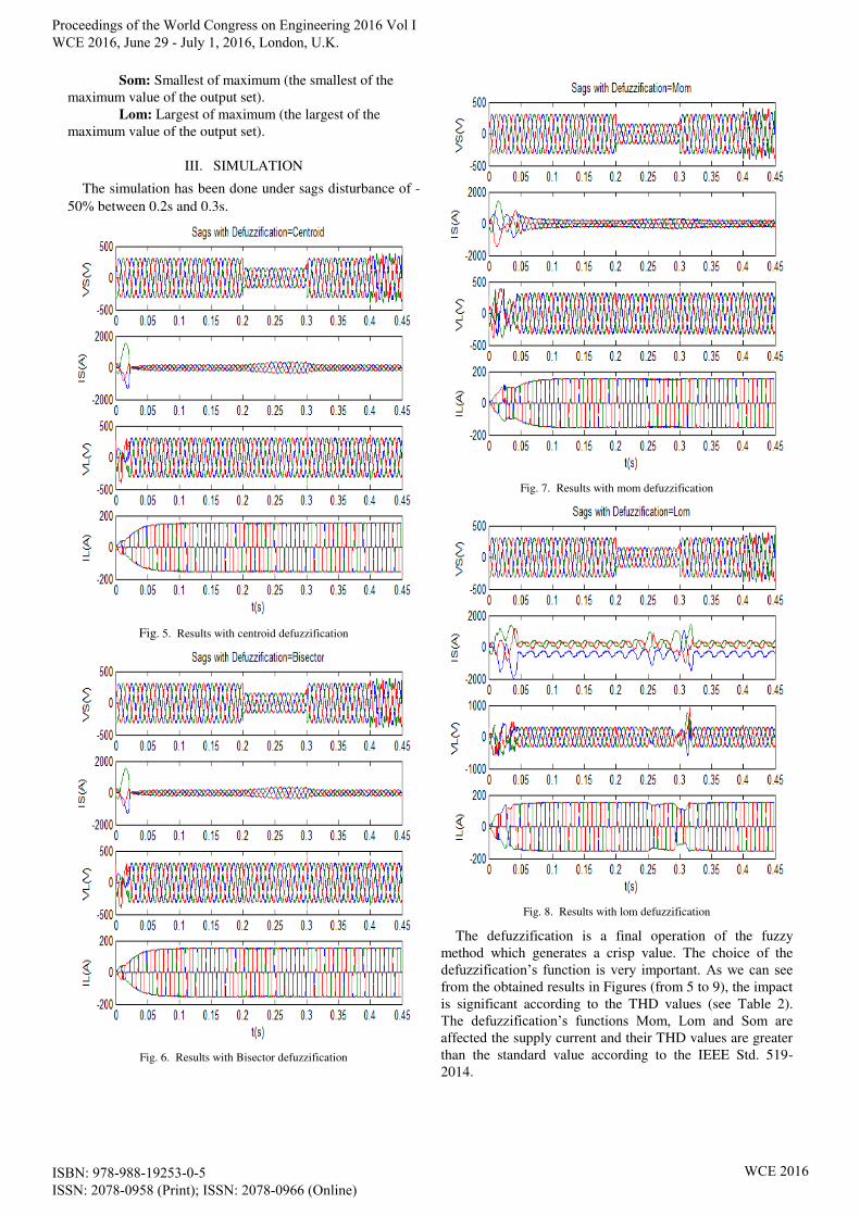
III. SIMULATION
The simulation has been done under sags disturbance of -
50% between 0.2s and 0.3s.
Fig. 5. Results with centroid defuzzification
Fig. 6. Results with Bisector defuzzification
Fig. 7. Results with mom defuzzification
Fig. 8. Results with lom defuzzification
The defuzzification is a final operation of the fuzzy
method which generates a crisp value. The choice of the
defuzzification’s function is very important. As we can see from the obtained results in Figures (from 5 to 9), the impact
is significant according to the THD values (see Table 2).
The defuzzification’s functions Mom, Lom and Som are affected the supply current and their THD values are greater
than the standard value according to the IEEE Std. 519-
2014.
Proceedings of the World Congress on Engineering 2016 Vol I WCE 2016, June 29 - July 1, 2016, London, U.K.
ISBN: 978-988-19253-0-5 ISSN: 2078-0958 (Print); ISSN: 2078-0966 (Online)
WCE 2016

Fig. 9. Results with som defuzzification
The table 2 below gives the THD values for both voltage
and current for different defuzzification’s functions
TABLE 2
THD VALUES
Defuz. Vsource Isource VLoad ILoad
Centroid 3.59% 2.06% 0.53% 26.83%
Bisector 3.59% 2.06% 0.53% 26.83%
Mom 3.66% 25.56% 0.57% 26.77%
Lom 3.59% 14.67% 5.73% 25.75%
Som 3.66% 25.56% 0.57% 26.77%
IV. CONCLUSION
The fuzzy logic is an intelligent method which is more
adapted for the non linear systems. The efficiency of the
FLC depends strongly at each step of both the form and
number of the membership functions, rules, and the weight
which is always equal to unit in the majority of papers
which, in contrast, could influence the results. The
defuzzification is a final operation that determines the
efficiency of the FLC, and its choice is very important. The
centroid and the bisector have given better THD value than
other defuzzifications’ methods.
REFERENCES
[1] B. Singh, K. Al-Haddad, and A. Chandra, “A review of active filters
for power quality improvement,” IEEE Transactions on Industrial
Electronics, vol. 46, Issue: 5, pp.960–97, Oct. 1999.
[2] L.A. Moran, I Pastorini, J. Dixon, and R Wallace, “A fault protection
scheme for series active power filters,” IEEE Transactions on Power
Electronics, vol. 14, Issue: 5, pp.928–938, Sept. 1999.
[3] Shu Hongchun, Liang Zuquan, Yu Jilai and Xu Liang, “A Novel
Control Strategy for UPQC,” IEEE/PES Transmission and
Distribution Conference & Exhibition: Asia and Pacific Dalian, pp.
1–4, China, 2005.
[4] C. Benachaiba, O. Abdelkhalek, S. Dib, M. Haidas, “Optimization of
parameters of the unified power quality conditioner using genetic
algorithm method,” Information Technology and Control, vol.36,
No.2, pp. 242–245, 2007.
[5] O. Abdelkhalek, C. Benachaiba, B. Gasbaoui, A. Nasri, “Using of
Anfis and fis methods to improve the UPQC performance, ” International Journal of Engineering Science and Technology, vol.
2(12), pp.6889-6901, 2010.
[6] C. Benachaiba, Ahmed M. A. Haidar, M. Habab, O. Abdelkhalek,
“Smart Control of UPCQ within Micro grid Energy System,”
ELSEVIER, Procedia Energy, vol. 6, pp. 503–512, 2011.
Proceedings of the World Congress on Engineering 2016 Vol I WCE 2016, June 29 - July 1, 2016, London, U.K.
ISBN: 978-988-19253-0-5 ISSN: 2078-0958 (Print); ISSN: 2078-0966 (Online)
WCE 2016