uas hangar - fy15 - fort carson, colorado fcw9 section ... · uas hangar - fy15 - fort carson,...
TRANSCRIPT

UAS Hangar - FY15 - Fort Carson, Colorado FCW9
SECTION TABLE OF CONTENTS
DIVISION 31 - EARTHWORK
SECTION 31 00 00
EARTHWORK
08/08
PART 1 GENERAL
1.1 CRITERIA FOR BIDDING 1.2 REFERENCES 1.3 DEFINITIONS 1.3.1 Satisfactory Materials 1.3.2 Unsatisfactory Materials 1.3.3 Cohesionless and Cohesive Materials 1.3.4 Degree of Compaction 1.3.5 Topsoil 1.3.6 Hard/Unyielding Materials 1.3.7 Rock 1.3.8 Unstable Material 1.3.9 Select Granular Material 1.3.9.1 General Requirements 1.3.10 Initial Backfill Material 1.3.11 Expansive Soils 1.3.12 Nonfrost Susceptible (NFS) Material 1.4 SYSTEM DESCRIPTION 1.4.1 Classification of Excavation 1.4.1.1 Common Excavation 1.4.2 Dewatering Work Plan 1.5 SUBMITTALS
PART 2 PRODUCTS
2.1 REQUIREMENTS FOR OFFSITE SOILS 2.2 BURIED WARNING AND IDENTIFICATION TAPE 2.2.1 Warning Tape for Metallic Piping 2.2.2 Detectable Warning Tape for Non-Metallic Piping 2.3 DETECTION WIRE FOR NON-METALLIC PIPING 2.4 MATERIAL FOR RIP-RAP 2.4.1 Bedding Material 2.4.2 Rock 2.5 CAPILLARY WATER BARRIER
PART 3 EXECUTION
3.1 STRIPPING OF TOPSOIL 3.2 GENERAL EXCAVATION 3.2.1 Ditches, Gutters, and Channel Changes 3.2.2 Drainage Structures 3.2.3 Drainage 3.2.4 Dewatering 3.2.5 Trench Excavation Requirements 3.2.5.1 Bottom Preparation
SECTION 31 00 00 Page 1

UAS Hangar - FY15 - Fort Carson, Colorado FCW9
3.2.5.2 Removal of Unyielding Material 3.2.5.3 Removal of Unstable Material 3.2.5.4 Excavation for Appurtenances 3.2.5.5 Jacking, Boring, and Tunneling 3.2.6 Underground Utilities 3.2.7 Structural Excavation 3.3 SELECTION OF BORROW MATERIAL 3.4 OPENING AND DRAINAGE OF EXCAVATION AND BORROW PITS 3.5 SHORING 3.5.1 General Requirements 3.6 GRADING AREAS 3.7 FINAL GRADE OF SURFACES TO SUPPORT CONCRETE 3.8 GROUND SURFACE PREPARATION 3.8.1 General Requirements 3.8.2 Frozen Material 3.9 UTILIZATION OF EXCAVATED MATERIALS 3.10 BURIED TAPE AND TRACER WIRE 3.10.1 Buried Warning and Identification Tape 3.10.2 Tracer Wire and Tracer Wire Test Stations 3.11 BACKFILLING AND COMPACTION 3.11.1 Trench Backfill 3.11.1.1 Replacement of Unyielding Material 3.11.1.2 Replacement of Unstable Material 3.11.1.3 Bedding and Initial Backfill 3.11.1.3.1 Class I 3.11.1.3.2 Class II 3.11.1.4 Final Backfill 3.11.1.4.1 Roadways and Airfields 3.11.1.4.2 Sidewalks, Turfed or Seeded Areas and Miscellaneous
Areas 3.11.2 Backfill for Appurtenances 3.12 SPECIAL REQUIREMENTS 3.12.1 Gas Distribution 3.12.2 Water Lines 3.12.3 Heat Distribution System 3.12.4 Electrical Distribution System 3.12.5 Rip-Rap Construction 3.12.5.1 Bedding Placement 3.12.5.2 Stone Placement 3.13 EMBANKMENTS 3.13.1 Earth Embankments 3.14 SUBGRADE PREPARATION 3.14.1 Construction 3.14.2 Compaction 3.14.2.1 Subgrade for Pavements 3.14.2.2 Subgrade for Shoulders 3.14.2.3 Subgrade for Airfield Pavements 3.15 SHOULDER CONSTRUCTION 3.16 FINISHING 3.16.1 Subgrade and Embankments 3.16.2 Grading Around Structures 3.17 PLACING TOPSOIL 3.18 TESTING 3.18.1 Fill and Backfill Material Gradation 3.18.2 In-Place Densities 3.18.3 Check Tests on In-Place Densities 3.18.4 Moisture Contents 3.18.5 Optimum Moisture and Laboratory Maximum Density 3.18.6 Tolerance Tests for Subgrades
SECTION 31 00 00 Page 2

UAS Hangar - FY15 - Fort Carson, Colorado FCW9
3.18.7 Displacement of Sewers 3.19 DISPOSITION OF SURPLUS MATERIAL
-- End of Section Table of Contents --
SECTION 31 00 00 Page 3

UAS Hangar - FY15 - Fort Carson, Colorado FCW9
SECTION 31 00 00
EARTHWORK08/08
PART 1 GENERAL
1.1 CRITERIA FOR BIDDING
Base bids on the following criteria:
a. Surface elevations are as indicated.
b. Pipes or other artificial obstructions, except those indicated, will not be encountered.
c. Ground water elevations indicated on the boring logs were those existing at the time subsurface investigations were made and do not necessarily represent ground water elevation at the time of construction. Reference the attached Final Geotechnical Report, UAS Hangar, dated 3 June 2014 (Rev 18 December 2014), for more information.
d. Material character is indicated on the boring logs. Reference the attached Final Geotechnical Report, UAS Hangar, dated 3 June 2014 (Rev 18 December 2014), for more information.
e. Hard materialswill be encountered where indicated on the boring logs. Reference the attached Final Geotechnical Report, UAS Hangar, dated 3 June 2014 (Rev 18 December 2014), for more information.
1.2 REFERENCES
The publications listed below form a part of this specification to the extent referenced. The publications are referred to within the text by the basic designation only.
AMERICAN ASSOCIATION OF STATE HIGHWAY AND TRANSPORTATION OFFICIALS (AASHTO)
AASHTO T 180 (2010) Standard Method of Test for Moisture-Density Relations of Soils Using a 4.54-kg (10-lb) Rammer and a 457-mm (18-in.) Drop
AASHTO T 224 (2010) Standard Method of Test for Correction for Coarse Particles in the Soil Compaction Test
AMERICAN WATER WORKS ASSOCIATION (AWWA)
AWWA C600 (2010) Installation of Ductile-Iron Water Mains and Their Appurtenances
AMERICAN WELDING SOCIETY (AWS)
AWS D1.1/D1.1M (2010; Errata 2011) Structural Welding
SECTION 31 00 00 Page 4

UAS Hangar - FY15 - Fort Carson, Colorado FCW9
Code - Steel
AMERICAN WOOD PROTECTION ASSOCIATION (AWPA)
AWPA C2 (2003) Lumber, Timber, Bridge Ties and Mine Ties - Preservative Treatment by Pressure Processes
AWPA P5 (2007) Standard for Waterborne Preservatives
ASTM INTERNATIONAL (ASTM)
ASTM A139/A139M (2004; R 2010) Standard Specification for Electric-Fusion (ARC)-Welded Steel Pipe (NPS 4 and over)
ASTM A252 (2010) Standard Specification for Welded and Seamless Steel Pipe Piles
ASTM C136 (2006) Standard Test Method for Sieve Analysis of Fine and Coarse Aggregates
ASTM C33/C33M (2013) Standard Specification for Concrete Aggregates
ASTM D1140 (2000; R 2006) Amount of Material in Soils Finer than the No. 200 (75-micrometer) Sieve
ASTM D1556 (2007) Density and Unit Weight of Soil in Place by the Sand-Cone Method
ASTM D1557 (2012) Standard Test Methods for Laboratory Compaction Characteristics of Soil Using Modified Effort (56,000 ft-lbf/ft3) (2700 kN-m/m3)
ASTM D1883 (2007; E 2009; E 2009) CBR (California Bearing Ratio) of Laboratory-Compacted Soils
ASTM D2167 (2008) Density and Unit Weight of Soil in Place by the Rubber Balloon Method
ASTM D2434 (1968; R 2006) Permeability of Granular Soils (Constant Head)
ASTM D2487 (2011) Soils for Engineering Purposes (Unified Soil Classification System)
ASTM D2937 (2010) Density of Soil in Place by the Drive-Cylinder Method
ASTM D422 (1963; R 2007; E 2014) Particle-Size Analysis of Soils
ASTM D4318 (2010; E 2014) Liquid Limit, Plastic Limit, and Plasticity Index of Soils
SECTION 31 00 00 Page 5

UAS Hangar - FY15 - Fort Carson, Colorado FCW9
ASTM D6938 (2010) Standard Test Method for In-Place Density and Water Content of Soil and Soil-Aggregate by Nuclear Methods (Shallow Depth)
ASTM D698 (2012; E 2014) Laboratory Compaction Characteristics of Soil Using Standard Effort (12,400 ft-lbf/cu. ft. (600 kN-m/cu. m.))
U.S. ARMY CORPS OF ENGINEERS (USACE)
EM 385-1-1 (2008; Errata 1-2010; Changes 1-3 2010; Changes 4-6 2011; Change 7 2012) Safety and Health Requirements Manual
U.S. ENVIRONMENTAL PROTECTION AGENCY (EPA)
EPA 600/4-79/020 (1983) Methods for Chemical Analysis of Water and Wastes
EPA SW-846.3-3 (1999, Third Edition, Update III-A) Test Methods for Evaluating Solid Waste: Physical/Chemical Methods
U.S. GENERAL SERVICES ADMINISTRATION (GSA)
CID A-A-203 (Rev C; Notice 3) Paper, Kraft, Untreated
1.3 DEFINITIONS
1.3.1 Satisfactory Materials
Satisfactory materials comprise any materials classified by ASTM D2487 as GW, GP, GM, GP-GM, GW-GM, GC, GP-GC, GM-GC, SW, SP, SM, SW-SM, SC, SW-SC, SP-SM, SP-SC, and CL meeting the requirements contained within Section 7.1 Description and Placement of Fill of the attached Final Geotechnical Report, UAS Hangar, dated 3 June 2014 (Rev 18 December 2014). For CL material, the requirements for Liquid Limit and Plasticity Index contained within Section 7.1 Description and Placement of Fill of the attached Final Geotechnical Report, UAS Hangar, dated 3 June 2014 (Rev 18 December 2014) shall be adhered to. Satisfactory materials for grading comprise stones less than 4 inches.
1.3.2 Unsatisfactory Materials
Materials which do not comply with the requirements for satisfactory materials are unsatisfactory. Unsatisfactory materials also include trash; refuse; and material classified as satisfactory which contains root and other organic matter or frozen material. Notify the Contracting Officer when encountering any contaminated materials.
1.3.3 Cohesionless and Cohesive Materials
Cohesionless materials include materials classified in ASTM D2487 as GW, GP, SW, and SP. Cohesive materials include materials classified as GC, SC, ML, CL, MH, and CH. Materials classified as GM and SM will be identified as cohesionless only when the fines are nonplastic. Perform testing,
SECTION 31 00 00 Page 6

UAS Hangar - FY15 - Fort Carson, Colorado FCW9
required for classifying materials, in accordance with ASTM D4318, ASTM C136, ASTM D422, and ASTM D1140.
1.3.4 Degree of Compaction
Degree of compaction required, except as noted in the second sentence, is expressed as a percentage of the maximum density obtained by the test procedure presented in ASTM D1557 abbreviated as a percent of laboratory maximum density. Since ASTM D1557 applies only to soils that have 30 percent or less by weight of their particles retained on the 3/4 inch sieve, express the degree of compaction for material having more than 30 percent by weight of their particles retained on the 3/4 inch sieve as a percentage of the maximum density in accordance with AASHTO T 180 and corrected with AASHTO T 224. To maintain the same percentage of coarse material, use the "remove and replace" procedure as described in NOTE 8 of Paragraph 7.2 in AASHTO T 180.
1.3.5 Topsoil
See specification Section 32 92 19 SEEDING for definition of acceptable topsoil.
1.3.6 Hard/Unyielding Materials
Hard/Unyielding materials comprise weathered rock, dense consolidated deposits, or conglomerate materials which are not included in the definition of "rock" with stones greater than 3 inches in any dimension or as defined by the pipe manufacturer, whichever is smaller. These materials usually require the use of heavy excavation equipment, ripper teeth, or jack hammers for removal.
1.3.7 Rock
Solid homogeneous interlocking crystalline material with firmly cemented, laminated, or foliated masses or conglomerate deposits, neither of which can be removed without systematic drilling and blasting, drilling and the use of expansion jacks or feather wedges, or the use of backhoe-mounted pneumatic hole punchers or rock breakers; also large boulders, buried masonry, or concrete other than pavement exceeding 1/2 cubic yard in volume.
1.3.8 Unstable Material
Unstable materials are too wet to properly support the utility pipe, conduit, or appurtenant structure.
1.3.9 Select Granular Material
1.3.9.1 General Requirements
Select granular material consist of materials classified as GW, SW, GW-SM or SW-SM by ASTM D2487 where indicated. The liquid limit of such material must not exceed 21 percent when tested in accordance with ASTM D4318. The plasticity index must not be greater than 12 percent when tested in accordance with ASTM D4318, and not more than 35percent by weight may be finer than No. 200 sieve when tested in accordance with ASTM D 1140.
1.3.10 Initial Backfill Material
Initial backfill consists of satisfactory materials free from rocks 1/2
SECTION 31 00 00 Page 7

UAS Hangar - FY15 - Fort Carson, Colorado FCW9
inches or larger in any dimension or free from rocks of such size as recommended by the pipe manufacturer, whichever is smaller. Material locally referred to as "Pea Gravel" shall not be used.
1.3.11 Expansive Soils
Expansive soils are defined as soils that have a plasticity index equal to or greater than 21 when tested in accordance with ASTM D4318.
1.3.12 Nonfrost Susceptible (NFS) Material
Nonfrost susceptible material are a uniformly graded washed sand with a maximum particle size of 1-inch and less than 5 percent passing the No. 200 size sieve, and with not more than 3 percent by weight finer than 0.02 mm grain size.
1.4 SYSTEM DESCRIPTION
Subsurface soil boring logs are provided within the attached Final Geotechnical Report, UAS Hangar, dated 3 June 2014 (Rev 18 December 2014). These data represent the best subsurface information available; however, variations may exist in the subsurface between boring locations.
1.4.1 Classification of Excavation
No consideration will be given to the nature of the materials, and all excavation will be designated as unclassified excavation.
1.4.1.1 Common Excavation
Include common excavation with the satisfactory removal and disposal of all materials not classified as rock excavation.
1.4.2 Dewatering Work Plan
Submit procedures for accomplishing dewatering work.
1.5 SUBMITTALS
Government approval is required for submittals with a "G" designation; submittals not having a "G" designation are for information only. When used, a designation following the "G" designation identifies the office that will review the submittal for the Government. Submit the following in accordance with Section 01 33 00 SUBMITTAL PROCEDURES:
SD-01 Preconstruction Submittals
Shoring; G, PODewatering Work Plan; G, POSubmit 15 days prior to starting work.
SD-03 Product Data
Utilization of Excavated Materials; G, POProcedure and location for disposal of unused satisfactory material. Proposed source of borrow material. Notification of encountering rock in the project. Advance notice on the opening of excavation or borrow areas.
SECTION 31 00 00 Page 8

UAS Hangar - FY15 - Fort Carson, Colorado FCW9
SD-06 Test Reports
Testing; G, POBorrow Site Testing;
Within 24 hours of conclusion of physical tests, submit 2 copies of test results, including calibration curves and results of calibration tests. Results of testing at the borrow.
SD-07 Certificates
Testing; G, PO
Qualifications of the Corps validated commercial testing laboratory of the Contractor's validated testing facilities.
PART 2 PRODUCTS
2.1 REQUIREMENTS FOR OFFSITE SOILS
Contaminated materials shall not be brought to the site.
2.2 BURIED WARNING AND IDENTIFICATION TAPE
Provide polyethylene plastic and metallic core or metallic-faced, acid- and alkali-resistant, polyethylene plastic warning tape manufactured specifically for warning and identification of buried utility lines. Provide tape on rolls, 3 inches minimum width, color coded as specified below for the intended utility with warning and identification imprinted in bold black letters continuously over the entire tape length. Warning and identification to read, "CAUTION, BURIED (intended service) LINE BELOW" or similar wording. Provide permanent color and printing, unaffected by moisture or soil.
Warning Tape Color Codes
Red Electric
Yellow Gas, Oil; Dangerous Materials
Orange Telephone and Other Communications
Blue Water Systems
Green Sewer Systems
White Steam Systems
Gray Compressed Air
2.2.1 Warning Tape for Metallic Piping
Provide acid and alkali-resistant polyethylene plastic tape conforming to the width, color, and printing requirements specified above, with a minimum thickness of 0.003 inch and a minimum strength of 1500 psi lengthwise, and 1250 psi crosswise, with a maximum 350 percent elongation.
SECTION 31 00 00 Page 9
UAS Hangar - FY15 - Fort Carson, Colorado FCW9
2.2.2 Detectable Warning Tape for Non-Metallic Piping
Provide polyethylene plastic tape conforming to the width, color, and printing requirements specified above, with a minimum thickness of 0.004 inch, and a minimum strength of 1500 psi lengthwise and 1250 psi crosswise. Manufacture tape with integral wires, foil backing, or other means of enabling detection by a metal detector when tape is buried up to 3 feet deep. Encase metallic element of the tape in a protective jacket or provide with other means of corrosion protection.
2.3 DETECTION WIRE FOR NON-METALLIC PIPING
Provide detection wire (utility tracer wire) of sufficient length to be continuous over each separate run of nonmetallic pipe.
For gas lines, use #6 AWG type TW, RHW, RHW-2, THHW, THW, XHHW-2 or HMWPE (wet locations) stranded or solid copper, colored yellow.
For all other utilities, use #12 AWG type TW, RHW, RHW-2, THHW, THW, XHHW-2 or HMWPE (wet locations) solid copper, wire color to match warning tape color, placed on top of the utility.
2.4 MATERIAL FOR RIP-RAP
Provide bedding material and rock conforming to Colorado DOT State Standard for construction indicated.
2.4.1 Bedding Material
Provide bedding material consisting of sand, gravel, or crushed rock, well graded, with a maximum particle size of 2 inches. Compose material of tough, durable particles. Allow fines passing the No. 200 standard sieve with a plasticity index less than six.
2.4.2 Rock
Provide rock fragments sufficiently durable to ensure permanence in the structure and the environment in which it is to be used. Use rock fragments free from cracks, seams, and other defects that would increase the risk of deterioration from natural causes. Provide fragments sized as shown on the plans. Provide rock with a minimum specific gravity of 2.50. Do not permit the inclusion of more than trace, 1 percent quantities of dirt, sand, clay, and rock fines.
2.5 CAPILLARY WATER BARRIER
Provide capillary water barrier of clean, poorly graded crushed rock, crushed gravel, or uncrushed gravel placed beneath a building slab with or without a vapor barrier to cut off the capillary flow of pore water to the area immediately below. Conform to ASTM C33/C33M for fine aggregate grading with a maximum of 3 percent by weight passing ASTM D1140, No. 200 sieve, or 1-1/2 inch sieve and no more than 2 percent by weight passing the No. 4 size sieve.
SECTION 31 00 00 Page 10

UAS Hangar - FY15 - Fort Carson, Colorado FCW9
PART 3 EXECUTION
3.1 STRIPPING OF TOPSOIL
Where indicated or directed, strip topsoil to a depth of 6 inches. Spread topsoil on areas already graded and prepared for topsoil, or transported and deposited in stockpiles convenient to areas that are to receive application of the topsoil later, or at locations indicated or specified. Keep topsoil separate from other excavated materials, brush, litter, objectionable weeds, roots, stones larger than 1-inch in diameter, and other materials that would interfere with planting and maintenance operations. Remove from the site any surplus of topsoil from excavations and gradings.
3.2 GENERAL EXCAVATION
Perform excavation of every type of material encountered within the limits of the project to the lines, grades, and elevations indicated and as specified. Perform the grading in accordance with the typical sections shown and the tolerances specified in paragraph FINISHING. Transport satisfactory excavated materials and place in fill or embankment within the limits of the work. Excavate unsatisfactory materials encountered within the limits of the work below grade and replace with satisfactory materials as directed. Include such excavated material and the satisfactory material ordered as replacement in excavation. Dispose surplus satisfactory excavated material not required for fill or embankment in areas approved for surplus material storage or designated waste areas. Dispose unsatisfactory excavated material in designated waste or spoil areas. During construction, perform excavation and fill in a manner and sequence that will provide proper drainage at all times. Excavate material required for fill or embankment in excess of that produced by excavation within the grading limits from the borrow areas indicated or from other approved areas selected by the Contractor as specified.
3.2.1 Ditches, Gutters, and Channel Changes
Finish excavation of ditches, gutters, and channel changes by cutting accurately to the cross sections, grades, and elevations shown on the drawings. Do not excavate ditches and gutters below grades shown. Backfill the excessive open ditch or gutter excavation with satisfactory, thoroughly compacted, material or with suitable stone or cobble to grades shown. Dispose excavated material as shown or as directed, except in no case allow material be deposited a maximum 4 feet from edge of a ditch. Maintain excavations free from detrimental quantities of leaves, brush, sticks, trash, and other debris until final acceptance of the work.
3.2.2 Drainage Structures
Make excavations to the lines, grades, and elevations shown, or as directed. Provide trenches and foundation pits of sufficient size to permit the placement and removal of forms for the full length and width of structure footings and foundations as shown. Do not disturb the bottom of the excavation when concrete or masonry is to be placed in an excavated area. Do not excavate to the final grade level until just before the concrete or masonry is to be placed.
3.2.3 Drainage
Provide for the collection and disposal of surface and subsurface water
SECTION 31 00 00 Page 11

UAS Hangar - FY15 - Fort Carson, Colorado FCW9
encountered during construction. Completely drain construction site during periods of construction to keep soil materials sufficiently dry. Construct storm drainage features (ponds/basins) at the earliest stages of site development, and throughout construction grade the construction area to provide positive surface water runoff away from the construction activity or provide temporary ditches, swales, and other drainage features and equipment as required to maintain dry soils. When unsuitable working platforms for equipment operation and unsuitable soil support for subsequent construction features develop, remove unsuitable material and provide new soil material as specified herein. It is the responsibility of the Contractor to assess the soil and ground water conditions presented by the plans and specifications and to employ necessary measures to permit construction to proceed.
3.2.4 Dewatering
Control groundwater flowing toward or into excavations to prevent sloughing of excavation slopes and walls, boils, uplift and heave in the excavation and to eliminate interference with orderly progress of construction. Do not permit French drains, sumps, ditches or trenches within 3 feet of the foundation of any structure, except with specific written approval, and after specific contractual provisions for restoration of the foundation area have been made. Take control measures by the time the excavation reaches the water level in order to maintain the integrity of the in situ material.
3.2.5 Trench Excavation Requirements
Excavate the trench as recommended by the manufacturer of the pipe to be installed. Slope trench walls below the top of the pipe, or make vertical, and of such width as recommended in the manufacturer's printed installation manual. Provide vertical trench walls where no manufacturer's printed installation manual is available. Shore trench walls or provide other means of ensuring worker safety in accordance with 29 CFR 1926 and all other applicable Corps, State, Federal and Local safety regulations. Give special attention to slopes which may be adversely affected by weather or moisture content. Do not exceed the trench width below the pipe top of 24 inches plus pipe outside diameter (O.D.) for pipes of less than 24 inches inside diameter, and do not exceed 36 inches plus pipe outside diameter for sizes larger than 24 inches inside diameter. Where recommended trench widths are exceeded, provide redesign, stronger pipe, or special installation procedures by the Contractor. The Contractor is responsible for the cost of redesign, stronger pipe, or special installation procedures without any additional cost to the Government.
3.2.5.1 Bottom Preparation
Grade the bottoms of trenches accurately to provide uniform bearing and support for the bottom quadrant of each section of the pipe. Excavate bell holes to the necessary size at each joint or coupling to eliminate point bearing. Remove stones of 3 inches or greater in any dimension, or as recommended by the pipe manufacturer, whichever is smaller, to avoid point bearing.
3.2.5.2 Removal of Unyielding Material
Where unyielding material is encountered in the bottom of the trench, remove such material 4 inches below the required grade and replaced with suitable materials as provided in paragraph BACKFILLING AND COMPACTION.
SECTION 31 00 00 Page 12

UAS Hangar - FY15 - Fort Carson, Colorado FCW9
3.2.5.3 Removal of Unstable Material
Where unstable material is encountered in the bottom of the trench, remove such material to the depth directed and replace it to the proper grade with select granular material as provided in paragraph BACKFILLING AND COMPACTION. When removal of unstable material is required due to the Contractor's fault or neglect in performing the work, the Contractor is responsible for excavating the resulting material and replacing it without additional cost to the Government.
3.2.5.4 Excavation for Appurtenances
Provide excavation for manholes, catch-basins, inlets, or similar structures sufficient to leave at least 12 inches clear between the outer structure surfaces and the face of the excavation or support members. Specify removal of unstable material. When concrete or masonry is to be placed in an excavated area, take special care not to disturb the bottom of the excavation. Do not excavate to the final grade level until just before the concrete or masonry is to be placed.
3.2.5.5 Jacking, Boring, and Tunneling
Unless otherwise indicated, provide excavation by open cut except that sections of a trench may be jacked, bored, or tunneled if, in the opinion of the Contracting Officer, the pipe, cable, or duct can be safely and properly installed and backfill can be properly compacted in such sections.
3.2.6 Underground Utilities
The Contractor is responsible for movement of construction machinery and equipment over pipes and utilities during construction. Perform work adjacent to non-Government utilities as indicated in accordance with procedures outlined by utility company. Excavation made with power-driven equipment is not permitted within 2 feet of known Government-owned utility or subsurface construction. For work immediately adjacent to or for excavations exposing a utility or other buried obstruction, excavate by hand. Start hand excavation on each side of the indicated obstruction and continue until the obstruction is uncovered or until clearance for the new grade is assured. Support uncovered lines or other existing work affected by the contract excavation until approval for backfill is granted by the Contracting Officer. Report damage to utility lines or subsurface construction immediately to the Contracting Officer.
3.2.7 Structural Excavation
Ensure that footing subgrades have been inspected and approved by the Contracting Officer prior to concrete placement.
3.3 SELECTION OF BORROW MATERIAL
Select borrow material to meet the requirements and conditions of the particular fill or embankment for which it is to be used. Unless otherwise provided in the contract, the Contractor is responsible for obtaining the right to procure material, pay royalties and other charges involved, and bear the expense of developing the sources, including rights-of-way for hauling from the owners. Unless specifically provided, do not obtain borrow within the limits of the project site without prior written approval. Consider necessary clearing, grubbing, and satisfactory drainage
SECTION 31 00 00 Page 13

UAS Hangar - FY15 - Fort Carson, Colorado FCW9
of borrow pits and the disposal of debris thereon related operations to the borrow excavation.
3.4 OPENING AND DRAINAGE OF EXCAVATION AND BORROW PITS
Notify the Contracting Officer sufficiently in advance of the opening of any excavation or borrow pit or borrow areas to permit elevations and measurements of the undisturbed ground surface to be taken. Except as otherwise permitted, excavate borrow pits and other excavation areas providing adequate drainage. Transport overburden and other spoil material to designated spoil areas or otherwise dispose of as directed. Provide neatly trimmed and drained borrow pits after the excavation is completed. Ensure that excavation of any area, operation of borrow pits, or dumping of spoil material results in minimum detrimental effects on natural environmental conditions.
3.5 SHORING
3.5.1 General Requirements
Submit a Shoring and Sheeting plan for approval 15 days prior to starting work. Submit drawings and calculations, certified by a registered professional engineer, describing the methods for shoring and sheeting of excavations. Finish shoring, including sheet piling, and install as necessary to protect workmen, banks, adjacent paving, structures, and utilities. Remove shoring, bracing, and sheeting as excavations are backfilled, in a manner to prevent caving.
3.6 GRADING AREAS
Where indicated, divide work into grading areas within which satisfactory excavated material will be placed in embankments, fills, and required backfills. Do not haul satisfactory material excavated in one grading area to another grading area except when so directed in writing. Place and grade stockpiles of satisfactory and unsatisfactory and wasted materials as specified. Keep stockpiles in a neat and well drained condition, giving due consideration to drainage at all times. Clear, grub, and seal by rubber-tired equipment, the ground surface at stockpile locations; separately stockpile excavated satisfactory and unsatisfactory materials. Protect stockpiles of satisfactory materials from contamination which may destroy the quality and fitness of the stockpiled material. If the Contractor fails to protect the stockpiles, and any material becomes unsatisfactory, remove and replace such material with satisfactory material from approved sources.
3.7 FINAL GRADE OF SURFACES TO SUPPORT CONCRETE
Do not excavate to final grade until just before concrete is to be placed. Roughen the level surfaces, and cut the sloped surfaces, as indicated, into rough steps or benches to provide a satisfactory bond. Protect all surfaces from erosion resulting from ponding or water flow.
3.8 GROUND SURFACE PREPARATION
3.8.1 General Requirements
Remove and replace unsatisfactory material with satisfactory materials, as directed by the Contracting Officer, in surfaces to receive fill or in excavated areas. Scarify the surface to a depth of 6 inches before the
SECTION 31 00 00 Page 14
UAS Hangar - FY15 - Fort Carson, Colorado FCW9
fill is started. Plow, step, bench, or break up sloped surfaces steeper than 1 vertical to 4 horizontal so that the fill material will bond with the existing material. When subgrades are less than the specified density, break up the ground surface to a minimum depth of 6 inches, pulverizing, and compacting to the specified density. When the subgrade is part fill and part excavation or natural ground, scarify the excavated or natural ground portion to a depth of 12 inches and compact it as specified for the adjacent fill.
3.8.2 Frozen Material
Do not place material on surfaces that are muddy, frozen, or contain frost.
3.9 UTILIZATION OF EXCAVATED MATERIALS
Unsatisfactory materials removed from excavations shall be disposed off of Government property. Use satisfactory material removed from excavations, insofar as practicable, in the construction of fills, embankments, subgrades, shoulders, bedding, and for similar purposes. Do not waste any satisfactory excavated material without specific written authorization. Dispose of satisfactory material, authorized to be wasted, off of Government property. Do not dispose excavated material to obstruct the flow of any stream, endanger a partly finished structure, impair the efficiency or appearance of any structure, or be detrimental to the completed work in any way.
3.10 BURIED TAPE AND TRACER WIRE
3.10.1 Buried Warning and Identification Tape
Provide buried utility lines with utility identification tape. Bury tape 12 inches below finished grade; under pavements and slabs, bury tape 6 inches below top of subgrade.
3.10.2 Tracer Wire and Tracer Wire Test Stations
Tracer wire leads shall be brought up, identified, and protected by tracer wire test stations of the flush-curb-box type; H-20 rated, and shall be the standard product of a recognized manufacturer (HANDLEY or equal). Test stations shall have a cast iron lid and be mounted in 18 inches of concrete. Where possible, combine the Cathodic Test Station, Valve Box, and Tracer Wire Test Stations in the same concrete pad. Test stations shall not be placed further that 400-ft apart. Contractor shall coil 18-inches of extra wire into the test stations for maintenance. See standard details shown in drawing (Fort Carson Fort Carson Utility Tracer Wire Installation Details).
The contractor shall test the tracer wire for continuity in the presence of the Contracting Officer Representative. Any discontinuities in the wire shall be repaired.
3.11 BACKFILLING AND COMPACTION
Place backfill adjacent to any and all types of structures, and compact to at least 95 percent laboratory maximum density (ASTM D1557), to prevent wedging action or eccentric loading upon or against the structure. Prepare ground surface on which backfill is to be placed and provide compaction requirements for backfill materials in conformance with the applicable portions of paragraphs GROUND SURFACE PREPARATION. Finish compaction by
SECTION 31 00 00 Page 15

UAS Hangar - FY15 - Fort Carson, Colorado FCW9
sheepsfoot rollers, pneumatic-tired rollers, steel-wheeled rollers, vibratory compactors, or other approved equipment.
3.11.1 Trench Backfill
Backfill trenches to the grade shown. Backfill the trench to 2 feet above the top of pipe prior to performing the required pressure tests. Leave the joints and couplings uncovered during the pressure test.
3.11.1.1 Replacement of Unyielding Material
Replace unyielding material removed from the bottom of the trench with select granular material or initial backfill material.
3.11.1.2 Replacement of Unstable Material
Replace unstable material removed from the bottom of the trench or excavation with select granular material placed in layers not exceeding 6 inches loose thickness.
3.11.1.3 Bedding and Initial Backfill
Provide bedding of the type and thickness shown. Place initial backfill material and compact it with approved tampers to a height of at least one foot above the utility pipe or conduit. Bring up the backfill evenly on both sides of the pipe for the full length of the pipe. Take care to ensure thorough compaction of the fill under the haunches of the pipe. Except as specified otherwise in the individual piping section, provide bedding for buried piping in accordance with AWWA C600, Type 4, except as specified herein. Compact backfill to top of pipe to 95 percent of ASTM D1557 maximum density. Provide plastic piping with bedding to spring line of pipe. Provide materials as follows:
3.11.1.3.1 Class I
Angular, 0.25 to 1.5 inch, graded stone, including a number of fill materials that have regional significance such as coral, slag, cinders, crushed stone, and crushed shells.
3.11.1.3.2 Class II
Coarse sands and gravels with maximum particle size of 1.5 inch, including various graded sands and gravels containing small percentages of fines, generally granular and noncohesive, either wet or dry. Soil Types GW, GP, SW, and SP are included in this class as specified in ASTM D2487.
3.11.1.4 Final Backfill
Fill the remainder of the trench, except for special materials for roadways, railroads and airfields, with satisfactory material. Place backfill material and compact as follows:
3.11.1.4.1 Roadways and Airfields
Place backfill up to the required elevation as specified. Do not permit water flooding or jetting methods of compaction.
SECTION 31 00 00 Page 16

UAS Hangar - FY15 - Fort Carson, Colorado FCW9
3.11.1.4.2 Sidewalks, Turfed or Seeded Areas and Miscellaneous Areas
Deposit backfill in layers of a maximum of 8 inches loose thickness, and compact it to 90 percent for cohesive soils and 95 percent for cohesionless soils per ASTM D1557 maximum density.Do not permit compaction by water flooding or jetting. Apply this requirement to all other areas not specifically designated above.
3.11.2 Backfill for Appurtenances
After the manhole, catchbasin, inlet, or similar structure has been constructed , place backfill in such a manner that the structure is not be damaged by the shock of falling earth. Deposit the backfill material, compact it as specified for final backfill, and bring up the backfill evenly on all sides of the structure to prevent eccentric loading and excessive stress.
3.12 SPECIAL REQUIREMENTS
Special requirements for both excavation and backfill relating to the specific utilities are as follows:
3.12.1 Gas Distribution
Excavate trenches to a depth that will provide a minimum 18 inches of cover in rock excavation and a minimum 24 inch of cover in other excavation.
3.12.2 Water Lines
Excavate trenches to a depth that provides a minimum cover of 5 feet from the existing ground surface, or from the indicated finished grade, whichever is lower, to the top of the pipe. For fire protection yard mains or piping, an additional 6 inch of cover is required.
3.12.3 Heat Distribution System
Free initial backfill material of stones larger than 1/4 inch in any dimension.
3.12.4 Electrical Distribution System
Provide a minimum cover of 24 inches from the finished grade to direct burial cable and conduit or duct line, unless otherwise indicated.
3.12.5 Rip-Rap Construction
Construct rip-rap in accordance with Colorado DOT State Standard in the areas indicated. Trim and dress indicated areas to conform to cross sections, lines and grades shown within a tolerance of 0.1 foot.
3.12.5.1 Bedding Placement
Spread bedding material uniformly to a thickness of at least 6 inches on prepared subgrade as indicated. Compaction of bedding is not required. Finish bedding to present even surface free from mounds and windrows.
3.12.5.2 Stone Placement
Place rock for rip-rap on prepared bedding material to produce a well
SECTION 31 00 00 Page 17

UAS Hangar - FY15 - Fort Carson, Colorado FCW9
graded mass with the minimum practicable percentage of voids in conformance with lines and grades indicated. Distribute larger rock fragments, with dimensions extending the full depth of the rip-rap throughout the entire mass and eliminate "pockets" of small rock fragments. Rearrange individual pieces by mechanical equipment or by hand as necessary to obtain the distribution of fragment sizes specified above.
3.13 EMBANKMENTS
3.13.1 Earth Embankments
Reference the attached Final Geotechnical Report, UAS Hangar, dated 3 June 2014 (Rev 18 December 2014), for specific guidance on subgrade preparation and embankment placement procedures. Requirements for fill material types vary depending on the depths within the fill placement zone. Due to the anticipated depths of fill placement, fills must be in place (to finished grade / floor subgrade elevations) at least 30 days prior to the start of foundation, building and pavement construction. A 60 day period is required if fills are comprised predominately of cohesive material. Construct earth embankments from satisfactory materials free of organic or frozen material and free of rocks with any dimension greater than 2 inches. Place the material in successive horizontal layers of loose material not more than 8 inches in depth. Spread each layer uniformly on a soil surface that has been moistened or aerated as necessary, and scarified or otherwise broken up so that the fill will bond with the surface on which it is placed. After spreading, plow, disk, or otherwise brake up each layer; moisture condition to within -2 to +2 of optimum moisture content; thoroughly mix; and compact to at least 95 percent laboratory ASTM D1557 maximum density. This compaction requirementis the same for earth embankments forming subgrade for pavements. Finish compaction by sheepsfoot rollers, pneumatic-tired rollers, steel-wheeled rollers, vibratory compactors, or other approved equipment.
3.14 SUBGRADE PREPARATION
3.14.1 Construction
Shape subgrade to line, grade, and cross section, and compact as specified. Include plowing, disking, and any moistening or aerating required to obtain specified compaction for this operation. Remove soft or otherwise unsatisfactory material and replace with satisfactory excavated material or other approved material as directed. Bring up low areas resulting from removal of unsatisfactory material with satisfactory materials, and shape the entire subgrade to line, grade, and cross section and compact as specified. After rolling, the surface of the subgrade for roadways shall not show deviations greater than 1/2 inch when tested with a 12-foot straightedge applied both parallel and at right angles to the centerline of the area. Do not vary the elevation of the finish subgrade more than 0.05 foot from the established grade and cross section.
3.14.2 Compaction
Finish compaction by sheepsfoot rollers, pneumatic-tired rollers, steel-wheeled rollers, vibratory compactors, or other approved equipment. Compact each layer of the embankment to at least95 percent of laboratory ASTM D1557 maximum density at a moisture content within within -2 to +2 of optimum moisture content.
SECTION 31 00 00 Page 18

UAS Hangar - FY15 - Fort Carson, Colorado FCW9
3.14.2.1 Subgrade for Pavements
Compact subgrade for pavements to at least 95 percent of laboratory ASTM D1557 maximum density at a moisture content within within -2 to +2 of optimum moisture content..
3.14.2.2 Subgrade for Shoulders
Compact subgrade for shoulders to at least 95 percent of laboratory ASTM D1557 maximum density at a moisture content within within -2 to +2 of optimum moisture content.
3.14.2.3 Subgrade for Airfield Pavements
Compact top 24 inches below finished pavement or top 12 inches of subgrades, whichever is greater, to 100 percent of ASTM D1557; compact fill and backfill material to 100 percent of ASTM D1557.
3.15 SHOULDER CONSTRUCTION
Construct shoulders of satisfactory excavated or borrow material or as otherwise shown or specified. Submit advanced notice on shoulder construction for rigid pavements. Construct shoulders immediately after adjacent paving is complete. In the case of rigid pavements, do not construct shoulders until permission of the Contracting Officer has been obtained. Compact the entire shoulder area to at least the percentage of maximum density as specified in paragraph SUBGRADE PREPARATION above, for specific ranges of depth below the surface of the shoulder. Finish compaction by sheepsfoot rollers, pneumatic-tired rollers, steel-wheeled rollers, vibratory compactors, or other approved equipment. Finish shoulder construction in proper sequence in such a manner that adjacent ditches will be drained effectively and that no damage of any kind is done to the adjacent completed pavement. Align the completed shoulders true to grade and shaped to drain in conformity with the cross section shown.
3.16 FINISHING
Finish the surface of excavations, embankments, and subgrades to a smooth and compact surface in accordance with the lines, grades, and cross sections or elevations shown. Provide the degree of finish for graded areas within 0.1 foot of the grades and elevations indicated except that the degree of finish for subgrades specified in paragraph SUBGRADE PREPARATION. Finish gutters and ditches in a manner that will result in effective drainage. Finish the surface of areas to be turfed from settlement or washing to a smoothness suitable for the application of turfing materials. Repair graded, topsoiled, or backfilled areas prior to acceptance of the work, and re-established grades to the required elevations and slopes.
3.16.1 Subgrade and Embankments
During construction, keep embankments and excavations shaped and drained. Maintain ditches and drains along subgrade to drain effectively at all times. Do not disturb the finished subgrade by traffic or other operation. Protect and maintain the finished subgrade in a satisfactory condition until ballast, subbase, base, or pavement is placed. Do not permit the storage or stockpiling of materials on the finished subgrade. Do not lay subbase, base course, ballast, or pavement until the subgrade has been checked and approved, and in no case place subbase, base,
SECTION 31 00 00 Page 19

UAS Hangar - FY15 - Fort Carson, Colorado FCW9
surfacing, pavement, or ballast on a muddy, spongy, or frozen subgrade.
3.16.2 Grading Around Structures
Construct areas within 5 feet outside of each building and structure line true-to-grade, shape to drain, and maintain free of trash and debris until final inspection has been completed and the work has been accepted.
3.17 PLACING TOPSOIL
On areas to receive topsoil, prepare the compacted subgrade soil to a 2 inches depth for bonding of topsoil with subsoil. Spread topsoil evenly to a thickness of 6 inches and grade to the elevations and slopes shown. Do not spread topsoil when frozen or excessively wet or dry. Obtain material required for topsoil in excess of that produced by excavation within the grading limits from areas indicated.
3.18 TESTING
Perform testing by a Corps validated commercial testing laboratory or the Contractor's validated testing facility. Submit qualifications of the Corps validated commercial testing laboratory or the Contractor's validated testing facilities. If the Contractor elects to establish testing facilities, do not permit work requiring testing until the Contractor's facilities have been inspected, Corps validated and approved by the Contracting Officer.
a. Determine field in-place density in accordance with ASTM D1556, ASTM D2167 or ASTM D6938. When ASTM D6938 is used, check the calibration curves and adjust using only the sand cone method as described in ASTM D1556. ASTM D6938 results in a wet unit weight of soil in determining the moisture content of the soil when using this method.
b. Check the calibration curves furnished with the moisture gauges along with density calibration checks as described in ASTM D6938; check the calibration of both the density and moisture gauges at the beginning of a job on each different type of material encountered and at intervals as directed by the Contracting Officer. When test results indicate, as determined by the Contracting Officer, that compaction is not as specified, remove the material, replace and recompact to meet specification requirements.
c. Perform tests on recompacted areas to determine conformance with specification requirements. Appoint a registered professional civil engineer to certify inspections and test results. These certifications shall state that the tests and observations were performed by or under the direct supervision of the engineer and that the results are representative of the materials or conditions being certified by the tests. The following number of tests, if performed at the appropriate time, will be the minimum acceptable for each type operation.
3.18.1 Fill and Backfill Material Gradation
One test per 500 cubic yards stockpiled or in-place source material. Determine gradation of fill and backfill material in accordance withASTM D422.
SECTION 31 00 00 Page 20
UAS Hangar - FY15 - Fort Carson, Colorado FCW9
3.18.2 In-Place Densities
a. One test per 10,000 square feet, or fraction thereof, of each lift of fill or backfill areas compacted by other than hand-operated machines.
b. One test per 1,000 square feet, or fraction thereof, of each lift of fill or backfill areas compacted by hand-operated machines.
c. One test per 5,000 square feet, or fraction thereof, of pavement subgrade compacted by other than hand-operated machines.
d. One test per 500 square feet, or fraction thereof, of pavement subgrade compacted by hand-operated machines.
3.18.3 Check Tests on In-Place Densities
If ASTM D6938 is used, check in-place densities by ASTM D1556 as follows:
a. One check test per 20 tests determined by ASTM D 6938 for areas compacted by other than hand-operated machines.
b. One check test per 10 tests determined by ASTM D 6938 for areas compacted by hand-operated machines.
3.18.4 Moisture Contents
In the stockpile, excavation, or borrow areas, perform a minimum of two tests per day per type of material or source of material being placed during stable weather conditions. During unstable weather, perform tests as dictated by local conditions and approved by the Contracting Officer.
3.18.5 Optimum Moisture and Laboratory Maximum Density
Perform tests for each type material or source of material including borrow material to determine the optimum moisture and laboratory maximum density values. One representative test per 2,500 cubic yards of fill and backfill, or when any change in material occurs which may affect the optimum moisture content or laboratory maximum density.
3.18.6 Tolerance Tests for Subgrades
Perform continuous checks on the degree of finish specified in paragraph SUBGRADE PREPARATION during construction of the subgrades.
3.18.7 Displacement of Sewers
After other required tests have been performed and the trench backfill compacted to 2 feet above the top of the pipe, inspect the pipe to determine whether significant displacement has occurred. Conduct this inspection in the presence of the Contracting Officer. Inspect pipe sizes larger than 36 inches, while inspecting smaller diameter pipe by shining a light or laser between manholes or manhole locations, or by the use of television cameras passed through the pipe. If, in the judgment of the Contracting Officer, the interior of the pipe shows poor alignment or any other defects that would cause improper functioning of the system, replace or repair the defects as directed at no additional cost to the Government.
SECTION 31 00 00 Page 21
UAS Hangar - FY15 - Fort Carson, Colorado FCW9
3.19 DISPOSITION OF SURPLUS MATERIAL
Remove surplus material or other soil material not required or suitable for filling or backfilling, and brush, refuse, stumps, roots, and timber from Government property to an approved location .
-- End of Section --
SECTION 31 00 00 Page 22

1
FINAL GEOTECHNICAL REPORT UNMANNED AIRCRAFT SYSTEMS (UAS) HANGAR
BUTTS ARMY AIRFIELD, FORT CARSON, COLORADO 3 June 2014 – Revised 18 December 2014
1. Scope Results of a foundation investigation and analysis for the Unmanned Aircraft Systems (UAS) Hangar project at Butts Army Airfield, Fort Carson, Colorado are presented in this report. The scope of the study was to evaluate engineering properties of the site soils, provide allowable bearing pressures and recommend types and depths of foundation elements and other measures pertinent to foundation design and subsurface construction. This report was revised on 18 December 2014 due to the relocation of a parking lot and addition of an Org Storage Building west of the UAS Hangar site. All revisions are shown in italic font. A subsurface investigation was performed at the site between April 9 & 11, 2014 to obtain subsurface data for design of the project. Soil Borings FC14-01 thru FC14-09 were drilled within the building and parking lot locations for the UAS Hangar. Soils Borings FC14-10 and FC14-11 were drilled within the Lift Station locations located near the Aircraft Engine Test Structure and Soil Boring FC14-12 was drilled within the footprint of the Fire Water Lagoon. The Aircraft Engine Test Structure and Fire Water Lagoon are located southeast of the UAS Hangar. Reference the attached Boring Location Plan located within Appendix A for the locations of the referenced structures. Within the area of the relocated parking lot and Org Storage Building, borings from a previous subsurface investigation for the Aircraft Parts Storage Facility (GSAB Hangar) project were used to obtain subsurface data for design of the project. Soil Borings FC12-30 thru FC12-35 are located within the area of the relocated parking lot and Org Storage Building as indicated on the Boring Location Plan located within Appendix A. These borings were advanced between January 8 & 9, 2013. 2. Proposed Construction 2.1. UAS Hangar Construction at the UAS Hangar site will consist of a 52,100-square-foot, two-story, slab-on-grade building that includes an operations and maintenance hangar with shops; storage and supply; company administration; tool and parts storage; petroleum, oil and lubricant storage; hazardous waste storage; aircraft container storage and organizational equipment storage. Work also includes paved parking, hangar access / maintenance apron, runway extension and overrun with overlay, and taxiways. Approximately 20 feet of structural fill is anticipated to raise the grade of the site to design finished subgrade / grade elevations.

2
2.2. Lift Stations Construction will consist of a sanitary Lift Station and an industrial Lift Station. The base of the Sanitary Lift Station is located about 18.5 feet below finished ground surface, while the base of the Industrial Lift Station is located about 17 feet below finished ground surface. Structural fill depths of up to 3 feet are anticipated in these areas to obtain design finished subgrade / grade elevations. 2.3. Fire Water Lagoon The Fire Water Lagoon requires excavation depths of up to approximately 18 feet below existing site grades to obtain design finished subgrade / grade elevations. 2.4. Relocated Parking Lot & Org Storage Building Construction at the relocated parking lot & Org Storage Building site will consist of an approximate 2,050-square-foot, single-story, slab-on-grade, steel building with associated parking lot. Cuts and fills less than 1-foot in depth are anticipated in order to obtain design finished subgrade / grade elevations. 3. Subsurface Investigations 3.1. General Drilling, soil sampling, and field logging of the Soil Borings were performed by a USACE Omaha District Drill Crew. Twelve Soil Borings, FC14-01 thru FC14-12, were drilled at the UAS Hangar site between April 9 & 11, 2014. Drilling was accomplished using a Gus Pech 1300C drill rig equipped with 4.25-inch (inside-diameter), hollow-stem augers. A 4.25-inch, center bit was used to advance the Soil Borings. The Soil Borings had an overall diameter of approximately 8.5 inches. Six Soil Borings, FC12-30 thru FC12-35, were previously drilled within the area of the relocated parking lot and Org Storage Building site between January 8 & 9, 2013. Drilling was accomplished using a Gus Pech 1100C drill rig equipped with 4.25-inch (inside-diameter), hollow-stem augers. A 4.25-inch, center bit was used to advance the Soil Borings. The Soil Borings had an overall diameter of approximately 8.5 inches. USACE personnel at Fort Carson staked the Soil Boring locations and obtained utility clearances and dig permits. Soil Boring locations were outlined on a map with GPS coordinates provided by the USACE Soils Engineer. The locations of the Soil Borings are shown on the attached Boring Location Plans located within Appendix A. Soil Boring depths, groundwater information and cave-in depths for the UAS Hanger site are presented below in Table 1.

3
Table 1. Soil Boring Depths, Groundwater Information and Cave-In Depths UAS Hanger Site
Boring Number
Drilled Depth (Feet)
Depth to Groundwater During
Drilling (Feet)
Depth to Groundwater 24-
Hours After Drilling (Feet)
Cave-In Depth (Feet)
FC14-01 10 Not Encountered Not Performed None
FC14-02 20 Not Encountered Not Performed 6.5
FC14-03 20 Not Encountered Not Performed 10
FC14-04 20 Not Encountered Not Performed 7.4
FC14-05 19.2 Not Encountered Not Performed None*
FC14-06 20 Not Encountered Not Encountered 8
FC14-07 10 Not Encountered Not Performed None
FC14-08 10 Not Encountered Not Performed None
FC14-09 10 Not Encountered Not Performed None
FC14-10 20 Not Encountered Not Performed 10
FC14-11 19.1 Not Encountered Not Performed 10
FC14-12 28** Not Encountered Not Performed 17.2 *Boring backfilled by reverse auger spin upon reaching drilling depth. **Auger refusal at 28 feet. Disturbed soil samples were collected and logged from each Soil Boring at 2.5-foot intervals to depths of 15 feet (10 feet within parking lot borings) and then at 5-foot intervals to the termination depths of the borings. Soil Boring depths, groundwater information and cave-in depths for the relocated parking lot and Org Storage Building site are presented below in Table 2.
Table 2. Soil Boring Depths, Groundwater Information and Cave-In Depths for Relocated Parking Lot and Org Storage Building Site
Boring Number
Drilled Depth (Feet)
Depth to Groundwater During
Drilling (Feet)
Depth to Groundwater 24-
Hours After Drilling (Feet)
Cave-In Depth (Feet)
FC12-30 10 Not Encountered Not Performed 4.5
FC12-31 10 Not Encountered Not Performed 4
FC12-32 10 Not Encountered Not Performed 3.5
FC12-33 10 Not Encountered Not Performed 5
FC12-34 10 Not Encountered Not Performed 3
FC12-35 10 Not Encountered Not Performed 5

4
Disturbed soil samples were collected and logged from each Soil Boring at 2.5-foot intervals to the 10-foot termination depths of the borings. The disturbed soil samples were obtained using a 2-foot-long, 2-inch (outside-diameter), stainless-steel, standard, split-spoon sampler without liners. Standard Penetration Tests were performed using a 140-pound, automatic trip hammer dropping a distance of 30 inches to advance the split-spoon sampler. The energy ratio, CE, of the automatic trip hammer is approximately 0.83. In calculating corrected blow counts for the rod length, CR, an additional 5 feet should be added to the rod length that is above ground surface. The Standard Penetration Tests were performed in general accordance with ASTM D 1586 - Standard Test Method for Penetration Test and Split-Barrel Sampling of Soils. Representative samples of the subsurface materials were taken from each split-spoon interval, placed in pint jars and sealed with at least three wraps of electrical tape. Undisturbed soil sampling was neither scheduled nor conducted for this investigation. Disturbed samples were placed in cardboard boxes specifically designed for sample handling and shipment and hand delivered to Terracon in Omaha, Nebraska for geotechnical laboratory testing. All Soil Borings were backfilled with cuttings. Any remaining cuttings were spread at the boring sites. 3.2. Standard Penetration Tests Standard Penetration Tests were taken in all Soil Borings within the UAS Hangar site at 2.5-foot intervals to depths of 15 feet (10 feet within parking lot borings) and then at 5-foot intervals to the termination depths of the Soil Borings. Standard Penetration Tests were taken in all Soil Borings within the relocated parking lot and Org Storage Building site at 2.5-foot intervals to the 10-foot termination depths of the borings. The Standard Penetration Test samples were obtained in accordance with ASTM D 1586-99 - Penetration Test and Split-Barrel Sampling of Soils using a 140-pound, automatic trip hammer. 3.3. Disturbed Sampling Representative disturbed samples of the subsurface soils were obtained using a 2-foot-long, 2-inch (outside-diameter), stainless-steel, standard, split-spoon sampler without liners. Standard Penetration Tests were performed using a 140-pound, automatic trip hammer dropping a distance of 30 inches to advance the split-spoon sampler in accordance with ASTM D 1586-99 - Standard Test Method for Penetration Test and Split-Barrel Sampling of Soils. Samples within the UAS Hangar Site were collected at 2.5-foot intervals to depths of 15 feet (10 feet within parking lot borings) and then at 5-foot intervals to the termination depths of the Soil Borings. Samples within the relocated parking lot and Org Storage Building site were collected at 2.5-foot intervals to depths of 10 feet and then at 5-foot intervals to the termination depths of the Soil Borings. Samples were placed in pint jars which were labeled denoting the hole and sample number, depth, date collected and project name. Sample jars were placed in cardboard boxes specifically designed for sample handling and shipment.

5
4. Laboratory Testing Samples with transmittal sheets were shipped to Terracon in Omaha, Nebraska for geotechnical laboratory testing. Laboratory tests were performed on samples from the UAS Hangar site only to determine Visual Classifications (ASTM D 2488), Moisture Content (ASTM D 2216), Atterberg Limits (ASTM D 4318), Minus 200 Wash (ASTM D 1140) and Washed Sieve Analysis (ASTM D 136). All tests were conducted in general accordance with the referenced ASTM Standards. Based upon results of the laboratory testing program for the UAS Hangar site samples, field logs were revised and supplemented as shown on the attached Boring Logs located within Appendix B. These final logs represent an interpretation and compilation of field logs and results of laboratory testing of the field samples. The field logs for the relocated parking lot and Org Storage Building site are shown on the attached Boring Logs located within Appendix B. Stratification lines shown on the boring logs represent the approximate boundaries between soil types and may be gradual. 5. Site Conditions 5.1. General Geology Fort Carson is located on the western edge of the Colorado Piedmont section of the Great Plains Physiographic Province in the Arkansas River drainage basin. The basin features dendritic drainage with numerous intermittent streams. Fountain Creek is a major tributary of the Arkansas River in this area and drains the northern and eastern portion of Fort Carson by eastward and southeastward flowing tributaries. Other southward flowing tributaries of the Arkansas River drain the southern and southwestern portions of Fort Carson. The original mantle of Pleistocene sand and gravel has been progressively removed by stream erosion so the area now consists of mesas capped by sand and gravel and bordered by stream valleys. Overburden, where present, generally consists of sands, gravels and clays of alluvial origin, or residual soil weathered in place from the shale bedrock. Overburden units include the Nussbaum Alluvium, the Rocky Flats Alluvium, the Verdos Alluvium, an unnamed rockfall deposit, the Slocum Alluvium and the Louviers Alluvium – all of Pleistocene age, eolian sands and landslide deposits of the Pleistocene to Holocene and the Piney Creek Alluvium of Holocene age. The Nussbaum Rocky Flats, Verdos, Slocum and Louviers alluviums are all poorly-sorted, stratified, weathered gravels that form a series of terraces or pediments above the level of major streams. Boulder containing along the Front Range, these alluviums generally become finer grained and contain more clay and silt to the east. The Piney Creek Alluvium is a clayey to gravelly, humus-rich silt and sand alluvium along all valleys. The rockfall deposit, probably from the Yarmouth Interglacial, occurs mainly west of state highway 115, the western boundary of Fort Carson, but extends onto Fort Carson in some locations. The deposit is composed of granodiorite boulders from the east face of Cheyenne Mountain. The eolian sand is a fine to coarse windblown sand from the Pinedale and post Pinedale Glaciation. The landslide deposits consist of earth flow and debris slides on steep slopes along the western side of Fort Carson. Several geologic formations are present in the area. The Cretaceous Pierre Shale forms the shallow bedrock under the north and eastern third of Fort Carson, including the cantonment area. The Pierre
6
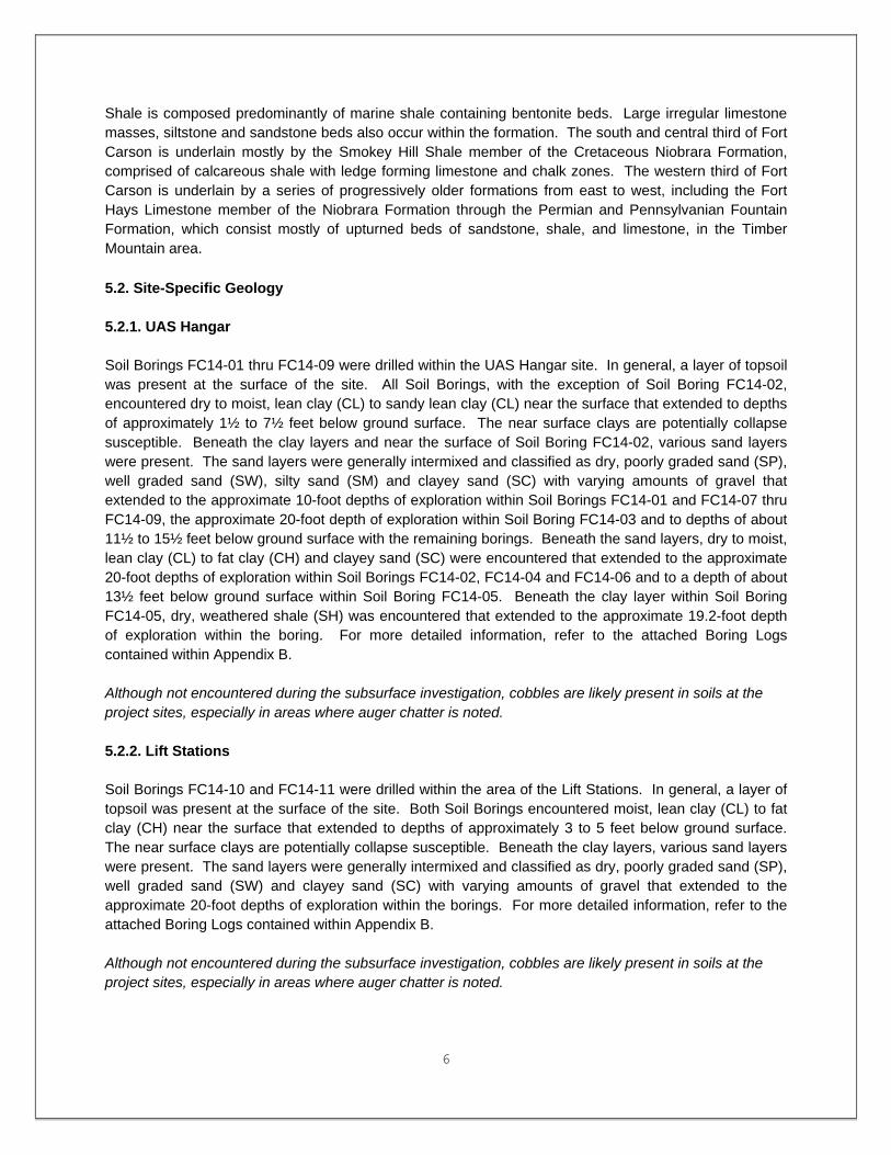
Shale is composed predominantly of marine shale containing bentonite beds. Large irregular limestone masses, siltstone and sandstone beds also occur within the formation. The south and central third of Fort Carson is underlain mostly by the Smokey Hill Shale member of the Cretaceous Niobrara Formation, comprised of calcareous shale with ledge forming limestone and chalk zones. The western third of Fort Carson is underlain by a series of progressively older formations from east to west, including the Fort Hays Limestone member of the Niobrara Formation through the Permian and Pennsylvanian Fountain Formation, which consist mostly of upturned beds of sandstone, shale, and limestone, in the Timber Mountain area. 5.2. Site-Specific Geology 5.2.1. UAS Hangar Soil Borings FC14-01 thru FC14-09 were drilled within the UAS Hangar site. In general, a layer of topsoil was present at the surface of the site. All Soil Borings, with the exception of Soil Boring FC14-02, encountered dry to moist, lean clay (CL) to sandy lean clay (CL) near the surface that extended to depths of approximately 1½ to 7½ feet below ground surface. The near surface clays are potentially collapse susceptible. Beneath the clay layers and near the surface of Soil Boring FC14-02, various sand layers were present. The sand layers were generally intermixed and classified as dry, poorly graded sand (SP), well graded sand (SW), silty sand (SM) and clayey sand (SC) with varying amounts of gravel that extended to the approximate 10-foot depths of exploration within Soil Borings FC14-01 and FC14-07 thru FC14-09, the approximate 20-foot depth of exploration within Soil Boring FC14-03 and to depths of about 11½ to 15½ feet below ground surface with the remaining borings. Beneath the sand layers, dry to moist, lean clay (CL) to fat clay (CH) and clayey sand (SC) were encountered that extended to the approximate 20-foot depths of exploration within Soil Borings FC14-02, FC14-04 and FC14-06 and to a depth of about 13½ feet below ground surface within Soil Boring FC14-05. Beneath the clay layer within Soil Boring FC14-05, dry, weathered shale (SH) was encountered that extended to the approximate 19.2-foot depth of exploration within the boring. For more detailed information, refer to the attached Boring Logs contained within Appendix B. Although not encountered during the subsurface investigation, cobbles are likely present in soils at the project sites, especially in areas where auger chatter is noted. 5.2.2. Lift Stations Soil Borings FC14-10 and FC14-11 were drilled within the area of the Lift Stations. In general, a layer of topsoil was present at the surface of the site. Both Soil Borings encountered moist, lean clay (CL) to fat clay (CH) near the surface that extended to depths of approximately 3 to 5 feet below ground surface. The near surface clays are potentially collapse susceptible. Beneath the clay layers, various sand layers were present. The sand layers were generally intermixed and classified as dry, poorly graded sand (SP), well graded sand (SW) and clayey sand (SC) with varying amounts of gravel that extended to the approximate 20-foot depths of exploration within the borings. For more detailed information, refer to the attached Boring Logs contained within Appendix B. Although not encountered during the subsurface investigation, cobbles are likely present in soils at the project sites, especially in areas where auger chatter is noted.

7
5.2.3. Fire Water Lagoon Soil Boring FC14-12 was drilled within the area of the Fire Water Lagoon. In general, a layer of topsoil was present at the surface of the site. The boring encountered moist, lean clay (CL) near the surface that extended to a depth of approximately 2½ feet below ground surface. The near surface clay is potentially collapse susceptible. Beneath the clay layer, various sand layers were present. The sand layers were generally intermixed and classified as dry, poorly graded sand (SP), well graded sand (SW) and silty sand (SM) with varying amounts of gravel that extended to the approximate 28-foot depth of exploration (depth of auger refusal) within the boring. For more detailed information, refer to the attached Boring Logs contained within Appendix B. Although not encountered during the subsurface investigation, cobbles are likely present in soils at the project sites, especially in areas where auger chatter is noted. 5.2.4. Relocated Parking Lot & Org Storage Building Soil Borings FC12-30 thru FC12-35 were previously drilled for the Aircraft Parts Storage Facility (GSAB Hangar) project and are located within the relocated parking lot & Org Storage Building site. All Soil Borings encountered dry, well graded sand with gravel (SW) at the surface that extended to depths of approximately 2½ to 3 feet below ground surface. Beneath the sand layer, all borings encountered dry to moist, lean clay (CL) to fat clay (CH) to clayey silt (ML/CL) that extended to depths of about 7½ to 8½ feet below ground surface within Soil Borings FC12-30 thru FC12-32 and to the approximate 10-foot depths of exploration within FC12-33 thru FC12-35. The near surface clays are potentially collapse susceptible. Beneath the lean clay, dry, well graded sand with gravel (SW) was encountered that extended to the approximate 10-foot depths of exploration within FC12-30 thru FC12-32. For more detailed information, refer to the attached Boring Logs contained within Appendix B.
Although not encountered during the subsurface investigation, cobbles are likely present in soils at the project sites, especially in areas where auger chatter is noted. 5.3. Groundwater Groundwater was not observed within any of the Soil Borings. Many Soil Borings experienced cave-in at depths ranging from about 3 to 17 feet below ground surface upon completion of drilling and removal of the augers. Groundwater information from Soil Borings may not be an accurate indicator of static ground water levels, which can vary considerably throughout the year. Groundwater is often encountered near the contact between overburden and weathered bedrock. Perched water lenses and saturated soil conditions near the surface are possible in response to short and long term precipitation trends. 5.4. Seismic Evaluation Reference the Structural Design Analysis, provided separately, for seismic coefficients used to design the project.

8
6. Subsurface Recommendations 6.1. General Soils encountered within the UAS Hangar, Lift Stations and Fire Water Lagoon generally consisted of potentially collapse susceptible lean clay (CL) to sandy lean clay (CL) to fat clay (CH) near the surface that extended to depths of approximately 1½ to 7½ feet below ground surface. Beneath the clay layers, various sand layers were present. The sand layers were generally intermixed and classified as dry, poorly graded sand (SP), well graded sand (SW), silty sand (SM) and clayey sand (SC) with varying amounts of gravel. In general, a layer of topsoil was present at the surface. For more detailed information, refer to the attached Boring Logs contained within Appendix B. Prior to the placement of structural fill, topsoil and surface vegetation must be stripped. Although stripping depths may vary across the site, a stripping depth of 6 inches is assumed. Within the UAS Hangar, the placement of approximately 20 feet of structural fill is anticipated to raise the grade of the site to design finished subgrade / grade elevations. Structural fill depths of up to 3 feet are anticipated in the area of the Lift Stations to obtain design finished subgrade / grade elevations. The Fire Water Lagoon requires excavation depths of up to approximately 18 feet below existing site grades to obtain design finished subgrade / grade elevations. Soils encountered within the relocated parking lot and Org Storage Building site consisted of dry, well graded sand with gravel (SW) at the surface that extended to depths of approximately 2½ to 3 feet below ground surface. Beneath the sand layer, all borings encountered dry to moist, lean clay (CL) to fat clay (CH) to clayey silt (ML/CL) that extended to depths of about 7½ to 10 feet below ground surface. The near surface clays are potentially collapse susceptible. For more detailed information, refer to the attached Boring Logs contained within Appendix B. Cuts and fills less than 1-foot in depth are anticipated in order to obtain design finished subgrade / grade elevations within the relocated parking lot and Org Storage Building site. Finished grades should have a slope of at least 1 percent and preferably 5 percent maintained within 10 feet of structures to ensure adequate drainage away from the structures. 6.2. Foundation Recommendations 6.2.1 UAS Hangar The hangar will be placed on approximately 20 feet of structural fill. In order to reduce the amount of total and differential settlements induced by this fill placement, fills must be in place at least 30 days prior to the start of building construction. A 60 day period is recommended if fills are comprised predominantly of cohesive material. See Section 7. Construction Considerations for recommendations regarding suitable material and placement for structural fill.

9
Wall and isolated (column) footings bearing on non-expansive structural fill may be designed using a maximum allowable bearing pressure of 2,500 psf. Floor Slabs. A coefficient of subgrade reaction (k value) of 150 pci may be used for design for non-expansive structural fills placed as described in Section 7. Any slab that will be traversed by aircraft is to be considered airfield pavement and be designed and specified as such. Floor slabs in areas that do not include moisture-sensitive floor covering and do not require a water-proof membrane for other purposes such as liquid spill containment, may have the vapor barrier membrane omitted. A capillary water break should be retained. A vapor barrier membrane is to be included between the capillary break and floor slab for floor slabs located in areas that do include moisture-sensitive floor covering. Pavement Design. Pavement will include paved parking, hangar access / maintenance apron, runway extension and overrun with overlay, and taxiways. Pavements will be placed on approximately 20 feet of structural fill. In order to reduce the amount of total and differential settlements induced by this fill placement, fills must be in place at least 30 days prior to the start of pavement construction. A 60 day period is recommended if fills are comprised predominantly of cohesive material. Within the depth below pavement where the paving specification governs the work, the requirements in the earthwork spec for pavement subgrade are to be followed. Light pavements for parking and service driveways may use a coefficient of subgrade reaction (k value) of 150 pci and a CBR of 8 for subgrade compacted to 95% of the materials maximum Modified Proctor density. Soil Properties. In situ soil descriptions can be found on the attached Boring Logs contained within Appendix B. In most areas, the structures will be placed on structural fill to obtain design finished subgrade / grade elevations. A compacted fill density of 120 pcf, a coefficient of friction between formed concrete and soil of 0.35 and the lateral earth pressure values in Section 6.6 are suitable for this site. 6.2.2. Lift Stations The base of the Sanitary Lift Station is located about 18.5 feet below finished ground surface, while the base of the Industrial Lift Station is located about 17 feet below finished ground surface. Structural fill depths of up to 3 feet are anticipated in these areas to obtain design finished subgrade / grade elevations. No delay between fill placement and construction is required. Based on Soil Borings FC14-10 and FC14-11, which are located within the areas of the Lift Stations, and the anticipated base depths of the Lift Stations, the foundations will bear within the medium dense to very dense, poorly graded sand (SP), well graded sand (SW) or clayey sand (SC) with varying amounts of gravel. Foundations bearing within the identified sand layers may be designed using a maximum allowable bearing pressure of 2,500 psf. Soil Properties. In situ soil descriptions can be found on the attached Boring Logs contained within Appendix B. An in-situ density of 120 pcf, a coefficient of friction between formed concrete and soil of 0.35 and the lateral earth pressure values in Section 6.6 are suitable for this site.

10
6.2.3 Org Storage Building Soils encountered within the relocated parking lot and Org Storage Building site consisted of dry, well graded sand with gravel (SW) at the surface that extended to depths of approximately 2½ to 3 feet below ground surface. Beneath the sand layer, all borings encountered dry to moist, lean clay (CL) to fat clay (CH) to clayey silt (ML/CL) that extended to depths of about 7½ to 10 feet below ground surface. The near surface clays are potentially collapse susceptible. Cuts and fills less than 1-foot in depth are anticipated in order to obtain design finished subgrade / grade elevations within the Org Storage Building site. Due to the presence of potentially collapse susceptible clays near the building foundation bearing elevation, overexcavation and replacement of the foundation bearing soils is required beneath each footing. The overexcavation shall extend 2 feet below and 1-foot beyond each foundation perimeter. See Section 7. Construction Considerations for recommendations regarding suitable material for placement for structural fill. Wall and isolated (column) footings bearing on non-expansive structural fill may be designed using a maximum allowable bearing pressure of 2,500 psf. Floor Slabs. Cuts and fills less than 1-foot in depth are anticipated in order to obtain design finished subgrade / grade elevations within the Org Storage Building site. A coefficient of subgrade reaction (k value) of 150 pci may be used for design for floor slabs placed on structural fill bearing on the near surface well graded sand with gravel (GW) encountered at the surface of the site or for subgrade compacted to 95% of the materials maximum Modified Proctor density. Floor slabs in areas that do not include moisture-sensitive floor covering and do not require a water-proof membrane for other purposes such as liquid spill containment, may have the vapor barrier membrane omitted. A capillary water break should be retained. A vapor barrier membrane is to be included between the capillary break and floor slab for floor slabs located in areas that do include moisture-sensitive floor covering. Pavement Design. Cuts and fills less than 1-foot in depth are anticipated in order to obtain design finished subgrade / grade elevations within the relocated parking lot. Light pavements for parking and service driveways may use a coefficient of subgrade reaction (k value) of 150 pci and a CBR of 8 for pavements placed on structural fill bearing on the near surface well graded sand with gravel (GW) encountered at the surface of the site or for subgrade compacted to 95% of the materials maximum Modified Proctor density. Soil Properties. In situ soil descriptions can be found on the attached Boring Logs contained within Appendix B. In most areas, the structures will be placed on structural fill to obtain design finished subgrade / grade elevations. A compacted fill density of 120 pcf, a coefficient of friction between formed concrete and soil of 0.35 and the lateral earth pressure values in Section 6.6 are suitable for this site.

11
6.3. Settlement Potential Total settlement of conventional footings bearing on soils identified above is not anticipated to exceed 1-inch, with differential settlement not to exceed 0.5 inches. If the surcharge period for deep fills is not performed, damaging settlement and differential settlement is likely to occur. 6.4. Cementing Properties Sulfate-resistant cement is not required for concrete in contact with soils on this project. Due to the potential for alkali-aggregate reactivity within the boundaries of the Omaha District, cement meeting the optional chemical requirements for low alkali cement within Table 2 of ASTM C 150 should be specified for all concrete. The Resource Conservation Recovery Act (RCRA) mandates, where possible, all concrete specifications should include the option to use pozzolan as a partial replacement for Portland cement. 6.5. Corrosion Potential Soil resistivity tests were not performed on representative samples from project Soils Borings since a majority of the structures will be supported on 20 feet of structural fill. 6.6. Lateral Earth Pressures Cohesive, on-site, soil backfill or similar imported materials may be assumed to have an at-rest pressure coefficient of 0.7, an active coefficient of 0.50 and a passive coefficient of 2.0; consistent with an angle of internal friction of 20 degrees. On-site, granular soil or similar imported materials may be assumed to have coefficients of 0.45, 0.28 and 3.5, respectively; consistent with an angle of internal friction of 34 degrees. A compacted density of 120 pcf is appropriate. 7. Construction Considerations 7.1 Description and Placement of Fill Within the UAS Hangar site, the building and pavements will be placed on approximately 20 feet of structural fill. In order to reduce the amount of total and differential settlements induced by this fill placement, fills must be in place at least 30 days prior to the start of building and pavement construction. A 60 day period is recommended if fills are comprised predominantly of cohesive material. Because of the large volume of fill required, the definition of suitable material can be fairly broad. Additionally, the definition may be different for material placed greater than 5 feet below the base of footings and pavement as compared to within that zone. In general terms, a non-expansive cohesive material or a granular material with enough fines to bind the aggregate together and reduce permeability is needed. For fill located greater than 5 feet below the base of building footings and pavements and below where the paving specification governs the work, the structural fill material may consist of soil meeting one of the following criteria:

12
- Soil with a maximum 4-inch stone size, approximately 90 percent passing the No. 4 sieve, and
between 10 and 80 percent passing the No. 200 sieve. The maximum Liquid Limit in accordance with ASTM D 4318 should be 41 and the maximum Plasticity Index 25.
- Colorado DOT Class 6 aggregate. Much of the on-site soils are suitable for this purpose; however, near-surface soil identified as potentially collapse susceptible would have to be processed, pulverized and moisture-conditioned prior to use to remove that susceptibility. For fill located within 5 feet of the base of footings and pavements, the restrictions on maximum stone size and soil plasticity are greater. Examples of suitable, non-expansive, structural fill for this zone are listed below:
- Soil with a maximum 2-inch stone size, approximately 90 percent passing the No. 4 sieve, and between 10 and 80 percent passing the No. 200 sieve if the fines have low plasticity. The maximum Liquid Limit in accordance with ASTM D 4318 is 21 and the maximum plasticity index 12.
- Colorado DOT Class 6 aggregate. - Other materials with similar gradations and plasticity characteristics. If alternative materials are
used, the maximum swelling upon inundation under a 500 psf confining load should be not more than two-percent.
Engineered fill should be placed in maximum 8-inch loose thickness lifts and compacted to not less than 95% of materials maximum Modified Proctor density at a moisture content of -2 to +2 percent of optimum moisture.

APPENDIX A BORING LOCATION PLANS

XX
XX
XX
XX
XX
XX
XX
XX
XX
XX
XX
XX
xx
xx
5695
5695
5700
5700
5700
CP TEST
W
CP TEST
5705
5705
5705
5705
5705
5705
5705
5710
5710
5710
5710
5710
5710
5710
5710
APPROXIMATE LOCATION OF WATERLINE PLOTTED
BASED ON EXISTING MANHOLES, VALVES, &
MAKER POSTS AND G-TAB MAPPING.
5715
5715
5715
5715
5715
5715
5715
5720
5720
5720
5720
5720 5
720
5720
5720
5725
5725
5725
5725
5725
5725
5725
5725
5725
5725
5730
5730
5730
5730
5730
5730
5730
5730
5730
5730
5730
5730
5735
5735
5735
5735
5735
5735
5735
5735
5735
5735
5735
5735
5735
5740
57405740
5740
5740
5740
5740
5740
5740
5740
5740
5740
5740
5740
5740
5745
5745
5745
5745
5745
5745
5745
5745
5745
5745
5745
5745
5745
5750
5750
5750
5750
5750
5750
5750
5750
5750
5750
5750
5750
5750
5750
5755
5755
5755
5755
5755
5755
5755
5755
5755
5755
5755
5755
5755
FC-11-62
5760
5760
5760
5760
5760
5760
5760
5760
5760
5760
5760
5760
5760
5760
5760
8'
CH
AIN LI
NK
15"
CMP
INV. = 5765.22
INV. = 5764.61
FC-11-61
5765
5765
5765
5765
5765
5765
5765
5765
5765
5765
5765
5765
5765
5765
5765
5765
5765
5765
GATE
8'
CH
AIN LI
NK
8'
CH
AIN LIN
K
FC-11-60
8'
CH
AIN LI
NK
FC-11-70
5770
5770
5770
5770
5770
5770
5770
5770
5770
5770
5770
5770
5770
5770
5770
5770
5770
5770
5770
5770
5770
5770
8.5' CHAIN
LINK
VERTICAL 12" PVC
IN CONCRETE
8'
CH
AIN LIN
K
FC-11-57
FC-11-58
FC-11-59
5775
5775
5775
5775
5775
5775
5775
5775
5775
5775
5775
5775
5775
5775
5775
5775
5775
FC-11-54
FC-11-55
FC-11-56
FC-11-54
8'
CH
AIN LIN
K
8'
CH
AIN LIN
K
FC-11-53
FC-11-71
5780
5780
5780
5780
5780
5780
5780
5780
5780
5780
5780
5780
5780
5780
5780
5780
5780
5780
5780
5780
5780
5780
FC-11-53
5780
H
8.5'
CH
AIN LIN
K
12"
PVC
12"
PVC
FC-11-112
FC-11-113
5785
5785
5785
5785
5785
5785
5785
5785
5785
5785
5785
5785
5785
5785
5785
5785
CO
H
SANITARY MH (ABANDONED)
RIM = 5788.86
INV. OUT SE = 5785.20
INV. IN NW = 5785.21S
XJ
XJ
SANITARY MH (ABANDONED)
RIM = 5791.65
INV. OUT SE = 5786.99
INV. IN NW = 5787.00
12"
PVC
FC-11-52
FC-11-73
5790
5790
5790
5790
5790
5790
5790
5790
5790
5790
5790
5790
5790
5790
5790
5790
5790
5790
S
FC-11-52
CONCRETE
CENTERLINE RUNWAY
N: 1306969.68
E: 3213797.00
ELEV. = 5795.85
P.K. NAIL IN
FC-11-51
GR
AVEL
5795
5795
5795
5795
5795
5795
5795
5795
5795
5795
5795
XJ
FC-11-51
5795
MONITORING WELL
w/3 PROTECTIVE
BOLLARDS
SANITARY MH (ABANDONED)
RIM = 5798.77
INV. OUT SE = 5794.69
INV. IN NW = 5794.72
FC-11-50
GRAVEL
5800
5800
5800
5800
5800
5800
MW
S
MONITORING WELL
w/3 PROTECTIVE
BOLLARDS
MONITORING WELL
w/3 PROTECTIVE
BOLLARDS
5805
5770
5770
5770
5775
5775
5775
5775
5775
5775
5780
5780
5780
5781
5779
57785780
5780
5780
5784
5783
5782
5785
5785
5785
5785
5785
5785
5787
5786
5790
5790
5790
5791
5790
5789
5788
5791
5790
5790
5794
5793
5792
5792
5795
5795
5795
5795
5795
5795
5795
5797
5796
5798
5798
5797
5797
SO
LICIT
ATIO
N N
O.:
FIL
E N
AM
E:
DW
N B
Y:
CK
D B
Y:
DE
SIG
NE
D B
Y:
DE
SC
RIP
TIO
N
1
D
2 3
C
4 5
A
B
MA
RK
AP
PR.
DA
TE:
FIL
E N
UM
BE
R:
SIZ
E:
SU
BMIT
TE
D B
Y:
PL
OT S
CA
LE:
PL
OT D
AT
E:
DA
TE
MA
RK
DE
SC
RIP
TIO
N
CO
NT
RA
CT N
O.:
IDENTIFICATION
SHEET
DA
TE
AP
PR.
®of Engineers
US Army Corps
of Engineers
US Army Corps
XX
XX
XX
XX
XX
XX
XX
XX
XX
XX X
X
XX
XX
XX
XX
XX
XX
1+00
2+00
3+00
4+00
5+00
6+00
7+00
8+00
9+00
STA 0+
00.00 PO
B
STA 6+
67.36PI
STA 7+
20.00PI
STA 7+
65.00 PC
STA 8+04.27
PT
STA 8+79.08
PC
STA 9+
18.35 PT
STA 9+
21.33 POE
ST
A 7
+90.0
0 PI
ST
A 9
+04.0
8PI
N 1,306,522.63
E 3,212,678.80 N 1,306,454.54
E 3,213,040.76
N 1,306,342.91
E 3,212,922.22
N 1,306,288.56
E 3,213,197.08
N 1,306,157.99
E 3,213,096.36
N 1,306,020.73
E 3,213,253.78
N 1,305,797.96
E 3,213,463.57
N 1,305,575.19
E 3,213,673.35
N 1,305,410.86
E 3,213,898.86
N 1,305,377.38
E 3,213,778.71
N 1,305,239.17
E 3,213,962.81
FC14-01
FC14-02
FC14-03
FC14-04
FC14-05
FC14-06
FC14-07
FC14-08
FC14-09
FC14-10
FC14-11
FC14-12
N 1,306,313.89
E 3,213,063.41
U.S.
AR
MY C
OR
PS O
F E
NGIN
EE
RS
OM
AH
A,
NE
BR
AS
KA
OM
AH
A DIS
TRIC
T
OMAHA DISTRICT
N
DP
H
DP
H
03/0
1/2
014
DP
H
BO
RIN
G L
OC
ATIO
N P
LA
NF211-1
0-0
8
CO
LO
RA
DO
FC
W9
B-1
01.d
gn
4T
H I
D C
AB, U
AS H
AN
GA
R
PN
81357 (F
Y15)
FO
RT C
AR
SO
N
B-101
SCALE 1" = 100'
200'100'0

HEADWALL
HEADWALL
INV. = 5838.22
INV. = 5836.36
24"
CM
P
36"
CM
P
24" CMP
24"
CMP
24"
CM
P
24"
CM
P
24"
CM
P
APPROXIMATE LOCATION OF 6" PVC FORCE MAIN
PLOTTED BASED ON EXISTING PUMP STATION AND
SANITARY MANHOLES & G-TAB MAPPING. LOCATION
COULD NOT BE FIELD VERIFIED.
5835
5835
5840
5840
5840
CB
CB
CB
CBCB
CB
CB
CB
X
X
X
CB
CB
CB
CBCB
CBCB
CB
CB
BOLLARDS
BOLLARDS
BOLLARDS
BOLLARDS
BOLLARDS
BOLLARDS
BOLLARDS
BOLLARDS
BOLLARD
GATE
BOLLARDS
MAINTE
NANCE PIT
AREA INLET (2 GRATES)
TOP INLET = 5847.86
INV. IN WEST = 5841.54
INV. IN NW = 5841.06
INV. OUT SE = 5840.96
STORM (CURB INLET)
TOP INLET = 5845.38
INV. IN NW = 5839.38
24" CMPAREA INLET
TOP INLET = 5851.75
INV. OUT EAST = 5846.95
INV. IN NE = 5839.38
INV. OUT SE = 5838.88
STORM (CURB INLET)
TOP INLET = 5846.72
INV. OUT SW = 5841.17
AREA INLET (2 GRATES)
TOP INLET = 5846.81
INV. OUT SE = 5842.06
FUEL OVERFLOW
CATCH BASIN
TOP GRATE = 5850.54
(NO OUTLET)
24"
CMP
AREA INLET
TOP INLET = 5848.64
INV. OUT SW = 5844.72
AREA INLET (2 GRATES)
TOP INLET = 5848.94
INV. IN NE = 5843.44
INV. OUT SW = 5843.04
24"
CM
P
24"
CMP
AREA INLET (2 GRATES)
TOP INLET = 5847.73
INV. IN NE = 5841.73
INV. IN NW = 5841.23
INV. OUT SE = 5841.13
AREA INLET (2 GRATES)
TOP INLET = 5852.44
INV. IN NE = 5847.34
INV. OUT SE = 5847.22
AREA INLET
TOP INLET = 5852.87
INV. OUT SW = 5848.97
AREA INLET (2 GRATES)
TOP INLET = 5843.84
INV. IN NW = 5839.64
INV. OUT SW = 5839.54
AREA INLET (2 GRATES)
TOP INLET = 5845.51
INV. OUT SE = 5840.76
AREA INLET (2 GRATES)
TOP INLET = 5844.49
INV. OUT SE = 5839.62
INV. IN NW = 5839.58
8' C
HAIN LIN
K
8'
CH
AIN
LIN
K
8' C
HAIN LIN
K
8' C
HAIN LIN
K
8'
CH
AIN
LIN
K
8'
CH
AIN
LIN
K
8'
CH
AIN
LIN
K
8' C
HAIN LIN
K
8' C
HAIN LIN
K
8'
CH
AIN
LIN
K
8' C
HAIN LIN
K
CONCRETE
CONCRETE
CONCRETE
APPROXIMATE LOCATION OF WATERLINE
PLOTTED BASED ON G-TAB MAPPING.
APPROXIMATE LOCATION OF WATERLINE
PLOTTED BASED ON G-TAB MAPPING.
GRAVEL
GRAVEL
GRAVEL
GRAVEL
GRAVEL
5850
5850
5850
5850
5855
5855
5845
5845
5845
5845
D
W
P
POV's
8'
CH
AIN
LIN
K
XX
XX
XX
XX
XX
XX
XX
XX
XX
XX
XX
FC12-30
FC12-31
FC12-33
FC12-34
FC12-32
FC12-35
ORG. STORAGE BLDG
CONCRETE PAVING
HEAVY DUTY
N 1,308,230.65
E 3,209,042.60
N 1,308,041.63
E 3,208,863.50
N 1,307,912.59
E 3,209,195.28
N 1,307,775.80
E 3,209,018.41
N 1,307,716.72
E 3,208,808.10
N 1,308,094.50
E 3,208,632.34

APPENDIX B BORING LOGS

Gus Pech 1300C
18. SIGNATURE AND TITLE OF INSPECTOR
13. TOTAL NUMBER CORE BOXES
VERTICAL
Hand-held GPSN 38° 40' 21.6"W 104° 45' 16.3"+-25'
Note: Although not encountered during the site investigation, cobbles are likely present in soils at the project site(especially in areas where auger chatter is noted).
10 ft
0 ft
10 ft
5785.5
STARTED
9. COORDINATE SYSTEM1. PROJECT
16. ELEVATION TOP OF BORING
USACE, Omaha District
INSTALLATION
FC14-01
4/11/14
11. MANUFACTURER'S DESIGNATION OF DRILL
5. DIRECTION OF BORING
4
HORIZONTAL
14. ELEVATION GROUND WATER
2NWO
UNDISTURBED
17. TOTAL CORE RECOVERY FOR BORING
State Plane
---
4 1/4" ID HSALOCATION COORDINATES
1OF
DEG FROMVERTICAL
DIVISION
2. HOLE NUMBER
INCLINED
10. SIZE AND TYPE OF BIT
DISTURBED
VERTICAL
SHEETSButts Army Airfield
3. DRILLING AGENCY
COMPLETED
0
15. DATE BORING
Kirk Thomas
William J. Merritt Geologist
1306522.630N 3212678.800E
4. NAME OF DRILLER
N/A
SHEET
12. TOTAL SAMPLES
LAB TESTING LOG
UAS Hangar FY15
BEARING
4/11/14
6. THICKNESS OF OVERBURDEN
7. DEPTH DRILLED INTO ROCK
8. TOTAL DEPTH OF BORING
Project Datum
Static Water Level Depth Groundwater Encountered
LOCATION SKETCH/COMMENTS SCALE:
FC14-01PROJECT
UAS Hangar FY15 Ft. Carson, COHOLE NO
NWO FORM 1836-A SHEET 1 of 2
Boring Designation FC14-01
DEC 10Boring Designation FC14-01
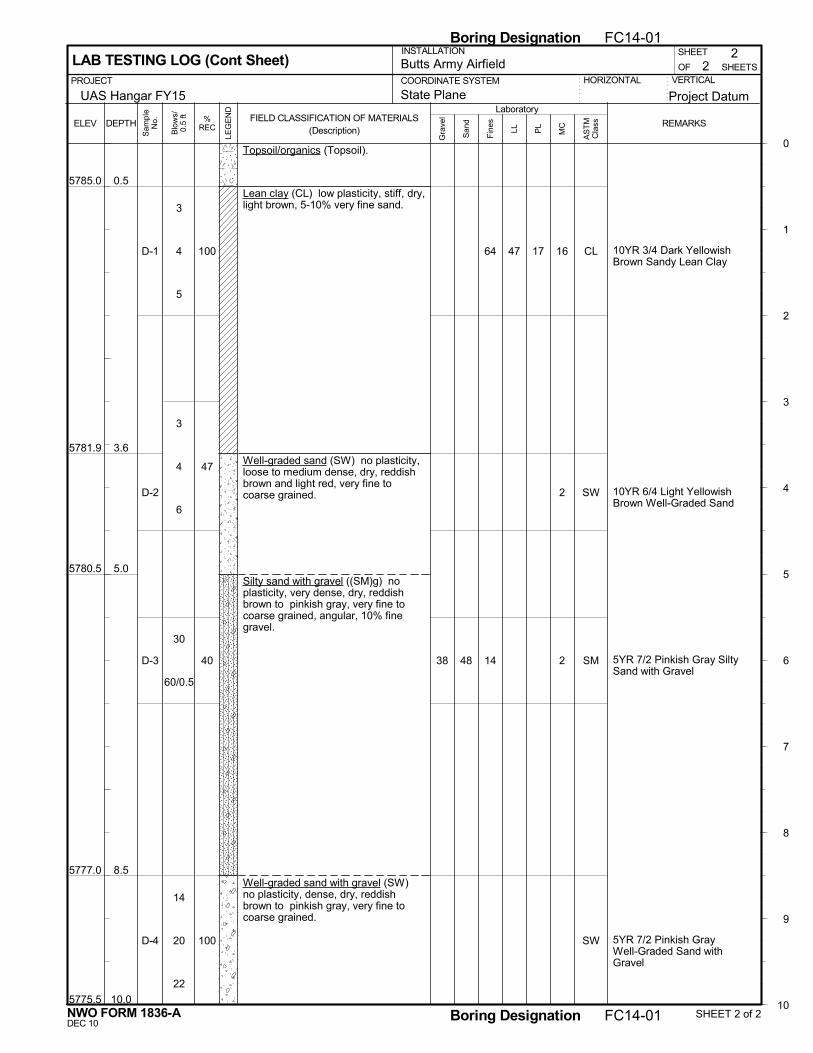
1747
0.5
3.6
5.0
8.5
10.0
Topsoil/organics (Topsoil).
Lean clay (CL) low plasticity, stiff, dry,light brown, 5-10% very fine sand.
Well-graded sand (SW) no plasticity,loose to medium dense, dry, reddishbrown and light red, very fine tocoarse grained.
Silty sand with gravel ((SM)g) noplasticity, very dense, dry, reddishbrown to pinkish gray, very fine tocoarse grained, angular, 10% finegravel.
Well-graded sand with gravel (SW)no plasticity, dense, dry, reddishbrown to pinkish gray, very fine tocoarse grained.
10YR 3/4 Dark YellowishBrown Sandy Lean Clay
10YR 6/4 Light YellowishBrown Well-Graded Sand
5YR 7/2 Pinkish Gray SiltySand with Gravel
5YR 7/2 Pinkish GrayWell-Graded Sand withGravel
48
64
14
5785.0
5781.9
5780.5
5777.0
5775.5
38
16
2
2
CL
SW
SM
SW
VERTICALOF
PL
2
COORDINATE SYSTEM
Project Datum
2 SHEETS
PROJECT
Laboratory
SHEET
LL
0
1
2
3
4
5
6
7
8
9
10
DEPTHFIELD CLASSIFICATION OF MATERIALS
(Description)REMARKS
San
d
Fin
esELEV
LAB TESTING LOG (Cont Sheet)INSTALLATION
Butts Army Airfield
State PlaneUAS Hangar FY15HORIZONTAL
Gra
vel
MC
Sam
ple
No.
LEG
EN
D
%REC
Blo
ws/
0.5
ft
AS
TM
Cla
ss
NWO FORM 1836-A SHEET 2 of 2
Boring Designation FC14-01
DEC 10Boring Designation FC14-01
D-1
D-2
D-3
D-4
100
47
40
100
3
4
5
3
4
6
30
60/0.5
14
20
22

Gus Pech 1300C
18. SIGNATURE AND TITLE OF INSPECTOR
13. TOTAL NUMBER CORE BOXES
VERTICAL
Hand-held GPSN 38° 40' 20.7"W 104° 45' 13.0"+- 25'
Collapse depth 6.55'
Note: Although not encountered during the site investigation, cobbles are likely present in soils at the project site(especially in areas where auger chatter is noted).
20 ft
0 ft
20 ft
5783.0
STARTED
9. COORDINATE SYSTEM1. PROJECT
16. ELEVATION TOP OF BORING
USACE, Omaha District
INSTALLATION
FC14-02
4/10/14
11. MANUFACTURER'S DESIGNATION OF DRILL
5. DIRECTION OF BORING
7
HORIZONTAL
14. ELEVATION GROUND WATER
3NWO
UNDISTURBED
17. TOTAL CORE RECOVERY FOR BORING
State Plane
---
4 1/4" ID HSALOCATION COORDINATES
1OF
DEG FROMVERTICAL
DIVISION
2. HOLE NUMBER
INCLINED
10. SIZE AND TYPE OF BIT
DISTURBED
VERTICAL
SHEETSButts Army Airfield
3. DRILLING AGENCY
COMPLETED
0
15. DATE BORING
Kirk Thomas
William J. Merritt Geologist
1306454.540N 3213040.760E
4. NAME OF DRILLER
N/A
SHEET
12. TOTAL SAMPLES
LAB TESTING LOG
UAS Hangar FY15
BEARING
4/10/14
6. THICKNESS OF OVERBURDEN
7. DEPTH DRILLED INTO ROCK
8. TOTAL DEPTH OF BORING
Project Datum
Static Water Level Depth Groundwater Encountered
LOCATION SKETCH/COMMENTS SCALE:
FC14-02PROJECT
UAS Hangar FY15 Ft. Carson, COHOLE NO
NWO FORM 1836-A SHEET 1 of 3
Boring Designation FC14-02
DEC 10Boring Designation FC14-02

0.5
3.0
5.0
Topsoil/organics (Topsoil) clayey.
Well-graded sand (SW) no plasticity,dense, dry, reddish brown, very fine tocoarse grained, 10% fine gravel.
Well-graded sand with gravel ((SW)g)no plasticity, dense, dry, reddishbrown, very fine to coarse grained,20% fine gravel.
Well-graded sand (SW) no plasticity,dense, dry, reddish brown, very fine tocoarse grained.
@ 8 ft, very dense.
5YR 7/2 Pinkish GrayWell-Graded Sand withGravel
5YR 6/3 Light Reddish BrownWell-Graded Sand withGravel
5YR 6/3 Light Reddish BrownWell-Graded Sand with Silt
5YR 5/3 Reddish BrownWell-Graded Sand
82 8
5782.5
5780.0
5778.0
10
1
1
1
SW
SW
SW-SM
SW
VERTICALOF
PL
2
COORDINATE SYSTEM
Project Datum
3 SHEETS
PROJECT
Laboratory
SHEET
LL
0
1
2
3
4
5
6
7
8
9
10
DEPTHFIELD CLASSIFICATION OF MATERIALS
(Description)REMARKS
San
d
Fin
esELEV
LAB TESTING LOG (Cont Sheet)INSTALLATION
Butts Army Airfield
State PlaneUAS Hangar FY15HORIZONTAL
Gra
vel
MC
Sam
ple
No.
LEG
EN
D
%REC
Blo
ws/
0.5
ft
AS
TM
Cla
ss
NWO FORM 1836-A SHEET 2 of 3
Boring Designation FC14-02
DEC 10Boring Designation FC14-02
D-1
D-2
D-3
D-4
100
73
100
9
22
24
10
24
23
11
16
19
17
27
31

12.5
15.5
20.0
Well-graded sand (SW) no plasticity,very dense, dry, reddish brown, veryfine to coarse grained, (con't.).
@ 10.5 ft, dense.
Well-graded sand with gravel (SW)dense, dry, reddish brown, very fine tocoarse grained, 20% fine to coarsegravel.
Lean to fat clay with sand ((CL/CH)s)medium plasticity, stiff, damp, olivegray.
5 YR 6/4 Light ReddishBrown Well-Graded Sand
2.5 YR 6/3 Light ReddishBrown Well-Graded Sandwith Gravel
2.5Y 7/1 Light Gray Lean toFat Clay with Sand
85
5770.5
5767.5
5763.0
SW
SW
CL-CH
CL-CH
VERTICALOF
PL
3
COORDINATE SYSTEM
Project Datum
3 SHEETS
PROJECT
Laboratory
SHEET
LL
10
11
12
13
14
15
16
17
18
19
20
DEPTHFIELD CLASSIFICATION OF MATERIALS
(Description)REMARKS
San
d
Fin
esELEV
LAB TESTING LOG (Cont Sheet)INSTALLATION
Butts Army Airfield
State PlaneUAS Hangar FY15HORIZONTAL
Gra
vel
MC
Sam
ple
No.
LEG
EN
D
%REC
Blo
ws/
0.5
ft
AS
TM
Cla
ss
NWO FORM 1836-A SHEET 3 of 3
Boring Designation FC14-02
DEC 10Boring Designation FC14-02
D-5
D-6
D-7
100
80
93
41
21
20
12
19
15
4
3
8

Gus Pech 1300C
18. SIGNATURE AND TITLE OF INSPECTOR
13. TOTAL NUMBER CORE BOXES
VERTICAL
Hand-held GPSN 38° 40' 19.8"W 104° 45' 13.9"+-35'
Offset 10' south due to slope.
Collapse depth 10'
Note: Although not encountered during the site investigation, cobbles are likely present in soils at the project site(especially in areas where auger chatter is noted).
20 ft
0 ft
20 ft
5778.0
STARTED
9. COORDINATE SYSTEM1. PROJECT
16. ELEVATION TOP OF BORING
USACE, Omaha District
INSTALLATION
FC14-03
4/10/14
11. MANUFACTURER'S DESIGNATION OF DRILL
5. DIRECTION OF BORING
7
HORIZONTAL
14. ELEVATION GROUND WATER
3NWO
UNDISTURBED
17. TOTAL CORE RECOVERY FOR BORING
State Plane
---
4 1/4" ID HSALOCATION COORDINATES
1OF
DEG FROMVERTICAL
DIVISION
2. HOLE NUMBER
INCLINED
10. SIZE AND TYPE OF BIT
DISTURBED
VERTICAL
SHEETSButts Army Airfield
3. DRILLING AGENCY
COMPLETED
0
15. DATE BORING
Kirk Thomas
William J. Merritt Geologist
1306342.910N 3212922.220E
4. NAME OF DRILLER
N/A
SHEET
12. TOTAL SAMPLES
LAB TESTING LOG
UAS Hangar FY15
BEARING
4/10/14
6. THICKNESS OF OVERBURDEN
7. DEPTH DRILLED INTO ROCK
8. TOTAL DEPTH OF BORING
Project Datum
Static Water Level Depth Groundwater Encountered
LOCATION SKETCH/COMMENTS SCALE:
FC14-03PROJECT
UAS Hangar FY15 Ft. Carson, COHOLE NO
NWO FORM 1836-A SHEET 1 of 3
Boring Designation FC14-03
DEC 10Boring Designation FC14-03

1535
0.5
2.5
8.0
Fill (COBBLES) cobbles and smallboulders on surface.
Sandy lean clay (s(CL)) low plasticity,medium stiff, damp, light brown.
Poorly graded sand with gravel((SP)g) loose, dry, light brown, veryfine grained, with fine gravel.
@ 5.5 ft, very dense, dry.
Well-graded sand with gravel ((SW)g)no plasticity, medium dense, dry,brown to black, very fine to coarsegrained, 20% fine gravel.
7.5 YR 4/3 Brown Lean Claywith Sand
5 YR 5/3 Reddish BrownPoorly Graded Sand withGravel
Light Auger Chatter
5 YR 7/3 Pink Poorly GradedSand6-6.5 foot drive stoppedadvancing at 6 blows.
6-7 feet bgs, Heavy AugerChatter
5 YR 6/4 Light ReddishBrown Well-Graded Sandwith Gravel
71
5777.5
5775.5
5770.0
19
5
3
CL
SP
SP
SW
VERTICALOF
PL
2
COORDINATE SYSTEM
Project Datum
3 SHEETS
PROJECT
Laboratory
SHEET
LL
0
1
2
3
4
5
6
7
8
9
10
DEPTHFIELD CLASSIFICATION OF MATERIALS
(Description)REMARKS
San
d
Fin
esELEV
LAB TESTING LOG (Cont Sheet)INSTALLATION
Butts Army Airfield
State PlaneUAS Hangar FY15HORIZONTAL
Gra
vel
MC
Sam
ple
No.
LEG
EN
D
%REC
Blo
ws/
0.5
ft
AS
TM
Cla
ss
NWO FORM 1836-A SHEET 2 of 3
Boring Designation FC14-03
DEC 10Boring Designation FC14-03
D-1
D-2
D-3
D-4
100
27
38
100
2
3
3
3
4
4
16
60/0.3
7
13
14

10.5
13.0
18.5
20.0
Well-graded sand with gravel ((SW)g)no plasticity, medium dense, dry,brown to black, very fine to coarsegrained, 20% fine gravel, (con't.).Well-graded sand (SW) mediumdense, damp, reddish brown andwhite, very fine to coarse grained,trace clay, trace fine gravel.
Well graded sand with clay (SW-SC)no plasticity, medium dense, dry,reddish brown and white, very fine tocoarse grained, increasing clay, tracefine gravel.
Poorly graded sand with clay (SP-SC)no plasticity, dense, dry, reddishbrown, no gravel.
5 YR 6/4 Light ReddishBrown Well-Graded Sand
5 YR 6/4 Light ReddishBrown Well-Graded Sandwith Clay
7.5 YR 5/4 Brown PoorlyGraded Sand with Clay
5767.5
5765.0
5759.5
5758.0
SW
SW-SC
SP-SC
VERTICALOF
PL
3
COORDINATE SYSTEM
Project Datum
3 SHEETS
PROJECT
Laboratory
SHEET
LL
10
11
12
13
14
15
16
17
18
19
20
DEPTHFIELD CLASSIFICATION OF MATERIALS
(Description)REMARKS
San
d
Fin
esELEV
LAB TESTING LOG (Cont Sheet)INSTALLATION
Butts Army Airfield
State PlaneUAS Hangar FY15HORIZONTAL
Gra
vel
MC
Sam
ple
No.
LEG
EN
D
%REC
Blo
ws/
0.5
ft
AS
TM
Cla
ss
NWO FORM 1836-A SHEET 3 of 3
Boring Designation FC14-03
DEC 10Boring Designation FC14-03
D-5
D-6
D-7
73
100
100
17
19
12
7
13
14
7
13
30

Gus Pech 1300C
18. SIGNATURE AND TITLE OF INSPECTOR
13. TOTAL NUMBER CORE BOXES
VERTICAL
Hand-held GPSN 38° 40' 19.1"W 104° 45' 13.5"+-40'
Collapse depth 7.43'
Note: Although not encountered during the site investigation, cobbles are likely present in soils at the project site(especially in areas where auger chatter is noted).
20 ft
0 ft
20 ft
5777.0
STARTED
9. COORDINATE SYSTEM1. PROJECT
16. ELEVATION TOP OF BORING
USACE, Omaha District
INSTALLATION
FC14-04
4/10/14
11. MANUFACTURER'S DESIGNATION OF DRILL
5. DIRECTION OF BORING
7
HORIZONTAL
14. ELEVATION GROUND WATER
3NWO
UNDISTURBED
17. TOTAL CORE RECOVERY FOR BORING
State Plane
---
4 1/4" ID HSALOCATION COORDINATES
1OF
DEG FROMVERTICAL
DIVISION
2. HOLE NUMBER
INCLINED
10. SIZE AND TYPE OF BIT
DISTURBED
VERTICAL
SHEETSButts Army Airfield
3. DRILLING AGENCY
COMPLETED
0
15. DATE BORING
Kirk Thomas
William J. Merritt Geologist
1306313.890N 3213063.410E
4. NAME OF DRILLER
N/A
SHEET
12. TOTAL SAMPLES
LAB TESTING LOG
UAS Hangar FY15
BEARING
4/10/14
6. THICKNESS OF OVERBURDEN
7. DEPTH DRILLED INTO ROCK
8. TOTAL DEPTH OF BORING
Project Datum
Static Water Level Depth Groundwater Encountered
LOCATION SKETCH/COMMENTS SCALE:
FC14-04PROJECT
UAS Hangar FY15 Ft. Carson, COHOLE NO
NWO FORM 1836-A SHEET 1 of 3
Boring Designation FC14-04
DEC 10Boring Designation FC14-04

1733
3.5
7.5
Lean clay (CL) low plasticity, stiff, dry,brown, trace coarse sand.
Well-graded sand with gravel ((SW)g)dense, dry, white and light red, fine tocoarse grained, with fine gravel, gravelis very angular.
Poorly graded sand with clay (SP-SC)no plasticity, medium dense, dry toslightly damp, reddish brown, very finegrained, 29% clay, 10% fine gravel.
10YR 6/3 Pale Brown SandyLean Clay
5YR 8/1 White Well-GradedSand
5YR 6/3 Light Reddish BrownWell-Graded Sand withGravel
5YR 5/4 Reddish BrownClayey Sand
50
29
5773.5
5769.5
10
0
2
15
CL
SW
SW
SC
VERTICALOF
PL
2
COORDINATE SYSTEM
Project Datum
3 SHEETS
PROJECT
Laboratory
SHEET
LL
0
1
2
3
4
5
6
7
8
9
10
DEPTHFIELD CLASSIFICATION OF MATERIALS
(Description)REMARKS
San
d
Fin
esELEV
LAB TESTING LOG (Cont Sheet)INSTALLATION
Butts Army Airfield
State PlaneUAS Hangar FY15HORIZONTAL
Gra
vel
MC
Sam
ple
No.
LEG
EN
D
%REC
Blo
ws/
0.5
ft
AS
TM
Cla
ss
NWO FORM 1836-A SHEET 2 of 3
Boring Designation FC14-04
DEC 10Boring Designation FC14-04
D-1
D-2
D-3
D-4
100
100
100
100
6
6
6
13
60/0.5
25
22
21
7
6
11

1638
10.5
12.5
18.5
20.0
Poorly graded sand with clay (SP-SC)no plasticity, medium dense, dry toslightly damp, reddish brown, very finegrained, 29% clay, 10% fine gravel,(con't.).Well-graded sand with gravel ((SW)g)very dense, dry, reddish brown, veryfine to coarse grained, trace finegravel, gravel is angular.
Lean clay (CL) medium to highplasticity, stiff, damp, light brown.
Lean to fat clay (CL/CH) medium tohigh plasticity, stiff, moist, pale yellow,trace coarse sand.
5YR 8/2 Pinkish WhiteWell-Graded Sand withGravel
2.5 Y 7/3 Pale Yellow LeanClay
2.5Y 7/3 Pale Yellow Lean toFat Clay
5766.5
5764.5
5758.5
5757.0
22
SW
CL
CL-CH
VERTICALOF
PL
3
COORDINATE SYSTEM
Project Datum
3 SHEETS
PROJECT
Laboratory
SHEET
LL
10
11
12
13
14
15
16
17
18
19
20
DEPTHFIELD CLASSIFICATION OF MATERIALS
(Description)REMARKS
San
d
Fin
esELEV
LAB TESTING LOG (Cont Sheet)INSTALLATION
Butts Army Airfield
State PlaneUAS Hangar FY15HORIZONTAL
Gra
vel
MC
Sam
ple
No.
LEG
EN
D
%REC
Blo
ws/
0.5
ft
AS
TM
Cla
ss
NWO FORM 1836-A SHEET 3 of 3
Boring Designation FC14-04
DEC 10Boring Designation FC14-04
D-5
D-6
D-7
100
100
100
42
38
25
4
4
4
3
4
5
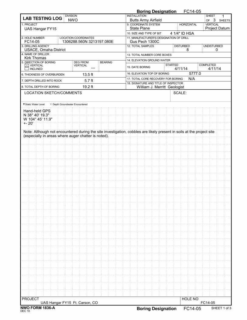
Gus Pech 1300C
18. SIGNATURE AND TITLE OF INSPECTOR
13. TOTAL NUMBER CORE BOXES
VERTICAL
Hand-held GPSN 38° 40' 19.3"W 104° 45' 11.9"+- 20'
Note: Although not encountered during the site investigation, cobbles are likely present in soils at the project site(especially in areas where auger chatter is noted).
13.5 ft
5.7 ft
19.2 ft
5777.0
STARTED
9. COORDINATE SYSTEM1. PROJECT
16. ELEVATION TOP OF BORING
USACE, Omaha District
INSTALLATION
FC14-05
4/11/14
11. MANUFACTURER'S DESIGNATION OF DRILL
5. DIRECTION OF BORING
8
HORIZONTAL
14. ELEVATION GROUND WATER
3NWO
UNDISTURBED
17. TOTAL CORE RECOVERY FOR BORING
State Plane
---
4 1/4" ID HSALOCATION COORDINATES
1OF
DEG FROMVERTICAL
DIVISION
2. HOLE NUMBER
INCLINED
10. SIZE AND TYPE OF BIT
DISTURBED
VERTICAL
SHEETSButts Army Airfield
3. DRILLING AGENCY
COMPLETED
0
15. DATE BORING
Kirk Thomas
William J. Merritt Geologist
1306288.560N 3213197.080E
4. NAME OF DRILLER
N/A
SHEET
12. TOTAL SAMPLES
LAB TESTING LOG
UAS Hangar FY15
BEARING
4/11/14
6. THICKNESS OF OVERBURDEN
7. DEPTH DRILLED INTO ROCK
8. TOTAL DEPTH OF BORING
Project Datum
Static Water Level Depth Groundwater Encountered
LOCATION SKETCH/COMMENTS SCALE:
FC14-05PROJECT
UAS Hangar FY15 Ft. Carson, COHOLE NO
NWO FORM 1836-A SHEET 1 of 3
Boring Designation FC14-05
DEC 10Boring Designation FC14-05
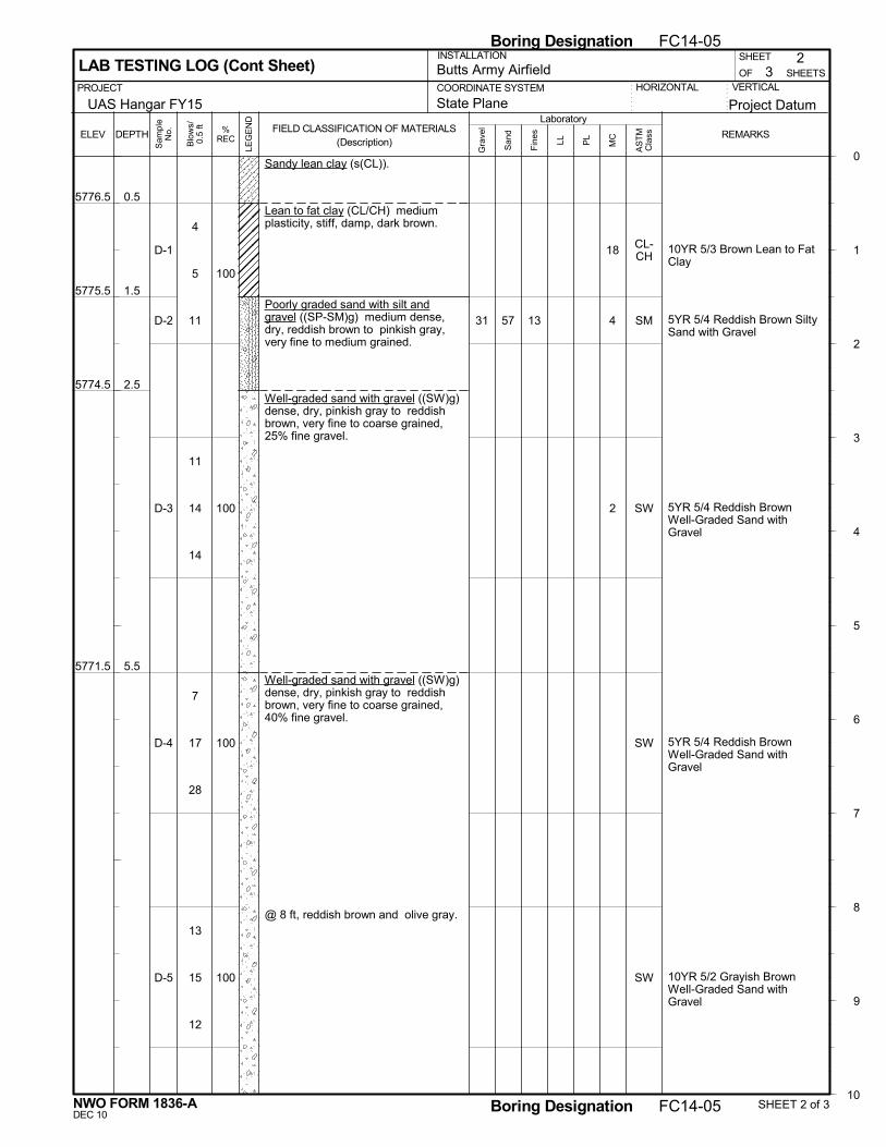
0.5
1.5
2.5
5.5
Sandy lean clay (s(CL)).
Lean to fat clay (CL/CH) mediumplasticity, stiff, damp, dark brown.
Poorly graded sand with silt andgravel ((SP-SM)g) medium dense,dry, reddish brown to pinkish gray,very fine to medium grained.
Well-graded sand with gravel ((SW)g)dense, dry, pinkish gray to reddishbrown, very fine to coarse grained,25% fine gravel.
Well-graded sand with gravel ((SW)g)dense, dry, pinkish gray to reddishbrown, very fine to coarse grained,40% fine gravel.
@ 8 ft, reddish brown and olive gray.
10YR 5/3 Brown Lean to FatClay
5YR 5/4 Reddish Brown SiltySand with Gravel
5YR 5/4 Reddish BrownWell-Graded Sand withGravel
5YR 5/4 Reddish BrownWell-Graded Sand withGravel
10YR 5/2 Grayish BrownWell-Graded Sand withGravel
57 13
5776.5
5775.5
5774.5
5771.5
31
18
4
2
CL-CH
SM
SW
SW
SW
VERTICALOF
PL
2
COORDINATE SYSTEM
Project Datum
3 SHEETS
PROJECT
Laboratory
SHEET
LL
0
1
2
3
4
5
6
7
8
9
10
DEPTHFIELD CLASSIFICATION OF MATERIALS
(Description)REMARKS
San
d
Fin
esELEV
LAB TESTING LOG (Cont Sheet)INSTALLATION
Butts Army Airfield
State PlaneUAS Hangar FY15HORIZONTAL
Gra
vel
MC
Sam
ple
No.
LEG
EN
D
%REC
Blo
ws/
0.5
ft
AS
TM
Cla
ss
NWO FORM 1836-A SHEET 2 of 3
Boring Designation FC14-05
DEC 10Boring Designation FC14-05
D-1
D-2
D-3
D-4
D-5
100
100
100
100
4
5
11
11
14
14
7
17
28
13
15
12

1838
11.5
13.5
19.2
Well-graded sand with gravel ((SW)g)dense, dry, reddish brown and olivegray, 40% fine gravel.
@ 10.5 ft, 30% fine gravel.
Lean clay (CL) no to low plasticity,stiff, dry, tan and gray, silty,weathered shale.
Shale (SHALE) dry, light tan,weathered, weak, soft, thin bedded,silty, iron oxide staining, fissile.
@ 18.5 ft, light gray to gray,competent, fissile, friable, thinbedded.
10YR 6/8 Brownish YellowLean Clay
10YR 6/6 Brownish YellowLean Clay
5765.5
5763.5
5757.8
15 CL
CL
VERTICALOF
PL
3
COORDINATE SYSTEM
Project Datum
3 SHEETS
PROJECT
Laboratory
SHEET
LL
10
11
12
13
14
15
16
17
18
19
DEPTHFIELD CLASSIFICATION OF MATERIALS
(Description)REMARKS
San
d
Fin
esELEV
LAB TESTING LOG (Cont Sheet)INSTALLATION
Butts Army Airfield
State PlaneUAS Hangar FY15HORIZONTAL
Gra
vel
MC
Sam
ple
No.
LEG
EN
D
%REC
Blo
ws/
0.5
ft
AS
TM
Cla
ss
NWO FORM 1836-A SHEET 3 of 3
Boring Designation FC14-05
DEC 10Boring Designation FC14-05
D-6
D-7
D-8
100
92
71
7
15
13
18
47
60/0.3
15
60/0.2

Gus Pech 1300C
18. SIGNATURE AND TITLE OF INSPECTOR
13. TOTAL NUMBER CORE BOXES
VERTICAL
No hand-held GPS reading
Collapse depth 8'
Note: Although not encountered during the site investigation, cobbles are likely present in soils at the project site(especially in areas where auger chatter is noted).
20 ft
0 ft
20 ft
5777.5
STARTED
9. COORDINATE SYSTEM1. PROJECT
16. ELEVATION TOP OF BORING
USACE, Omaha District
INSTALLATION
FC14-06
4/9/14
11. MANUFACTURER'S DESIGNATION OF DRILL
5. DIRECTION OF BORING
7
HORIZONTAL
14. ELEVATION GROUND WATER
3NWO
UNDISTURBED
17. TOTAL CORE RECOVERY FOR BORING
State Plane
---
4 1/4" ID HSALOCATION COORDINATES
1OF
DEG FROMVERTICAL
DIVISION
2. HOLE NUMBER
INCLINED
10. SIZE AND TYPE OF BIT
DISTURBED
VERTICAL
SHEETSButts Army Airfield
3. DRILLING AGENCY
COMPLETED
0
15. DATE BORING
Kirk Thomas
William J. Merritt Geologist
1306157.990N 3213096.360E
4. NAME OF DRILLER
N/A
SHEET
12. TOTAL SAMPLES
LAB TESTING LOG
UAS Hangar FY15
BEARING
4/9/14
6. THICKNESS OF OVERBURDEN
7. DEPTH DRILLED INTO ROCK
8. TOTAL DEPTH OF BORING
Project Datum
Static Water Level Depth Groundwater Encountered
LOCATION SKETCH/COMMENTS SCALE:
FC14-06PROJECT
UAS Hangar FY15 Ft. Carson, COHOLE NO
NWO FORM 1836-A SHEET 1 of 3
Boring Designation FC14-06
DEC 10Boring Designation FC14-06

1434
5.5
8.0
Lean clay with sand ((CL)s) lowplasticity, stiff, dry, yellowish brown tolight brown, 15% well graded sand.
Well-graded sand with gravel ((SW)g)very dense, dry, orangish brown, veryfine to coarse grained, 35% fine tocoarse gravel, gravel is subangular torounded.
Well-graded sand with silt and gravel((SW-SM)g) dense, dry, red and lightpinkish gray, very fine to coarsegrained, 15% fine gravel.
10YR 5/4 yellowish BrownLean Clay
7.5YR 6/4 Light Brown LeanClay
7.5YR 7/2 Pinkish GrayWell-Graded Sand withGravelModerate auger chatter
7.5 YR 7?2 Pinkish GrayWell-Graded sand with Siltand Gravel
60 7
5772.0
5769.5
33
8
7
1
CL
CL
SW
SW-SM
VERTICALOF
PL
2
COORDINATE SYSTEM
Project Datum
3 SHEETS
PROJECT
Laboratory
SHEET
LL
0
1
2
3
4
5
6
7
8
9
10
DEPTHFIELD CLASSIFICATION OF MATERIALS
(Description)REMARKS
San
d
Fin
esELEV
LAB TESTING LOG (Cont Sheet)INSTALLATION
Butts Army Airfield
State PlaneUAS Hangar FY15HORIZONTAL
Gra
vel
MC
Sam
ple
No.
LEG
EN
D
%REC
Blo
ws/
0.5
ft
AS
TM
Cla
ss
NWO FORM 1836-A SHEET 2 of 3
Boring Designation FC14-06
DEC 10Boring Designation FC14-06
D-1
D-2
D-3
D-4
100
100
87
87
7
9
10
5
7
15
21
30
23
20
21
14

10.5
12.0
16.0
20.0
Well-graded sand with silt and gravel((SW-SM)g) dense, dry, red and lightpinkish gray, very fine to coarsegrained, 15% fine gravel, gravel issubangular to rounded, (con't.).Well-graded sand with gravel ((SW)g)medium dense, dry, light red, 20% finegravel, subangular.
Fat clay (CH) medium to highplasticity, stiff, dry to slightly damp,tan, 10% fine sand.
Clayey sand (SC) medium dense,damp, greenish gray to tan, very fineto fine grained, 35% clay, with clay/siltlenses.
5YR 7/3 Pink well-GradedSand with Gravel
2.5 Y 6/4 Light YellowishBrown Fat Clay
10YR 6/4 Light YellowishBrown Clayey Sand
Pull augers- hole is open
5767.0
5765.5
5761.5
5757.5
SW
CH
SC
VERTICALOF
PL
3
COORDINATE SYSTEM
Project Datum
3 SHEETS
PROJECT
Laboratory
SHEET
LL
10
11
12
13
14
15
16
17
18
19
20
DEPTHFIELD CLASSIFICATION OF MATERIALS
(Description)REMARKS
San
d
Fin
esELEV
LAB TESTING LOG (Cont Sheet)INSTALLATION
Butts Army Airfield
State PlaneUAS Hangar FY15HORIZONTAL
Gra
vel
MC
Sam
ple
No.
LEG
EN
D
%REC
Blo
ws/
0.5
ft
AS
TM
Cla
ss
NWO FORM 1836-A SHEET 3 of 3
Boring Designation FC14-06
DEC 10Boring Designation FC14-06
D-5
D-6
D-7
100
100
100
10
20
8
5
5
7
5
4
7

Gus Pech 1300C
18. SIGNATURE AND TITLE OF INSPECTOR
13. TOTAL NUMBER CORE BOXES
VERTICAL
Hand-held GPSN 38° 40' 17.5"W 104° 45' 11.9"+- 37'
Offset 4' south-southeast to avoid water line.
Note: Although not encountered during the site investigation, cobbles are likely present in soils at the project site(especially in areas where auger chatter is noted).
10 ft
0 ft
10 ft
5777.0
STARTED
9. COORDINATE SYSTEM1. PROJECT
16. ELEVATION TOP OF BORING
USACE, Omaha District
INSTALLATION
FC14-07
4/9/14
11. MANUFACTURER'S DESIGNATION OF DRILL
5. DIRECTION OF BORING
4
HORIZONTAL
14. ELEVATION GROUND WATER
2NWO
UNDISTURBED
17. TOTAL CORE RECOVERY FOR BORING
State Plane
---
4 1/4" ID HSALOCATION COORDINATES
1OF
DEG FROMVERTICAL
DIVISION
2. HOLE NUMBER
INCLINED
10. SIZE AND TYPE OF BIT
DISTURBED
VERTICAL
SHEETSButts Army Airfield
3. DRILLING AGENCY
COMPLETED
0
15. DATE BORING
Kirk Thomas
William J. Merritt Geologist
1306020.730N 3213253.780E
4. NAME OF DRILLER
N/A
SHEET
12. TOTAL SAMPLES
LAB TESTING LOG
UAS Hangar FY15
BEARING
4/9/14
6. THICKNESS OF OVERBURDEN
7. DEPTH DRILLED INTO ROCK
8. TOTAL DEPTH OF BORING
Project Datum
Static Water Level Depth Groundwater Encountered
LOCATION SKETCH/COMMENTS SCALE:
FC14-07PROJECT
UAS Hangar FY15 Ft. Carson, COHOLE NO
NWO FORM 1836-A SHEET 1 of 2
Boring Designation FC14-07
DEC 10Boring Designation FC14-07

1442
7.0
10.0
Lean clay with sand ((CL)s) noplasticity, stiff, dry, light brown, 20%fine sand.
@ 3 ft, hard, reddish brown, 20% veryfine to fine sand.
Poorly graded sand with gravel((SP)g) very dense, dry, light red,angular, 20% clay, 20% very finesand.
10YR 5/2 Grayish BrownLean Clay
10YR 5/2 Grayish BrownLean Clay with Sand
10YR 6/3 Pale Brown LeanClay
Light Auger Chatter
SPT advance stopped after23 blows.10YR 5/4 Yellowish BrownPoorly Graded Sand
74
5770.0
5767.0
11
7
8
CL
CL
CL
SP
VERTICALOF
PL
2
COORDINATE SYSTEM
Project Datum
2 SHEETS
PROJECT
Laboratory
SHEET
LL
0
1
2
3
4
5
6
7
8
9
10
DEPTHFIELD CLASSIFICATION OF MATERIALS
(Description)REMARKS
San
d
Fin
esELEV
LAB TESTING LOG (Cont Sheet)INSTALLATION
Butts Army Airfield
State PlaneUAS Hangar FY15HORIZONTAL
Gra
vel
MC
Sam
ple
No.
LEG
EN
D
%REC
Blo
ws/
0.5
ft
AS
TM
Cla
ss
NWO FORM 1836-A SHEET 2 of 2
Boring Designation FC14-07
DEC 10Boring Designation FC14-07
D-1
D-2
D-3
D-4
100
13
100
100
5
7
12
11
18
22
12
10
9
60/0.3

Gus Pech 1300C
18. SIGNATURE AND TITLE OF INSPECTOR
13. TOTAL NUMBER CORE BOXES
VERTICAL
Hand-held GPSN 38° 40' 14.5"W 104° 45' 9.1"+- 41'
Moved. Boring was in construction truck turn about. Direction not indicated on log.
Note: Although not encountered during the site investigation, cobbles are likely present in soils at the project site(especially in areas where auger chatter is noted).
10 ft
0 ft
10 ft
5775.0
STARTED
9. COORDINATE SYSTEM1. PROJECT
16. ELEVATION TOP OF BORING
USACE, Omaha District
INSTALLATION
FC14-08
4/9/14
11. MANUFACTURER'S DESIGNATION OF DRILL
5. DIRECTION OF BORING
4
HORIZONTAL
14. ELEVATION GROUND WATER
2NWO
UNDISTURBED
17. TOTAL CORE RECOVERY FOR BORING
State Plane
---
4 1/4" ID HSALOCATION COORDINATES
1OF
DEG FROMVERTICAL
DIVISION
2. HOLE NUMBER
INCLINED
10. SIZE AND TYPE OF BIT
DISTURBED
VERTICAL
SHEETSButts Army Airfield
3. DRILLING AGENCY
COMPLETED
0
15. DATE BORING
Kirk Thomas
William J. Merritt Geologist
1305797.960N 3213463.570E
4. NAME OF DRILLER
N/A
SHEET
12. TOTAL SAMPLES
LAB TESTING LOG
UAS Hangar FY15
BEARING
4/9/14
6. THICKNESS OF OVERBURDEN
7. DEPTH DRILLED INTO ROCK
8. TOTAL DEPTH OF BORING
Project Datum
Static Water Level Depth Groundwater Encountered
LOCATION SKETCH/COMMENTS SCALE:
FC14-08PROJECT
UAS Hangar FY15 Ft. Carson, COHOLE NO
NWO FORM 1836-A SHEET 1 of 2
Boring Designation FC14-08
DEC 10Boring Designation FC14-08

1743
2.5
5.0
7.5
10.0
Fat clay (CH) high plasticity, very stiff,damp, brown, 10% very fine sand.
Sandy lean clay (s(CL)) no plasticity,very stiff, damp, brown, 30% very finesand.
Fat clay (CH) high plasticity, very stiff,damp, brown, 10% very fine sand.
Clayey sand with gravel ((SC)g)dense, damp, brown, very fine tocoarse grained, 20% lean clay, 10%fine gravel.
10YR 5/2 Grayish Brown FatClay
10YR 5/2 Grayish BrownLean Clay with Sand
10YR 6/2 Light BrownishGray Fat Clay
5YR 5/3 Reddish BrownClayey Sand with Gravel
74
5772.5
5770.0
5767.5
5765.0
11
9
7
CH
CL
CH
SC
VERTICALOF
PL
2
COORDINATE SYSTEM
Project Datum
2 SHEETS
PROJECT
Laboratory
SHEET
LL
0
1
2
3
4
5
6
7
8
9
10
DEPTHFIELD CLASSIFICATION OF MATERIALS
(Description)REMARKS
San
d
Fin
esELEV
LAB TESTING LOG (Cont Sheet)INSTALLATION
Butts Army Airfield
State PlaneUAS Hangar FY15HORIZONTAL
Gra
vel
MC
Sam
ple
No.
LEG
EN
D
%REC
Blo
ws/
0.5
ft
AS
TM
Cla
ss
NWO FORM 1836-A SHEET 2 of 2
Boring Designation FC14-08
DEC 10Boring Designation FC14-08
D-1
D-2
D-3
D-4
100
67
27
73
8
10
13
11
11
11
10
10
12
7
8
15
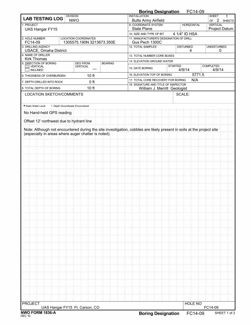
Gus Pech 1300C
18. SIGNATURE AND TITLE OF INSPECTOR
13. TOTAL NUMBER CORE BOXES
VERTICAL
No Hand-held GPS reading
Offset 12' northwest due to hydrant line
Note: Although not encountered during the site investigation, cobbles are likely present in soils at the project site(especially in areas where auger chatter is noted).
10 ft
0 ft
10 ft
5771.5
STARTED
9. COORDINATE SYSTEM1. PROJECT
16. ELEVATION TOP OF BORING
USACE, Omaha District
INSTALLATION
FC14-09
4/9/14
11. MANUFACTURER'S DESIGNATION OF DRILL
5. DIRECTION OF BORING
4
HORIZONTAL
14. ELEVATION GROUND WATER
2NWO
UNDISTURBED
17. TOTAL CORE RECOVERY FOR BORING
State Plane
---
4 1/4" ID HSALOCATION COORDINATES
1OF
DEG FROMVERTICAL
DIVISION
2. HOLE NUMBER
INCLINED
10. SIZE AND TYPE OF BIT
DISTURBED
VERTICAL
SHEETSButts Army Airfield
3. DRILLING AGENCY
COMPLETED
0
15. DATE BORING
Kirk Thomas
William J. Merritt Geologist
1305575.190N 3213673.350E
4. NAME OF DRILLER
N/A
SHEET
12. TOTAL SAMPLES
LAB TESTING LOG
UAS Hangar FY15
BEARING
4/9/14
6. THICKNESS OF OVERBURDEN
7. DEPTH DRILLED INTO ROCK
8. TOTAL DEPTH OF BORING
Project Datum
Static Water Level Depth Groundwater Encountered
LOCATION SKETCH/COMMENTS SCALE:
FC14-09PROJECT
UAS Hangar FY15 Ft. Carson, COHOLE NO
NWO FORM 1836-A SHEET 1 of 2
Boring Designation FC14-09
DEC 10Boring Designation FC14-09

1537
2.5
5.5
10.0
Lean clay with sand and gravel((CL)sg) low to medium plasticity,very stiff, dry, reddish brown, 15% finegravel, 10% sand.
Fat clay (CH) no plasticity, dense,dry, reddish brown, 10% clay.
Well-graded sand with gravel ((SW)g)very dense, dry, reddish brown, finegrained, angular, 20% gravel.
10YR 5/2 Grayish BrownLean Clay
10YR 6/3 Pale Brown FatClay
Auger chatter.5YR 6/2 Pinkish GrayWell-Graded Sand withGravelAdvance stop at 46 blows.
stop auger chatter.
5YR 6/2 Pinkish GrayWell-Graded Sand withGravel
5769.0
5766.0
5761.5
8
8
3
CL
CH
SW
SW
VERTICALOF
PL
2
COORDINATE SYSTEM
Project Datum
2 SHEETS
PROJECT
Laboratory
SHEET
LL
0
1
2
3
4
5
6
7
8
9
10
DEPTHFIELD CLASSIFICATION OF MATERIALS
(Description)REMARKS
San
d
Fin
esELEV
LAB TESTING LOG (Cont Sheet)INSTALLATION
Butts Army Airfield
State PlaneUAS Hangar FY15HORIZONTAL
Gra
vel
MC
Sam
ple
No.
LEG
EN
D
%REC
Blo
ws/
0.5
ft
AS
TM
Cla
ss
NWO FORM 1836-A SHEET 2 of 2
Boring Designation FC14-09
DEC 10Boring Designation FC14-09
D-1
D-2
D-3
D-4
100
13
75
100
10
12
10
20
14
20
60/0.4
20
20
20

Gus Pech 1300C
18. SIGNATURE AND TITLE OF INSPECTOR
13. TOTAL NUMBER CORE BOXES
VERTICAL
Hand-held GPSN 38° 40' 10.2"W 104° 45' 2.9"+- 44'
Collapse depth 10'
Note: Although not encountered during the site investigation, cobbles are likely present in soils at the project site(especially in areas where auger chatter is noted).
20 ft
0 ft
20 ft
5768.0
STARTED
9. COORDINATE SYSTEM1. PROJECT
16. ELEVATION TOP OF BORING
USACE, Omaha District
INSTALLATION
FC14-10
4/10/14
11. MANUFACTURER'S DESIGNATION OF DRILL
5. DIRECTION OF BORING
7
HORIZONTAL
14. ELEVATION GROUND WATER
3NWO
UNDISTURBED
17. TOTAL CORE RECOVERY FOR BORING
State Plane
---
4 1/4" ID HSALOCATION COORDINATES
1OF
DEG FROMVERTICAL
DIVISION
2. HOLE NUMBER
INCLINED
10. SIZE AND TYPE OF BIT
DISTURBED
VERTICAL
SHEETSButts Army Airfield
3. DRILLING AGENCY
COMPLETED
0
15. DATE BORING
Kirk Thomas
William J. Merritt Geologist
1305377.380N 3213778.710E
4. NAME OF DRILLER
N/A
SHEET
12. TOTAL SAMPLES
LAB TESTING LOG
UAS Hangar FY15
BEARING
4/10/14
6. THICKNESS OF OVERBURDEN
7. DEPTH DRILLED INTO ROCK
8. TOTAL DEPTH OF BORING
Project Datum
Static Water Level Depth Groundwater Encountered
LOCATION SKETCH/COMMENTS SCALE:
FC14-10PROJECT
UAS Hangar FY15 Ft. Carson, COHOLE NO
NWO FORM 1836-A SHEET 1 of 3
Boring Designation FC14-10
DEC 10Boring Designation FC14-10

2.0
5.0
Lean to fat clay with sand ((CL/CH)s)medium plasticity, stiff, damp, darkbrown, trace sand.
Clayey sand (SC) medium dense,dry, reddish brown, very fine grained.
Poorly graded sand with gravel((SP)g) very dense, dry, reddishbrown, very fine to coarse grained,15% fine gravel.
@ 8 ft, dense.
10YR 3/2 Very Dark GrayishBrown Lean Clay with Sand
5YR 5/6 Yellowish RedClayey Sand
Light Auger Chatter
5YR 7/2 Pinkish Gray PoorlyGraded Sand
Heavy Auger Chatter
5YR 7/2 Pinkish Gray PoorlyGraded Sand
78
44
5766.0
5763.0
17
8
2
1
CL
SC
SP
SP
VERTICALOF
PL
2
COORDINATE SYSTEM
Project Datum
3 SHEETS
PROJECT
Laboratory
SHEET
LL
0
1
2
3
4
5
6
7
8
9
10
DEPTHFIELD CLASSIFICATION OF MATERIALS
(Description)REMARKS
San
d
Fin
esELEV
LAB TESTING LOG (Cont Sheet)INSTALLATION
Butts Army Airfield
State PlaneUAS Hangar FY15HORIZONTAL
Gra
vel
MC
Sam
ple
No.
LEG
EN
D
%REC
Blo
ws/
0.5
ft
AS
TM
Cla
ss
NWO FORM 1836-A SHEET 2 of 3
Boring Designation FC14-10
DEC 10Boring Designation FC14-10
D-1
D-2
D-3
D-4
100
100
100
100
9
5
4
8
7
6
18
24
27
16
18
21

12.5
16.0
20.0
Poorly graded sand with gravel((SP)g) dense, dry, reddish brown,very fine to coarse grained, 15% finegravel, (con't.).@ 10.5 ft, very dense, 10% finegravel, fine gravel is subangular.
Poorly graded sand with silt (SP-SM)medium dense, damp, reddish brown,very fine to coarse grained, 10% silt.
Poorly graded sand with silt andgravel ((SP-SM)g) dense, dry, reddishbrown, very fine to coarse grained,20% fine gravel.
5YR 7/2 Pinkish Gray WellGraded Sand with Silt andGravelModerate Auger Chatter
5YR 4/6 Yellowish Red PoorlyGraded Sand with Silt
5YR 5/4 Reddish BrownPoorly Graded Sand with Silt
64 10
5755.5
5752.0
5748.0
26 2
4
4
SW-SM
SP-SM
SP-SM
VERTICALOF
PL
3
COORDINATE SYSTEM
Project Datum
3 SHEETS
PROJECT
Laboratory
SHEET
LL
10
11
12
13
14
15
16
17
18
19
20
DEPTHFIELD CLASSIFICATION OF MATERIALS
(Description)REMARKS
San
d
Fin
esELEV
LAB TESTING LOG (Cont Sheet)INSTALLATION
Butts Army Airfield
State PlaneUAS Hangar FY15HORIZONTAL
Gra
vel
MC
Sam
ple
No.
LEG
EN
D
%REC
Blo
ws/
0.5
ft
AS
TM
Cla
ss
NWO FORM 1836-A SHEET 3 of 3
Boring Designation FC14-10
DEC 10Boring Designation FC14-10
D-5
D-6
D-7
100
100
100
18
33
31
16
15
14
18
21
22

Gus Pech 1100C
18. SIGNATURE AND TITLE OF INSPECTOR
13. TOTAL NUMBER CORE BOXES
VERTICAL
Hand-held GPSN 38° 40' 10.5"W 104° 45' 2.0"+- 19'
Collapse depth 10'
Note: Although not encountered during the site investigation, cobbles are likely present in soils at the project site(especially in areas where auger chatter is noted).
20 ft
0 ft
20 ft
5766.5
STARTED
9. COORDINATE SYSTEM1. PROJECT
16. ELEVATION TOP OF BORING
USACE, Omaha District
INSTALLATION
FC14-11
4/10/14
11. MANUFACTURER'S DESIGNATION OF DRILL
5. DIRECTION OF BORING
7
HORIZONTAL
14. ELEVATION GROUND WATER
3NWO
UNDISTURBED
17. TOTAL CORE RECOVERY FOR BORING
State Plane
---
4 1/4" ID HSALOCATION COORDINATES
1OF
DEG FROMVERTICAL
DIVISION
2. HOLE NUMBER
INCLINED
10. SIZE AND TYPE OF BIT
DISTURBED
VERTICAL
SHEETSButts Army Airfield
3. DRILLING AGENCY
COMPLETED
0
15. DATE BORING
Kirk Thomas
William J. Merritt Geologist
1305410.860N 3213898.860E
4. NAME OF DRILLER
N/A
SHEET
12. TOTAL SAMPLES
LAB TESTING LOG
UAS Hangar FY15
BEARING
4/10/14
6. THICKNESS OF OVERBURDEN
7. DEPTH DRILLED INTO ROCK
8. TOTAL DEPTH OF BORING
Project Datum
Static Water Level Depth Groundwater Encountered
LOCATION SKETCH/COMMENTS SCALE:
FC14-11PROJECT
UAS Hangar FY15 Ft. Carson, COHOLE NO
NWO FORM 1836-A SHEET 1 of 3
Boring Designation FC14-11
DEC 10Boring Designation FC14-11

0.5
3.1
5.0
7.0
Topsoil/organics (Topsoil).
Lean to fat clay (CL) mediumplasticity, stiff, moist, brown, tracevery fine sand, trace roots.
Poorly graded sand with gravel((SP)g) very dense, dry, light red topinkish gray, fine grained, angular,30% medium to coarse sand, 8% silt.
Poorly graded sand with silt andgravel ((SP-SM)g) very dense, dry,light red to pinkish gray, fine grained,angular, 30% medium to coarse sand,8% silt.
Well-graded sand with gravel ((SW)g)very dense, dry, light red to white,very fine to coarse grained,subangular, 10% fine gravel.
10YR 5/3 Brown Lean to FatClay
3.5-5.5 Light Auger Chatter5YR 4/3 Reddish BrownPoorly Graded Sand withGravel
5.5-7 Heavy Auger Chatter
5 YR 6/2 Pinkish Gray PoorlyGraded Sand with Silt andGravel
5YR 6/2 Pinkish Gray Poorlygraded Sand with Gravel
48 8
5766.0
5763.4
5761.5
5759.5
45
19
3
1
2
CL-CH
SP
SP-SM
SP
VERTICALOF
PL
2
COORDINATE SYSTEM
Project Datum
3 SHEETS
PROJECT
Laboratory
SHEET
LL
0
1
2
3
4
5
6
7
8
9
10
DEPTHFIELD CLASSIFICATION OF MATERIALS
(Description)REMARKS
San
d
Fin
esELEV
LAB TESTING LOG (Cont Sheet)INSTALLATION
Butts Army Airfield
State PlaneUAS Hangar FY15HORIZONTAL
Gra
vel
MC
Sam
ple
No.
LEG
EN
D
%REC
Blo
ws/
0.5
ft
AS
TM
Cla
ss
NWO FORM 1836-A SHEET 2 of 3
Boring Designation FC14-11
DEC 10Boring Designation FC14-11
D-1
D-2
D-3
D-4
100
100
100
100
4
5
5
18
26
32
18
35
31
16
23
27
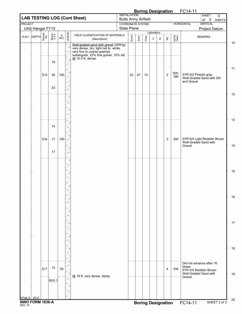
20.0
Well-graded sand with gravel ((SW)g)very dense, dry, light red to white,very fine to coarse grained,subangular, 22% fine gravel, 10% silt.@ 10.5 ft, dense.
@ 19 ft, very dense, damp.
5YR 6/2 Pinkish grayWell-Graded Sand with Siltand Gravel
5YR 6/4 Light Reddish BrownWell-Graded Sand withGravel
Did not advance after 16blows5YR 5/4 Reddish BrownWell-Graded Sand withGravel
67 10
5746.5
22 2
3
4
SW-SM
SW
SW
VERTICALOF
PL
3
COORDINATE SYSTEM
Project Datum
3 SHEETS
PROJECT
Laboratory
SHEET
LL
10
11
12
13
14
15
16
17
18
19
20
DEPTHFIELD CLASSIFICATION OF MATERIALS
(Description)REMARKS
San
d
Fin
esELEV
LAB TESTING LOG (Cont Sheet)INSTALLATION
Butts Army Airfield
State PlaneUAS Hangar FY15HORIZONTAL
Gra
vel
MC
Sam
ple
No.
LEG
EN
D
%REC
Blo
ws/
0.5
ft
AS
TM
Cla
ss
NWO FORM 1836-A SHEET 3 of 3
Boring Designation FC14-11
DEC 10Boring Designation FC14-11
D-5
D-6
D-7
100
100
50
18
26
23
14
17
17
12
60/0.1

Gus Pech 1300C
18. SIGNATURE AND TITLE OF INSPECTOR
13. TOTAL NUMBER CORE BOXES
VERTICAL
Hand-held GPSN 38° 40' 9.9"W 104° 45' 0.9"+- 40'
Collapse depth 17.2'
Note: Although not encountered during the site investigation, cobbles are likely present in soils at the project site(especially in areas where auger chatter is noted).
28 ft
0 ft
28 ft
5764.5
STARTED
9. COORDINATE SYSTEM1. PROJECT
16. ELEVATION TOP OF BORING
USACE, Omaha District
INSTALLATION
FC14-12
4/11/14
11. MANUFACTURER'S DESIGNATION OF DRILL
5. DIRECTION OF BORING
9
HORIZONTAL
14. ELEVATION GROUND WATER
4NWO
UNDISTURBED
17. TOTAL CORE RECOVERY FOR BORING
State Plane
---
4 1/4" ID HSALOCATION COORDINATES
1OF
DEG FROMVERTICAL
DIVISION
2. HOLE NUMBER
INCLINED
10. SIZE AND TYPE OF BIT
DISTURBED
VERTICAL
SHEETSButts Army Airfield
3. DRILLING AGENCY
COMPLETED
0
15. DATE BORING
Kirk Thomas
William J. Merritt Geologist
1305239.170N 3213962.810E
4. NAME OF DRILLER
N/A
SHEET
12. TOTAL SAMPLES
LAB TESTING LOG
UAS Hangar FY15
BEARING
4/11/14
6. THICKNESS OF OVERBURDEN
7. DEPTH DRILLED INTO ROCK
8. TOTAL DEPTH OF BORING
Project Datum
Static Water Level Depth Groundwater Encountered
LOCATION SKETCH/COMMENTS SCALE:
FC14-12PROJECT
UAS Hangar FY15 Ft. Carson, COHOLE NO
NWO FORM 1836-A SHEET 1 of 4
Boring Designation FC14-12
DEC 10Boring Designation FC14-12

0.5
2.5
Topsoil/organics (Topsoil).
Lean clay (CL) medium plasticity,stiff, dry, light brown.
Well-graded sand with gravel ((SW)g)very dense, dry, reddish brown, veryfine to coarse grained, 25% finegravel, gravel is angular.
@ 8 ft, 15% fine gravel.
Auger Chatter
Moderate Auger Chatter
48 7
5764.0
5762.0
45
16
2
1
1
CL
SW
SP-SM
SW
VERTICALOF
PL
2
COORDINATE SYSTEM
Project Datum
4 SHEETS
PROJECT
Laboratory
SHEET
LL
0
1
2
3
4
5
6
7
8
9
10
DEPTHFIELD CLASSIFICATION OF MATERIALS
(Description)REMARKS
San
d
Fin
esELEV
LAB TESTING LOG (Cont Sheet)INSTALLATION
Butts Army Airfield
State PlaneUAS Hangar FY15HORIZONTAL
Gra
vel
MC
Sam
ple
No.
LEG
EN
D
%REC
Blo
ws/
0.5
ft
AS
TM
Cla
ss
NWO FORM 1836-A SHEET 2 of 4
Boring Designation FC14-12
DEC 10Boring Designation FC14-12
D-1
D-2
D-3
D-4
100
87
100
56
3
4
6
18
33
28
42
40
30
26
60/0.4

12.5
Well-graded sand with gravel ((SW)g)very dense, dry, reddish brown, veryfine to coarse grained, 15% finegravel, (con't.).@ 10.5 ft, dense, 10% fine gravel.
Well-graded sand with silt and gravel((SW-SM)g) very dense, dry, reddishbrown, very fine to coarse grained,15% gravel, 17% silt.
15-20 Heavy Auger Chatter
71
67
12
17
5752.0
16
15
1
3
5
SW
SM
SM
VERTICALOF
PL
3
COORDINATE SYSTEM
Project Datum
4 SHEETS
PROJECT
Laboratory
SHEET
LL
10
11
12
13
14
15
16
17
18
19
20
DEPTHFIELD CLASSIFICATION OF MATERIALS
(Description)REMARKS
San
d
Fin
esELEV
LAB TESTING LOG (Cont Sheet)INSTALLATION
Butts Army Airfield
State PlaneUAS Hangar FY15HORIZONTAL
Gra
vel
MC
Sam
ple
No.
LEG
EN
D
%REC
Blo
ws/
0.5
ft
AS
TM
Cla
ss
NWO FORM 1836-A SHEET 3 of 4
Boring Designation FC14-12
DEC 10Boring Designation FC14-12
D-5
D-6
D-7
73
100
75
14
18
20
12
19
17
13
60/0.3
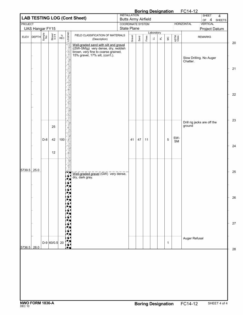
25.0
28.0
Well-graded sand with silt and gravel((SW-SM)g) very dense, dry, reddishbrown, very fine to coarse grained,15% gravel, 17% silt, (con't.).
Well-graded gravel (GW) very dense,dry, dark gray.
Slow Drilling. No AugerChatter.
Drill rig jacks are off theground
Auger Refusal
47 11
5739.5
5736.5
41 5
1
SW-SM
VERTICALOF
PL
4
COORDINATE SYSTEM
Project Datum
4 SHEETS
PROJECT
Laboratory
SHEET
LL
20
21
22
23
24
25
26
27
28
DEPTHFIELD CLASSIFICATION OF MATERIALS
(Description)REMARKS
San
d
Fin
esELEV
LAB TESTING LOG (Cont Sheet)INSTALLATION
Butts Army Airfield
State PlaneUAS Hangar FY15HORIZONTAL
Gra
vel
MC
Sam
ple
No.
LEG
EN
D
%REC
Blo
ws/
0.5
ft
AS
TM
Cla
ss
NWO FORM 1836-A SHEET 4 of 4
Boring Designation FC14-12
DEC 10Boring Designation FC14-12
D-8
D-9
100
20
25
42
12
60/0.5

BEARING
0
6. THICKNESS OF OVERBURDEN
7. DEPTH DRILLED INTO ROCK
8. TOTAL DEPTH OF BORING
3. DRILLING AGENCY
10. SIZE AND TYPE OF BIT
4. NAME OF DRILLER
OF SHEETS
5869.00 ft
29. COORDINATE SYSTEM
1/8/131/8/13
2. HOLE NUMBER
INCLINED
Depth Groundwater Encountered
1
1. PROJECT
DISTURBED
COMPLETED
Fort Carson, Butts Army AirfieldDIVISION
USACE, Omaha District
4 1/4" ID HSA
16. ELEVATION TOP OF BORING10 ft
0 ft
10 ft
FC12-30
DRILLING LOG
14. ELEVATION GROUND WATER
Gus Pech 1100C
18. SIGNATURE AND TITLE OF INSPECTOR
DEG FROMVERTICAL
---
LOCATION COORDINATES
5. DIRECTION OF BORING
15. DATE BORINGSTARTEDVERTICAL
UNDISTURBED
George A. Filpovich Geologist
Collapsed to 4.5'. Dry. Boring terminated at 10'.Backfilled with benseal and cuttings.
Note: Although not encountered during the site investigation, cobbles are likely present in soils at the project site.
Static Water Level
11. MANUFACTURER'S DESIGNATION OF DRILL
N/A
NWO
4280957.826N 479923.175E
INSTALLATION SHEET
HORIZONTAL
13. TOTAL NUMBER CORE BOXESDan Morrissey
VERTICAL
12. TOTAL SAMPLES
Aircraft Parts Storage Facility (GSAB Hangar)
4
17. TOTAL CORE RECOVERY FOR BORING
SCALE:LOCATION SKETCH/COMMENTS
Aircraft Parts Storage Facility (GSAB Hangar) Colorado Springs, COPROJECT HOLE NO
FC12-30
SHEET 1 of 2Boring Designation FC12-30
Boring Designation FC12-30
NWO FORM 1836-ADEC 10

5866.0
5860.5
5859.0
3.0
8.5
10.0
Well-graded sand with gravel ((SW)g) no plasticity, verydense, dry, reddish brown, fine to coarse grained, finegravel.
Lean clay (CL) medium plasticity, stiff, dry, brown, tracefine sand, trace fine gravel.
@ 5.5 ft, trace fine gravel.
Well-graded sand with gravel ((SW)g) no plasticity,dense, dry, reddish brown, fine to coarse grained, finegravel.
Bottom of boring at 10 ft bgs
120/0.9
10
6
32
Bulk Sample
B-12 - 4'
79
40
60
87
D-1, 0.5' -2'
D-2, 3' -4.5'
D-3, 5.5' -7'
D-4, 8.5' -10'
ELEV
2
PROJECT VERTICAL
Blo
ws/
0.5
ft
DRILLING LOG (Cont Sheet) OF
COORDINATE SYSTEM
Fort Carson, Butts Army AirfieldHORIZONTAL
SHEET
SHEETS
0
1
2
3
4
5
6
7
8
9
10
DEPTH
INSTALLATION
Aircraft Parts Storage Facility (GSAB Hangar)
2
LEG
EN
D
FIELD CLASSIFICATION OF MATERIALS(Description)
Nf REMARKS%REC
Sam
ple
Num
ber
SHEET 2 of 2Boring Designation FC12-30
Boring Designation FC12-30
NWO FORM 1836-ADEC 10
42
60
60/0.4
5
6
4
3
3
3
13
15
17

BEARING
0
6. THICKNESS OF OVERBURDEN
7. DEPTH DRILLED INTO ROCK
8. TOTAL DEPTH OF BORING
3. DRILLING AGENCY
10. SIZE AND TYPE OF BIT
4. NAME OF DRILLER
OF SHEETS
5866.00 ft
29. COORDINATE SYSTEM
1/8/131/8/13
2. HOLE NUMBER
INCLINED
Depth Groundwater Encountered
1
1. PROJECT
DISTURBED
COMPLETED
Fort Carson, Butts Army AirfieldDIVISION
USACE, Omaha District
4 1/4" ID HSA
16. ELEVATION TOP OF BORING10 ft
0 ft
10 ft
FC12-31
DRILLING LOG
14. ELEVATION GROUND WATER
Gus Pech 1100C
18. SIGNATURE AND TITLE OF INSPECTOR
DEG FROMVERTICAL
---
LOCATION COORDINATES
5. DIRECTION OF BORING
15. DATE BORINGSTARTEDVERTICAL
UNDISTURBED
George A. Filpovich Geologist
Collapsed to 4'. Dry. Boring terminated at 10'.Backfilled with benseal and cuttings.
Note: Although not encountered during the site investigation, cobbles are likely present in soils at the project site.
Static Water Level
11. MANUFACTURER'S DESIGNATION OF DRILL
N/A
NWO
4280998.619N 479797.942E
INSTALLATION SHEET
HORIZONTAL
13. TOTAL NUMBER CORE BOXESDan Morrissey
VERTICAL
12. TOTAL SAMPLES
Aircraft Parts Storage Facility (GSAB Hangar)
4
17. TOTAL CORE RECOVERY FOR BORING
SCALE:LOCATION SKETCH/COMMENTS
Aircraft Parts Storage Facility (GSAB Hangar) Colorado Springs, COPROJECT HOLE NO
FC12-31
SHEET 1 of 2Boring Designation FC12-31
Boring Designation FC12-31
NWO FORM 1836-ADEC 10

5863.0
5858.5
5856.0
3.0
7.5
10.0
Well-graded sand with gravel ((SW)g) no plasticity,medium dense, dry, reddish brown, fine to coarsegrained, fine to coarse gravel.
Lean clay (CL) medium plasticity, medium stiff, moist,brown, trace fine sand.
Well-graded sand with gravel ((SW)g) no plasticity,dense, dry, reddish brown, fine to coarse grained, finegravel.
Bottom of boring at 10 ft bgs
21
8
36
37
80
60
73
D-1, 0.5' -2'
D-2, 3' -4.5'
D-3, 5.5' -7'
D-4, 8.5' -10'
ELEV
2
PROJECT VERTICAL
Blo
ws/
0.5
ft
DRILLING LOG (Cont Sheet) OF
COORDINATE SYSTEM
Fort Carson, Butts Army AirfieldHORIZONTAL
SHEET
SHEETS
0
1
2
3
4
5
6
7
8
9
10
DEPTH
INSTALLATION
Aircraft Parts Storage Facility (GSAB Hangar)
2
LEG
EN
D
FIELD CLASSIFICATION OF MATERIALS(Description)
Nf REMARKS%REC
Sam
ple
Num
ber
SHEET 2 of 2Boring Designation FC12-31
Boring Designation FC12-31
NWO FORM 1836-ADEC 10
19
16
5
3
3
5
6
16
20
13
19
18

BEARING
0
6. THICKNESS OF OVERBURDEN
7. DEPTH DRILLED INTO ROCK
8. TOTAL DEPTH OF BORING
3. DRILLING AGENCY
10. SIZE AND TYPE OF BIT
4. NAME OF DRILLER
OF SHEETS
5865.00 ft
29. COORDINATE SYSTEM
1/8/131/8/13
2. HOLE NUMBER
INCLINED
Depth Groundwater Encountered
1
1. PROJECT
DISTURBED
COMPLETED
Fort Carson, Butts Army AirfieldDIVISION
USACE, Omaha District
4 1/4" ID HSA
16. ELEVATION TOP OF BORING10 ft
0 ft
10 ft
FC12-32
DRILLING LOG
14. ELEVATION GROUND WATER
Gus Pech 1100C
18. SIGNATURE AND TITLE OF INSPECTOR
DEG FROMVERTICAL
---
LOCATION COORDINATES
5. DIRECTION OF BORING
15. DATE BORINGSTARTEDVERTICAL
UNDISTURBED
George A. Filpovich Geologist
Collapsed to 3.5'. Dry. Boring terminated at 10'.Backfilled with benseal and cuttings.
Note: Although not encountered during the site investigation, cobbles are likely present in soils at the project site.
Static Water Level
11. MANUFACTURER'S DESIGNATION OF DRILL
N/A
NWO
4281111.068N 479853.261E
INSTALLATION SHEET
HORIZONTAL
13. TOTAL NUMBER CORE BOXESDan Morrissey
VERTICAL
12. TOTAL SAMPLES
Aircraft Parts Storage Facility (GSAB Hangar)
4
17. TOTAL CORE RECOVERY FOR BORING
SCALE:LOCATION SKETCH/COMMENTS
Aircraft Parts Storage Facility (GSAB Hangar) Colorado Springs, COPROJECT HOLE NO
FC12-32
SHEET 1 of 2Boring Designation FC12-32
Boring Designation FC12-32
NWO FORM 1836-ADEC 10

5862.0
5856.5
5855.0
3.0
8.5
10.0
Well-graded sand with gravel ((SW)g) no plasticity,dense, dry, reddish brown, fine to coarse grained, finegravel, trace coarse gravel.
Lean clay with sand ((CL)s) low plasticity, mediumdense, dry, brown, with fine to medium sand, tracecoarse sand.
Well-graded sand with gravel ((SW)g) no plasticity,dense, dry, reddish brown, fine to coarse grained, finegravel.
Bottom of boring at 10 ft bgs
33
15
16
39
80
80
87
73
D-1, 0.5' -2'
D-2, 3' -4.5'
D-3, 5.5' -7'
D-4, 8.5' -10'
ELEV
2
PROJECT VERTICAL
Blo
ws/
0.5
ft
DRILLING LOG (Cont Sheet) OF
COORDINATE SYSTEM
Fort Carson, Butts Army AirfieldHORIZONTAL
SHEET
SHEETS
0
1
2
3
4
5
6
7
8
9
10
DEPTH
INSTALLATION
Aircraft Parts Storage Facility (GSAB Hangar)
2
LEG
EN
D
FIELD CLASSIFICATION OF MATERIALS(Description)
Nf REMARKS%REC
Sam
ple
Num
ber
SHEET 2 of 2Boring Designation FC12-32
Boring Designation FC12-32
NWO FORM 1836-ADEC 10
29
22
11
7
7
8
6
8
8
11
19
20

BEARING
0
6. THICKNESS OF OVERBURDEN
7. DEPTH DRILLED INTO ROCK
8. TOTAL DEPTH OF BORING
3. DRILLING AGENCY
10. SIZE AND TYPE OF BIT
4. NAME OF DRILLER
OF SHEETS
5857.00 ft
29. COORDINATE SYSTEM
1/9/131/9/13
2. HOLE NUMBER
INCLINED
Depth Groundwater Encountered
1
1. PROJECT
DISTURBED
COMPLETED
Fort Carson, Butts Army AirfieldDIVISION
USACE, Omaha District
4 1/4" ID HSA
16. ELEVATION TOP OF BORING10 ft
0 ft
10 ft
FC12-33
DRILLING LOG
14. ELEVATION GROUND WATER
Gus Pech 1100C
18. SIGNATURE AND TITLE OF INSPECTOR
DEG FROMVERTICAL
---
LOCATION COORDINATES
5. DIRECTION OF BORING
15. DATE BORINGSTARTEDVERTICAL
UNDISTURBED
George A. Filpovich Geologist
Collapsed to 5'. Dry. Boring terminated at 10'.Backfilled with benseal and cuttings.
Note: Although not encountered during the site investigation, cobbles are likely present in soils at the project site.
Static Water Level
11. MANUFACTURER'S DESIGNATION OF DRILL
N/A
NWO
4280901.454N 479751.958E
INSTALLATION SHEET
HORIZONTAL
13. TOTAL NUMBER CORE BOXESDan Morrissey
VERTICAL
12. TOTAL SAMPLES
Aircraft Parts Storage Facility (GSAB Hangar)
4
17. TOTAL CORE RECOVERY FOR BORING
SCALE:LOCATION SKETCH/COMMENTS
Aircraft Parts Storage Facility (GSAB Hangar) Colorado Springs, COPROJECT HOLE NO
FC12-33
SHEET 1 of 2Boring Designation FC12-33
Boring Designation FC12-33
NWO FORM 1836-ADEC 10
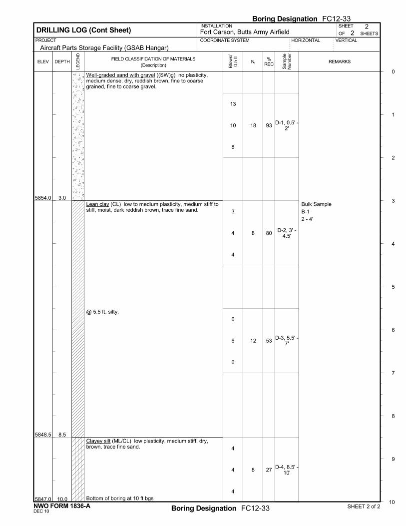
5854.0
5848.5
5847.0
3.0
8.5
10.0
Well-graded sand with gravel ((SW)g) no plasticity,medium dense, dry, reddish brown, fine to coarsegrained, fine to coarse gravel.
Lean clay (CL) low to medium plasticity, medium stiff tostiff, moist, dark reddish brown, trace fine sand.
@ 5.5 ft, silty.
Clayey silt (ML/CL) low plasticity, medium stiff, dry,brown, trace fine sand.
Bottom of boring at 10 ft bgs
18
8
12
8
Bulk Sample
B-12 - 4'
93
80
53
27
D-1, 0.5' -2'
D-2, 3' -4.5'
D-3, 5.5' -7'
D-4, 8.5' -10'
ELEV
2
PROJECT VERTICAL
Blo
ws/
0.5
ft
DRILLING LOG (Cont Sheet) OF
COORDINATE SYSTEM
Fort Carson, Butts Army AirfieldHORIZONTAL
SHEET
SHEETS
0
1
2
3
4
5
6
7
8
9
10
DEPTH
INSTALLATION
Aircraft Parts Storage Facility (GSAB Hangar)
2
LEG
EN
D
FIELD CLASSIFICATION OF MATERIALS(Description)
Nf REMARKS%REC
Sam
ple
Num
ber
SHEET 2 of 2Boring Designation FC12-33
Boring Designation FC12-33
NWO FORM 1836-ADEC 10
13
10
8
3
4
4
6
6
6
4
4
4
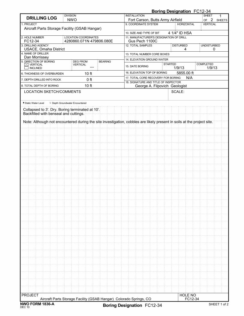
BEARING
0
6. THICKNESS OF OVERBURDEN
7. DEPTH DRILLED INTO ROCK
8. TOTAL DEPTH OF BORING
3. DRILLING AGENCY
10. SIZE AND TYPE OF BIT
4. NAME OF DRILLER
OF SHEETS
5855.00 ft
29. COORDINATE SYSTEM
1/9/131/9/13
2. HOLE NUMBER
INCLINED
Depth Groundwater Encountered
1
1. PROJECT
DISTURBED
COMPLETED
Fort Carson, Butts Army AirfieldDIVISION
USACE, Omaha District
4 1/4" ID HSA
16. ELEVATION TOP OF BORING10 ft
0 ft
10 ft
FC12-34
DRILLING LOG
14. ELEVATION GROUND WATER
Gus Pech 1100C
18. SIGNATURE AND TITLE OF INSPECTOR
DEG FROMVERTICAL
---
LOCATION COORDINATES
5. DIRECTION OF BORING
15. DATE BORINGSTARTEDVERTICAL
UNDISTURBED
George A. Filpovich Geologist
Collapsed to 3'. Dry. Boring terminated at 10'.Backfilled with benseal and cuttings.
Note: Although not encountered during the site investigation, cobbles are likely present in soils at the project site.
Static Water Level
11. MANUFACTURER'S DESIGNATION OF DRILL
N/A
NWO
4280860.071N 479806.080E
INSTALLATION SHEET
HORIZONTAL
13. TOTAL NUMBER CORE BOXESDan Morrissey
VERTICAL
12. TOTAL SAMPLES
Aircraft Parts Storage Facility (GSAB Hangar)
4
17. TOTAL CORE RECOVERY FOR BORING
SCALE:LOCATION SKETCH/COMMENTS
Aircraft Parts Storage Facility (GSAB Hangar) Colorado Springs, COPROJECT HOLE NO
FC12-34
SHEET 1 of 2Boring Designation FC12-34
Boring Designation FC12-34
NWO FORM 1836-ADEC 10
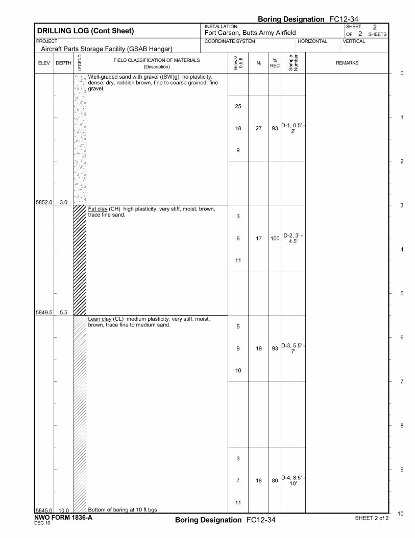
5852.0
5849.5
5845.0
3.0
5.5
10.0
Well-graded sand with gravel ((SW)g) no plasticity,dense, dry, reddish brown, fine to coarse grained, finegravel.
Fat clay (CH) high plasticity, very stiff, moist, brown,trace fine sand.
Lean clay (CL) medium plasticity, very stiff, moist,brown, trace fine to medium sand.
Bottom of boring at 10 ft bgs
27
17
19
18
93
100
93
80
D-1, 0.5' -2'
D-2, 3' -4.5'
D-3, 5.5' -7'
D-4, 8.5' -10'
ELEV
2
PROJECT VERTICAL
Blo
ws/
0.5
ft
DRILLING LOG (Cont Sheet) OF
COORDINATE SYSTEM
Fort Carson, Butts Army AirfieldHORIZONTAL
SHEET
SHEETS
0
1
2
3
4
5
6
7
8
9
10
DEPTH
INSTALLATION
Aircraft Parts Storage Facility (GSAB Hangar)
2
LEG
EN
D
FIELD CLASSIFICATION OF MATERIALS(Description)
Nf REMARKS%REC
Sam
ple
Num
ber
SHEET 2 of 2Boring Designation FC12-34
Boring Designation FC12-34
NWO FORM 1836-ADEC 10
25
18
9
3
6
11
5
9
10
3
7
11
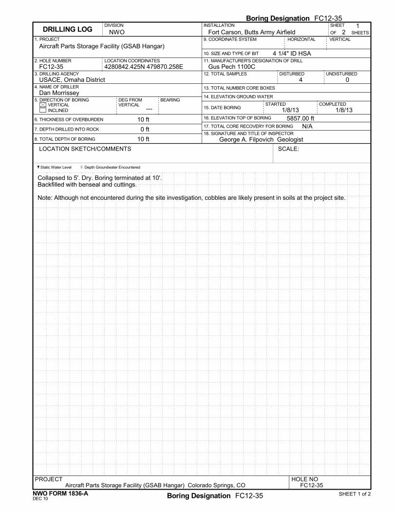
BEARING
0
6. THICKNESS OF OVERBURDEN
7. DEPTH DRILLED INTO ROCK
8. TOTAL DEPTH OF BORING
3. DRILLING AGENCY
10. SIZE AND TYPE OF BIT
4. NAME OF DRILLER
OF SHEETS
5857.00 ft
29. COORDINATE SYSTEM
1/8/131/8/13
2. HOLE NUMBER
INCLINED
Depth Groundwater Encountered
1
1. PROJECT
DISTURBED
COMPLETED
Fort Carson, Butts Army AirfieldDIVISION
USACE, Omaha District
4 1/4" ID HSA
16. ELEVATION TOP OF BORING10 ft
0 ft
10 ft
FC12-35
DRILLING LOG
14. ELEVATION GROUND WATER
Gus Pech 1100C
18. SIGNATURE AND TITLE OF INSPECTOR
DEG FROMVERTICAL
---
LOCATION COORDINATES
5. DIRECTION OF BORING
15. DATE BORINGSTARTEDVERTICAL
UNDISTURBED
George A. Filpovich Geologist
Collapsed to 5'. Dry. Boring terminated at 10'.Backfilled with benseal and cuttings.
Note: Although not encountered during the site investigation, cobbles are likely present in soils at the project site.
Static Water Level
11. MANUFACTURER'S DESIGNATION OF DRILL
N/A
NWO
4280842.425N 479870.258E
INSTALLATION SHEET
HORIZONTAL
13. TOTAL NUMBER CORE BOXESDan Morrissey
VERTICAL
12. TOTAL SAMPLES
Aircraft Parts Storage Facility (GSAB Hangar)
4
17. TOTAL CORE RECOVERY FOR BORING
SCALE:LOCATION SKETCH/COMMENTS
Aircraft Parts Storage Facility (GSAB Hangar) Colorado Springs, COPROJECT HOLE NO
FC12-35
SHEET 1 of 2Boring Designation FC12-35
Boring Designation FC12-35
NWO FORM 1836-ADEC 10
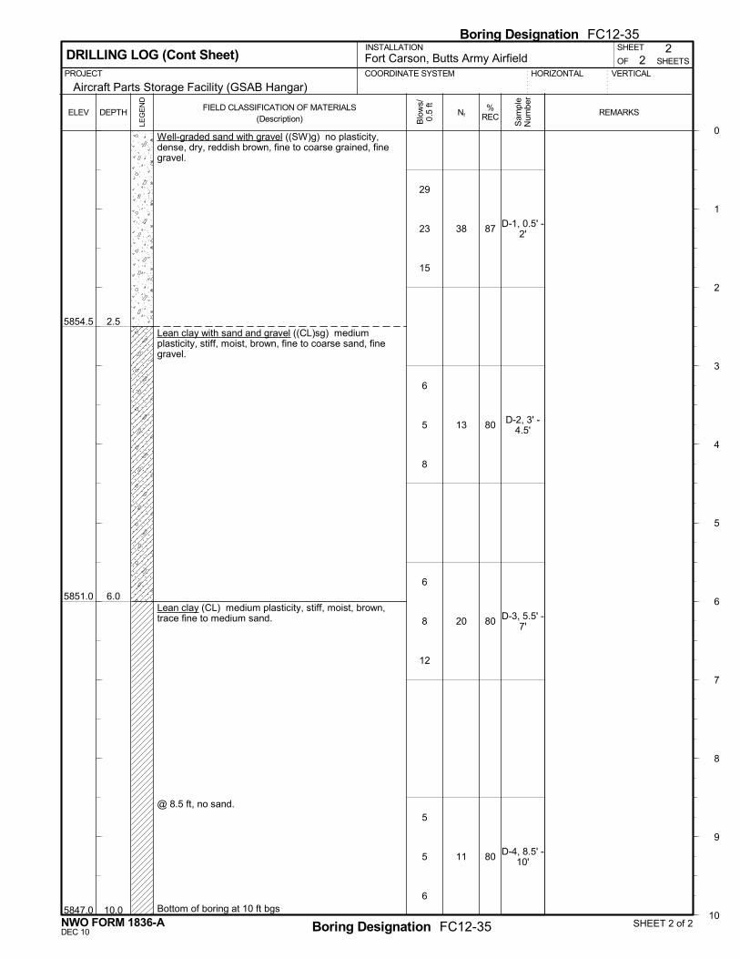
5854.5
5851.0
5847.0
2.5
6.0
10.0
Well-graded sand with gravel ((SW)g) no plasticity,dense, dry, reddish brown, fine to coarse grained, finegravel.
Lean clay with sand and gravel ((CL)sg) mediumplasticity, stiff, moist, brown, fine to coarse sand, finegravel.
Lean clay (CL) medium plasticity, stiff, moist, brown,trace fine to medium sand.
@ 8.5 ft, no sand.
Bottom of boring at 10 ft bgs
38
13
20
11
87
80
80
80
D-1, 0.5' -2'
D-2, 3' -4.5'
D-3, 5.5' -7'
D-4, 8.5' -10'
ELEV
2
PROJECT VERTICAL
Blo
ws/
0.5
ft
DRILLING LOG (Cont Sheet) OF
COORDINATE SYSTEM
Fort Carson, Butts Army AirfieldHORIZONTAL
SHEET
SHEETS
0
1
2
3
4
5
6
7
8
9
10
DEPTH
INSTALLATION
Aircraft Parts Storage Facility (GSAB Hangar)
2
LEG
EN
D
FIELD CLASSIFICATION OF MATERIALS(Description)
Nf REMARKS%REC
Sam
ple
Num
ber
SHEET 2 of 2Boring Designation FC12-35
Boring Designation FC12-35
NWO FORM 1836-ADEC 10
29
23
15
6
5
8
6
8
12
5
5
6

This page was intentionally left blank for duplex printing.

UAS Hangar - FY15 - Fort Carson, Colorado FCW9
SECTION TABLE OF CONTENTS
DIVISION 32 - EXTERIOR IMPROVEMENTS
SECTION 32 01 19
FIELD MOLDED SEALANTS FOR SEALING JOINTS IN RIGID PAVEMENTS
08/08
PART 1 GENERAL
1.1 REFERENCES 1.2 SYSTEM DESCRIPTION 1.2.1 Joint Cleaning Equipment 1.2.1.1 Tractor-Mounted Routing Tool 1.2.1.2 Concrete Saw 1.2.1.3 Sandblasting Equipment 1.2.1.4 Waterblasting Equipment 1.2.1.5 Hand Tools 1.2.2 Sealing Equipment 1.2.2.1 Cold-Applied, Single-Component Sealing Equipment 1.3 SUBMITTALS 1.4 QUALITY ASSURANCE 1.4.1 Test Requirements 1.4.2 Trial Joint Sealant Installation 1.5 DELIVERY, STORAGE, AND HANDLING 1.6 ENVIRONMENTAL REQUIREMENTS
PART 2 PRODUCTS
2.1 SEALANTS 2.2 PRIMERS 2.3 BACKUP MATERIALS
PART 3 EXECUTION
3.1 PREPARATION OF JOINTS 3.1.1 Sawing 3.1.1.1 Refacing of Joints 3.1.2 Sandblasting 3.1.3 Back-Up Material 3.1.4 Rate of Progress of Joint Preparation 3.2 PREPARATION OF SEALANT 3.2.1 Single-Component, Cold-Applied Sealants 3.3 INSTALLATION OF SEALANT 3.3.1 Time of Application 3.3.2 Sealing Joints 3.4 INSPECTION 3.4.1 Joint Cleaning 3.4.2 Joint Sealant Application Equipment 3.4.3 Joint Sealant 3.5 CLEAN-UP
-- End of Section Table of Contents --
SECTION 32 01 19 Page 1

UAS Hangar - FY15 - Fort Carson, Colorado FCW9
SECTION 32 01 19
FIELD MOLDED SEALANTS FOR SEALING JOINTS IN RIGID PAVEMENTS08/08
PART 1 GENERAL
1.1 REFERENCES
The publications listed below form a part of this specification to the extent referenced. The publications are referred to within the text by the basic designation only.
ASTM INTERNATIONAL (ASTM)
ASTM C509 (2006; R 2011) Elastomeric Cellular Preformed Gasket and Sealing Material
ASTM D5893/D5893M (2010) Cold Applied, Single Component, Chemically Curing Silicone Joint Sealant for Portland Cement Concrete Pavements
ASTM D6690 (2007) Standard Specification for Joint and Crack Sealants, Hot Applied, for Concrete and Asphalt Pavements
ASTM D7116 (2005) Standard Specification for Joint Sealants, Hot Applied, Jet Fuel Resistant Types, for Portland Cement Concrete Pavement
ASTM D789 (2007e1) Determination of Relative Viscosity and Moisture Content of Polyamide (PA)
U.S. ARMY CORPS OF ENGINEERS (USACE)
COE CRD-C 525 (1989) Corps of Engineers Test Method for Evaluation of Hot-Applied Joint Sealants for Bubbling Due to Heating
U.S. GENERAL SERVICES ADMINISTRATION (GSA)
FS SS-S-200 (Rev E; Am 1; Notice 1) Sealant, Joint, Two-Component, Jet-Blast-Resistant, Cold-Applied, for Portland Cement Concrete Pavement
1.2 SYSTEM DESCRIPTION
Machines, tools, and equipment used in the performance of the work required by this section shall be approved before the work is started maintained in satisfactory condition at all times. Submit a list of proposed equipment to be used in performance of construction work including descriptive data, 30 days prior to use on the project.
SECTION 32 01 19 Page 2

UAS Hangar - FY15 - Fort Carson, Colorado FCW9
1.2.1 Joint Cleaning Equipment
1.2.1.1 Tractor-Mounted Routing Tool
Provide a routing tool, used for removing old sealant from the joints, of such shape and dimensions and so mounted on the tractor that it will not damage the sides of the joints. The tool shall be designed so that it can be adjusted to remove the old material to varying depths as required. The use of V-shaped tools or rotary impact routing devices will not be permitted. Hand-operated spindle routing devices may be used to clean and enlarge random cracks.
1.2.1.2 Concrete Saw
Provide a self-propelled power saw, with water-cooled diamond or abrasive saw blades, for cutting joints to the depths and widths specified or for refacing joints or cleaning sawed joints where sandblasting does not provide a clean joint.
1.2.1.3 Sandblasting Equipment
Include with the sandblasting equipment an air compressor, hose, and long-wearing venturi-type nozzle of proper size, shape and opening. The maximum nozzle opening should not exceed 1/4 inch. The air compressor shall be portable and capable of furnishing not less than 150 cfm and maintaining a line pressure of not less than 90 psi at the nozzle while in use. Demonstrate compressor capability, under job conditions, before approval. The compressor shall be equipped with traps that will maintain the compressed air free of oil and water. The nozzle shall have an adjustable guide that will hold the nozzle aligned with the joint approximately 1 inch above the pavement surface. Adjust the height, angle of inclination and the size of the nozzle as necessary to secure satisfactory results.
1.2.1.4 Waterblasting Equipment
Include with the waterblasting equipment a trailer-mounted water tank, pumps, high-pressure hose, wand with safety release cutoff control, nozzle, and auxiliary water resupply equipment. Provide water tank and auxiliary resupply equipment of sufficient capacity to permit continuous operations. The nozzle shall have an adjustable guide that will hold the nozzle aligned with the joint approximately 1 inch above the pavement surface. Adjust the height, angle of inclination and the size of the nozzle as necessary to obtain satisfactory results. A pressure gauge mounted at the pump shall show at all times the pressure in psi at which the equipment is operating.
1.2.1.5 Hand Tools
Hand tools may be used, when approved, for removing defective sealant from a crack and repairing or cleaning the crack faces.
1.2.2 Sealing Equipment
1.2.2.1 Cold-Applied, Single-Component Sealing Equipment
The equipment for installing ASTM D5893/D5893M single component joint sealants shall consist of an extrusion pump, air compressor, following plate, hoses, and nozzle for transferring the sealant from the storage container into the joint opening. The dimension of the nozzle shall be
SECTION 32 01 19 Page 3

UAS Hangar - FY15 - Fort Carson, Colorado FCW9
such that the tip of the nozzle will extend into the joint to allow sealing from the bottom of the joint to the top. Maintain the initially approved equipment in good working condition, serviced in accordance with the supplier's instructions, and unaltered in any way without obtaining prior approval. Small hand-held air-powered equipment (i.e., caulking guns) may be used for small applications.
1.3 SUBMITTALS
Government approval is required for submittals with a "G" designation; submittals not having a "G" designation are for information only. When used, a designation following the "G" designation identifies the office that will review the submittal for the Government. Submit the following in accordance with Section 01 33 00 SUBMITTAL PROCEDURES:
SD-03 Product Data
Manufacturer's Recommendations; G, PO.Equipment.
SD-04 Samples
Materials; G, PO.
SD-06 Test Reports
Certified copies of the test reports; G, PO.
1.4 QUALITY ASSURANCE
1.4.1 Test Requirements
Test the joint sealant and backup or separating material for conformance with the referenced applicable material specification. Perform testing of the materials in an approved independent laboratory and submit certified copies of the test reports for approval 60 days prior to the use of the materials at the job site. Samples will be retained by the Government for possible future testing should the materials appear defective during or after application. Conformance with the requirements of the laboratory tests specified will not constitute final acceptance of the materials. Final acceptance will be based on the performance of the in-place materials. Submit samples of the materials (sealant, primer if required, and backup material), in sufficient quantity for testing and approval 60 days prior to the beginning of work. No material will be allowed to be used until it has been approved.
1.4.2 Trial Joint Sealant Installation
Prior to the cleaning and sealing of the joints for the entire project, prepare a test section at least 200 feet long using the specified materials and approved equipment, so as to demonstrate the proposed joint preparation and sealing of all types of joints in the project. Following the completion of the test section and before any other joint is sealed, inspect the test section to determine that the materials and installation meet the requirements specified. If it is determined that the materials or installation do not meet the requirements, remove the materials, and reclean and reseal the joints at no cost to the Government. When the test section meets the requirements, it may be incorporated into the permanent work and paid for at the contract unit price per linear foot for sealing
SECTION 32 01 19 Page 4

UAS Hangar - FY15 - Fort Carson, Colorado FCW9
items scheduled. Prepare and seal all other joints in the manner approved for sealing the test section.
1.5 DELIVERY, STORAGE, AND HANDLING
Inspect materials delivered to the job site for defects, unload, and store them with a minimum of handling to avoid damage. Provide storage facilities at the job site for maintaining materials at the temperatures and conditions recommended by the manufacturer.
1.6 ENVIRONMENTAL REQUIREMENTS
The ambient air temperature and the pavement temperature within the joint wall shall be a minimum of 50 degrees F and rising at the time of application of the materials. Do not apply sealant if moisture is observed in the joint.
PART 2 PRODUCTS
2.1 SEALANTS
Materials for sealing cracks in the various paved areas indicated on the drawings shall be as follows:
Area Sealing Material
All areas indicated in the drawings ASTM D5893/D5893M, Non-Sag
2.2 PRIMERS
When primers are recommended by the manufacturer of the sealant, use them in accordance with the recommendation of the manufacturer.
2.3 BACKUP MATERIALS
Provide backup material that is a compressible, nonshrinking, nonstaining, nonabsorbing material, nonreactive with the joint sealant. The material shall have a melting point at least 5 degrees F greater than the pouring temperature of the sealant being used when tested in accordance with ASTM D789. The material shall have a water absorption of not more than 5 percent of the sample weight when tested in accordance with ASTM C509. The backup material shall be 25 plus or minus 5 percent larger in diameter than the nominal width of the crack.
PART 3 EXECUTION
3.1 PREPARATION OF JOINTS
Immediately before the installation of the sealant, thoroughly clean the joints to remove all laitance, curing compound, filler, protrusions of hardened concrete, and old sealant from the sides and upper edges of the joint space to be sealed.
SECTION 32 01 19 Page 5

UAS Hangar - FY15 - Fort Carson, Colorado FCW9
3.1.1 Sawing
3.1.1.1 Refacing of Joints
Accomplish Facing of joints using a concrete saw as specified in paragraph EQUIPMENT to saw through sawed and filler-type joints to loosen and remove material until the joint is clean and open to the full specified width and depth. Stiffen the blade with a sufficient number of suitable dummy (used) blades or washers. Thoroughly clean, immediately following the sawing operation, the joint opening using a water jet to remove all saw cuttings and debris.
3.1.2 Sandblasting
The newly exposed concrete joint faces and the pavement surfaces extending a minimum of 1/2 inch from the joint edges shall be sandblasted or waterblasted clean. Use a multiple-pass technique until the surfaces are free of dust, dirt, curing compound, filler, old sealant residue, or any foreign debris that might prevent the bonding of the sealant to the concrete. After final cleaning and immediately prior to sealing, blow out the joints with compressed air and leave them completely free of debris and water.
3.1.3 Back-Up Material
When the joint opening is of a greater depth than indicated for the sealant depth, plug or seal off the lower portion of the joint opening using a back-up material to prevent the entrance of the sealant below the specified depth. Take care to ensure that the backup material is placed at the specified depth and is not stretched or twisted during installation.
3.1.4 Rate of Progress of Joint Preparation
Limit the stages of joint preparation, which include sandblasting, air pressure cleaning and placing of the back-up material to only that lineal footage that can be sealed during the same day.
3.2 PREPARATION OF SEALANT
3.2.1 Single-Component, Cold-Applied Sealants
Inspect the ASTM D5893/D5893M sealant and containers prior to use. Reject any materials that contain water, hard caking of any separated constituents, nonreversible jell, or materials that are otherwise unsatisfactory. Settlement of constituents in a soft mass that can be readily and uniformly remixed in the field with simple tools will not be cause for rejection.
3.3 INSTALLATION OF SEALANT
3.3.1 Time of Application
Seal joints immediately following final cleaning of the joint walls and following the placement of the separating or backup material. Open joints, that cannot be sealed under the conditions specified, or when rain interrupts sealing operations shall be recleaned and allowed to dry prior to installing the sealant.
SECTION 32 01 19 Page 6

UAS Hangar - FY15 - Fort Carson, Colorado FCW9
3.3.2 Sealing Joints
Immediately preceding, but not more than 50 feet ahead of the joint sealing operations, perform a final cleaning with compressed air. Fill the joints from the bottom up to 1/8 to 1/4 inch below the pavement surface. Remove and discard excess or spilled sealant from the pavement by approved methods. Install the sealant in such a manner as to prevent the formation of voids and entrapped air. In no case shall gravity methods or pouring pots be used to install the sealant material. Traffic shall not be permitted over newly sealed pavement until authorized by the Contracting Officer. When a primer is recommended by the manufacturer, apply it evenly to the joint faces in accordance with the manufacturer's instructions. Check the joints frequently to ensure that the newly installed sealant is cured to a tack-free condition within the time specified.
3.4 INSPECTION
3.4.1 Joint Cleaning
Inspect joints during the cleaning process to correct improper equipment and cleaning techniques that damage the concrete pavement in any manner. Cleaned joints will be approved prior to installation of the separating or back-up material and joint sealant.
3.4.2 Joint Sealant Application Equipment
Inspect the application equipment to ensure conformance to temperature requirements, proper proportioning and mixing (if two-component sealant) and proper installation. Evidences of bubbling, improper installation, failure to cure or set will be cause to suspend operations until causes of the deficiencies are determined and corrected.
3.4.3 Joint Sealant
Inspect the joint sealant for proper rate of cure and set, bonding to the joint walls, cohesive separation within the sealant, reversion to liquid, entrapped air and voids. Sealants exhibiting any of these deficiencies at any time prior to the final acceptance of the project shall be removed from the joint, wasted, and replaced as specified herein at no additional cost to the Government.
3.5 CLEAN-UP
Upon completion of the project, remove all unused materials from the site and leave the pavement in a clean condition.
-- End of Section --
SECTION 32 01 19 Page 7

This page was intentionally left blank for duplex printing.

UAS Hangar - FY15 - Fort Carson, Colorado FCW9
SECTION TABLE OF CONTENTS
DIVISION 32 - EXTERIOR IMPROVEMENTS
SECTION 32 05 33
LANDSCAPE ESTABLISHMENT
02/10
PART 1 GENERAL
1.1 REFERENCES 1.2 DEFINITIONS 1.2.1 Pesticide 1.2.2 Stand of Field Grass 1.3 RELATED REQUIREMENTS 1.4 SUBMITTALS 1.5 DELIVERY, STORAGE AND HANDLING 1.5.1 Delivery 1.5.2 Storage 1.5.2.1 Fertilizer, Mulch Storage 1.5.3 Handling 1.6 SUSTAINABLE DESIGN REQUIREMENTS 1.6.1 Local/Regional Materials
PART 2 PRODUCTS
2.1 POST-PLANT FERTILIZER 2.1.1 Granular Fertilizer 2.2 WATER 2.3 PESTICIDES
PART 3 EXECUTION
3.1 EXTENT OF WORK 3.1.1 Policing 3.1.2 Drainage System Maintenance 3.2 IRRIGATION ESTABLISHMENT PERIOD 3.2.1 Maintenance During the Establishment Period 3.2.2 Water Restrictions 3.2.3 Fire Hydrants 3.2.4 Final Acceptance 3.3 FIELD GRASS ESTABLISHMENT PERIOD 3.3.1 Frequency of Maintenance 3.3.2 Promotion of Growth 3.3.3 Mowing 3.3.3.1 Field Grass 3.3.4 Post-Fertilizer Application 3.3.5 Field Grass Watering 3.3.6 Replanting 3.3.7 Final Inspection and Acceptance 3.4 EXTERIOR PLANT ESTABLISHMENT PERIOD 3.4.1 Frequency of Maintenance 3.4.2 Rock Mulched Bed Maintenance 3.4.3 Slope Erosion Control Maintenance
SECTION 32 05 33 Page 1
UAS Hangar - FY15 - Fort Carson, Colorado FCW9
3.4.4 Final Inspection 3.4.4.1 Remedial Work 3.5 FIELD QUALITY CONTROL 3.5.1 Maintenance Inspection Report
-- End of Section Table of Contents --
SECTION 32 05 33 Page 2

UAS Hangar - FY15 - Fort Carson, Colorado FCW9
SECTION 32 05 33
LANDSCAPE ESTABLISHMENT02/10
PART 1 GENERAL
1.1 REFERENCES
The publications listed below form a part of this specification to the extent referenced. The publications are referred to within the text by the basic designation only.
ASTM INTERNATIONAL (ASTM)
ASTM D5851 (1995; R 2011) Planning and Implementing a Water Monitoring Program
U.S. GREEN BUILDING COUNCIL (USGBC)
LEED (2002; R 2005) Leadership in Energy and Environmental Design(tm) Green Building Rating System for New Construction (LEED-NC)
1.2 DEFINITIONS
1.2.1 Pesticide
Any substance or mixture of substances, including biological control agents, that may prevent, destroy, repel, or mitigate pests and are specifically labeled for use by the U.S. Environmental Protection Agency (EPA). Also, any substance used as a plant regulator, defoliant, disinfectant, or biocide. Examples of pesticides include fumigants, herbicides, insecticides, fungicides, nematicides, molluscicides and rodenticides.
1.2.2 Stand of Field Grass
95 percent ground cover of the established species.
1.3 RELATED REQUIREMENTS
Section 32 92 19 SEEDING applies to this section for installation of seed requirements, with additions and modifications herein.
SECTION 32 05 33 Page 3

UAS Hangar - FY15 - Fort Carson, Colorado FCW9
1.4 SUBMITTALS
Government approval is required for submittals with a "G" designation; submittals not having a "G" designation are for Contractor Quality Control approval. The following shall be submitted in accordance with Section 01 33 00 SUBMITTAL PROCEDURES:
SD-01 Preconstruction Submittals
Integrated Pest Management Plan; G-PO,
SD-03 Product Data
Local/Regional Materials; (LEED)
Submit documentation indicating distance between manufacturing facility and the project site. Indicate distance of raw material origin from the project site. Indicate relative dollar value of local/regional materials to total dollar value of products included in project.
Fertilizer; G-PO,
SD-07 Certificates
Maintenance inspection report G-PO,
SD-10 Operation and Maintenance Data
Maintenance G-PO,
1.5 DELIVERY, STORAGE AND HANDLING
1.5.1 Delivery
Deliver fertilizer, to the site in original containers bearing manufacturer's chemical analysis, name, trade name, or trademark, and indication of conformance to state and federal laws.
1.5.2 Storage
1.5.2.1 Fertilizer, Mulch Storage
Material shall be stored in designated areas. Fertilizer shall be stored in cool, dry locations away from contaminants.
SECTION 32 05 33 Page 4
UAS Hangar - FY15 - Fort Carson, Colorado FCW9
1.5.3 Handling
Do not drop or dump materials from vehicles.
1.6 SUSTAINABLE DESIGN REQUIREMENTS
1.6.1 Local/Regional Materials
Use materials or products extracted, harvested, or recovered, as well as manufactured, within a 500 mile radius from the project site, if available from a minimum of three sources.
PART 2 PRODUCTS
2.1 POST-PLANT FERTILIZER
2.1.1 Granular Fertilizer
Organic, granular controlled release fertilizer percentages of nutrients shall be determined by the contractors soils analysis.
2.2 WATER
Source of water shall be approved by the Contracting Officer, and be of suitable quality for irrigation. Contractor will be responsible for metering and paying for irrigation water during the contract period.
2.3 PESTICIDES
Submit an Integrated Pest Management Plan, including weed and pest management strategies. Use biological pest controls as approved in the Plan.
PART 3 EXECUTION
3.1 EXTENT OF WORK
Provide landscape construction maintenance to include irrigation equipment cleaning and adjustments, mowing, overseeding, fertilizing, watering, weeding, for all newly installed seeded areas, unless indicated otherwise, and at all areas inside or outside the limits of the construction that are disturbed by the Contractor's operations.
3.1.1 Policing
The Contractor shall police all seeded areas. Policing includes removal of leaves, dead vegetation, paper, trash, garbage, rocks or other debris. Policing shall extend to both sides of fencing or walls. Collected debris shall be promptly removed and disposed of at an approved disposal site.
3.1.2 Drainage System Maintenance
The Contractor shall remove all obstructions from surface and subsurface drain lines to allow water to flow unrestricted in swales, gutters, catch basins, storm drain curb inlets. Remove grates and clear debris in catch
SECTION 32 05 33 Page 5
UAS Hangar - FY15 - Fort Carson, Colorado FCW9
basins. Open drainage channels are to be maintained free of all debris and vegetation at all times. Edges of these channels shall be clear of any encroachment by vegetation.
3.2 IRRIGATION ESTABLISHMENT PERIOD
The irrigation establishment period will commence on the date that inspection by the Contracting Officer shows that the seeding and fertilizing have been accomplished and the site ready for watering.
3.2.1 Maintenance During the Establishment Period
Begin maintenance immediately after seeding has been accomplished. Watering shall consist of watering all field seeded areas with mobile truck mounted systems or large spray heads operated either manully or by controller.
3.2.2 Water Restrictions
The Contractor shall abide by state, local or other water conservation regulations in force during the establishment period. Automatic controller shall be adjusted to comply with the water conservation regulations schedule.
3.2.3 Fire Hydrants
To use a fire hydrant for irrigation, the Contractor shall obtain prior clearance from the Contracting Officer and provide the tools and connections approved for use on fire hydrants. If a fire hydrant is used, Contractor shall provide a reduced pressure backflow preventer for each connection between hose and fire hydrant. Backflow preventer used shall be tested once per month by a certified backflow preventer tester.
3.2.4 Final Acceptance
Operation and coverage test is acceptable if system operates through at least one complete cycle for areas to be irrigated and all leaks or repairs have been completed.
3.3 FIELD GRASS ESTABLISHMENT PERIOD
Field grass establishment period will commence on the date that inspection by the Contracting Officer shows that the new grass furnished under this contract has been satisfactorily installed to a 100 percent stand of coverage. The establishment period shall continue for a period of at least 120 days. or until the end of the growing season which is October 30.
3.3.1 Frequency of Maintenance
Begin maintenance immediately after grass has been installed . Inspect area a minimum of once a week during the installation and establishment period and perform needed maintenance promptly.
3.3.2 Promotion of Growth
Field grass shall be maintained in a manner that promotes proper health, growth, natural color. Grass shall have a neat uniform manicured appearance, free of bare areas, ruts, holes, weeds, pests, dead vegetation, debris, and unwanted vegetation that present an unsightly appearance. Mow, remove excess clippings, eradicate weeds, water, fertilize, overseed, and
SECTION 32 05 33 Page 6

UAS Hangar - FY15 - Fort Carson, Colorado FCW9
perform other operations necessary to promote growth, as approved by Contracting Officer and consistent with approved Integrated Pest Management Plan. Remove noxious weeds common to the area from planting areas by mechanical means.
3.3.3 Mowing
3.3.3.1 Field Grass
Field grass shall be mowed at a uniform finished height to reduce weed growth and stimulate overall grass establishment, but no less than 8" tall. The height of field grass is measured from the soil. Mowing of grass shall be performed in a manner that prevents scalping, rutting, bruising, uneven and rough cutting. Prior to mowing, all rubbish, debris, trash, leaves, rocks, paper, and limbs or branches on a grass area shall be picked up and disposed. Adjacent paved areas shall be swept/vacuumed clean.
3.3.4 Post-Fertilizer Application
Apply fertilizer in a manner that promotes health, growth, vigor, color and appearance of grass areas. The method of application, fertilizer type and frequencies shall be determined by the laboratory soil analysis results the requirements of the particular grass species. Organic fertilizer shall be used. In the event that organic fertilizer is not producing the desired effect, the Contractor shall contact the Contracting Officer for approval prior to the use of a synthetic type of fertilizer. Fertilizer shall be applied by approved methods in accordance with the manufacturer's recommendations.
3.3.5 Field Grass Watering
The Contractor shall perform irrigation in a manner that promotes the health, growth, color and appearance of cultivated vegetation and that complies with all Federal, State, and local water agencies and authorities directives. The Contractor shall be responsible to prevent over watering, water run-off, erosion, and ponding due to excessive quantities or rate of application. The Contractor shall abide by state, local or other water conservation regulations or restrictions in force during the establishment period.Irrigation controllers shall be adjusted to comply with the water conservation regulations schedule
3.3.6 Replanting
Replant in accordance with Section 32 92 19 SEEDING and within specified planting dates areas which do not have a satisfactory stand of grass.
3.3.7 Final Inspection and Acceptance
Final inspection will be make upon written request from the Contractor at least 10 days prior to the last day of the grass establishment period. Final grass acceptance will be based upon a satisfactory stand of grass.
3.4 EXTERIOR PLANT ESTABLISHMENT PERIOD
3.4.1 Frequency of Maintenance
Begin maintenance immediately after plants have been installed. Inspect
SECTION 32 05 33 Page 7
UAS Hangar - FY15 - Fort Carson, Colorado FCW9
field grass at least once a week during the installation and establishment period and perform needed maintenance promptly.
3.4.2 Rock Mulched Bed Maintenance
Rock mulched beds shall be weeded, kept pest free, grass free, and mulch levels maintained. Planter beds will not be allowed to encroach into grass areas. A definite break shall be maintained between grass areas and planter beds.
3.4.3 Slope Erosion Control Maintenance
The Contractor shall provide slope erosion control maintenance to prevent undermining of all slopes in newly landscaped. Maintenance tasks include immediate repairs to weak spots in sloped areas, and maintaining clean, clear culverts, and graded berms, and terraces to intercept and direct water flow to prevent development of large gullies and slope erosion and during periods of extended rainfall Eroded areas shall be filled with amended topsoil and replanted with the same plant species. Erosion control blankets damaged due to slope erosion shall be reinstalled.
3.4.4 Final Inspection
Final inspection will be made upon written request from the Contractor at least 10 days prior to the last day of the establishment period. Final inspection will be based upon satisfactory health and growth of plants and on the following:
3.4.4.1 Remedial Work
Remedial measures directed by the Contracting Officer to ensure plant material survival and promote healthy growth of field grasses have been completed.
3.5 FIELD QUALITY CONTROL
3.5.1 Maintenance Inspection Report
Provide maintenance inspection report to assure that landscape maintenance is being performed in accordance with the specifications and in the best interest of plant growth and survivability. Site observations shall be documented at the start of the establishment period, then quarterly following the start, and at the end of establishment period. Results of site observation visits shall be submitted to the Contracting Officer within 7 calendar days of each site observation visit.
-- End of Section --
SECTION 32 05 33 Page 8

UAS Hangar - FY15 - Fort Carson, Colorado FCW9
SECTION TABLE OF CONTENTS
DIVISION 32 - EXTERIOR IMPROVEMENTS
SECTION 32 11 10
DRAINAGE LAYER
08/08
PART 1 GENERAL
1.1 REFERENCES 1.2 SYSTEM DESCRIPTION 1.2.1 Equipment 1.2.2 Placement Equipment 1.2.3 Compaction Equipment 1.2.4 Bituminous Mixing Plant 1.2.5 Cementitious Mixing Plant 1.3 SUBMITTALS 1.4 QUALITY ASSURANCE 1.4.1 Sampling and Testing 1.4.2 Sampling 1.4.3 Test Methods 1.4.3.1 Sieve Analyses 1.4.3.2 Density Tests 1.4.3.3 Soundness Test 1.4.3.4 Los Angeles Abrasion Test 1.4.3.5 Flat or Elongated Particles Tests 1.4.3.6 Fractured Faces Tests 1.4.3.7 Bitumen Content 1.4.4 Initial Tests 1.4.5 Testing Frequency 1.4.5.1 Aggregate Layer 1.4.5.2 Stabilized Layer 1.4.6 Approval of Materials 1.4.6.1 Aggregate 1.4.6.2 Bituminous or Cementitious Materials 1.5 ENVIRONMENTAL REQUIREMENTS
PART 2 PRODUCTS
2.1 GOVERNMENT APPROVAL 2.2 AGGREGATES 2.2.1 Aggregate Quality 2.2.2 Gradation Requirements 2.3 BITUMINOUS MATERIALS 2.4 CEMENTITIOUS MATERIALS 2.5 BITUMINOUS OR CEMENT STABILIZED JOB-MIX FORMULA
PART 3 EXECUTION
3.1 STOCKPILING AGGREGATES 3.2 TEST SECTION 3.2.1 Data 3.2.2 Schedule/Evaluation
SECTION 32 11 10 Page 1

UAS Hangar - FY15 - Fort Carson, Colorado FCW9
3.2.3 Location and Size 3.2.4 Initial Testing 3.2.5 Mixing, Placement, and Compaction 3.2.6 Procedure 3.2.6.1 RDM Aggregate Drainage Layer Tests 3.2.6.2 Bituminous/Cement Stabilized Drainage Layer 3.2.7 Evaluation 3.3 PREPARATION OF UNDERLYING COURSE 3.4 TRANSPORTING MATERIAL 3.4.1 Aggregate Drainage Layer Material 3.4.2 Bituminous Stabilized Material 3.4.3 Cement Stabilized Material 3.5 PLACING 3.5.1 General Requisites 3.5.2 Placement of Stabilized Material 3.5.3 Placing Adjacent Stabilized Strips 3.5.4 Hand Spreading 3.6 COMPACTION REQUIREMENTS 3.6.1 Field Compaction 3.6.2 Number of Passes 3.6.3 Dry Density 3.7 FINISHING 3.8 CURING OF CEMENT STABILIZED MATERIAL 3.9 EDGES OF DRAINAGE LAYER 3.10 SMOOTHNESS TEST 3.11 THICKNESS CONTROL 3.12 DEFICIENCIES 3.12.1 Grade and Thickness 3.12.2 Density 3.12.3 Smoothness
-- End of Section Table of Contents --
SECTION 32 11 10 Page 2

UAS Hangar - FY15 - Fort Carson, Colorado FCW9
SECTION 32 11 10
DRAINAGE LAYER08/08
PART 1 GENERAL
1.1 REFERENCES
The publications listed below form a part of this specification to the extent referenced. The publications are referred to within the text by the basic designation only.
AMERICAN ASSOCIATION OF STATE HIGHWAY AND TRANSPORTATION OFFICIALS (AASHTO)
AASHTO M 320 (2010) Standard Specification for Performance-Graded Asphalt Binder
AASHTO T 102 (2009) Standard Method of Test for Spot Test of Asphaltic Materials
ASTM INTERNATIONAL (ASTM)
ASTM C117 (2013) Standard Test Method for Materials Finer than 75-um (No. 200) Sieve in Mineral Aggregates by Washing
ASTM C131 (2006) Standard Test Method for Resistance to Degradation of Small-Size Coarse Aggregate by Abrasion and Impact in the Los Angeles Machine
ASTM C136 (2006) Standard Test Method for Sieve Analysis of Fine and Coarse Aggregates
ASTM C150/C150M (2012) Standard Specification for Portland Cement
ASTM C29/C29M (2009) Standard Test Method for Bulk Density ("Unit Weight") and Voids in Aggregate
ASTM C595/C595M (2012) Standard Specification for Blended Hydraulic Cements
ASTM C88 (2013) Standard Test Method for Soundness of Aggregates by Use of Sodium Sulfate or Magnesium Sulfate
ASTM D1250 (2008) Standard Guide for Use of the Petroleum Measurement Tables
ASTM D140/D140M (2009) Standard Practice for Sampling Bituminous Materials
SECTION 32 11 10 Page 3

UAS Hangar - FY15 - Fort Carson, Colorado FCW9
ASTM D2172/D2172M (2011) Quantitative Extraction of Bitumen from Bituminous Paving Mixtures
ASTM D2487 (2011) Soils for Engineering Purposes (Unified Soil Classification System)
ASTM D3381/D3381M (2009a) Viscosity-Graded Asphalt Cement for Use in Pavement Construction
ASTM D4791 (2010) Flat Particles, Elongated Particles, or Flat and Elongated Particles in Coarse Aggregate
ASTM D6307 (2010) Asphalt Content of Hot Mix Asphalt by Ignition Method
ASTM D6938 (2010) Standard Test Method for In-Place Density and Water Content of Soil and Soil-Aggregate by Nuclear Methods (Shallow Depth)
ASTM D75/D75M (2013) Standard Practice for Sampling Aggregates
ASTM D946/D946M (2009a) Penetration-Graded Asphalt Cement for Use in Pavement Construction
NATIONAL INSTITUTE OF STANDARDS AND TECHNOLOGY (NIST)
NIST IR 91-4756 (1991) Laboratory Accreditation Activities in the United States
1.2 SYSTEM DESCRIPTION
Build a drainage layer under the pavements, as indicated on drawings, consisting of Rapid Draining Material (RDM) or Open Graded Material stabilized with cement or bituminous.
1.2.1 Equipment
All plant, equipment, and tools used in the performance of the work will be subject to approval before the work is started and shall be maintained in satisfactory working condition at all times.
1.2.2 Placement Equipment
Use an asphalt paving machine to place drainage layer material. Alternate methods may be used if it can be demonstrated in the test section that these methods obtain the specified results.
1.2.3 Compaction Equipment
Use a dual or single smooth 10 2000 lb- tons (min.) vibratory drum roller, which provides a maximum compactive effort without crushing the drainage layer aggregate, to compact drainage layer material.
1.2.4 Bituminous Mixing Plant
Provide a bituminous mixing plant that is an automatic or semiautomatic
SECTION 32 11 10 Page 4

UAS Hangar - FY15 - Fort Carson, Colorado FCW9
controlled, commercially manufactured unit capable of producing a bituminous stabilized aggregate mixture consistent with the job-mix formula (JMF).
1.2.5 Cementitious Mixing Plant
Provide a cementitious mixing plant that is an automatic or semiautomatic controlled, commercially manufactured unit capable of producing a cement stabilized aggregate mixture consistent with the job mix formula determined by the Government. Aggregate and cement shall be dry mixed sufficiently to prevent cement balls from forming when water is added.
1.3 SUBMITTALS
Government approval is required for submittals with a "G" designation; submittals not having a "G" designation are for information only. When used, a designation following the "G" designation identifies the office that will review the submittal for the Government. Submit the following in accordance with Section 01 33 00 SUBMITTAL PROCEDURES:
SD-03 Product Data
SD-06 Test Reports
Sampling and TestingApproval of Materials; G, POEvaluation
1.4 QUALITY ASSURANCE
1.4.1 Sampling and Testing
Submit copies of field test results within 24 hours of completion of tests. Sampling and testing are the responsibility of the Contractor to be performed by an approved commercial testing laboratory, or by the Contractor subject to approval. If the Contractor elects to establish testing facilities of its own, approval of such facilities will be based on compliance with NIST IR 91-4756, and no work requiring testing will be permitted until the Contractor's facilities have been inspected and approved. The first inspection of the facilities will be at the expense of the Government and any subsequent inspections required because of failure of the first inspection shall be at the expense of the Contractor. Such costs will be deducted from the total amount due the Contractor. Test drainage layer materials to establish compliance with the specified requirements.
1.4.2 Sampling
Take aggregate samples in accordance with ASTM D75/D75M. Take bituminous samples in accordance with ASTM D140/D140M. Take bituminous or cement stabilized mixture samples using methods approved by the Contracting Officer.
SECTION 32 11 10 Page 5

UAS Hangar - FY15 - Fort Carson, Colorado FCW9
1.4.3 Test Methods
1.4.3.1 Sieve Analyses
Make sieve analyses in accordance with ASTM C117 and ASTM C136.
1.4.3.2 Density Tests
Perform field density tests for RDM drainage layers in accordance with ASTM D6938 by Direct Transmission Method for the full depth of the lift, use ASTM D6938 to determine the moisture content of the aggregate drainage layer material. Check the calibration curves furnished with the moisture gauges along with density calibration checks as described in ASTM D6938. The calibration checks of both the density and moisture gauges shall be made by the prepared containers of material method, as described in paragraph "Calibration" of ASTM D6938, on each different type of material being tested at the beginning of a job and at intervals as directed by the Contracting Officer.
1.4.3.3 Soundness Test
Perform soundness tests in accordance with ASTM C88.
1.4.3.4 Los Angeles Abrasion Test
Perform Los Angeles abrasion tests in accordance with ASTM C131.
1.4.3.5 Flat or Elongated Particles Tests
Perform flat and/or elongated particles tests in accordance with ASTM D4791.
1.4.3.6 Fractured Faces Tests
When aggregates are supplied from crushed gravel, use approved test methods to ensure the aggregate meets the requirements for fractured faces in paragraph AGGREGATES.
1.4.3.7 Bitumen Content
Perform bitumen extraction tests in accordance with ASTM D2172/D2172M or ignition tests in accordance with ASTM D6307.
1.4.4 Initial Tests
Perform one of each of the following tests on the proposed material, prior to commencing construction, to demonstrate that the proposed material meets all specified requirements when furnished. If materials from more than one source are going to be utilized, complete the following tests for each source.
a. Sieve Analysis including No. 200 sieve size material.
b. Flat and/or elongated particles
c. Fractured Faces
d. Los Angeles abrasion.
e. Soundness.
SECTION 32 11 10 Page 6

UAS Hangar - FY15 - Fort Carson, Colorado FCW9
1.4.5 Testing Frequency
1.4.5.1 Aggregate Layer
Perform field density and moisture content tests at a rate of at least one test for every 2000 square yards of completed area and not less than one test for each day's production. Sieve analyses shall be performed at a rate of at least one test for every 6000 square yards of completed area. Perform soundness tests, Los Angeles abrasion tests, fractured faces tests and flat and/or elongated particles tests at the rate of one test for every 12,000 square yards of production.
1.4.5.2 Stabilized Layer
Perform sieve analyses on aggregates prior to addition of asphalt or portland cement, at a rate of at least one test for every 6000 square yards of completed area and not less than one test for each days production. Make extraction tests on bituminous stabilized material at the same frequency. Perform soundness tests, Los Angeles abrasion tests, fractured faces tests, and flat and/or elongated particles tests at the rate of one test for every 12,000 square yards of production.
1.4.6 Approval of Materials
Submit material sources and material test results prior to field use.
1.4.6.1 Aggregate
Select the aggregate source at least 60 days prior to field use in the test section. Tentative approval of the source will be based on certified test results to verify that materials proposed for use meet the contract requirements. Final approval of both the source and the material will be based on test section performance and tests for gradation, soundness, Los Angeles abrasion, flat and/or elongated particles tests and fractured faces tests. For aggregate drainage layer materials, perform these tests on samples taken from the completed and compacted drainage layer course within the test section. For bituminous or cement stabilized drainage layer material, perform these tests on aggregate samples taken prior to addition of bituminous or cementitious material and subsequent placement in the test section.
1.4.6.2 Bituminous or Cementitious Materials
Submit bituminous or cementitious sources and certified material test results for approval not less than 60 days prior to field use in the test section.
1.5 ENVIRONMENTAL REQUIREMENTS
Place drainage layer material when the atmospheric temperature is above 35 degrees F. Correct areas of completed drainage layer or underlying courses that are damaged by freezing, rainfall, or other weather conditions or by contamination from sediments, dust, dirt, or foreign material to meet specified requirements.
SECTION 32 11 10 Page 7

UAS Hangar - FY15 - Fort Carson, Colorado FCW9
PART 2 PRODUCTS
2.1 GOVERNMENT APPROVAL
Asphalt or cement stabilized material will require Government notification and delivery of approved materials in accordance with paragraph BITUMINOUS OR CEMENT STABILIZED JOB-MIX FORMULA.
2.2 AGGREGATES
Provide aggregates consisting of clean, sound, hard, durable, angular particles of crushed stone, crushed slag, or crushed gravel which meet the specification requirements. Slag shall be an air-cooled, blast-furnace product having a dry weight of not less than 65 pcf determined by ASTM C29/C29M. Provide aggregates free of silt and clay as defined by ASTM D2487, vegetable matter, and other objectionable materials or coatings.
2.2.1 Aggregate Quality
The aggregate shall have a soundness loss not greater than 18 percent weighted averaged at 5 cycles when tested in magnesium sulfate in accordance with ASTM C88 and a percentage of loss on abrasion not to exceed 40 after 500 revolutions as determined by ASTM C131. Determine the percentage of flat and/or elongated particles by ASTM D4791 with the following modifications: 1) The aggregates shall be separated into 2 size fractions, particles greater than 1/2 inch sieve and particles passing the 1/2 inch sieve and retained on the No. 4 sieve. 2) The percentage of flat and/or elongated particles in either fraction shall not exceed 20. 3) A flat particle is one having a ratio of width to thickness greater than 3; an elongated particle is one having a ratio of length to width greater than 3. 4) When the aggregate is supplied from more than one source, aggregate from each source shall meet the specified requirements. When the aggregate is supplied from crushed gravel it shall be manufactured from gravel particles, 90 percent of which by weight are retained on the maximum-size sieve listed in TABLE I. In the portion retained on each sieve specified, the crushed gravel shall contain at least 90 percent by weight of crushed pieces having two or more freshly fractured faces with the area of each face being at least equal to 75 percent of the smallest midsectional area of the face. When two fractures are contiguous, the angle between planes of the fractures must be at least 30 degrees in order to count as 2 fractured faces.
2.2.2 Gradation Requirements
Drainage layer aggregates shall be well graded within the limits specified in TABLE I.
TABLE I. GRADATION OF DRAINAGE LAYER MATERIAL
Percentage by Weight Passing Square-Mesh Sieve
Sieve Rapid draining OGM Designation Material (RDM) Stabilized 1-1/2 inch 100 100 1 inch 70-100 95-100 3/4 inch 55-100 --- 1/2 inch 40-80 25-80 3/8 inch 30-65 --- No. 4 10-50 0-10
SECTION 32 11 10 Page 8

UAS Hangar - FY15 - Fort Carson, Colorado FCW9
TABLE I. GRADATION OF DRAINAGE LAYER MATERIAL
Percentage by Weight Passing Square-Mesh Sieve No. 8 0-25 0-5 No. 16 0-5 ---
NOTE 1: The values are based on aggregates of uniform specific gravity, and the percentages passing the various sieves may require appropriate correction by the Contracting Officer when aggregates of varying specific gravities are used.
NOTE 3: For RDM, the coefficient of uniformity (CU) shall be greater than 3.5. (CU = D60/D10). The Contractor is responsible for adjusting the RDM gradation within the ranges listed in Table I to provide a stable construction surface for the proposed equipment and method of transporting materials or the drainage layer can be stabilize with portland cement or asphalt at no additional cost to the government, if approved during the test section.
NOTE 4: Asphalt cement or portland cement will be required to stabilize the OGM.
2.3 BITUMINOUS MATERIALS
Asphalt cement to be mixed with aggregates shall conform to ASTM D946/D946MPenetration Grade (PG) 64-22. In addition, the asphalt cement shall show a negative spot when subjected to the spot test in accordance with AASHTO T 102, using the standard naphtha specified.
2.4 CEMENTITIOUS MATERIALS
Portland cement to be mixed with aggregates shall conform to ASTM C150/C150M, Type I or II.
2.5 BITUMINOUS OR CEMENT STABILIZED JOB-MIX FORMULA
The bituminous stabilized mix shall consist of a mixture of OGM and a minimum of 2 percent asphalt cement by weight. Tolerances for bituminous stabilized material shall be maintained for field production at plus or minus 0.25 percent for asphalt cement and plus or minus 25 degrees F for mixing temperatures. The cement stabilized mix shall consist of OGM and a minimum of 200 pounds of portland cement per cubic yard with a water/cement ratio of 0.37. Based on the test section performance, the Contractor shall be responsible for adjustments (increases) in asphalt cement or portland cement quantities to ensure the stabilized drainage layer will not rut or be disturbed by the Contractor's proposed paving method. Submit a job-mix formula (JMF) with the test section report for Contracting Officer approval.
PART 3 EXECUTION
3.1 STOCKPILING AGGREGATES
Stockpile aggregates at locations designated by the Contracting Officer. Clear and level stockpile areas prior to stockpiling aggregates to prevent segregation and contamination. Aggregates obtained from different sources
SECTION 32 11 10 Page 9

UAS Hangar - FY15 - Fort Carson, Colorado FCW9
shall be stockpiled separately.
3.2 TEST SECTION
3.2.1 Data
Construct a test section to evaluate the ability to carry traffic, including placement of overlaying material and the constructability of the drainage layer including required mixing, placement, and compaction procedures. Test section data will be used by the Contracting Officer to validate the required number of compaction passes given in paragraph Compaction Requirements and the field dry density requirements for full scale production.
3.2.2 Schedule/Evaluation
Construct the test section a minimum of 30 days prior to the start of full scale production to provide sufficient time for an evaluation of the proposed materials, equipment and procedures including Government QA testing.
3.2.3 Location and Size
Place the test section inside the production paving limits. The underlying courses and subgrade preparation, required for the pavement section, shall be completed, inspected and approved in the test section prior to constructing the drainage layer. The test section shall be a minimum of 100 feet long and two full paving lanes wide side by side.
3.2.4 Initial Testing
Provide certified test results, approved by the Contracting Officer prior to the start of the test section, to verify that the materials proposed for use in the test section meet the contract requirements.
3.2.5 Mixing, Placement, and Compaction
Accomplish mixing, placement, and compaction using equipment meeting the requirements of paragraph EQUIPMENT. Compaction equipment speed shall be no greater than 1.5 mph. Start compaction from the outside edges of the paving lane and proceed to the centerline of the lift being placed. The roller shall stay a minimum of one half the roller width from the outside edge of the drainage layer being placed until the desired density is obtained. The outside edge shall then be rolled.
3.2.6 Procedure
3.2.6.1 RDM Aggregate Drainage Layer Tests
Construct the test section with aggregate in a wet state so as to establish a correlation between number of roller passes and dry density achievable during field production. Designate three separate areas within the test section, test each area for density, moisture, and gradation. Complete all testing in the middle third of the test section being placed. Conduct density and moisture content tests in accordance with ASTM D6938. Conduct sieve analysis tests on samples, taken adjacent to the density test locations. Take one set of tests (i.e. density, moisture, and sieve analysis) before the third compaction pass and after each subsequent compaction pass at three separate locations as directed by the Contracting
SECTION 32 11 10 Page 10

UAS Hangar - FY15 - Fort Carson, Colorado FCW9
Officer. Define a pass as the movement of a roller over the drainage layer area for one direction only. Compaction for the RDM shall consist of a maximum of 5 passes in the vibrating state and one final pass in the static state. Continue compaction passes and density readings until the difference between the average dry densities of any two consecutive passes is less than or equal to 1.0 pcf.
3.2.6.2 Bituminous/Cement Stabilized Drainage Layer
Construct the test section with the same equipment used for production. Designate three separate areas within the test section for sampling. Complete all testing in the middle third of the test section being placed. The Contracting Officer will perform visual examination of each sample to determine if and when crushing of aggregate occurs. Take one sample before compaction and after each subsequent compaction pass at three separate locations as directed by the Contracting Officer. Continue compaction for a maximum of 6 passes. Define a pass as the movement of a roller over the drainage layer area for one direction only. Placement procedures and equipment shall be as described herein. The Contracting Officer will determine the number of passes required for compaction from the test section.
3.2.7 Evaluation
Within 10 days of completion of the test section, submit to the Contracting Officer a Test Section Construction Report complete with all required test data and correlations. The Contracting Officer will evaluate the data and validate the required number of passes of the roller, the need for a final static pass of the roller, and provide the dry density for field density control during construction.
3.3 PREPARATION OF UNDERLYING COURSE
Prior to constructing the drainage layer, clean the underlying course of all foreign materials. During construction, the underlying course shall contain no frozen material. The underlying course shall conform to Section 32 11 16 SUBBASES FOR FLEXIBLE PAVING . Correct ruts or soft yielding spots in the underlying courses having inadequate compaction and deviations of the surface from the requirements set forth herein by loosening and removing soft or unsatisfactory material and by adding approved material, reshaping to line, and grade, and recompacting to specified density. The finished underlying course shall not be disturbed by traffic or other operations and shall be maintained in a satisfactory condition until the drainage layer is placed.
3.4 TRANSPORTING MATERIAL
3.4.1 Aggregate Drainage Layer Material
Transport aggregate drainage layer material to the site in a manner which prevents segregation and contamination of materials.
3.4.2 Bituminous Stabilized Material
Transport bituminous stabilized material from the mixing plant to the site in trucks having tight, clean, smooth beds lightly coated with an approved releasing agent to prevent adhesion of the stabilized material to the truck beds. Drain excessive releasing agent prior to loading. Cover each load with canvas or other approved material of ample size to protect the
SECTION 32 11 10 Page 11

UAS Hangar - FY15 - Fort Carson, Colorado FCW9
stabilized material from the weather and to prevent loss of heat. Loads that have crusts of cold, unworkable material or have become wet will be rejected. Hauling over freshly placed material will not be permitted.
3.4.3 Cement Stabilized Material
Transport cement stabilized material from the mixing plant to the site in trucks equipped with protective covers. Loads that have crusts of unworkable material or have become excessively wet will be rejected. Hauling over freshly placed material will not be permitted.
3.5 PLACING
3.5.1 General Requisites
Place drainage layer material on the underlying course in lifts of uniform thickness using equipment meeting the requirements of paragraph EQUIPMENT. When a compacted layer 6 inches or less in thickness is required, place the material in a single lift. When a compacted layer in excess of 6 inches is required, place the material in lifts of equal thickness. No lift shall exceed 6 inches or be less than 3 inches when compacted. The lifts when compacted after placement shall be true to the grades or levels required with the least possible surface disturbance. Where the drainage layer is placed in more than one lift, clean the previously constructed lift of loose and foreign material. Such adjustments in placing procedures or equipment shall be made to obtain true grades and minimize segregation and degradation of the drainage layer material.
3.5.2 Placement of Stabilized Material
Bituminous stabilized material having temperatures less than 175 degrees F when dumped into the asphalt paving machine will be rejected. Adjust the paving machine so that the surface of the lift being laid will be smooth and continuous without tears and pulls. Correct irregularities in alignment of the lift left by the paving machine by trimming directly behind the machine. Immediately after trimming, thoroughly compact the edges of the lift by a method approved by the Contracting Officer. Distortion of the lift during tamping will not be permitted. If more than one lift is required, offset the longitudinal joint in one lift that in the lift immediately below by at least 1 foot; however, the joint in the top layer shall be at the centerline of the pavement. Offset transverse joints in one layer by at least 2 feet from transverse joints in the previous layer. Transverse joints in adjacent strips shall be offset a minimum of 10 feet. At the end of each day's construction, form a straight transverse construction joint by cutting back into the completed work to form a true vertical face free of loose or shattered material. Remove material along construction joints not properly compacted.
3.5.3 Placing Adjacent Stabilized Strips
Place the stabilized material in consecutive adjacent strips having a minimum width of 10 feet, except where edge lanes require strips less than 10 feet to complete the area. In placing adjacent strips, the screed of the paving machine shall overlap the previously placed strip 3 to 4 inches and shall be sufficiently high so that compaction will produce a smooth, dense joint. The stabilized material placed on the edge of the previously placed strip by the paver shall be pushed back to the edge of the strip being placed. Remove and waste excess stabilized material.
SECTION 32 11 10 Page 12

UAS Hangar - FY15 - Fort Carson, Colorado FCW9
3.5.4 Hand Spreading
Spread by hand drainage layer material in areas where machine spreading is impractical. The material shall be spread uniformly in a loose layer to prevent segregation. The material shall conform to the required grade and thickness after compaction.
3.6 COMPACTION REQUIREMENTS
3.6.1 Field Compaction
Base field compaction requirements on the results of the test section, using the materials, methods, and equipment proposed for use in the work.
3.6.2 Number of Passes
Accomplish compaction using rollers meeting the requirements of paragraph EQUIPMENT and operating at a rolling speed of no greater than 1.5 miles per hour. Compact each lift of drainage material, including shoulders when specified under the shoulders, with the number of passes of the roller as follows: for RDM material use 4 passes in the vibratory state and one in the static. For cement or Bituminous stabilized OGM material use 3 passes in the vibratory state and one in the static state. The Contracting Officer will validate the number of roller passes after the test section is evaluated and before production starts.
3.6.3 Dry Density
In addition, maintain a minimum field dry density as specified by the Contracting Officer. If the required field dry density is not obtained, adjust the number of roller passes in accordance with paragraph DEFICIENCIES. Compact aggregate in a moisture state as determined in the test section. Excessive rolling resulting in crushing of aggregate particles shall be avoided. Begin compaction of bituminous stabilized material immediately when the material has cooled to 170 degrees F. Not more than 30 minutes shall elapse between the start of moist mixing of cement stabilized material and the start of field compaction, which shall be completed within 60 minutes. In all places not accessible to the rollers, compact the drainage layer material with mechanical hand operated tampers.
3.7 FINISHING
Finish the top surface of the drainage layer after final compaction, as determined from the test section. Make adjustments in rolling and finishing procedures to obtain grades and minimize segregation and degradation of the drainage layer material.
3.8 CURING OF CEMENT STABILIZED MATERIAL
Cure the completed cement stabilized drainage layer with water for a period of 12 hours following completion of compaction. Commence curing operations within 3 hours after compaction. Curing shall consist of one of the following: 1) Sprinkling the surface of the drainage layer with a fine spray of water every 2 hours for the required 12 hour period, 2) by continuously saturated burlap or cotton mats, or by continuously saturated plastic coated burlap, 3) Impervious sheet curing. Curing water shall be applied so that the cement paste on the surface of the mixture will not be eroded. Water trucks will not be permitted on the completed cement
SECTION 32 11 10 Page 13

UAS Hangar - FY15 - Fort Carson, Colorado FCW9
stabilized drainage layer. Impervious sheeting curing shall consist of all surfaces being thoroughly wetted and then completely covered with the sheeting. Sheeting shall be at least 18 inches wider than the stabilized drainage layer surface to be covered. Lay covering with light-colored side up. Lap covering not less than 12 inches; securely weight covering to prevent displacement so that it remains in contact with the surface during the specified length of curing. Coverings shall be folded down over exposed edges of slabs and secured by approved means. Sheets shall be immediately repaired or replaced if tears of holes appear during the curing period
3.9 EDGES OF DRAINAGE LAYER
Place shoulder material along the edges of the drainage layer course in a quantity that will compact to the thickness of the layer being constructed. At least 3 feet width of the shoulder shall be rolled and compacted simultaneously with the rolling and compacting of each lift of the drainage layer.
3.10 SMOOTHNESS TEST
The surface of the top lift shall not deviate more than 3/8 inch when tested with either a10 or 12 foot straightedge applied parallel with and at right angles to the centerline of the area to be paved. Correct deviations exceeding 3/8 inch in accordance with paragraph DEFICIENCIES.
3.11 THICKNESS CONTROL
The completed thickness of the drainage layer shall be within 1/2 inch of the thickness indicated. Measure thickness at intervals providing at least one measurement for each 500 square yards of drainage layer. Make measurements in test holes at least 3 inches in diameter unless the Contractor can demonstrate, for COR approval, that a steel rod pushed through the drainage layer clearly stops at the material interface. Where the measured thickness is more than 1/2 inch deficient, such areas shall be corrected in accordance with paragraph DEFICIENCIES. Where the measured thickness is 1/2 inch more than indicated, it will be considered as conforming to the requirements plus 1/2 inch, provided the surface of the drainage layer is within 1/2 inch of established grade. The average job thickness shall be the average of all job measurements as specified above but within 1/4 inch of the thickness shown on the drawings.
3.12 DEFICIENCIES
3.12.1 Grade and Thickness
Correct deficiencies in grade and thickness so that both grade and thickness tolerances are met. Thin layers of material shall not be added to the top surface of the drainage layer to meet grade or increase thickness. If the elevation of the top of the drainage layer is more than 1/2 inch above the plan grade it shall be trimmed to grade and finished in accordance with paragraph FINISHING. If the elevation of the top surface of the drainage layer is 1/2 inch or more below the required grade, the surface of the drainage layer shall be scarified to a depth of at least 3 inches, new material shall be added, and the layer shall be blended and recompacted to bring it to grade. Where the measured thickness of the drainage layer is more than 1/2 inch deficient, such areas shall be corrected by excavating to the required depth and replaced with new material to obtain a compacted lift thickness of at least 3 inches. The
SECTION 32 11 10 Page 14

UAS Hangar - FY15 - Fort Carson, Colorado FCW9
depth of required excavation shall be controlled to keep the final surface elevation within grade requirements and to preserve layer thicknesses of materials below the drainage layer.
3.12.2 Density
Density will be considered deficient if the field dry density test results are below the dry density specified by the Contracting Officer. If the densities are deficient, the layer shall be rolled with 2 additional passes of the specified roller. If the dry density is still deficient, work will be stopped until the cause of the low dry densities can be determined and reported to the Contracting Officer.
3.12.3 Smoothness
Correct deficiencies in smoothness as if they are deficiencies in grade or thickness. All tolerances for grade and thickness shall be maintained while correcting smoothness deficiencies.
-- End of Section --
SECTION 32 11 10 Page 15

This page was intentionally left blank for duplex printing.
UAS Hangar - FY15 - Fort Carson, Colorado FCW9
SECTION TABLE OF CONTENTS
DIVISION 32 - EXTERIOR IMPROVEMENTS
SECTION 32 11 16
SUBBASES FOR FLEXIBLE PAVING
08/08
PART 1 GENERAL
1.1 REFERENCES 1.2 DEFINITION 1.3 SYSTEM DESCRIPTION 1.4 SUBMITTALS 1.5 QUALITY ASSURANCE 1.5.1 Sampling 1.5.2 Tests 1.5.2.1 Sieve Analysis 1.5.2.2 Liquid Limit and Plasticity Index 1.5.2.3 Moisture-Density Determinations 1.5.2.4 Field Density Tests 1.5.2.5 Wear Test 1.5.3 Testing Frequency 1.5.3.1 Initial Tests 1.5.3.2 In-Place Tests 1.5.4 Approval of Material 1.6 ENVIRONMENTAL REQUIREMENTS
PART 2 PRODUCTS
2.1 MATERIALS 2.1.1 Subbase Course
PART 3 EXECUTION
3.1 STOCKPILING MATERIAL 3.2 PREPARATION OF UNDERLYING MATERIAL 3.3 GRADE CONTROL 3.4 MIXING AND PLACING MATERIALS 3.5 LAYER THICKNESS 3.6 COMPACTION 3.7 EDGES 3.8 SMOOTHNESS TEST 3.9 THICKNESS CONTROL 3.10 MAINTENANCE
-- End of Section Table of Contents --
SECTION 32 11 16 Page 1

UAS Hangar - FY15 - Fort Carson, Colorado FCW9
SECTION 32 11 16
SUBBASES FOR FLEXIBLE PAVING08/08
PART 1 GENERAL
1.1 REFERENCES
The publications listed below form a part of this specification to the extent referenced. The publications are referred to within the text by the basic designation only.
AMERICAN ASSOCIATION OF STATE HIGHWAY AND TRANSPORTATION OFFICIALS (AASHTO)
AASHTO T 180 (2010) Standard Method of Test for Moisture-Density Relations of Soils Using a 4.54-kg (10-lb) Rammer and a 457-mm (18-in.) Drop
AASHTO T 224 (2010) Standard Method of Test for Correction for Coarse Particles in the Soil Compaction Test
ASTM INTERNATIONAL (ASTM)
ASTM C117 (2013) Standard Test Method for Materials Finer than 75-um (No. 200) Sieve in Mineral Aggregates by Washing
ASTM C131 (2006) Standard Test Method for Resistance to Degradation of Small-Size Coarse Aggregate by Abrasion and Impact in the Los Angeles Machine
ASTM C136 (2006) Standard Test Method for Sieve Analysis of Fine and Coarse Aggregates
ASTM C29/C29M (2009) Standard Test Method for Bulk Density ("Unit Weight") and Voids in Aggregate
ASTM D1556 (2007) Density and Unit Weight of Soil in Place by the Sand-Cone Method
ASTM D1557 (2012) Standard Test Methods for Laboratory Compaction Characteristics of Soil Using Modified Effort (56,000 ft-lbf/ft3) (2700 kN-m/m3)
ASTM D2167 (2008) Density and Unit Weight of Soil in Place by the Rubber Balloon Method
ASTM D2487 (2011) Soils for Engineering Purposes (Unified Soil Classification System)
SECTION 32 11 16 Page 2
UAS Hangar - FY15 - Fort Carson, Colorado FCW9
ASTM D422 (1963; R 2007; E 2014) Particle-Size Analysis of Soils
ASTM D4318 (2010; E 2014) Liquid Limit, Plastic Limit, and Plasticity Index of Soils
ASTM D6938 (2010) Standard Test Method for In-Place Density and Water Content of Soil and Soil-Aggregate by Nuclear Methods (Shallow Depth)
ASTM D75/D75M (2013) Standard Practice for Sampling Aggregates
ASTM E11 (2009e1) Wire Cloth and Sieves for Testing Purposes
1.2 DEFINITION
Degree of compaction required is expressed as a percentage of the maximum laboratory dry density obtained by the test procedure presented in ASTM D1557 abbreviated as a percent of laboratory maximum dry density. One exception is as follows: Since ASTM D1557 applies only to soils that have 30 percent or less by weight of their particles retained on the 3/4 inch sieve, the degree of compaction for material having more than 30 percent by weight of their particles retained on the 3/4 inch sieve will be expressed as a percentage of the laboratory maximum dry density in accordance with AASHTO T 180 Method D and corrected with AASHTO T 224.
1.3 SYSTEM DESCRIPTION
All plant, equipment, and tools used in the performance of the work will be subject to approval before the work is started and shall be maintained in satisfactory working condition at all times. Submit a list of proposed equipment, including descriptive data. Provide equipment which is adequate and has the capability of producing the required compaction, meeting grade controls, thickness control, and smoothness requirements as set forth herein.
1.4 SUBMITTALS
Government approval is required for submittals with a "G" designation; submittals not having a "G" designation are for information only. When used, a designation following the "G" designation identifies the office that will review the submittal for the Government. Submit the following in accordance with Section 01 33 00 SUBMITTAL PROCEDURES:
SD-03 Product Data
Equipment
SD-06 Test Reports
Sampling and TestingField Density Tests
SECTION 32 11 16 Page 3

UAS Hangar - FY15 - Fort Carson, Colorado FCW9
1.5 QUALITY ASSURANCE
Sampling and testing are the responsibility of the Contractor, to be performed by an approved testing laboratory in accordance with Section 01 45 00.00 10 QUALITY CONTROL. Perform tests at the specified frequency. No work requiring testing will be permitted until the testing laboratory has been inspected and approved. Test the materials to establish compliance with the specified requirements.
1.5.1 Sampling
Take samples for laboratory testing in conformance with ASTM D75/D75M. When deemed necessary, the sampling will be observed by the Contracting Officer.
1.5.2 Tests
1.5.2.1 Sieve Analysis
Make sieve analysis in conformance with ASTM C117 and ASTM C136. Complete particle-size analysis of the soils in conformance with ASTM D422. Sieves shall conform to ASTM E11.
1.5.2.2 Liquid Limit and Plasticity Index
Determine liquid limit and plasticity index in accordance with ASTM D4318.
1.5.2.3 Moisture-Density Determinations
Determine the laboratory maximum dry density and optimum moisture in accordance with ASTM D1557 or AASHTO T 180, Method D and corrected with AASHTO T 224. ASTM D1557 shall be used for maximum density determinations if the material gradation contains less than 30% retained on the 19 mm (3/4 inch) sieve. AASHTO T 180, Method D shall be used for the maximum density determinations if the material gradation contains more than 30% retained on the 19 mm (3/4 inch) sieve.
1.5.2.4 Field Density Tests
Measure field density in accordance with ASTM D1556 or ASTM D6938. For the method presented in ASTM D1556, use the base plate, as shown in the drawing. For the method presented in ASTM D6938, check and adjust the calibration curves, if necessary, using only the sand cone method as described in paragraph Calibration, of the ASTM publication. Tests performed in accordance with ASTM D6938 result in a wet unit weight of soil and ASTM D6938 will be used to determine the moisture content of the soil. The calibration curves furnished with the moisture gauges shall also be checked along with density calibration checks as described in ASTM D6938. The calibration checks of both the density and moisture gauges shall be made by the prepared containers of material method, as described in paragraph Calibration, in ASTM D6938, on each different type of material to be tested at the beginning of a job and at intervals as directed.
a. Submit certified copies of test results for approval not less than 30 days before material is required for the work.
b. Submit calibration curves and related test results prior to using the device or equipment being calibrated.
SECTION 32 11 16 Page 4
UAS Hangar - FY15 - Fort Carson, Colorado FCW9
c. Submit copies of field test results within 24 hours after the tests are performed.
1.5.2.5 Wear Test
Perform wear tests in conformance with ASTM C131.
1.5.3 Testing Frequency
1.5.3.1 Initial Tests
Perform one of each of the following tests on the proposed material prior to commencing construction to demonstrate that the proposed material meets all specified requirements prior to installation.
a. Sieve Analysis including 0.02 mm size materialb. Liquid limit and plasticity indexc. Moisture-density relationshipd. Wear
1.5.3.2 In-Place Tests
Perform one of each of the following tests on samples taken from the placed and compacted subbase course. Samples shall be taken and tested at the rates indicated.
a. Perform density tests on every lift of material placed and at a frequency of one set of tests for every 500 square yards, or portion thereof, of completed area.
b. Perform sieve analysis including 0.02 mm size material on every lift of material placed and at a frequency of one sieve analysis for every 1000 square yards, or portion thereof, of material placed.
c. Perform liquid limit and plasticity index tests at the same frequency as the sieve analysis.
d. Measure the thickness of each course at intervals providing at least one measurement for each 500 square yards or part thereof. The thickness measurement shall be made by test holes, at least 3 inches in diameter through the course.
1.5.4 Approval of Material
Select the source of materials 30 days prior to the time the material will be required in the work. Tentative approval will be based on initial test results. Final approval of the materials will be based on tests for gradation, liquid limit, and plasticity index performed on samples taken from the completed and compacted course.
1.6 ENVIRONMENTAL REQUIREMENTS
Perform construction when the atmospheric temperature is above 35 degrees F. When the temperature falls below 35 degrees F, protect all completed areas by approved methods against detrimental effects of freezing. Correct completed areas damaged by freezing, rainfall, or other weather conditions to meet specified requirements.
SECTION 32 11 16 Page 5

UAS Hangar - FY15 - Fort Carson, Colorado FCW9
PART 2 PRODUCTS
2.1 MATERIALS
2.1.1 Subbase Course
Provide aggregates consisting of crushed stone, gravel, sand, or other sound, durable, approved materials processed and blended or naturally combined. Provide aggregates which are durable and sound, free from lumps and balls of clay, organic matter, objectionable coatings, and other foreign material. Material retained on the No. 4 sieve shall have a percentage of wear not to exceed 50 percent after 500 revolutions when tested as specified in ASTM C131. Aggregate shall be reasonably uniform in density and quality. Aggregates shall have a maximum size of 2 inch and shall be within the limits specified as follows:
Maximum Allowable Percentage by WeightPassing Square-Mesh Sieve
_______________________________________
Sieve Designation No. 1 ________________________________________________________________________
No. 10 50 No. 200 8
Particles having diameters less than 0.0008 inches shall not be in excess of 3 percent by weight of the total sample tested as determined in accordance with ASTM D422. The portion of any blended component and of the completed course passing the No. 40 sieve shall be either nonplastic or shall have a liquid limit not greater than 25 and a plasticity index not greater than 5.
PART 3 EXECUTION
3.1 STOCKPILING MATERIAL
Prior to stockpiling of material, clear and level storage sites. Stockpile all materials, including approved material available from excavation and grading, in the manner and at the locations designated. Aggregates shall be stockpiled on the cleared and leveled areas designated by the Contracting Officer to prevent segregation. Materials obtained from different sources shall be stockpiled separately.
3.2 PREPARATION OF UNDERLYING MATERIAL
Prior to constructing the subbase course, clean the underlying course or subgrade of all foreign substances. The surface of the underlying course or subgrade shall meet specified compaction and surface tolerances. Correct ruts, or soft yielding spots, in the underlying courses, subgrade areas having inadequate compaction, and deviations of the surface from the specified requirements, by loosening and removing soft or unsatisfactory material and by adding approved material, reshaping to line and grade, and recompacting to specified density requirements. For cohesionless underlying courses or subgrades containing sands or gravels, as defined in ASTM D2487, the surface shall be stabilized prior to placement of the overlying course. Accomplish stabilization by mixing the overlying course material into the underlying course, and compacting by approved methods. The stabilized material shall be considered as part of the underlying
SECTION 32 11 16 Page 6

UAS Hangar - FY15 - Fort Carson, Colorado FCW9
course and shall meet all requirements for the underlying course. The finished underlying course shall not be disturbed by traffic or other operations and shall be maintained in a satisfactory condition until the overlying course is placed.
3.3 GRADE CONTROL
The finished and completed course shall conform to the lines, grades, and cross sections shown. The lines, grades, and cross sections shown shall be maintained by means of line and grade stakes placed by the Contractor at the work site.
3.4 MIXING AND PLACING MATERIALS
Mix and place the materials to obtain uniformity of the material at the water content specified. Make such adjustments in mixing or placing procedures or in equipment as may be directed to obtain the true grades, to minimize segregation and degradation, to reduce or accelerate loss or increase of water, and to insure a satisfactory subbase course.
3.5 LAYER THICKNESS
The compacted thickness of the completed course shall be as indicated. When a compacted layer of 6 inches is specified, the material may be placed in a single layer; when a compacted thickness of more than 6 inches is required, no layer shall be thicker than 6 inches nor be thinner than 3 inches when compacted.
3.6 COMPACTION
Compact each layer of the material, as specified, with approved compaction equipment. Maintain water content during the compaction procedure to within plus or minus 2 percent of optimum water content, as determined from laboratory tests, as specified in paragraph SAMPLING AND TESTING. In all places not accessible to the rollers, compact the mixture with hand-operated power tampers. Compaction of the subbase shall continue until each layer is compacted through the full depth to at least 100 percent of laboratory maximum density. Make such adjustments in compacting or finishing procedures as may be directed to obtain true grades, to minimize segregation and degradation, to reduce or increase water content, and to ensure a satisfactory subbase course. Any materials that are found to be unsatisfactory shall be removed and replaced with satisfactory material or reworked, as directed, to meet the requirements of this specification.
3.7 EDGES
Place approved material along the edges of the subbase course in such quantity as will compact to the thickness of the course being constructed. When the course is being constructed in two or more layers, at least a 1 foot width of the shoulder shall be rolled and compacted simultaneously with the rolling and compacting of each layer of the subbase course, as directed.
3.8 SMOOTHNESS TEST
The surface of the top layer shall show no deviations in excess of 3/8 inch when tested with a 12 foot straightedge. Take measurements in successive positions parallel to the centerline of the area to be paved. Measurements
SECTION 32 11 16 Page 7
UAS Hangar - FY15 - Fort Carson, Colorado FCW9
shall also be taken perpendicular to the centerline at 50 foot intervals. Correct deviations exceeding this amount by removing material and replacing with new material, or by reworking existing material and compacting it to meet these specifications.
3.9 THICKNESS CONTROL
The completed thickness of the course(s) shall be in accordance with the thickness and grade indicated on the drawings. The completed course shall not be more than 1/2 inch deficient in thickness nor more than 1/2 inch above or below the established grade. Where any of these tolerances are exceeded, correct such areas by scarifying, adding new material of proper gradation or removing material, and compacting, as directed. Where the measured thickness is 1/2 inch or more thicker than shown, the course will be considered as conforming with the specified thickness requirements plus 1/2 inch. The average job thickness shall be the average of the job measurements as specified above but within 1/4 inch of the thickness shown.
3.10 MAINTENANCE
Maintain the completed course in a satisfactory condition until accepted.
-- End of Section --
SECTION 32 11 16 Page 8

UAS Hangar - FY15 - Fort Carson, Colorado FCW9
SECTION TABLE OF CONTENTS
DIVISION 32 - EXTERIOR IMPROVEMENTS
SECTION 32 11 16.01
SUBBASE AND RIGID PAVEMENT BASE COURSE FOR NON-AIRFIELD PAVEMENTS
08/08
PART 1 GENERAL
1.1 REFERENCES 1.2 DEFINITION 1.3 SYSTEM DESCRIPTION 1.4 SUBMITTALS 1.5 QUALITY ASSURANCE 1.5.1 Sampling 1.5.2 Tests 1.5.2.1 Sieve Analysis 1.5.2.2 Liquid Limit and Plasticity Index 1.5.2.3 Moisture-Density Determinations 1.5.2.4 Field Density Tests 1.5.2.5 Wear Test 1.5.3 Testing Frequency 1.5.3.1 Initial Tests 1.5.3.2 In-Place Tests 1.5.4 Approval of Material 1.6 ENVIRONMENTAL REQUIREMENTS
PART 2 PRODUCTS
2.1 MATERIALS 2.1.1 Subbase Course 2.1.2 Rigid Pavement Base Course
PART 3 EXECUTION
3.1 OPERATION OF AGGREGATE SOURCES 3.2 PREPARATION OF UNDERLYING MATERIAL 3.3 GRADE CONTROL 3.4 MIXING AND PLACING MATERIALS 3.5 LAYER THICKNESS 3.6 COMPACTION 3.7 EDGES 3.8 SMOOTHNESS TEST 3.9 THICKNESS CONTROL 3.10 MAINTENANCE
-- End of Section Table of Contents --
SECTION 32 11 16.01 Page 1

UAS Hangar - FY15 - Fort Carson, Colorado FCW9
SECTION 32 11 16.01
SUBBASE AND RIGID PAVEMENT BASE COURSE FOR NON-AIRFIELD PAVEMENTS08/08
PART 1 GENERAL
1.1 REFERENCES
The publications listed below form a part of this specification to the extent referenced. The publications are referred to within the text by the basic designation only.
AMERICAN ASSOCIATION OF STATE HIGHWAY AND TRANSPORTATION OFFICIALS (AASHTO)
AASHTO T 180 (2010) Standard Method of Test for Moisture-Density Relations of Soils Using a 4.54-kg (10-lb) Rammer and a 457-mm (18-in.) Drop
AASHTO T 224 (2010) Standard Method of Test for Correction for Coarse Particles in the Soil Compaction Test
ASTM INTERNATIONAL (ASTM)
ASTM C 117 (2004) Standard Test Method for Materials Finer than 75-um (No. 200) Sieve in Mineral Aggregates by Washing
ASTM C 131 (2006)Standard Test Method for Resistance to Degradation of Small-Size Coarse Aggregate by Abrasion and Impact in the Los Angeles Machine
ASTM C 136 (2006) Standard Test Method for Sieve Analysis of Fine and Coarse Aggregates
ASTM C 29/C 29M (2007) Standard Test Method for Bulk Density ("Unit Weight") and Voids in Aggregate
ASTM D 1556 (2007) Density and Unit Weight of Soil in Place by the Sand-Cone Method
ASTM D 1557 (2007) Standard Test Methods for Laboratory Compaction Characteristics of Soil Using Modified Effort (56,000 ft-lbf/ft3) (2700 kN-m/m3)
ASTM D 2167 (1994; R 2001) Density and Unit Weight of Soil in Place by the Rubber Balloon Method
ASTM D 2487 (2006) Soils for Engineering Purposes (Unified Soil Classification System)
SECTION 32 11 16.01 Page 2
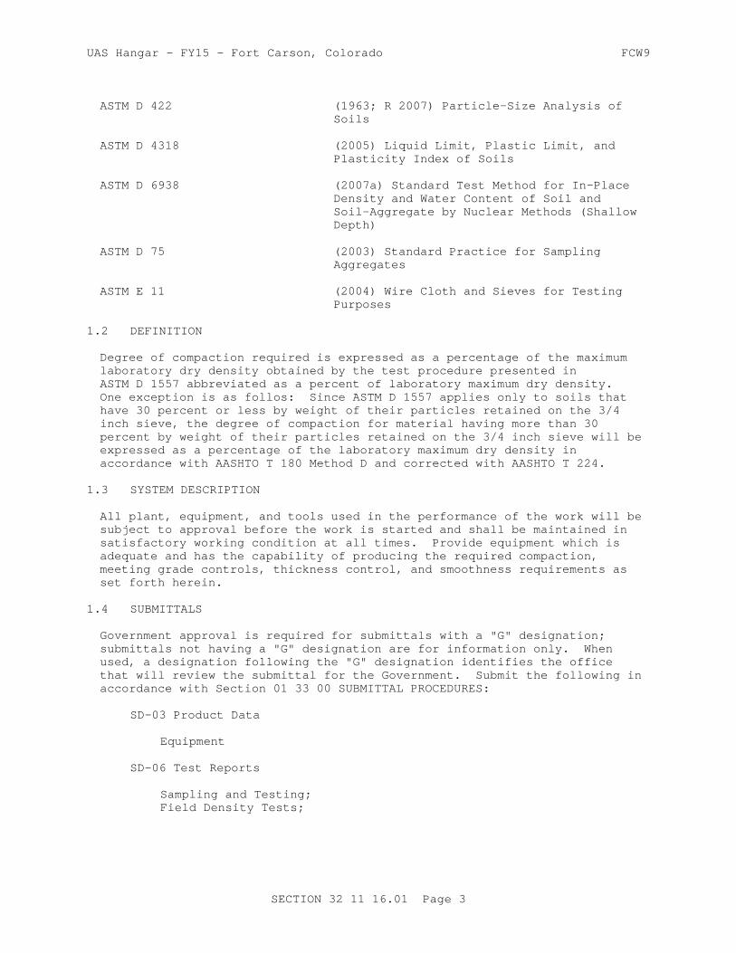
UAS Hangar - FY15 - Fort Carson, Colorado FCW9
ASTM D 422 (1963; R 2007) Particle-Size Analysis of Soils
ASTM D 4318 (2005) Liquid Limit, Plastic Limit, and Plasticity Index of Soils
ASTM D 6938 (2007a) Standard Test Method for In-Place Density and Water Content of Soil and Soil-Aggregate by Nuclear Methods (Shallow Depth)
ASTM D 75 (2003) Standard Practice for Sampling Aggregates
ASTM E 11 (2004) Wire Cloth and Sieves for Testing Purposes
1.2 DEFINITION
Degree of compaction required is expressed as a percentage of the maximum laboratory dry density obtained by the test procedure presented in ASTM D 1557 abbreviated as a percent of laboratory maximum dry density. One exception is as follos: Since ASTM D 1557 applies only to soils that have 30 percent or less by weight of their particles retained on the 3/4 inch sieve, the degree of compaction for material having more than 30 percent by weight of their particles retained on the 3/4 inch sieve will be expressed as a percentage of the laboratory maximum dry density in accordance with AASHTO T 180 Method D and corrected with AASHTO T 224.
1.3 SYSTEM DESCRIPTION
All plant, equipment, and tools used in the performance of the work will be subject to approval before the work is started and shall be maintained in satisfactory working condition at all times. Provide equipment which is adequate and has the capability of producing the required compaction, meeting grade controls, thickness control, and smoothness requirements as set forth herein.
1.4 SUBMITTALS
Government approval is required for submittals with a "G" designation; submittals not having a "G" designation are for information only. When used, a designation following the "G" designation identifies the office that will review the submittal for the Government. Submit the following in accordance with Section 01 33 00 SUBMITTAL PROCEDURES:
SD-03 Product Data
Equipment
SD-06 Test Reports
Sampling and Testing; Field Density Tests;
SECTION 32 11 16.01 Page 3

UAS Hangar - FY15 - Fort Carson, Colorado FCW9
1.5 QUALITY ASSURANCE
Sampling and testing are the responsibility of the Contractor, to be performed by an approved testing laboratory in accordance with Section 01 45 00.00 10 QUALITY CONTROL. Perform tests at the specified frequency. No work requiring testing will be permitted until the testing laboratory has been inspected and approved. Test the materials to establish compliance with the specified requirements.
1.5.1 Sampling
Take samples for laboratory testing in conformance with ASTM D 75. When deemed necessary, the sampling will be observed by the Contracting Officer.
1.5.2 Tests
1.5.2.1 Sieve Analysis
Make sieve analysis in conformance with ASTM C 117 and ASTM C 136. Complete particle-size analysis of the soils in conformance with ASTM D 422. Sieves shall conform to ASTM E 11.
1.5.2.2 Liquid Limit and Plasticity Index
Determine liquid limit and plasticity index in accordance with ASTM D 4318.
1.5.2.3 Moisture-Density Determinations
Determine the laboratory maximum dry density and optimum moisture in accordance with ASTM D 1557 if the material gradation contains less than 30% retained on the 3/4 inch sieve or in accordance with AASHTO T 180, Method D and corrected with AASHTO T 224 if the material gradation contains more than 30% retained on the 3/4 inch sieve.
1.5.2.4 Field Density Tests
Measure field density in accordance with ASTM D 1556, ASTM D 2167, or ASTM D 6938. For the method presented in ASTM D 1556, use the base plate, as shown in the drawing. For the method presented in ASTM D 6938, check and adjust the calibration curves, if necessary, using only the sand cone method as described in paragraph Calibration, of the ASTM publication. Tests performed in accordance with ASTM D 6938 result in a wet unit weight of soil and ASTM D 6938 will be used to determine the moisture content of the soil. The calibration curves furnished with the moisture gauges shall also be checked along with density calibration checks as described in ASTM D 6938. The calibration checks of both the density and moisture gauges shall be made by the prepared containers of material method, as described in paragraph Calibration, in ASTM D 6938, on each different type of material to be tested at the beginning of a job and at intervals as directed.
1.5.2.5 Wear Test
Perform wear tests in conformance with ASTM C 131.
SECTION 32 11 16.01 Page 4

UAS Hangar - FY15 - Fort Carson, Colorado FCW9
1.5.3 Testing Frequency
1.5.3.1 Initial Tests
Perform one of each of the following tests on the proposed material prior to commencing construction to demonstrate that the proposed material meets all specified requirements prior to installation.
a. Sieve Analysis including 0.02 mm size materialb. Liquid limit and plasticity indexc. Moisture-density relationshipd. Wear
1.5.3.2 In-Place Tests
Perform one of each of the following tests on samples taken from the placed and compacted subbase and rigid pavement base course. Samples shall be taken and tested at the rates indicated.
a. Perform density tests on every lift of material placed and at a frequency of one set of tests for every 500 square yards, or portion thereof, of completed area.
b. Perform sieve analysis including 0.02 mm size material on every lift of material placed and at a frequency of one sieve analysis for every 1000 square yards, or portion thereof, of material placed.
c. Perform liquid limit and plasticity index tests at the same frequency as the sieve analysis.
d. Measure the thickness of each course at intervals providing at least one measurement for each 500 square yards or part thereof. The thickness measurement shall be made by test holes, at least 3 inches in diameter through the course.
1.5.4 Approval of Material
Select the source of materials 30 days prior to the time the material will be required in the work. Tentative approval will be based on initial test results. Final approval of the materials will be based on tests for gradation, liquid limit, and plasticity index performed on samples taken from the completed and compacted course.
1.6 ENVIRONMENTAL REQUIREMENTS
Perform construction when the atmospheric temperature is above 35 degrees F. When the temperature falls below 35 degrees F, protect all completed areas by approved methods against detrimental effects of freezing. Correct completed areas damaged by freezing, rainfall, or other weather conditions to meet specified requirements.
PART 2 PRODUCTS
2.1 MATERIALS
2.1.1 Subbase Course
Provide aggregates consisting of crushed stone, gravel, sand, or other sound, durable, approved materials processed and blended or naturally
SECTION 32 11 16.01 Page 5

UAS Hangar - FY15 - Fort Carson, Colorado FCW9
combined. Provide aggregates which are durable and sound, free from lumps and balls of clay, organic matter, objectionable coatings, and other foreign material. Material retained on the No. 4 sieve shall have a percentage of wear not to exceed 50 percent after 500 revolutions when tested as specified in ASTM C 131. Aggregate shall be reasonably uniform in density and quality. Aggregates shall have a maximum size of 1-1/2 inch and shall be within the limits specified as follows:
Maximum Allowable Percentage by WeightPassing Square-Mesh Sieve
_______________________________________
Sieve Designation No. 1 ________________________________________________________________________
No. 10 50 No. 200 8
Particles having diameters less than 0.02 mm shall not be in excess of 6 percent by weight of the total sample tested as determined in accordance with ASTM D 422. The portion of any blended component and of the completed course passing the No. 40 sieve shall be either nonplastic or shall have a liquid limit not greater than 25 and a plasticity index not greater than 5.
2.1.2 Rigid Pavement Base Course
Provide aggregates consisting of crushed stone, gravel, sand, or other sound, durable, approved materials processed and blended or naturally combined. Provide aggregates which are durable and sound, free from lumps and balls of clay, organic matter, objectionable coatings, and other foreign material. Material retained on the No. 4 sieve shall have a percentage of wear not to exceed 50 percent after 500 revolutions when tested as specified in ASTM C 131. At least 50 percent by weight retained on each sieve shall have one freshly fractured face with the area at least equal to 75 percent of the smallest midsectional area of the piece. Aggregate shall be reasonably uniform in density and quality. Aggregates shall have a maximum size of 2 inches and shall be within the limits specified as follows:
Maximum Allowable Percentage by WeightPassing Square-Mesh Sieve
_______________________________________
Sieve Designation Rigid Pavement ____________________________________ Base Course No. 10 85 No. 200 8
Particles having diameters less than 0.02 mm shall not be in excess of 3 percent by weight of the total sample tested as determined in accordance with ASTM D 422. The portion of any blended component and of the completed course passing the No. 40 sieve shall be either nonplastic or shall have a liquid limit not greater than 25 and a plasticity index not greater than 8. The Contractor is responsible for any additional stability required to provide a working platform for construction equipment. If the Contractor can demonstrate with a test section that a material has adequate stability to support construction equipment, the fractured face requirement can be deleted, subject to the approval of the Contracting Officer.
SECTION 32 11 16.01 Page 6

UAS Hangar - FY15 - Fort Carson, Colorado FCW9
PART 3 EXECUTION
3.1 OPERATION OF AGGREGATE SOURCES
Clearing, stripping and excavating are the responsibility of the Contractor. Operate the aggregate sources to produce the quantity and quality of materials meeting the specified requirements in the specified time limit. Aggregate sources on private lands shall be conditioned in agreement with local laws and authorities.
3.2 PREPARATION OF UNDERLYING MATERIAL
Prior to constructing the subbase or rigid pavement base course, clean the underlying course or subgrade of all foreign substances. The surface of the underlying course or subgrade shall meet specified compaction and surface tolerances. Correct ruts, or soft yielding spots, in the underlying courses, subgrade areas having inadequate compaction, and deviations of the surface from the specified requirements, by loosening and removing soft or unsatisfactory material and by adding approved material, reshaping to line and grade, and recompacting to specified density requirements. The finished underlying course or subgrade shall not be disturbed by traffic or other operations and shall be maintained in a satisfactory condition until the overlying course is placed.
3.3 GRADE CONTROL
The finished and completed course shall conform to the lines, grades, and cross sections shown. The lines, grades, and cross sections shown shall be maintained by means of line and grade stakes placed by the Contractor at the work site.
3.4 MIXING AND PLACING MATERIALS
Mix and place the materials to obtain uniformity of the material at the water content specified. Make such adjustments in mixing or placing procedures or in equipment as may be directed to obtain the true grades, to minimize segregation and degradation, to reduce or accelerate loss or increase of water, and to insure a satisfactory subbase course or rigid pavement base course.
3.5 LAYER THICKNESS
The compacted thickness of the completed course shall be as indicated. When a compacted layer of 6 inches is specified, the material may be placed in a single layer; when a compacted thickness of more than 6 inches is required, no layer shall be thicker than 6 inches nor be thinner than 3 inches when compacted.
3.6 COMPACTION
Compact each layer of the material, as specified, with approved compaction equipment. Maintain water content during the compaction procedure to within plus or minus 2 percent of optimum water content, as determined from laboratory tests, as specified in paragraph SAMPLING AND TESTING. In all places not accessible to the rollers, compact the mixture with hand-operated power tampers. Compaction of the subbase shall continue until each layer is compacted through the full depth to at least 100 percent of laboratory maximum density. Compaction of the rigid base course shall continue until each layer is compacted through the full depth to at
SECTION 32 11 16.01 Page 7

UAS Hangar - FY15 - Fort Carson, Colorado FCW9
least 100 percent of laboratory maximum density. Make such adjustments in compacting or finishing procedures as may be directed to obtain true grades, to minimize segregation and degradation, to reduce or increase water content, and to ensure a satisfactory subbase course. Any materials that are found to be unsatisfactory shall be removed and replaced with satisfactory material or reworked, as directed, to meet the requirements of this specification.
3.7 EDGES
Place approved material along the edges of the subbase course or rigid pavement base course in such quantity as will compact to the thickness of the course being constructed. When the course is being constructed in two or more layers, at least a 1 foot width of the shoulder shall be rolled and compacted simultaneously with the rolling and compacting of each layer of the subbase course or rigid pavement base course, as directed.
3.8 SMOOTHNESS TEST
The surface of the top layer shall show no deviations in excess of 3/8 inch when tested with a 12 foot straightedge. Take measurements in successive positions parallel to the centerline of the area to be paved. Measurements shall also be taken perpendicular to the centerline at 50 foot intervals. Correct deviations exceeding this amount by removing material and replacing with new material, or by reworking existing material and compacting it to meet these specifications.
3.9 THICKNESS CONTROL
The completed thickness of the course(s) shall be in accordance with the thickness and grade indicated on the drawings. The completed course shall not be more than 1/2 inch deficient in thickness nor more than 1/2 inch above or below the established grade. Where any of these tolerances are exceeded, correct such areas by scarifying, adding new material of proper gradation or removing material, and compacting, as directed. Where the measured thickness is 1/2 inch or more thicker than shown, the course will be considered as conforming with the specified thickness requirements plus 1/2 inch. The average job thickness shall be the average of the job measurements as specified above but within 1/4 inch of the thickness shown.
3.10 MAINTENANCE
Maintain the completed course in a satisfactory condition until accepted.
-- End of Section --
SECTION 32 11 16.01 Page 8

UAS Hangar - FY15 - Fort Carson, Colorado FCW9
SECTION TABLE OF CONTENTS
DIVISION 32 - EXTERIOR IMPROVEMENTS
SECTION 32 11 23
AGGREGATE BASE COURSE
08/08
PART 1 GENERAL
1.1 REFERENCES 1.2 DEFINITIONS 1.2.1 Aggregate Base Course 1.2.2 Degree of Compaction 1.3 SYSTEM DESCRIPTION 1.4 SUBMITTALS 1.5 QUALITY ASSURANCE 1.5.1 Sampling 1.5.2 Tests 1.5.2.1 Sieve Analysis 1.5.2.2 Liquid Limit and Plasticity Index 1.5.2.3 Moisture-Density Determinations 1.5.2.4 Field Density Tests 1.5.2.5 Wear Test 1.5.3 Testing Frequency 1.5.3.1 Initial Tests 1.5.3.2 In Place Tests 1.5.4 Approval of Material 1.6 ENVIRONMENTAL REQUIREMENTS
PART 2 PRODUCTS
2.1 AGGREGATES 2.1.1 Coarse Aggregate 2.1.1.1 Aggregate Base Course 2.1.2 Fine Aggregate 2.1.2.1 Aggregate Base Course 2.1.3 Gradation Requirements 2.2 LIQUID LIMIT AND PLASTICITY INDEX
PART 3 EXECUTION
3.1 GENERAL REQUIREMENTS 3.2 STOCKPILING MATERIAL 3.3 PREPARATION OF UNDERLYING COURSE 3.4 INSTALLATION 3.4.1 Mixing the Materials 3.4.2 Placing 3.4.3 Grade Control 3.4.4 Edges of Base Course 3.4.5 Compaction 3.4.6 Thickness 3.4.7 Finishing 3.4.8 Smoothness
SECTION 32 11 23 Page 1

UAS Hangar - FY15 - Fort Carson, Colorado FCW9
3.5 TRAFFIC 3.6 MAINTENANCE 3.7 DISPOSAL OF UNSATISFACTORY MATERIALS
-- End of Section Table of Contents --
SECTION 32 11 23 Page 2

UAS Hangar - FY15 - Fort Carson, Colorado FCW9
SECTION 32 11 23
AGGREGATE BASE COURSE08/08
PART 1 GENERAL
1.1 REFERENCES
The publications listed below form a part of this specification to the extent referenced. The publications are referred to in the text by basic designation only.
AMERICAN ASSOCIATION OF STATE HIGHWAY AND TRANSPORTATION OFFICIALS (AASHTO)
AASHTO T 180 (2010) Standard Method of Test for Moisture-Density Relations of Soils Using a 4.54-kg (10-lb) Rammer and a 457-mm (18-in.) Drop
AASHTO T 224 (2010) Standard Method of Test for Correction for Coarse Particles in the Soil Compaction Test
ASTM INTERNATIONAL (ASTM)
ASTM C117 (2013) Standard Test Method for Materials Finer than 75-um (No. 200) Sieve in Mineral Aggregates by Washing
ASTM C127 (2012) Standard Test Method for Density, Relative Density (Specific Gravity), and Absorption of Coarse Aggregate
ASTM C128 (2012) Standard Test Method for Density, Relative Density (Specific Gravity), and Absorption of Fine Aggregate
ASTM C131 (2006) Standard Test Method for Resistance to Degradation of Small-Size Coarse Aggregate by Abrasion and Impact in the Los Angeles Machine
ASTM C136 (2006) Standard Test Method for Sieve Analysis of Fine and Coarse Aggregates
ASTM C29/C29M (2009) Standard Test Method for Bulk Density ("Unit Weight") and Voids in Aggregate
ASTM C88 (2005) Standard Test Method for Soundness of Aggregates by Use of Sodium Sulfate or Magnesium Sulfate
ASTM D1556 (2007) Density and Unit Weight of Soil in
SECTION 32 11 23 Page 3

UAS Hangar - FY15 - Fort Carson, Colorado FCW9
Place by the Sand-Cone Method
ASTM D1557 (2012) Standard Test Methods for Laboratory Compaction Characteristics of Soil Using Modified Effort (56,000 ft-lbf/ft3) (2700 kN-m/m3)
ASTM D2167 (2008) Density and Unit Weight of Soil in Place by the Rubber Balloon Method
ASTM D2487 (2011) Soils for Engineering Purposes (Unified Soil Classification System)
ASTM D422 (1963; R 2007; E 2014) Particle-Size Analysis of Soils
ASTM D4318 (2010; E 2014) Liquid Limit, Plastic Limit, and Plasticity Index of Soils
ASTM D5821 (2001; R 2006) Standard Test Method for Determining the Percentage of Fractured Particles in Coarse Aggregate
ASTM D6938 (2010) Standard Test Method for In-Place Density and Water Content of Soil and Soil-Aggregate by Nuclear Methods (Shallow Depth)
ASTM D75/D75M (2013) Standard Practice for Sampling Aggregates
ASTM E11 (2009e1) Wire Cloth and Sieves for Testing Purposes
1.2 DEFINITIONS
For the purposes of this specification, the following definitions apply.
1.2.1 Aggregate Base Course
Aggregate base course (ABC) is well graded, durable aggregate uniformly moistened and mechanically stabilized by compaction.
1.2.2 Degree of Compaction
Degree of compaction required, except as noted in the second sentence, is expressed as a percentage of the maximum laboratory dry density obtained by the test procedure presented in ASTM D1557 abbreviated as a percent of laboratory maximum dry density. Since ASTM D1557 applies only to soils that have 30 percent or less by weight of their particles retained on the 3/4 inch sieve, the degree of compaction for material having more than 30 percent by weight of their particles retained on the 3/4 inch sieve are expressed as a percentage of the laboratory maximum dry density in accordance with AASHTO T 180 Method D and corrected with AASHTO T 224.
1.3 SYSTEM DESCRIPTION
All plant, equipment, and tools used in the performance of the work will be subject to approval before the work is started and shall be maintained in
SECTION 32 11 23 Page 4

UAS Hangar - FY15 - Fort Carson, Colorado FCW9
satisfactory working condition at all times. Submit a list of proposed equipment, including descriptive data. Provide adequate equipment having the capability of producing the required compaction, meeting grade controls, thickness control, and smoothness requirements as set forth herein.
1.4 SUBMITTALS
Government approval is required for submittals with a "G" designation; submittals not having a "G" designation are for information only. When used, a designation following the "G" designation identifies the office that will review the submittal for the Government. Submit the following in accordance with Section 01 33 00 SUBMITTAL PROCEDURES:
SD-03 Product Data
Plant, Equipment, and Tools
SD-06 Test Reports
Sampling and Testing; Field Density Tests;
1.5 QUALITY ASSURANCE
Sampling and testing are the responsibility of the Contractor and performed by a testing laboratory approved in accordance with Section 01 45 00.00 10 QUALITY CONTROL. Work requiring testing will not be permitted until the testing laboratory has been inspected and approved. Test the materials to establish compliance with the specified requirements; perform testing at the specified frequency. The Contracting Officer may specify the time and location of the tests. Furnish copies of test results to the Contracting Officer within 24 hours of completion of the tests.
1.5.1 Sampling
Take samples for laboratory testing in conformance with ASTM D75/D75M. When deemed necessary, the sampling will be observed by the Contracting Officer.
1.5.2 Tests
Perform the following tests in conformance with the applicable standards listed.
1.5.2.1 Sieve Analysis
Make sieve analysis in conformance with ASTM C117 and ASTM C136. Sieves shall conform to ASTM E11. Particle-size analysis of the soils shall also be completed in conformance with ASTM D422.
1.5.2.2 Liquid Limit and Plasticity Index
Determine liquid limit and plasticity index in accordance with ASTM D4318.
1.5.2.3 Moisture-Density Determinations
Determine the laboratory maximum dry density and optimum moisture content in accordance with AASHTO T 180, Method D and corrected with AASHTO T 224.
SECTION 32 11 23 Page 5

UAS Hangar - FY15 - Fort Carson, Colorado FCW9
1.5.2.4 Field Density Tests
Measure field density in accordance with ASTM D1556 or ASTM D6938. For the method presented in ASTM D6938 check the calibration curves and adjust them, if necessary, using only the sand cone method as described in paragraph Calibration, of the ASTM publication. Tests performed in accordance with ASTM D6938 result in a wet unit weight of soil, and ASTM D6938 shall be used to determine the moisture content of the soil. The calibration curves furnished with the moisture gauges shall also be checked along with density calibration checks as described in ASTM D6938. The calibration checks of both the density and moisture gauges shall be made by the prepared containers of material method, as described in paragraph Calibration of ASTM D6938, on each different type of material being tested at the beginning of a job and at intervals as directed.
a. Submit certified copies of test results for approval not less than 30 days before material is required for the work.
b. Submit calibration curves and related test results prior to using the device or equipment being calibrated.
c. Submit copies of field test results within 24 hours after the tests are performed.
1.5.2.5 Wear Test
Perform wear tests on ABC course material in conformance with ASTM C131.
1.5.3 Testing Frequency
1.5.3.1 Initial Tests
Perform one of each of the following tests, on the proposed material prior to commencing construction, to demonstrate that the proposed material meets all specified requirements when furnished. If materials from more than one source are going to be utilized, this testing shall be completed for each source.
a. Sieve Analysis including the No. 635 sieve.
b. Liquid limit and plasticity index.
c. Moisture-density relationship.
d. Wear.
1.5.3.2 In Place Tests
Perform each of the following tests on samples taken from the placed and compacted ABC. Samples shall be taken and tested at the rates indicated.
a. Perform density tests on every lift of material placed and at a frequency of one set of tests for every 250 square yards, or portion thereof, of completed area.
b. Perform sieve analysis including the No. 635 sieve on every lift of
SECTION 32 11 23 Page 6

UAS Hangar - FY15 - Fort Carson, Colorado FCW9
material placed and at a frequency of one sieve analysis for every 500 square yards, or portion thereof, of material placed.
c. Perform liquid limit and plasticity index tests at the same frequency as the sieve analysis.
d. Measure the total thickness of the base course at intervals, in such a manner as to ensure one measurement for each 500 square yards of base course. Measurements shall be made in 3 inch diameter test holes penetrating the base course.
1.5.4 Approval of Material
Select the source of the material 30 days prior to the time the material will be required in the work. Tentative approval of material will be based on initial test results. Final approval of the materials will be based on sieve analysis, liquid limit, and plasticity index tests performed on samples taken from the completed and fully compacted course(s).
1.6 ENVIRONMENTAL REQUIREMENTS
Perform construction when the atmospheric temperature is above 35 degrees F. When the temperature falls below 35 degrees F, protect all completed areas by approved methods against detrimental effects of freezing. Correct completed areas damaged by freezing, rainfall, or other weather conditions to meet specified requirements.
PART 2 PRODUCTS
2.1 AGGREGATES
Provide ABC consisting of clean, sound, durable particles of crushed stone, crushed gravel, angular sand, or other approved material. ABC shall be free of lumps of clay, organic matter, and other objectionable materials or coatings. The portion retained on the No. 4 sieve is known as coarse aggregate; that portion passing the No. 4 sieve is known as fine aggregate.
2.1.1 Coarse Aggregate
Provide coarse aggregates with angular particles of uniform density. When the coarse aggregate is supplied from more than one source, aggregate from each source shall meet the specified requirements and shall be stockpiled separately.
a. Crushed Gravel: Crushed gravel shall be manufactured by crushing gravels, and shall meet all the requirements specified below.
b. Crushed Stone: Provide crushed stone consisting of freshly mined quarry rock, meeting all the requirements specified below.
2.1.1.1 Aggregate Base Course
ABC coarse aggregate shall not show more than 50 percent loss when subjected to the Los Angeles abrasion test in accordance with ASTM C131. The amount of flat and elongated particles shall not exceed 30 percent. A flat particle is one having a ratio of width to thickness greater than 3; an elongated particle is one having a ratio of length to width greater than
SECTION 32 11 23 Page 7
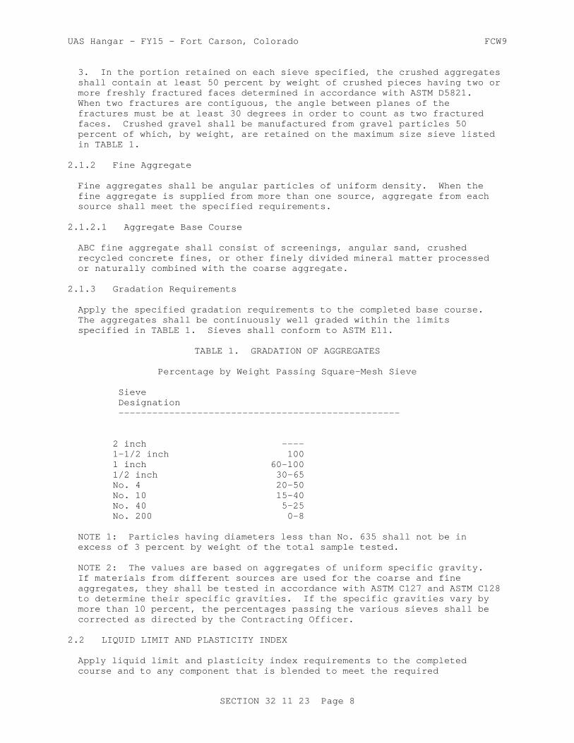
UAS Hangar - FY15 - Fort Carson, Colorado FCW9
3. In the portion retained on each sieve specified, the crushed aggregates shall contain at least 50 percent by weight of crushed pieces having two or more freshly fractured faces determined in accordance with ASTM D5821. When two fractures are contiguous, the angle between planes of the fractures must be at least 30 degrees in order to count as two fractured faces. Crushed gravel shall be manufactured from gravel particles 50 percent of which, by weight, are retained on the maximum size sieve listed in TABLE 1.
2.1.2 Fine Aggregate
Fine aggregates shall be angular particles of uniform density. When the fine aggregate is supplied from more than one source, aggregate from each source shall meet the specified requirements.
2.1.2.1 Aggregate Base Course
ABC fine aggregate shall consist of screenings, angular sand, crushed recycled concrete fines, or other finely divided mineral matter processed or naturally combined with the coarse aggregate.
2.1.3 Gradation Requirements
Apply the specified gradation requirements to the completed base course. The aggregates shall be continuously well graded within the limits specified in TABLE 1. Sieves shall conform to ASTM E11.
TABLE 1. GRADATION OF AGGREGATES
Percentage by Weight Passing Square-Mesh Sieve
Sieve Designation --------------------------------------------------
2 inch ---- 1-1/2 inch 100 1 inch 60-100 1/2 inch 30-65 No. 4 20-50 No. 10 15-40 No. 40 5-25 No. 200 0-8
NOTE 1: Particles having diameters less than No. 635 shall not be in excess of 3 percent by weight of the total sample tested.
NOTE 2: The values are based on aggregates of uniform specific gravity. If materials from different sources are used for the coarse and fine aggregates, they shall be tested in accordance with ASTM C127 and ASTM C128 to determine their specific gravities. If the specific gravities vary by more than 10 percent, the percentages passing the various sieves shall be corrected as directed by the Contracting Officer.
2.2 LIQUID LIMIT AND PLASTICITY INDEX
Apply liquid limit and plasticity index requirements to the completed course and to any component that is blended to meet the required
SECTION 32 11 23 Page 8

UAS Hangar - FY15 - Fort Carson, Colorado FCW9
gradation. The portion of any component or of the completed course passing the No. 40 sieve shall be either nonplastic or have a liquid limit not greater than 25 and a plasticity index not greater than 5.
PART 3 EXECUTION
3.1 GENERAL REQUIREMENTS
When the ABC is constructed in more than one layer, clean the previously constructed layer of loose and foreign matter by sweeping with power sweepers or power brooms, except that hand brooms may be used in areas where power cleaning is not practicable. Provide adequate drainage during the entire period of construction to prevent water from collecting or standing on the working area. Provide line and grade stakes as necessary for control. Grade stakes shall be in lines parallel to the centerline of the area under construction and suitably spaced for string lining.
3.2 STOCKPILING MATERIAL
Clear and level storage sites prior to stockpiling of material. Stockpile all materials, including approved material available from excavation and grading, in the manner and at the locations designated. Aggregates shall be stockpiled on the cleared and leveled areas designated by the Contracting Officer to prevent segregation. Materials obtained from different sources shall be stockpiled separately.
3.3 PREPARATION OF UNDERLYING COURSE
Prior to constructing the base course(s), the underlying course or subgrade shall be cleaned of all foreign substances. At the time of construction of the base course(s), the underlying course shall contain no frozen material. The surface of the underlying course or subgrade shall meet specified compaction and surface tolerances. The underlying course shall conform to Section 32 11 16 BASE COURSE FOR RIGID AND SUBBASES FOR FLEXIBLE PAVING. Ruts or soft yielding spots in the underlying courses, areas having inadequate compaction, and deviations of the surface from the requirements set forth herein shall be corrected by loosening and removing soft or unsatisfactory material and by adding approved material, reshaping to line and grade, and recompacting to specified density requirements. For cohesionless underlying courses containing sands or gravels, as defined in ASTM D2487, the surface shall be stabilized prior to placement of the base course(s). Stabilization shall be accomplished by mixing ABC into the underlying course and compacting by approved methods. The stabilized material shall be considered as part of the underlying course and shall meet all requirements of the underlying course. The finished underlying course shall not be disturbed by traffic or other operations and shall be maintained in a satisfactory condition until the base course is placed.
3.4 INSTALLATION
3.4.1 Mixing the Materials
Mix the coarse and fine aggregates in a stationary plant, or in a traveling plant or bucket loader on an approved paved working area. Make adjustments in mixing procedures or in equipment, as directed, to obtain true grades, to minimize segregation or degradation, to obtain the required water content, and to insure a satisfactory base course meeting all requirements of this specification.
SECTION 32 11 23 Page 9
UAS Hangar - FY15 - Fort Carson, Colorado FCW9
3.4.2 Placing
Place the mixed material on the prepared subgrade or subbase in layers of uniform thickness with an approved spreader. When a compacted layer 6 inches or less in thickness is required, place the material in a single layer. When a compacted layer in excess of 6 inches is required, place the material in layers of equal thickness. No layer shall be thicker than 6 inches or thinner than 3 inches when compacted. The layers shall be so placed that when compacted they will be true to the grades or levels required with the least possible surface disturbance. Where the base course is placed in more than one layer, the previously constructed layers shall be cleaned of loose and foreign matter by sweeping with power sweepers, power brooms, or hand brooms, as directed. Such adjustments in placing procedures or equipment shall be made as may be directed to obtain true grades, to minimize segregation and degradation, to adjust the water content, and to insure an acceptable base course.
3.4.3 Grade Control
The finished and completed base course shall conform to the lines, grades, and cross sections shown. Underlying material(s) shall be excavated and prepared at sufficient depth for the required base course thickness so that the finished base course and the subsequent surface course will meet the designated grades.
3.4.4 Edges of Base Course
The base course(s) shall be placed so that the completed section will be a minimum of 2 feet wider, on all sides, than the next layer that will be placed above it. Additionally, place approved fill material along the outer edges of the base course in sufficient quantities to compact to the thickness of the course being constructed, or to the thickness of each layer in a multiple layer course, allowing in each operation at least a 2 foot width of this material to be rolled and compacted simultaneously with rolling and compacting of each layer of base course. If this base course material is to be placed adjacent to another pavement section, then the layers for both of these sections shall be placed and compacted along this edge at the same time.
3.4.5 Compaction
Compact each layer of the base course, as specified, with approved compaction equipment. Maintain water content during the compaction procedure to within plus or minus 2 percent of the optimum water content determined from laboratory tests as specified in this Section. Begin rolling at the outside edge of the surface and proceed to the center, overlapping on successive trips at least one-half the width of the roller. Alternate trips of the roller shall be slightly different lengths. Speed of the roller shall be such that displacement of the aggregate does not occur. In all places not accessible to the rollers, the mixture shall be compacted with hand-operated power tampers. Continue compaction until each layer has a degree of compaction that is at least 100 percent of laboratory maximum density through the full depth of the layer. Make such adjustments in compacting or finishing procedures as may be directed to obtain true grades, to minimize segregation and degradation, to reduce or increase water content, and to ensure a satisfactory base course. Any materials that are found to be unsatisfactory shall be removed and replaced with satisfactory material or reworked, as directed, to meet the requirements of this specification.
SECTION 32 11 23 Page 10

UAS Hangar - FY15 - Fort Carson, Colorado FCW9
3.4.6 Thickness
Construct the compacted thickness of the base course as indicated. No individual layer shall be thicker than 6 inches nor be thinner than 3 inches in compacted thickness. The total compacted thickness of the base course(s) shall be within 1/2 inch of the thickness indicated. Where the measured thickness is more than 1/2 inch deficient, correct such areas by scarifying, adding new material of proper gradation, reblading, and recompacting as directed. Where the measured thickness is more than 1/2 inch thicker than indicated, the course shall be considered as conforming to the specified thickness requirements. Average job thickness shall be the average of all thickness measurements taken for the job, but shall be within 1/4 inch of the thickness indicated. The total thickness of the base course shall be measured at intervals in such a manner as to ensure one measurement for each 500 square yards of base course. Measurements shall be made in 3 inch diameter test holes penetrating the base course.
3.4.7 Finishing
The surface of the top layer of base course shall be finished after final compaction by cutting any overbuild to grade and rolling with a steel-wheeled roller. Thin layers of material shall not be added to the top layer of base course to meet grade. If the elevation of the top layer of base course is 1/2 inch or more below grade, then the top layer should be scarified to a depth of at least 3 inches and new material shall be blended in and compacted to bring to grade. Adjustments to rolling and finishing procedures shall be made as directed to minimize segregation and degradation, obtain grades, maintain moisture content, and insure an acceptable base course. Should the surface become rough, corrugated, uneven in texture, or traffic marked prior to completion, the unsatisfactory portion shall be scarified, reworked and recompacted or it shall be replaced as directed.
3.4.8 Smoothness
The surface of the top layer shall show no deviations in excess of 3/8 inch when tested with a 12 foot straightedge. Take measurements in successive positions parallel to the centerline of the area to be paved. Measurements shall also be taken perpendicular to the centerline at 50 foot intervals. Deviations exceeding this amount shall be corrected by removing material and replacing with new material, or by reworking existing material and compacting it to meet these specifications.
3.5 TRAFFIC
Do not allow traffic on the completed base course.
3.6 MAINTENANCE
Maintain the base course in a satisfactory condition until the full pavement section is completed and accepted. Maintenance shall include immediate repairs to any defects and shall be repeated as often as necessary to keep the area intact. Any base course that is not paved over prior to the onset of winter, shall be retested to verify that it still complies with the requirements of this specification. Any area of base course that is damaged shall be reworked or replaced as necessary to comply with this specification.
SECTION 32 11 23 Page 11

UAS Hangar - FY15 - Fort Carson, Colorado FCW9
3.7 DISPOSAL OF UNSATISFACTORY MATERIALS
Any unsuitable materials that must be removed shall be disposed of outside the limits of Government-controlled land. No additional payments will be made for materials that must be replaced.
-- End of Section --
SECTION 32 11 23 Page 12

UAS Hangar - FY15 - Fort Carson, Colorado FCW9
SECTION TABLE OF CONTENTS
DIVISION 32 - EXTERIOR IMPROVEMENTS
SECTION 32 12 10
BITUMINOUS TACK AND PRIME COATS
08/08
PART 1 GENERAL
1.1 REFERENCES 1.2 SYSTEM DESCRIPTION 1.2.1 General Requirements 1.2.2 Bituminous Distributor 1.2.3 Heating Equipment for Storage Tanks 1.2.4 Power Brooms and Power Blowers 1.3 SUBMITTALS 1.4 DELIVERY, STORAGE, AND HANDLING 1.5 ENVIRONMENTAL REQUIREMENTS
PART 2 PRODUCTS
2.1 PRIME COAT 2.1.1 Emulsified Asphalt 2.2 TACK COAT 2.2.1 Emulsified Asphalt
PART 3 EXECUTION
3.1 PREPARATION OF SURFACE 3.2 APPLICATION RATE 3.2.1 Tack Coat 3.2.2 Prime Coat 3.3 APPLICATION TEMPERATURE 3.3.1 Viscosity Relationship 3.3.2 Temperature Ranges 3.4 APPLICATION 3.4.1 General 3.4.2 Prime Coat 3.4.3 Tack Coat 3.5 CURING PERIOD 3.6 FIELD QUALITY CONTROL 3.7 SAMPLING AND TESTING 3.7.1 Sampling 3.7.2 Calibration Test 3.7.3 Trial Applications 3.7.3.1 Tack Coat Trial Application Rate 3.7.3.2 Prime Coat Trial Application Rate 3.7.4 Sampling and Testing During Construction 3.8 TRAFFIC CONTROLS
-- End of Section Table of Contents --
SECTION 32 12 10 Page 1

UAS Hangar - FY15 - Fort Carson, Colorado FCW9
SECTION 32 12 10
BITUMINOUS TACK AND PRIME COATS08/08
PART 1 GENERAL
1.1 REFERENCES
The publications listed below form a part of this specification to the extent referenced. The publications are referred to within the text by the basic designation only.
AMERICAN ASSOCIATION OF STATE HIGHWAY AND TRANSPORTATION OFFICIALS (AASHTO)
AASHTO M 226 (1980; R 2008) Standard Specification for Viscosity-Graded Asphalt Cement
AASHTO M 81 (1992; R 2008) Standard Specification for Cutback Asphalt (Rapid-Curing Type)
AASHTO M 82 (1975; R 2008) Standard Specification for Cutback Asphalt (Medium-Curing Type)
AASHTO T 102 (2009) Standard Method of Test for Spot Test of Asphaltic Materials
AASHTO T 40 (2002; R 2006) Sampling Bituminous Materials
ASTM INTERNATIONAL (ASTM)
ASTM D1250 (2008) Standard Guide for Use of the Petroleum Measurement Tables
ASTM D140/D140M (2009) Standard Practice for Sampling Bituminous Materials
ASTM D2026/D2026M (1997; R 2010e1) Cutback Asphalt (Slow-Curing Type)
ASTM D2027 (2010) Cutback Asphalt (Medium-Curing Type)
ASTM D2028/D2028M (2010) Cutback Asphalt (Rapid-Curing Type)
ASTM D2397 (2005) Standard Specification for Cationic Emulsified Asphalt
ASTM D2995 (1999; R 2009) Determining Application Rate of Bituminous Distributors
ASTM D3381/D3381M (2009a) Viscosity-Graded Asphalt Cement for Use in Pavement Construction
ASTM D946/D946M (2009a) Penetration-Graded Asphalt Cement
SECTION 32 12 10 Page 2

UAS Hangar - FY15 - Fort Carson, Colorado FCW9
for Use in Pavement Construction
ASTM D977 (2012) Emulsified Asphalt
U.S. GREEN BUILDING COUNCIL (USGBC)
LEED NC (2009) Leadership in Energy and Environmental Design(tm) New Construction Rating System
1.2 SYSTEM DESCRIPTION
1.2.1 General Requirements
Plant, equipment, machines and tools used in the work are subject to approval and shall be maintained in a satisfactory working condition at all times. Calibrated equipment such as asphalt distributors, scales, batching equipment, spreaders and similar equipment, should have been recalibrated by a calibration laboratory within 12 months prior to commencing work.
1.2.2 Bituminous Distributor
Provide a distributor with pneumatic tires of such size and number that the load produced on the base surface does not exceed 650 psi of tire width to prevent rutting, shoving or otherwise damaging the base surface or other layers in the pavement structure. Design and equip the distributor to spray the bituminous material in a uniform coverage at the specified temperature, at readily determined and controlled rates from 0.05 to 2.0 gallons per square yard, with a pressure range of 25 to 75 psi and with an allowable variation from the specified rate of not more than plus or minus 5 percent, and at variable widths. Include with the distributor equipment a separate power unit for the bitumen pump, full-circulation spray bars, tachometer, pressure gauges, volume-measuring devices, adequate heaters for heating of materials to the proper application temperature, a thermometer for reading the temperature of tank contents, and a hand hose attachment suitable for applying bituminous material manually to areas inaccessible to the distributor. Equip the distributor to circulate and agitate the bituminous material during the heating process.
1.2.3 Heating Equipment for Storage Tanks
The equipment for heating the bituminous material shall be steam, electric, or hot oil heaters. Provide steam heaters consisting of steam coils and equipment for producing steam, so designed that the steam cannot get into the material. Fix an armored thermometer to the tank with a temperature range from 40 to 400 degrees F so that the temperature of the bituminous material may be determined at all times.
1.2.4 Power Brooms and Power Blowers
Use power brooms and power blowers suitable for cleaning the surfaces to which the bituminous coat is to be applied.
1.3 SUBMITTALS
Government approval is required for submittals with a "G" designation; submittals not having a "G" designation are for information only. When used, a designation following the "G" designation identifies the office that will review the submittal for the Government. Submit the following in
SECTION 32 12 10 Page 3

UAS Hangar - FY15 - Fort Carson, Colorado FCW9
accordance with Section 01 33 00 SUBMITTAL PROCEDURES:
SD-03 Product Data
Local/Regional Materials
SD-06 Test Reports
Sampling and Testing
1.4 DELIVERY, STORAGE, AND HANDLING
Inspect the materials delivered to the site for contamination and damage. Unload and store the materials with a minimum of handling.
1.5 ENVIRONMENTAL REQUIREMENTS
Apply bituminous coat only when the surface to receive the bituminous coat is dry. Apply bituminous coat only when the atmospheric temperature in the shade is 50 degrees F or above and when the temperature has not been below 35 degrees F for the 12 hours prior to application, unless otherwise directed.
PART 2 PRODUCTS
2.1 PRIME COAT
2.1.1 Emulsified Asphalt
Provide emulsified asphalt conforming to ASTM D977, Type SS-1 or SS1h; or ASTM D2397, Type CSS-1 or CSS-1h.
2.2 TACK COAT
2.2.1 Emulsified Asphalt
Provide emulsified asphalt conforming to ASTM D977, Type SS-1 or SS1h; or ASTM D2397, Type CSS-1 or CSS-1h. Dilute the emulsified asphalt with equal parts of water. The base asphalt used to manufacture the emulsion shall show a negative spot when tested in accordance with AASHTO T 102 using standard naphtha.
PART 3 EXECUTION
3.1 PREPARATION OF SURFACE
Immediately before applying the bituminous coat, remove all loose material, dirt, clay, or other objectionable material from the surface to be treated by means of a power broom or blower supplemented with hand brooms. The surface shall be dry and clean at the time of treatment.
3.2 APPLICATION RATE
The exact quantities within the range specified, which may be varied to suit field conditions, will be determined by the Contracting Officer.
SECTION 32 12 10 Page 4

UAS Hangar - FY15 - Fort Carson, Colorado FCW9
3.2.1 Tack Coat
Apply bituminous material for the tack coat in quantities of not less than 0.05 gallon nor more than 0.15 gallon per square yard of pavement surface.
3.2.2 Prime Coat
Apply bituminous material for the prime coat in quantities of not less than 0.18 gallon nor more than 0.35 gallon per square yard of pavement surface.
3.3 APPLICATION TEMPERATURE
3.3.1 Viscosity Relationship
Asphalt application temperature shall provide an application viscosity between 10 and 60 seconds, Saybolt Furol, or between 20 and 120 centistokes, kinematic. Furnish the temperature viscosity relation to the Contracting Officer.
3.3.2 Temperature Ranges
The viscosity requirements determine the application temperature to be used. The following is a normal range of application temperatures:
Emulsions ------------- SS-1 70-160 degrees F SS-1h 70-160 degrees F CSS-1 70-160 degrees F CSS-1h 70-160 degrees F
These temperature ranges exceed the flash point of the material and care should be taken in their heating.
3.4 APPLICATION
3.4.1 General
Following preparation and subsequent inspection of the surface, apply the bituminous prime or tack coat with the Bituminous Distributor at the specified rate with uniform distribution over the surface to be treated. Properly treat all areas and spots missed by the distributor with the hand spray. Until the succeeding layer of pavement is placed, maintain the surface by protecting the surface against damage and by repairing deficient areas at no additional cost to the Government. If required, spread clean dry sand to effectively blot up any excess bituminous material. No smoking, fires, or flames other than those from the heaters that are a part of the equipment are permitted within 25 feet of heating, distributing, and transferring operations of bituminous material other than bituminous emulsions. Prevent all traffic, except for paving equipment used in constructing the surfacing, from using the underlying material, whether primed or not, until the surfacing is completed. The bituminous coat shall conform to all requirements as described herein.
SECTION 32 12 10 Page 5

UAS Hangar - FY15 - Fort Carson, Colorado FCW9
3.4.2 Prime Coat
Apply a prime coat at locations shown on the Drawings. Apply prime coat as soon as possible after consolidation of the underlying material. Apply the bituminous material uniformly over the surface to be treated at a pressure range of 25 to 75 psi; the rate shall be as specified above in paragraph APPLICATION RATE. To obtain uniform application of the prime coat on the surface treated at the junction of previous and subsequent applications, spread building paper on the surface for a sufficient distance back from the ends of each application to start and stop the prime coat on the paper and to ensure that all sprayers will operate at full force on the surface to be treated. Immediately after application remove and destroy the building paper.
3.4.3 Tack Coat
Apply tack coat at the locations shown on the drawings. Apply the tack coat when the surface to be treated is dry. Immediately following the preparation of the surface for treatment, apply the bituminous material by means of the bituminous distributor, within the limits of temperature specified herein and at a rate as specified above in paragraph APPLICATION RATE. Apply the bituminous material so that uniform distribution is obtained over the entire surface to be treated. Treat lightly coated areas and spots missed by the distributor with the bituminous material. Following the application of bituminous material, allow the surface to cure without being disturbed for period of time necessary to permit setting of the tack coat. Apply the bituminous tack coat only as far in advance of the placing of the overlying layer as required for that day's operation. Maintain and protect the treated surface from damage until the succeeding course of pavement is placed.
3.5 CURING PERIOD
Following application of the bituminous material and prior to application of the succeeding layer of pavement, allow the bituminous coat to cure and to obtain evaporation of any volatiles or moisture. Maintain the coated surface until the succeeding layer of pavement is placed, by protecting the surface against damage and by repairing and recoating deficient areas. Allow the prime coat to cure without being disturbed for a period of at least 48 hours or longer, as may be necessary to attain penetration into the treated course. Furnish and spread enough sand to effectively blot up and cure excess bituminous material.
3.6 FIELD QUALITY CONTROL
Samples of the bituminous material shall be tested for compliance with the applicable specified requirements. A sample shall be obtained and tested by the Contractor.
3.7 SAMPLING AND TESTING
Submit copies of all test results for emulsified asphalt, and bituminous materials, within 24 hours of completion of tests. Furnish certified copies of the manufacturer's test reports indicating temperature viscosity relationship for cutback asphalt, compliance with applicable specified requirements, not less than 30 days before the material is required in the work. Perform sampling and testing by an approved commercial testing laboratory or by facilities furnished by the Contractor. No work requiring testing will be permitted until the facilities have been inspected and
SECTION 32 12 10 Page 6

UAS Hangar - FY15 - Fort Carson, Colorado FCW9
approved.
3.7.1 Sampling
The samples of bituminous material, unless otherwise specified, shall be in accordance with ASTM D140/D140M or AASHTO T 40. Sources from which bituminous materials are to be obtained shall be selected and notification furnished the Contracting Officer within 15 days after the award of the contract.
3.7.2 Calibration Test
Furnish all equipment, materials, and labor necessary to calibrate the bituminous distributor. Calibration shall be made with the approved job material and prior to applying the bituminous coat material to the prepared surface. Calibrate the bituminous distributor in accordance with ASTM D2995.
3.7.3 Trial Applications
Before providing the complete bituminous coat, apply three lengths of at least 100 feet for the full width of the distributor bar to evaluate the amount of bituminous material that can be satisfactorily applied.
3.7.3.1 Tack Coat Trial Application Rate
Unless otherwise authorized, apply the trial application rate of bituminous tack coat materials in the amount of 0.05 gallons per square yard. Other trial applications shall be made using various amounts of material as may be deemed necessary.
3.7.3.2 Prime Coat Trial Application Rate
Unless otherwise authorized, apply the trial application rate of bituminous materials in the amount of 0.25 gallon per square yard. Other trial applications shall be made using various amounts of material as may be deemed necessary.
3.7.4 Sampling and Testing During Construction
Perform quality control sampling and testing as required in paragraph FIELD QUALITY CONTROL.
3.8 TRAFFIC CONTROLS
Keep traffic off surfaces freshly treated with bituminous material. Provide sufficient warning signs and barricades so that traffic will not travel over freshly treated surfaces.
-- End of Section --
SECTION 32 12 10 Page 7

This page was intentionally left blank for duplex printing.

UAS Hangar - FY15 - Fort Carson, Colorado FCW9
SECTION TABLE OF CONTENTS
DIVISION 32 - EXTERIOR IMPROVEMENTS
SECTION 32 12 15.13
HOT-MIX ASPHALT AIRFIELD PAVING
11/12
PART 1 GENERAL
1.1 FULL PAYMENT 1.1.1 Method of Measurement 1.1.2 Basis of Payment 1.2 PERCENT PAYMENT 1.2.1 Mat and Joint Densities 1.2.2 Pay Factor Based on In-place Density 1.2.3 Payment Adjustment for Smoothness 1.2.4 Laboratory Air Voids and Theoretical Maximum Density 1.2.5 Mean Absolute Deviation 1.2.6 Pay Adjustment Based on Grade 1.3 REFERENCES 1.4 SYSTEM DESCRIPTION 1.4.1 Asphalt Mixing Plant 1.4.2 Hauling Equipment 1.4.3 Material Transfer Vehicle (MTV) 1.4.4 Asphalt Pavers 1.4.4.1 Receiving Hopper 1.4.4.2 Automatic Grade Controls 1.4.5 Rollers 1.5 SUBMITTALS 1.6 QUALITY ASSURANCE 1.6.1 Sublot Sampling 1.6.2 Additional Sampling and Testing 1.6.3 In-place Density 1.6.4 Surface Smoothness 1.6.4.1 Smoothness Requirements 1.6.4.2 Testing Method 1.7 ENVIRONMENTAL REQUIREMENTS
PART 2 PRODUCTS
2.1 AGGREGATES 2.1.1 Coarse Aggregate 2.1.2 Fine Aggregate 2.1.3 Mineral Filler 2.1.4 Aggregate Gradation 2.2 ASPHALT CEMENT BINDER 2.3 MIX DESIGN 2.3.1 JMF Requirements 2.3.2 Adjustments to JMF
PART 3 EXECUTION
3.1 CONTRACTOR QUALITY CONTROL
SECTION 32 12 15.13 Page 1

UAS Hangar - FY15 - Fort Carson, Colorado FCW9
3.1.1 General Quality Control Requirements 3.1.2 Testing Laboratory 3.1.3 Quality Control Testing 3.1.3.1 Asphalt Content 3.1.3.2 Aggregate Properties 3.1.3.3 Temperatures 3.1.3.4 Aggregate Moisture 3.1.3.5 Moisture Content of Mixture 3.1.3.6 Laboratory Air Voids, VMA 3.1.3.7 In-Place Density 3.1.3.8 Grade and Smoothness 3.1.3.9 Additional Testing 3.1.3.10 QC Monitoring 3.1.4 Sampling 3.1.5 Control Charts 3.2 PREPARATION OF ASPHALT BINDER MATERIAL 3.3 PREPARATION OF MINERAL AGGREGATE 3.4 PREPARATION OF HOT-MIX ASPHALT MIXTURE 3.5 PREPARATION OF THE UNDERLYING SURFACE 3.6 TEST SECTION 3.6.1 Sampling and Testing for Test Section 3.6.2 Additional Test Sections 3.7 TESTING LABORATORY 3.8 TRANSPORTING AND PLACING 3.8.1 Transporting 3.8.2 Placing 3.9 COMPACTION OF MIXTURE 3.9.1 General 3.9.2 Segregation 3.10 JOINTS 3.10.1 Transverse Joints 3.10.2 Longitudinal Joints 3.10.3 HMA-Portland Cement Concrete Joints
-- End of Section Table of Contents --
SECTION 32 12 15.13 Page 2

UAS Hangar - FY15 - Fort Carson, Colorado FCW9
SECTION 32 12 15.13
HOT-MIX ASPHALT AIRFIELD PAVING11/12
PART 1 GENERAL
1.1 FULL PAYMENT
1.1.1 Method of Measurement
Measurement of the quantity of hot-mix asphalt, per ton placed and accepted, shall be made for the purposes of assessing the pay factors stipulated below.
1.1.2 Basis of Payment
The measured quantity of hot-mixed asphalt will be paid for and included in the lump-sum contract price. If less than 100 percent payment is due based on the pay factors stipulated in paragraph QUALITY ASSURANCE, a unit price of $100 per ton will be used for purposes of calculating the payment reduction.
1.2 PERCENT PAYMENT
When a lot of material fails to meet the specification requirements for 100 percent pay as outlined in the following paragraphs, that lot shall be removed and replaced, or accepted at a reduced price which will be computed by multiplying the unit price by the lot's pay factor. The lot pay factor is determined by taking the lowest computed pay factor based on either laboratory air voids, in-place density, grade or smoothness (each discussed below). Pay factors based on different criteria (i.e., laboratory air voids and in-place density) of the same lot will not be multiplied together to get a lower lot pay factor. At the end of the project, an average of all lot pay factors will be calculated. If this average lot pay factor exceeds 95.0 percent and no individual lot has a pay factor less than 75.1 percent, then the percent payment for the entire project will be 100 percent of the unit bid price. If the average lot pay factor is less than 95.0 percent, then each lot will be paid for at the unit price multiplied by the lot's pay factor. For any lots which are less than 2000 short tons, a weighted lot pay factor will be used to calculate the average lot pay factor.
1.2.1 Mat and Joint Densities
The average in-place mat and joint densities are expressed as a percentage of the average theoretical maximum density (TMD) for the lot. The average TMD for each lot will be determined as the average TMD of the two random samples per lot. The average in-place mat density and joint density for a lot are determined and compared with Table 1 to calculate a single pay factor per lot based on in-place density, as described below. First, a pay factor for both mat density and joint density are determined from Table 1. The area associated with the joint is then determined and will be considered to be 10 feet wide times the length of completed longitudinal construction joint in the lot. This area will not exceed the total lot size. The length of joint to be considered will be that length where a new
SECTION 32 12 15.13 Page 3
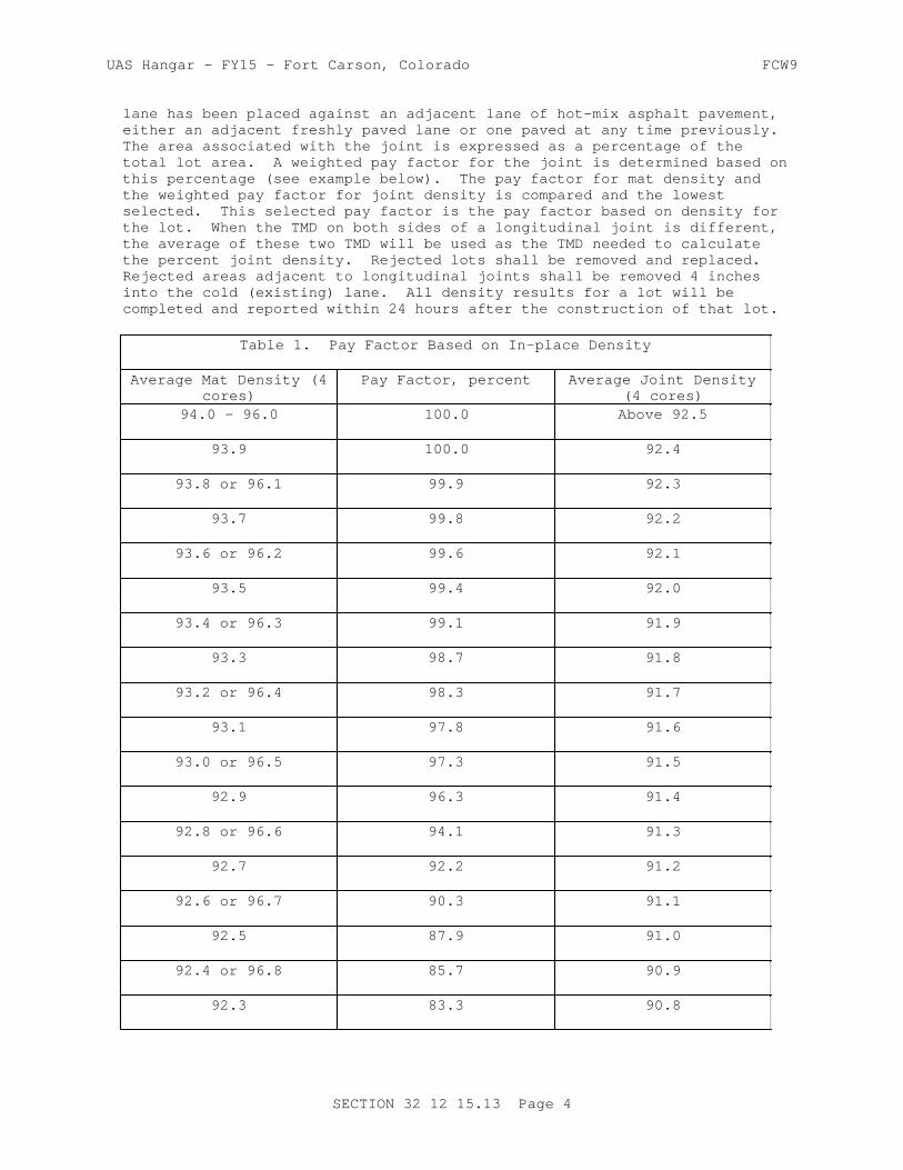
UAS Hangar - FY15 - Fort Carson, Colorado FCW9
lane has been placed against an adjacent lane of hot-mix asphalt pavement, either an adjacent freshly paved lane or one paved at any time previously. The area associated with the joint is expressed as a percentage of the total lot area. A weighted pay factor for the joint is determined based on this percentage (see example below). The pay factor for mat density and the weighted pay factor for joint density is compared and the lowest selected. This selected pay factor is the pay factor based on density for the lot. When the TMD on both sides of a longitudinal joint is different, the average of these two TMD will be used as the TMD needed to calculate the percent joint density. Rejected lots shall be removed and replaced. Rejected areas adjacent to longitudinal joints shall be removed 4 inches into the cold (existing) lane. All density results for a lot will be completed and reported within 24 hours after the construction of that lot.
Table 1. Pay Factor Based on In-place Density
Average Mat Density (4cores)
Pay Factor, percent Average Joint Density(4 cores)
94.0 - 96.0 100.0 Above 92.5
93.9 100.0 92.4
93.8 or 96.1 99.9 92.3
93.7 99.8 92.2
93.6 or 96.2 99.6 92.1
93.5 99.4 92.0
93.4 or 96.3 99.1 91.9
93.3 98.7 91.8
93.2 or 96.4 98.3 91.7
93.1 97.8 91.6
93.0 or 96.5 97.3 91.5
92.9 96.3 91.4
92.8 or 96.6 94.1 91.3
92.7 92.2 91.2
92.6 or 96.7 90.3 91.1
92.5 87.9 91.0
92.4 or 96.8 85.7 90.9
92.3 83.3 90.8
SECTION 32 12 15.13 Page 4

UAS Hangar - FY15 - Fort Carson, Colorado FCW9
Table 1. Pay Factor Based on In-place Density
Average Mat Density (4cores)
Pay Factor, percent Average Joint Density(4 cores)
92.2 or 96.9 80.6 90.7
92.1 78.0 90.6
92.0 or 97.0 75.0 90.5
below 92.0, above 97.0 0.0 (reject) below 90.5
1.2.2 Pay Factor Based on In-place Density
An example of the computation of a pay factor (in I-P units only) based on in-place density, is as follows: Assume the following test results for field density made on the lot: (1) Average mat density = 93.2 percent (of lab TMD). (2) Average joint density = 91.5 percent (of lab TMD). (3) Total area of lot = 30,000 square feet. (4) Length of completed longitudinal construction joint = 2000 feet.
a. Step 1: Determine pay factor based on mat density and on joint density, using Table 1:
Mat density of 93.2 percent = 98.3 pay factor.
Joint density of 91.5 percent = 97.3 pay factor.
b. Step 2: Determine ratio of joint area (length of longitudinal joint x 10 ft) to mat area (total paved area in the lot): Multiply the length of completed longitudinal construction joint by the specified 10 ft. width and divide by the mat area (total paved area in the lot).
(2000 ft. x 10 ft.)/30000 sq.ft. = 0.6667 ratio of joint area to mat area (ratio).
c. Step 3: Weighted pay factor (wpf) for joint is determined as indicated below:
wpf = joint pay factor + (100 - joint pay factor) (1 - ratio) wpf = 97.3 + (100-97.3) (1-.6667) = 98.2 percent
d. Step 4: Compare weighted pay factor for joint density to pay factor for mat density and select the smaller:
Pay factor for mat density: 98.3 percent. Weighted pay factor for joint density: 98.2 percent
Select the smaller of the two values as pay factor based on density: 98.2 percent
1.2.3 Payment Adjustment for Smoothness
a. Straightedge Testing. Location and deviation from straightedge for all measurements shall be recorded. When between 5.0 and 10.0 percent of all measurements made within a lot exceed the tolerance specified in paragraph Smoothness Requirements below, after any reduction of high
SECTION 32 12 15.13 Page 5

UAS Hangar - FY15 - Fort Carson, Colorado FCW9
spots or removal and replacement, the computed pay factor for that lot based on surface smoothness, will be 95 percent. When more than 10.0 percent of all measurements exceed the tolerance, the computed pay factor will be 90 percent. When between 15.0 and 20.0 percent of all measurements exceed the tolerance, the computed pay factor will be 75 percent. When 20.0 percent or more of the measurements exceed the tolerance, the lot shall be removed and replaced at no additional cost to the Government. Regardless of the above, any small individual area with surface deviation which exceeds the tolerance given above by more than 50 percent, shall be corrected by diamond grinding to meet the specification requirements above or shall be removed and replaced at no additional cost to the Government.
b. Profilograph Testing. Location and data from all profilograph measurements shall be recorded. When the Profile Index of a lot exceeds the tolerance specified in paragraph Smoothness Requirements by 1.0 inch/mile, but less than 2.0 inches/mile, after any reduction of high spots or removal and replacement, the computed pay factor for that lot based on surface smoothness will be 95 percent. When the Profile Index exceeds the tolerance by 2.0 inches/mile, but less than 3.0 inches/mile, the computed pay factor will be 90 percent. When the Profile Index exceeds the tolerance by 3.0 inches/mile, but less than 4.0 inches/mile, the computed pay factor will be 75 percent. When the Profile Index exceeds the tolerance by 4.0 inches/mile or more, the lot shall be removed and replaced at no additional cost to the Government. Regardless of the above, any small individual area with surface deviation which exceeds the tolerance given above by more than 5.0 inches/mile or more, shall be corrected by grinding to meet the specification requirements above or shall be removed and replaced at no additional cost to the Government.
1.2.4 Laboratory Air Voids and Theoretical Maximum Density
Laboratory air voids will be calculated in accordance with ASTM D3203/D3203M by determining the Marshall density of each lab compacted specimen using the laboratory-prepared, thoroughly dry method in ASTM D2726 and determining the theoretical maximum density (TMD) of two of the sublots using ASTM D2041/D2041M. Laboratory air void calculations for each lot will use the average theoretical maximum density values obtained for the lot. The mean absolute deviation of the four laboratory air void contents (one from each sublot) from the JMF air void content will be evaluated and a pay factor determined from Table 2. All laboratory air void tests will be completed and reported within 24 hours after completion of construction of each lot. The TMD is also used for computation of compaction, as required in paragraph: Mat and Joint Densities above.
1.2.5 Mean Absolute Deviation
An example of the computation of mean absolute deviation for laboratory air voids is as follows: Assume that the laboratory air voids are determined from 4 random samples of a lot (where 3 specimens were compacted from each sample). The average laboratory air voids for each sublot sample are determined to be 3.5, 3.0, 4.0, and 3.7. Assume that the target air voids from the JMF is 4.0. The mean absolute deviation is then:
Mean Absolute Deviation = (|3.5 - 4.0| + |3.0 - 4.0| + |4.0 - 4.0| + |3.7 - 4.0|)/4
= (0.5 + 1.0 + 0.0 + 0.3)/4 = (1.8)/4 = 0.45
SECTION 32 12 15.13 Page 6

UAS Hangar - FY15 - Fort Carson, Colorado FCW9
The mean absolute deviation for laboratory air voids is determined to be 0.45. It can be seen from Table 2 that the lot's pay factor based on laboratory air voids, is 100 percent.
Table 2. Pay Factor Based on Laboratory Air Voids
Mean Absolute Deviation of Lab Air Voids from JMF Pay Factor, Percent
O.60 or less 100
0.61 - 0.80 98
0.81 - 1.00 95
1.01 - 1.20 90
Above 1.20 reject (0)
1.2.6 Pay Adjustment Based on Grade
Within 5 working days after completion of a particular lot incorporating the final wearing course, test the final wearing surface of the pavement for conformance with specified plan grade requirements. All testing shall be performed in the presence of the Contracting Officer. The final wearing surface of pavement shall conform to the elevations and cross sections shown and shall vary not more than 0.03 foot for runways or 0.05 foot for taxiways and aprons from the plan grade established and approved at site of work. Finished surfaces at juncture with other pavements shall coincide with finished surfaces of abutting pavements. Deviation from the plan elevation will not be permitted in areas of pavements where closer conformance with planned elevation is required for the proper functioning of drainage and other appurtenant structures involved. The grade will be determined by running lines of levels at intervals of 25 feet, or less, longitudinally and transversely, to determine the elevation of the completed pavement surface. Detailed notes of the results of the testing shall be kept and a copy furnished to the Government immediately after each day's testing. When more than 5 percent of all measurements made within a lot are outside the 0.03 or 0.05 foot tolerance, the pay factor based on grade for that lot will be 95 percent. In areas where the grade exceeds the tolerance by more than 50 percent, remove the surface lift full depth; and replace the lift with hot-mix asphalt to meet specification requirements, at no additional cost to the Government. Diamond grinding may be used to remove high spots to meet grade requirements. Skin patching for correcting low areas or planing or milling for correcting high areas will not be permitted.
1.3 REFERENCES
The publications listed below form a part of this specification to the extent referenced. The publications are referred to within the text by the basic designation only.
AMERICAN ASSOCIATION OF STATE HIGHWAY AND TRANSPORTATION OFFICIALS (AASHTO)
AASHTO M 156 (1997: R 2009) Standard Specification for
SECTION 32 12 15.13 Page 7

UAS Hangar - FY15 - Fort Carson, Colorado FCW9
Requirements for Mixing Plants for Hot-Mixed, Hot-Laid Bituminous Paving Mixtures
AASHTO M 320 (2010) Standard Specification for Performance-Graded Asphalt Binder
AASHTO T 308 (2010) Standard Method of Test for Determining the Asphalt Binder Content of Hot Mix Asphalt (HMA) by the Ignition Method
AASHTO T 329 (2008) Standard Test Method for Moisture Content of Hot Mix Asphalt (HMA) by Oven Method
ASPHALT INSTITUTE (AI)
AI MS-02 (6th Edition: R 1997) Mix Design Methods for Asphalt
ASTM INTERNATIONAL (ASTM)
ASTM C117 (2013) Standard Test Method for Materials Finer than 75-um (No. 200) Sieve in Mineral Aggregates by Washing
ASTM C1252 (2006) Standard Test Methods for Uncompacted Void Content of Fine Aggregate (as Influenced by Particle Shape, Surface Texture, and Grading)
ASTM C127 (2012) Standard Test Method for Density, Relative Density (Specific Gravity), and Absorption of Coarse Aggregate
ASTM C128 (2012) Standard Test Method for Density, Relative Density (Specific Gravity), and Absorption of Fine Aggregate
ASTM C131 (2006) Standard Test Method for Resistance to Degradation of Small-Size Coarse Aggregate by Abrasion and Impact in the Los Angeles Machine
ASTM C136 (2006) Standard Test Method for Sieve Analysis of Fine and Coarse Aggregates
ASTM C142/C142M (2010) Standard Test Method for Clay Lumps and Friable Particles in Aggregates
ASTM C29/C29M (2009) Standard Test Method for Bulk Density ("Unit Weight") and Voids in Aggregate
ASTM C566 (1997; R 2004) Standard Test Method for Total Evaporable Moisture Content of Aggregate by Drying
SECTION 32 12 15.13 Page 8

UAS Hangar - FY15 - Fort Carson, Colorado FCW9
ASTM C88 (2013) Standard Test Method for Soundness of Aggregates by Use of Sodium Sulfate or Magnesium Sulfate
ASTM D140/D140M (2009) Standard Practice for Sampling Bituminous Materials
ASTM D1461 (20116) Moisture or Volatile Distillates in Bituminous Paving Mixtures
ASTM D2041/D2041M (2011) Theoretical Maximum Specific Gravity and Density of Bituminous Paving Mixtures
ASTM D2172/D2172M (2011) Quantitative Extraction of Bitumen from Bituminous Paving Mixtures
ASTM D2419 (2009) Sand Equivalent Value of Soils and Fine Aggregate
ASTM D242/D242M (2009) Mineral Filler for Bituminous Paving Mixtures
ASTM D2489/D2489M (2008) Estimating Degree of Particle Coating of Bituminous-Aggregate Mixtures
ASTM D2726 (2011) Bulk Specific Gravity and Density of Non-Absorptive Compacted Bituminous Mixtures
ASTM D3203/D3203M (2011) Percent Air Voids in Compacted Dense and Open Bituminous Paving Mixtures
ASTM D3381/D3381M (2009a) Viscosity-Graded Asphalt Cement for Use in Pavement Construction
ASTM D3665 (2012) Random Sampling of Construction Materials
ASTM D3666 (2011) Standard Specification for Minimum Requirements for Agencies Testing and Inspecting Road and Paving Materials
ASTM D4125/D4125M (2010) Asphalt Content of Bituminous Mixtures by the Nuclear Method
ASTM D4791 (2010) Flat Particles, Elongated Particles, or Flat and Elongated Particles in Coarse Aggregate
ASTM D4867/D4867M (2009) Effect of Moisture on Asphalt Concrete Paving Mixtures
ASTM D5444 (2008) Mechanical Size Analysis of Extracted Aggregate
ASTM D6307 (2010) Asphalt Content of Hot Mix Asphalt by Ignition Method
SECTION 32 12 15.13 Page 9

UAS Hangar - FY15 - Fort Carson, Colorado FCW9
ASTM D6925 (2009) Standard Test Method for Preparation and Determination of the Relative Density of Hot Mix Asphalt (HMA) Specimens by Means of the Superpave Gyratory Compactor
ASTM D6926 (2010) Standard Practice for Preparation of Bituminous Specimens Using Marshall Apparatus
ASTM D6927 (2006) Standard Test Method for Marshall Stability and Flow of Bituminous Mixtures
ASTM D946/D946M (2009a) Penetration-Graded Asphalt Cement for Use in Pavement Construction
ASTM D979/D979M (2012) Sampling Bituminous Paving Mixtures
ASTM E1274 (2003; R 2008) Standard Test Method for Measuring Pavement Roughness Using a Profilograph
U.S. ARMY CORPS OF ENGINEERS (USACE)
COE CRD-C 171 (1995) Standard Test Method for Determining Percentage of Crushed Particles in Aggregate
1.4 SYSTEM DESCRIPTION
Perform the work consisting of pavement courses composed of mineral aggregate and asphalt material heated and mixed in a central mixing plant and placed on a prepared course. Hot-mix asphalt (HMA) designed and constructed in accordance with this section shall conform to the lines, grades, thicknesses, and typical cross sections shown on the drawings. Construct each course to the depth, section, or elevation required by the drawings and rolled, finished, and approved before the placement of the next course. Submit proposed Placement Plan, indicating lane widths, longitudinal joints, and transverse joints for each course or lift.
1.4.1 Asphalt Mixing Plant
Plants used for the preparation of hot-mix asphalt shall conform to the requirements of AASHTO M 156 with the following changes:
a. Truck Scales. Weigh the asphalt mixture on approved scales furnished by the Contractor, or on certified public scales at the Contractor's expense. Scales shall be inspected and sealed at least annually by an approved calibration laboratory.
b. Testing Facilities. Provide laboratory facilities at the plant for the use of the Government's acceptance testing and the Contractor's quality control testing.
c. Inspection of Plant. The Contracting Officer shall have access at all times, to all areas of the plant for checking adequacy of equipment; inspecting operation of the plant; verifying weights, proportions, and material properties; checking the temperatures maintained in the preparation of the mixtures and for taking samples. Provide assistance
SECTION 32 12 15.13 Page 10
UAS Hangar - FY15 - Fort Carson, Colorado FCW9
as requested, for the Government to procure any desired samples.
d. Storage Bins. The asphalt mixture may be stored in non-insulated storage bins for a period of time not exceeding 3 hours. The asphalt mixture may be stored in insulated storage bins for a period of time not exceeding 8 hours. The mix drawn from bins shall meet the same requirements as mix loaded directly into trucks.
1.4.2 Hauling Equipment
Trucks used for hauling hot-mix asphalt shall have tight, clean, and smooth metal beds. To prevent the mixture from adhering to them, the truck beds shall be lightly coated with a minimum amount of paraffin oil, lime solution, or other approved material. Petroleum based products shall not be used as a release agent. Each truck shall have a suitable cover to protect the mixture from adverse weather. When necessary to ensure that the mixture will be delivered to the site at the specified temperature, truck beds shall be insulated or heated and covers (tarps) shall be securely fastened.
1.4.3 Material Transfer Vehicle (MTV)
Material transfer Vehicles shall be required due to the improvement in smoothness and decrease in both physical and thermal segregation. To transfer the material from the hauling equipment to the paver, use a self-propelled, material transfer vehicle with a swing conveyor that can deliver material to the paver without making contact with the paver. The MTV shall be able to move back and forth between the hauling equipment and the paver providing material transfer to the paver, while allowing the paver to operate at a constant speed. The Material Transfer Vehicle will have remixing and storage capability to prevent physical and thermal segregation.
1.4.4 Asphalt Pavers
Mechanical spreading and finishing equipment shall consist of a self-powered paver, capable of spreading and finishing the mixture to the specified line, grade, and cross section. The screed of the paver shall be capable of laying a uniform mixture to meet the specified thickness, smoothness, and grade without physical or temperature segregation, the full width of the material being placed. The screed will be equipped with a compaction device and it will be used during all placement.
1.4.4.1 Receiving Hopper
The paver shall have a receiving hopper of sufficient capacity to permit a uniform spreading operation. The hopper shall be equipped with a distribution system to place the mixture uniformly in front of the screed without segregation. The screed shall effectively produce a finished surface of the required evenness and texture without tearing, shoving, or gouging the mixture.
1.4.4.2 Automatic Grade Controls
If an automatic grade control device is used, the paver shall be equipped with a control system capable of automatically maintaining the specified screed elevation. The control system shall be automatically actuated from either a reference line and/or through a system of mechanical sensors or sensor-directed mechanisms or devices which will maintain the paver screed
SECTION 32 12 15.13 Page 11
UAS Hangar - FY15 - Fort Carson, Colorado FCW9
at a predetermined transverse slope and at the proper elevation to obtain the required surface. The transverse slope controller shall be capable of maintaining the screed at the desired slope within plus or minus 0.1 percent. A transverse slope controller shall not be used to control grade. The controls shall be capable of working in conjunction with any of the following attachments:
a. Ski-type device of not less than 30 feet in length.
b. Taut stringline set to grade.
c. Short ski or shoe for joint matching.
d. Laser control.
1.4.5 Rollers
Rollers shall be in good condition and shall be operated at slow speeds to avoid displacement of the asphalt mixture. The number, type, and weight of rollers shall be sufficient to compact the mixture to the required density while it is still in a workable condition. Equipment which causes excessive crushing of the aggregate shall not be used.
1.5 SUBMITTALS
Government approval is required for submittals with a "G" designation; submittals not having a "G" designation are for information only. When used, a designation following the "G" designation identifies the office that will review the submittal for the Government. Submit the following in accordance with Section 01 33 00 SUBMITTAL PROCEDURES:
SD-02 Shop Drawings
Placement Plan; G, PO
SD-03 Product Data
Mix Design; G, DOContractor Quality Control; G, DO
SD-04 Samples
Asphalt Cement BinderAggregates
SD-06 Test Reports
Aggregates; G, POQC Monitoring
SD-07 Certificates
Asphalt Cement Binder; G, DOTesting Laboratory
1.6 QUALITY ASSURANCE
The Government quality assurance (QA) program for this project is separate and distinct from the Contractor's quality control (QC) program specified
SECTION 32 12 15.13 Page 12

UAS Hangar - FY15 - Fort Carson, Colorado FCW9
in Part 3. Testing for acceptability of work will be performed by the Government or by an independent laboratory hired by the Contracting Officer , except for grade and smoothness testing which shall be performed by the Contractor. Acceptance of the plant produced mix and in-place requirements will be on a lot to lot basis. A standard lot for all requirements will be equal to 2000 short tons. Where appropriate, adjustment in payment for individual lots of hot-mix asphalt will be made based on in-place density, laboratory air voids, grade and smoothness in accordance with the following paragraphs. Grade and surface smoothness determinations will be made on the lot as a whole. Exceptions or adjustments to this will be made in situations where the mix within one lot is placed as part of both the intermediate and surface courses, thus grade and smoothness measurements for the entire lot cannot be made. In order to evaluate laboratory air voids and in-place (field) density, each lot will be divided into four equal sublots.
1.6.1 Sublot Sampling
One random mixture sample for determining laboratory air voids, theoretical maximum density, and for any additional testing the Contracting Officer desires, will be taken from a loaded truck delivering mixture to each sublot, or other appropriate location for each sublot. All samples will be selected randomly, using commonly recognized methods of assuring randomness conforming to ASTM D3665 and employing tables of random numbers or computer programs. Laboratory air voids will be determined from three laboratory compacted specimens of each sublot sample in accordance with ASTM D6926. The specimens will be compacted within 2 hours of the time the mixture was loaded into trucks at the asphalt plant. Samples will not be reheated prior to compaction and insulated containers will be used as necessary to maintain the temperature.
1.6.2 Additional Sampling and Testing
The Contracting Officer reserves the right to direct additional samples and tests for any area which appears to deviate from the specification requirements. The cost of any additional testing will be paid for by the Government. Testing in these areas will be treated as a separate lot. Payment will be made for the quantity of HMA represented by these tests in accordance with the provisions of this section.
1.6.3 In-place Density
For determining in-place density, one random core (4 inches or 6 inches in diameter) will be taken at locations identified by the Government from the mat (interior of the lane) of each sublot, and one random core will be taken from the joint (immediately over joint) of each sublot, in accordance with ASTM D979/D979M. Fill all core holes with hot-mix. The core holes shall be dry and tack coated before filling. Each random core will be full thickness of the layer being placed. When the random core is less than 1 inch thick, it will not be included in the analysis. In this case, another random core will be taken. After air drying to meet the requirements for laboratory-prepared, thoroughly dry specimens, cores obtained from the mat and from the joints will be used for in-place density determination in accordance with ASTM D2726.
1.6.4 Surface Smoothness
Use both of the following methods to test and evaluate surface smoothness of the finished surface of the pavement final grade. All testing shall be
SECTION 32 12 15.13 Page 13

UAS Hangar - FY15 - Fort Carson, Colorado FCW9
performed in the presence of the Contracting Officer . Detailed notes of the results of the testing shall be kept and a copy furnished to the Government immediately after each day's testing. The profilograph method shall be used for all longitudinal and transverse testing, except where the runs would be less than 200 feet in length and the ends where the straightedge shall be used. Where drawings show required deviations from a plane surface (crowns, drainage inlets, etc.), the surface shall be finished to meet the approval of the Contracting Officer .
1.6.4.1 Smoothness Requirements
a. Straightedge Testing: The finished surfaces of the pavements shall have no abrupt change of 1/8 inch or more, and all pavements shall be within the tolerances specified in Table 3 when checked with an approved 12 foot straightedge.
Table 3. Straightedge Surface Smoothness--Pavements
Pavement Category Direction of Testing Tolerance, inches
Runways and taxiway
Transverse 1/4
Shoulders (outside edge stripe)
Transverse 1/4
b. Profilograph Testing: The finished surfaces of the pavements shall have no abrupt change of 1/8 inch or more, and all pavement shall have a Profile Index not greater than specified in Table 4 when tested with an approved California-type profilograph. If the extent of the pavement in either direction is less than 200 feet, that direction shall be tested by the straightedge method and shall meet requirements specified above.
Table 4. Profilograph Surface Smoothness--Pavements
Pavement Category Direction of Testing Maximum SpecifiedProfile Index (
inch/mile)
Runways Longitudinal 7
Transverse (Use Straightedge)
SECTION 32 12 15.13 Page 14

UAS Hangar - FY15 - Fort Carson, Colorado FCW9
Table 4. Profilograph Surface Smoothness--Pavements
Pavement Category Direction of Testing Maximum SpecifiedProfile Index (
inch/mile)
Taxiways Longitudinal 9
Transverse (Use Straightedge)
Shoulders (outside edge stripe)
Transverse (Use Straightedge)
Longitudinal Not Required
1.6.4.2 Testing Method
After the final rolling, but not later than 24 hours after placement, the surface of the pavement in each entire lot shall be tested in such a manner as to reveal all surface irregularities exceeding the tolerances specified above. Separate testing of individual sublots is not required. If any pavement areas are diamond ground, these areas shall be retested immediately after grinding. The area corrected by grinding shall not exceed 10 percent of the total area of the lot. The entire area of the pavement shall be tested in both a longitudinal and a transverse direction on parallel lines. The transverse lines shall be 15 feet or less apart, as directed. The longitudinal lines shall be at the centerline of each paving lane for lines less than 20 feet and at the third points for lanes 20 feet or greater. Other areas having obvious deviations shall also be tested. Longitudinal testing lines shall be continuous across all joints.
a. Straightedge Testing. The straightedge shall be held in contact with the surface and moved ahead one-half the length of the straightedge for each successive measurement. The amount of surface irregularity shall be determined by placing the freestanding (unleveled) straightedge on the pavement surface and allowing it to rest upon the two highest spots covered by its length, and measuring the maximum gap between the straightedge and the pavement surface in the area between these two high points.
b. Profilograph Testing. Profilograph testing shall be performed using an approved California profilograph and procedures described in ASTM E1274. The equipment shall utilize electronic recording and automatic computerized reduction of data to indicate "must-grind" bumps and the Profile Index for the pavement. The "blanking band" shall be 0.2 inches wide and the "bump template" shall span 1 inch with an offset of 0.4 inch. The profilograph shall be operated by an approved, factory-trained operator on the alignments specified above. A copy of the reduced tapes shall be furnished the Government at the end of each
SECTION 32 12 15.13 Page 15

UAS Hangar - FY15 - Fort Carson, Colorado FCW9
day's testing.
c. Bumps ("Must Grind" Areas). Any bumps ("must grind" areas) shown on the profilograph trace which exceed 0.4 inch in height shall be reduced by diamond grinding until they do not exceed 0.3 inch when retested. Such grinding shall be tapered in all directions to provide smooth transitions to areas not requiring grinding. The following will not be permitted: (1) skin patching for correcting low areas, (2) planing or milling for correcting high areas. At the Contractor's option, pavement areas, including ground areas, may be rechecked with the profilograph in order to record a lower Profile Index.
1.7 ENVIRONMENTAL REQUIREMENTS
The hot-mix asphalt shall not be placed upon a wet surface or when the surface temperature of the underlying course is less than specified in Table 5. The temperature requirements may be waived by the Contracting Officer , if requested; however, all other requirements, including compaction, shall be met.
Table 5. Surface Temperature Limitations of Underlying Course
Mat Thickness, inches Degrees F
3 or greater 40
Less than 3 45
PART 2 PRODUCTS
2.1 AGGREGATES
Aggregates shall consist of crushed stone, crushed gravel, crushed slag, screenings, natural sand and mineral filler, as required. The portion of material retained on the No. 4 sieve is coarse aggregate. The portion of material passing the No. 4 sieve and retained on the No. 200 sieve is fine aggregate. The portion passing the No. 200 sieve is defined as mineral filler. Submit sufficient materials to produce 200 lb of blended mixture for mix design verification. All aggregate test results and samples shall be submitted to the Contracting Officer at least 14 days prior to start of construction. Aggregate testing shall have been performed within 90 days of performing the mix design.
2.1.1 Coarse Aggregate
Coarse aggregate shall consist of sound, tough, durable particles, free from films of material that would prevent thorough coating and bonding with the asphalt material and free from organic matter and other deleterious substances. The coarse aggregate particles shall meet the following requirements:
a. The percentage of loss shall not be greater than 40 percent after 500 revolutions when tested in accordance with ASTM C131.
b. The sodium sulfate soundness loss shall not exceed 12 percent, or the magnesium sulfate soundness loss shall not exceed 18 percent after five cycles when tested in accordance with ASTM C88.
SECTION 32 12 15.13 Page 16

UAS Hangar - FY15 - Fort Carson, Colorado FCW9
c. At least 75 percent by weight of coarse aggregate shall have at least two or more fractured faces when tested in accordance with COE CRD-C 171. Fractured faces shall be produced by crushing.
d. The particle shape shall be essentially cubical and the aggregate shall not contain more than 20 percent, by weight, of flat and elongated particles (3:1 ratio of maximum to minimum) when tested in accordance with ASTM D4791.
e. Clay lumps and friable particles shall not exceed 0.3 percent, by weight, when tested in accordance with ASTM C142/C142M.
2.1.2 Fine Aggregate
Fine aggregate shall consist of clean, sound, tough, durable particles. The aggregate particles shall be free from coatings of clay, silt, or any objectionable material and shall contain no clay balls. The fine aggregate particles shall meet the following requirements:
a. The quantity of natural sand (noncrushed material) added to the aggregate blend shall not exceed 15 percent by weight of total aggregate.
b. The individual fine aggregate sources shall have a sand equivalent value greater than 45 when tested in accordance with ASTM D2419.
c. The fine aggregate portion of the blended aggregate shall have an uncompacted void content greater than 45.0 percent when tested in accordance with ASTM C1252 Method A.
d. Clay lumps and friable particles shall not exceed 0.3 percent, by weight, when tested in accordance with ASTM C142/C142M.
2.1.3 Mineral Filler
Mineral filler shall be nonplastic material meeting the requirements of ASTM D242/D242M.
2.1.4 Aggregate Gradation
The combined aggregate gradation shall conform to gradations specified in Table 6, when tested in accordance with ASTM C136 and ASTM C117, and shall not vary from the low limit on one sieve to the high limit on the adjacent sieve or vice versa, but grade uniformly from coarse to fine. The JMF shall be within the specification limits; however, the gradation can exceed the limits when the allowable deviation from the JMF shown in Tables 9 and 10 are applied.
Table 6. Aggregate Gradations
Gradation 2
Sieve Size, inch Percent Passingby Mass
1 ---
SECTION 32 12 15.13 Page 17

UAS Hangar - FY15 - Fort Carson, Colorado FCW9
Table 6. Aggregate Gradations
Gradation 2
Sieve Size, inch Percent Passingby Mass
3/4 100
1/2 90-100
3/8 69-89
No. 4 53-73
No. 8 38-60
No. 16 26-48
No. 30 18-38
No. 50 11-27
No. 100 6-18
No. 200 3-6
2.2 ASPHALT CEMENT BINDER
Asphalt cement binder shall conform to AASHTO M 320 Performance Grade (PG) 64-22. Test data indicating grade certification shall be provided by the supplier at the time of delivery of each load to the mix plant. Copies of these certifications shall be submitted to the Contracting Officer. The supplier is defined as the last source of any modification to the binder. The Contracting Officer may sample and test the binder at the mix plant at any time before or during mix production. Samples for this verification testing shall be obtained in accordance with ASTM D140/D140M and in the presence of the Contracting Officer . These samples shall be furnished to the Contracting Officer for the verification testing, which shall be at no cost to the Contractor. Submit 5 gallon sample of the asphalt cement specified for mix design verification and approval not less than 14 days before start of the test section.
2.3 MIX DESIGN
Develop the mix design. The Job Mix formula (JMF)shall have been developed and aggregates tested no earlier than 6 months before contract award. The asphalt mix shall be composed of a mixture of well-graded aggregate, mineral filler if required, and asphalt material. The aggregate fractions shall be sized, handled in separate size groups, and combined in such proportions that the resulting mixture meets the grading requirements of Table 6. No hot-mix asphalt for payment shall be produced until a JMF has been approved. The hot-mix asphalt shall be designed using the Superpave gyratory compactor set at 75 gyrations. Samples shall be prepared at various asphalt contents and compacted in accordance with ASTM D6925. Laboratory compaction temperatures for Polymer Modified Asphalts shall be as recommended by the asphalt cement manufacturer. If the Tensile Strength
SECTION 32 12 15.13 Page 18
UAS Hangar - FY15 - Fort Carson, Colorado FCW9
Ratio (TSR) of the composite mixture, as determined by ASTM D4867/D4867M is less than 75, the aggregates shall be rejected or the asphalt mixture treated with an anti-stripping agent. The amount of anti-stripping agent added shall be sufficient to produce a TSR of not less than 75. If an antistrip agent is required, it shall be provided at no additional cost to the Government. Sufficient materials to produce 200 pound of blended mixture shall be provided to the Contracting Officer for verification of mix design at least 14 days prior to construction of test section.
2.3.1 JMF Requirements
Submit the proposed JMF in writing, for approval, at least 14 days prior to the start of the test section, including as a minimum:
a. Percent passing each sieve size.
b. Percent of asphalt cement.
c. Percent of each aggregate and mineral filler to be used.
d. Asphalt viscosity grade, penetration grade, or performance grade.
e. Number of Superpave gyratory compactor gyrations.
f. Laboratory mixing temperature.
g. Lab compaction temperature.
h. Temperature-viscosity relationship of the asphalt cement.
i. Plot of the combined gradation on the 0.45 power gradation chart, stating the nominal maximum size.
j. Graphical plots and summary tabulation of air voids, voids in the mineral aggregate, and unit weight versus asphalt content as shown in AI MS-02. Summary tabulation shall include individual specimen data for each specimen tested.
k. Specific gravity and absorption of each aggregate.
l. Percent natural sand.
m. Percent particles with two or more fractured faces (in coarse aggregate).
n. Fine aggregate angularity.
o. Percent flat or elongated particles (in coarse aggregate).
p. Tensile Strength Ratio and wet/dry specimen test results.
q. Antistrip agent (if required).
r. List of all modifiers.
s. Percentage and properties (asphalt content, binder properties, and aggregate properties) of RAP in accordance with paragraph RECYCLED HOT-MIX ASPHALT, if RAP is used.
SECTION 32 12 15.13 Page 19

UAS Hangar - FY15 - Fort Carson, Colorado FCW9
Table 7. Superpave Gyratory Compaction Criteria
Test Property Value
Air voids, percent 4(1)
Percent Voids in mineral aggregate (minimum)
See Table 8
Dust Proportion(2) 0.8-1.2
TSR, minimum percent 75
(1) Select the JMF asphalt content corresponding to an air void content of 4 percent. Verify the other properties of Table 7 meet the specification requirements at this asphalt content.
(2) Dust Proportion is calculated as the aggregate content, expressed as a percent of mass, passing the No. 200 sieve, divided by the effective asphalt content, in percent of total mass of the i t
Table 8. Minimum Percent Voids in Mineral Aggregate (VMA)(1)
Aggregate (See Table 6) Minimum VMA, percent
Gradation 2 14
(1) Calculate VMA in accordance with AI MS-02, based on ASTM D2726 bulk specific gravity for the aggregate.
2.3.2 Adjustments to JMF
The JMF for each mixture shall be in effect until a new formula is approved in writing by the Contracting Officer . Should a change in sources of any materials be made, a new mix design shall be performed and a new JMF approved before the new material is used. The Contractor will be allowed to make minor adjustments within the specification limits to the JMF to optimize mix volumetric properties. Adjustments to the original JMF shall be limited to plus or minus 4 percent on the No. 4 and coarser sieves; plus or minus 3 percent on the No. 8 to No. 50 sieves; and plus or minus 1 percent on the No. 100 sieve. Adjustments to the JMF shall be limited to plus or minus 1.0 percent on the No. 200 sieve. Asphalt content adjustments shall be limited to plus or minus 0.40 from the original JMF. If adjustments are needed that exceed these limits, a new mix design shall be developed.
PART 3 EXECUTION
3.1 CONTRACTOR QUALITY CONTROL
3.1.1 General Quality Control Requirements
Submit the approved Quality Control Plan. Hot-mix asphalt for payment shall not be produced until the quality control plan has been approved.
SECTION 32 12 15.13 Page 20

UAS Hangar - FY15 - Fort Carson, Colorado FCW9
The plan shall address all elements which affect the quality of the pavement including, but not limited to:
a. Mix Design and unique JMF identification code
b. Aggregate Grading
c. Quality of Materials
d. Stockpile Management and procedures to prevent contamination
e. Proportioning
f. Mixing and Transportation
g. Correlation of mechanical hammer to hand hammer. Determine the number of blows of the mechanical hammer required to provide the same density of the JMF as provided by the hand hammer. Use the average of three specimens per trial blow application.
h. Mixture Volumetrics
i. Moisture Content of Mixtures
j. Placing and Finishing
k. Joints
l. Compaction, including HMA-PCC joints
m. Surface Smoothness
n. Truck bed release agent
3.1.2 Testing Laboratory
Provide a fully equipped asphalt laboratory located at the plant or job site. It shall be equipped with heating and air conditioning units to maintain a temperature of 75 plus or minus 5 degrees F. Laboratory facilities shall be kept clean and all equipment shall be maintained in proper working condition. The Contracting Officer shall be permitted unrestricted access to inspect the Contractor's laboratory facility, to witness quality control activities, and to perform any check testing desired. The Contracting Officer will advise the Contractor in writing of any noted deficiencies concerning the laboratory facility, equipment, supplies, or testing personnel and procedures. When the deficiencies are serious enough to adversely affect test results, the incorporation of the materials into the work shall be suspended immediately and will not be permitted to resume until the deficiencies are corrected.
3.1.3 Quality Control Testing
Perform all quality control tests applicable to these specifications and as set forth in the Quality Control Program. The testing program shall include, but shall not be limited to, tests for the control of asphalt content, aggregate gradation, temperatures, aggregate moisture, moisture in the asphalt mixture, laboratory air voids, stability, flow, in-place density, grade and smoothness. A Quality Control Testing Plan shall be developed as part of the Quality Control Program.
SECTION 32 12 15.13 Page 21
UAS Hangar - FY15 - Fort Carson, Colorado FCW9
3.1.3.1 Asphalt Content
A minimum of two tests to determine asphalt content will be performed per lot (a lot is defined in paragraph QUALITY ASSURANCE) by one of the following methods: extraction method in accordance with ASTM D2172/D2172M, Method A or B, the ignition method in accordance with the AASHTO T 308, ASTM D6307, or the nuclear method in accordance with ASTM D4125/D4125M, provided each method is calibrated for the specific mix being used. For the extraction method, the weight of ash, as described in ASTM D2172/D2172M, shall be determined as part of the first extraction test performed at the beginning of plant production; and as part of every tenth extraction test performed thereafter, for the duration of plant production. The last weight of ash value obtained shall be used in the calculation of the asphalt content for the mixture.
3.1.3.2 Aggregate Properties
Aggregate gradations shall be determined a minimum of twice per lot from mechanical analysis of recovered aggregate in accordance with ASTM D5444 or ASTM D6307. For batch plants, aggregates shall be tested in accordance with ASTM C136 using actual batch weights to determine the combined aggregate gradation of the mixture. The specific gravity of each aggregate size grouping shall be determined for each 20,000 tons in accordance with ASTM C127 or ASTM C128. Fractured faces for gravel sources shall be determined for each 18,000 20,000 tons in accordance with COE CRD-C 171. The uncompacted void content of manufactured sand shall be determined for each 20,000 tons in accordance with ASTM C1252 Method A.
3.1.3.3 Temperatures
Temperatures shall be checked at least four times per lot, at necessary locations, to determine the temperature at the dryer, the asphalt cement in the storage tank, the asphalt mixture at the plant, and the asphalt mixture at the job site.
3.1.3.4 Aggregate Moisture
The moisture content of aggregate used for production shall be determined a minimum of once per lot in accordance with ASTM C566.
3.1.3.5 Moisture Content of Mixture
The moisture content of the mixture shall be determined at least once per lot in accordance with AASHTO T 329.
3.1.3.6 Laboratory Air Voids, VMA
Mixture samples shall be taken at least four times per lot and compacted into specimens, using 75 gyrations of the Superpave gyratory compactor as described in ASTM D6925. After compaction, the laboratory air voids and VMA of each specimen shall be determined.. The VMA shall be within the limits of Table 8.
3.1.3.7 In-Place Density
Conduct any necessary testing to ensure the specified density is achieved. A nuclear gauge or other non-destructive testing device may be used to monitor pavement density.
SECTION 32 12 15.13 Page 22
UAS Hangar - FY15 - Fort Carson, Colorado FCW9
3.1.3.8 Grade and Smoothness
Conduct the necessary checks to ensure the grade and smoothness requirements are met in accordance with paragraph QUALITY ASSURANCE.
3.1.3.9 Additional Testing
Any additional testing, which the Contractor deems necessary to control the process, may be performed at the Contractor's option.
3.1.3.10 QC Monitoring
Submit all QC test results to the Contracting Officer on a daily basis as the tests are performed. The Contracting Officer reserves the right to monitor any of the Contractor's quality control testing and to perform duplicate testing as a check to the Contractor's quality control testing.
3.1.4 Sampling
When directed by the Contracting Officer , sample and test any material which appears inconsistent with similar material being produced, unless such material is voluntarily removed and replaced or deficiencies corrected by the Contractor. All sampling shall be in accordance with standard procedures specified.
3.1.5 Control Charts
For process control, establish and maintain linear control charts on both individual samples and the running average of last four samples for the parameters listed in Table 9, as a minimum. These control charts shall be posted as directed by the Contracting Officer and shall be kept current at all times. The control charts shall identify the project number, the test parameter being plotted, the individual sample numbers, the Action and Suspension Limits listed in Table 9 applicable to the test parameter being plotted, and the Contractor's test results. Target values (JMF) shall also be shown on the control charts as indicators of central tendency for the cumulative percent passing, asphalt content, and laboratory air voids parameters. When the test results exceed either applicable Action Limit, take immediate steps to bring the process back in control. When the test results exceed either applicable Suspension Limit, halt production until the problem is solved. When the Suspension Limit is exceeded for individual values or running average values, the Contracting Officer Engineer has the option to require the Contractor to remove and replace the material represented by the samples or to leave in place and base acceptance on mixture volumetric properties and in place density. Use the control charts as part of the process control system for identifying trends so that potential problems can be corrected before they occur. Decisions concerning mix modifications shall be made based on analysis of the results provided in the control charts. The Quality Control Plan shall indicate the appropriate action which shall be taken to bring the process into control when certain parameters exceed their Action Limits.
SECTION 32 12 15.13 Page 23

UAS Hangar - FY15 - Fort Carson, Colorado FCW9
Table 9. Action and Suspension Limits for the Parameters to be Plotted on Individual and Running Average Control Charts
Individual Samples Running Average of LastFour Samples
Parameter to be Plotted ActionLimit
SuspensionLimit
ActionLimit
SuspensionLimit
No. 4 sieve, Cumulative Percent Passing, deviation from JMF target; plus or minus values
6 8 4 5
No. 30 sieve, Cumulative Percent Passing, deviation from JMF target; plus or minus values
4 6 3 4
No. 200 sieve, Cumulative Percent Passing, deviation from JMF target; plus or minus values
1.4 2.0 1.1 1.5
Asphalt content, percent deviation from JMF target; plus or minus value
0.4 0.5 0.2 0.3
Laboratory Air Voids, percent deviation from JMF target value
No specific action and suspension limits set since this parameter is used to determine percent payment
In-place Mat Density, percent of TMD
No specific action and suspension limits set since this parameter is used to determine percent payment
In-place Joint Density, percent of TMD
No specific action and suspension limits set since this parameter is used to determine percent payment
VMA
Gradation 2 14.3 14.0 14.5 14.0
SECTION 32 12 15.13 Page 24

UAS Hangar - FY15 - Fort Carson, Colorado FCW9
Table 9. Action and Suspension Limits for the Parameters to be Plotted on Individual and Running Average Control Charts
Individual Samples Running Average of LastFour Samples
Parameter to be Plotted ActionLimit
SuspensionLimit
ActionLimit
SuspensionLimit
3.2 PREPARATION OF ASPHALT BINDER MATERIAL
The asphalt cement material shall be heated avoiding local overheating and providing a continuous supply of the asphalt material to the mixer at a uniform temperature. The temperature of unmodified asphalts shall be no more than 325 degrees F when added to the aggregates. Performance Graded (PG) asphalts shall be within the temperature range of 265 to 320 degrees F when added to the aggregates.
3.3 PREPARATION OF MINERAL AGGREGATE
The aggregate for the mixture shall be heated and dried prior to mixing. No damage shall occur to the aggregates due to the maximum temperature and rate of heating used. The temperature of the aggregate and mineral filler shall not exceed 350 degrees F when the asphalt cement is added. The temperature shall not be lower than is required to obtain complete coating and uniform distribution on the aggregate particles and to provide a mixture of satisfactory workability.
3.4 PREPARATION OF HOT-MIX ASPHALT MIXTURE
The aggregates and the asphalt cement shall be weighed or metered and introduced into the mixer in the amount specified by the JMF. The combined materials shall be mixed until the aggregate obtains a thorough and uniform coating of asphalt binder (testing in accordance with ASTM D2489/D2489M may be required by the Contracting Officer) and is thoroughly distributed throughout the mixture. The moisture content of all hot-mix asphalt upon discharge from the plant shall not exceed 0.5 percent by total weight of mixture as measured by ASTM D1461.
3.5 PREPARATION OF THE UNDERLYING SURFACE
Immediately before placing the hot mix asphalt, the underlying course shall be cleaned of dust and debris. A prime coat shall be applied in accordance with the contract specifications.
3.6 TEST SECTION
Prior to full production, place a test section for each JMF used. Construct a test section consisting of a maximum of 250 tons and two paver passes wide placed in two lanes, with a longitudinal cold joint. The test section shall be of the same depth as the course which it represents. The underlying grade or pavement structure upon which the test section is to be constructed shall be the same as the remainder of the course represented by the test section. The equipment used in construction of the test section shall be the same equipment to be used on the remainder of the course represented by the test section. The test section shall be placed as part of the project pavement as approved by the Contracting Officer .
SECTION 32 12 15.13 Page 25

UAS Hangar - FY15 - Fort Carson, Colorado FCW9
3.6.1 Sampling and Testing for Test Section
One random sample shall be taken at the plant, triplicate specimens compacted, and tested for stability, flow, and laboratory air voids. A portion of the same sample shall be tested for theoretical maximum density (TMD), aggregate gradation and asphalt content. An additional portion of the sample shall be tested to determine the Tensile Strength Ratio (TSR). Adjust the compactive effort as required to provide TSR specimens with an air void content of 7 plus/minus 1 percent. Four randomly selected cores shall be taken from the finished pavement mat, and four from the longitudinal joint, and tested for density. Random sampling shall be in accordance with procedures contained in ASTM D3665. The test results shall be within the tolerances or exceed the minimum values shown in Table 10 for work to continue. If all test results meet the specified requirements, the test section shall remain as part of the project pavement. If test results exceed the tolerances shown, the test section shall be removed and replaced at no cost to the Government and another test section shall be constructed.
Table 10. Test Section Requirements for Material and Mixture Properties
Property Specification Limit
Aggregate Gradation-Percent Passing (Individual Test Result)
No. 4 and larger JMF plus or minus 8
No. 8, No. 16, No. 30, and No. 50 JMF plus or minus 6
No. 100 and No. 200 JMF plus or minus 2.0
Asphalt Content, Percent (Individual Test Result)
JMF plus or minus 0.5
Laboratory Air Voids, Percent (Average of 3 specimens)
JMF plus or minus 1.0
VMA, Percent (Average of 3 specimens)
See Table 8
Tensile Strength Ratio (TSR) (At 7% plus/minus 1% air void content)
75 percent minimum
Conditioned Strength 60 psi minimum
Mat Density, Percent of TMD (Average of 4 Random Cores)
92.0 - 96.0
Joint Density, Percent of TMD (Average of 4 Random Cores)
90.5 minimum
3.6.2 Additional Test Sections
If the initial test section should prove to be unacceptable, the necessary adjustments to the JMF, plant operation, placing procedures, and/or rolling procedures shall be made. A second test section shall then be placed. Additional test sections, as required, shall be constructed and evaluated for conformance to the specifications. Full production shall not begin until an acceptable section has been constructed and accepted.
SECTION 32 12 15.13 Page 26

UAS Hangar - FY15 - Fort Carson, Colorado FCW9
3.7 TESTING LABORATORY
The laboratories used to develop the JMF, perform Contractor Quality Control testing, and for Government acceptance testing shall meet the requirements of ASTM D3666. All required test methods shall be performed by an accredited laboratory. The Government will inspect the laboratory equipment and test procedures prior to the start of hot-mix operations for conformance with ASTM D3666. The laboratory shall maintain this validation for the duration of the project. Submit a certification of compliance signed by the manager of the laboratory stating that it meets these requirements to the Contracting Officer prior to the start of construction. The certification shall contain as a minimum:
a. Qualifications of personnel; laboratory manager, supervising technician, and testing technicians.
b. A listing of equipment to be used in developing the job mix.
c. A copy of the laboratory's quality control system.
d. Evidence of participation in the AASHTO Materials Reference Laboratory (AMRL) program.
3.8 TRANSPORTING AND PLACING
3.8.1 Transporting
The hot-mix asphalt shall be transported from the mixing plant to the site in clean, tight vehicles. Deliveries shall be scheduled so that placing and compacting of mixture is uniform with minimum stopping and starting of the paver. Adequate artificial lighting shall be provided for night placements. Hauling over freshly placed material will not be permitted until the material has been compacted as specified, and allowed to cool to 140 degrees F.
3.8.2 Placing
The mix shall be placed in lifts of adequate thickness and compacted at a temperature suitable for obtaining density, surface smoothness, and other specified requirements. Upon arrival, the mixture shall be placed to the full width by an asphalt paver; it shall be struck off in a uniform layer of such depth that, when the work is completed, it shall have the required thickness and conform to the grade and contour indicated. Waste mixture shall not be broadcast onto the mat or recycled into the paver hopper. Collect waste mixture and dispose off site. The speed of the paver shall be regulated to eliminate pulling and tearing of the asphalt mat. Placement of the mixture shall begin along the centerline of a crowned section or on the high side of areas with a one-way slope. The mixture shall be placed in consecutive adjacent strips having a minimum width of 10 feet. The longitudinal joint in one course shall offset the longitudinal joint in the course immediately below by at least 1 foot; however, the joint in the surface course shall be at the centerline of the pavement. Transverse joints in one course shall be offset by at least 10 feet from transverse joints in the previous course. Transverse joints in adjacent lanes shall be offset a minimum of 10 feet. On isolated areas where irregularities or unavoidable obstacles make the use of mechanical spreading and finishing equipment impractical, the mixture may be spread and luted by hand tools.
SECTION 32 12 15.13 Page 27
UAS Hangar - FY15 - Fort Carson, Colorado FCW9
3.9 COMPACTION OF MIXTURE
3.9.1 General
a. After placing, the mixture shall be thoroughly and uniformly compacted by rolling. The surface shall be compacted as soon as possible without causing displacement, cracking or shoving. The sequence of rolling operations and the type of rollers used are at the discretion of the Contractor, with the exception that application of more than three passes with a vibratory roller in the vibrating mode is prohibited. The speed of the roller shall, at all times, be sufficiently slow to avoid displacement of the hot mixture and be effective in compaction. Correct at once any displacement occurring as a result of reversing the direction of the roller, or from any other cause.
b. Furnish sufficient rollers to handle the output of the plant. Continue rolling until the surface is of uniform texture, true to grade and cross section, and the required field density is obtained. To prevent adhesion of the mixture to the roller, keep the wheels properly moistened, but excessive water will not be permitted. In areas not accessible to the roller, thoroughly compact the mixture with hand tampers. Remove the full depth of any mixture that becomes loose and broken, mixed with dirt, contains check-cracking, or is in any way defective, replace with fresh hot mixture and immediately compact to conform to the surrounding area. This work shall be done at the Contractor's expense. Skin patching will not be allowed.
3.9.2 Segregation
The Contracting Officer can sample and test any material that looks deficient. When the in-place material appears to be segregated, the Contracting Officer has the option to sample the material and have it tested and compared to the aggregate gradation, asphalt content, and in-place density requirements in Table 10. If the material fails to meet these specification requirements, the extent of the segregated material will be removed and replaced the full depth of the layer of asphalt mixture at no additional cost to the Government. When segregation occurs in the mat, take appropriate action to correct the process so that additional segregation does not occur.
3.10 JOINTS
The formation of joints shall be made ensuring a continuous bond between the courses and to obtain the required density. All joints shall have the same texture as other sections of the course and meet the requirements for smoothness and grade.
3.10.1 Transverse Joints
The roller shall not pass over the unprotected end of the freshly laid mixture, except when necessary to form a transverse joint. When necessary to form a transverse joint, it shall be made by means of placing a bulkhead or by tapering the course. The tapered edge shall be cut back to its full depth and width on a straight line to expose a vertical face prior to placing the adjacent lane. The cutback material shall be removed from the project. In both methods, all contact surfaces shall be given a light tack coat of asphalt material before placing any fresh mixture against the joint.
SECTION 32 12 15.13 Page 28

UAS Hangar - FY15 - Fort Carson, Colorado FCW9
3.10.2 Longitudinal Joints
Longitudinal joints which are irregular, damaged, uncompacted, cold (less than 175 degrees F at the time of placing the adjacent lane), or otherwise defective, shall be cut back a maximum of 3 inches from the top edge of the lift with a cutting wheel to expose a clean, sound, near vertical surface for the full depth of the course. All cutback material shall be removed from the project. Cutting equipment that uses water as a cooling or cutting agent shall not be permitted. All contact surfaces shall be given a light tack coat of asphalt material prior to placing any fresh mixture against the joint.
3.10.3 HMA-Portland Cement Concrete Joints
Joints between HMA and PCC will require specific construction procedures for the HMA. The following criteria are applicable to the first 10 feet or paver width of HMA adjacent to the PCC.
a. Pave the HMA side of the joint in a direction parallel to the joint. b. Place the HMA side sufficiently high so that when fully compacted the
HMA will be greater than 1/8 inch but less than 1/4 inch higher than the PCC side of the joint.
c. Compaction shall be provided with steel wheel rollers and at least one
rubber tire roller. The rubber tire roller shall be at least 20 tons in weight and have tires that are inflated to at least 90 psi. Avoid spalling the PCC during placement and compaction of the HMA. Steel wheel rollers shall be operated in a way that prevents spalling the PCC. Any damage to PCC edges or joints shall be repaired as directed by the Contracting Officer. If damage to the PCC joint or edge exceeds a total of 3 feet, the PCC panel shall be removed and replaced at no additional expense to the Government.
d. After compaction is finished the HMA shall be leveled by grinding so
that the HMA side is less than 1/8 inch higher than the PCC side. The HMA immediately adjacent to the joint shall not be lower than the PCC after the grinding operation. Transition the grinding into the HMA in a way that ensures good smoothness and provides drainage of water. The joint and adjacent materials when completed shall meet all of the requirements for grade and smoothness. Measure smoothness across the PCC-HMA joint using a 12 feet straightedge. The acceptable tolerance is 1/8 inch.
e. Consider the HMA next to the PCC as a separate lot for evaluation. Lots are based on individual lifts. Do not comingle cores from different lifts for density evaluation purposes. Take four cores for each lot of material placed adjacent to the joint. The size of lot shall be 10 feet wide by the length of the joint being paved. Lots are based on individual lifts and shall not be comingled for density evaluation purposes. Locate the center of each of the four cores 6 inches from the edge of the concrete. Take each core at a random location along the length of the joint. The requirements for density for this lot, adjacent to the joint, are the same as that for the mat specified earlier.
f. All procedures, including repair of damaged PCC, shall be in accordance with the approved Quality Control Plan.
SECTION 32 12 15.13 Page 29

UAS Hangar - FY15 - Fort Carson, Colorado FCW9
-- End of Section --
SECTION 32 12 15.13 Page 30
UAS Hangar - FY15 - Fort Carson, Colorado FCW9
SECTION TABLE OF CONTENTS
DIVISION 32 - EXTERIOR IMPROVEMENTS
SECTION 32 12 16
HOT-MIX ASPHALT FOR ROADS
03/10
PART 1 GENERAL
1.1 REFERENCES 1.2 DESCRIPTION OF WORK 1.3 SUBMITTALS 1.4 METHOD OF MEASUREMENT 1.5 BASIS OF PAYMENT 1.6 WAYBILLS AND DELIVERY TICKETS 1.7 MODIFICATION TO CDOT REFERENCES 1.8 TESTING LABORATORY 1.9 ASPHALT MIXING PLANT 1.10 HAULING EQUIPMENT 1.11 ASPHALT PAVERS 1.12 ROLLERS 1.13 WEATHER LIMITATIONS
PART 2 PRODUCTS
2.1 COMPOSITION OF MIXTURES 2.2 MIX DESIGN 2.3 JOB-MIX FORMULA REQUIREMENTS 2.3.1 Air Voids 2.3.2 Laboratory Compaction 2.3.3 Tensile Strength Ratio (TSR) 2.3.4 Dry Split Tensile Strength 2.3.5 Voids in the Mineral Aggregate (VMA) 2.3.6 Voids Filled with Asphalt (VFA) 2.3.7 Dust to Asphalt Ratio 2.4 MIXTURES FURNISHED TO THE PROJECT 2.5 AGGREGATES 2.5.1 Coarse Aggregate 2.5.2 Fine Aggregate 2.5.3 Mineral Filler 2.5.4 Aggregate Gradation 2.6 ASPHALT CEMENT BINDER 2.7 RECYCLED HOT MIX ASPHALT 2.7.1 RAP Aggregates and Asphalt Cement 2.7.2 RAP Mix
PART 3 EXECUTION
3.1 PREPARATION OF ASPHALT BINDER MATERIAL 3.2 PREPARATION OF MINERAL AGGREGATE 3.3 PREPARATION OF HOT-MIX ASPHALT MIXTURE 3.4 PREPARATION OF THE UNDERLYING SURFACE 3.5 TRANSPORTING AND PLACING
SECTION 32 12 16 Page 1

UAS Hangar - FY15 - Fort Carson, Colorado FCW9
3.5.1 Transporting 3.5.2 Placing 3.6 COMPACTION OF MIXTURE 3.7 JOINTS 3.7.1 Transverse Joints 3.7.2 Longitudinal Joints 3.8 TEST SECTION 3.8.1 Sampling and Testing for Test Section 3.8.2 Additional Test Sections 3.9 GRADE 3.10 SURFACE SMOOTHNESS 3.10.1 Smoothness Requirements 3.10.1.1 Straightedge Testing 3.10.1.2 Profilograph Testing 3.10.2 Testing Method 3.10.2.1 Straightedge Testing 3.10.2.2 Profilograph Testing 3.11 CONTRACTOR QUALITY CONTROL 3.11.1 General Quality Control Requirements 3.11.2 Testing Laboratory 3.11.3 Quality Control Sampling and Testing 3.11.3.1 Asphalt Content 3.11.3.2 Aggregate Gradation 3.11.3.3 Temperatures 3.11.3.4 Aggregate Moisture 3.11.3.5 Moisture Content of Mixture 3.11.3.6 Laboratory Air Voids and VMA 3.11.3.7 In-Place Density 3.11.3.8 Grade and Smoothness 3.11.3.9 Additional Testing 3.11.3.10 QC Monitoring 3.11.4 Sampling 3.12 CONFORMITY TO THE CONTRACT 3.12.1 Acceptance Sampling and Testing 3.12.1.1 Asphalt Content 3.12.1.2 Aggregate Gradation 3.12.1.3 Mat Density 3.12.1.4 Joint Density 3.12.2 Pay Factors 3.12.3 Quality Level 3.12.4 Disincentive Payment
-- End of Section Table of Contents --
SECTION 32 12 16 Page 2

UAS Hangar - FY15 - Fort Carson, Colorado FCW9
SECTION 32 12 16
HOT-MIX ASPHALT FOR ROADS03/10
PART 1 GENERAL
1.1 REFERENCES
The publications listed below form a part of this specification to the extent referenced. The publications are referred to within the text by the basic designation only.
AMERICAN ASSOCIATION OF STATE HIGHWAY AND TRANSPORTATION OFFICIALS (AASHTO)
AASHTO M 17 (2007) Mineral Filler for Bituminous Paving Mixtures
AASHTO M 320 (2010) Standard Specification for Performance-Graded Asphalt Binder
AASHTO T 96 (2002; R 2006) Resistance to Degradation of Small-Size Coarse Aggregate by Abrasion and Impact in the Los Angeles Machine
AASHTO T 104 (1999; R 2007) Soundness of Aggregate by Use of Sodium Sulfate or Magnesium Sulfate
AASHTO T 304 (2008) Uncompacted Void Content of Fine Aggregate
ASPHALT INSTITUTE (AI)
AI MS-02 (6th Edition: R 1997) Mix Design Methods for Asphalt
ASTM INTERNATIONAL (ASTM)
ASTM C 29/C 29M (2009) Bulk Density ("Unit Weight") and Voids in Aggregate
ASTM C 136 (2006) Standard Test Method for Sieve Analysis of Fine and Coarse Aggregates
ASTM C 566 (1997; R 2004) Total Evaporable Moisture Content of Aggregate by Drying
ASTM D 995 (1995b; R 2002) Mixing Plants for Hot-Mixed, Hot-Laid Bituminous Paving Mixtures
ASTM D 1461 (1985; R 2006) Moisture or Volatile Distillates in Bituminous Paving Mixtures
SECTION 32 12 16 Page 3
UAS Hangar - FY15 - Fort Carson, Colorado FCW9
ASTM D 2172 (2005) Quantitative Extraction of Bitumen from Bituminous Paving Mixtures
ASTM D 2419 (2009) Sand Equivalent Value of Soils and Fine Aggregate
ASTM D 2489/D 2489M (2008) Estimating Degree of Particle Coating of Bituminous-Aggregate Mixtures
ASTM D 3665 (2007) Random Sampling of Construction Materials
ASTM D 3666 (2009) Minimum Requirements for Agencies Testing and Inspecting Road and Paving Materials
ASTM D 4125 (2005) Asphalt Content of Bituminous Mixtures by the Nuclear Method
ASTM D 4791 (2005) Flat Particles, Elongated Particles, or Flat and Elongated Particles in Coarse Aggregate
ASTM D 5444 (2008) Mechanical Size Analysis of Extracted Aggregate
ASTM D 6307 (2005; R 2010) Asphalt Content of Hot Mix Asphalt by Ignition Method
STATE OF CALIFORNIA DEPARTMENT OF TRANSPORTATION (CDT)
CT 526 (2000) Operation of California Profilograph and Evaluation of Profiles
STATE OF COLORADO DEPARTMENT OF TRANSPORTATION (CDOT)
CP 10 (2010) Qualification of Testing Personnel and Laboratories
CP 31A (2003) Sieve Analysis of Fine and Coarse Aggregates
CP 44 (2005) Bulk Specific Gravity and Percent Relative Compaction of Compacted Bituminous Mixtures Using Saturated Surface-Dry Specimens
CP 45 (1998) Determining Percent of Particles with Two or More Fractured Faces
CP 48 (2009) Determination of the Voids in the Mineral Aggregate (VMA)
CP 50 (2006) Calculation of Dust to Asphalt Ratio of Bituminous Mixes
CP 51 (2009) Determining the Maximum Specific Gravity of HMA
SECTION 32 12 16 Page 4

UAS Hangar - FY15 - Fort Carson, Colorado FCW9
CP 71 (2001) Determining Quality Level (Percent Within Tolerance Limits)
CP 73 (2007a) Certification of California Style Profilographs
CP 75 (2001) Stratified Random Sampling of Materials
CP 81 (2008) Density and Percent Relative Compaction of In-Place Bituminous Pavement by the Nuclear Method
CP-L 4211 (2009) Resistance of Coarse Aggregate to Degradation by Abrasion in the Micro-Deval Apparatus
CP-L 5106 (2009) Resistance to Deformation of Bituminous Mixtures by Means of Hveem Apparatus
CP-L 5109 (2009) Resistance of Compacted Bituminous Mixture to Moisture Induced Damage
CP-L 5115 (2009) Preparing and Determining the Density of Bituminous Mixture Test Specimens Compacted by the Superpave Gyratory Compactor
CDOT Form 43 Job Mix Formula
CDOT Form 429 Laboratory Design for Hot Bituminous Pavement - Superpave Compactor
CDOT Standard Specifications for Road and Bridge Construction, 2005 Edition (Including applicable Standard Special Provisions)
1.2 DESCRIPTION OF WORK
The work shall consist of pavement courses composed of mineral aggregate and asphalt material heated and mixed in a central mixing plant and placed on a prepared course. HMA designed and constructed in accordance with this section shall conform to the lines, grades, thicknesses, and typical cross sections shown on the drawings. Each course shall be constructed to the depth, section, or elevation required by the drawings and shall be rolled, finished, and approved before the placement of the next course.
1.3 SUBMITTALS
Government approval is required for submittals with a "G" designation; submittals not having a "G" designation are for information only. When used, a designation following the "G" designation identifies the office that will review the submittal for the Government. The following shall be submitted in accordance with Section 01 33 00 SUBMITTAL PROCEDURES:
SD-03 Product Data
SECTION 32 12 16 Page 5

UAS Hangar - FY15 - Fort Carson, Colorado FCW9
Waybills and Delivery Tickets.
Copies of waybills and delivery tickets during the progress of the work.
Mix Design; G-PO.
Proposed JMF. CDOT Forms 429 and 43.
Contractor Quality Control; G-PO.
Quality control plan.
Conformity to the Contract; G-PO.
Acceptance test results.
SD-06 Test Reports
Aggregates; G-PO.
Aggregate test results.
QC Monitoring.
QC test results.
SD-07 Certificates
Asphalt Cement Binder; G-PO.
Copies of certified test data.
Testing Laboratory.
Certification of compliance.
Plant Scale Calibration Certification.
1.4 METHOD OF MEASUREMENT
The amount paid for will be the number of short tons of hot-mix asphalt mixture used in the accepted work. Hot-mix asphalt mixture shall be weighed after mixing, and no separate payment will be made for weight of asphalt cement material incorporated herein.
1.5 BASIS OF PAYMENT
Quantities of hot-mix asphalt mixtures, determined as specified above, will be paid for at the contract unit price. If a disincentive payment is due to the Government based on the pay factors stipulated in Paragraph CONFORMITY TO THE CONTRACT, the discincentive payment will be subtracted from the total contract price (based on the unit price). Payment shall constitute full compensation for furnishing all materials, equipment, plant, and tools; and for all labor and other incidentals necessary to complete work required by this section of the specification.
SECTION 32 12 16 Page 6
UAS Hangar - FY15 - Fort Carson, Colorado FCW9
1.6 WAYBILLS AND DELIVERY TICKETS
The Contrator shall submit certified waybills and delivery tickets for all HMA placed in the completed work.
1.7 MODIFICATION TO CDOT REFERENCES
Reference to "Engineer" in CDOT references shall mean the "Contracting Officer". Reference to "Department" in CDOT references shall mean the "Government".
1.8 TESTING LABORATORY
The laboratory used to develop the JMF shall meet the requirements of ASTM D 3666. The Government will inspect the laboratory equipment and test procedures prior to the start of hot mix operations for conformance to ASTM D 3666. A statement signed by the manager of the laboratory stating that it meets these requirements or clearly listing all deficiencies shall be submitted to the Contracting Officer prior to the start of construction. The statement shall contain as a minimum:
a. Qualifications of personnel; laboratory manager, supervising technician, and testing technicians.
b. A listing of equipment to be used in developing the job mix.
c. A copy of the laboratory's quality control system.
d. Evidence of participation in the AASHTO Materials Reference Laboratory (AMRL) program.
1.9 ASPHALT MIXING PLANT
Plants used for the preparation of hot-mix asphalt shall conform to the requirements of ASTM D 995 with the following changes:
a. Truck Scales. The asphalt mixture shall be weighed on approved certified scales at the Contractor's expense. Scales shall be inspected and sealed at least annually by an approved calibration laboratory.
b. Testing Facilities. The Contractor shall provide laboratory facilities at the plant for quality control testing.
c. Inspection of Plant. The Contracting Officer shall have access at all times, to all areas of the plant for checking adequacy of equipment; inspecting operation of the plant; verifying weights, proportions, and material properties; checking the temperatures maintained in the preparation of the mixtures and for taking samples. The Contractor shall provide assistance as requested, for the Government to procure any desired samples.
d. Storage Bins. Use of storage bins for temporary storage of hot-mix asphalt will be permitted as follows:
(1) The asphalt mixture may be stored in non-insulated storage bins for a period of time not exceeding 3 hours.
(2) The asphalt mixture may be stored in insulated storage bins for a period of time not exceeding 8 hours. The mix drawn from bins shall
SECTION 32 12 16 Page 7

UAS Hangar - FY15 - Fort Carson, Colorado FCW9
meet the same requirements as mix loaded directly into trucks.
1.10 HAULING EQUIPMENT
Trucks used for hauling hot-mix asphalt shall have tight, clean, and smooth metal beds. To prevent the mixture from adhering to them, the truck beds shall be lightly coated with a minimum amount of paraffin oil, lime solution, or other approved material. Petroleum based products shall not be used as a release agent. Each truck shall have a suitable cover to protect the mixture from adverse weather. When necessary to ensure that the mixture will be delivered to the site at the specified temperature, truck beds shall be insulated or heated and covers (tarps) shall be securely fastened.
1.11 ASPHALT PAVERS
Asphalt pavers shall be self-propelled, with an activated screed, heated as necessary, and shall be capable of spreading and finishing courses of hot-mix asphalt which will meet the specified thickness, smoothness, and grade. The paver shall have sufficient power to propel itself and the hauling equipment without adversely affecting the finished surface. The paver shall have a receiving hopper of sufficient capacity to permit a uniform spreading operation. The hopper shall be equipped with a distribution system to place the mixture uniformly in front of the screed without segregation. The screed shall effectively produce a finished surface of the required evenness and texture without tearing, shoving, or gouging the mixture.
1.12 ROLLERS
Rollers shall be in good condition and shall be operated at slow speeds to avoid displacement of the asphalt mixture. The number, type, and weight of rollers shall be sufficient to compact the mixture to the required density while it is still in a workable condition. Equipment which causes excessive crushing of the aggregate shall not be used.
1.13 WEATHER LIMITATIONS
The hot-mix asphalt shall not be placed upon a wet or frozen surface or when both the air temperature and the surface temperature of the underlying course is less than specified in Table 1. The air temperature shall be taken in the shade. Surface is defined as the existing base on which the new pavement is to be placed. The surface temperature shall be measured 2 inches below the surface. The temperature requirements may be waived by the Contracting Officer, if requested; however, all other requirements, including compaction, shall be met.
Table 1. Surface Temperature Limitations of Underlying Course
Mat Thickness, inches Degrees F
3 or greater 40
Less than 3 45
SECTION 32 12 16 Page 8

UAS Hangar - FY15 - Fort Carson, Colorado FCW9
PART 2 PRODUCTS
2.1 COMPOSITION OF MIXTURES
The asphalt mix shall be composed of a mixture of well-graded aggregate, mineral filler if required, and asphalt material. The aggregate fractions shall be sized, handled in separate size groups, and combined in such proportions that the resulting mixture meets the grading requirements of the job-mix formula (JMF). No hot-mix asphalt for payment shall be produced until a JMF has been approved.
2.2 MIX DESIGN
The Contractor shall develop the mix design in accordance with CP-L 5115, CP-L 5106 and CP-L 5109 as well as other specified CDOT, AASHTO and ASTM procedures. The job-mix aggregate gradation shall be wholly within the Master Range Table in Table 4 for the specified gradation before the tolerances shown in Table 3 are applied. Mix designs for S and SX mixes will be done using 4-inch molds. Mix designs for SG mixes will be done using 6-inch molds. A complete mix design shall be required for all mixtures placed on the project. One point mix design verification shall not be accepted. Labs and personnel providing mix designs shall comply with the requirements listed in CP 10. A complete mix design consisting of test results from three trial blends (in accordance with Superpave Mix Design SP-2) shall be conducted when the materials sources used in the mix design have not been verified on past CDOT projects. The Contractor shall submit to the Contracting Officer three copies of the mix design on CDOT Form 429 and the Job Mix Formula on CDOT Form 43 at least 14 days prior to the anticipated paving start date. No aggregate samples are required. All mix designs shall be sealed by a registered Professional Engineer in the State of Colorado. The Contracting Officer must approve the Contractor's proposed mix design before paving may proceed. The Laboratory JMF for each mixture shall be in effect until a new formula is approved in writing by the Contracting Officer. Should a change in sources of any materials be made, a new laboratory JMF design shall be performed and a new JMF approved before the new material is used. CDOT Form 43 shall be submitted for any new JMF. CDOT Form 43 will establish construction targets for asphalt cement and all mix properties at Air Voids up to 1.0% below the mix design optimum. A complete mix design shall include the following:
For each aggregate stockpile:
a. Aggregate Sources.
b. Gradation.
c. Atterberg limits.
d. Apparent Specific Gravity, Bulk Specific Gravity.
e. Micro-Deval according to CP-L 4211.
f. Recycled asphalt pavement (RAP). (1) Percent asphalt (2) Aggregate Gradation (3) Effective Specific Gravity (in lieu of the RAP aggregate specific gravity)
SECTION 32 12 16 Page 9

UAS Hangar - FY15 - Fort Carson, Colorado FCW9
Combined Aggregate Properties:
a. Percentage of each aggregate used.
b. Combined Aggregate Gradation, both before and after RAP use.
c. Sand Equivalent.
d. Fine Aggregate Bulk Specific Gravity, Coarse Aggregate Bulk Specific Gravity.
e. Fine Aggregate Angularity.
f. Combined Aggregate Bulk Specific Gravity.
g. Fractured Faces.
h. Los Angeles Abrasion.
i. Micro-Deval according to CP-L 4211.
j. Effective Specific Gravity.
Source and grade of asphalt cement from CDOT Certified Binder Supplier. Use the actual specific gravity of the asphalt cement in calculations.
Name and percentage of each additive.
For each asphalt content tested:
a. Voids in Mineral Aggregate (VMA) @ N(initial) and N(design).
b. Dust to Asphalt ratio.
c. Percent Voids Filled with Asphalt (VFA) @ N(design).
d. Maximum Theoretical Specific Gravity.
e. Bulk specific gravity @ N(initial) and N(design).
f. Air voids, Voids in Total Mix (VTM) @ N(initial) and N(design).
Graphs of air voids vs. asphalt content and VMA-VFA, Voids Filled with Asphalt vs. Asphalt content.
Lottman and wet/dry tensile strength at optimum asphalt content.
A 0.45 power plot of the proposed combined aggregate gradation, with maximum density line, restricted zone and control points included.
2.3 JOB-MIX FORMULA REQUIREMENTS
The JMF for each mixture shall establish a single percentage of aggregate passing each required sieve size, a single percentage of bituminous material to be added to the aggregate, and a single temperature for the mixture at the discharge point of the plant. The JMF shall meet the following requirements:
SECTION 32 12 16 Page 10

UAS Hangar - FY15 - Fort Carson, Colorado FCW9
2.3.1 Air Voids
The design air voids shall be determined in accordance with CP-L 5115. The design air voids shall be 3.5 to 4.5 percent with a target of 4.0 percent.
2.3.2 Laboratory Compaction
Density of bituminous mixture test specimens shall be determined in accordance with CP-L 5115. N(initial) shall be 6 and N(design) shall be 50.
2.3.3 Tensile Strength Ratio (TSR)
The minimum TSR shall be 80 when determined in accordance with CP-L 5109, Method B.
2.3.4 Dry Split Tensile Strength
The minimum dry split tensile strength shall be 30 psi when determined in accordance with CP-L 5109, Method B.
2.3.5 Voids in the Mineral Aggregate (VMA)
The VMA shall be determined in accordance with CP 48. The minimum VMA shall be as indicated in the following table:
Table 2. Minimum Voids in the Mineral Aggregate (VMA)
Nominal Maximum ***Design Air Voids** Size* (Inches) 3.5% 4.0% 4.5% 1 12.6 12.7 12.8 3/4 13.6 13.7 13.8 1/2 14.6 14.7 14.8
* The Nominal Maximum Size is defined as one sieve larger than the first sieve to retain more the 10 percent.** Interpolate specified VMA values for design air voids between those listed.*** Extrapolate specified VMA values for production air voids beyond those listed.
2.3.6 Voids Filled with Asphalt (VFA)
The VFA shall be 70 to 80 percent determined in accordance with AI MS-02.
2.3.7 Dust to Asphalt Ratio
The dust to asphalt ratio shall be 0.6 to 1.2 for fine gradations and 0.8 to 1.6 for coarse gradations and shall be determined in accordance with CP 50. Gradations for mixes with a nominal maximum aggregate size of one-inch or larger are considered a coarse gradation if they pass below the maximum density line at the No. 4 sieve. Gradations for mixes with a nominal maximum aggregate size of 3/4 inch or smaller are considered a coarse gradation if they pass below the maximum density line at the No. 8 sieve.
2.4 MIXTURES FURNISHED TO THE PROJECT
After the JMF is established, all mixtures furnished for the project shall conform thereto within the ranges of tolerances listed in Table 3.
SECTION 32 12 16 Page 11

UAS Hangar - FY15 - Fort Carson, Colorado FCW9
Table 3. Mixture Tolerances
Air Voids Plus or minus 1.2% VMA Plus or minus 1.2% Asphalt Content Plus or minus 0.3% Asphalt Recycling Agent Plus or minus 0.2% Temperature of Mixture When Plus or minus 20 degrees F Discharged from Mixer Plus Passing the 3/8 inch and larger sieves Plus or minus 6% Passing the No. 4 and No. 8 sieves Plus or minus 5% Passing the No. 30 sieve Plus or minus 4% Passing the No. 200 sieve Plus or minus 2%
When 100% passing is designated, there shall be no tolerance. When 90-100% passing is designated, 90% shall be the minimum; no tolerance shall be used.
2.5 AGGREGATES
Aggregates shall consist of crushed stone, crushed gravel, natural gravel, crushed slag, screenings, natural sand and mineral filler, as required. The portion of material retained on the No. 4 sieve is coarse aggregate. The portion of material passing the No. 4 sieve and retained on the No. 200 sieve is fine aggregate. The portion passing the No. 200 sieve is defined as mineral filler. All aggregate test results shall be submitted at least 14 days prior to start of construction.
2.5.1 Coarse Aggregate
Coarse aggregate shall consist of sound, tough, durable particles, free from films of material that would prevent thorough coating and bonding with the asphalt material and free from organic matter and other deleterious substances. All individual coarse aggregate sources shall meet the following requirements:
a. The percentage of loss shall not be greater than 45 percent after 500 revolutions when tested in accordance with AASHTO T 96.
b. The percentage of loss shall not be greater than 12 percent after five cycles when tested in accordance with AASHTO T 104 using sodium sulfate.
c. At least 60 percent by weight of Grading S coarse aggregate shall have at least two or more fractured faces when tested in accordance with CP 45. Fractured faces shall be produced by crushing.
d. The particle shape shall be essentially cubical and the aggregate shall not contain more than 10% percent, by weight, of flat and elongated particles (3:1 ratio of maximum to minimum) when tested in accordance with ASTM D 4791.
e. Slag shall be air-cooled, blast furnace slag, and shall have a compacted weight of not less than 75 lb/cu ft when tested in accordance with ASTM C 29/C 29M.
2.5.2 Fine Aggregate
Fine aggregate shall consist of clean, sound, tough, durable particles. The aggregate particles shall be free from coatings of clay, silt, or any
SECTION 32 12 16 Page 12

UAS Hangar - FY15 - Fort Carson, Colorado FCW9
objectionable material and shall contain no clay balls.
a. All individual fine aggregate sources shall have a sand equivalent value not less than 40 when tested in accordance with ASTM D 2419.
b. The fine aggregate portion of the blended aggregate shall have an uncompacted void content not less than 40 percent when tested in accordance with AASHTO T 304 Method A.
2.5.3 Mineral Filler
Mineral filler shall be nonplastic material meeting the requirements of AASHTO M 17.
2.5.4 Aggregate Gradation
The combined aggregate gradation for HMA wearing course shall conform to Grading S in Table 4. The aggregate gradation shall be determined in accordance with CP 31A and shall not vary from the low limit on one sieve to the high limit on the adjacent sieve or vice versa, but grade uniformly from coarse to fine.
Table 4. Aggregate Gradation Master Range Table
Grading S Percent Passing Sieve Size, inch by Mass
1-1/2 --- 1 100 3/4 90-100 1/2 * 3/8 * No. 4 * No. 8 23-49 No. 16 --- No. 30 * No. 50 --- No. 100 --- No. 200 2-8
* These additional CDOT Form 43 Specification Screens will initially be established using values from the As Used Gradation shown on the Design Mix.
2.6 ASPHALT CEMENT BINDER
Asphalt cement binder shall conform to AASHTO M 320 Performance Grade (PG) 64-22. Test data indicating grade certification shall be provided by the supplier at the time of delivery of each load to the mix plant. Copies of these certifications shall be submitted to the Contracting Officer. The supplier is defined as the last source of any modification to the binder. The Contracting Officer may sample and test the binder at the mix plant at any time before or during mix production.
2.7 RECYCLED HOT MIX ASPHALT
Recycled HMA shall consist of reclaimed asphalt pavement (RAP), coarse aggregate, fine aggregate, mineral filler, and asphalt cement. The RAP
SECTION 32 12 16 Page 13

UAS Hangar - FY15 - Fort Carson, Colorado FCW9
shall be of a consistent gradation and asphalt content and properties. When RAP is fed into the plant, the maximum RAP chunk size shall not exceed 2 inches. The job mix shall meet the requirements of paragraph MIX DESIGN. The amount of RAP shall not exceed 20 percent.
2.7.1 RAP Aggregates and Asphalt Cement
The blend of aggregates used in the recycled mix shall meet the requirements of paragraph AGGREGATES. The percentage of asphalt in the RAP shall be established for the mixture design according to ASTM D 2172 using the appropriate dust correction procedure.
2.7.2 RAP Mix
The blend of new asphalt cement and the RAP asphalt binder shall meet the dynamic shear rheometer at high temperature and bending beam at low temperature requirements in paragraph ASPHALT CEMENT BINDER. The virgin asphalt cement shall not be more than two standard asphalt material grades different than that specified in paragraph ASPHALT CEMENT BINDER.
PART 3 EXECUTION
3.1 PREPARATION OF ASPHALT BINDER MATERIAL
The asphalt cement material shall be heated avoiding local overheating and providing a continuous supply of the asphalt material to the mixer at a uniform temperature. Performance-Graded (PG) asphalts shall be within the temperature range of 265-320 degrees F when added to the aggregate.
3.2 PREPARATION OF MINERAL AGGREGATE
The aggregate for the mixture shall be heated and dried prior to mixing. No damage shall occur to the aggregates due to the maximum temperature and rate of heating used. The temperature of the aggregate and mineral filler shall not exceed 350 degrees F when the asphalt cement is added. The temperature shall not be lower than is required to obtain complete coating and uniform distribution on the aggregate particles and to provide a mixture of satisfactory workability.
3.3 PREPARATION OF HOT-MIX ASPHALT MIXTURE
The aggregates and the asphalt cement shall be weighed or metered and introduced into the mixer in the amount specified by the JMF. The combined materials shall be mixed until the aggregate obtains a uniform coating of asphalt binder and is thoroughly distributed throughout the mixture. Wet mixing time shall be the shortest time that will produce a satisfactory mixture, but no less than 25 seconds for batch plants. The wet mixing time for all plants shall be established by the Contractor, based on the procedure for determining the percentage of coated particles described in ASTM D 2489/D 2489M, for each individual plant and for each type of aggregate used. The wet mixing time will be set to at least achieve 95 percent of coated particles. The moisture content of all hot-mix asphalt upon discharge from the plant shall not exceed 0.5 percent by total weight of mixture as measured by ASTM D 1461. Hot-mix asphalt mixture shall be produced at the lowest temperature within the specified temperature range that produces a workable mix. The temperature of the mixture when discharged from the mixer shall be 290-320 degrees F.
SECTION 32 12 16 Page 14

UAS Hangar - FY15 - Fort Carson, Colorado FCW9
3.4 PREPARATION OF THE UNDERLYING SURFACE
Immediately before placing the hot mix asphalt, the underlying course shall be cleaned of dust and debris. A prime coat will be required if it will be at least 7 days or more before the HMA layer is constructed on the underlying compacted base course material.
3.5 TRANSPORTING AND PLACING
3.5.1 Transporting
The hot-mix asphalt shall be transported from the mixing plant to the site in clean, tight vehicles. The minimum delivered mix temperature (measured behind the paver screed) shall be 235 F. Deliveries shall be scheduled so that placing and compacting of mixture is uniform with minimum stopping and starting of the paver. Adequate artificial lighting shall be provided for night placements. Hauling over freshly placed material will not be permitted until the material has been compacted as specified, and allowed to cool to 140 degrees F.
3.5.2 Placing
Upon arrival, the mixture shall be placed to the full width by an asphalt paver; it shall be struck off in a uniform layer of such depth that, when the work is completed, it shall have the required thickness and conform to the grade and contour indicated. The speed of the paver shall be regulated to eliminate pulling and tearing of the asphalt mat. Unless otherwise permitted, placement of the mixture shall begin along the centerline of a crowned section or on the high side of areas with a one-way slope. The mixture shall be placed in consecutive adjacent strips having a minimum width of 10 feet. Transverse joints in adjacent lanes shall be offset a minimum of 10 feet. On isolated areas where irregularities or unavoidable obstacles make the use of mechanical spreading and finishing equipment impractical, the mixture may be spread and luted by hand tools.
3.6 COMPACTION OF MIXTURE
After placing, the mixture shall be thoroughly and uniformly compacted by rolling. The pavement shall be compacted to a density of 92 to 96 percent of the maximum theoretical density, determined according to CP 51. The surface shall be compacted as soon as possible without causing displacement, cracking or shoving. The sequence of rolling operations and the type of rollers used shall be at the discretion of the Contractor. The speed of the roller shall, at all times, be sufficiently slow to avoid displacement of the hot mixture and be effective in compaction. Any displacement occurring as a result of reversing the direction of the roller, or from any other cause, shall be corrected at once. Sufficient rollers shall be furnished to handle the output of the plant. Rolling shall continue until the surface is of uniform texture, true to grade and cross section, and the required field density is obtained. To prevent adhesion of the mixture to the roller, the wheels shall be kept properly moistened but excessive water will not be permitted. In areas not accessible to the roller, the mixture shall be thoroughly compacted with hand tampers. Any mixture that becomes loose and broken, mixed with dirt, contains check-cracking, or is in any way defective shall be removed full depth, replaced with fresh hot mixture and immediately compacted to conform to the surrounding area. This work shall be done at the Contractor's expense. Skin patching will not be allowed.
SECTION 32 12 16 Page 15

UAS Hangar - FY15 - Fort Carson, Colorado FCW9
3.7 JOINTS
The formation of joints shall be made ensuring a continuous bond between the courses and to obtain the required density. All joints shall have the same texture as other sections of the course and meet the requirements for smoothness and grade.
3.7.1 Transverse Joints
The roller shall not pass over the unprotected end of the freshly laid mixture, except when necessary to form a transverse joint. When necessary to form a transverse joint, it shall be made by means of placing a bulkhead or by tapering the course. The tapered edge shall be cut back to its full depth and width on a straight line to expose a vertical face prior to placing material at the joint. The cutback material shall be removed from the project. In both methods, all contact surfaces shall be given a light tack coat of asphalt material before placing any fresh mixture against the joint.
3.7.2 Longitudinal Joints
Longitudinal joints shall be compacted to a target density of 92 percent of the maximum specific gravity. The tolerance shall be plus or minus 4 percent. Longitudinal joints which are irregular, damaged, uncompacted, cold (less than 175 degrees F at the time of placing adjacent lanes), or otherwise defective, shall be cut back a maximum of 3 inches from the top of the course with a cutting wheel to expose a clean, sound vertical surface for the full depth of the course. All cutback material shall be removed from the project. All contact surfaces shall be given a light tack coat of asphalt material prior to placing any fresh mixture against the joint. The Contractor will be allowed to use an alternate method if it can be demonstrated that density, smoothness, and texture can be met.
3.8 TEST SECTION
Prior to full production, the Contractor shall place a test section for each JMF used. The contractor shall construct a test section 250 - 500 feet long and two paver passes wide placed for two lanes, with a longitudinal cold joint. The longitudinal cold joint shall be less than 175 degrees F at the time of placing the adjacent lane. The test section shall be of the same depth as the course which it represents. The underlying grade or pavement structure upon which the test section is to be constructed shall be the same as the remainder of the course represented by the test section. The equipment and personnel used in construction of the test section shall be the same equipment to be used on the remainder of the course represented by the test section. The test section may be placed as part of the project pavement.
3.8.1 Sampling and Testing for Test Section
One random sample shall be taken at the plant, triplicate specimens compacted, and tested for stability, VMA and laboratory air voids. A portion of the same sample shall be tested for theoretical maximum density (TMD), aggregate gradation and asphalt content. Four randomly selected cores shall be taken from the finished pavement mat, and four from the longitudinal joint, and tested for density. Random sampling shall be in accordance with procedures contained in CP 75. The test results shall be within the tolerances shown in Table 5 for work to continue. If all test results meet the specified requirements, the test section shall remain as
SECTION 32 12 16 Page 16

UAS Hangar - FY15 - Fort Carson, Colorado FCW9
part of the project pavement. If test results exceed the tolerances shown, the test section shall be removed and replaced at no cost to the Government and another test section shall be constructed.
Table 5. Test Section Requirements for Material and Mixture Properties
Property Specification Limit
Aggregate Gradation-Percent Passing (Individual Test Result)
Passing the 3/8 inch and larger sieves See Table 3
Passing the No. 4 and No. 8 sieves See Table 3
Passing the No. 30 sieve See Table 3 Passing the No. 200 sieve See Table 3 Asphalt Content, Percent See Table 3 (Individual Test Result)
Laboratory Air Voids, Percent (Average of 3 specimens) See Table 3
Min. VMA, Percent (Average of 3 specimens) See Table 2
Stability (Average of 3 specimens) 28
Mat Density, Percent of TMD (Average of 4 Random Cores) 92.0 - 96.0 Joint Density, Percent of TMD (Average of 4 Random Cores) 88.0 - 96.0
3.8.2 Additional Test Sections
If the initial test section should prove to be unacceptable, the necessary adjustments to the JMF, plant operation, placing procedures, and/or rolling procedures shall be made. A second test section shall then be placed. Additional test sections, as required, shall be constructed and evaluated for conformance to the specifications. Full production shall not begin until an acceptable section has been constructed and accepted.3.9 GRADE
The final wearing surface of pavement shall conform to the elevations and cross sections shown and shall vary not more than 0.05 foot from the plan grade established and approved at site of work. Finished surfaces at juncture with other pavements shall coincide with finished surfaces of abutting pavements. Deviation from the plan elevation will not be permitted in areas of pavements where closer conformance with planned elevation is required for the proper functioning of drainage and other appurtenant structures involved. Diamond grinding may be used to remove high spots to meet grade requirements. Skin patching for correcting low areas or planing or milling for correcting high areas will not be permitted.
3.10 SURFACE SMOOTHNESS
The Contractor shall use either a straightedge or profilograph or both to
SECTION 32 12 16 Page 17

UAS Hangar - FY15 - Fort Carson, Colorado FCW9
test and evaluate surface smoothness of the pavement. All testing shall be performed in the presence of the Contracting Officer. Detailed notes of the results of the testing shall be kept and a copy furnished to the Government immediately after each day's testing. Where drawings show required deviations from a plane surface (crowns, drainage inlets, etc.), the surface shall be finished to meet the approval of the Contracting Officer.
3.10.1 Smoothness Requirements
3.10.1.1 Straightedge Testing
The finished surfaces of the pavements shall have no abrupt change of 1/4 inch or more, and all pavements shall be within 1/4 inch in both the longitudinal and transverse directions when tested with an approved 10 foot straightedge.
3.10.1.2 Profilograph Testing
The finished surfaces of the pavements shall have no abrupt change of 1/4 inch or more, and each 0.1 mile segment of pavement shall have a Profile Index not greater than 9 inches/mile when tested with an approved California-type profilograph. If the extent of the pavement in either direction is less than 200 feet, that direction shall be tested by the straightedge method and shall meet requirements specified above.
3.10.2 Testing Method
After the final rolling, but not later than 24 hours after placement, the surface of the pavement shall be tested by the Contractor in such a manner as to reveal all surface irregularities exceeding the tolerances specified above. If any pavement areas are ground, these areas shall be retested immediately after grinding. The entire area of the pavement shall be tested in both a longitudinal and a transverse direction on parallel lines. The transverse lines shall be 15 feet or less apart, as directed. The longitudinal lines shall be at the centerline of each paving lane for lines less than 20 feet and at the third points for lanes 20 feet or greater. Other areas having obvious deviations shall also be tested. Longitudinal testing lines shall be continuous across all joints.
3.10.2.1 Straightedge Testing
The straightedge shall be held in contact with the surface and moved ahead the length of the straightedge for each successive measurement. The amount of surface irregularity shall be determined by placing the freestanding (unleveled) straightedge on the pavement surface and allowing it to rest upon the two highest spots covered by its length, and measuring the maximum gap between the straightedge and the pavement surface in the area between these two high points.
3.10.2.2 Profilograph Testing
Profilograph testing shall be performed using approved equipment and procedures described in CT 526. The profilograph shall be operated by an approved, factory-trained operator on the alignments specified above. The equipment shall utilize electronic recording and automatic computerized reduction of data to indicate "must-grind" bumps and the Profile Index for the pavement. The profilograph shall be certified in accordance with CP 73 and have a certification sticker which includes the date of certification,
SECTION 32 12 16 Page 18

UAS Hangar - FY15 - Fort Carson, Colorado FCW9
the type of filter, and the filter setting used when the profilograph was certified. The profilograph shall be calibrated after transportation and before each day's use in accordance with the manufacturer's instructions. The "blanking band" shall be 0.2 inches wide and the "bump template" shall span 1 inch with an offset of 0.4 inch. A copy of the reduced tapes shall be furnished the Government at the end of each day's testing.
3.11 CONTRACTOR QUALITY CONTROL
3.11.1 General Quality Control Requirements
The Contractor shall develop an approved Quality Control Plan. Hot-mix asphalt shall not be produced until the quality control plan has been approved. The plan shall address all elements which affect the quality of the pavement including, but not limited to:
a. Mix Design
b. Aggregate Grading
c. Quality of Materials
d. Stockpile Management
e. Proportioning
f. Mixing and Transportation
g. Mixture Volumetrics
h. Moisture Content of Mixtures
i. Placing and Finishing
j. Joints
k. Compaction
l. Surface Smoothness
3.11.2 Testing Laboratory
The asphalt laboratory shall meet the requirements as required in ASTM D 3666. Laboratory facilities shall be kept clean and all equipment maintained in proper working condition. The Contracting Officer shall be permitted unrestricted access to inspect the Contractor's laboratory facility, to witness quality control activities, and to perform any check testing desired. The Contracting Officer will advise the Contractor in writing of any noted deficiencies concerning the laboratory facility, equipment, supplies, or testing personnel and procedures. When the deficiencies are serious enough to adversely affect test results, the incorporation of the materials into the work shall be suspended immediately and will not be permitted to resume until the deficiencies are corrected.
3.11.3 Quality Control Sampling and Testing
The Contractor shall perform all quality control sampling and testing applicable to these specifications and as set forth in the Quality Control Program. The testing program shall include, but shall not be limited to,
SECTION 32 12 16 Page 19

UAS Hangar - FY15 - Fort Carson, Colorado FCW9
tests for the control of asphalt content, aggregate gradation, temperatures, aggregate moisture, moisture in the asphalt mixture, laboratory air voids, in-place density, joint density, grade and smoothness. A Quality Control Testing Plan shall be developed as part of the Quality Control Program.
3.11.3.1 Asphalt Content
The maximum quantity of HMA placed represented by each asphalt content test for quality control shall be 500 tons. Asphalt content shall be determined using one of the following methods: the extraction method in accordance with ASTM D 2172, Method A or B, the ignition method in accordance with ASTM D 6307, or the nuclear method in accordance with ASTM D 4125. Calibrate the ignition oven or the nuclear gauge for the specific mix being used. For the extraction method, the weight of ash, as described in ASTM D 2172, shall be determined as part of the first extraction test performed at the beginning of plant production; and as part of every tenth extraction test performed thereafter, for the duration of plant production. The last weight of ash value obtained shall be used in the calculation of the asphalt content for the mixture.
3.11.3.2 Aggregate Gradation
Aggregate gradations shall be determined a minimum of once per day from mechanical analysis of recovered aggregate in accordance with ASTM D 5444. When asphalt content is determined by the ignition oven or nuclear method, aggregate gradation shall be determined from hot bin samples on batch plants, or from the cold feed on drum mix plants. For batch plants, aggregates shall be tested in accordance with ASTM C 136 using actual batch weights to determine the combined aggregate gradation of the mixture.
3.11.3.3 Temperatures
Temperatures shall be checked at least twice per day, at necessary locations, to determine the temperature at the dryer, the asphalt cement in the storage tank, the asphalt mixture at the plant, and the asphalt mixture at the job site.
3.11.3.4 Aggregate Moisture
The moisture content of aggregate used for production shall be determined a minimum of once per day in accordance with ASTM C 566.
3.11.3.5 Moisture Content of Mixture
The moisture content of the mixture shall be determined at least once per day in accordance with ASTM D 1461 or an approved alternate procedure.
3.11.3.6 Laboratory Air Voids and VMA
Mixture samples shall be taken at least once per day and compacted into specimens as described in CP-L 5115. After compaction, the laboratory air voids of each specimen shall be determined in accordance with CP-L 5115 and the VMA of each specimen shall be determined in accordance with CP 48.
3.11.3.7 In-Place Density
The Contractor shall conduct any necessary testing to ensure the specified mat and joint density is achieved. Field density determinations shall be
SECTION 32 12 16 Page 20
UAS Hangar - FY15 - Fort Carson, Colorado FCW9
made in accordance with CP 44 or CP 81.
3.11.3.8 Grade and Smoothness
The Contractor shall conduct the necessary checks to ensure the grade and smoothness requirements are met in accordance with paragraphs GRADE and SURFACE SMOOTHNESS.
3.11.3.9 Additional Testing
Any additional testing, which the Contractor deems necessary to control the process, may be performed at the Contractor's option.
3.11.3.10 QC Monitoring
The Contractor shall submit all QC test results to the Contracting Officer on a daily basis as the tests are performed. The Contracting Officer reserves the right to monitor any of the Contractor's quality control testing and to perform duplicate testing as a check to the Contractor's quality control testing.
3.11.4 Sampling
When directed by the Contracting Officer, the Contractor shall sample and test any material which appears inconsistent with similar material being produced, unless such material is voluntarily removed and replaced or deficiencies corrected by the Contractor. All sampling shall be in accordance with standard procedures specified.
3.12 CONFORMITY TO THE CONTRACT
Conformity to the Contract of all HMA shall be determined by tests and evaluations of elements that include asphalt cement, aggregate gradation, mat density and joint density in accordance with Section 105.05 of CDOT except as otherwise specified herein. Mix design tolerances shall be as specified in Table 3. Mat and joint density tolerances shall be as specified in Paragraph JOINTS.
3.12.1 Acceptance Sampling and Testing
All sampling and testing for conformity to the contract will be performed by an independent laboratory hired by the Contractor. Test results shall be forwarded daily to the Contracting Officer. The location or time of sampling will be based on the stratified random procedure as described in CP 75. Acceptance sampling and testing procedures will be in accordance with the Schedule for Minimum Materials Sampling, Testing and Inspection in the CDOT Field Materials Manual.
3.12.1.1 Asphalt Content
The maximum quantity of HMA placed represented by each asphalt content test for acceptance shall be 1000 tons. The minimum number of asphalt content tests for acceptance shall be two. Asphalt content shall be determined using one of the following methods: the extraction method in accordance with ASTM D 2172, Method A or B, the ignition method in accordance with ASTM D 6307, or the nuclear method in accordance with ASTM D 4125. Calibrate the ignition oven or the nuclear gauge for the specific mix being used. For the extraction method, the weight of ash, as described in ASTM D 2172, shall be determined as part of the first extraction test
SECTION 32 12 16 Page 21

UAS Hangar - FY15 - Fort Carson, Colorado FCW9
performed at the beginning of plant production; and as part of every tenth extraction test performed thereafter, for the duration of plant production. The last weight of ash value obtained shall be used in the calculation of the asphalt content for the mixture.
3.12.1.2 Aggregate Gradation
The maximum quantity of HMA placed represented by each gradation test for acceptance shall be 2000 tons. The minimum number of gradation tests for acceptance shall be two. Aggregate gradation shall be determined from mechanical analysis of recovered aggregate in accordance with ASTM D 5444. When asphalt content is determined by the ignition oven or nuclear method, aggregate gradation shall be determined from hot bin samples on batch plants, or from the cold feed on drum mix plants. For batch plants, aggregates shall be tested in accordance with ASTM C 136 using actual batch weights to determine the combined aggregate gradation of the mixture.
3.12.1.3 Mat Density
The maximum quantity of HMA placed represented by each mat density test shall be 500 tons. The minimum number of mat density tests for acceptance shall be four. Density determinations shall be made in accordance with CP 44 using 6-inch diameter cored specimens.
3.12.1.4 Joint Density
The maximum length of longitudinal joint represented by each joint density test shall be 1000 LF. One 6-inch diameter core at a random location within each longitudinal joint sampling section for determination of the joint density. The Contractor shall mark and drill at the location directed by the Contracting Officer and in the presence of the Contracting Officer. Coring locations shall be centered on the visible line where the joint between the two adjacent lifts abut at the surface. The center of all joint cores shall be within plus or minus 1 inch of this visible joint line. Core holes shall be repaired by the Contractor using materials and methods approved by the Contracting Officer. Joint coring shall be conducted within five calendar days of joint construction. Longitudinal joint coring applies to all pavement lifts. When constructing joints in an echelon paving process, the joints shall be clearly marked to ensure consistent coring location. Density determinations shall be made in accordance with CP 44.
3.12.2 Pay Factors
A process will consist of either a single test value or a series of test values resulting from related tests of an element of the Contractor's work and materials. An element is a material or workmanship property that can be tested and evaluated for quality level by approved sampling, testing and analytical procedures. All materials produced shall be assigned to a process. A change in process is defined as a change that affects the element involved. For any element, with the exception of the process for joint density element, a process normally will include all produced materials associated with that element prior to a change in the job mix formula. For joint density, a new process will be established for each new layer of pavement or for changes in joint construction. Evaluation of materials for pay factors (PF) will be done using only the acceptance test described above. Each process (asphalt content, gradation, mat density and joint density) will have a PF computed in accordance with CDOT Section 105.05. When an element is represented by more than one process, an
SECTION 32 12 16 Page 22
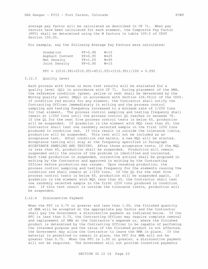
UAS Hangar - FY15 - Fort Carson, Colorado FCW9
average pay factor will be calculated as described in CP 71. When pay factors have been calculated for each element, the Composite Pay Factor (PFC) shall be determined using the W factors in table 105-2 of CDOT Section 105.05.
For example, say the following Average Pay Factors were calculated:
Gradation PF=0.98 W=15 Asphalt Content PF=0.95 W=25 Mat Density PF=1.05 W=45 Joint Density PF=0.90 W=15
PFC = (15(0.98)+25(0.95)+45(1.05)+15(0.90))/100 = 0.992
3.12.3 Quality Level
Each process with three or more test results will be evaluated for a quality level (QL) in accordance with CP 71. During placement of the HMA, the reference condition (green, yellow or red) shall be determined by the Moving Quality Level (MQL) in accordance with Section 106.05(c) of the CDOT. If condition red exists for any element, the Contractor shall notify the Contracting Officer immmediately in writing and the process control sampling and testing frequency increased to a minimum rate of 1/250 tons for that element. The process control sampling and testing frequency shall remain at 1/250 tons until the process control QL reaches or exceeds 78. If the QL for the next five process control tests is below 65, production will be suspended. If gradation is the element with MQL less than 65, the Contractor shall test one randomly selected sample in the first 1250 tons produced in condition red. If this result is outside the tolerance limits, production will be suspended. This test will not be included as an acceptance test. After condition red exists, a new MQL will be started. Acceptance testing will stay at the frequency specified in Paragraph ACCEPTANCE SAMPLING AND TESTING. After three acceptance tests, if the MQL is less than 65, production shall be suspended. Production will remain suspended until the source of the problem is identified and corrected. Each time production is suspended, corrective actions shall be proposed in writing by the Contractor and approved in writing by the Contracting Officer before production may resume. Upon resuming production, the process control sampling and testing frequency for the elements causing the condition red shall remain at 1/250 tons. If the QL for the next five process control tests is below 65, production will be suspended again. If gradation is the element with MQL less than 65, the Contractor shall test one randomly selected sample in the first 1250 tons produced in condition red. If this test result is outside the tolerance limits, production will be suspended.
3.12.4 Disincentive Payment
When the PFC is 0.75 or greater and less than 1.00, the finished quantity of HMA will be accepted at the appropriate pay factor and the Contractor shall pay the Government a disincentive payment as indicated below. If the PFC is less than 0.75, the Contracting Officer may require complete removal and replacement of HMA at the Contractor's expense or, where the finished product is determined by the Contracting Officer to be capable of perfoming the intended purpose and the value of the finished product is not affected, the Government may allow the Contractor to leave the HMA in place. If the material is permitted to remain in place, the PFC for HMA will not be greater than 0.75. When the PFC is 1.00 or greater, a disincentive payment will not be required. The Government will not provide incentive payments
SECTION 32 12 16 Page 23

UAS Hangar - FY15 - Fort Carson, Colorado FCW9
to the Contractor when the PFC exceeds 1.00.
DP Computation (PF<1.00):
DP = (1-PFC)(QR)(UP)
Where: DP = Disincentive Payment PFC = Composite Pay Factor QR = Quantity in Tons of HMA represented by the process UP = Unit Bid Price of HMA
-- End of Section --
SECTION 32 12 16 Page 24

UAS Hangar - FY15 - Fort Carson, Colorado FCW9
SECTION TABLE OF CONTENTS
DIVISION 32 - EXTERIOR IMPROVEMENTS
SECTION 32 13 11
CONCRETE PAVEMENT FOR AIRFIELDS AND OTHER HEAVY-DUTY PAVEMENTS
11/12
PART 1 GENERAL
1.1 UNIT PRICES 1.1.1 Measurements 1.1.2 Payments 1.1.2.1 Lump Sum 1.1.3 Payment of Lots 1.1.4 Payment Adjustment for Smoothness 1.1.5 Payment Adjustment for Plan Grade 1.1.6 Payment Adjustment for Thickness 1.2 REFERENCES 1.3 SYSTEM DESCRIPTION 1.3.1 Surface Smoothness 1.3.2 Edge Slump and Joint Face Deformation 1.3.3 Plan Grade 1.3.4 Flexural Strength 1.3.5 Thickness 1.3.6 Diamond Grinding of PCC Surfaces 1.4 SUBMITTALS 1.5 QUALITY CONTROL 1.5.1 Contractor Quality Control Staff 1.5.2 Other Staff 1.5.3 Laboratory Accreditation 1.5.4 Preconstruction Testing of Materials 1.5.4.1 Aggregates 1.5.4.2 Chemical Admixtures, Curing Compounds and Epoxies 1.5.4.3 Cementitious Materials 1.5.5 Testing During Construction 1.5.6 Test Section 1.5.6.1 Pilot Lane 1.5.6.2 Fill-In Lane 1.5.7 Acceptability of Work 1.5.8 Acceptance Requirements 1.5.8.1 Pavement Lots 1.5.8.2 Evaluation 1.6 DELIVERY, STORAGE, AND HANDLING 1.6.1 Bulk Cementitious Materials 1.6.2 Aggregate Materials 1.6.3 Other Materials
PART 2 PRODUCTS
2.1 CEMENTITIOUS MATERIALS 2.1.1 Portland Cement 2.1.2 Blended Cements 2.1.3 Pozzolan
SECTION 32 13 11 Page 1

UAS Hangar - FY15 - Fort Carson, Colorado FCW9
2.1.3.1 Fly Ash 2.1.3.2 Raw or Calcined Natural Pozzolan 2.1.3.3 Ultra Fine Fly Ash and Ultra Fine Pozzolan 2.1.4 Ground Granulated Blast-Furnace (GGBF) Slag 2.1.5 Supplementary Cementitious Materials (SCM) Content 2.2 AGGREGATES 2.2.1 Aggregate Sources 2.2.1.1 Durability 2.2.1.2 Alkali-Silica Reactivity 2.2.1.3 Combined Aggregate Gradation 2.2.2 Coarse Aggregate 2.2.2.1 Material Composition 2.2.2.2 Particle Shape Characteristics 2.2.2.3 Size and Grading 2.2.2.4 Deleterious Materials - Airfield Pavements 2.2.2.5 Testing Sequence/Deleterious Materials in Coarse Aggregate
- Airfields Only 2.2.3 Fine Aggregate 2.2.3.1 Composition 2.2.3.2 Grading 2.2.3.3 Deleterious Material 2.3 CHEMICAL ADMIXTURES 2.3.1 General Requirements 2.3.2 Lithium Nitrate 2.4 MEMBRANE FORMING CURING COMPOUND 2.5 WATER 2.6 JOINT MATERIALS 2.6.1 Expansion Joint Material 2.7 REINFORCING 2.7.1 Reinforcing Bars and Bar Mats 2.7.2 Welded Wire Reinforcement 2.8 DOWELS 2.8.1 Dowels 2.8.2 Dowel Bar Assemblies 2.9 EPOXY RESIN 2.10 EQUIPMENT 2.10.1 Batching and Mixing Plant 2.10.2 Concrete Mixers 2.10.3 Transporting Equipment 2.10.4 Transfer and Spreading Equipment 2.10.5 Paver-Finisher 2.10.6 Curing Equipment 2.10.7 Texturing Equipment 2.10.8 Sawing Equipment 2.10.9 Straightedge 2.11 SPECIFIED CONCRETE STRENGTH AND OTHER PROPERTIES 2.11.1 Specified Flexural Strength 2.11.2 Concrete Temperature 2.11.3 Concrete Strength for Final Acceptance 2.12 MIXTURE PROPORTIONS 2.12.1 Composition 2.12.2 Proportioning Studies 2.12.2.1 Water-Cement Ratio 2.12.2.2 Trial Mixture Studies 2.12.2.3 Mixture Proportioning for Flexural Strength 2.12.3 Average CQC Flexural Strength Required for Mixtures
PART 3 EXECUTION
SECTION 32 13 11 Page 2
UAS Hangar - FY15 - Fort Carson, Colorado FCW9
3.1 PREPARATION FOR PAVING 3.1.1 Weather Precaution 3.1.2 Proposed Techniques 3.2 CONDITIONING OF UNDERLYING MATERIAL 3.2.1 General Procedures 3.2.2 Traffic on Underlying Material 3.3 WEATHER LIMITATIONS 3.3.1 Placement and Protection During Inclement Weather 3.3.2 Paving in Hot Weather 3.3.3 Prevention of Plastic Shrinkage Cracking 3.3.4 Paving in Cold Weather 3.4 CONCRETE PRODUCTION 3.4.1 Batching and Mixing Concrete 3.4.2 Transporting and Transfer - Spreading Operations 3.5 PAVING 3.5.1 General Requirements 3.5.2 Consolidation 3.5.3 Operation 3.5.4 Required Results 3.5.5 Fixed Form Paving 3.5.5.1 Forms for Fixed-Form Paving 3.5.5.2 Form Removal 3.5.6 Slipform Paving 3.5.6.1 General 3.5.6.2 Guideline for Slipform Paving 3.5.6.3 Laser Controls 3.5.7 Placing Reinforcing Steel 3.5.7.1 Pavement Thickness Greater Than 12 Inches 3.5.7.2 Pavement Thickness Less Than 12 Inches 3.5.8 Placing Dowels 3.5.8.1 Contraction Joints 3.5.8.2 Construction Joints-Fixed Form Paving 3.5.8.3 Dowels Installed in Hardened Concrete 3.5.8.4 Lubricating Dowel Bars 3.6 FINISHING 3.6.1 Machine Finishing With Fixed Forms 3.6.2 Machine Finishing with Slipform Pavers 3.6.3 Surface Correction and Testing 3.6.4 Hand Finishing 3.6.4.1 Equipment and Template 3.6.4.2 Finishing and Floating 3.6.5 Texturing 3.6.5.1 Burlap Drag Surface 3.6.6 Edging 3.6.7 Outlets in Pavement 3.7 CURING 3.7.1 Protection of Concrete 3.7.2 Membrane Curing 3.8 JOINTS 3.8.1 General Requirements for Joints 3.8.2 Longitudinal Construction Joints 3.8.3 Transverse Construction Joints 3.8.4 Expansion Joints 3.8.5 Contraction Joints 3.8.6 Thickened Edge Joints 3.9 REPAIR, REMOVAL AND REPLACEMENT OF NEWLY CONSTRUCTED SLABS 3.9.1 General Criteria 3.9.2 Slabs with Cracks 3.9.3 Removal and Replacement of Full Slabs
SECTION 32 13 11 Page 3

UAS Hangar - FY15 - Fort Carson, Colorado FCW9
3.9.4 Repairing Spalls Along Joints 3.9.5 Repair of Weak Surfaces 3.9.6 Repair of Pilot Lane Vertical Faces 3.10 EXISTING CONCRETE PAVEMENT REMOVAL AND REPAIR 3.10.1 Removal of Existing Pavement Slab 3.10.2 Edge Repair 3.10.2.1 Spall Repair 3.10.2.2 Underbreak and Underlying Material 3.11 PAVEMENT PROTECTION 3.12 TESTING AND INSPECTION FOR CONTRACTOR QUALITY CONTROL 3.12.1 Testing and Inspection by Contractor 3.12.2 Testing and Inspection Requirements 3.12.3 Concrete Strength Testing for Contractor CQC 3.12.4 Reports
-- End of Section Table of Contents --
SECTION 32 13 11 Page 4

UAS Hangar - FY15 - Fort Carson, Colorado FCW9
SECTION 32 13 11
CONCRETE PAVEMENT FOR AIRFIELDS AND OTHER HEAVY-DUTY PAVEMENTS11/12
PART 1 GENERAL
1.1 UNIT PRICES
1.1.1 Measurements
The quantity of concrete to be paid for will be the volume of concrete in cubic yards including thickened edges, where required, placed in the completed and accepted pavement. Concrete will be measured in place in the completed and accepted pavement only within the neat line dimensions shown in the plan and cross section. No deductions will be made for rounded or beveled edges or the space occupied by pavement reinforcement, dowel bars, or electrical conduits, nor for any void, or other structure extending into or through the pavement slab, measuring 3 cubic feet or less in volume. No other allowance for concrete will be made unless placed in specified locations in accordance with written instructions previously issued by the Contracting Officer. The quantity of other materials specified herein, and used in the construction of the work covered by this section, will not be measured for payment, but will be considered a subsidiary obligation of the Contractor, covered under the price per cubic yard for concrete. Joint sealing materials are covered in Section 32 01 19 FIELD MOLDED SEALANTS FOR SEALING JOINTS IN RIGID PAVEMENTS.
1.1.2 Payments
1.1.2.1 Lump Sum
The quantity of concrete will be paid for and included in the lump-sum contract price. If less than 100 percent payment is due based on the pay factors stipulated below, a unit price of $300 per cubic yard will be used for purposes of calculating the payment reduction.
1.1.3 Payment of Lots
When a lot of material fails to meet the specification requirements, that lot will be accepted at a reduced price or shall be removed and replaced. The lowest computed percent payment determined for any pavement characteristic (i.e., thickness, grade, and surface smoothness) discussed below shall be the actual percent payment for that lot. The actual percent payment will be applied to the unit price and the measured quantity of concrete in the lot to determine actual payment. Use results of strength tests to control concreting operations. Strength will be evaluated, but will not be considered for payment adjustment. Any pavement not meeting the required 'specified strength' shall be removed and replaced at no additional cost to the Government.
1.1.4 Payment Adjustment for Smoothness
a. Straightedge Testing: Location and deviation from straightedge for all measurements shall be recorded. When more than 5.0 and less than or equal to 10.0 percent of all measurements made within a lot exceed the
SECTION 32 13 11 Page 5

UAS Hangar - FY15 - Fort Carson, Colorado FCW9
tolerance specified in paragraph "Surface Smoothness", after any reduction of high spots or removal and replacement, the computed percent payment based on surface smoothness will be 95 percent. When more than 10.0 percent and less than or equal to 15.0 percent of all measurements exceed the tolerance, the computed percent payment will be 90 percent. When more than 15.0 and less than or equal to 20.0 percent of all measurements exceed the tolerance, the computed percent payment will be 75 percent. When more than 20.0 percent of the measurements exceed the tolerance, the lot shall be removed and replaced at no additional cost to the Government.
1.1.5 Payment Adjustment for Plan Grade
When more than 5.0 and less than or equal to 10.0 percent of all measurements made within a lot are outside the specified tolerance, the computed percent payment for that lot will be 95 percent. When more than 10.0 percent but less than 50 percent are outside the specified tolerances, the computed percent payment for the lot will be 75 percent. In any areas where the deviation from grade exceeds the specified tolerances by 50 percent or more, the deficient area shall be removed and replaced at no additional cost to the Government.
1.1.6 Payment Adjustment for Thickness
Using the Average Thickness of the lot, determine the computed percent payment for thickness by entering the following table:
Computed Percent Payment for Thickness
Deficiency in Thickness
Determined by coresInches
Pavements Equal To orOver 8 Inches Thick
Pavements Less Than 8Inches Thick
0.00 to 0.24 100 100
0.25 to 0.49 75 65
0.50 to 0.74 50 0
0.75 or greater 0 0
Where 0 percent payment is indicated, remove the entire lot and replace at no additional cost to the Government. Where either of the two cores from a sublot show a thickness deficiency of 0.75 inch or greater, [ 0.50 inch for pavements 8 inches or less in thickness] drill two more cores in the sublot and compute the average thickness of the four cores. If this average shows a thickness deficiency of 0.75 inch or more [ 0.50 inch for pavements 8 inches or less in thickness] remove the entire sublot.
1.2 REFERENCES
The publications listed below form a part of this specification to the extent referenced. The publications are referred to within the text by the
SECTION 32 13 11 Page 6

UAS Hangar - FY15 - Fort Carson, Colorado FCW9
basic designation only.
AMERICAN ASSOCIATION OF STATE HIGHWAY AND TRANSPORTATION OFFICIALS (AASHTO)
AASHTO M 182 (2005; R 2009) Standard Specification for Burlap Cloth Made from Jute or Kenaf and Cotton Mats
AMERICAN CONCRETE INSTITUTE INTERNATIONAL (ACI)
ACI 211.1 (1991; R 2009) Standard Practice for Selecting Proportions for Normal, Heavyweight and Mass Concrete
ACI 214R (2011) Evaluation of Strength Test Results of Concrete
ACI 305R (2010) Guide to Hot Weather Concreting
ACI 306R (2010) Guide to Cold Weather Concreting
ASTM INTERNATIONAL (ASTM)
ASTM A184/A184M (2006; E2011) Standard Specification for Fabricated Deformed Steel Bar Mats for Concrete Reinforcement
ASTM A185/A185M (2007) Standard Specification for Steel Welded Wire Reinforcement, Plain, for Concrete
ASTM A497/A497M (2007) Standard Specification for Steel Welded Wire Reinforcement, Deformed, for Concrete
ASTM A615/A615M (2013) Standard Specification for Deformed and Plain Carbon-Steel Bars for Concrete Reinforcement
ASTM A775/A775M (2007b) Standard Specification for Epoxy-Coated Steel Reinforcing Bars
ASTM A996/A996M (2009b) Standard Specification for Rail-Steel and Axle-Steel Deformed Bars for Concrete Reinforcement
ASTM C1017/C1017M (2007) Standard Specification for Chemical Admixtures for Use in Producing Flowing Concrete
ASTM C1064/C1064M (2011) Standard Test Method for Temperature of Freshly Mixed Hydraulic-Cement Concrete
ASTM C1077 (2014) Standard Practice for Laboratories Testing Concrete and Concrete Aggregates for Use in Construction and Criteria for Laboratory Evaluation
SECTION 32 13 11 Page 7
UAS Hangar - FY15 - Fort Carson, Colorado FCW9
ASTM C117 (2013) Standard Test Method for Materials Finer than 75-um (No. 200) Sieve in Mineral Aggregates by Washing
ASTM C123/C123M (2012) Standard Test Method for Lightweight Particles in Aggregate
ASTM C1240 (2011) Standard Specification for Silica Fume Used in Cementitious Mixtures
ASTM C1260 (2007) Standard Test Method for Potential Alkali Reactivity of Aggregates (Mortar-Bar Method)
ASTM C131 (2006) Standard Test Method for Resistance to Degradation of Small-Size Coarse Aggregate by Abrasion and Impact in the Los Angeles Machine
ASTM C136 (2006) Standard Test Method for Sieve Analysis of Fine and Coarse Aggregates
ASTM C138/C138M (2013) Standard Test Method for Density ("Unit Weight"), Yield, and Air Content (Gravimetric) of Concrete
ASTM C142/C142M (2010) Standard Test Method for Clay Lumps and Friable Particles in Aggregates
ASTM C143/C143M (2012) Standard Test Method for Slump of Hydraulic-Cement Concrete
ASTM C150/C150M (2012) Standard Specification for Portland Cement
ASTM C1567 (2011) Standard Test Method for Potential Alkali-Silica Reactivity of Combinations of Cementitious Materials and Aggregate (Accelerated Mortar-Bar Method)
ASTM C1602/C1602M (2012) Standard Specification for Mixing Water Used in Production of Hydraulic Cement Concrete
ASTM C1646/C1646M (2008a) Making and Curing Test Specimens for Evaluating Frost Resistance of Coarse Aggregate in Air-Entrained Concrete by Rapid Freezing and Thawing
ASTM C172/C172M (2010) Standard Practice for Sampling Freshly Mixed Concrete
ASTM C174/C174M (2006) Standard Test Method for Measuring Thickness of Concrete Elements Using Drilled Concrete Cores
ASTM C192/C192M (2007) Standard Practice for Making and Curing Concrete Test Specimens in the
SECTION 32 13 11 Page 8

UAS Hangar - FY15 - Fort Carson, Colorado FCW9
Laboratory
ASTM C231/C231M (2010) Standard Test Method for Air Content of Freshly Mixed Concrete by the Pressure Method
ASTM C260/C260M (2010a) Standard Specification for Air-Entraining Admixtures for Concrete
ASTM C29/C29M (2009) Standard Test Method for Bulk Density ("Unit Weight") and Voids in Aggregate
ASTM C294 (2005) Standard Descriptive Nomenclature for Constituents of Concrete Aggregates
ASTM C295/C295M (2012) Petrographic Examination of Aggregates for Concrete
ASTM C309 (2011) Standard Specification for Liquid Membrane-Forming Compounds for Curing Concrete
ASTM C31/C31M (2010) Standard Practice for Making and Curing Concrete Test Specimens in the Field
ASTM C33/C33M (2011a) Standard Specification for Concrete Aggregates
ASTM C39/C39M (2012) Standard Test Method for Compressive Strength of Cylindrical Concrete Specimens
ASTM C494/C494M (2011) Standard Specification for Chemical Admixtures for Concrete
ASTM C595/C595M (2012) Standard Specification for Blended Hydraulic Cements
ASTM C618 (2012) Standard Specification for Coal Fly Ash and Raw or Calcined Natural Pozzolan for Use in Concrete
ASTM C666/C666M (2003; R 2008) Resistance of Concrete to Rapid Freezing and Thawing
ASTM C78/C78M (2010) Standard Test Method for Flexural Strength of Concrete (Using Simple Beam with Third-Point Loading)
ASTM C88 (2005) Standard Test Method for Soundness of Aggregates by Use of Sodium Sulfate or Magnesium Sulfate
ASTM C881/C881M (2010) Standard Specification for Epoxy-Resin-Base Bonding Systems for Concrete
ASTM C94/C94M (2012) Standard Specification for
SECTION 32 13 11 Page 9

UAS Hangar - FY15 - Fort Carson, Colorado FCW9
Ready-Mixed Concrete
ASTM C989/C989M (2012) Standard Specification for Slag Cement for Use in Concrete and Mortars
ASTM D1751 (2004; R 2008) Standard Specification for Preformed Expansion Joint Filler for Concrete Paving and Structural Construction (Nonextruding and Resilient Bituminous Types)
ASTM D1752 (2004a; R 2008) Standard Specification for Preformed Sponge Rubber Cork and Recycled PVC Expansion
ASTM D2995 (1999; R 2009) Determining Application Rate of Bituminous Distributors
ASTM D3665 (2007e1) Random Sampling of Construction Materials
ASTM D4791 (2010) Flat Particles, Elongated Particles, or Flat and Elongated Particles in Coarse Aggregate
ASTM D75/D75M (2009) Standard Practice for Sampling Aggregates
ASTM E1274 (2003; R 2008) Standard Test Method for Measuring Pavement Roughness Using a Profilograph
NATIONAL READY MIXED CONCRETE ASSOCIATION (NRMCA)
NRMCA QC 3 (2003) Quality Control Manual: Section 3, Plant Certifications Checklist: Certification of Ready Mixed Concrete Production Facilities
STATE OF CALIFORNIA DEPARTMENT OF TRANSPORTATION (CALTRANS)
CTM 526 (2002) Operation of California Profilograph and Evaluation of Profiles
U.S. ARMY CORPS OF ENGINEERS (USACE)
COE CRD-C 130 (2001) Standard Recommended Practice for Estimating Scratch Hardness of Coarse Aggregate Particles
COE CRD-C 143 (1962) Specifications for Meters for Automatic Indication of Moisture in Fine Aggregate
COE CRD-C 300 (1990) Specifications for Membrane-Forming Compounds for Curing Concrete
COE CRD-C 521 (1981) Standard Test Method for Frequency and Amplitude of Vibrators for Concrete
SECTION 32 13 11 Page 10

UAS Hangar - FY15 - Fort Carson, Colorado FCW9
COE CRD-C 55 (1992) Test Method for Within-Batch Uniformity of Freshly Mixed Concrete
COE CRD-C 662 (2009) Determining the Potential Alkali-Silica Reactivity of Combinations of Cementitious Materials, Lithium Nitrate Admixture and Aggregate (Accelerated Mortar-Bar Method)
1.3 SYSTEM DESCRIPTION
This section is intended to stand alone for construction of concrete pavement. However, where the construction covered herein interfaces with other sections, the construction at each interface shall conform to the requirements of both this section and the other section, including tolerances for both.
1.3.1 Surface Smoothness
Use the straightedge method for longitudinal and transverse testing. Where drawings show required deviations from a plane surface (crowns, drainage inlets, etc.) or existing rough or high PI pavement, finish the surface to meet the approval of the Contracting Officer. Detailed notes shall be kept of the results of the testing and a copy furnished to the Government after each day's testing.
a. Straightedge Testing: The finished surfaces of the pavements shall have no abrupt change of 1/4 inch or more, and all pavements shall be within the limits specified when checked with an approved 12 foot straightedge. All airfield areas shall have a variation from a straight edge not greater than 1/4 inch in either the longitudinal or transverse direction.
c. Bumps ("Must Grind" Areas): Any bumps ("must grind" areas) shown on the profilograph trace which exceed 0.4 inch in height shall be reduced by diamond grinding in accordance with subparagraph "Diamond Grinding of PCC Surfaces" below until they do not exceed 0.3 inch when retested. Such grinding shall be tapered in all directions to provide smooth transitions to areas not requiring grinding.
d. Testing Method: After the concrete has hardened sufficiently to permit walking thereon, but not later than 48 hours after placement, test the entire surface of the pavement in each lot in such a manner as to reveal all surface irregularities exceeding the tolerances specified above. If any pavement areas are ground, these areas shall be retested immediately after diamond grinding. The entire area of the pavement shall be tested in both a longitudinal and a transverse direction on parallel lines. The transverse lines shall be 15 feet or less apart, as directed. The longitudinal lines shall be at the centerline of each paving lane shown on the drawings, regardless of whether the Contractor is allowed to pave two lanes at a time, and at the 1/8th point in from each side of the lane. Other areas having obvious deviations shall also be tested. Longitudinal testing lines shall be continuous across all joints. Transverse testing lines for pilot lanes shall be carried to construction joint lines and for fill-in lanes shall be carried 24 inches across construction joints, and the readings in this area
SECTION 32 13 11 Page 11

UAS Hangar - FY15 - Fort Carson, Colorado FCW9
applied to the fill-in lane. Straightedge testing of the longitudinal edges of slipformed pilot lanes shall also be performed before paving fill-in lanes as specified below.
(1) Straightedge Testing: The straightedge shall be held in contact with the surface and moved ahead one-half the length of the straightedge for each successive measurement. Determine the amount of surface irregularity by placing the freestanding (unleveled) straightedge on the pavement surface and measuring the maximum gap between the straightedge and the pavement surface. Measurements shall be determined along the entire length of the straight edge.
1.3.2 Edge Slump and Joint Face Deformation
a. Edge Slump: When slip-form paving is used, not more than 15.0 percent of the total free edge of each pavement panel shall have an edge slump exceeding 1/4 inch and none of the free edge of the pavement lot shall have an edge slump exceeding 3/8 inch. (A pavement panel is defined as a lane width by the length between two adjacent transverse contraction joints. The total free edge of the pavement will be considered to be the cumulative total linear measurement of pavement panel edge originally constructed as non-adjacent to any existing pavement; i.e., 100 feet of pilot lane originally constructed as a separate lane, will have 200 feet of free edge; 100 feet of fill-in lane will have no free edge, etc.,). The area affected by the downward movement of the concrete along the pavement edge shall not exceed 18 inches back from the edge.
b. Joint Face Deformation: In addition to the edge slump limits specified above, the vertical joint face shall have a surface within the maximum limits shown below:
Offset from Straightedge Applied Logintudinally to Pavement Surface
Offset from Straightedge Applied Longitudinally to Vertical Face
Offset from Straightedge Applied Top to Bottom Against the Joint Face
Abrupt Offset in Any Direction
Offset of Joint Face from True Vertical
Airfield Pavement
1/8 inch 1/4 inch 3/8 inch 1/8 inch 1 inch/12 inches
All Other Pavement
1/4 inch All other items same as airfield pavement
c. Slump Determination: Immediately after the concrete has hardened sufficiently to permit walking thereon, the pavement surface of each lot shall be tested by the Contractor. Testing shall be performed with a minimum 12 foot straightedge to reveal irregularities exceeding the edge slump tolerance specified above. The vertical edge slump shall be determined at each free edge of each slipformed paving lane constructed. The straightedge shall be placed transverse to the
SECTION 32 13 11 Page 12

UAS Hangar - FY15 - Fort Carson, Colorado FCW9
direction of paving and the end of the straightedge located at the edge of the paving lane. Measurements shall be made at 5 to 15 foot spacings, as directed, commencing at the header where paving was started. Initially measurements shall be made at 5 foot intervals in each lane. When no deficiencies are present, the Contracting Officer may approve an increase in the interval. When any deficiencies exist, the interval will be returned to 5 feet. In no case shall the interval exceed 15 feet. In addition to the transverse edge slump determination above, the Contractor, at the same time, shall check the longitudinal surface smoothness of the joint on a continuous line 1 inch back from the joint line using the 12 foot straightedge advanced one-half its length for each reading. Other tests of the exposed joint face shall be made to ensure that a uniform, true vertical joint face is attained. The measurements shall be made by the Contractor, shall be properly referenced in accordance with paving lane identification and stationing, and a report given to the Contracting Officer within 24 hours after measurement is made. The report shall also identify areas requiring replacement.
d. Excessive Edge Slump: When edge slump exceeding the limits specified above is encountered on either side of the paving lane, additional straightedge measurements shall be made, if required, to define the linear limits of the excessive slump. The concrete slabs having excessive edge slump or joint deformation shall be removed and replaced to the next transverse joint in conformance with paragraph: REPAIR, REMOVAL, REPLACEMENT OF NEWLY CONSTRUCTED SLABS. Use of slip-form paving equipment and procedures that fail to consistently provide edges within the specified tolerances on edge slump and joint face deformation shall be discontinued and the pavements shall be constructed by means of standard paving procedures using fixed forms.
1.3.3 Plan Grade
Within 5 days after paving of each lot, the finished surface of the pavement area shall be tested, by running lines of levels at intervals corresponding with every longitudinal and transverse joint to determine the elevation at each joint intersection. The results of this survey shall be recorded and a copy given to the Government at the completion of the survey of each lot. The finished surfaces of airfield runway, taxiway, and apron pavements shall vary not more than 1/2 inch above or below the plan grade line or elevation indicated. The surfaces of other pavements shall vary not more than 3/4 inch. The above deviations from the approved grade line and elevation will not be permitted in areas where closer conformance with the planned grade and elevation is required for the proper functioning of appurtenant structures. The finished surfaces of new abutting pavements shall coincide at their juncture.
1.3.4 Flexural Strength
Submit certified copies of laboratory test reports and sources for cement, supplementary cementitious materials (SCM), aggregates, admixtures, curing compound, epoxy, and proprietary patching materials proposed for use on this project. All aggregate tests shall have been performed no earlier than 6 months prior to contract award. Each lot of pavement will be evaluated for acceptance in accordance with the following procedures.
a. Sampling and Testing: For acceptance, one composite sample of concrete from each sublot shall be obtained in accordance with ASTM C172/C172M from one batch or truckload.[ Test beams 6 x 6 inches shall be
SECTION 32 13 11 Page 13

UAS Hangar - FY15 - Fort Carson, Colorado FCW9
fabricated and cured in accordance with ASTM C31/C31M; and tested in accordance with ASTM C78/C78M.]
b. Computations: Average the eight 14-day strength tests for the lot. The average strength shall be used in accordance with paragraph "Concrete Strength for Final Acceptance" in PART 2.
1.3.5 Thickness
Each lot of pavement will be evaluated for acceptance and payment adjustment in accordance with the following procedure. Two cores, between 4 and 6 inches in diameter, shall be drilled from the pavement, per sublot (8 per lot). The Contractor is responsible for drilling the cores within 3 days after lot placement, filling the core holes with an approved non-shrink concrete, respraying the cored areas with curing compound, and for measuring the cores. Each core shall be inspected for voids, thickness of paste on the surface, and depth of reinforcement (if required). Provide the results with the thickness measurement data. Eight measurements of thickness shall be made around the circumference of each core and one in the center, in accordance with ASTM C174/C174M, using calibrated calipers for specimens longer than 10 inches. The pavement thickness from the 8 cores for the lot shall be averaged and shall be evaluated as described in paragraph: PAYMENT ADJUSTMENT FOR THICKNESS above.
1.3.6 Diamond Grinding of PCC Surfaces
In areas not meeting the specified limits for surface smoothness and plan grade, high areas shall be reduced to attain the required smoothness and grade, except as depth is limited below. High areas shall be reduced by grinding the hardened concrete with an approved diamond grinding machine after the concrete is 14 days or more old. Grinding shall be accomplished by sawing with an industrial diamond abrasive which is impregnated in the saw blades. The saw blades shall be assembled in a cutting head mounted on a machine designed specifically for diamond grinding that will produce the required texture and smoothness level without damage to the concrete pavement or joint faces. The saw blades shall be 1/8-inch wide and there shall be a minimum of 55 to 60 blades per 12 inches of cutting head width depending on the hardness of the aggregate. Each machine shall be capable of cutting a path 3 to 4 ft 3 to 4 ft wide. Grinding equipment that causes ravels, aggregate fractures, spalls or disturbance to the joints will not be permitted. The area corrected by grinding the surface of the hardened concrete shall not exceed 10 percent of the total area of any sublot. The depth of diamond grinding shall not exceed 1/4 inch. All pavement areas requiring plan grade or surface smoothness corrections in excess of the limits specified above, shall be removed and replaced in conformance with paragraph REPAIR, REMOVAL, REPLACEMENT OF NEWLY CONSTRUCTED SLABS. All areas in which diamond grinding has been performed will be subject to the thickness tolerances specified in paragraph: Thickness, above.
1.4 SUBMITTALS
Government approval is required for submittals with a "G" designation; submittals not having a "G" designation are for information only. When used, a designation following the "G" designation identifies the office that will review the submittal for the Government. Submit the following in accordance with Section 01 33 00 SUBMITTAL PROCEDURES:
SD-03 Product Data
SECTION 32 13 11 Page 14

UAS Hangar - FY15 - Fort Carson, Colorado FCW9
EquipmentProposed Techniques; G, PODowels; G, PODowel Bar Assemblies; G, PO
SD-05 Design Data
Proportioning Studies; G, DO
SD-06 Test Reports
Sampling and Testing; G, DO
SD-07 Certificates
Contractor Quality Control Staff; G, DOLaboratory Accreditation; G, DONRMCA Certificate of Conformance; G, DOCommercial Laboratory; G, DO
1.5 QUALITY CONTROL
1.5.1 Contractor Quality Control Staff
Submit American Concrete Institute certification for Contractor Quality Control staff. Qualifications and resumes for petrographer, surveyor, concrete batch plant operator, and profilograph operator. All Contractor Quality Control personnel assigned to concrete construction shall be American Concrete Institute (ACI) certified in the following grade (or shall have written evidence acceptable to the Contracting Officer's representative of having completed similar qualification programs):
a. CQC personnel responsible for inspection of concrete paving operations: ACI Concrete Transportation Inspector. The ACI Concrete Inspector shall be present at the paving site at all times paving is ongoing.
b. Lead Foreman or Journeyman of the Concrete Placing, Finishing, and Curing Crews: ACI Concrete Flatwork Technician/Finisher.
c. Field Testing Technicians: ACI Concrete Field Testing Technician, Grade I.
d. Laboratory Testing Technicians: ACI Concrete Strength Testing Technician and Laboratory Testing Technician, Grade I or II.
1.5.2 Other Staff
Submit for approval, the qualifications and resumes for the following staff:
a. Petrographer: Bachelor of Science degree in geology or petrography, trained in petrographic examination of concrete aggregate according to ASTM C294 and ASTM C295/C295M and trained in identification of the specific deleterious materials and tests identified in this specification. Resume shall detail the education, training and experience related to the project-specific test methods and deleterious materials and shall be submitted at least 20 days before petrographic and deleterious materials examination is to commence.
SECTION 32 13 11 Page 15

UAS Hangar - FY15 - Fort Carson, Colorado FCW9
b. Licensed Surveyor: All survey work shall be performed under the supervision of a Licensed Surveyor.
c. Concrete Batch Plant Operator: National Ready Mix Concrete Association (NRMCA) Plant Manager certification at the Plant Operator level.
1.5.3 Laboratory Accreditation
Laboratory and testing facilities shall be provided by and at the expense of the Contractor. Submit accreditation of the commercial laboratory by an independent evaluation authority, indicating conformance to ASTM C1077, including all applicable test procedures. The laboratories performing the tests shall be accredited in accordance with ASTM C1077, including ASTM C78/C78M and ASTM C1260. The accreditation shall be current and shall include the required and optional test methods, as specified throughout this Section. Onsite temperature-controlled concrete curing facilities shall be provided.
a. Aggregate Testing and Mix Proportioning: Aggregate testing and mixture proportioning studies shall be performed by a commercial laboratory.
b. Acceptance Testing: Furnish all materials, labor, and facilities required for molding, curing, testing, and protecting test specimens at the site and in the laboratory. Steel molds shall be used for molding the beam specimens. Furnish and maintain boxes or other facilities suitable for storing and curing the specimens at the site while in the mold within the temperature range stipulated by ASTM C31/C31M. Flexural loading equipment shall be in accordance with ASTM C78/C78M.
c. Contractor Quality Control: All sampling and testing shall be performed by an approved, onsite, independent, commercial laboratory, or for cementitious materials and admixtures, the manufacturer's laboratory. Submit USACE validation letter for commercial laboratory.
d. Laboratory Inspection: The Government will inspect the laboratory equipment and test procedures prior to the start of concreting operations for conformance to ASTM C1077. The laboratory shall maintain this certification for the duration of the project.
1.5.4 Preconstruction Testing of Materials
All sampling and testing shall be performed by, and at the expense of, the Contractor. Use an approved commercial laboratory or, for cementitious materials and chemical admixtures, a laboratory maintained by the manufacturer of the material. No material shall be used until notice of acceptance has been given. The Contractor will not be entitled to any additional payment or extension of time due to failure of any material to meet project requirements, or for any additional sampling or testing required. Additional tests may be performed by the Government at the discretion of the Contracting Officer; such Government testing will not relieve the Contractor of any testing responsibilities.
1.5.4.1 Aggregates
Aggregates shall be sampled in the presence of a Government Representative. Samples shall be obtained in accordance with ASTM D75/D75M and shall be representative of the materials to be used for the project.
SECTION 32 13 11 Page 16

UAS Hangar - FY15 - Fort Carson, Colorado FCW9
Test results shall be submitted 7 days before commencing mixture proportioning studies.
1.5.4.2 Chemical Admixtures, Curing Compounds and Epoxies
At least 30 days before the material is used, submit certified copies of test results for the specific lots or batches to be used on the project. Test results shall be not more than 6 months old prior to use in the work. Chemical admixtures that have been in storage at the project site for longer than 6 months or that have been subjected to freezing will be retested at the expense of the Contractor and will be rejected if test results are not satisfactory.
1.5.4.3 Cementitious Materials
Cement, ground granulated blast furnace (GGBF) slag, and pozzolan will be accepted on the basis of manufacturer's certification of compliance, accompanied by mill test reports showing that the material in each shipment meets the requirements of the specification under which it is furnished. Mill test reports shall be no more than 1 month old, prior to use in the work. No cementitious material shall be used until notice of acceptance has been given by the Contracting Officer. Cementitious material may be subjected to testing by the Government from samples obtained at the mill, at transfer points, or at the project site. If tests prove that a cementitious material that has been delivered is unsatisfactory, it shall be promptly removed from the site of the work. Cementitious material that has not been used within 6 months after testing shall be retested at the Contractor's expense and shall be rejected if test results are not satisfactory.
1.5.5 Testing During Construction
During construction, the Contractor is responsible for sampling and testing aggregates, cementitious materials, and concrete as specified herein. The Government will sample and test concrete and ingredient materials as considered appropriate. Provide facilities and labor as may be necessary for procurement of representative test samples. Testing by the Government will in no way relieve the Contractor of the specified testing requirements.
1.5.6 Test Section
Up to 10 days, but not more than 60 days, prior to construction of the concrete pavement, construct a test section as part of the production paving area at a location determined by the Contracting Officer. Use the test section to develop and demonstrate to the satisfaction of the Contracting Officer the proposed techniques of mixing, hauling, placing, consolidating, finishing, curing, initial saw cutting, start-up procedures, testing methods, plant operations, and the preparation of the construction joints. Variations in mixture proportions, other than water, shall be made if directed. Vary the water content, as necessary, to arrive at the appropriate content. The mixing plant shall be operated and calibrated prior to start of placing the test section. Use the same equipment, materials, and construction techniques on the test section as will be used in all subsequent work. Base course preparation, concrete production, placing, consolidating, curing, construction of joints, and all testing shall be in accordance with applicable provisions of this specification. Three days after completion of the test section, provide eight cores at least 6 inch diameter by full depth cut from points selected in the test section by the Government. The cores will be evaluated for homogeneity,
SECTION 32 13 11 Page 17

UAS Hangar - FY15 - Fort Carson, Colorado FCW9
consolidation and segregation. Construct the test section meeting all specification requirements and being acceptable to the Contracting Officer in all aspects, including surface texture. Failure to construct an acceptable test section will necessitate construction of additional test sections at no additional cost to the Government. Test sections allowed to be constructed as part of the production paving which do not meet specification requirements shall be removed at the Contractor's expense. If the Contractor proposes to use slipform paving and is unable to construct an acceptable test section, the slipform paving equipment shall be removed from the job and the construction completed using stationary side forms and equipment compatible with them. Production paving shall not commence until the results on aggregates and concrete, including evaluation of the cores, and all pavement measurements for edge slump, joint face deformation, actual plan grade, surface smoothness and thickness have been submitted and approved by the Contracting Officer. Pavement accepted as a production lot will be evaluated and paid in accordance with Paragraph: ACCEPTABILITY OF WORK below.
1.5.6.1 Pilot Lane
The test section shall consist of one paving lane at least 150 feet long and shall be constructed to the same thickness as the thickest portion of pavement shown on the Drawings. The lane width shall be the same as that required for use in the project. The test section shall contain at least one transverse construction joint. If doweled longitudinal construction joints are required in any of the production pavements, they shall be installed full length along one side of the test strip throughout the test section. Two separate days shall be used for construction of the test section.
1.5.6.2 Fill-In Lane
The first 150 feet of the initial production fill-in lane shall be considered a fill-in lane test section for purposes of testing and evaluation. All requirements for the test section are applicable, as appropriate. Obtain cores from the fill-lane lane side of the longitudinal construction joint with the pilot lane. The cores will be evaluated for homogeneity, consolidation, and segregation.
1.5.7 Acceptability of Work
The materials and the pavement itself will be accepted on the basis of tests made by the Contractor. The Government may make check tests to validate the results of the Contractor's testing. If the results of the Contractor tests vary by less than 2.0 percent of the Government's test results, the results of the Contractor's tests will be used. If the results of the Government and Contractor tests vary by 2.0 percent, but less than 4.0 percent, the average of the two will be considered the value to be used. If these vary by 4.0 percent or more, each sampling and testing procedure shall be carefully evaluated and both the Government and the Contractor shall take another series of tests on duplicate samples of material. If these vary by 4.0 percent or more, the results of the tests made by the Government shall be used and the Government will continue check testing of this item on a continuous basis until the two sets of tests agree within less than 4.0 percent on a regular basis. Testing performed by the Government will in no way at any time relieve the Contractor from the specified testing requirements.
SECTION 32 13 11 Page 18

UAS Hangar - FY15 - Fort Carson, Colorado FCW9
1.5.8 Acceptance Requirements
1.5.8.1 Pavement Lots
A lot will be that quantity of construction that will be evaluated for acceptance with specification requirements. A lot will be equal to one shift of production not to exceed 1000 cubic yards. In order to evaluate thickness, each lot will be divided into four equal sublots. Grade determinations will be made on the lot as a whole. Surface smoothness determinations will be made on every 0.1 mile segment in each lot. Location of all samples shall be selected on a random basis in accordance with ASTM D3665. When operational conditions cause a lot to be terminated before the specified four sublots have been completed, the following procedure shall be used to adjust the lot size and number of tests for the lot. Where three sublots have been completed, they shall constitute a lot. Where one or two sublots have been completed, they shall be incorporated into the next lot (except for the last lot), and the total number of sublots shall be used and acceptance criteria adjusted accordingly.
1.5.8.2 Evaluation
Provide all sampling and testing required for acceptance and payment adjustment at the Contractor's expense. Individuals performing sampling, testing and inspection duties shall meet the required Qualifications. The Contracting Officer reserves the right to direct additional samples and tests for any area which appears to deviate from the specification requirements. Testing in these areas will be in addition to the sublot or lot testing, and the requirements for these areas will be the same as those for a sublot or lot. Provide facilities for and, where directed, personnel to assist in obtaining samples for any Government testing.
1.6 DELIVERY, STORAGE, AND HANDLING
1.6.1 Bulk Cementitious Materials
Furnish all cementitious material in bulk. The temperature of the cementitious material, as delivered to storage at the site, shall not exceed 150 degrees F. Sufficient cementitious materials shall be in storage to sustain continuous operation of the concrete mixing plant while the pavement is being placed. Provide separate facilities to prevent any intermixing during unloading, transporting, storing, and handling of each type of cementitious material.
1.6.2 Aggregate Materials
Store aggregate at the site of the batching and mixing plant avoiding breakage, segregation, intermixing or contamination by foreign materials. Each size of aggregate from each source shall be stored separately in free-draining stockpiles. Aggregate stored on ground shall have a minimum 24 inch thick sacrificial layer left undisturbed. Fine aggregate and the smallest size coarse aggregate shall remain in free-draining storage for at least 24 hours immediately prior to use. Sufficient aggregate shall be maintained at the site at all times to permit continuous uninterrupted operation of the mixing plant at the time concrete pavement is being placed. Tracked equipment shall not be allowed on coarse aggregate stockpiles.
SECTION 32 13 11 Page 19

UAS Hangar - FY15 - Fort Carson, Colorado FCW9
1.6.3 Other Materials
Store reinforcing bars and accessories above the ground on supports. All materials shall be stored avoiding contamination and deterioration.
PART 2 PRODUCTS
2.1 CEMENTITIOUS MATERIALS
Cementitious materials shall be portland cement, [blended cement] or only portland cement in combination with supplementary cementitious materials (SCM), and shall conform to appropriate specifications listed below. New submittals are required when the cementitious materials sources or types change.
2.1.1 Portland Cement
Provide portland cement conforming to ASTM C150/C150M, Type I or II, low alkali including false set requirements
2.1.2 Blended Cements
Blended cement shall conform to ASTM C595/C595M, Type IP or IS, including the optional requirement for mortar expansion and sulfate soundness. The pozzolan added to the Type IP blend shall be ASTM C618 Class F or Class N and shall be interground with the cement clinker. The manufacturer shall state in writing that the amount of pozzolan in the finished cement will not vary more than plus or minus 5 mass percent of the finished cement from lot to lot or within a lot. The percentage and type of mineral admixture used in the blend shall not change from that submitted for the aggregate evaluation and mixture proportioning. The requirements of Table 2 in paragraph SUPPLEMENTARY CEMENTITIOUS MATERIALS (SCM) CONTENT do not apply to the SCM content of blended cement.
2.1.3 Pozzolan
2.1.3.1 Fly Ash
Fly ash shall conform to ASTM C618, Class F, including the optional requirements for uniformity and effectiveness in controlling Alkali-Silica reaction and shall have a loss on ignition not exceeding 3 percent. Class F fly ash for use in mitigating Alkali-Silica Reactivity shall have a total equivalent alkali content less than 3 percent.
2.1.3.2 Raw or Calcined Natural Pozzolan
Natural pozzolan shall be raw or calcined and conform to ASTM C618, Class N, including the optional requirements for uniformity and effectiveness in controlling Alkali-Silica reaction and shall have a loss on ignition not exceeding 3 percent. Class N pozzolan for use in mitigating Alkali-Silica Reactivity shall have a total equivalent alkali content less than 3 percent.
2.1.3.3 Ultra Fine Fly Ash and Ultra Fine Pozzolan
Ultra Fine Fly Ash (UFFA) and Ultra Fine Pozzolan (UFP) shall conform to ASTM C618, Class F or N, and the following additional requirements:
a. The strength activity index at 28 days of age shall be at least 95 percent of the control specimens.
SECTION 32 13 11 Page 20

UAS Hangar - FY15 - Fort Carson, Colorado FCW9
b. The average particle size shall not exceed 6 microns.
2.1.4 Ground Granulated Blast-Furnace (GGBF) Slag
Ground Granulated Blast-Furnace Slag shall conform to ASTM C989/C989M, Grade 100 or Grade 120.
2.1.5 Supplementary Cementitious Materials (SCM) Content
The Contractor may elect to use one of the SCMs listed below, unless the SCM is required to mitigate ASR. The use of SCMs is encouraged in accordance with Section 01 62 35, Recycled/Recovered Materials.
TABLE 2SUPPLEMENTARY CEMENTITIOUS MATERIALS CONTENT
Supplementary Cementitious Material Minimum Content(percent)
Maximum Content(percent)
Class N Pozzolan and Class F Fly Ash
SiO2 + Al2O3 + Fe2O3 > 70% 25 35
SiO2 + A12O3 + Fe2O3 > 80% 20 35
SiO2 + A12O3 + Fe2O3 > 90% 15 35
UFFA and UFP 7 16
GGBF Slag 40 50
2.2 AGGREGATES
2.2.1 Aggregate Sources
2.2.1.1 Durability
Aggregate shall have a satisfactory service record in freezing and thawing of at least 5 years successful service in three concrete paving projects. The service record shall include a condition survey of the existing concrete and a review of the concrete-making materials, including coarse and fine aggregates, cement, and mineral admixtures. This review should consider the previous aggregate source and test results, cement mill certificate data, mineral admixture chemical and physical composition, and the mix design (cement factor and water-cementitious material ratio). Aggregate not having a satisfactory demonstrable service record shall have a durability factor of 50 or more when subjected to freezing and thawing of specimens prepared in accordance with ASTM C1646/C1646M and tested in accordance with ASTM C666/C666M, Procedure A.
2.2.1.2 Alkali-Silica Reactivity
Fine and coarse aggregates to be used in all concrete shall be evaluated and tested for alkali-aggregate reactivity. All size groups and sources proposed for use shall be tested.
SECTION 32 13 11 Page 21

UAS Hangar - FY15 - Fort Carson, Colorado FCW9
a. The fine and coarse aggregates shall be evaluated separately, using ASTM C1260. Test results of the individual aggregates shall have a measured expansion equal to or less than 0.08 percent after 28 days of immersion in a 1N NaOH solution. Should the test data indicate an expansion of greater than 0.08 percent, the aggregate(s) shall be rejected or additional testing shall be performed as follows: utilize the Contractor's proposed low alkali portland cement, blended cement, and/or SCM, and/or Lithium Nitrate in combination with each individual aggregate. If only SCMs are being evaluated, the testing shall be in accordance with ASTM C1567. If Lithium Nitrate is being evaluated, with or without SCMs, the testing shall be in accordance with COE CRD-C 662. Determine the quantity that will meet all the requirements of these specifications and that will lower the expansion equal to or less than 0.08 percent after 28 days of immersion in a 1N NaOH solution. Mixture proportioning shall be based on the highest percentage of SCM required to mitigate ASR-reactivity
b. If any of the above options does not lower the expansion to less than 0.08 percent after 28 days of immersion in a 1N NaOH solution, reject the aggregate(s) and submit new aggregate sources for retesting. Submit the results of testing to the Contracting Officer for evaluation and acceptance.
2.2.1.3 Combined Aggregate Gradation
In addition to the grading requirements specified for coarse aggregate and for fine aggregate, the combined aggregate grading shall meet the following requirements:
a. The materials selected and the proportions used shall be such that when the Coarseness Factor (CF) and the Workability Factor (WF) are plotted on a diagram as described in d. below, the point thus determined shall fall within the parallelogram described therein.
b. The Coarseness Factor (CF) shall be determined from the following equation:
CF = (cumulative percent retained on the 3/8 in. sieve)(100)/(cumulative percent retained on the No. 8 sieve)
c. The Workability Factor WF is defined as the percent passing the No. 8 sieve based on the combined gradation. However, WF shall be adjusted, upwards only, by 2.5 percentage points for each 94 pounds of cementitious material per cubic yard greater than 564 pounds per cubic yard.
d. A diagram shall be plotted using a rectangular scale with WF on the Y-axis with units from 20 (bottom) to 45 (top), and with CF on the X-axis with units from 80 (left side) to 30 (right side). On this diagram a parallelogram shall be plotted with corners at the following coordinates (CF-75, WF-28), (CF-75, WF-40), (CF-45, WF-32.5), and (CF-45, WF-44.5). If the point determined by the intersection of the computed CF and WF does not fall within the above parallelogram, the grading of each size of aggregate used and the proportions selected shall be changed as necessary.)
SECTION 32 13 11 Page 22

UAS Hangar - FY15 - Fort Carson, Colorado FCW9
2.2.2 Coarse Aggregate
2.2.2.1 Material Composition
Coarse aggregate shall consist of crushed or uncrushed gravel, or crushed stone,or a combination thereof. Aggregates, as delivered to the mixers, shall consist of clean, hard, uncoated particles meeting the requirements of ASTM C33/C33M except as specified herein. Coarse aggregate shall be washed. Washing shall be sufficient to remove dust and other coatings. Coarse aggregate shall not show more than 40 percent loss when subjected to the Los Angeles abrasion test in accordance with ASTM C131. The sodium sulfate soundness loss shall not exceed 12 percent, or the magnesium sulfate soundness loss shall not exceed 18 percent after five cycles when tested in accordance with ASTM C88.
2.2.2.2 Particle Shape Characteristics
Particles of the coarse aggregate shall be generally spherical or cubical in shape. The quantity of flat and elongated particles in any size group coarser than the3/8 inch sieve shall not exceed 20 percent by weight as determined by the Flat Particle Test and the Elongated Particle Test of ASTM D4791. A flat particle is defined as one having a ratio of width to thickness greater than 3; an elongated particle is one having a ratio of length to width greater than 3.
2.2.2.3 Size and Grading
The nominal maximum size of the coarse aggregate shall be 1.5 inch. Grade and furnish the individual aggregates in two size groups meeting the individual grading requirements of ASTM C33/C33M, Size No. 4 (1.5 to 0.75 inches) and Size No. 67 (0.75 inches to No. 4) to meet the coarseness and workability factor criteria for the contractor-proposed combined gradation. A third aggregate size group may be required to meet the above mentioned coarseness and workability criteria of paragraph COMBINED AGGREGATE GRADATION.
2.2.2.4 Deleterious Materials - Airfield Pavements
The amount of deleterious material in each size group of coarse aggregate shall not exceed the limits shown in Table 5 below, determined in accordance with the test methods shown.
TABLE 5
LIMITS OF DELETERIOUS MATERIALS IN COARSE AGGREGATE FOR AIRFIELDPAVEMENTS
Percentage by Mass
Materials (h)
Clay lumps and friable particles (ASTM C142/C142M)
0.2
Shale (a) (ASTM C295/C295M) 0.1
Material finer than No. 200 sieve (b) (ASTM C117)
0.5
SECTION 32 13 11 Page 23

UAS Hangar - FY15 - Fort Carson, Colorado FCW9
TABLE 5
LIMITS OF DELETERIOUS MATERIALS IN COARSE AGGREGATE FOR AIRFIELDPAVEMENTS
Percentage by Mass
Materials (h)
Lightweight particles (c) (ASTM C123/C123M)
0.2
Clay ironstone (d) (ASTM C295/C295M)
0.1
Chert and cherty stone (less than 2.40 Sp. Gr.) (e) (ASTM C123/C123M and ASTM C295/C295M)
0.1
Claystone, mudstone, and siltstone (f) (ASTM C295/C295M)
0.1
Shaly and argillaceous limestone (g) (ASTM C295/C295M)
0.2
Other soft particles (COE CRD-C 130)
1.0
Total of all deleterious substances exclusive of material finer than No. 200 sieve
1.0
(a) Shale is defined as a fine-grained, thinly laminated or fissile sedimentary rock. It is commonly composed of clay or silt or both. It has been indurated by compaction or by cementation, but not so much as to have become slate.
(b) Limit for material finer than No. 200 sieve will be increased to 1.5 percent for crushed aggregates if the fine material consists of crusher dust that is essentially free from clay or shale. Use XRD or other appropriate techniques as determined by the petrographer to
tif th t(c) The separation medium shall have a density of Sp. Gr. of 2.0. This limit does not apply to coarse aggregate manufactured from blast-furnace slag unless contamination is evident.
(d) Clay ironstone is defined as an impure variety of iron carbonate, iron oxide, hydrous iron oxide, or combinations thereof, commonly mixed with clay, silt, or sand. It commonly occurs as dull, earthy particles, homogeneous concretionary masses, or hard-shell particles with soft interiors. Other names commonly used for clay ironstone are "chocolate bars" and limonite concretions.
(e) Chert is defined as a rock composed of quartz, chalcedony or opal, or any mixture of these forms of silica. It is variable in color. The texture is so fine that the individual mineral grains are too small to be distinguished by the unaided eye. Its hardness is such that it scratches glass but is not scratched by a knife blade. It may contain impurities such as clay, carbonates, iron oxides, and other minerals. Cherty stone is defined as any type of rock (generally limestone) that contains chert as lenses and nodules, or irregular masses partially or completely replacing the original stone.
SECTION 32 13 11 Page 24

UAS Hangar - FY15 - Fort Carson, Colorado FCW9
TABLE 5
LIMITS OF DELETERIOUS MATERIALS IN COARSE AGGREGATE FOR AIRFIELDPAVEMENTS
Percentage by Mass
Materials (h)
(f) Claystone, mudstone, or siltstone, is defined as a massive fine-grained sedimentary rock that consists predominantly of indurated clay or silt without laminations or fissility. It may be indurated either by compaction or by cementation.
(g) Shaly limestone is defined as limestone in which shale occurs as one or more thin beds or laminae. These laminae may be regular or very irregular and may be spaced from a few inches down to minute fractions of an inch. Argillaceous limestone is defined as a limestone in which clay minerals occur disseminated in the stone in the amount of 10 to 50 percent by weight of the rock; when these make up from 50 to 90 percent, the rock is known as calcareous (or dolomitic) shale (or claystone, mudstone, or siltstone).
(h) Perform testing in accordance with the referenced test methods, except that the minimum sample size shall be as specified below.
2.2.2.5 Testing Sequence/Deleterious Materials in Coarse Aggregate - Airfields Only
The Contractor will not be entitled to any extension of time or additional payment due to any delays caused by the testing, evaluation, or personnel requirements. The size of the coarse aggregate sample shall be at least 200 pounds for the 3/4 inch and larger maximum size and 25 pounds for the No. 4 to 3/4 inch coarse aggregate and 10 pounds for the fine aggregate. Provide facilities for the ready procurement of representative test samples. The testing procedure on each sample of coarse aggregate for compliance with limits on deleterious materials shall be as follows:
Step 1: Wash each full sample of coarse aggregate for material finer than the No. 200 sieve. Discard material finer than the No. 200 sieve.
Step 2: Test remaining full sample for clay lumps and friable particles and remove.
Step 3: Test remaining full sample for lightweight particles (Sp. Gr. 2.0) and remove.
Step 4. Test remaining full sample for chert and/or cherty stone with SSD density of less than 2.40 specific gravity. Remove lightweight chert and/or cherty stone. Restore other materials less than 2.40 to the sample.
Step 5: Test remaining sample for clay-ironstone, shale, claystone, mudstone, siltstone, shaly and/or argillaceous limestone, and remove.
Step 6: Test approximately one-fifth of remaining full sample for other soft particles.
SECTION 32 13 11 Page 25

UAS Hangar - FY15 - Fort Carson, Colorado FCW9
2.2.3 Fine Aggregate
2.2.3.1 Composition
Fine aggregate shall consist of natural sand, manufactured sand, or a combination of the two, and shall be composed of clean, hard, durable particles meeting the requirements of ASTM C33/C33M. Each type of fine aggregate shall be stockpiled and batched separately. Particles of the fine aggregate shall be generally spherical or cubical in shape.
2.2.3.2 Grading
Grading of the fine aggregate, as delivered to the mixer, shall conform to the requirements of ASTM C33/C33M and shall have a fineness modulus of not less than 2.50 nor more than 3.40.
2.2.3.3 Deleterious Material
Sample size for fine aggregate proposed for use in airfield paving shall be 10 pounds. The amount of deleterious material in the fine aggregate shall not exceed the following limits by mass:
Material Percentage by Mass
Clay lumps and friable particles ASTM C142/C142M 1.0
Material finer than No. 200 sieve ASTM C117 3.0
Lightweight particles ASTM C123/C123M using a medium with a density of Sp. Gr. of 2.0
0.5
Total of all above 3.0
2.3 CHEMICAL ADMIXTURES
2.3.1 General Requirements
Chemical admixtures may only be used when the specific admixture type and manufacturer is the same material used in the mixture proportioning studies. The air-entraining admixture shall conform to ASTM C260/C260M. An accelerator conforming to ASTM C494/C494M, Type C, may be used only when specified in paragraph: SPECIFIED CONCRETE STRENGTH AND OTHER PROPERTIES below and shall not be used to reduce the amount of cementitious material used. Calcium chloride and admixtures containing calcium chloride shall not be used. Retarding or water-reducing admixture shall meet the requirements of ASTM C494/C494M, Type A, B, or D, except that the 6-month and 1-year compressive strength tests are waived. ASTM C494/C494M, Type F and G high range water reducing admixtures and ASTM C1017/C1017M flowable admixtures shall not be used.
2.3.2 Lithium Nitrate
The lithium admixture shall be a nominal 30 percent aqueous solution of Lithium Nitrate, with a density of 10 pounds/gallon, and shall have the approximate chemical form as shown below:
SECTION 32 13 11 Page 26

UAS Hangar - FY15 - Fort Carson, Colorado FCW9
Constituent Limit (Percent by Mass)
LiNo3 (Lithium Nitrate) 30 +/- 0.5
SO4-2 (Sulfate Ion) 0.1 (max)
Cl- (Chloride Ion) 0.2 (max)
Na+ (Sodium Ion) 0.1 (max)
K+ (Potassium Ion) 0.1 (max)
Provide a trained representative to supervise the lithium nitrate admixture dispensing and mixing operations.
2.4 MEMBRANE FORMING CURING COMPOUND
Membrane forming curing compound shall be a white pigmented compound conforming to COE CRD-C 300.
2.5 WATER
Water for mixing shall be fresh, clean, potable, and free of injurious amounts of oil, acid, salt, or alkali, except that non-potable water, or water from concrete production operations, may be used if it meets the requirements of ASTM C1602/C1602M.
2.6 JOINT MATERIALS
2.6.1 Expansion Joint Material
Expansion joint filler shall be a preformed material conforming to ASTM D1751 or ASTM D1752 Type II or III. Expansion joint filler shall be 3/4 inch thick, unless otherwise indicated, and shall be furnished in a single full depth piece.
2.7 REINFORCING
All reinforcement shall be free from loose, flaky rust, loose scale, oil, grease, mud, or other coatings that might reduce the bond with concrete. Removal of thin powdery rust and tight rust is not required. However, reinforcing steel which is rusted to the extent that it does not conform to the required dimensions or mechanical properties shall not be used.
2.7.1 Reinforcing Bars and Bar Mats
Reinforcing bars shall conform to ASTM A615/A615M, billet-steel or ASTM A996/A996M, rail and axle steel, Grade 60. Bar mats shall conform to ASTM A184/A184M. The bar members may be billet rail or axle steel.
2.7.2 Welded Wire Reinforcement
Welded Wire Reinforcement shall be deformed or smooth, conforming to ASTM A497/A497Mor ASTM A185/A185M, and shall be furnished in flat sheets.
SECTION 32 13 11 Page 27

UAS Hangar - FY15 - Fort Carson, Colorado FCW9
2.8 DOWELS
2.8.1 Dowels
Dowels shall be single piece bars fabricated or cut to length at the shop or mill before delivery to the site. Dowels shall be free of loose, flaky rust and loose scale and shall be clean and straight. Dowels may be sheared to length provided that the deformation from true shape caused by shearing does not exceed 0.04 inch on the diameter of the dowel and does not extend more than 0.04 inch from the end of the dowel. Dowels shall be plain (non-deformed) steel bars conforming to ASTM A615/A615M, Grade 40 or 60; ASTM A996/A996M, Grade 50 or 60. Dowel bars shall be epoxy coated in conformance with ASTM A775/A775M, to include the ends. Grout retention rings shall be fully circular metal or plastic devices capable of supporting the dowel until the epoxy hardens. Dowel sleeves or inserts are not permitted.
2.8.2 Dowel Bar Assemblies
Dowel bar assemblies shall consist of a framework of metal bars or wires arranged to provide rigid support for the dowels throughout the paving operation, with a minimum of four continuous bars or wires extending along the joint line. The dowels shall be welded to the assembly or held firmly by mechanical locking arrangements that will prevent them from rising, sliding out, or becoming distorted during paving operations.
2.9 EPOXY RESIN
All epoxy-resin materials shall be two-component materials conforming to the requirements of ASTM C881/C881M, Class as appropriate for each application temperature to be encountered, except that in addition, the materials shall meet the following requirements:
a. Material for use for embedding dowels and anchor bolts shall be Type IV, Grade 3.
b. Material for use as patching materials for complete filling of spalls and other voids and for use in preparing epoxy resin mortar shall be Type III, Grade as approved.
c. Material for use for injecting cracks shall be Type IV, Grade 1.
d. Material for bonding freshly mixed portland cement concrete or mortar or freshly mixed epoxy resin concrete or mortar to hardened concrete shall be Type V, Grade as approved.
2.10 EQUIPMENT
All plant, equipment, tools, and machines used in the work shall be maintained in satisfactory working conditions at all times. Submit the following:
a. Details and data on the batching and mixing plant prior to plant assembly including manufacturer's literature showing that the equipment meets all requirements specified herein.
b. Obtain National Ready Mixed Concrete Association (NRMCA) certification of the concrete plant. The concrete plant shall be inspected by an engineer approved by the NRMCA. A list of NRMCA approved engineers is
SECTION 32 13 11 Page 28
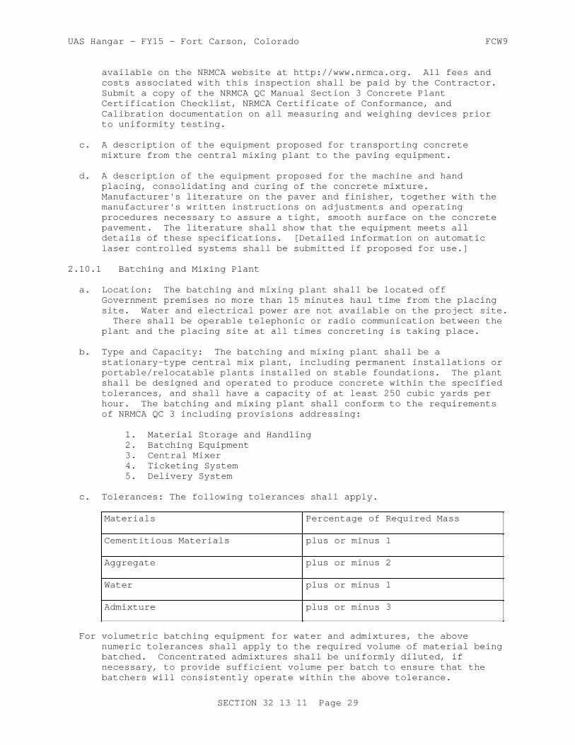
UAS Hangar - FY15 - Fort Carson, Colorado FCW9
available on the NRMCA website at http://www.nrmca.org. All fees and costs associated with this inspection shall be paid by the Contractor. Submit a copy of the NRMCA QC Manual Section 3 Concrete Plant Certification Checklist, NRMCA Certificate of Conformance, and Calibration documentation on all measuring and weighing devices prior to uniformity testing.
c. A description of the equipment proposed for transporting concrete mixture from the central mixing plant to the paving equipment.
d. A description of the equipment proposed for the machine and hand placing, consolidating and curing of the concrete mixture. Manufacturer's literature on the paver and finisher, together with the manufacturer's written instructions on adjustments and operating procedures necessary to assure a tight, smooth surface on the concrete pavement. The literature shall show that the equipment meets all details of these specifications. [Detailed information on automatic laser controlled systems shall be submitted if proposed for use.]
2.10.1 Batching and Mixing Plant
a. Location: The batching and mixing plant shall be located off Government premises no more than 15 minutes haul time from the placing site. Water and electrical power are not available on the project site. There shall be operable telephonic or radio communication between the plant and the placing site at all times concreting is taking place.
b. Type and Capacity: The batching and mixing plant shall be a stationary-type central mix plant, including permanent installations or portable/relocatable plants installed on stable foundations. The plant shall be designed and operated to produce concrete within the specified tolerances, and shall have a capacity of at least 250 cubic yards per hour. The batching and mixing plant shall conform to the requirements of NRMCA QC 3 including provisions addressing:
1. Material Storage and Handling2. Batching Equipment3. Central Mixer4. Ticketing System5. Delivery System
c. Tolerances: The following tolerances shall apply.
Materials Percentage of Required Mass
Cementitious Materials plus or minus 1
Aggregate plus or minus 2
Water plus or minus 1
Admixture plus or minus 3
For volumetric batching equipment for water and admixtures, the above numeric tolerances shall apply to the required volume of material being batched. Concentrated admixtures shall be uniformly diluted, if necessary, to provide sufficient volume per batch to ensure that the batchers will consistently operate within the above tolerance.
SECTION 32 13 11 Page 29
UAS Hangar - FY15 - Fort Carson, Colorado FCW9
d. Moisture Control: The plant shall be capable of ready adjustment to compensate for the varying moisture contents of the aggregates and to change the quantities of the materials being batched. An electric moisture meter complying with the provisions of COE CRD-C 143 shall be provided for measuring of moisture in the fine aggregate. The sensing element shall be arranged so that measurement is made near the batcher charging gate of the fine aggregate bin or in the fine aggregate batcher.
2.10.2 Concrete Mixers
a. General: Mixers shall be stationary or truck mixers. Mixers shall be capable of combining the materials into a uniform mixture and of discharging this mixture without segregation. The mixers shall not be charged in excess of the capacity recommended by the manufacturer. The mixers shall be operated at the drum or mixing blade speed designated by the manufacturer. The mixers shall be maintained in satisfactory operating condition, and the mixer drums shall be kept free of hardened concrete. Mixer blades or paddles shall be replaced when worn down more than 10 percent of their depth when compared with the manufacturer's dimension for new blades or paddles.
b. Stationary: Stationary mixers shall be drum or pan mixers. Mixers shall be provided with an acceptable device to lock the discharge mechanism until the required mixing time has elapsed.
c. Mixing Time and Uniformity for Stationary Mixers: For stationary mixers, before uniformity data are available, the mixing time for each batch after all solid materials are in the mixer, provided that all of the mixing water is introduced before one-fourth of the mixing time has elapsed, shall be 1 minute for mixers having a capacity of 1 cubic yard. For mixers of greater capacity, this minimum time shall be increased 20 seconds for each additional 1.33 cubic yard or fraction thereof. After results of uniformity tests are available, the mixing time may be reduced to the minimum time required to meet uniformity requirements; but if uniformity requirements are not being met, the mixing time shall be increased as directed. The mixing time for full batch production shall be a minimum of 75 seconds. Mixer performance tests at new mixing times shall be performed immediately after any change in mixing time. The Regular Test sequence shall be conducted for initial determination of the mixing time or as directed. When regular testing is performed, the concrete shall meet the limits of any five of the six uniformity requirements listed in Table 1 below.
d. The Abbreviated Test sequence shall be conducted for production concrete verification at the frequency specified in Table 6. When abbreviated testing is performed, the concrete shall meet only those requirements listed for abbreviated testing. The approved mix design proportions shall be used for uniformity testing. Regular testing shall consist of performing all six tests on three batches of concrete. The range for regular testing shall be the average of the ranges of the three batches. Abbreviated testing shall consist of performing the three required tests on a single batch of concrete. The range for abbreviated testing shall be the range for one batch. If more than one mixer is used and all are identical in terms of make, type, capacity, condition, speed of rotation, etc., the results of tests on one of the mixers shall apply to the others, subject to the approval of the Contracting Officer. All mixer performance
SECTION 32 13 11 Page 30

UAS Hangar - FY15 - Fort Carson, Colorado FCW9
(uniformity) testing shall be performed in accordance with COE CRD-C 55 and with paragraph titled TESTING AND INSPECTION FOR CONTRACTOR QUALITY CONTROL in PART 3.
TABLE 1 UNIFORMITY REQUIREMENTS--STATIONARY MIXERS
Parameter Regular Tests Allowable Maximum Range for Average of 3 Batches
Abbreviated Tests Allowable Maximum Range for 1 Batch
Unit weight of air-free mortar
2.0 lbs/cubic ft 2.0 lbs/cubic ft
Air content 1.0 percent --
Slump 1.0 inch 1.0 inch
Coarse aggregate 6.0 percent 6.0 percent
Compressive strength at 7 days
10.0 percent 10.0 percent
Water content 1.5 percent
e. Truck: Truck mixers shall not be used for mixing or transporting slipformed paving concrete. The only truck mixers used for mixing or transporting paving concrete shall be those designed with extra large blading and rear opening specifically for low-slump paving concrete. Truck mixers, the mixing of concrete therein, and concrete uniformity and testing thereof shall conform to the requirements of ASTM C94/C94M. The number of revolutions between 70 to 100 for truck-mixed concrete and the number of revolutions for shrink-mixed concrete shall be determined by uniformity tests as specified in ASTM C94/C94M and in requirements for mixer performance stated in paragraph TESTING AND INSPECTION FOR CONTRACTOR QUALITY CONTROL in PART 3. If requirements for the uniformity of concrete are not met with 100 revolutions of mixing after all ingredients including water are in the truck mixer drum, the mixer shall not be used until the condition is corrected. Water shall not be added after the initial introduction of mixing water except, when on arrival at the job site, the slump is less than specified and the water-cement ratio is less than that given as a maximum in the approved mixture. Additional water may be added to bring the slump within the specified range provided the approved water-cement ratio is not exceeded. Water shall be injected into the head of the mixer (end opposite the discharge opening) drum under pressure, and the drum or blades shall be turned a minimum of 30 additional revolutions at mixing speed. Water shall not be added to the batch at any later time. Mixer performance (uniformity) tests for truck mixers shall be made in accordance with ASTM C94/C94M.
2.10.3 Transporting Equipment
Slipform concrete shall be transported to the paving site in nonagitating equipment conforming to ASTM C94/C94M or in approved agitators. Fixed form concrete shall be transported in approved truck mixers designed with extra large blading and rear opening specifically for low slump concrete. All transporting equipment shall be designed and operated to deliver and discharge the required concrete mixture completely without segregation.
SECTION 32 13 11 Page 31

UAS Hangar - FY15 - Fort Carson, Colorado FCW9
2.10.4 Transfer and Spreading Equipment
Equipment for transferring concrete from the transporting equipment to the paving lane in front of the paver shall be specially manufactured, self-propelled transfer equipment which will accept the concrete outside the paving lane and will transfer and spread it evenly across the paving lane in front of the paver and strike off the surface evenly to a depth which permits the paver to operate efficiently.
2.10.5 Paver-Finisher
The following items a through e apply to both fixed-form and slip-form paver-finishers. Item f is applicable to fixed-form paver-finishers and item g is applicable to slip-form paver-finishers.
a. General: The paver-finisher shall be a heavy-duty, self-propelled machine designed specifically for paving and finishing high quality pavement. The paver-finisher shall weigh at least 2200 lb/foot of lane width, and shall be powered by an engine having at least 6.0 horsepower/foot of lane width. The paver-finisher shall spread, consolidate, and shape the plastic concrete to the desired cross section in one pass. The mechanisms for forming the pavement shall be easily adjustable in width and thickness and for required crown. In addition to other spreaders required by paragraph above, the paver-finisher shall be equipped with a full width knock-down auger or paddle mechanism, capable of operating in both directions, which will evenly spread the fresh concrete in front of the screed or extrusion plate.
b. Vibrators: Immersion vibrators shall be gang mounted at the front of the paver on a frame equipped with suitable controls so that all vibrators can be operated at any desired depth within the slab or completely withdrawn from the concrete, as required. The vibrators shall be automatically controlled so that they will be immediately stopped as forward motion of the paver ceases. [The paver-finisher shall be equipped with an electronic vibrator monitoring device displaying the operating frequency of each individual internal vibrator. The monitoring device shall have a readout display visible to the paver operator. It shall operate continuously while paving, and shall display all vibrator frequencies with manual or automatic sequencing among all individual vibrators.] The spacing of the immersion vibrators across the paving lane shall be as necessary to properly consolidate the concrete, but the clear distance between vibrators shall not exceed 30 inches. The outside vibrators shall not be more than 12 inches from the lane edge. Spud vibrators shall operate at a frequency of not less than 8000 impulses/minute and an amplitude of not less than 0.03 inch, as determined by COE CRD-C 521.
c. Screed or Extrusion Plate: The paver-finisher shall be equipped with a transversely oscillating screed or an extrusion plate to shape, compact, and smooth the surface and shall so finish the surface that no significant amount of hand finishing, except use of cutting straightedges, is required. The screed or extrusion plate shall be constructed to provide adjustment for crown in the pavement. The entire machine shall provide adjustment for variation in lane width or thickness and to prevent more than 8 inches of the screed or extrusion plate extending over previously placed concrete on either end when paving fill-in lanes. Machines that cause displacement of properly
SECTION 32 13 11 Page 32

UAS Hangar - FY15 - Fort Carson, Colorado FCW9
installed forms or cause ruts or indentations in the prepared underlying materials and machines that cause frequent delays due to mechanical failures shall be replaced as directed.
d. Longitudinal Mechanical Float: A longitudinal mechanical float may be used. If used, the float shall be specially designed and manufactured to smooth and finish the pavement surface without working excess paste to the surface. It shall be rigidly attached to the rear of the paver-finisher or to a separate self-propelled frame spanning the paving lane. The float plate shall be at least 5 feet long by 8 inches wide and shall automatically be oscillated in the longitudinal direction while slowly moving from edge to edge of the paving lane, with the float plate in contact with the surface at all times.
e. Other Types of Finishing Equipment: Clary screeds, other rotating tube floats, or bridge deck finishers are not allowed on mainline paving, but may be allowed on irregular or odd-shaped slabs, and near buildings or trench drains, subject to the Contracting Officer's approval. Bridge deck finishers shall have a minimum operating weight of 7500 pounds and shall have a transversely operating carriage containing a knock-down auger and a minimum of two immersion vibrators. Vibrating screeds or pans shall be used only for isolated slabs where hand finishing is permitted as specified, and only where specifically approved.
f. Fixed Forms: The paver-finisher shall be equipped with wheels designed to ride the forms, keep it aligned with the forms, and spread the load so as to prevent deformation of the forms. Paver-finishers traveling on guide rails located outside the paving lane shall be equipped with wheels when traveling on new or existing concrete to remain.
g. Slipform: The slipform paver-finisher shall be automatically controlled and crawler mounted with padded tracks so as to be completely stable under all operating conditions. The paver-finisher shall finish the surface and edges so that no edge slump beyond allowable tolerance occurs. Suitable moving side forms shall be provided that are adjustable and will produce smooth, even edges, perpendicular to the top surface and meeting specification requirements for alignment and freedom from edge slump.
2.10.6 Curing Equipment
Equipment for applying membrane-forming curing compound shall be mounted on a self-propelled frame that spans the paving lane. The reservoir for curing compound shall be constantly mechanically (not air) agitated during operation and shall contain means for completely draining the reservoir. The spraying system shall consist of a mechanically powered pump which will maintain constant pressure during operation, an operable pressure gauge, and either a series of spray nozzles evenly spaced across the lane to give uniformly overlapping coverage or a single spray nozzle which is mounted on a carriage which automatically traverses the lane width at a speed correlated with the forward movement of the overall frame. All spray nozzles shall be protected with wind screens. Calibrate the spraying system in accordance with ASTM D2995, Method A, for the rate of application required in paragraph: Membrane Curing. Any hand-operated sprayers allowed by that paragraph shall be compressed air supplied by a mechanical air compressor. If the curing equipment fails to apply an even coating of compound at the specified rate, it shall immediately be replaced.
SECTION 32 13 11 Page 33
UAS Hangar - FY15 - Fort Carson, Colorado FCW9
2.10.7 Texturing Equipment
a. General: Texturing equipment shall be as specified below. Before use, the texturing equipment shall be demonstrated on a test section, and the equipment shall be modified as necessary to produce the texture directed.
b. Burlap Drag: A burlap drag shall be securely attached to a separate wheel mounted frame spanning the paving lane or to one of the other similar pieces of equipment. Length of the material shall provide 24 to 36 inches dragging flat on the pavement surface. Width shall be at least equal to the width of the slab. The material shall be clean, reasonably new burlap, completely saturated with water before attachment to the frame, always resaturated before start of use, and kept clean and saturated during use. Burlap shall conform to AASHTO M 182, Class 3 or 4.
2.10.8 Sawing Equipment
Equipment for sawing joints and for other similar sawing of concrete shall be standard diamond-type concrete saws mounted on a wheeled chassis which can be easily guided to follow the required alignment. Blades shall be diamond tipped. If demonstrated to operate properly, abrasive blades may be used. Provide spares as required to maintain the required sawing rate. [Wheel saws used in the removal of concrete shall be saws with large diameter tungsten carbide tipped blades mounted on a heavy-duty chassis which will produce a saw kerf at least 1-1/2 inch wide.] All saws shall be capable of sawing to the full depth required. Early-entry saws may be used, subject to demonstration and approval of the Contracting Officer. No change to the initial sawcut depth shall be permitted.
2.10.9 Straightedge
Furnish and maintain at the job site, in good condition, one 12 foot straightedge for each paving train for testing the hardened portland cement concrete surfaces. These straightedges shall be constructed of aluminum or magnesium alloy and shall have blades of box or box-girder cross section with flat bottom, adequately reinforced to insure rigidity and accuracy. Straightedges shall have handles for operation on the pavement.
2.11 SPECIFIED CONCRETE STRENGTH AND OTHER PROPERTIES
2.11.1 Specified Flexural Strength
Specified flexural strength, R, for concrete is 650 psi at 90 days, as determined by [tests made in accordance with ASTM C78/C78M of beams fabricated and cured in accordance with ASTM C192/C192M] Maximum allowable water-cementitious material ratio is 0.45. The water-cementitious material ratio will be the equivalent water-cement ratio as determined by conversion from the weight ratio of water to cement plus SCM by the mass equivalency method described in ACI 211.1. The concrete shall be air-entrained with a total air content of 6 plus or minus 1.5 percentage points, at the point of placement. Air content shall be determined in accordance with ASTM C231/C231M. The maximum allowable slump of the concrete at the point of placement shall be 2 inches for pavement constructed with fixed forms. For slipformed pavement, at the start of the project, select a maximum allowable slump which will produce in-place pavement meeting the specified
SECTION 32 13 11 Page 34

UAS Hangar - FY15 - Fort Carson, Colorado FCW9
tolerances for control of edge slump. The selected slump shall be applicable to both pilot and fill-in lanes.
2.11.2 Concrete Temperature
The temperature of the concrete as delivered shall conform to the requirements of paragraphs, Paving in Hot Weather and Paving in Cold Weather, in PART 3. Temperature of concrete shall be determined in accordance with ASTM C1064/C1064M.
2.11.3 Concrete Strength for Final Acceptance
, The strength of the concrete will be considered acceptable when the equivalent 90-day flexural strengths for each lot are above the'Specified Flexural Strength' as determined by correlation with 14-day flexural strength tests specified in paragraph: "Mixture Proportioning for Flexural Strength" below, and no individual set (2 specimens per sublot) in the lot are 25 psi or more below the equivalent 'Specified Flexural Strength'. If any lot or sublot, respectively, fails to meet the above criteria, the lot or sublot shall be removed and replaced at no additional cost to the Government. This is in addition to and does not replace the average strength required for day-to-day CQC operations as specified in paragraph: Average CQC Flexural Strength Required for Mixtures, below.
2.12 MIXTURE PROPORTIONS
2.12.1 Composition
Concrete shall be composed of cementitious material, water, fine and coarse aggregates, and admixtures. Supplementary Cementitious Materials (SCM) choice and usage shall be in accordance with paragraph: Supplementary Cementitious Materials (SCM) Content. The total cementitious material content shall be at least 517 lb./cu. yd.. Admixtures shall consist of air entraining admixture and may also include, as approved, accelerator, retarder or water-reducing admixture.
2.12.2 Proportioning Studies
Trial design batches, mixture proportioning studies, and testing requirements are the responsibility of the Contractor. Submit the results of the mixture proportioning studies signed and stamped by the registered professional engineer having technical responsibility for the mix design study, and submitted at least 30 days prior to commencing concrete placing operations. The results shall include a statement giving the maximum nominal coarse aggregate size and the weights and volumes of each ingredient proportioned on a one cubic yard basis. Aggregate quantities shall be based on the mass in a saturated surface dry condition. The recommended mixture proportions shall be accompanied by test results demonstrating that the proportions selected will produce concrete of the qualities indicated. Trial mixtures having proportions, slumps, and air content suitable for the work shall be based on methodology described in ACI 211.1, modified as necessary to accommodate flexural strength. Submit test results including:
a. Coarse and fine aggregate gradations and plots.b. Combined aggregate gradation and coarseness/workability plots.c. Coarse aggregate quality test results, include deleterious materials.d. Fine aggregate quality test results.e. Mill certificates for cement and supplemental cementitious materials.
SECTION 32 13 11 Page 35
UAS Hangar - FY15 - Fort Carson, Colorado FCW9
f. Certified test results for air entraining, water reducing, retarding, non-chloride accelerating, and Lithium Nitrate admixtures.g. Specified flexural strength, slump, and air content.h. Documentation of required average CQC flexural strength, Ra.i. Recommended proportions/volumes for proposed mixture and each of three trial water-cementitious materials ratios.j. Individual beam breaks.k. Flexural strength summaries and plots.l. Correlation ratios for acceptance testing and CQC testing.m. Historical record of test results, documenting production standard deviation (if available).n. Narrative discussing methodology on how the mix design was developed.o. Alternate aggregate blending to be used during the test section if necessary to meet the required surface and consolidation requirements.
2.12.2.1 Water-Cement Ratio
At least three different water-cement ratios, which will produce a range of strength encompassing that required on the project, shall be used. The maximum allowable water-cement ratio required in paragraph: Specified Flexural Strength, above will be the equivalent water-cement ratio. Laboratory trial mixtures shall be proportioned for maximum permitted slump and air content. The maxiumum water-cementitious materials ratio of the approved mix design shall become the maximum water-cementitious materials ratio for all concrete production, and in no case shall exceed 0.45.
2.12.2.2 Trial Mixture Studies
Separate sets of trial mixture studies shall be made for each combination of cementitious materials and each combination of admixtures proposed for use. No combination of either shall be used until proven by such studies, except that, if approved in writing and otherwise permitted by these specifications, an accelerator or a retarder may be used without separate trial mixture study. Separate trial mixture studies shall also be made for concrete for each placing method (slip form, fixed form, or hand placement) proposed. The temperature of concrete in each trial batch shall be reported. Each mixture shall be designed to promote easy and suitable concrete placement, consolidation and finishing, and to prevent segregation and excessive bleeding. Laboratory trial mixtures shall be proportioned for maximum permitted slump and air content.
2.12.2.3 Mixture Proportioning for Flexural Strength
The following step by step procedure shall be followed:
a. Fabricate all beams for each mixture from the same batch or blend of batches. Fabricate and cure all beams in accordance with ASTM C192/C192M, using 6 x 6 inch steel beam forms.
b. Cure test beams from each mixture for 3, 7, 14, and 90-day flexural tests; 6 beams to be tested per age.
c. Test beams in accordance with ASTM C78/C78M.
d. Using the average strength for each w/c at each age, plot all results from each of the three mixtures on separate graphs for w/c versus:
3-day flexural strength7-day flexural strength
SECTION 32 13 11 Page 36
UAS Hangar - FY15 - Fort Carson, Colorado FCW9
14-day flexural strength
90-day flexural strength
e. From these graphs select a w/c that will produce a mixture giving a 90-day flexural strength equal to the required strength determined in accordance with the next paragraph.
f. Using the above selected w/c, select from the graphs the expected 3, 7 and 14-day flexural strengths.
g. From the above expected strengths for the selected mixture, determine the Ratio of the 7-day flexural strength of the selected mixture to the 90-day flexural strength of the mixture (for CQC control).
h. From the above expected strengths for the selected mixture, determine the Ratio of the 14-day flexural strength of the selected mixture to the 90-day flexural strength of the mixture (for acceptance).
i. If there is a change in materials, additional mixture design studies shall be made using the new materials and new Correlation Ratios shall be determined.
j. No concrete pavement shall be placed until the Contracting Officer has approved the Contractor's mixture proportions. The approved water-cementitious materials ratio shall not exceed the maximum value specified in paragraph: Specified Flexural Strength, above and shall not be increased without the Contracting Officer's written approval.
2.12.3 Average CQC Flexural Strength Required for Mixtures
In order to ensure meeting the strength requirements specified in paragraph: SPECIFIED CONCRETE STRENGTH AND OTHER PROPERTIES above, during production, the mixture proportions selected during mixture proportioning studies and used during construction shall produce a required average CQC flexural strength exceeding the specified strength, R, by the amount indicated below. This required average CQC flexural strength, Ra, will be used only for CQC operations as specified in paragraph: TESTING AND INSPECTION FOR CONTRACTOR QUALITY CONTROL in PART 3 and as specified in the previous paragraph. During production, the required Ra shall be adjusted , as appropriate and as approved, based on the standard deviation of average 90-day strengths being attained during paving.
a. From Previous Test Records: Where a concrete production facility has previous test records current to within 18 months, a standard deviation shall be established in accordance with the applicable provisions of ACI 214R. Test records from which a standard deviation is calculated shall represent materials, quality control procedures, and conditions similar to those expected, shall represent concrete produced to meet a specified flexural strength or strengths within 150 psi of the 90-day flexural strength specified for the proposed work, and shall consist of at least 30 consecutive tests. Perform verification testing, as directed by the Contracting Officer, to document the current strength. A strength test shall be the average of the strengths of two specimens made from the same sample of concrete and tested at 90 days. Required average CQC flexural strength, Ra, used as the basis for selection of concrete proportions shall be the value from the equation that follows,
SECTION 32 13 11 Page 37
UAS Hangar - FY15 - Fort Carson, Colorado FCW9
using the standard deviation as determined above:
Ra = R + 1.34S
Where: S = standard deviationR = specified flexural strengthRa = required average flexural strength
Where a concrete production facility does not have test records meeting the requirements above but does have a record based on 15 to 29 consecutive tests, a standard deviation shall be established as the product of the calculated standard deviation and a modification factor from the following table:
NUMBER OF TESTS MODIFICATION FACTOR FOR STANDARD DEVIATION
15 1.16
20 1.08
25 1.03
30 or more 1.00
b. Without Previous Test Records: When a concrete production facility does not have sufficient field strength test records for calculation of the standard deviation, the required average strength, Ra, shall be determined by adding 15 percent to the specified flexural strength, R.
PART 3 EXECUTION
3.1 PREPARATION FOR PAVING
Before commencing paving, perform the following. If used, forms shall be in place, cleaned, coated, and adequately supported. Any reinforcing steel needed shall be at the paving site. All transporting and transfer equipment shall be ready for use, clean, and free of hardened concrete and foreign material. Equipment for spreading, consolidating, screeding, finishing, and texturing concrete shall be at the paving site, clean and in proper working order. All equipment and material for curing and for protecting concrete from weather or mechanical damage shall be at the paving site, in proper working condition, and in sufficient amount for the entire placement.
3.1.1 Weather Precaution
When windy conditions during paving appear probable, equipment and material shall be at the paving site to provide windbreaks, shading, fogging, or other action to prevent plastic shrinkage cracking or other damaging drying of the concrete.
3.1.2 Proposed Techniques
Submit placing and protection methods; paving sequence; jointing pattern; data on curing equipment and profilographs; demolition of existing pavements, as specified; pavement diamond grinding equipment and procedures. Submit for approval the following items:
SECTION 32 13 11 Page 38

UAS Hangar - FY15 - Fort Carson, Colorado FCW9
a. A description of the placing and protection methods proposed when concrete is to be placed in or exposed to hot, cold, or rainy weather conditions.
b. A detailed paving sequence plan and proposed paving pattern showing all planned construction joints; transverse and longitudinal dowel bar spacing; and identifying pilot lanes and hand placement areas. No deviation from the jointing pattern shown on the drawings shall be made without written approval of the design engineer.
c. Plan and equipment proposed to control alignment of sawn joints within the specified tolerances.
d. Data on the curing equipment, media and methods to be used.
e. Data on profilograph and methods to measure pavement smoothness.
f. Pavement demolition work plan, presenting the proposed methods and equipment to remove existing pavement and protect pavement to remain in place.
3.2 CONDITIONING OF UNDERLYING MATERIAL
3.2.1 General Procedures
Underlying material, upon which concrete is to be placed shall be clean, damp, and free from debris, waste concrete or cement, frost, ice, and standing or running water. Prior to setting forms or placement of concrete, the underlying material shall be well drained and shall have been satisfactorily graded by string-line controlled, automated, trimmer/fine grader and uniformly compacted in accordance with the applicable Section of these specifications. The surface of the underlying material shall be tested as to crown, elevation, and density in advance of setting forms or of concrete placement using slip-form techniques. High areas shall be trimmed to proper elevation. Low areas shall be filled and compacted to a condition similar to that of surrounding grade, or filled with concrete monolithically with the pavement. Low areas filled with concrete shall not be cored for thickness to avoid biasing the average thickness used for evaluation and payment adjustment. Any underlying material disturbed by construction operations shall be reworked and recompacted to specified density immediately in front of the paver. If a slipform paver is used, the same underlying material under the paving lane shall be continued beyond the edge of the lane a sufficient distance and shall be thoroughly compacted and true to grade to provide a suitable trackline for the slipform paver and firm support for the edge of the paving lane.
3.2.2 Traffic on Underlying Material
After the underlying material has been prepared for concrete placement, no equipment shall be permitted thereon. Subject to specific approval, crossing of the prepared underlying material at specified intervals for construction purposes may be permitted, provided rutting or indentations do not occur. The surface shall be reworked and reprepared to the satisfaction of the Contracting Officer before concrete is placed. Equipment shall be allowed to operate on the underlying material only if approved by the Contracting Officer and only if no damage is done to the underlying material and its degree of compaction. Any disturbance to the underlying material that does occur shall be corrected, as approved, before the paver-finisher or the deposited concrete reaches the location of the
SECTION 32 13 11 Page 39

UAS Hangar - FY15 - Fort Carson, Colorado FCW9
disturbance and the equipment shall be replaced or procedures changed to prevent any future damage.
3.3 WEATHER LIMITATIONS
3.3.1 Placement and Protection During Inclement Weather
Do not commence placing operations when heavy rain or other damaging weather conditions appear imminent. At all times when placing concrete, maintain on-site sufficient waterproof cover and means to rapidly place it over all unhardened concrete or concrete that might be damaged by rain. Suspend placement of concrete whenever rain, high winds, or other damaging weather commences to damage the surface or texture of the placed unhardened concrete, washes cement out of the concrete, or changes the water content of the surface concrete. All unhardened concrete shall be immediately covered and protected from the rain or other damaging weather. Any slab damaged by rain or other weather shall be completely removed full depth, by full slab width, to the nearest original joint, and replaced at the Contractor's expense as specified in paragraph: REPAIR, REMOVAL AND REPLACEMENT OF NEWLY CONSTRUCTED SLABS below.
3.3.2 Paving in Hot Weather
When the ambient temperature during paving is expected to exceed 90 degrees F, the concrete shall be properly placed and finished in accordance with procedures previously submitted, approved, and as specified herein. The concrete temperature at time of delivery to the forms shall not exceed the temperature shown in the table below when measured in accordance with ASTM C1064/C1064M. Cooling of the mixing water or aggregates or placing in the cooler part of the day may be required to obtain an adequate placing temperature. Steel forms and reinforcing shall be cooled as needed to maintain steel temperatures below 120 degrees F. Transporting and placing equipment shall be cooled or protected if necessary to maintain proper concrete placing temperature. The finished surfaces of the newly laid pavement shall be kept damp by applying a fog spray (mist) with approved spraying equipment until the pavement is covered by the curing medium.
Maximum Allowable Concrete Placing Temperature
Relative Humidity, Percent,During Time of Concrete
Maximum Allowable ConcreteTemperature in Degrees F
Greater than 60 95
40-60 85
Less than 40 80
3.3.3 Prevention of Plastic Shrinkage Cracking
During weather with low humidity, and particularly with high temperature and appreciable wind, develop and institute measures to prevent plastic shrinkage cracks from developing. If plastic shrinkage cracking occurs, halt further placement of concrete until protective measures are in place to prevent further cracking. Periods of high potential for plastic shrinkage cracking can be anticipated by use of Fig. 4.2 of ACI 305R. In addition to the protective measures specified in the previous paragraph, the concrete placement shall be further protected by erecting shades and
SECTION 32 13 11 Page 40

UAS Hangar - FY15 - Fort Carson, Colorado FCW9
windbreaks and by applying fog sprays of water, the addition of monomolecular films, or wet covering. Apply monomolecular films after finishing is complete, do not use in the finishing process. When such water treatment is stopped, curing procedures shall be immediately commenced. Plastic shrinkage cracks that occur shall be repaired in accordance with paragraph: REPAIR, REMOVAL, REPLACEMENT OF NEWLY CONSTRUCTED SLABS. Plastic shrinkage cracks shall never be troweled over or filled with slurry.
3.3.4 Paving in Cold Weather
Cold weather paving shall conform to ACI 306R. Special protection measures, as specified herein, shall be used if freezing temperatures are anticipated before the expiration of the specified curing period. Placement of concrete shall not begin unless the ambient temperature is at least 35 degrees F and rising. Thereafter, placement of concrete shall be halted whenever the ambient temperature drops below 40 degrees F. When the ambient temperature is less than 50 degrees F, the temperature of the concrete when placed shall be not less than 50 degrees F nor more than 75 degrees F. Heating of the mixing water or aggregates will be required to regulate the concrete placing temperature. Materials entering the mixer shall be free from ice, snow, or frozen lumps. Salt, chemicals or other materials shall not be incorporated in the concrete to prevent freezing. If allowed under paragraph: MIXTURE PROPORTIONS in PART 2, an accelerating admixture may be used when the ambient temperature is below 50 degrees F. Covering and other means shall be provided for maintaining the concrete at a temperature of at least 50 degrees F for not less than 72 hours after placing, and at a temperature above freezing for the remainder of the curing period. Remove pavement slabs damaged by freezing or falling below freezing temperature to full depth, by full slab width, to the nearest original joint, and replace at the Contractor's expense as specified in paragraph REPAIR, REMOVAL, REPLACEMENT OF NEWLY CONSTRUCTED SLABS.
3.4 CONCRETE PRODUCTION
Batching, mixing, and transporting equipment shall have a capacity sufficient to maintain a continuous, uniform forward movement of the paver of not less than 2.5 feet per minute. Concrete transported in non-agitating equipment shall be deposited in front of the paver within 45 minutes from the time cement has been charged into the mixing drum, except that if the ambient temperature is above 90 degrees F, the time shall be reduced to 30 minutes. Concrete transported in truck mixers shall be deposited in front of the paver within 90 minutes from the time cement has been charged into the mixer drum of the plant or truck mixer. If the ambient temperature is above 90 degrees F, the time shall be reduced to 60 minutes. Every load of concrete delivered to the paving site shall be accompanied by a batch ticket from the operator of the batching plant. Tickets shall be on approved forms and shall show at least the mass, or volume, of all ingredients in each batch delivered, the water meter and revolution meter reading on truck mixers and the time of day. Tickets shall be delivered to the placing foreman who shall keep them on file and deliver them to the Government daily, or as directed by the Contracting Officer.
3.4.1 Batching and Mixing Concrete
Scale pivots and bearings shall be kept clean and free of rust. Any equipment which fails to perform as specified shall immediately be removed from use until properly repaired and adjusted, or replaced.
SECTION 32 13 11 Page 41

UAS Hangar - FY15 - Fort Carson, Colorado FCW9
3.4.2 Transporting and Transfer - Spreading Operations
Non-agitating equipment shall be used only on smooth roads and for haul time less than 15 minutes. Concrete shall be deposited as close as possible to its final position in the paving lane. All equipment shall be operated to discharge and transfer concrete without segregation. In no case shall dumping of concrete in discrete piles be permitted. No transfer or spreading operation which requires the use of front-end loaders, dozers, or similar equipment to distribute the concrete will be permitted.
3.5 PAVING
3.5.1 General Requirements
Pavement shall be constructed with paving and finishing equipment utilizing rigid fixed forms or by use of slipform paving equipment. Paving and finishing equipment and procedures shall be capable of constructing paving lanes of the required width at a rate of at least 2.5 feet of paving lane per minute on a routine basis. Paving equipment and its operation shall be controlled, and coordinated with all other operations, such that the paver-finisher has a continuous forward movement, at a reasonably uniform speed, from beginning to end of each paving lane, except for inadvertent equipment breakdown. Backing the paver and refinishing a lane is not permitted. Remove and replace concrete refinished in this manner. Failure to achieve a continuous forward motion requires halting operations, regrouping, and modifying operations to achieve this requirement. Personnel shall not be permitted to walk or operate in teh plastic concrete at any time. Where an open-graded granular base is required under the concrete, select paving equipment and procedures which will operate properly on the base course without causing displacement or other damage.
3.5.2 Consolidation
Concrete shall be consolidated with the specified type of lane-spanning, gang-mounted, mechanical, immersion type vibrating equipment mounted in front of the paver, supplemented, in rare instances as specified, by hand-operated vibrators. The vibrators shall be inserted into the concrete to a depth that will provide the best full-depth consolidation but not closer to the underlying material than 2 inches. Excessive vibration shall not be permitted. If the vibrators cause visible tracking in the paving lane, the paving operation shall be stopped and equipment and operations modified to prevent it. Concrete in small, odd-shaped slabs or in isolated locations inaccessible to the gang-mounted vibration equipment shall be vibrated with an approved hand-operated immersion vibrator operated from a bridge spanning the area. Vibrators shall not be used to transport or spread the concrete. Hand-operated vibrators shall not be operated in the concrete at one location for more than 20 seconds. Insertion locations for hand-operated vibrators shall be between 6 to 15 inches on centers. For each paving train, at least one additional vibrator spud, or sufficient parts for rapid replacement and repair of vibrators shall be maintained at the paving site at all times. Any evidence of inadequate consolidation (honeycomb along the edges, large air pockets, or any other evidence) shall require the immediate stopping of the paving operation and approved adjustment of the equipment or procedures.
3.5.3 Operation
When the paver approaches a header at the end of a paving lane, a
SECTION 32 13 11 Page 42

UAS Hangar - FY15 - Fort Carson, Colorado FCW9
sufficient amount of concrete shall be maintained ahead of the paver to provide a roll of concrete which will spill over the header. The amount of extra concrete shall be sufficient to prevent any slurry that is formed and carried along ahead of the paver from being deposited adjacent to the header. The spud vibrators in front of the paver shall be brought as close to the header as possible before they are lifted. Additional consolidation shall be provided adjacent to the headers by hand-manipulated vibrators. When the paver is operated between or adjacent to previously constructed pavement (fill-in lanes), provisions shall be made to prevent damage to the previously constructed pavement. Screeds or extrusion plates shall be electronically controlled from the previously placed pavement so as to prevent them from applying pressure to the existing pavement and to prevent abrasion of the pavement surface. The overlapping area of existing pavement surface shall at all times be kept completely free of any loose or bonded foreign material as the paver-finisher operates across it. When the paver travels on existing pavement, approved provisions shall be made to prevent damage to the existing pavement. Pavers using transversely oscillating screeds shall not be used to form fill-in lanes that have widths less than a full width for which the paver was designed or adjusted.
3.5.4 Required Results
The paver-finisher, and its gang-mounted vibrators, together with its operating procedures shall be adjusted and operated and coordinated with the concrete mixture being used to produce a thoroughly consolidated slab throughout, true to line and grade within specified tolerances. The paver-finishing operation shall produce a surface finish free of irregularities, tears, voids of any kind, and any other discontinuities. The paver-finisher shall make only one pass across the pavement; multiple passes will not be permitted. The equipment and its operation shall produce a finished surface requiring no hand finishing other than the use of cutting straightedges, except in very infrequent instances. If any equipment or operation fails to produce the above results, the paving shall be stopped, the equipment shall be replaced or properly adjusted, the operation shall be appropriately modified, or the mixture proportions modified, in order to produce the required results before recommencing paving. No water, other than fog sprays (mist) as specified in paragraph: Prevention of Plastic Shrinkage Cracking above, shall be applied to the concrete or the concrete surface during paving and finishing.
3.5.5 Fixed Form Paving
Paving equipment for fixed-form paving and the operation thereof shall conform to the requirements of paragraph EQUIPMENT, and all requirements specified herein.
3.5.5.1 Forms for Fixed-Form Paving
a. Straight forms shall be made of steel and shall be furnished in sections not less than 10 feet in length. Forms shall be clean and free of rust or other contaminants. Any holes or perforations in forms shall be sealed to the satisfaction of the Contracting Officer prior to paving unless otherwise permitted by the Contracting Officer. Forms shall remain in place and be passable by all equipment necessary to complete the entire paving operation without need to remove horizontal form supports. Flexible or curved forms of proper radius shall be used for curves of 100-foot radius or less. Wood forms for curves and fillets shall be made of well-seasoned, surfaced plank or plywood, straight, and free from warp or bend. Wood forms shall be adequate in
SECTION 32 13 11 Page 43
UAS Hangar - FY15 - Fort Carson, Colorado FCW9
strength and rigidly braced. Forms shall have a depth equal to the pavement thickness at the edge. Where the project requires several different slab thicknesses, forms may be built up by bolting or welding a tubular metal section or by bolting wood planks to the bottom of the form to completely cover the underside of the base of the form and provide an increase in depth of not more than 25 percent. The base width of the one-piece or built-up form shall be not less than eight-tenths of the vertical height of the form, except than forms 8 inches or less in vertical height shall have a base width not less than the vertical height of the form. Maximum vertical deviation of top of any side form, including joints, shall not vary from a true plane more than 1/8 inch in 10 feet, and the upstanding leg shall not vary more than 1/4 inch.
b. Form sections shall be tightly locked and shall be free from play or movement in any direction. Forms shall be provided with adequate devices for secure settings so that when in place they will withstand, without visible spring or settlement, the impact and vibration of the consolidating and finishing equipment.
c. Set forms for full bearing on foundation for entire length and width and in alignment with edge of finished pavement. Support forms during entire operation of placing, compaction, and finishing so that forms will not deviate vertically more than 0.01 foot from required grade and elevations indicated. Conformity to the alignment and grade elevations shown on the drawings shall be checked and necessary corrections shall be made immediately prior to placing the concrete. The forms shall be cleaned and oiled each time before concrete is placed. No concrete shall be placed until setting of forms has been checked and approved by the CQC team.
d. Do not anchor guide rails for fixed form pavers into new concrete or existing concrete to remain.
3.5.5.2 Form Removal
Keep forms in place at least 12 hours after the concrete has been placed. When conditions are such that the early strength gain of the concrete is delayed, leave the forms in place for a longer time, as directed. Remove forms by procedures that do not injure the concrete. Bars or heavy metal tools shall not be used directly against the concrete in removing the forms. Any concrete found to be defective after form removal shall be repaired promptly, using procedures specified or as directed.
3.5.6 Slipform Paving
3.5.6.1 General
Paving equipment for slipform paving and the operation thereof shall conform to the requirement of paragraph EQUIPMENT, and all requirements specified herein. The slipform paver shall shape the concrete to the specified and indicated cross section, meeting all tolerances, in one pass. The slipform paver shall finish the surface and edges so that only a very minimum isolated amount of hand finishing is required. If the paving operation does not meet the above requirements and the specified tolerances, immediately stop the operation, and regroup and replace or modify any equipment as necessary, modify paving procedures or modify the
SECTION 32 13 11 Page 44

UAS Hangar - FY15 - Fort Carson, Colorado FCW9
concrete mix, in order to resolve the problem. The slipform paver shall be automatically electronically controlled from a taut wire guideline for horizontal alignment and on both sides from a taut wire guideline for vertical alignment, except that electronic control from a ski operating on a previously constructed adjoining lane shall be used where applicable for either or both sides. Automatic, electronic controls for vertical alignment shall always be used on both sides of the lane. Control from a slope-adjustment control or control operating from the underlying material shall never be used. Side forms on slipform pavers shall be properly adjusted so that the finished edge of the paving lane meets all specified tolerances. Dowels in longitudinal construction joints shall be installed as specified below. The installation of these dowels by dowel inserters attached to the paver or by any other means of inserting the dowels into the plastic concrete shall not be permitted.
3.5.6.2 Guideline for Slipform Paving
Accurately and securely install guidelines well in advance of concrete placement. Provide supports at necessary intervals to eliminate all sag in the guideline when properly tightened. The guideline shall be high strength wire set with sufficient tension to remove all sag between supports. Supports shall be securely staked to the underlying material or other provisions made to ensure that the supports will not be displaced when the guideline is tightened or when the guideline or supports are accidentally touched by workmen or equipment during construction. The appliances for attaching the guideline to the supports shall be capable of easy adjustment in both the horizontal and vertical directions. When it is necessary to leave gaps in the guideline to permit equipment to use or cross underlying material, provisions shall be made for quickly and accurately replacing the guideline without any delay to the forward progress of the paver. Supports on either side of the gap shall be secured in such a manner as to avoid disturbing the remainder of the guideline when the portion across the gap is positioned and tightened. The guideline across the gap and adjacent to the gap for a distance of 200 feet shall be checked for horizontal and vertical alignment after the guideline across the gap is tightened. Vertical and horizontal positioning of the guideline shall be such that the finished pavement shall conform to the alignment and grade elevations shown on the drawings within the specified tolerances for grade and smoothness. The specified tolerances are intended to cover only the normal deviations in the finished pavement that may occur under good supervision and do not apply to setting of the guideline. The guideline shall be set true to line and grade.
3.5.6.3 Laser Controls
If the Contractor proposes to use any type of automatic laser controls, submit a detailed description of the system and perform a trial field demonstration in the presence of the Contracting Officer at least one week prior to start of paving. Approval of the control system will be based on the results of the demonstration and on continuing satisfactory operation during paving.
3.5.7 Placing Reinforcing Steel
The type and amount of steel reinforcement shall be as shown on the drawings.
SECTION 32 13 11 Page 45

UAS Hangar - FY15 - Fort Carson, Colorado FCW9
3.5.7.1 Pavement Thickness Greater Than 12 Inches
For pavement thickness of 12 inches or more, the reinforcement steel shall be installed by the strike-off method wherein a layer of concrete is deposited on the underlying material, consolidated, and struck to the indicated elevation of the steel reinforcement. The reinforcement shall be laid upon the prestruck surface, and the remaining concrete shall then be placed and finished in the required manner. When placement of the second lift causes the steel to be displaced horizontally from its original position, provisions shall be made for increasing the thickness of the first lift and depressing the reinforcement into the unhardened concrete to the required elevation. The increase in thickness shall be only as necessary to permit correct horizontal alignment to be maintained. Any portions of the bottom layer of concrete that have been placed more than 30 minutes without being covered with the top layer shall be removed and replaced with newly mixed concrete without additional cost to the Government.
3.5.7.2 Pavement Thickness Less Than 12 Inches
For pavements less than 12 inches thick, the reinforcement shall be positioned on suitable chairs or continuous mesh support devices securely fastened to the subgrade prior to concrete placement. Concrete shall be vibrated after the steel has been placed. Regardless of placement procedure, the reinforcing steel shall be free from coatings which could impair bond between the steel and concrete, and laps in the reinforcement shall be as indicated. Regardless of the equipment or procedures used for installing reinforcement, ensure that the entire depth of concrete is adequately consolidated.
3.5.8 Placing Dowels
The method used in installing and holding dowels in position shall ensure that the error in alignment of any dowel from its required horizontal and vertical alignment after the pavement has been completed will not be greater than 1/8 in. per ft. Except as otherwise specified below, horizontal spacing of dowels shall be within a tolerance of plus or minus 5/8 inch. The vertical location on the face of the slab shall be within a tolerance of plus or minus 1/2 inch). The vertical alignment of the dowels shall be measured parallel to the designated top surface of the pavement, except for those across the crown or other grade change joints. Dowels across crowns and other joints at grade changes shall be measured to a level surface. Horizontal alignment shall be checked perpendicular to the joint edge. The horizontal alignment shall be checked with a framing square. Dowels shall not be placed closer than 0.6 times the dowel bar length to the planned joint line. If the last regularly spaced longitudinal dowel is closer than that dimension, it shall be moved away from the joint to a location 0.6 times the dowel bar length, but not closer than 6 inches to its nearest neighbor. Dowel interference at a transverse joint-longitudinal joint intersection shall be resolved by deleting the closest transverse dowel. Dowels shall be installed as specified in the following subparagraphs.
3.5.8.1 Contraction Joints
Dowels in longitudinal and transverse contraction joints within the paving lane shall be held securely in place, as indicated, by means of rigid metal frames or basket assemblies of an approved type. The basket assemblies shall be held securely in the proper location by means of suitable pins or
SECTION 32 13 11 Page 46

UAS Hangar - FY15 - Fort Carson, Colorado FCW9
anchors. Do not cut or crimp the dowel basket tie wires. At the Contractor's option, in lieu of the above, dowels in contraction joints shall be installed near the front of the paver by insertion into the plastic concrete using approved equipment and procedures. Approval will be based on the results of a preconstruction demonstration, showing that the dowels are installed within specified tolerances.
3.5.8.2 Construction Joints-Fixed Form Paving
Install dowels by the bonded-in-place method or the drill-and-dowel method. Installation by removing and replacing in preformed holes will not be permitted. Dowels shall be prepared and placed across joints where indicated, correctly aligned, and securely held in the proper horizontal and vertical position during placing and finishing operations, by means of devices fastened to the forms. The spacing of dowels in construction joints shall be as indicated, except that, where the planned spacing cannot be maintained because of form length or interference with form braces, closer spacing with additional dowels shall be used.
3.5.8.3 Dowels Installed in Hardened Concrete
Install dowels in hardened concrete by bonding the dowels into holes drilled into the hardened concrete. The concrete shall have cured for 7 days or reached a minimum flexural strength of 450 psi before drilling commences. Holes 1/8 inch greater in diameter than the dowels shall be drilled into the hardened concrete using rotary-core drills. Rotary-percussion drills may be used, provided that excessive spalling does not occur to the concrete joint face. 'Excessive spalling is defined as spalling deeper than 1/4 inch from the joint face or 1/2 inch radially from the outside of the drilled hole. Continuing damage shall require modification of the equipment and operation. Depth of dowel hole shall be within a tolerance of plus/minus 1/2 inch of the dimension shown on the drawings. Upon completion of the drilling operation, the dowel hole shall be blown out with oil-free, compressed air. Dowels shall be bonded in the drilled holes using epoxy resin. Epoxy resin shall be injected at the back of the hole before installing the dowel and extruded to the collar during insertion of the dowel so as to completely fill the void around the dowel. Application by buttering the dowel will not be permitted. The dowels shall be held in alignment at the collar of the hole, after insertion and before the grout hardens, by means of a suitable metal or plastic grout retention ring fitted around the dowel. Dowels required to be installed in any joints between new and existing concrete shall be grouted in holes drilled in the existing concrete, all as specified above.
3.5.8.4 Lubricating Dowel Bars
The portion of each dowel intended to move within the concrete or expansion cap shall be wiped clean and coated with a thin, even film of lubricating oil or light grease before the concrete is placed.
3.6 FINISHING
Finishing operations shall be a continuing part of placing operations starting immediately behind the strike-off of the paver. Initial finishing shall be provided by the transverse screed or extrusion plate. The sequence of operations shall be transverse finishing, longitudinal machine floating if used, straightedge finishing, texturing, and then edging of joints. Finishing shall be by the machine method. A work bridge shall be used as necessary for consolidation and hand finishing operations. The
SECTION 32 13 11 Page 47
UAS Hangar - FY15 - Fort Carson, Colorado FCW9
hand method shall be used only on isolated areas of odd slab widths or shapes and in the event of a breakdown of the mechanical finishing equipment. Supplemental hand finishing for machine finished pavement shall be kept to an absolute minimum. Any machine finishing operation which requires appreciable hand finishing, other than a moderate amount of straightedge finishing, shall be immediately stopped and proper adjustments made or the equipment replaced. Any operations which produce more than 1/8 inch of mortar-rich surface (defined as deficient in plus U.S. No. 4 sieve size aggregate) shall be halted immediately and the equipment, mixture, or procedures modified as necessary. Compensation shall be made for surging behind the screeds or extrusion plate and settlement during hardening and care shall be taken to ensure that paving and finishing machines are properly adjusted so that the finished surface of the concrete (not just the cutting edges of the screeds) will be at the required line and grade. Finishing equipment and tools shall be maintained clean and in an approved condition. At no time shall water be added to the surface of the slab with the finishing equipment or tools, or in any other way, except for fog (mist) sprays specified to prevent plastic shrinkage cracking.
3.6.1 Machine Finishing With Fixed Forms
The machine shall be designed to straddle the forms and shall be operated to screed and consolidate the concrete. Machines that cause displacement of the forms shall be replaced. The machine shall make only one pass over each area of pavement. If the equipment and procedures do not produce a surface of uniform texture, true to grade, in one pass, the operation shall be immediately stopped and the equipment, mixture, and procedures adjusted as necessary.
3.6.2 Machine Finishing with Slipform Pavers
The slipform paver shall be operated so that only a very minimum of additional finishing work is required to produce pavement surfaces and edges meeting the specified tolerances. Any equipment or procedure that fails to meet these specified requirements shall immediately be replaced or modified as necessary. A self-propelled nonrotating pipe float may be used while the concrete is still plastic, to remove minor irregularities and score marks. Only one pass of the pipe float shall be allowed. If there is concrete slurry or fluid paste on the surface that runs over the edge of the pavement, the paving operation shall be immediately stopped and the equipment, mixture, or operation modified to prevent formation of such slurry. Any slurry which does run down the vertical edges shall be immediately removed by hand, using stiff brushes or scrapers. No slurry, concrete or concrete mortar shall be used to build up along the edges of the pavement to compensate for excessive edge slump, either while the concrete is plastic or after it hardens.
3.6.3 Surface Correction and Testing
After all other finishing is completed but while the concrete is still plastic, minor irregularities and score marks in the pavement surface shall be eliminated by means of cutting straightedges. Such straightedges shall be 12 feet in length and shall be operated from the sides of the pavement and from bridges. A straightedge operated from the side of the pavement shall be equipped with a handle 3 feet longer than one-half the width of the pavement. The surface shall then be tested for trueness with a straightedge held in successive positions parallel and at right angles to the center line of the pavement, and the whole area covered as necessary to detect variations. The straightedge shall be advanced along the pavement
SECTION 32 13 11 Page 48

UAS Hangar - FY15 - Fort Carson, Colorado FCW9
in successive stages of not more than one-half the length of the straightedge. Depressions shall be immediately filled with freshly mixed concrete, struck off, consolidated with an internal vibrator, and refinished. Projections above the required elevation shall also be struck off and refinished. The straightedge testing and finishing shall continue until the entire surface of the concrete is free from observable departure from the straightedge and conforms to the surface requirements specified in paragraph: ACCEPTABILITY OF WORK in PART 1. This straightedging shall not be used as a replacement for the straightedge testing of paragraph: Surface Smoothness in PART 1. Long-handled, flat bull floats shall be used very sparingly and only as necessary to correct minor, scattered surface defects. If frequent use of bull floats is necessary, the paving operation shall be stopped and the equipment, mixture or procedures adjusted to eliminate the surface defects. Finishing with hand floats and trowels shall be held to the absolute minimum necessary. Extreme care shall be taken to prevent overfinishing joints and edges. The surface finish of the pavement shall be produced essentially by the finishing machine and not by subsequent hand finishing operations. All hand finishing operations shall be subject to approval and shall be modified when directed.
3.6.4 Hand Finishing
Use hand finishing operations only as specified below.
3.6.4.1 Equipment and Template
In addition to approved mechanical internal vibrators for consolidating the concrete, provide a strike-off and tamping template and a longitudinal float for hand finishing. The template shall be at least 1 foot longer than the width of pavement being finished, of an approved design, and sufficiently rigid to retain its shape, and shall be constructed of metal or other suitable material shod with metal. The longitudinal float shall be at least 10 feet long, of approved design, and rigid and substantially braced, and shall maintain a plane surface on the bottom. Grate tampers (jitterbugs) shall not be used.
3.6.4.2 Finishing and Floating
As soon as placed and vibrated, the concrete shall be struck off and screeded to the crown and cross section and to such elevation above grade that when consolidated and finished, the surface of the pavement will be at the required elevation. In addition to previously specified complete coverage with handheld immersion vibrators, the entire surface shall be tamped with the strike-off and tamping template, and the tamping operation continued until the required compaction and reduction of internal and surface voids are accomplished. Immediately following the final tamping of the surface, the pavement shall be floated longitudinally from bridges resting on the side forms and spanning but not touching the concrete. If necessary, additional concrete shall be placed, consolidated and screeded, and the float operated until a satisfactory surface has been produced. The floating operation shall be advanced not more than half the length of the float and then continued over the new and previously floated surfaces.
3.6.5 Texturing
Before the surface sheen has disappeared and before the concrete hardens or curing compound is applied, the surface of the pavement shall be given a texture as described herein. After curing is complete, all textured surfaces shall be thoroughly power broomed to remove all debris.
SECTION 32 13 11 Page 49
UAS Hangar - FY15 - Fort Carson, Colorado FCW9
3.6.5.1 Burlap Drag Surface
Surface texture shall be applied by dragging the surface of the pavement, in the direction of the concrete placement, with an approved burlap drag. The drag shall be operated with the fabric moist, and the fabric shall be cleaned or changed as required to keep clean. The dragging shall be done so as to produce a uniform finished surface having a fine sandy texture without disfiguring marks.
3.6.6 Edging
After texturing has been completed, the edge of the slabs along the forms, along the edges of slipformed lanes, and at the joints shall be carefully finished with an edging tool to form a smooth rounded surface of 1/8 inch radius. Tool marks shall be eliminated, and the edges shall be smooth and true to line. No water shall be added to the surface during edging. Extreme care shall be taken to prevent overworking the concrete.
3.6.7 Outlets in Pavement
Recesses for the tie-down anchors, lighting fixtures, and other outlets in the pavement shall be constructed to conform to the details and dimensions shown. The concrete in these areas shall be carefully finished to provide a surface of the same texture as the surrounding area that will be within the requirements for plan grade and surface smoothness.
3.7 CURING
3.7.1 Protection of Concrete
Concrete shall be continuously protected against loss of moisture and rapid temperature changes for at least 7 days from the completion of finishing operations. All equipment needed for adequate curing and protection of the concrete shall be on hand and ready for use before actual concrete placement begins. If any selected method of curing does not afford the proper curing and protection against concrete cracking, the damaged pavement shall be removed and replaced, and another method of curing shall be employed as directed. Curing shall be accomplished by the following method.
3.7.2 Membrane Curing
A uniform coating of white-pigmented, membrane-forming, curing compound shall be applied to the entire exposed surface of the concrete as soon as the free water has disappeared from the surface after finishing. Along the formed edge faces, it shall be applied immediately after the forms are removed. Concrete shall not be allowed to dry before the application of the membrane. If any drying has occurred, the surface of the concrete shall be moistened with a fine spray of water, and the curing compound applied as soon as the free water disappears. The curing compound shall be applied to the finished surfaces by means of an approved automatic spraying machine. The curing compound shall be applied with an overlapping coverage that will give a two-coat application at a coverage of 400 square feet per gallon, plus or minus 5.0 percent for each coat. A one-coat application may be applied provided a uniform application and coverage of 200 square feet per gallon, plus or minus 5.0 percent is obtained. The application of curing compound by hand-operated, mechanical powered pressure sprayers will be permitted only on odd widths or shapes of slabs and on concrete surfaces
SECTION 32 13 11 Page 50

UAS Hangar - FY15 - Fort Carson, Colorado FCW9
exposed by the removal of forms. When the application is made by hand-operated sprayers, a second coat shall be applied in a direction approximately at right angles to the direction of the first coat. If pinholes, abrasions, or other discontinuities exist, an additional coat shall be applied to the affected areas within 30 minutes. Concrete surfaces that are subjected to heavy rainfall within 3 hours after the curing compound has been applied shall be resprayed by the method and at the coverage specified above. Areas where the curing compound is damaged by subsequent construction operations within the curing period shall be immediately resprayed. Concrete surfaces to which membrane-curing compounds have been applied shall be adequately protected during the entire curing period from pedestrian and vehicular traffic, except as required for joint-sawing operations and surface tests, and from any other possible damage to the continuity of the membrane.
3.8 JOINTS
3.8.1 General Requirements for Joints
Joints shall conform to the locations and details indicated and shall be perpendicular to the finished grade of the pavement. All joints shall be straight and continuous from edge to edge or end to end of the pavement with no abrupt offset and no gradual deviation greater than 1/2 inch. Where any joint fails to meet these tolerances, the slabs adjacent to the joint shall be removed and replaced at no additional cost to the Government. No change from the jointing pattern shown on the drawings shall be made without written approval of the Contracting Officer. Joints shall be sealed immediately following curing of the concrete or as soon thereafter as weather conditions permit. Joints shall be sealed as specified in Section 32 01 19 FIELD MOLDED SEALANTS FOR SEALING JOINTS IN RIGID PAVEMENTS.
3.8.2 Longitudinal Construction Joints
Dowels shall be installed in the longitudinal construction joints, or the edges shall be thickened as indicated. Dowels shall be installed as specified above. After the end of the curing period, longitudinal construction joints shall be sawed to provide a groove at the top for sealant conforming to the details and dimensions indicated.
3.8.3 Transverse Construction Joints
Transverse construction joints shall be installed at the end of each day's placing operations and at any other points within a paving lane when concrete placement is interrupted for 30 minutes or longer. The transverse construction joint shall be installed at a planned transverse joint. Transverse construction joints shall be constructed by utilizing headers or by paving through the joint, then full-depth sawcutting the excess concrete. Pavement shall be constructed with the paver as close to the header as possible, and the paver shall be run out completely past the header. Transverse construction joints installed at a planned transverse joint shall be constructed as shown or, if not shown otherwise, shall be dowelled in accordance with paragraph: Dowels Installed in Hardened Concrete, or paragraph: Fixed Form Paving above.
3.8.4 Expansion Joints
Expansion joints shall be formed where indicated, and about any structures and features that project through or into the pavement, using joint filler
SECTION 32 13 11 Page 51
UAS Hangar - FY15 - Fort Carson, Colorado FCW9
of the type, thickness, and width indicated, and shall be installed to form a complete, uniform separation between the structure and the pavement. The filler shall be attached to the original concrete placement with adhesive or other fasteners and shall extend the full slab depth. After placement and curing of the adjacent slab, sawcut the sealant reservior depth from the filler. Adjacent sections of filler shall be fitted tightly together, and the filler shall extend across the full width of the paving lane or other complete distance in order to prevent entrance of concrete into the expansion space. Edges of the concrete at the joint face shall be finished with an edger with a radius of 1/8 inch.
3.8.5 Contraction Joints
Construct transverse and longitudinal contraction joints by sawing an initial groove in the concrete with a 1/8 inch blade to the indicated depth. During sawing of joints, and again 24 hours later, the CQC team shall inspect all exposed lane edges for development of cracks below the saw cut, and shall immediately report results to the Contracting Officer. If the Contracting Officer determines that there are more uncracked joints than desired, the Contractor will be directed to saw succeeding joints 25 percent deeper than originally indicated at no additional cost to the Government. The time of initial sawing shall vary depending on existing and anticipated weather conditions and shall be such as to prevent uncontrolled cracking of the pavement. Sawing of the joints shall commence as soon as the concrete has hardened sufficiently to permit cutting the concrete without chipping, spalling, or tearing. The sawed faces of joints will be inspected for undercutting or washing of the concrete due to the early sawing, and sawing shall be delayed if undercutting is sufficiently deep to cause structural weakness or excessive roughness in the joint. The sawing operation shall be carried on as required during both day and night regardless of weather conditions. The joints shall be sawed at the required spacing consecutively in the sequence of the concrete placement. Adequate lighting shall be provided for night work. Illumination using vehicle headlights will not be permitted. A chalk line or other suitable guide shall be used to mark the alignment of the joint. Before sawing a joint, the concrete shall be examined closely for cracks, and the joint shall not be sawed if a crack has occurred near the planned joint location. Sawing shall be discontinued when a crack develops ahead of the saw cut. Immediately after the joint is sawed, the saw cut and adjacent concrete surface shall be thoroughly flushed with water and vacuumed until all waste from sawing is removed from the joint and adjacent concrete surface. The surface shall be resprayed with curing compound as soon as free water disappears. Necessary precautions shall be taken to insure that the concrete is properly protected from damage and cured at sawed joints. The top of the joint opening and the joint groove at exposed edges shall be tightly sealed with cord backer rod before the concrete in the region of the joint is resprayed with curing compound, and shall be maintained until removed immediately before sawing the joint sealant reservoir. The exposed saw cuts on the faces of pilot lanes shall be sealed with bituminous mastic or masking tape. After expiration of the curing period, the upper portion of the groove shall be widened by sawing with ganged diamond saw blades to the width and depth indicated for the joint sealer. The reservoir shall be centered over the initial sawcut.
3.8.6 Thickened Edge Joints
Construct thickened edge joints as indicated on the drawings. Underlying material in the transition area shall be graded as shown and shall meet the requirements for smoothness and compaction specified for all other areas of
SECTION 32 13 11 Page 52

UAS Hangar - FY15 - Fort Carson, Colorado FCW9
the underlying material.
3.9 REPAIR, REMOVAL AND REPLACEMENT OF NEWLY CONSTRUCTED SLABS
3.9.1 General Criteria
New pavement slabs that are broken, have spalled edges, or contain cracks shall be removed and replaced or repaired, as specified at no cost to the Government. Removal of partial slabs is not permitted. Not more than 15.0 percent of each slab's longitudinal joint edge shall be spalled. Prior to fill-in lane placement, pilot lane slabs with spalls exceeding this quantity, regardless of spall size, shall be sawn full depth to remove the spalled face. All other slabs shall be removed, as directed. The Contracting Officer will determine whether cracks extend full depth of the pavement and may require cores to be drilled on the crack to determine depth of cracking. Such cores shall be at least 6 inch diameter, and shall be drilled and backfilled with an approved non-shrink concrete. Perform drilling of cores and refilling holes at no expense to the Government.
3.9.2 Slabs with Cracks
Clean cracks that do not exceed 2 inches in depth; then pressure injected full depth with epoxy resin, Type IV, Grade 1. Remove slabs containing cracks deeper than 2 inches.
3.9.3 Removal and Replacement of Full Slabs
Where it is necessary to remove full slabs, removal shall be in accordance with paragraph: Removal of Existing Pavement Slab below. Removal and replacement shall be full depth, by full width of the slab, and the limit of removal shall be normal to the paving lane and extend to each original joint. Dowels of the size and spacing as specified for other joints in similar pavement shall be installed by epoxy grouting them into holes drilled into the existing concrete using procedures as specified in paragraph PLACING DOWELS, above. Original damaged dowels shall be cut off flush with the joint face. Protruding portions of dowels shall be painted and lightly oiled. All four edges of the new slab shall thus contain dowels. Placement of concrete shall be as specified for original construction. Prior to placement of new concrete, the underlying material shall be recompacted and shaped as specified in the appropriate section of these specifications, and the surfaces of all four joint faces shall be cleaned of all loose material and contaminants and coated with a double application of membrane forming curing compound as bond breaker. Care shall be taken to prevent any curing compound from contacting dowels. The resulting joints around the new slab shall be prepared and sealed as specified for original construction.
3.9.4 Repairing Spalls Along Joints
Where directed, spalls along joints of new slabs, along edges of adjacent existing concrete, and along parallel cracks shall be repaired by first making a vertical saw cut at least 1 inch outside the spalled area and to a depth of at least 2 inches. Saw cuts shall be straight lines forming rectangular areas. The concrete between the saw cut and the joint, or crack, shall be chipped out to remove all unsound concrete and into at least 1/2 inch of visually sound concrete. Spalls along joints to be sealed with compression seals shall be sawn, chipped out, and repaired to a depth to restore the full joint-face support. The cavity thus formed shall be thoroughly cleaned with high pressure water jets supplemented with oil-free
SECTION 32 13 11 Page 53

UAS Hangar - FY15 - Fort Carson, Colorado FCW9
compressed air to remove all loose material. Immediately before filling the cavity, a prime coat shall be applied to the dry cleaned surface of all sides and bottom of the cavity, except any joint face. The prime coat shall be applied in a thin coating and scrubbed into the surface with a stiff-bristle brush. Prime coat for portland cement repairs shall be a neat cement grout and for epoxy resin repairs shall be epoxy resin, Type III, Grade 1. The prepared cavity shall be filled with: Portland cement concrete or latex modified mortar for larger cavities, those more than 1/3 cu. ft. in size after removal operations; Portland cement mortar for cavities between 0.03 cu. ft. and 1/3 cu. ft.; and epoxy resin mortar or epoxy resin or latex modified mortar for those cavities less than 0.03 cu. ft. in size. Portland cement concretes and mortars shall be very low slump mixtures, 1/2 inch slump or less, proportioned, mixed, placed, consolidated by tamping, and cured, all as directed. Epoxy resin mortars shall be made with Type III, Grade 1, epoxy resin, using proportions and mixing and placing procedures as recommended by the manufacturer and approved by the Contracting Officer. Proprietary patching materials may be used, subject to approval by the Contracting Officer. The epoxy resin materials shall be placed in the cavity in layers not over 2 inches thick. The time interval between placement of additional layers shall be such that the temperature of the epoxy resin material does not exceed 140 degrees F at any time during hardening. Mechanical vibrators and hand tampers shall be used to consolidate the concrete or mortar. Any repair material on the surrounding surfaces of the existing concrete shall be removed before it hardens. Where the spalled area abuts a joint, an insert or other bond-breaking medium shall be used to prevent bond at the joint face. A reservoir for the joint sealant shall be sawed to the dimensions required for other joints. The reservoir shall be thoroughly cleaned and then sealed with the sealer specified for the joints. In lieu of sawing, spalls not adjacent to joints and popouts, both less than 6 inches in maximum dimension, may be prepared by drilling a core 2 inches in diameter greater than the size of the defect, centered over the defect, and 2 inches deep or 1/2 inch into sound concrete, whichever is greater. The core hole shall be repaired as specified above for other spalls.
3.9.5 Repair of Weak Surfaces
Weak surfaces are defined as mortar-rich, rain-damaged, uncured, or containing exposed voids or deleterious materials. Diamond grind slabs containing weak surfaces less than 1/4 inch thick to remove the weak surface. Diamond grinding shall be in accordance with paragraph DIAMOND GRINDING OF PCC SURFACES in PART 1. All ground areas shall meet the thickness, smoothness and grade criteria of paragraph ACCEPTANCE REQUIREMENTS in PART 1. Remove and replace slabs containing weak surfaces greater than 1/4 inch thick.
3.9.6 Repair of Pilot Lane Vertical Faces
Excessive edge slump and joint face deformation shall be repaired in accordance with paragraph EDGE SLUMP AND JOINT FACE DEFORMATION in PART 1. Inadequate consolidation (honeycombing or air voids) shall be repaired by saw cutting the face full depth along the entire lane length with a diamond blade. Obtain cores, as directed, to determine the depth of removal.
3.10 EXISTING CONCRETE PAVEMENT REMOVAL AND REPAIR
Existing concrete pavement shall be removed at locations indicated on the drawings. Prior to commencing pavement removal operations, inventory the pavement distresses (cracks, spalls, and corner breaks) along the pavement
SECTION 32 13 11 Page 54
UAS Hangar - FY15 - Fort Carson, Colorado FCW9
edge to remain. After pavement removal, the remaining edge shall again be surveyed to quantify any damage caused by Contractor's removal operations. Perform both surveys in the presence of the Contracting Officer. Repairs shall be made as indicated and as specified herein. All operations shall be carefully controlled to prevent damage to the concrete pavement and to the underlying material to remain in place. All saw cuts shall be made perpendicular to the slab surface, forming rectangular areas. All existing concrete pavement repairs shall take place prior to paving adjacement lanes.
3.10.1 Removal of Existing Pavement Slab
When existing concrete pavement is to be removed and adjacent concrete is to be left in place, the joint between the removal area and adjoining pavement to stay in place shall first be cut full depth with a standard diamond-type concrete saw. Next, a full depth saw cut shall be made parallel to the joint at least 24 inches from the joint and at least 6 inches from the end of any dowels. This saw cut shall be made with a wheel saw as specified in paragraph: Sawing Equipment. All pavement to be removed beyond this last saw cut shall be removed in accordance with the approved demolition work plan. All pavement between this last saw cut and the joint line shall be removed by carefully pulling pieces and blocks away from the joint face with suitable equipment and then picking them up for removal. In lieu of this method, this strip of concrete may be carefully broken up and removed using hand-held jackhammers, 30 lb or less, or other approved light-duty equipment which will not cause stress to propagate across the joint saw cut and cause distress in the pavement which is to remain in place. In lieu of the above specified removal method, the slab may be sawcut full depth to divide it into several pieces and each piece lifted out and removed. Suitable equipment shall be used to provide a truly vertical lift, and safe lifting devices used for attachment to the slab.
3.10.2 Edge Repair
The edge of existing concrete pavement against which new pavement abuts shall be protected from damage at all times. Slabs which are damaged during construction shall be removed and replaced as directed by the Contracting Officer at no cost to the Government. Repair of previously existing damage areas will be considered a subsidiary part of concrete pavement construction. All exposed keys and keyways shall be sawn off full depth.
3.10.2.1 Spall Repair
Not more than 15.0 percent of each slab's edge shall be spalled as a result of the Contractor's actions. Unless otherwise directed by the Contracting Officer, damaged slabs with spalls exceeding this quantity, regardless of spall size, shall be sawn full depth on the exposed face to remove the spalled face. Repair materials and procedures shall be as previously specified in paragraph: Repairing Spalls Along Joints.
3.10.2.2 Underbreak and Underlying Material
All underbreak shall be repaired by removal and replacement of the damaged slabs in accordance with paragraph: Removal and Replacement of Full Slabs above. The underlying material adjacent to the edge of and under the existing pavement which is to remain in place shall be protected from damage or disturbance during removal operations and until placement of new
SECTION 32 13 11 Page 55

UAS Hangar - FY15 - Fort Carson, Colorado FCW9
concrete, and shall be shaped as shown on the drawings or as directed. Sufficient underlying material shall be kept in place outside the joint line to completely prevent disturbance of material under the pavement which is to remain in place. Any material under the portion of the concrete pavement to remain in place which is disturbed or loses its compaction shall be carefully removed and replaced with concrete.
3.11 PAVEMENT PROTECTION
Protect the pavement against all damage prior to final acceptance of the work by the Government. Aggregates, rubble, or other similar construction materials shall not be placed on airfield pavements. Traffic shall be excluded from the new pavement by erecting and maintaining barricades and signs until the concrete is at least 14 days old, or for a longer period if so directed. As a construction expedient in paving intermediate lanes between newly paved pilot lanes, operation of the hauling and paving equipment will be permitted on the new pavement after the pavement has been cured for 7 days and the joints have been sealed or otherwise protected, the concrete has attained a minimum field cured flexural strength of 550 psi. and approved means are furnished to prevent damage to the slab edge. All new and existing pavement carrying construction traffic or equipment shall be continuously kept completely clean, and spillage of concrete or other materials shall be cleaned up immediately upon occurrence. Special care shall be used where Contractor's traffic uses or crosses active airfield pavement. Power broom other existing pavements at least daily when traffic operates. For fill-in lanes, equipment shall be used that will not damage or spall the edges or joints of the previously constructed pavement.
3.12 TESTING AND INSPECTION FOR CONTRACTOR QUALITY CONTROL
3.12.1 Testing and Inspection by Contractor
During construction, the Contractor is responsible for sampling and testing aggregates, cementitious materials (cement, GGBF and pozzolan), and concrete to determine compliance with the specifications. Provide facilities and labor as may be necessary for procurement of representative test samples. Furnish sampling platforms and belt templates to obtain representative samples of aggregates from charging belts at the concrete plant. Samples of concrete shall be obtained at the point of delivery to the paver. Testing by the Government will in no way relieve the Contractor of the specified testing requirements. Perform the inspection and tests described below, and based upon the results of these inspections and tests, take the action required and submit reports as required. This testing shall be performed regardless of any other testing performed by the Government, either for pay adjustment purposes or for any other reason.
3.12.2 Testing and Inspection Requirements
Contractor CQC sampling, testing, inspection and reporting shall be in accordance with the following Table.
TABLE 6CONTRACTOR TESTING AND INSPECTION REQUIREMENTS
Frequency Test Method Control Limit Corrective Action
Fine Aggregate Gradation and Fineness Modulus
SECTION 32 13 11 Page 56

UAS Hangar - FY15 - Fort Carson, Colorado FCW9
TABLE 6CONTRACTOR TESTING AND INSPECTION REQUIREMENTS
Frequency Test Method Control Limit Corrective Action
2 per lot ASTM C136 sample at belt
9 of 10 tests vary <0.15 from averageOutside limits on any sieve
Retest
2nd failure Stop, repair, retest
Coarse Aggregate Gradation
2 per lot ASTM C136 sample at belt
Outside limits on any sieve
Retest
2nd failure report to COR, correct
2 consecutive avgs of 5 tests out
report to COR, stop ops, repair, retest
Workability Factor and Coarseness Factor Computation
Same as C.A. and F.A.
see paragraph AGGREGATES
Use individual C.A. and F.A. gradations.Combine using batch ticket percentages. Tolerances: +/- 3 points on WF;+/- 5 points on CF from approved mix design values
Check batching tolerances, recalibrate scales
Aggregate Deleterious, Quality, and ASR Tests
Every 60 days
see paragraph AGGREGATES
Stop production, retest, replace aggregate.Increase testing interval to 90 days if previous 2 tests pass
Plant - Scales, Weighing Accuracy
Monthly NRMCA QC 3 Stop plant ops, repair, recalibrate
Plant - Batching and Recording Accuracy
Weekly Record/Report Record required/recorded/actuabatch mass
Stop plant ops, repair, recalibrate
Plant - Batch Plant Control
Every lot Record/Report Record type/amt of each material per lot
Plant - Mixer Uniformity - Stationary Mixers
SECTION 32 13 11 Page 57
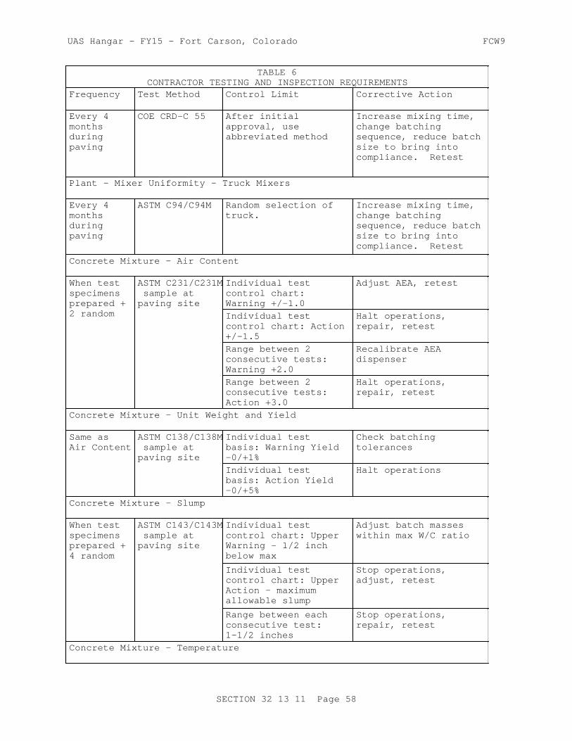
UAS Hangar - FY15 - Fort Carson, Colorado FCW9
TABLE 6CONTRACTOR TESTING AND INSPECTION REQUIREMENTS
Frequency Test Method Control Limit Corrective Action
Every 4 months during paving
COE CRD-C 55 After initial approval, use abbreviated method
Increase mixing time, change batching sequence, reduce batch size to bring into compliance. Retest
Plant - Mixer Uniformity - Truck Mixers
Every 4 months during paving
ASTM C94/C94M Random selection of truck.
Increase mixing time, change batching sequence, reduce batch size to bring into compliance. Retest
Concrete Mixture - Air Content
When test specimens prepared + 2 random
ASTM C231/C231M sample at paving site
Individual test control chart: Warning +/-1.0
Adjust AEA, retest
Individual test control chart: Action +/-1.5
Halt operations, repair, retest
Range between 2 consecutive tests: Warning +2.0
Recalibrate AEA dispenser
Range between 2 consecutive tests: Action +3.0
Halt operations, repair, retest
Concrete Mixture - Unit Weight and Yield
Same as Air Content
ASTM C138/C138M sample at paving site
Individual test basis: Warning Yield -0/+1%
Check batching tolerances
Individual test basis: Action Yield -0/+5%
Halt operations
Concrete Mixture - Slump
When test specimens prepared + 4 random
ASTM C143/C143M sample at paving site
Individual test control chart: Upper Warning - 1/2 inch below max
Adjust batch masses within max W/C ratio
Individual test control chart: Upper Action - maximum allowable slump
Stop operations, adjust, retest
Range between each consecutive test: 1-1/2 inches
Stop operations, repair, retest
Concrete Mixture - Temperature
SECTION 32 13 11 Page 58

UAS Hangar - FY15 - Fort Carson, Colorado FCW9
TABLE 6CONTRACTOR TESTING AND INSPECTION REQUIREMENTS
Frequency Test Method Control Limit Corrective Action
When test specimens prepared
ASTM C1064/C106 sample at paving site
See paragraph WEATHER LIMITATIONS
Concrete Mixture - Strength
8 per lot ASTM C31/C31M sample at paving station
See paragraph CONCRETE STRENGTH TESTING for CQC
Paving - Inspection Before Paving
Prior to each paving operation
Report Inspect underlying materials, construction joint faces, forms, reinforcing, dowels, and embedded items
Paving - Inspection During Paving
During paving operation
Monitor and control paving operation,including placement, consolidation,finishing, texturing, curing, and joint sawing.
Paving - Vibrators
Weekly during paving
COE CRD-C 521 Test frequency (in concrete), and amplitude (in air), measure at tip/head and average.
Repair or replace defective vibrators.
Moist Curing
2 per lot, min 4 per day
Visual Repair defects, extend curing by 1 day
Membrane Compound Curing
Daily Visual Calculate coverage based on quantity/area
Respray areas where coverage defective. Recalibrate equipment
Cold Weather Protection
Once per day
Visual Repair defects, report conditions to COR
SECTION 32 13 11 Page 59

UAS Hangar - FY15 - Fort Carson, Colorado FCW9
3.12.3 Concrete Strength Testing for Contractor CQC
Contractor Quality Control operations for concrete strength shall consist of the following steps:
a. Take samples for strength tests at the paving site. Fabricate and cure test beams in accordance with ASTM C31/C31M; test them in accordance with ASTM C78/C78M.
b. Fabricate and cure 2 test beams per sublot from the same batch or
truckload and at the same time acceptance beams are fabricated and test them for flexural strength at 7-day age.
c. Average all 8 flexural tests per lot. Convert this average 7-day flexural strength per lot to equivalent 90-day flexural strength using the Correlation Ratio determined during mixture proportioning studies.
d. Compare the equivalent 90-day flexural strength from the conversion to the Average Flexural Strength Required for Mixtures from paragraph of same title.
e. If the equivalent average 90-day strength for the lot is below the Average Flexural Strength Required for Mixtures by 69 psi flexural strength or more, at any time, adjust the mixture to increase the strength, as approved.
f. The Contractor's CQC testing agency shall maintain up-to-date control charts for strength, showing the 7-day CQC flexural strength and the 90-day flexural strength (from acceptance tests) of each of these for each lot.
3.12.4 Reports
All results of tests or inspections conducted shall be reported informally as they are completed and in writing daily. Prepare a weekly report for the updating of control charts covering the entire period from the start of the construction season through the current week. During periods of cold-weather protection, make daily reports of pertinent temperatures. These requirements do not relieve the Contractor of the obligation to report certain failures immediately as required in preceding paragraphs. Such reports of failures and the action taken shall be confirmed in writing in the routine reports. The Contracting Officer has the right to examine all Contractor quality control records.
-- End of Section --
SECTION 32 13 11 Page 60

UAS Hangar - FY15 - Fort Carson, Colorado FCW9
SECTION TABLE OF CONTENTS
DIVISION 32 - EXTERIOR IMPROVEMENTS
SECTION 32 13 11.10
CONCRETE PAVEMENT FOR AIRFIELD HANGAR FLOORS
05/15/2014
PART 1 GENERAL
1.1 Hangar Floor 1.2 Hangar Floor Finish 1.3 Radiant Tubing 1.4 Under Slab Insulation 1.5 Capillary Barrier and Engineered Fill 1.6 UNIT PRICES 1.6.1 Measurements 1.6.2 Payments 1.6.2.1 Lump Sum 1.6.3 Payment of Lots 1.6.4 Payment Adjustment for Smoothness 1.6.5 Payment Adjustment for Plan Grade 1.7 REFERENCES 1.8 SYSTEM DESCRIPTION 1.8.1 Surface Smoothness 1.8.2 Plan Grade 1.8.3 Flexural Strength 1.8.4 Thickness 1.8.5 Diamond Grinding of PCC Surfaces 1.9 SUBMITTALS 1.10 QUALITY CONTROL 1.10.1 Contractor Quality Control Staff 1.10.2 Other Staff 1.10.3 Laboratory Accreditation and Validation 1.10.4 1.4.6 Pre-Installation Conference 1.10.5 Preconstruction Testing of Materials 1.10.5.1 Aggregates 1.10.5.2 Chemical Admixtures, Curing Compounds and Epoxies 1.10.5.3 Cementitious Materials 1.10.6 Testing During Construction 1.10.7 Test Section 1.10.7.1 Pilot Lane 1.10.7.2 Fill-In Lane 1.10.8 Acceptability of Work 1.10.9 Acceptance Requirements 1.10.9.1 Floor Lots 1.10.9.2 Evaluation 1.11 DELIVERY, STORAGE, AND HANDLING 1.11.1 Bulk Cementitious Materials 1.11.2 Aggregate Materials 1.11.3 Other Materials
PART 2 PRODUCTS
SECTION 32 13 11.10 Page 1

UAS Hangar - FY15 - Fort Carson, Colorado FCW9
2.1 CEMENTITIOUS MATERIALS 2.1.1 Portland Cement 2.1.2 Blended Cements 2.1.3 Pozzolan 2.1.3.1 Fly Ash 2.1.3.2 Raw or Calcined Natural Pozzolan 2.1.3.3 Ultra Fine Fly Ash and Ultra Fine Pozzolan 2.1.4 Ground Granulated Blast-Furnace (GGBF) Slag 2.1.5 Supplementary Cementitious Materials (SCM) Content 2.2 AGGREGATES 2.2.1 Aggregate Sources 2.2.1.1 Durability 2.2.1.2 Alkali-Silica Reactivity 2.2.1.3 Combined Aggregate Gradation 2.2.2 Coarse Aggregate 2.2.2.1 Material Composition 2.2.2.2 Particle Shape Characteristics 2.2.2.3 Size and Grading 2.2.2.4 Deleterious Materials - Airfield Pavements 2.2.2.5 Testing Sequence/Deleterious Materials in Coarse Aggregate
- Airfield Hangar Floors 2.2.3 Fine Aggregate 2.2.3.1 Composition 2.2.3.2 Grading 2.2.3.3 Deleterious Material 2.3 CHEMICAL ADMIXTURES 2.3.1 General Requirements 2.3.2 Lithium Nitrate 2.4 MEMBRANE FORMING CURING COMPOUND 2.5 WATER 2.6 JOINT MATERIALS 2.7 REINFORCING 2.7.1 Reinforcing Bars and Bar Mats 2.7.2 Welded Wire Reinforcement 2.8 DOWELS 2.8.1 Dowels 2.8.2 Dowel Bar Assemblies 2.9 EPOXY RESIN 2.10 EQUIPMENT 2.10.1 Batching and Mixing Plant 2.10.2 Concrete Mixers 2.10.3 Transporting Equipment 2.10.4 Transfer and Spreading Equipment 2.10.5 Paver-Finisher 2.10.6 Curing Equipment 2.10.7 Sawing Equipment 2.10.8 Straightedge 2.10.9 Work Bridge 2.11 SPECIFIED CONCRETE STRENGTH AND OTHER PROPERTIES 2.11.1 Specified Flexural Strength 2.11.2 Water-Cementitious Materials Ratio 2.11.3 Air Content 2.11.4 Slump 2.11.5 Concrete Temperature 2.11.6 Concrete Strength for Final Acceptance 2.12 MIXTURE PROPORTIONS 2.12.1 Composition 2.12.2 Proportioning Studies 2.12.2.1 Water-Cementitious Materials Ratio
SECTION 32 13 11.10 Page 2

UAS Hangar - FY15 - Fort Carson, Colorado FCW9
2.12.2.2 Trial Mixture Studies 2.12.2.3 Mixture Proportioning for Flexural Strength 2.12.3 Average CQC Flexural Strength Required for Mixtures
PART 3 EXECUTION
3.1 PREPARATION FOR PAVING 3.1.1 Weather Precaution 3.1.2 Proposed Techniques 3.2 CONDITIONING OF UNDERLYING MATERIAL 3.2.1 General Procedures 3.2.2 Insulation 3.2.3 Radiant Slab Heating Sytem 3.2.4 Traffic on Underlying Material 3.3 WEATHER LIMITATIONS 3.3.1 Placement and Protection During Inclement Weather 3.3.2 Paving in Hot Weather 3.3.3 Prevention of Plastic Shrinkage Cracking 3.3.4 Paving in Cold Weather 3.4 CONCRETE PRODUCTION 3.4.1 Batching and Mixing Concrete 3.4.2 Transporting and Transfer - Spreading Operations 3.5 PAVING 3.5.1 General Requirements 3.5.2 Consolidation 3.5.3 Operation 3.5.4 Required Results 3.5.5 Fixed Form Paving 3.5.5.1 Forms for Fixed-Form Paving 3.5.5.2 Form Removal 3.5.6 Placing Reinforcing Steel 3.5.6.1 Pavement Thickness Less Than 12 Inches 3.5.7 Placing Dowels 3.5.7.1 Contraction Joints 3.5.7.2 Construction Joints-Dowels Installed in Fresh Concrete 3.5.7.3 Dowels Installed in Hardened Concrete 3.5.7.4 Lubricating Dowel Bars 3.6 FINISHING 3.6.1 Machine Finishing With Fixed Forms 3.6.2 Surface Correction and Testing 3.6.3 Hand Finishing 3.6.3.1 Equipment and Template 3.6.3.2 Finishing and Floating 3.6.4 In-Floor Items 3.7 CURING 3.7.1 Protection of Concrete 3.7.2 Membrane Curing 3.8 JOINTS 3.8.1 General Requirements for Joints 3.8.2 Longitudinal Construction Joints 3.8.3 Transverse Construction Joints 3.8.4 Isolation Joints 3.8.5 Slip Joints 3.8.6 Contraction Joints 3.8.7 Thickened Edge Joints 3.9 REPAIR, REMOVAL AND REPLACEMENT OF NEWLY CONSTRUCTED SLABS 3.9.1 General Criteria 3.9.2 Slabs with Cracks 3.9.3 Removal and Replacement of Full Slabs
SECTION 32 13 11.10 Page 3
UAS Hangar - FY15 - Fort Carson, Colorado FCW9
3.9.4 Repairing Spalls Along Joints 3.9.5 Repair of Weak Surfaces 3.10 FLOOR PROTECTION 3.11 TESTING AND INSPECTION FOR CONTRACTOR QUALITY CONTROL 3.11.1 Testing and Inspection by Contractor 3.11.2 Testing and Inspection Requirements 3.11.3 Concrete Strength Testing for Contractor CQC 3.11.4 Reports
-- End of Section Table of Contents --
SECTION 32 13 11.10 Page 4

UAS Hangar - FY15 - Fort Carson, Colorado FCW9
SECTION 32 13 11.10
CONCRETE PAVEMENT FOR AIRFIELD HANGAR FLOORS05/15/2014
PART 1 GENERAL
1.1 Hangar Floor
This specification covers the concrete requirements for the hangar floor in the project hangar bay areas only. See 03 30 00.00 10 CAST-IN-PLACE STRUCTURAL CONCRETE for requirements for other concrete and floor requirements in the areas.
1.2 Hangar Floor Finish
Requirements for the ground and polished concrete finish are covered in 03 35 00.00 10 CONCRETE FINISHING.
1.3 Radiant Tubing
Requirements for the radiant slab tubing and associated heating system can be found in 23 52 00 RADIANT SLAB HEATING SYSTEM.
1.4 Under Slab Insulation
Requirements for under slab insulation as identified in the design drawings, can be found in 07 21 13 BOARD AND BLOCK INSULATION.
1.5 Capillary Barrier and Engineered Fill
Requirements for the slab capillary barrier and engineered fill as identified in the design drawings, can be found in 31 00 00 EARTHWORK.
1.6 UNIT PRICES
1.6.1 Measurements
The quantity of concrete to be paid for will be the volume of concrete in cubic yards including thickened edges , where required, placed in the completed and accepted pavement. Concrete will be measured in place in the completed and accepted pavement only within the neat line dimensions shown in the plan and cross section. No deductions will be made for rounded or beveled edges or the space occupied by pavement reinforcement, dowel bars,or electrical conduits, nor for any void, or other structure extending into or through the pavement slab, measuring 3 cubic feet or less in volume. No other allowance for concrete will be made unless placed in specified locations in accordance with written instructions previously issued by the Contracting Officer. The quantity of other materials specified herein, and used in the construction of the work covered by this section, will not be measured for payment, but will be considered a subsidiary obligation of the Contractor, covered under the price per cubic yard for concrete.
SECTION 32 13 11.10 Page 5
UAS Hangar - FY15 - Fort Carson, Colorado FCW9
1.6.2 Payments
1.6.2.1 Lump Sum
The quantity of concrete will be paid for and included in the lump-sum contract price. If less than 100 percent payment is due based on the pay factors stipulated below, a unit price of $285 per cubic yard will be used for purposes of calculating the payment reduction.
1.6.3 Payment of Lots
When a lot of material fails to meet the specification requirements, that lot will be accepted at a reduced price or shall be removed and replaced. The lowest computed percent payment determined for any pavement characteristic (i.e., grade, and surface smoothness) discussed below shall be the actual percent payment for that lot. The actual percent payment will be applied to the unit price and the measured quantity of concrete in the lot to determine actual payment. Use results of strength tests to control concreting operations. Strength will be evaluated, but will not be considered for payment adjustment. Any pavement not meeting the required 'specified strength' shall be removed and replaced at no additional cost to the Government.
1.6.4 Payment Adjustment for Smoothness
a. Straightedge Testing: Location and deviation from straightedge for all measurements shall be recorded. When more than 5.0 and less than or equal to 10.0 percent of all measurements made within a lot exceed the tolerance specified in paragraph "Surface Smoothness", after any reduction of high spots or removal and replacement, the computed percent payment based on surface smoothness will be 95 percent. When more than 10.0 percent and less than or equal to 15.0 percent of all measurements exceed the tolerance, the computed percent payment will be 90 percent. When more than 15.0 and less than or equal to 20.0 percent of all measurements exceed the tolerance, the computed percent payment will be 75 percent. When more than 20.0 percent of the measurements exceed the tolerance, the lot shall be removed and replaced at no additional cost to the Government.
1.6.5 Payment Adjustment for Plan Grade
When more than 5.0 and less than or equal to 10.0 percent of all measurements made within a lot are outside the specified tolerance, the computed percent payment for that lot will be 95 percent. When more than 10.0 percent but less than 50 percent are outside the specified tolerances, the computed percent payment for the lot will be 75 percent. In any areas where the deviation from grade exceeds the specified tolerances by 50 percent or more, the deficient area shall be removed and replaced at no additional cost to the Government.
1.7 REFERENCES
The publications listed below form a part of this specification to the extent referenced. The publications are referred to within the text by the basic designation only.
ACI INTERNATIONAL (ACI)
ACI 309R (2005) Guide for Consolidation of Concrete
SECTION 32 13 11.10 Page 6

UAS Hangar - FY15 - Fort Carson, Colorado FCW9
AMERICAN ASSOCIATION OF STATE HIGHWAY AND TRANSPORTATION OFFICIALS (AASHTO)
AASHTO M 182 (2005; R 2009) Standard Specification for Burlap Cloth Made from Jute or Kenaf and Cotton Mats
AMERICAN CONCRETE INSTITUTE INTERNATIONAL (ACI)
ACI 211.1 (1991; R 2009) Standard Practice for Selecting Proportions for Normal, Heavyweight and Mass Concrete
ACI 214R (2011) Evaluation of Strength Test Results of Concrete
ACI 305R (2010) Guide to Hot Weather Concreting
ACI 306R (2010) Guide to Cold Weather Concreting
ASTM INTERNATIONAL (ASTM)
ASTM A184/A184M (2006; E2011) Standard Specification for Fabricated Deformed Steel Bar Mats for Concrete Reinforcement
ASTM A185/A185M (2007) Standard Specification for Steel Welded Wire Reinforcement, Plain, for Concrete
ASTM A497/A497M (2007) Standard Specification for Steel Welded Wire Reinforcement, Deformed, for Concrete
ASTM A615/A615M (2013) Standard Specification for Deformed and Plain Carbon-Steel Bars for Concrete Reinforcement
ASTM A775/A775M (2007b) Standard Specification for Epoxy-Coated Steel Reinforcing Bars
ASTM A996/A996M (2009b) Standard Specification for Rail-Steel and Axle-Steel Deformed Bars for Concrete Reinforcement
ASTM C 856 (2004) Petrographic Examination of Hardened Concrete
ASTM C1064/C1064M (2011) Standard Test Method for Temperature of Freshly Mixed Hydraulic-Cement Concrete
ASTM C1077 (2014) Standard Practice for Laboratories Testing Concrete and Concrete Aggregates for Use in Construction and Criteria for Laboratory Evaluation
ASTM C117 (2013) Standard Test Method for Materials
SECTION 32 13 11.10 Page 7
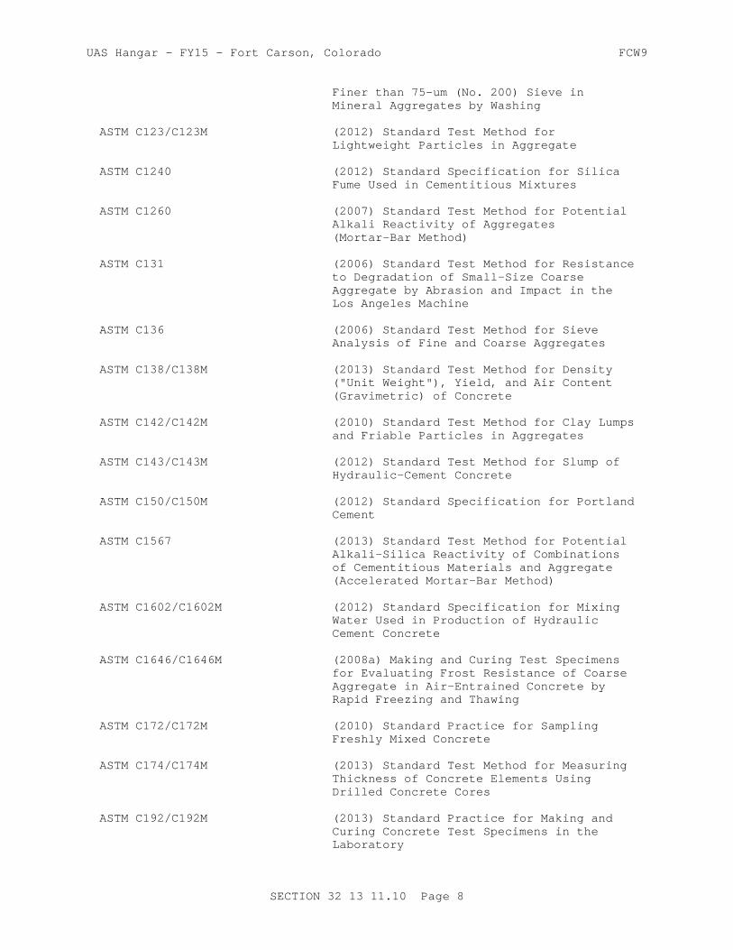
UAS Hangar - FY15 - Fort Carson, Colorado FCW9
Finer than 75-um (No. 200) Sieve in Mineral Aggregates by Washing
ASTM C123/C123M (2012) Standard Test Method for Lightweight Particles in Aggregate
ASTM C1240 (2012) Standard Specification for Silica Fume Used in Cementitious Mixtures
ASTM C1260 (2007) Standard Test Method for Potential Alkali Reactivity of Aggregates (Mortar-Bar Method)
ASTM C131 (2006) Standard Test Method for Resistance to Degradation of Small-Size Coarse Aggregate by Abrasion and Impact in the Los Angeles Machine
ASTM C136 (2006) Standard Test Method for Sieve Analysis of Fine and Coarse Aggregates
ASTM C138/C138M (2013) Standard Test Method for Density ("Unit Weight"), Yield, and Air Content (Gravimetric) of Concrete
ASTM C142/C142M (2010) Standard Test Method for Clay Lumps and Friable Particles in Aggregates
ASTM C143/C143M (2012) Standard Test Method for Slump of Hydraulic-Cement Concrete
ASTM C150/C150M (2012) Standard Specification for Portland Cement
ASTM C1567 (2013) Standard Test Method for Potential Alkali-Silica Reactivity of Combinations of Cementitious Materials and Aggregate (Accelerated Mortar-Bar Method)
ASTM C1602/C1602M (2012) Standard Specification for Mixing Water Used in Production of Hydraulic Cement Concrete
ASTM C1646/C1646M (2008a) Making and Curing Test Specimens for Evaluating Frost Resistance of Coarse Aggregate in Air-Entrained Concrete by Rapid Freezing and Thawing
ASTM C172/C172M (2010) Standard Practice for Sampling Freshly Mixed Concrete
ASTM C174/C174M (2013) Standard Test Method for Measuring Thickness of Concrete Elements Using Drilled Concrete Cores
ASTM C192/C192M (2013) Standard Practice for Making and Curing Concrete Test Specimens in the Laboratory
SECTION 32 13 11.10 Page 8

UAS Hangar - FY15 - Fort Carson, Colorado FCW9
ASTM C231/C231M (2010) Standard Test Method for Air Content of Freshly Mixed Concrete by the Pressure Method
ASTM C260/C260M (2010a) Standard Specification for Air-Entraining Admixtures for Concrete
ASTM C29/C29M (2009) Standard Test Method for Bulk Density ("Unit Weight") and Voids in Aggregate
ASTM C294 (2012) Standard Descriptive Nomenclature for Constituents of Concrete Aggregates
ASTM C295/C295M (2012) Petrographic Examination of Aggregates for Concrete
ASTM C309 (2011) Standard Specification for Liquid Membrane-Forming Compounds for Curing Concrete
ASTM C31/C31M (2012) Standard Practice for Making and Curing Concrete Test Specimens in the Field
ASTM C33/C33M (2013) Standard Specification for Concrete Aggregates
ASTM C39/C39M (2014) Standard Test Method for Compressive Strength of Cylindrical Concrete Specimens
ASTM C494/C494M (2013) Standard Specification for Chemical Admixtures for Concrete
ASTM C595/C595M (2013) Standard Specification for Blended Hydraulic Cements
ASTM C618 (2012a) Standard Specification for Coal Fly Ash and Raw or Calcined Natural Pozzolan for Use in Concrete
ASTM C666/C666M (2003; R 2008) Resistance of Concrete to Rapid Freezing and Thawing
ASTM C78/C78M (2012; E 2013) Standard Test Method for Flexural Strength of Concrete (Using Simple Beam with Third-Point Loading)
ASTM C88 (2013) Standard Test Method for Soundness of Aggregates by Use of Sodium Sulfate or Magnesium Sulfate
ASTM C881/C881M (2010) Standard Specification for Epoxy-Resin-Base Bonding Systems for Concrete
ASTM C94/C94M (2014) Standard Specification for Ready-Mixed Concrete
SECTION 32 13 11.10 Page 9

UAS Hangar - FY15 - Fort Carson, Colorado FCW9
ASTM C989/C989M (2013) Standard Specification for Slag Cement for Use in Concrete and Mortars
ASTM D1751 (2004; R 2008) Standard Specification for Preformed Expansion Joint Filler for Concrete Paving and Structural Construction (Nonextruding and Resilient Bituminous Types)
ASTM D1752 (2004a; R 2008) Standard Specification for Preformed Sponge Rubber Cork and Recycled PVC Expansion
ASTM D2995 (1999; R 2009) Determining Application Rate of Bituminous Distributors
ASTM D3665 (2012) Random Sampling of Construction Materials
ASTM D4791 (2010) Flat Particles, Elongated Particles, or Flat and Elongated Particles in Coarse Aggregate
ASTM D75/D75M (2013) Standard Practice for Sampling Aggregates
ASTM E1155 (1996; R 2008) Standard Test Method for Determining Floor Flatness and Floor Levelness Numbers
ASTM E1274 (2003; R 2012) Standard Test Method for Measuring Pavement Roughness Using a Profilograph
NATIONAL READY MIXED CONCRETE ASSOCIATION (NRMCA)
NRMCA QC 3 (2011) Quality Control Manual: Section 3, Plant Certifications Checklist: Certification of Ready Mixed Concrete Production Facilities
U.S. ARMY CORPS OF ENGINEERS (USACE)
COE CRD-C 130 (2001) Standard Recommended Practice for Estimating Scratch Hardness of Coarse Aggregate Particles
COE CRD-C 143 (1962) Specifications for Meters for Automatic Indication of Moisture in Fine Aggregate
COE CRD-C 300 (1990) Specifications for Membrane-Forming Compounds for Curing Concrete
COE CRD-C 521 (1981) Standard Test Method for Frequency and Amplitude of Vibrators for Concrete
COE CRD-C 55 (1992) Test Method for Within-Batch Uniformity of Freshly Mixed Concrete
SECTION 32 13 11.10 Page 10

UAS Hangar - FY15 - Fort Carson, Colorado FCW9
COE CRD-C 662 (2009) Determining the Potential Alkali-Silica Reactivity of Combinations of Cementitious Materials, Lithium Nitrate Admixture and Aggregate (Accelerated Mortar-Bar Method)
1.8 SYSTEM DESCRIPTION
This section is intended to for construction of portland cement concrete hangar floor slabs in the interior of the hangar. However, where the construction covered herein interfaces with other sections, the construction at each interface shall conform to the requirements of both this section and the other section, including tolerances for both.
1.8.1 Surface Smoothness
Provide Flatness Factor level as identified in 03 35 00.00 10 CONCRETE FINISHING under paragraph labeled "Floor Slabs with Ground and Polish Finish"
1.8.2 Plan Grade
Within 5 days after paving of each lot, the finished surface of the pavement area shall be tested, by running lines of levels at intervals corresponding with every longitudinal and transverse joint to determine the elevation at each joint intersection in accordance with ASTM E1155. The results of this survey shall be recorded and a copy given to the Government at the completion of the survey of each lot. The finished surface of hangar pavement shall vary not more than 1/8 inch above or below the plan grade line or elevation indicated. The above deviations from the approved grade line and elevation will not be permitted in areas where closer conformance with the planned grade and elevation is required for the proper functioning of appurtenant structures. The finished surfaces of new abutting pavements shall coincide at their juncture.
1.8.3 Flexural Strength
Submit certified copies of laboratory test reports and sources for cement, supplementary cementitious materials (SCM), aggregates, admixtures, curing compound, epoxy, and proprietary patching materials proposed for use on this project. All aggregate tests shall have been performed no earlier than 6 months prior to contract award. Each lot of pavement will be evaluated for acceptance in accordance with the following procedures.
a. Sampling and Testing: For acceptance, one composite sample of concrete from each sublot shall be obtained in accordance with ASTM C172/C172M from one batch or truckload.
b. Computations: Average the eight 14-day strength tests for the lot. The average strength shall be used in accordance with paragraph "Concrete Strength for Final Acceptance" in PART 2.
1.8.4 Thickness
No coring for thickness testing of the hangar floor slab shall be performed.
SECTION 32 13 11.10 Page 11

UAS Hangar - FY15 - Fort Carson, Colorado FCW9
1.8.5 Diamond Grinding of PCC Surfaces
In areas not meeting the specified limits for surface smoothness and plan grade, high areas shall be reduced to attain the required smoothness and grade, except as depth is limited below. High areas shall be reduced by grinding the hardened concrete with an approved diamond grinding machine after the concrete is at a minimum age of 14 days. Grinding shall be accomplished by grinding with an industrial diamond abrasive disks. The disk(s) shall be assembled on a machine designed specifically for diamond grinding that will produce the required texture and smoothness level without damage to the concrete pavement or joint faces and shall be approved by the contracting officer. Grinding equipment that causes ravels, aggregate fractures, spalls or disturbance to the joints will not be permitted. The area corrected by grinding the surface of the hardened concrete shall not exceed 10 percent of the total area of any sublot. The depth of diamond grinding shall not exceed 1/4 inch. All pavement areas requiring plan grade or surface smoothness corrections in excess of the limits specified above, shall be removed and replaced in conformance with paragraph REPAIR, REMOVAL, AND REPLACEMENT OF NEWLY CONSTRUCTED SLABS.
1.9 SUBMITTALS
Government approval is required for submittals with a "G" designation; submittals not having a "G" designation are for . information only. When used, a designation following the "G" designation identifies the office that will review the submittal for the Government. Submit the following in accordance with Section 01 33 00 SUBMITTAL PROCEDURES:
SD-03 Product Data
EquipmentProposed Techniques; G, DODowels; G, PODowel Bar Assemblies; G, PO
SD-05 Design Data
Proportioning Studies; G, DO
SD-06 Test Reports
Sampling and Testing; G, DO
SD-07 Certificates
Contractor Quality Control Staff; G, DOLaboratory Accreditation; G, DONRMCA Certificate of Conformance; G, DO
1.10 QUALITY CONTROL
1.10.1 Contractor Quality Control Staff
Submit American Concrete Institute certification for Contractor Quality Control staff. Qualifications and resumes for petrographer, surveyor, concrete batch plant operator, and profilograph operator. All Contractor Quality Control personnel assigned to concrete construction shall be American Concrete Institute (ACI) certified in the following grade (or shall have written evidence acceptable to the Contracting Officer's
SECTION 32 13 11.10 Page 12

UAS Hangar - FY15 - Fort Carson, Colorado FCW9
representative of having completed similar qualification programs):
a. CQC personnel responsible for inspection of concrete paving operations: ACI Concrete Transportation Inspector.
b. Lead Foreman or Journeyman of the Concrete Placing, Finishing, and Curing Crews: ACI Concrete Flatwork Technician/Finisher.
c. Field Testing Technicians: ACI Concrete Field Testing Technician, Grade I.
d. Laboratory Testing Technicians: ACI Concrete Strength Testing Technician and Laboratory Testing Technician, Grade I or II.
1.10.2 Other Staff
Submit for approval, the qualifications and resumes for the following staff:
a. Flatness Surveyor: Demonstrate minimum of one year prior experience in using apparatus to determine flatness level.
b. Concrete Batch Plant Operator: National Ready Mix Concrete Association (NRMCA) Plant Manager certification at the Plant Operator level.
1.10.3 Laboratory Accreditation and Validation
Laboratory and testing facilities shall be provided by and at the expense of the Contractor. Submit accreditation of the commercial laboratory by an independent evaluation authority, indicating conformance to ASTM C1077, including all applicable test procedures. The laboratories performing the tests shall be accredited in accordance with ASTM C1077, including ASTM C78/C78M and ASTM C1260. The accreditation shall be current and shall include the required and optional test methods, as specified throughout this Section. In addition, all contractor quality control testing laboratories performing acceptance testing shall require USACE validation by the Material Testing Center (MTC)for both parent laboratory and on-site laboroatory. Validation on all laboratories must remain current throughout the duration of the paving project. Contact the MTC manager at http://gsl.erdc.usace.army.mil/SL/MTC/ for costs and scheduling. Onsite temperature-controlled concrete curing facilities shall be provided.
a. Aggregate Testing and Mix Proportioning: Aggregate testing and mixture proportioning studies shall be performed by a commercial laboratory.
b. Acceptance Testing: Furnish all materials, labor, and facilities required for molding, curing, testing, and protecting test specimens at the site and in the laboratory. Steel molds shall be used for molding the beam specimens. Furnish and maintain boxes or other facilities suitable for storing and curing the specimens at the site while in the mold within the temperature range stipulated by ASTM C31/C31M. Flexural loading equipment shall be in accordance with ASTM C78/C78M.
c. Contractor Quality Control: All sampling and testing shall be performed by an approved, onsite, independent, commercial laboratory, or for cementitious materials and admixtures, the manufacturer's laboratory.
d. Laboratory Inspection: The Government will inspect those laboratories requiring validation for equipment and test procedures prior to the
SECTION 32 13 11.10 Page 13

UAS Hangar - FY15 - Fort Carson, Colorado FCW9
start of any concreting operations for conformance to ASTM C1077. Scheduling and costs for laboratory inspections shall be borne by the contractor. The Contractor will not be entitled to any additional payment or extension of time due to failure to acquire the required laboratory validation.
1.10.4 1.4.6 Pre-Installation Conference
Prior to the installation of the hangar floor slab system, an on-site conference shall be conducted by the General Contractor, Product Manufacturers and Installers for items such as radiant slab heating system, ground and polished finish, etc., and government representative to review specification requirements. Minimum agenda shall include the following:
a. Tour of work area, inspection and discussion of preparation of substrate and other pre-installation conditions and issues.
b. Review of system requirements, including drawings, specifications and other contract documents. Review shall include review of surface finish characteristics to achieve a ground and polished finish and means and methods of installing radiant slab heating system in order to avoid damage during placement of concrete. Review method of creating control joints as indicated on the plans.
c. Review of required submittals and completion status.
d. Review and finalization of installation schedule, and verification of availability of required materials, trained Installer personnel, equipment and facilities to execute specification and avoid delays.
e. Limit access to work area by other trades to reduce possible damage to the floor before, during and after completion.
f. Review of required inspection, testing, certification and material usage accounting procedures.
g. Review of power requirements and responsibility.
h. Review of governing regulations and requirements for insurance,certifications, inspection and testing, if applicable.
i. Review of temporary protection requirements during and after installation.
j. Review of cleaning procedures during and after installation.
k. Review of installation requirements for floor finish, radiant heat tubing, under slab rigid insulation, rebar, dowels and items embedded in the slab.
1.10.5 Preconstruction Testing of Materials
All sampling and testing shall be performed by, and at the expense of, the Contractor. Use an approved commercial laboratory or, for cementitious materials and chemical admixtures, a laboratory maintained by the manufacturer of the material. No material shall be used until notice of acceptance has been given. The Contractor will not be entitled to any additional payment or extension of time due to failure of any material to meet project requirements, or for any additional sampling or testing
SECTION 32 13 11.10 Page 14

UAS Hangar - FY15 - Fort Carson, Colorado FCW9
required. Additional tests may be performed by the Government at the discretion of the Contracting Officer; such Government testing will not relieve the Contractor of any testing responsibilities.
1.10.5.1 Aggregates
Aggregates shall be sampled in the presence of a Government Representative. Samples shall be obtained in accordance with ASTM D75/D75M and shall be representative of the materials to be used for the project. Test results shall be submitted 7 days before commencing mixture proportioning studies.
1.10.5.2 Chemical Admixtures, Curing Compounds and Epoxies
At least 30 days before the material is used, submit certified copies of test results for the specific lots or batches to be used on the project. Test results shall be not more than 6 months old prior to use in the work. Chemical admixtures that have been in storage at the project site for longer than 6 months or that have been subjected to freezing will be retested at the expense of the Contractor and will be rejected if test results are not satisfactory.
1.10.5.3 Cementitious Materials
Cement, ground granulated blast furnace (GGBF) slag, and pozzolan will be accepted on the basis of manufacturer's certification of compliance, accompanied by mill test reports showing that the material in each shipment meets the requirements of the specification under which it is furnished. Mill test reports shall be no more than 1 month old, prior to use in the work. No cementitious material shall be used until notice of acceptance has been given by the Contracting Officer. Cementitious material may be subjected to testing by the Government from samples obtained at the mill, at transfer points, or at the project site. If tests prove that a cementitious material that has been delivered is unsatisfactory, it shall be promptly removed from the site of the work. Cementitious material that has not been used within 6 months after testing shall be retested at the Contractor's expense and shall be rejected if test results are not satisfactory.
1.10.6 Testing During Construction
During construction, the Contractor is responsible for sampling and testing aggregates, cementitious materials, and concrete as specified herein. The Government will sample and test concrete and ingredient materials as considered appropriate. Provide facilities and labor as may be necessary for procurement of representative test samples. Testing by the Government will in no way relieve the Contractor of the specified testing requirements.
1.10.7 Test Section
Up to 10 working days, but not more than 20 working days, prior to construction of the concrete hangar floor, construct a test section on the job site and near the hangar structure, but not as part of the production hangar floor area when using radiant floor heating system. A test section at least 25 feet by 45 feet using the thickness as shown on the drawings for the hangar floor slab. Each slab shall have a full width transverse joint constructed and longitudinal construction joints spaced as shown on the drawings. Use the test section to develop and demonstrate compliance
SECTION 32 13 11.10 Page 15

UAS Hangar - FY15 - Fort Carson, Colorado FCW9
to all requiremnts herein and to the satisfaction of the Contracting Officerthe following items as a minimum:
1. Installation of items to be installed below the finish concrete surface such as base course, insulation, and radiant tubing.2. The proposed techniques of mixing, hauling, placing, consolidating, finishing, and curing of the concrete3. A doweled longitudinal consturction joint shall be installed full length along one side of the test section.4. Initial saw cutting5. Concrete and floor surface testing methods6. Concrete plant operations7. Preparation of at least one contraction joint and one construction joint.8. Application of the ground and polish finish system as specified in 03 35 00.00 10 CONCRETE FINISHING
Variations in mixture proportion, other than increasing the approved water/cementitious materials ratio, shall be made if directed. The panel shall be constructed on a grade (base course) similar to that specified for the hangar floor.
The concrete mixing plant shall be operated and calibrated prior to start of placing the test section. Use the same equipment, materials, and construction techniques on the test section as will be used in all subsequent work.
Base course preparation, concrete production, placing, consolidating, curing, construction of joints, and all testing shall be in accordance with applicable provisions of this specification.
Mock up shall be poured at the same slope (elevations) as the actual hangar floor
The floor concrete will be evaluated for aggregate distribution, consolidation and segregation using a minimum of eight cores from randomly selected locations or as directed by the Contracting Officer.
Failure to construct an acceptable test section will necessitate construction of additional cost to the Government. Test sections allowed to be constructed as part of the actual hangar floor construction which do not meet specification requirements shall not commence until the results on aggregates and concrete, including evaluation of the cores, and all floor measurements for actual plan grade, surface smoothness and thickness have been submitted and approved by the Contracting Officer. Floor areas accepted as part of the final hangar floor will be evaluated and paid in accordance the Paragraph: ACCEPTABILITY OF WORK.
1.10.7.1 Pilot Lane
The test section's pilot lane shall consist of one paving lane at least45feet long and shall be constructed to the same thickness as the thickest portion of hangar slab shown on the drawings. The paving lane width shall be the same as that shown on the drawings. The test section shall contain a minimum of two transverse construction joints spaced as shown on the drawings. If doweled longitudinal construction joints are required in any of the production pavements, they shall be installed full length at midpoint along one side of the test section.
SECTION 32 13 11.10 Page 16

UAS Hangar - FY15 - Fort Carson, Colorado FCW9
Two separate days shall be used for construction of the test section's pilot and fill-in lanes.
1.10.7.2 Fill-In Lane
The first45 feet of the initial full production fill-in lane shall be considered the fill-in lane test section for purposes of testing and evaluation. All requirements for the fill-in test section are applicable, as appropriate.
1.10.8 Acceptability of Work
The materials and the pavement itself will be accepted on the basis of tests made by the Contractor. The Government may make check tests to validate the results of the Contractor's testing. If the results of the Contractor tests vary by less than 2.0 percent of the Government's test results, the results of the Contractor's tests will be used. If the results of the Government and Contractor tests vary by 2.0 percent, but less than 4.0 percent, the average of the two will be considered the value to be used. If these vary by 4.0 percent or more, each sampling and testing procedure shall be carefully evaluated and both the Government and the Contractor shall take another series of tests on duplicate samples of material. If these vary by 4.0 percent or more, the results of the tests made by the Government shall be used and the Government will continue check testing of this item on a continuous basis until the two sets of tests agree within less than 4.0 percent on a regular basis. Testing performed by the Government will in no way at any time relieve the Contractor from the specified testing requirements.
1.10.9 Acceptance Requirements
1.10.9.1 Floor Lots
A lot will be that quantity of construction that will be evaluated for acceptance with specification requirements. A lot will be equal to one shift of production not to exceed 1000cubic yards and will consist of four equal sublots. Grade determinations will be made on the lot as a whole. Surface smoothness determinations will be made on each lot. Location of all samples shall be selected on a random basis in accordance with ASTM D3665. When operational conditions cause a lot to be terminated before the specified four sublots have been completed, the following procedure shall be used to adjust the lot size and number of tests for the lot. Where three sublots have been completed, they shall constitute a lot. Where one or two sublots have been completed, they shall be incorporated into the next lot (except for the last lot), and the total number of sublots shall be used and acceptance criteria adjusted accordingly.
1.10.9.2 Evaluation
Provide all sampling and testing required for acceptance and payment adjustment at the Contractor's expense. Individuals performing sampling, testing and inspection duties shall meet the required Qualifications. The Contracting Officer reserves the right to direct additional samples and tests for any area which appears to deviate from the specification requirements. Testing in these areas will be in addition to the sublot or lot testing, and the requirements for these areas will be the same as those for a sublot or lot. Provide facilities for and, where directed, personnel to assist in obtaining samples for any Government testing.
SECTION 32 13 11.10 Page 17

UAS Hangar - FY15 - Fort Carson, Colorado FCW9
1.11 DELIVERY, STORAGE, AND HANDLING
1.11.1 Bulk Cementitious Materials
Furnish all cementitious material in bulk. The temperature of the cementitious material, as delivered to storage at the site, shall not exceed 150 degrees F. Sufficient cementitious materials shall be in storage to sustain continuous operation of the concrete mixing plant while the pavement is being placed. Provide separate facilities to prevent any intermixing during unloading, transporting, storing, and handling of each type of cementitious material.
1.11.2 Aggregate Materials
Store aggregate at the site of the batching and mixing plant avoiding breakage, segregation, intermixing or contamination by foreign materials. Each size of aggregate from each source shall be stored separately in free-draining stockpiles. Aggregate stored on ground shall have a minimum 24 inch thick sacrificial layer left undisturbed. Fine aggregate and the smallest size coarse aggregate shall remain in free-draining storage for at least 24 hours immediately prior to use. Sufficient aggregate shall be maintained at the site at all times to permit continuous uninterrupted operation of the mixing plant at the time concrete pavement is being placed. Tracked equipment shall not be allowed on coarse aggregate stockpiles.
1.11.3 Other Materials
Store reinforcing bars and accessories above the ground on supports. All materials shall be stored avoiding contamination and deterioration.
PART 2 PRODUCTS
2.1 CEMENTITIOUS MATERIALS
Cementitious materials shall be portland cement, blended cement or only portland cement in combination with supplementary cementitious materials (SCM), and shall conform to appropriate specifications listed below. New submittals are required when the cementitious materials sources or types change.
2.1.1 Portland Cement
Provide portland cement conforming to ASTM C150/C150M, Type I or II, low alkali, including false set requirements.
2.1.2 Blended Cements
Blended cement shall conform to ASTM C595/C595M, Type IP or IS, including the optional requirement for mortar expansion and sulfate soundness. The pozzolan added to the Type IP blend shall be ASTM C618 Class F or Class N and shall be interground with the cement clinker. The manufacturer shall state in writing that the amount of pozzolan in the finished cement will not vary more than plus or minus 5 mass percent of the finished cement from lot to lot or within a lot. The percentage and type of mineral admixture used in the blend shall not change from that submitted for the aggregate evaluation and mixture proportioning. The requirements of Table 2 in paragraph SUPPLEMENTARY CEMENTITIOUS MATERIALS (SCM) CONTENT do not apply to the SCM content of blended cement.
SECTION 32 13 11.10 Page 18
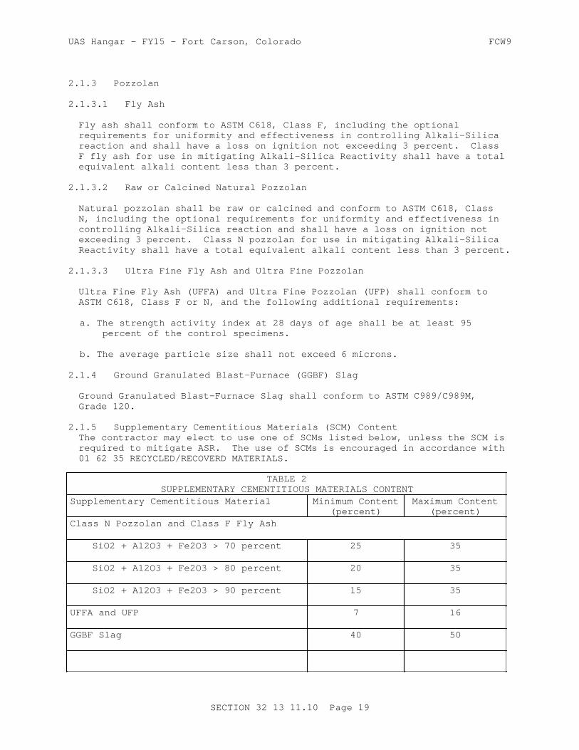
UAS Hangar - FY15 - Fort Carson, Colorado FCW9
2.1.3 Pozzolan
2.1.3.1 Fly Ash
Fly ash shall conform to ASTM C618, Class F, including the optional requirements for uniformity and effectiveness in controlling Alkali-Silica reaction and shall have a loss on ignition not exceeding 3 percent. Class F fly ash for use in mitigating Alkali-Silica Reactivity shall have a total equivalent alkali content less than 3 percent.
2.1.3.2 Raw or Calcined Natural Pozzolan
Natural pozzolan shall be raw or calcined and conform to ASTM C618, Class N, including the optional requirements for uniformity and effectiveness in controlling Alkali-Silica reaction and shall have a loss on ignition not exceeding 3 percent. Class N pozzolan for use in mitigating Alkali-Silica Reactivity shall have a total equivalent alkali content less than 3 percent.
2.1.3.3 Ultra Fine Fly Ash and Ultra Fine Pozzolan
Ultra Fine Fly Ash (UFFA) and Ultra Fine Pozzolan (UFP) shall conform to ASTM C618, Class F or N, and the following additional requirements:
a. The strength activity index at 28 days of age shall be at least 95 percent of the control specimens.
b. The average particle size shall not exceed 6 microns.
2.1.4 Ground Granulated Blast-Furnace (GGBF) Slag
Ground Granulated Blast-Furnace Slag shall conform to ASTM C989/C989M, Grade 120.
2.1.5 Supplementary Cementitious Materials (SCM) ContentThe contractor may elect to use one of SCMs listed below, unless the SCM is required to mitigate ASR. The use of SCMs is encouraged in accordance with 01 62 35 RECYCLED/RECOVERD MATERIALS.
TABLE 2SUPPLEMENTARY CEMENTITIOUS MATERIALS CONTENT
Supplementary Cementitious Material Minimum Content(percent)
Maximum Content(percent)
Class N Pozzolan and Class F Fly Ash
SiO2 + Al2O3 + Fe2O3 > 70 percent 25 35
SiO2 + A12O3 + Fe2O3 > 80 percent 20 35
SiO2 + A12O3 + Fe2O3 > 90 percent 15 35
UFFA and UFP 7 16
GGBF Slag 40 50
SECTION 32 13 11.10 Page 19
UAS Hangar - FY15 - Fort Carson, Colorado FCW9
2.2 AGGREGATES
2.2.1 Aggregate Sources
2.2.1.1 Durability
2.2.1.2 Alkali-Silica Reactivity
Fine and coarse aggregates to be used in all concrete shall be evaluated and tested for alkali-aggregate reactivity. Any alkali-silica reaction mitigation shall be compatible with floor finishing system to be used.
a. All aggregates shall be evaluated separately, using ASTM C1260. Test results of the individual aggregates shall have a measured expansion equal to or less than 0.08 percent after 28 days of immersion in a 1N NaOH solution. Should the test data indicate an expansion of greater than 0.08 percent, the aggregate(s) shall be rejected or additional testing shall be performed as follows: utilize the Contractor's proposed low alkali portland cement, blended cement, and/or SCM, and/or Lithium Nitrate in combination with each individual aggregate. If only SCMs are being evaluated, the testing shall be in accordance with ASTM C1567.
If Lithium Nitrate is being evaluated, with or without SCMs, the testing shall be in accordance with COE CRD-C 662. Determine the quantity that will meet all the requirements of these specifications and that will lower the expansion equal to or less than 0.08 percent after 28 days of immersion in a 1N NaOH solution. Mixture proportioning shall be based on the highest percentage of SCM required to mitigate ASR-reactivity and meeting the requirements of TABLE 2 - SUPPLEMENTARY CEMENTITIOUS MATERIALS CONTENT.
b. If any of the above options does not lower the expansion to less than 0.08 percent after 28 days of immersion in a 1N NaOH solution, reject the aggregate(s) and submit new aggregate sources for retesting. Submit the results of testing to the Contracting Officer for evaluation and acceptance.
2.2.1.3 Combined Aggregate Gradation
In addition to the grading requirements specified for coarse aggregate and for fine aggregate, the combined aggregate grading shall meet the following requirements:
a. The materials selected and the proportions used shall be such that when the Coarseness Factor (CF) and the Workability Factor (WF) are plotted on a diagram as described in d. below, the point thus determined shall fall within the parallelogram described therein.
b. The Coarseness Factor (CF) shall be determined from the following equation:
CF = (cumulative percent retained on the 3/8 in. sieve)(100)/(cumulative percent retained on the No. 8 sieve)
c. The Workability Factor WF is defined as the percent passing the No. 8 sieve based on the combined gradation. However, WF shall be adjusted, upwards only, by 2.5 percentage points for each 94 pounds of cementitious material per cubic yard greater than 564 pounds per cubic
SECTION 32 13 11.10 Page 20

UAS Hangar - FY15 - Fort Carson, Colorado FCW9
yard.
d. A diagram shall be plotted using a rectangular scale with WF on the Y-axis with units from 20 (bottom) to 45 (top), and with CF on the X-axis with units from 80 (left side) to 30 (right side). On this diagram a parallelogram shall be plotted with corners at the following coordinates (CF-75, WF-28), (CF-75, WF-40), (CF-45, WF-32.5), and (CF-45, WF-44.5). If the point determined by the intersection of the computed CF and WF does not fall within the above parallelogram, the grading of each size of aggregate used and the proportions selected shall be changed as necessary.)
2.2.2 Coarse Aggregate
2.2.2.1 Material Composition
Coarse aggregate shall consist of crushed or uncrushed gravel, crushed stone, or a combination thereof. Aggregates, as delivered to the mixers, shall consist of clean, hard, uncoated particles meeting the requirements of ASTM C33/C33M except as specified herein. Coarse aggregate shall be washed. Washing shall be sufficient to remove dust and other coatings. Coarse aggregate shall not show more than 40 percent loss when subjected to the Los Angeles abrasion test in accordance with ASTM C131. The sodium sulfate soundness loss shall not exceed 12 percent, or the magnesium sulfate soundness loss shall not exceed 18 percent after five cycles when tested in accordance with ASTM C88.
2.2.2.2 Particle Shape Characteristics
Particles of the coarse aggregate shall be generally spherical or cubical in shape. The quantity of flat and elongated particles in any size group coarser than the3/8 inch sieve shall not exceed 20 percent by weight as determined by the Flat Particle Test and the Elongated Particle Test of ASTM D4791. A flat particle is defined as one having a ratio of width to thickness greater than 3; an elongated particle is one having a ratio of length to width greater than 3.
2.2.2.3 Size and Grading
The nominal maximum size of the coarse aggregate shall be1.5 inch. Grade and furnish the individual aggregates in two size groups meeting the individual grading requirements of ASTM C33/C33M, Size No. 4 (1.5 to 0.75 inches) and Size No. 67 (0.75 inches to No. 4) to meet the coarseness and workability factor criteria for the contractor-proposed combined gradation. A third aggregate size group may be required to meet the above mentioned coarseness and workability criteria of paragraph COMBINED AGGREGATE GRADATION.
2.2.2.4 Deleterious Materials - Airfield Pavements
The amount of deleterious material in each size group of coarse aggregate shall not exceed the limits shown in Table 5 below, determined in accordance with the test methods shown.
SECTION 32 13 11.10 Page 21

UAS Hangar - FY15 - Fort Carson, Colorado FCW9
TABLE 5
LIMITS OF DELETERIOUS MATERIALS IN COARSE AGGREGATE FOR HANGAR FLOORS
Percentage by Mass
Materials (h) SevereWeather
Clay lumps and friable particles (a)(ASTM C142/C142M)
0.2
Shale (a) (ASTM C295/C295M) 0.1
Material finer than No. 200 sieve (b) (ASTM C117)
0.5
Lightweight particles (c) (ASTM C123/C123M)
0.2
Clay ironstone (d) (ASTM C295/C295M)
0.1
Chert and cherty stone (less than 2.40 Sp. Gr.) (e) (ASTM C123/C123M and ASTM C295/C295M)
0.1
Claystone, mudstone, and siltstone (f) (ASTM C295/C295M)
0.1
Shaly and argillaceous limestone (g) (ASTM C295/C295M)
0.2
Other soft particles (COE CRD-C 130)
1.0
Total of all deleterious substances exclusive of material finer than No. 200 sieve
1.0
(a) Shale is defined as a fine-grained, thinly laminated or fissile sedimentary rock. It is commonly composed of clay or silt or both. It has been indurated by compaction or by cementation, but not so much as to have become slate.(b) Limit for material finer than No. 200 sieve will be increased to 1.5 percent for crushed aggregates if the fine material consists of crusher dust that is essentially free from clay or shale. Use XRD or other appropriate techniques as determined by petrographer to (c) The separation medium shall have a density of Sp. Gr. of 2.0. This limit does not apply to coarse aggregate manufactured from blast-furnace slag unless contamination is evident.
SECTION 32 13 11.10 Page 22
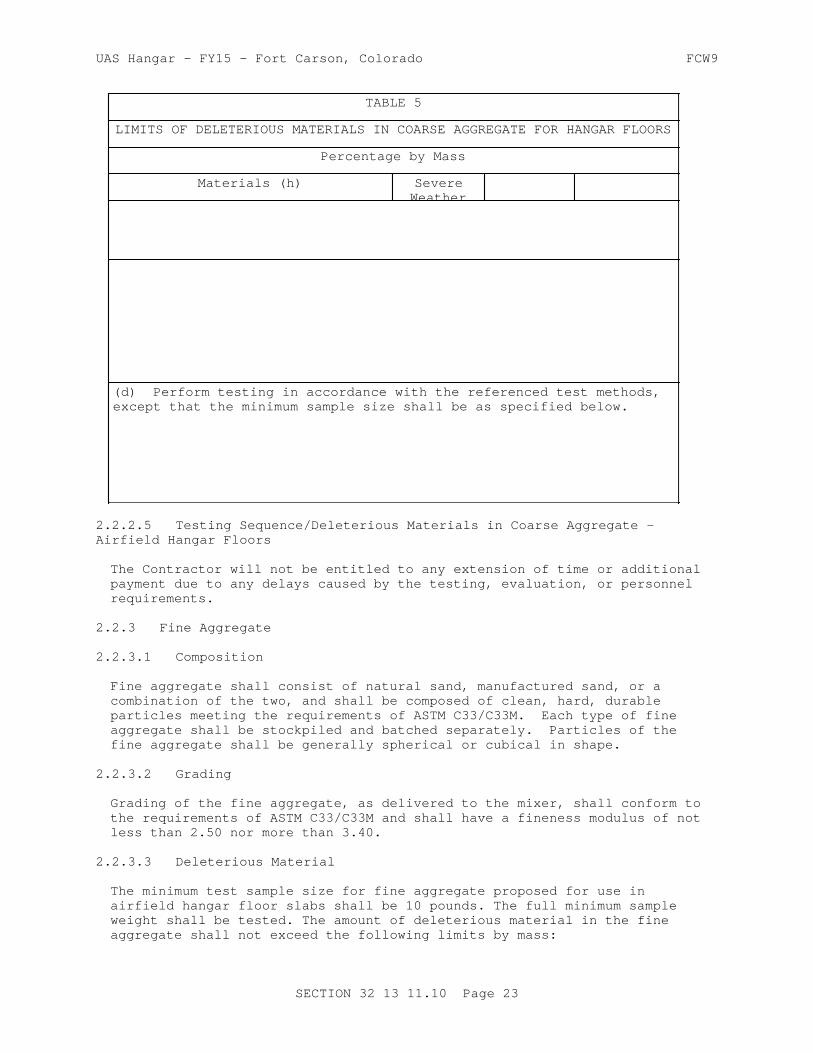
UAS Hangar - FY15 - Fort Carson, Colorado FCW9
TABLE 5
LIMITS OF DELETERIOUS MATERIALS IN COARSE AGGREGATE FOR HANGAR FLOORS
Percentage by Mass
Materials (h) SevereWeather
(d) Perform testing in accordance with the referenced test methods, except that the minimum sample size shall be as specified below.
2.2.2.5 Testing Sequence/Deleterious Materials in Coarse Aggregate - Airfield Hangar Floors
The Contractor will not be entitled to any extension of time or additional payment due to any delays caused by the testing, evaluation, or personnel requirements.
2.2.3 Fine Aggregate
2.2.3.1 Composition
Fine aggregate shall consist of natural sand, manufactured sand, or a combination of the two, and shall be composed of clean, hard, durable particles meeting the requirements of ASTM C33/C33M. Each type of fine aggregate shall be stockpiled and batched separately. Particles of the fine aggregate shall be generally spherical or cubical in shape.
2.2.3.2 Grading
Grading of the fine aggregate, as delivered to the mixer, shall conform to the requirements of ASTM C33/C33M and shall have a fineness modulus of not less than 2.50 nor more than 3.40.
2.2.3.3 Deleterious Material
The minimum test sample size for fine aggregate proposed for use in airfield hangar floor slabs shall be 10 pounds. The full minimum sample weight shall be tested. The amount of deleterious material in the fine aggregate shall not exceed the following limits by mass:
SECTION 32 13 11.10 Page 23
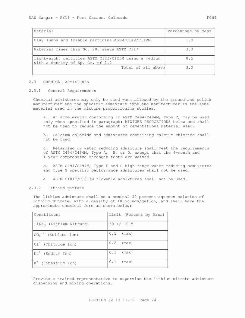
UAS Hangar - FY15 - Fort Carson, Colorado FCW9
Material Percentage by Mass
Clay lumps and friable particles ASTM C142/C142M 1.0
Material finer than No. 200 sieve ASTM C117 3.0
Lightweight particles ASTM C123/C123M using a medium with a density of Sp. Gr. of 2.0
0.5
Total of all above 3.0
2.3 CHEMICAL ADMIXTURES
2.3.1 General Requirements
Chemical admixtures may only be used when allowed by the ground and polish manufacturer and the specific admixture type and manufacturer is the same material used in the mixture proportioning studies.
a. An accelerator conforming to ASTM C494/C494M, Type C, may be used only when specified in paragraph: MIXTURE PROPORTIONS below and shall not be used to reduce the amount of cementitious material used.
b. Calcium chloride and admixtures containing calcium chloride shall not be used.
c. Retarding or water-reducing admixture shall meet the requirements of ASTM C494/C494M, Type A, B, or D, except that the 6-month and 1-year compressive strength tests are waived.
d. ASTM C494/C494M, Type F and G high range water reducing admixtures and Type S specific performance admixtures shall not be used.
e. ASTM C1017/C1017M flowable admixtures shall not be used.
2.3.2 Lithium Nitrate
The lithium admixture shall be a nominal 30 percent aqueous solution of Lithium Nitrate, with a density of 10 pounds/gallon, and shall have the approximate chemical form as shown below:
Constituent Limit (Percent by Mass)
LiNo3 (Lithium Nitrate) 30 +/- 0.5
SO4-2 (Sulfate Ion) 0.1 (max)
Cl- (Chloride Ion) 0.2 (max)
Na+ (Sodium Ion) 0.1 (max)
K+ (Potassium Ion) 0.1 (max)
Provide a trained representative to supervise the lithium nitrate admixture dispensing and mixing operations.
SECTION 32 13 11.10 Page 24

UAS Hangar - FY15 - Fort Carson, Colorado FCW9
2.4 MEMBRANE FORMING CURING COMPOUND
Membrane forming curing compound shall conform to ASTM C309, clear with dye, Type 1-D, Class B.
2.5 WATER
Water for mixing and curing shall be fresh, clean, potable, and free of injurious amounts of oil, acid, salt, or alkali, except that non-potable water, or water from concrete production operations, may be used if it meets the requirements of ASTM C1602/C1602M.
2.6 JOINT MATERIALS
Joint material shall be in accordance with ground and polish manufacturer's written recommendations per 03 35 00.00 10 CONCRETE FINISHING.
2.7 REINFORCING
All reinforcement shall be free from loose, flaky rust, loose scale, oil, grease, mud, or other coatings that might reduce the bond with concrete. Removal of thin powdery rust and tight rust is not required. However, reinforcing steel which is rusted to the extent that it does not conform to the required dimensions or mechanical properties shall not be used.
2.7.1 Reinforcing Bars and Bar Mats
Reinforcing bars shall conform to ASTM A615/A615M, billet-steel or ASTM A996/A996M, rail and axle steel, Grade 60. Bar mats shall conform to ASTM A184/A184M. The bar members may be billet rail or axle steel.
2.7.2 Welded Wire Reinforcement
Welded Wire Reinforcement shall be deformed or smooth, conforming to ASTM A497/A497M or ASTM A185/A185M, and shall be furnished in flat sheets.
2.8 DOWELS
2.8.1 Dowels
Dowels shall be single piece bars fabricated or cut to length at the shop or mill before delivery to the site. Dowels shall be free of loose, flaky rust and loose scale and shall be clean and straight. Dowels may be sheared to length provided that the deformation from true shape caused by shearing does not exceed 0.04 inch on the diameter of the dowel and does not extend more than 0.04 inch from the end of the dowel.
Dowels shall be plain (non-deformed) steel bars conforming to ASTM A615/A615M, Grade 40 or 60; ASTM A996/A996M, Grade 50 or 60. Dowel bars shall be epoxy coated in conformance with ASTM A775/A775M, to include the ends.
Grout retention rings shall be fully circular metal or plastic devices capable of supporting the dowel until the epoxy hardens. Dowel sleeves or inserts are not permitted.
2.8.2 Dowel Bar Assemblies
Dowel bar assemblies shall consist of a framework of metal bars or wires
SECTION 32 13 11.10 Page 25

UAS Hangar - FY15 - Fort Carson, Colorado FCW9
arranged to provide rigid support for the dowels throughout the concrete placement operation, with a minimum of four continuous bars or wires extending along the joint line. The dowels shall be welded to the assembly or held firmly by mechanical locking arrangements that will prevent them from rising, sliding out, or becoming distorted during paving operations.
2.9 EPOXY RESIN
All epoxy-resin materials shall be two-component materials conforming to the requirements of ASTM C881/C881M, Class as appropriate for each application temperature to be encountered, except that in addition, the materials shall meet the following requirements:
a. Material for use for embedding dowels and anchor bolts shall be Type IV, Grade 3.
b. Material for use as patching materials for complete filling of spalls and other voids and for use in preparing epoxy resin mortar shall be Type III, Grade as approved.
c. Material for use for injecting cracks shall be Type IV, Grade 1.
d. Material for bonding freshly mixed portland cement concrete or mortar or freshly mixed epoxy resin concrete or mortar to hardened concrete shall be Type V, Grade as approved.
2.10 EQUIPMENT
All plant, equipment, tools, and machines used in the work shall be maintained in satisfactory working conditions at all times. Submit the following:
a. Details and data on the batching and mixing plant prior to plant assembly including manufacturer's literature showing that the equipment meets all requirements specified herein.
b. Obtain National Ready Mixed Concrete Association (NRMCA) certification of the concrete plant. The concrete plant shall be inspected by an engineer approved by the NRMCA. A list of NRMCA approved engineers is available on the NRMCA website at http://www.nrmca.org. All fees and costs associated with this inspection shall be paid by the Contractor. Submit a copy of the NRMCA QC Manual Section 3 Concrete Plant Certification Checklist, NRMCA Certificate of Conformance, and Calibration documentation on all measuring and weighing devices prior to uniformity testing.
c. A description of the equipment proposed for transporting concrete mixture from the central mixing plant to the paving equipment.
d. A description of the equipment proposed for the machine and hand placing, consolidating and curing of the concrete mixture. Manufacturer's literature on the paver and finisher, together with the manufacturer's written instructions on adjustments and operating procedures necessary to assure a tight, smooth surface on the concrete pavement. The literature shall show that the equipment meets all details of these specifications.
SECTION 32 13 11.10 Page 26

UAS Hangar - FY15 - Fort Carson, Colorado FCW9
2.10.1 Batching and Mixing Plant
a. Location: The batching and mixing plant shall be located off Government premises. There shall be operable telephonic or radio communication between the plant and the placing site at all times concreting is taking place.
b. Type and Capacity: The batching and mixing plant shall be a stationary-type central mix plant, including permanent installations or portable/relocatable plants installed on stable foundations. The plant shall be designed and operated to produce concrete within the specified tolerances, and shall have a capacity of at least 125 cubic yards per hour. The batching and mixing plant shall conform to the requirements of NRMCA QC 3 including provisions addressing:
1. Material Storage and Handling2. Batching Equipment3. Central Mixer4. Ticketing System5. Delivery System
c. Tolerances: The following tolerances shall apply.
Materials Percentage of Required Mass
Cementitious Materials plus or minus 1
Aggregate plus or minus 2
Water plus or minus 1
Admixture plus or minus 3
For volumetric batching equipment for water and admixtures, the above numeric tolerances shall apply to the required volume of material being batched. Concentrated admixtures shall be uniformly diluted, if necessary, to provide sufficient volume per batch to ensure that the batchers will consistently operate within the above tolerance.
d. Moisture Control: The plant shall be capable of ready adjustment to compensate for the varying moisture contents of the aggregates and to change the quantities of the materials being batched. An electric moisture meter complying with the provisions of COE CRD-C 143 shall be provided for measuring of moisture in the fine aggregate. The sensing element shall be arranged so that measurement is made near the batcher charging gate of the fine aggregate bin or in the fine aggregate batcher.
2.10.2 Concrete Mixers
a. General: Mixers shall be stationary or truck mixers. Mixers shall be capable of combining the materials into a uniform mixture and of discharging this mixture without segregation. The mixers shall not be charged in excess of the capacity recommended by the manufacturer. The mixers shall be operated at the drum or mixing blade speed designated by the manufacturer. The mixers shall be maintained in satisfactory operating condition, and the mixer drums shall be kept free of hardened concrete. Mixer blades or paddles shall be replaced when worn down
SECTION 32 13 11.10 Page 27

UAS Hangar - FY15 - Fort Carson, Colorado FCW9
more than 10 percent of their depth when compared with the manufacturer's dimension for new blades or paddles.
b. Stationary: Stationary mixers shall be drum or pan mixers. Mixers shall be provided with an acceptable device to lock the discharge mechanism until the required mixing time has elapsed.
c. Mixing Time and Uniformity for Stationary Mixers: For stationary mixers, before uniformity data are available, the mixing time for each batch after all solid materials are in the mixer, provided that all of the mixing water is introduced before one-fourth of the mixing time has elapsed, shall be 1 minute for mixers having a capacity of 1 cubic yard. For mixers of greater capacity, this minimum time shall be increased 20 seconds for each additional 1.33 cubic yard or fraction thereof. After results of uniformity tests are available, the mixing time may be reduced to the minimum time required to meet uniformity requirements; but if uniformity requirements are not being met, the mixing time shall be increased as directed. Mixer performance tests at new mixing times shall be performed immediately after any change in mixing time. The Regular Test sequence shall be conducted for initial determination of the mixing time or as directed. When regular testing is performed, the concrete shall meet the limits of any five of the six uniformity requirements listed in Table 1 below.
d. The Abbreviated Test sequence shall be conducted for production concrete verification at the frequency specified in Table 6. When abbreviated testing is performed, the concrete shall meet only those requirements listed for abbreviated testing. The concrete proportions used for uniformity tests shall be the contractor submitted and approved concrete mixtures for full production. Aggregate gradation testing from plant belt samples shall be performed the day prior to uniformity testing. The combine gradation shall be calaculated based on actual batching tickets produced during uniformity testing along with aggregate belt sample test results taken from the day before uniformity testing. Regular testing shall consist of performing all six tests on three batches of concrete. The range for regular testing shall be the average of the ranges of the three batches. Abbreviated testing shall consist of performing the three required tests on a single batch of concrete. The range for abbreviated testing shall be the range for one batch. If more than one mixer is used and all are identical in terms of make, type, capacity, condition, speed of rotation, etc., the results of tests on one of the mixers shall apply to the others, subject to the approval of the Contracting Officer. All mixer performance (uniformity) testing shall be performed in accordance with COE CRD-C 55 and with paragraph titled TESTING AND INSPECTION FOR CONTRACTOR QUALITY CONTROL DURING CONSTRUCTION in PART 3.
TABLE 1 UNIFORMITY REQUIREMENTS--STATIONARY MIXERS
Parameter Regular Tests Allowable Maximum Range for Average of 3 Batches
Abbreviated Tests Allowable Maximum Range for 1 Batch
Unit weight of air-free mortar
2.0 lbs/cubic ft 2.0 lbs/cubic ft
Air content 1.0 percent --
SECTION 32 13 11.10 Page 28

UAS Hangar - FY15 - Fort Carson, Colorado FCW9
TABLE 1 UNIFORMITY REQUIREMENTS--STATIONARY MIXERS
Parameter Regular Tests Allowable Maximum Range for Average of 3 Batches
Abbreviated Tests Allowable Maximum Range for 1 Batch
Slump 1.0 inch 1.0 inch
Coarse aggregate 6.0 percent 6.0 percent
Compressive strength at 7 days
10.0 percent 10.0 percent
Water content 1.5 percent
Note: Two 6x6 inch flexural beams shall be fabricated and tested at 14 days of age in accordance to ASTM C 78 during the uniformity testing to validate cylinder to beam correlation ratios if applicable, see paragraph "Concrete Strength Testing for Contractor CQC".
e. Truck Mixers: The only truck mixers used for mixing or transporting paving concrete shall be those designed with extra large blading and rear opening specifically for low-slump paving concrete. Truck mixers, the mixing of concrete therein, and concrete uniformity and testing thereof shall conform to the requirements of ASTM C94/C94M. The number of revolutions between 70 to 100 for truck-mixed concrete and the number of revolutions for shrink-mixed concrete shall be determined by uniformity tests as specified in ASTM C94/C94M and in requirements for mixer performance stated in paragraph TESTING AND INSPECTION FOR CONTRACTOR QUALITY CONTROL in PART 3. If requirements for the uniformity of concrete are not met with 100 revolutions of mixing after all ingredients including water are in the truck mixer drum, the mixer shall not be used until the condition is corrected. Water shall not be added after the initial introduction of mixing water except, when on arrival at the job site, the slump is less than specified and the water-cement ratio is less than that given as a maximum in the approved mixture. Additional water may be added to bring the slump within the specified range provided the approved water-cement ratio is not exceeded. Water shall be injected into the head of the mixer (end opposite the discharge opening) drum under pressure, and the drum or blades shall be turned a minimum of 30 additional revolutions at mixing speed. Water shall not be added to the batch at any later time. Mixer performance (uniformity) tests for truck mixers shall be made in accordance with ASTM C94/C94M.
2.10.3 Transporting Equipment
Fixed form concrete shall be transported in approved truck mixers designed with extra large blading and rear opening specifically for low slump concrete. All transporting equipment shall be designed and operated to deliver and discharge the required concrete mixture completely without segregation.
2.10.4 Transfer and Spreading Equipment
Equipment for transferring concrete from the transporting equipment to the paving lane in front of the paver shall be specially manufactured, self-propelled transfer equipment which will accept the concrete outside the paving lane and will transfer and spread it evenly across the paving
SECTION 32 13 11.10 Page 29

UAS Hangar - FY15 - Fort Carson, Colorado FCW9
lane in front of the paver and strike off the surface evenly to a depth which permits the paver to operate efficiently. The maximum drop height shall be 3 feet.
2.10.5 Paver-Finisher
The following items a through e apply to fixed-form.
a. General: Heavy duty vibrating truss screeds or pans shall be used for placement of the hangar floor pavement.
b. Vibrators: Spud vibrators shall be operated from a work bridge in front of a vibrating truss screed. All vibrators shall be operated at the desired depth within the slab and completely withdrawn from the concrete, as required. Spud vibrators shall operate at a frequency of not less than 8000 impulses/minute and an amplitude of not less than 0.03 inch, as determined by COE CRD-C 521. The head diameter of the spud vibratory shall be in accordance with ACI 309R for the pavement thickness being placed. The concrete shall be properly consolidated by vibrating to the required depth by systematic vibration at a maximum spacing equal to 1.5 times the effective radius of influence or a maximum spacing of 30 inches, whichever is less. Consolidation shall be performed within of 12 inches from the fixed forms.
c. Screed Plate: The screed shall strike off the surface of the concrete from the top of the form in one pass, multiple passes of the screed are not allowed. The scredd shall smooth the surface and shall so finish the surface that no significant amount of hand finishing, except use of cutting straightedges, is required. The entire machine shall provide adjustment for variation in lane width or thickness and to prevent more than 8 inches of the screed or extrusion plate extending over previously placed concrete on either end when paving fill-in lanes. Machines that cause displacement of properly installed forms and machines that cause frequent delays due to mechanical failures shall be replaced as directed.
d. Other Types of Finishing Equipment: Clary screeds, laser screeds, rotating tube floats, or bridge deck finishers are not allowed.
f. Form Riding Machines: Form riding pavers may be used. The form rideing machine shall be equipped with wheels designed to ride the forms, keep it aligned with the forms, and spread the load so as to prevent deformation of the forms. Form riding machines traveling on guide rails located outside the paving lane shall be equipped with wheels when traveling on new or existing concrete to remain.
2.10.6 Curing Equipment
Equipment for applying membrane-forming curing compound shall use compressed air supplied by a mechanical air compressor. Calibrate the spraying system in accordance with ASTM D2995, Method A, for the rate of application required in paragraph: Membrane Curing. If the curing equipment fails to apply an even coating of compound at the specified rate, it shall immediately be replaced.
2.10.7 Sawing Equipment
Equipment for sawing joints and for other similar sawing of concrete shall be standard diamond-type concrete saws mounted on a wheeled chassis which
SECTION 32 13 11.10 Page 30

UAS Hangar - FY15 - Fort Carson, Colorado FCW9
can be easily guided to follow the required alignment. Blades shall be diamond tipped. If demonstrated to operate properly, abrasive blades may be used. Provide spares as required to maintain the required sawing rate. All saws shall be capable of sawing to the full depth required. Early-entry saws may be used, subject to demonstration and approval of the Contracting Officer. No change to the initial sawcut depth shall be permitted.
2.10.8 Straightedge
Furnish and maintain at the job site, in good condition, one 12 foot straightedge for each paving train for testing the hardened portland cement concrete surfaces. These straightedges shall be constructed of aluminum or magnesium alloy and shall have blades of box or box-girder cross section with flat bottom, adequately reinforced to insure rigidity and accuracy. Straightedges shall have handles for operation on the pavement.
2.10.9 Work Bridge
Furnish a working bridge capable of spanning the required paving lane width where workmen can efficiently and adequately reach the pavement surface.
2.11 SPECIFIED CONCRETE STRENGTH AND OTHER PROPERTIES
2.11.1 Specified Flexural Strength
Specified flexural strength, R, for concrete is 650 psi at 90 days, as determined by equivalent flexural strength, as specified in paragraph: Mixture Proportioning for Flexural Strength below.
2.11.2 Water-Cementitious Materials Ratio
Maximum allowable water-cementitious material ratio is 0.45. The water-cementitious material ratio will be the equivalent water-cement ratio as determined by conversion from the weight ratio of water to cement plus SCM by the mass equivalency method described in ACI 211.1.
2.11.3 Air Content
Air entrainment shall not be used. Building shall be enclosed and protected to freeze/thaw cycles prior to pouring of slab.
2.11.4 Slump
The maximum allowable slump of the concrete at the point of placement shall be 3 inchesfor pavement constructed with fixed forms. The selected slump shall be applicable to both pilot and fill-in lanes.
2.11.5 Concrete Temperature
The temperature of the concrete as delivered shall conform to the requirements of paragraphs, Paving in Hot Weather and Paving in Cold Weather, in PART 3. Temperature of concrete shall be determined in accordance with ASTM C1064/C1064M.
2.11.6 Concrete Strength for Final Acceptance
The strength of the concrete will be considered acceptable when the average equivalent 90-day flexural strengths for each lot are above the 'Specified
SECTION 32 13 11.10 Page 31
UAS Hangar - FY15 - Fort Carson, Colorado FCW9
Flexural Strength' as determined by correlation with 14-day compressive strength tests specified in paragraph: "Mixture Proportioning for Flexural Strength" below, and no individual set (2 specimens per sublot) in the lot are 25 psi or more below the equivalent 'Specified Flexural Strength'. If any lot or sublot, respectively, fails to meet the above criteria, the lot or sublot shall be removed and replaced at no additional cost to the Government. This is in addition to and does not replace the average strength required for day-to-day CQC operations as specified in paragraph: Average CQC Flexural Strength Required for Mixtures, below.
2.12 MIXTURE PROPORTIONS
2.12.1 Composition
Concrete shall be composed of cementitious material, water, fine and coarse aggregates, and admixtures. Supplementary Cementitious Materials (SCM) choice and usage shall be in accordance with paragraph: Supplementary Cementitious Materials (SCM) Content. The total cementitious material content shall be at least 517 lb./cu. yd. All concrete hangar floor slabs or rail door slabs exposed to freezing and thawing shall contain an air entraining admixtures. For interior hangar floor slabs not exposed to freezing and thawing the contractor may eliminate the air-entraining admixture if a requested in writing and approved by the Contracting Officer. The contractor shall protect the hangar floor from freezing at all times if an air eintraining admixture is not used in the concrete mixture for interior hangar floor slabs only. Any non air-entrained concrete that is subject to any freezing shall be removed and replaced at no additional cost or time extension to the Government. A normal range water reducing admixtures shall be used.
2.12.2 Proportioning Studies
Trial design batches, mixture proportioning studies, and testing requirements are the responsibility of the Contractor. Submit narrative discussing methodology on how the mix design was developed and the results of the mixture proportioning studies signed and stamped by the registered professional engineer having technical responsibility for the mix design study, and submitted at least 30 days prior to commencing concrete placing operations. The results shall include a statement giving the maximum nominal coarse aggregate size and the weights and volumes of each ingredient proportioned on a one cubic yard basis. Aggregate quantities shall be based on the mass in a saturated surface dry condition. The recommended mixture proportions shall be accompanied by test results demonstrating that the proportions selected will produce concrete of the qualities indicated. Trial mixtures having proportions, slumps, and air content when applicable suitable for the work shall be based on methodology described in ACI 211.1, modified as necessary to accommodate flexural strength. Submit test results including:
a. Coarse and fine aggregate gradations and plots.b. Combined aggregate gradation and coarseness/workability plots.c. Coarse aggregate quality test results, include deleterious materials.d. Fine aggregate quality test results.e. Mill certificates for cement and supplemental cementitious materials.f. Certified test results for air entraining, water reducing, retarding, non-chloride accelerating admixtures.g. Specified flexural strength, slump, and air content.h. Documentation of required average CQC flexural strength, Ra.i. Recommended proportions/volumes for proposed mixture and each of
SECTION 32 13 11.10 Page 32

UAS Hangar - FY15 - Fort Carson, Colorado FCW9
three trial water-cementitious materials ratios.j. Individual beam and cylinder breaks.k. Flexural and compressive strength summaries and plots.l. Correlation ratios for acceptance testing and CQC testing.m. Historical record of test results, documenting production standard deviation (if available).
2.12.2.1 Water-Cementitious Materials Ratio
At least three different water-cementitious materials ratios, which will produce a range of strength encompassing that required on the project, shall be used. The maximum allowable water-cementitious material ratio required in paragraph: Specified Flexural Strength, above will be the equivalent water-cementitious materials ratio. The maximum water-cementitious materials ratio of the approved mix design shall become the maximum water-cementitious materials ratio for the project, and in no case shall exceed the value stated in paragraph Water-Cementitious Materials Ratio.
2.12.2.2 Trial Mixture Studies
Separate sets of trial mixture studies shall be made for each combination of cementitious materials and each combination of admixtures proposed for use. No combination of either shall be used until proven by such studies, except that, if approved in writing and otherwise permitted by these specifications, an accelerator or a retarder may be used without separate trial mixture study. The temperature and unit weight of concrete in each trial batch shall be reported. Each mixture shall be designed to promote easy and suitable concrete placement, consolidation and finishing, and to prevent segregation and excessive bleeding. Laboratory trial mixtures shall be proportioned for maximum permitted slump and air content.
2.12.2.3 Mixture Proportioning for Flexural Strength
The following step by step procedure shall be followed:
a. Fabricate all beams for each mixture from the same batch or blend of batches. Fabricate and cure all beams and cylinders in accordance with ASTM C192/C192M, using 6 x 6 inch steel beam forms.
b. Cure test beams from each mixture for 7, 14, 90-day flexural tests; 6 beams to be tested per age.
c. Test beams in accordance with ASTM C78/C78M, c.
d. Using the average strength for each w/c at each age, plot all results from each of the three mixtures on separate graphs for w/c versus:
7-day flexural strength14-day flexural strength90-day flexural strength
7-day compressive strength14-day compressive strength90-day compressive strength
e. From these graphs select a w/c that will produce a mixture giving a 90-day flexural strength equal to the required strength determined in
SECTION 32 13 11.10 Page 33
UAS Hangar - FY15 - Fort Carson, Colorado FCW9
accordance with the next paragraph.
f. Using the above selected w/c, select from the graphs the expected 7, 14, 90-day flexural strengths and the expected 7, 14, 90-day compressive strengths for the mixture.
g. From the above expected strengths for the selected mixture determine the following Correlation Ratios:
(1) Ratio of the 14-day compressive strength of the selected mixture to the 90-day flexural strength of the mixture (for acceptance).
(2) Ratio of the 7-day compressive strength of the selected mixture to the 90-day flexural strength of the mixture (for CQC control).
h. If there is a change in materials, additional mixture design studies shall be made using the new materials and new Correlation Ratios shall be determined.
i. No concrete pavement shall be placed until the Contracting Officer has approved the Contractor's mixture proportions. The approved water-cementitious materials ratio shall not exceed the maximum value specified in the next paragraph and shall not be increased without the Contracting Officer's written approval.
2.12.3 Average CQC Flexural Strength Required for Mixtures
In order to ensure meeting the strength requirements specified in paragraph: SPECIFIED CONCRETE STRENGTH AND OTHER PROPERTIES above, during production, the mixture proportions selected during mixture proportioning studies and used during construction shall produce a required average CQC flexural strength exceeding the specified strength, R, by the amount indicated below. This required average CQC flexural strength, Ra, will be used only for CQC operations as specified in paragraph: TESTING AND INSPECTION FOR CONTRACTOR QUALITY CONTROL in PART 3 and as specified in the previous paragraph. During production, the required Ra shall be adjusted , as appropriate and as approved, based on the standard deviation of equivalent 90-day strengths being attained during paving.
a. From Previous Test Records: Where a concrete production facility has previous test records current to within 18 months, a standard deviation shall be established in accordance with the applicable provisions of ACI 214R. Test records from which a standard deviation is calculated shall represent materials, quality control procedures, and conditions similar to those expected, shall represent concrete produced to meet a specified flexural strength or strengths within 150 psi of the 90-day flexural strength specified for the proposed work, and shall consist of at least 30 consecutive tests. Perform verification testing, as directed by the Contracting Officer, to document the current strength. A strength test shall be the average of the strengths of two specimens made from the same sample of concrete and tested at 90 days. Required average CQC flexural strength, Ra, used as the basis for selection of concrete proportions shall be the value from the equation that follows, using the standard deviation as determined above:
Ra = R + 1.34S
Where: S = standard deviationR = specified flexural strength
SECTION 32 13 11.10 Page 34

UAS Hangar - FY15 - Fort Carson, Colorado FCW9
Ra = required average flexural strength
Where a concrete production facility does not have test records meeting the requirements above but does have a record based on 15 to 29 consecutive tests, a standard deviation shall be established as the product of the calculated standard deviation and a modification factor from the following table:
NUMBER OF TESTS MODIFICATION FACTOR FOR STANDARD DEVIATION
15 1.16
20 1.08
25 1.03
30 or more 1.00
b. Without Previous Test Records: When a concrete production facility does not have sufficient field strength test records for calculation of the standard deviation, the required average strength, Ra, shall be determined by adding 15 percent to the specified flexural strength, R.
PART 3 EXECUTION
3.1 PREPARATION FOR PAVING
Before commencing paving, perform the following. Forms shall be in place, cleaned, coated, and adequately supported. Any reinforcing steel needed shall be at the paving site. All transporting and transfer equipment shall be ready for use, clean, and free of hardened concrete and foreign material. Equipment for spreading, consolidating, screeding, finishing, and texturing concrete shall be at the paving site, clean and in proper working order. All equipment and material for curing and for protecting concrete from weather or mechanical damage shall be at the paving site, in proper working condition, and in sufficient amount for the entire placement.
3.1.1 Weather Precaution
When windy conditions during paving appear probable, equipment and material shall be at the paving site to provide windbreaks, shading, fogging, or other action to prevent plastic shrinkage cracking or other damaging drying of the concrete.
3.1.2 Proposed Techniques
Submit placing and protection methods; paving sequence; jointing pattern; data on curing equipment; and demolition of existing pavements, as specified; pavement diamond grinding equipment and procedures. Submit for approval the following items:
a. A description of the placing and protection methods proposed when concrete is to be placed in or exposed to hot, cold, or rainy weather conditions.
b. A detailed paving sequence plan and proposed paving layout showing all planned construction joints; transverse and longitudinal dowel bar spacing; and identifying pilot lanes and hand placement areas. No
SECTION 32 13 11.10 Page 35

UAS Hangar - FY15 - Fort Carson, Colorado FCW9
deviation from the jointing layout shown on the drawings shall be made without written approval of the designer of record.
c. Joint sawing plan and equipment proposed to control alignment of sawn joints within the specified tolerances.
d. Data on the curing equipment, media and methods to be used to include initial applicaton, monitoring integrity of the applicatoin, and reapplication requirements as needed.
e. Pavement demolition work plan, presenting the proposed methods and equipment to remove existing pavement and protect pavement to remain in place.
3.2 CONDITIONING OF UNDERLYING MATERIAL
3.2.1 General Procedures
Underlying granular material, upon which the insulation is to be placed shall be clean, damp, and free from debris, waste concrete or cement, frost, ice, and standing or running water. Prior to setting forms or placement of concrete, the underlying base materials shall be well drained and shall have been satisfactorily graded and uniformly compacted in accordance with the applicable Section of these specifications. High areas shall be trimmed to proper elevation. Low areas shall be filled and compacted to a condition similar to that of surrounding grade. Any underlyingbase materials disturbed by construction operations shall be reworked and recompacted to specified density.
3.2.2 Insulation
INSULATION shall installed, complete, and approved by the contracting officer prior to placement of radiant slab heat piping.
3.2.3 Radiant Slab Heating Sytem
Install per 23 52 00 RADIANT SLAB HEATING SYSTEM.
3.2.4 Traffic on Underlying Material
After the underlying material has been prepared for concrete placement, no equipment shall be permitted thereon. Subject to specific approval, crossing of the prepared underlying material at specified intervals for construction purposes may be permitted, provided rutting or indentations do not occur. The surface shall be reworked and reprepared to the satisfaction of the Contracting Officer before concrete is placed. No transporting equipment shall be allowed to operate on the prepared and compacted underlying material. No foot traffic shall be allowed on the approved underlying layer prior to placement of concrete. No workers shall be allowed in the paving lane during concrete placement except from on a working bridge.
3.3 WEATHER LIMITATIONS
3.3.1 Placement and Protection During Inclement Weather
Do not commence placing operations when heavy rain or other damaging weather conditions appear imminent. At all times when placing concrete, maintain on-site sufficient waterproof cover and means to rapidly place it
SECTION 32 13 11.10 Page 36

UAS Hangar - FY15 - Fort Carson, Colorado FCW9
over all unhardened concrete or concrete that might be damaged by rain. Suspend placement of concrete whenever rain, high winds, or other damaging weather commences to damage the surface or texture of the placed unhardened concrete, washes cement out of the concrete, or changes the water content of the surface concrete. All unhardened concrete shall be immediately covered and protected from the rain or other damaging weather. Any slab damaged by rain or other weather shall be completely removed full depth, by full slab width, to the nearest original joint, and replaced at the Contractor's expense as specified in paragraph: REPAIR, REMOVAL AND REPLACEMENT OF NEWLY CONSTRUCTED SLABS below.
3.3.2 Paving in Hot Weather
When the ambient temperature during paving is expected to exceed 90 degrees F, the concrete shall be properly placed and finished in accordance with procedures previously submitted, approved, and as specified herein. The concrete temperature at time of delivery to the forms shall not exceed the temperature shown in the table below when measured in accordance with ASTM C1064/C1064M. Cooling of the mixing water or aggregates or placing in the cooler part of the day may be required to obtain an adequate placing temperature. Steel forms and reinforcing shall be cooled as needed to maintain steel temperatures below 120 degrees F. Transporting and placing equipment shall be cooled or protected if necessary to maintain proper concrete placing temperature. The finished surfaces of the newly laid pavement shall be kept damp by applying a fog spray (mist) with approved spraying equipment until the pavement is covered by the curing medium.
Maximum Allowable Concrete Placing Temperature
Relative Humidity, Percent,During Time of Concrete
Maximum Allowable ConcreteTemperature in Degrees F
Greater than 60 95
40-60 85
Less than 40 80
3.3.3 Prevention of Plastic Shrinkage Cracking
During weather with low humidity, and particularly with high temperature and appreciable wind, develop and institute measures to prevent plastic shrinkage cracks from developing. If plastic shrinkage cracking occurs, halt further placement of concrete until protective measures are in place to prevent further cracking. Periods of high potential for plastic shrinkage cracking can be anticipated by use of ACI 305R. In addition to the protective measures specified in the previous paragraph, the concrete placement shall be further protected by erecting shades and windbreaks and by applying fog sprays of water, the addition of monomolecular films, or wet covering. Apply monomolecular films after finishing is complete, do not use in the finishing process. When such water treatment is stopped, curing procedures shall be immediately commenced. Plastic shrinkage cracks that occur shall be repaired in accordance with paragraph: REPAIR, REMOVAL AND REPLACEMENT OF NEWLY CONSTRUCTED SLABS. Plastic shrinkage cracks shall never be troweled over or filled with slurry.
SECTION 32 13 11.10 Page 37
UAS Hangar - FY15 - Fort Carson, Colorado FCW9
3.3.4 Paving in Cold Weather
Cold weather paving shall conform to ACI 306R. Special protection measures, as specified herein, shall be used if freezing temperatures are anticipated or occur before the expiration of the specified curing period. Placement of concrete shall not begin unless the ambient temperature is at least 35 degrees F and rising. Thereafter, placement of concrete shall be halted whenever the ambient temperature drops below 40 degrees F. When the ambient temperature is less than 50 degrees F, the temperature of the concrete when placed shall be not less than 50 degrees F nor more than 75 degrees F. Heating of the mixing water or aggregates will be required to regulate the concrete placing temperature. Materials entering the mixer shall be free from ice, snow, or frozen lumps. Salt, chemicals or other materials shall not be incorporated in the concrete to prevent freezing. If allowed under paragraph: MIXTURE PROPORTIONS in PART 2, an accelerating admixture may be used when the ambient temperature is below 50 degrees F. Covering and other means shall be provided for maintaining the concrete at a temperature of at least 50 degrees F for not less than 72 hours after placing, and at a temperature above freezing for the remainder of the curing period. Remove pavement slabs, full depth by full width, damaged by freezing or falling below freezing temperature to the nearest planned joint, and replace at the Contractor's expense as specified in paragraph REPAIR, REMOVAL AND REPLACEMENT OF NEWLY CONSTRUCTED SLABS.
3.4 CONCRETE PRODUCTION
Batching, mixing, and transporting equipment shall have a capacity sufficient to maintain a continuous, uniform forward movement of the placement equipment. Concrete transported in non-agitating equipment shall be deposited in front of the paver within 45 minutes from the time cement has been charged into the mixing drum, except that if the ambient temperature is above 90 degrees F, the time shall be reduced to 30 minutes. Concrete transported in truck mixers shall be deposited in front of the paver within 90 minutes from the time cement has been charged into the mixer drum of the plant or truck mixer. If the ambient temperature is above 90 degrees F, the time shall be reduced to 60 minutes. Every load of concrete delivered to the paving site shall be accompanied by a batch ticket from the operator of the batching plant. Tickets shall be on approved forms and shall show at least but not limited to date batched, job name, project name, mix identification, load size, length of batch mixing, truck number, approved design proportioning by mass of individual materials including water and admixtures, individual materials target batch masses, actual batch masses, errors in batching indivdual masses, moisture contents of aggregates, trim or hold water, actual w/c+p ratio (or volumes if applicable) for each batch of concrete delivered to the project paving site, the water meter and revolution meter reading on truck mixersif applicable and the time of day. Tickets for each truck shall be delivered as part of the lot acceptance package to the placing foreman who shall keep them on file and deliver them to the Government weekly, or as directed by the Contracting Officer.
3.4.1 Batching and Mixing Concrete
Scale pivots and bearings shall be kept clean and free of rust. Any equipment which fails to perform as specified shall immediately be removed from use until properly repaired and adjusted, or replaced.
SECTION 32 13 11.10 Page 38

UAS Hangar - FY15 - Fort Carson, Colorado FCW9
3.4.2 Transporting and Transfer - Spreading Operations
Concrete shall be deposited as close as possible to its final position in the paving lane. All equipment shall be operated to discharge and transfer concrete without segregation. In no case shall dumping of concrete in discrete piles which requires the use of front-end loaders, dozers, or similar equipment to distribute the concrete will be permitted.
3.5 PAVING
3.5.1 General Requirements
Pavement shall be constructed with vibratory truss screeds or form rider paving equipment and finishing equipment utilizing rigid fixed forms. Paving equipment and its operation shall be controlled, and coordinated with all other operations, such that the paver-finisher has a continuous forward movement, at a reasonably uniform speed, from beginning to end of each paving lane, except for inadvertent equipment breakdown. Backing up the paving equipmenton previously placed concrete and refinishing a lane is not permitted. Remove and replace concrete refinished in this manner. Failure to achieve a relatively continuous forward motion requires halting operations, regrouping, and modifying operations to achieve this requirement. Personnel and construction equipment shall not be permitted to walk or operate in the plastic concrete at any time.
3.5.2 Consolidation
Concrete shall be consolidated with an approved hand-operated immersion vibratoroperated from a work bridge spanning the placement. The vibrators shall be inserted into the concrete to a depth that will provide the best full-depth consolidation but not closer to the underlying material than 2 inches. Excessive vibration shall not be permitted. Vibrators shall not be used to transport or spread the concrete.
Hand-operated vibrators shall not be operated in the concrete at one location for more than 20 seconds. Insertion locations for hand-operated vibrators shall be between 6 to 15 inches on centers. Gang-mounted vibrators shall be adjusted to the rate of travel of the concrete placement and shall cease to operate as soon as the concrete placement forward motion has ceased.
Lack of an operational hand operated vibrator or the required number of gang vibrators shall require the immediate stoppin og the concrete placement operation. Any evidence of inadequate consolidation (honeycomb along the edges, large air pockets, or any other evidence) shall require the immediate stopping of the paving operation and approved adjustment of the equipment or procedures.
3.5.3 Operation
When the concrete placement/finishing equipment approaches a header at the end of a floor lane, a sufficient amount of concrete shall be maintained ahead of the concrete placement/finishing equipment to provide a roll of concrete which will spill over the header. The amount of extra concrete shall be sufficient to prevent any slurry that is formed and carried along ahead of the concrete placement/finishing equipment from being deposit3ed adjacent to the header.
When the concrete placement/finishing equipment is operated in a fill-in
SECTION 32 13 11.10 Page 39

UAS Hangar - FY15 - Fort Carson, Colorado FCW9
lane (between or adjacent to previously constructed floor lanes), provisions shall be made to prevent damage to the previously constructed floor. Screeds shall be controlled from the previously placed floor so as to prevent damage to the previously constructed floor. Screeds shall be controlled from the previously placed floor so as to prevent them from applying pressure to the existing floor and to prevent abrasion of the floor surface. The overlapping area of existing floor surface shall at all times be kept completely free of any loose or bonded foreign material as the concrete placement/finishing equipment operates across it.
Concrete placement/finishing equipment using transversely oscillating screeds shall not be used to form fill-in lanes that have widths less than a full width for which the concrete placement/finishing equipment was designed or adjusted.
3.5.4 Required Results
The concrete placement/finishing equipment, and its gang-mounted or hand-held vibrators, shall be adjusted and operated and coordinated with the concrete mixture being used to produce a consolidated concrete throughout the floor lane under construction, true to line and grade within specified tolerances. The concrete placement/finishing operation shall produce a surface finish free of irregularities, tears, voids of any kind, and any other discontinuities. The concrete placement/finishing shall make only one pass across the floor lane; multiple passes will not be permitted.
The concrete placement/finishing equipment and its operation shall produce a finished surface requiring no hand finishing other than the use of cutting straightedges, except in very infrequent instances. If any equipment or operation fails to produce the above results, the paving shall be stopped, the equipment shall be replaced or properly adjusted, the operation shall be appropriately modified, or the mixture proportions modified, in order to produce the required results before recommencing paving. No water, other than fog sprays (mist) as specified in paragraph: Prevention of Plastic Shrinkage Cracking above, shall be applied to the concrete or the concrete surface during concrete placement and finishing.
3.5.5 Fixed Form Paving
Concrete placement equipment for fixed-form paving and the operation thereof shall conform to the requirements of paragraph EQUIPMENT, and all requirements specified herein.
3.5.5.1 Forms for Fixed-Form Paving
a. Forms shall be positioned on the prepared grade in accordance with the submitted construction layout plan. Form sections shall be tightly locked and shall be free from play or movement in any direction. Forms shall be provided with adequate devices for secure settings so that when in place they will withstand, without visible spring or settlement, the impact and vibration of the consolidating and finishing equipment.
c. Set forms for full bearing on foundation for entire length and width and in alignment with edge of finished pavement. Support forms during entire operation of placing, compaction, and finishing so that forms will not deviate vertically more than 0.01 foot from required grade and elevations indicated. Conformity to the alignment and grade elevations
SECTION 32 13 11.10 Page 40

UAS Hangar - FY15 - Fort Carson, Colorado FCW9
shown on the drawings shall be checked and necessary corrections shall be made immediately prior to placing the concrete. The forms shall be cleaned and oiled each time before concrete is placed. No concrete shall be placed until setting of forms has been checked and approved by the CQC team.
d. Do not anchor guide rails for fixed form concrete placement/ finishing equipment into new concrete or existing concrete to remain.
3.5.5.2 Form Removal
Keep forms in place at least 12 hours after the concrete has been placed. When conditions are such that the early strength gain of the concrete is delayed, leave the forms in place for a longer time, as directed. Remove forms by procedures that do not injure the concrete. Bars or heavy metal tools shall not be used directly against the concrete in removing the forms. Any concrete found to be defective after form removal shall be repaired promptly, using procedures specified or as directed.
3.5.6 Placing Reinforcing Steel
The type and amount of steel reinforcement shall be as shown on the drawings.
3.5.6.1 Pavement Thickness Less Than 12 Inches
For floors less than 12 inches thick, the reinforcement shall be positioned on suitable chairs or continuous mesh support devices securely fastened to the subgrade prior to concrete placement. Concrete shall be vibrated after the steel has been placed. Regardless of placement procedure, the reinforcing steel shall be free from coatings which could impair bond between the steel and concrete, and laps in the reinforcement shall be as indicated.
Regardless of the equipment or procedures used for installing reinforcement, ensure that the entire depth of concrete is adequately consolidated.
3.5.7 Placing Dowels
The method used in installing and holding dowels in position shall ensure that the error in alignment of any dowel from its required horizontal and vertical alignment after the floort has been completed shall meet the following requirements:
1. Skew or tilt in the vertical or the horizontal plane shall not be greater than 1/2 inch per foot of length of the dowel bar.2. Except as otherwise specified below, horizontal spacing of dowels shall be within a tolerance of plus or minus 1 inch.3. The vertical location on the face of the slab shall be within a tolerance of plus or minus 1 inch. The vertical alignment of the dowels shall be measured parallel to the designated top surface of the floor.
Dowels across crowns and other joints at grade changes shall be measured to a level surface. Horizontal alignment shall be checked perpendicular to the joint edge. The horizontal alignment shall be checked with a framing square before concrete placement or using a nondestructivve test device after the concrete has hardened.
SECTION 32 13 11.10 Page 41
UAS Hangar - FY15 - Fort Carson, Colorado FCW9
Dowels shall not be placed closer than 0.6 times the dowel bar length to the planned joint line. If the last regularly spaced longitudinal dowel is closer than that dimension, it shall be moved away from the joint to a location 0.6 times the dowel bar length, but not closer than 6 inches to its nearest neighbor. Dowel interference at a transverse joint-longitudinal joint intersection shall be resolved by deleting the closest transverse dowel. Dowels shall be installed as specified in the following subparagraphs.
3.5.7.1 Contraction Joints
Dowels in longitudinal and transverse contraction joints within the paving lane shall be held securely in place, as indicated, by means of rigid metal frames or basket assemblies of an approved type. The basket assemblies shall be held securely in the proper location by means of suitable pins or anchors. Do not cut or crimp the dowel basket tie wires.
3.5.7.2 Construction Joints-Dowels Installed in Fresh Concrete
Install dowels by the bonded-in-place method. Dowels shall be placed across joints where indicated, correctly aligned, and securely held in the proper horizontal and vertical position during placing and finishing operations, by means of devices fastened to the forms. The spacing of dowels in construction joints shall be as indicated, except that, where the planned spacing cannot be maintained because of form length or interference with form braces, closer spacing with additional dowels shall be used.
3.5.7.3 Dowels Installed in Hardened Concrete
Install dowels in hardened concrete by bonding the dowels into holes drilled into the hardened concrete. The concrete shall have cured for 3 days or reached a minimum flexural strength of 450 psi before drilling commences. Holes 1/8 inch greater in diameter than the dowels shall be drilled into the hardened concrete using rotary-core drills. Rotary-percussion drills may be used, provided that excessive spalling does not occur to the concrete joint face. Continuing damage shall require modification of the equipment and operation.
Depth of dowel hole shall be within a tolerance of plus/minus 1 inch of the dimension shown on the drawings. Upon completion of the drilling operation, the dowel hole shall be blown out with oil-free, compressed air. Dowels shall be bonded in the drilled holes using epoxy resin. Epoxy resin shall be injected at the back of the hole before installing the dowel and extruded to the collar during insertion of the dowel so as to completely fill the void around the dowel. Application by buttering the dowel will not be permitted.
The dowels shall be held in alignment at the collar of the hole, after insertion and before the grout hardens, by means of a suitable metal or plastic grout retention ring fitted around the dowel. Dowels required to be installed in any joints between new and existing concrete shall be grouted in holes drilled in the existing concrete, all as specified above.
3.5.7.4 Lubricating Dowel Bars
The portion of each dowel intended to move within the concrete or expansion cap shall be wiped clean and coated with a thin, even film of lubricating oil or light grease before the concrete is placed.
SECTION 32 13 11.10 Page 42
UAS Hangar - FY15 - Fort Carson, Colorado FCW9
3.6 FINISHING
Finishing operations shall be a continuing part of placing operations starting immediately behind the strike-off of the concrete. Initial finishing shall be provided by the transverse screed or extrudion plate. The sequence of operation shall be transeverse finishing longitudinal machine floating if used, straightedge finishing, and then edging of joints per ground and polished finisher's recommendations.
Finishing shall be by the machine method. The hand method shall be used only on isolated areas of odd slab widths or shapes and in the event of a breakdown of the mechanical equipment. Supplemental hand finishing for machine finished floor shall be kept to an absolute minimum.
Any operations which produce more than 1/8 inch of mortar-rich surface (defined as deficient in plus U.S. No. 4 sieve size aggregate) shall be halted immediately and the equipment, mixture, or procedures modified as necessary. Compensation shall be made for surging behind the screed and settlement during hardening and care shall be taken to ensure that paving and finishing machines are properly adjusted so that the finished surface of the concrete (not just the cutting edges of the screeds) will be at the required line and grade.
Finishing equipment and tools shall be maintained clean and in an approved condition. At no time shall water be added to the surface of the slab with the finishing equipment or tools, or in any other way, except for fog (mist) sprays specified to prevent plastic shrinkage cracking.
3.6.1 Machine Finishing With Fixed Forms
The concrete placement/finishing equipment shall be designed to straddle the forms and shall be operated to screed the concrete. Machines that cause displacement of the forms shall not be used. The machine shall make only one pass over each area of pavement. If the equipment and procedures do not produce a surface of uniform texture, true to grade, in one pass, the operation shall be immediately stopped and the equipment, mixture, and procedures adjusted as necessary.
3.6.2 Surface Correction and Testing
After concrete finishing is completed but while the concrete is still plastic, minor irregularities and score marks in the pavement surface shall be eliminated by means of cutting straightedges. Such straightedges shall be 12 feet in length and shall be operated from the sides of the floor and from bridges. A straightedge operated from the side of the pavement shall be equipped with a handle 3 feet longer than one-half the width of the pavement. The surface shall then be tested for trueness with a straightedge held in successive positions parallel and at right angles to the center line of the floor, and the whole area covered as necessary to detect variations.
The straightedge shall advance along the floor strip in successive stages of not more than one-half the length of the straightedge. Depressions shall be immediately filled with freshly mixed concrete, struck off, consolidated with an internal vibrator, and refinished. Projections above the required elevation shall also be struck off and refinished.
The straightedge testing and finishing shall continue until the entire surface of the concrete is free from observable departure from the
SECTION 32 13 11.10 Page 43

UAS Hangar - FY15 - Fort Carson, Colorado FCW9
straightedge and conforms to the surface requirements specified in paragraph: ACCEPTABILITY OF WORK in PART 1. This straightedging shall not be used as a replacement for the straightedge testing of paragraph: Surface Smoothness in PART 1.
Long-handled, flat bull floats shall be used very sparingly and only as necessary to correct minor, scattered surface defects. If frequent use of bull floats is necessary, the paving operation shall be stopped and the equipment, mixture or procedures adjusted to eliminate the surface defects. Finishing with hand floats and trowels shall be held to the absolute minimum necessary. Extreme care shall be taken to prevent overfinishing joints and edges. All hand finishing operations shall be subject to approval and shall be modified when directed.
3.6.3 Hand Finishing
Use hand finishing only as specified below.
3.6.3.1 Equipment and Template
In addition to approved mechanical internal vibrators for consolidating the concrete, provide a strike-off and tamping template and a longitudinal float for hand finishing. The template shall be at least 1 foot longer than the width of the floor being finished, of an approved design, and sufficiently rigid to retain its shape, and shall be constructed of metal or other suitable material shod with metal. The longitudinal float shall be at least 10 feet long, of approved design, and rigid and substantially braced, and shall maintain a plane surface on the bottom. Grate tampers (jiterbugs) shall not be used.
3.6.3.2 Finishing and Floating
As soon as it is placed and vibrated, the concrete shall be struck off and screeded to the specified cross section and to such elevation above grade tha when consolidated and finished, the surface of the floor will be at the required elevation.
In addition to previously speciified complete coverage with handheld immersion vibrators, the entire surface shall be tamped with strike-off and tamping template, and tthe tamping operation contiued until the required compation and reduction of internal and surface voids are accomplished. Immediately following the final tamping of the surface, the floor shall be floated longitudinally from bridges resting on the side forms and spanning pbut not touching the concrete. If necessary, additional concrete shall be placed, consolidated and screeded, and t the float operatid until a satisfactory surface has been produced. The floating operation shall be advanced not more than half the length of the float and then continued over the new and previously floated surfaces.
3.6.4 In-Floor Items
Recesses for the tie-down anchors, electrical grounding, outlets, and other items shown on the plans shall be constructed to conform to the details on the plans. The concrete in these areas shall be carefully finished to provide a surface of the same finish as the surrounding area that will be within requirements for plan grade and surface smoothness.
SECTION 32 13 11.10 Page 44
UAS Hangar - FY15 - Fort Carson, Colorado FCW9
3.7 CURING
3.7.1 Protection of Concrete
Concrete shall be continuously protected against loss of moisture and rapid temperature changes for at least 7 days from the completion of finishing operations. All equipment needed for adequate curing and protection of the concrete shall be on hand and ready for use before actual concrete placement begins. If any selected method of curing does not afford the proper curing and protection against concrete cracking, the damaged pavement shall be removed and replaced, and another method of curing shall be employed as directed. Curing shall be accomplished by one of the following methods.
3.7.2 Membrane Curing
A uniform coating of membrane-forming, curing compound shall be applied to the entire exposed surface of the concrete as soon as the free water has disappeared from the surface after finishing. Along the formed edge faces, it shall be applied immediately after the forms are removed. Concrete shall not be allowed to dry before the application of the membrane. If any drying has occurred, the surface of the concrete shall be moistened with a fine spray of water, and the curing compound applied as soon as the free water disappears.
The curing compound shall be applied to the finished surfaces by means of an approved automatic spraying machine. The application of curing compound shall be by hand-operated, mechanically powered pressure sprayers suitabilefor spraying the curing compound on the concrete surface and any vertical side of the slab exposed by the removal of forms. The second coat shall be applied in a direction approximately at right angles to the direction of the first coat. If pinholes, abrasions, or other discontinuities exist, an additional coat shall be applied to the affected areas within 30 minutes.
Areas where the curing compound is damaged by subsequent construction operations within the curing period shall be immediately resprayed. Concrete surfaces to which membrane-curing compounds have been applied shall be adequately protected during the entire curing period from pedestrian and vehicular traffic, except as required for joint-sawing operations and surface tests, and from any other possible damage to the continuity of the membrane.
3.8 JOINTS
3.8.1 General Requirements for Joints
Joints shall conform to the locations and details indicated on the drawings and shall be perpendicular to the finished grade of the pavement. All joints shall be straight and continuous from edge to edge or end to end of the pavement with no abrupt offset and no gradual deviation greater than 1/2 inch. Where any joint fails to meet these tolerances, the slabs adjacent to the joint shall be removed and replaced at no additional cost to the Government.
No change from the jointing pattern shown on the drawings shall be made without written approval of the Contracting Officer. Joints shall be sealed immediately following curing of the concrete or as soon thereafter. Joints shall be sealed by the ground and polish finisher.
SECTION 32 13 11.10 Page 45

UAS Hangar - FY15 - Fort Carson, Colorado FCW9
3.8.2 Longitudinal Construction Joints
Dowels shall be installed in the longitudinal construction joints, or the edges shall be thickened as indicated. Dowels shall be installed as specified above. After the end of the curing period, longitudinal construction joints shall be sawed to provide a groove at the top for sealant conforming to the details and dimensions indicated.
3.8.3 Transverse Construction Joints
Transverse construction joints shall be installed at the end of each day's placing operations and at any other points within a paving lane when concrete placement is interrupted for 30 minutes or longer. The transverse construction joint shall be installed at a planned transverse joint. Transverse construction joints shall be constructed by utilizing headers or by concrete placement through the joint, then full-depth saw-cutting the excess concrete.
Floor shall be constructed with the concrete placement/finishing equipment as close to the header as possible, and the concrete placement/finishing equipment shall be run out completely past the header. Transverse construction joints installed at a planned transverse joint shall be constructed as shown in the drawings or, if not shown otherwise, shall be dowelled in accordance with paragraph: Dowels Installed in Hardened Concrete, or paragraph: Fixed Form Construction above.
3.8.4 Isolation Joints
Isolation joints shall be formed where indicated, and about any structures and features that project through or into the floor, using joint filler of the type, thickness, and width indicated, and shall be installed to form a complete, uniform separation between the structure and the pavement. The filler shall be attached to the original concrete placement with adhesive or other fasteners and shall extend the full slab depth. After placement and curing of the adjacent slab, sawcut the sealant reservior depth from the filler.
Adjacent sections of filler shall be fitted tightly together, and the filler shall extend across the full width of the paving lane or other complete distance in order to prevent entrance of concrete into the expansion space. Edges of the concrete at the joint face shall be finished with an edger with a radius of1/8 inch.
3.8.5 Slip Joints
Slip joints are not required for hangar floors.
3.8.6 Contraction Joints
Construct transverse and longitudinal contraction joints by sawing an initial groove in the concrete with a 1/8 inch to 3/16 inch blade to the indicated depth on the plans. The time of initial sawing shall be determined by the contractor so as to prevent uncontrolled cracking of the pavement. Sawing of the joints shall commence as soon as the concrete has hardened sufficiently to permit cutting the concrete without chipping, spalling, or tearing. The sawing operation shall be carried on as required during both day and night regardless of weather conditions. The joints shall be sawed at the required spacing consecutively in the sequence of the
SECTION 32 13 11.10 Page 46

UAS Hangar - FY15 - Fort Carson, Colorado FCW9
concrete placement.
Adequate lighting shall be provided for night work. Illumination using vehicle headlights will not be permitted. A chalk line or other suitable guide shall be used to mark the alignment of the joint. Before sawing a joint, the concrete shall be examined closely for cracks, and the joint shall not be sawed if a crack has occurred near the planned joint location. Sawing shall be discontinued when a crack develops ahead of the saw cut.
Immediately after the joint is sawed, the saw cut and adjacent concrete surface shall be thoroughly flushed with water and vacuumed until all waste from sawing is removed from the joint and adjacent concrete surface. The surface shall be re-sprayed with curing compound as soon as free water disappears. Necessary precautions shall be taken to insure that the concrete is properly protected from damage and cured at sawed joints. The top of the joint opening and the joint groove at exposed edges shall be tightly sealed with cord backer rod before the concrete in the region of the joint is resprayed with curing compound, and shall be maintained until removed immediately before sawing the joint sealant reservoir.
The exposed saw cuts on the faces of pilot lanes shall be sealed with bituminous mastic or masking tape. After expiration of the curing period, the upper portion of the groove shall be widened by sawing with ganged diamond saw blades to the width and depth indicated for the joint sealer. The reservoir shall be centered over the initial sawcut.
3.8.7 Thickened Edge Joints
Construct thickened edge joints as indicated on the drawings. Underlying material in the transition area shall be graded as shown and shall meet the requirements for smoothness and compaction specified for all other areas of the underlying material.
3.9 REPAIR, REMOVAL AND REPLACEMENT OF NEWLY CONSTRUCTED SLABS
3.9.1 General Criteria
New pavement slabs that are broken, have spalled edges, or contain cracks shall be removed and replaced or repaired, as specified at no cost to the Government. Removal of partial slabs is not permitted. Not more than 15.0 percent of each slab's longitudinal joint edge shall be spalled. Prior to fill-in lane placement, pilot lane slabs with spalls exceeding this quantity, regardless of spall size, shall be sawn full depth to remove the spalled face. All other slabs shall be removed, as directed.
The Contracting Officer will determine whether cracks extend full depth of the pavement and may require cores to be drilled on the crack to determine depth of cracking. Such cores shall be at least 6 inch diameter, and shall be drilled and backfilled with an approved non-shrink concrete. Perform drilling of cores and refilling holes at no expense to the Government.
3.9.2 Slabs with Cracks
Clean cracks that do not exceed 2 inches in depth; then pressure injected full depth with epoxy resin, Type IV, Grade 1. Remove slabs containing cracks deeper than 2 inches.
SECTION 32 13 11.10 Page 47

UAS Hangar - FY15 - Fort Carson, Colorado FCW9
3.9.3 Removal and Replacement of Full Slabs
Where it is necessary to remove full slabs, removal shall be in accordance with paragraph: Removal of Existing Floor Slab below.
Removal and replacement shall be full depth, by full width of the slab, and the limit of removal shall be normal to the floor lane and extend to the planned joints of the affected slab panels.
Dowels of the size and spacing as specified for other joints in similar pavement shall be installed by epoxy grouting them into holes drilled into the existing concrete using procedures as specified in paragraph PLACING DOWELS, above. Original damaged dowels shall be cut off flush with the joint face. Protruding portions of dowels shall be painted and lightly oiled. All four edges of the replaced floor panels and any intermdiate joints for multiple panel relacements shall contain dowels.
Placement of concrete shall be as specified for original construction. Prior to placement of new concrete, the underlying material shall be rewored, re-compacted and shaped as specified in the appropriate section of these specifications and plans. The surfaces of all four joint faces shall be cleaned of all loose material and contaminants and coated with a double application of membrane forming curing compound as bond breaker. Care shall be taken to prevent any curing compound from contacting dowels. The resulting joints around the new slab shall be prepared and sealed as specified for original construction.
Care shall be taken to remove concrete if the concrete is underlaid with a vapor barrier or insulatation. Any damaged radiant tubing,vapor barrier or insulation shall be replaced.
3.9.4 Repairing Spalls Along Joints
Where directed, spalls along joints of new slabs, along edges of adjacent existing concrete, and along cracks shall be repaired. Repairs shall include first making a vertical saw cut at least 1 inch outside the spalled area and to a depth of at least 2 inches. Saw cuts shall be straight lines forming rectangular areas. The concrete between the saw cut and the joint, or crack, shall be chipped out to remove all unsound concrete and into at least 1/2 inch of visually sound concrete.
Spalls along joints to be sealed with compression seals shall be sawn, chipped out, and repaired to a depth to restore the full joint-face support. The cavity thus formed shall be thoroughly cleaned with high pressure water jets supplemented with oil-free compressed air to remove all loose material.
Spalls along joints to be sealed with compression seals shall be sawn, chipped out, and repaired to a depth to restor the full joint-face support. The cavity thus formed shall be thoroughtly cleand with high pressure water jetes supplemented with oi-free compressed air to remove all loose material. Immediately before filling the cavity, a prime coat shall be applied to the dry cleaned surface of all sides and bottom of the cavity, except any joint face. The prime coat shall be applied in a thin coating and scrubbed into the surface with a stiff-bristle brush. Prim coat for portland cement repairs shall be a neat cement grout. The prepared cavity shall be filled with: Portland cement concrete.
Portland cement concretes and mortars shall be very low slump mixtures, 1/2
SECTION 32 13 11.10 Page 48
UAS Hangar - FY15 - Fort Carson, Colorado FCW9
inch slump or less, proportioned, mixed, placed, consolidated by tamping, and cured, all as directed. Proprietary patching materials may be used, subject to approval by the Contracting Officer. Mechanical vibrators and hand tampers shall be used to consolidate the spall mortar.
Any repair material on the surrounding surfaces of the existing concrete shall be removed before it hardens. Where the spalled area abuts a joint, an insert or other bond-breaking medium shall be used to prevent bond at the joint face. A reservoir for the joint sealant shall be sawed to the dimensions required for other joints. The reservoir shall be thoroughly cleaned and then sealed with the sealer specified for the joints.
3.9.5 Repair of Weak Surfaces
Weak surfaces are defined as mortar-rich, rain-damaged, uncured, or containing exposed voids or deleterious materials. Diamond grind slabs containing weak surfaces less than1/4 inch thick to remove the weak surface. Diamond grinding shall be in accordance with paragraph DIAMOND GRINDING OF PCC SURFACES in PART 1. All ground areas shall meet the thickness, smoothness and grade criteria of paragraph ACCEPTANCE REQUIREMENTS in PART 1. Remove and replace slabs containing weak surfaces greater than 1/4 inch thick.
3.10 FLOOR PROTECTION
Protect the floor against all damage prior to final acceptance of the work by the Government. Aggregates, rubble, or other similar pavement or building construction materials shall not be placed on the hangar floor. Traffic shall be excluded from new pavement by erecting and maintaining barricades and signs until the concrete is at least 14 days old, or for a longer period if so directed.
As a construction expedient in constructing intermediate lanes between newly placed pilot lanes, operation of the hauling and concrete placement equipment will be permitted on the new floor after the floor has been cured for 7 days and the joints have been sealed or otherwise protected, the concrete has attained a minimum field cured flexural strength of 55p psi and approved means are furnishe to prevent damage to the floor edge.
All new and existing pavement carrying construction traffic or equipment shall be continuously kept completely clean, and spillage of concrete or other materials shall be cleaned up immediately upon occurrence. Power broom adjacent existing floor areas at least daily when construction traffic operates over these areas. For fill-in lanes, equipment shall be used that will not damage or spall the edges or joints of the previously constructed pavement.
3.11 TESTING AND INSPECTION FOR CONTRACTOR QUALITY CONTROL
3.11.1 Testing and Inspection by Contractor
During construction, the Contractor is responsible for sampling and testing aggregates, cementitious materials (cement, GGBF and pozzolan), and concrete to determine compliance with the specifications.
Contractor shall provide facilities and labor as may be necessary for procurement of representative test samples and furnish sampling platforms
SECTION 32 13 11.10 Page 49

UAS Hangar - FY15 - Fort Carson, Colorado FCW9
and belt templates to obtain representative samples of aggregates from charging belts at the concrete plant. Samples of concrete shall be obtained and then tested at the point of delivery to the concrete placement/finishing equipment.
Testing by the Government will in no way relieve the Contractor of the specified testing requirements.
Perform the inspection and tests described below, and based upon the results of these inspections and tests, take the action required and submit reports as required. This testing shall be performed regardless of any other testing performed by the Government, either for pay adjustment purposes or for any other reason.
3.11.2 Testing and Inspection Requirements
Contractor CQC sampling, testing, inspection and reporting shall be in accordance with the following Table.
TABLE 6CONTRACTOR TESTING AND INSPECTION REQUIREMENTS
Frequency Test Method Control Limit Corrective Action
Fine Aggregate Gradation and Fineness Modulus
2 per lot ASTM C136 sample at plant belt
9 of 10 tests vary <0.15 from averageOutside limits on any sieve
Retest
2nd failure Stop, repair, retest
Coarse Aggregate Gradation
2 per lot ASTM C136 sample at belt
Outside limits on any sieve
Retest
2nd failure report to COR, correct
2 consecutive avgs of 5 tests out
report to COR, stop ops, repair, retest
Workability Factor and Coarseness Factor Computation
Same as C.A. and F.A.
see paragraph AGGREGATES
Use individual C.A. and F.A. gradations.Combine using batch ticket percentages. Tolerances: +/- 3 points on WF;+/- 5 points on CF from approved mix design values
Check batching tolerances, recalibrate scales
Aggregate Deleterious, Quality, and ASR Tests
SECTION 32 13 11.10 Page 50

UAS Hangar - FY15 - Fort Carson, Colorado FCW9
TABLE 6CONTRACTOR TESTING AND INSPECTION REQUIREMENTS
Frequency Test Method Control Limit Corrective Action
At the start of uniformity testing and every 30 days
see paragraph AGGREGATES
Stop production, retest, replace aggregate.Increase testing interval to 90 days if previous 2 tests pass
Plant - Scales, Weighing Accuracy
Monthly NRMCA QC 3 Stop plant ops, repair, recalibrate
Plant - Batching and Recording Accuracy
Weekly Record/Report Record required/recorded/actuabatch mass
Stop plant ops, repair, recalibrate
Plant - Batch Plant Control
Every lot Record/Report Record type/amt of each material per lot
Plant - Mixer Uniformity - Stationary Mixers
Every 4 months during paving
COE CRD-C 55 After initial approval, use abbreviated method
Increase mixing time, change batching sequence, reduce batch size to bring into compliance. Retest
Plant - Mixer Uniformity - Truck Mixers
Every 4 months during paving
ASTM C94/C94M Random selection of truck.
Increase mixing time, change batching sequence, reduce batch size to bring into compliance. Retest
Concrete Mixture - Air Content
When test specimens prepared + 2 random
ASTM C231/C231M sample at paving site
Individual test control chart: Warning +/-1.0
Adjust AEA, retest
Individual test control chart: Action +/-1.5
Halt operations, repair, retest
Range between 2 consecutive tests: Warning +2.0
Recalibrate AEA dispenser
Range between 2 consecutive tests: Action +3.0
Halt operations, repair, retest
Concrete Mixture - Unit Weight and Yield
SECTION 32 13 11.10 Page 51

UAS Hangar - FY15 - Fort Carson, Colorado FCW9
TABLE 6CONTRACTOR TESTING AND INSPECTION REQUIREMENTS
Frequency Test Method Control Limit Corrective Action
Same as Air Content
ASTM C138/C138M sample at paving site
Individual test basis: Warning Yield -0/+1 percent
Check batching tolerances
Individual test basis: Action Yield -0/+5 percent
Halt operations
Concrete Mixture - Slump
When test specimens prepared + 4 random
ASTM C143/C143M sample at paving site
Individual test control chart: Upper Warning - 1/2 inch below max
Adjust batch masses within max W/C ratio
Individual test control chart: Upper Action - maximum allowable slump
Stop operations, adjust, retest
Range between each consecutive test: 1-1/2 inches
Stop operations, repair, retest
Concrete Mixture - Temperature
When test specimens prepared
ASTM C1064/C106 sample at paving site
See paragraph WEATHER LIMITATIONS
Concrete Mixture - Strength
8 per lot ASTM C31/C31M sample at paving station
See paragraph CONCRETE STRENGTH TESTING for CQC
Paving - Inspection Before Paving
Prior to each paving operation
Report Inspect underlying materials, construction joint faces, forms, reinforcing, dowels, and embedded items
Paving - Inspection During Paving
During paving operation
Monitor and control paving operation,including placement, consolidation,finishing, texturing, curing, and joint sawing.
Paving - Vibrators
SECTION 32 13 11.10 Page 52

UAS Hangar - FY15 - Fort Carson, Colorado FCW9
TABLE 6CONTRACTOR TESTING AND INSPECTION REQUIREMENTS
Frequency Test Method Control Limit Corrective Action
Weekly during paving
COE CRD-C 521 Test frequency (in concrete), and amplitude (in air), measure at tip/head and average.
Repair or replace defective vibrators.
Moist Curing
2 per lot, min 4 per day
Visual Repair defects, extend curing by 1 day
Membrane Compound Curing
Daily Visual Calculate coverage based on quantity/area
Respray areas where coverage defective. Recalibrate equipment
Cold Weather Protection
Once per day
Visual Repair defects, report conditions to COR
3.11.3 Concrete Strength Testing for Contractor CQC
Contractor Quality Control operations for concrete strength shall consist of the following steps:
a. Take samples for strength tests at the paving site. Fabricate and cure test cylinders in accordance with ASTM C31/C31M; test them in accordance with ASTM C39/C39M.
b. Fabricate and cure 2 test cylinders per sublot from the same batch or truckload and at the same time acceptance cylinders are fabricated and test them for compressive strength at 7-day age.
c. Average all 8 compressive tests per lot. Convert this average 7-day compressive strength per lot to equivalent 90-day flexural strength using the Correlation Ratio determined during mixture proportioning studies.
d. Compare the equivalent 90-day flexural strength from the conversion to the Average Flexural Strength Required for Mixtures from paragraph of same title.
e. If the equivalent average 90-day strength for the lot is below the Average Flexural Strength Required for Mixtures by 20 psiflexural strength or more, at any time, adjust the mixture to increase the strength, as approved.
SECTION 32 13 11.10 Page 53

UAS Hangar - FY15 - Fort Carson, Colorado FCW9
f. Fabricate and cure two beams at the time of uniformity testing and the test section . Fabricate and cure in accordance with ASTM C31/C31M; test at 14-days of age in accordance with ASTM C78/C78M. Use the flexural strength results to verify the cylinder-beam acceptance correlation ratio.
g. The Contractor's CQC testing agency shall maintain up-to-date control charts for strength, showing the 7-day CQC compressive strength, the 14-day compressive strength (from acceptance tests) and the 90-day equivalent flexural strength of each of these for each lot.
3.11.4 Reports
All results of tests or inspections conducted shall be reported informally as they are completed and in writing daily. Prepare a weekly report for the updating of control charts covering the entire period from the start of the construction season through the current week.
During periods of cold-weather protection, make daily reports of pertinent temperatures.
These requirements do not relieve the Contractor of the obligation to report certain failures immediately as required in preceding paragraphs. Such reports of failures and the action taken shall be confirmed in writing in the routine reports. The Contracting Officer has the right to examine all Contractor quality control records.
-- End of Section --
SECTION 32 13 11.10 Page 54
UAS Hangar - FY15 - Fort Carson, Colorado FCW9
SECTION TABLE OF CONTENTS
DIVISION 32 - EXTERIOR IMPROVEMENTS
SECTION 32 13 13.03
CONCRETE PAVEMENT FOR ROADWAYS AND SITE FACILITIES
03/10
PART 1 GENERAL
1.1 REFERENCES 1.2 SUBMITTALS 1.3 ACCEPTABILITY OF WORK 1.4 QUALIFICATIONS 1.4.1 Contractor Quality Control Staff 1.4.2 Laboratory Accreditation 1.5 DELIVERY, STORAGE, AND HANDLING OF MATERIALS 1.6 EQUIPMENT 1.6.1 Batching and Mixing Plant 1.6.2 Truck Mixers 1.6.3 Paver-Finisher 1.6.4 Curing Equipment 1.6.5 Sawing Equipment 1.6.6 Straightedge 1.7 PROPOSED TECHNIQUES
PART 2 PRODUCTS
2.1 CEMENTITIOUS MATERIALS 2.1.1 Portland Cement 2.1.2 Blended Cements 2.1.3 Pozzolan 2.1.3.1 Fly Ash 2.1.3.2 Raw or Calcined Natural Pozzolan 2.1.4 Ground Granulated Blast-Furnace (GGBF) Slag 2.2 AGGREGATES 2.2.1 Aggregate Sources 2.2.1.1 Durability 2.2.1.2 Alkali-Silica Reactivity 2.2.2 Coarse Aggregate 2.2.2.1 Material Composition 2.2.2.2 Particle Shape Characteristics 2.2.2.3 Size and Grading 2.2.2.4 Deleterious Material 2.2.3 Fine Aggregate 2.2.3.1 Composition 2.2.3.2 Grading 2.2.3.3 Deleterious Material 2.3 CHEMICAL ADMIXTURES 2.4 MEMBRANE FORMING CURING COMPOUND 2.5 WATER 2.6 EXPANSION JOINT FILLER MATERIAL 2.7 REINFORCING 2.7.1 Reinforcing Bars
SECTION 32 13 13.03 Page 1

UAS Hangar - FY15 - Fort Carson, Colorado FCW9
2.7.2 Deformed Welded Wire Reinforcement 2.8 DOWELS AND TIE BARS 2.8.1 Dowels 2.8.2 Dowel Bar Assemblies 2.8.3 Tie Bars 2.9 EPOXY RESIN 2.10 SPECIFIED CONCRETE STRENGTH AND OTHER PROPERTIES 2.10.1 Specified Flexural Strength 2.10.2 Water-Cement Ratio 2.10.3 Air Entrainment 2.10.4 Slump 2.10.5 Concrete Temperature 2.10.6 Concrete Strength for Final Acceptance 2.11 MIXTURE PROPORTIONS 2.11.1 Composition 2.11.2 Proportioning Studies 2.11.2.1 Water-Cement Ratio 2.11.2.2 Trial Mixture Studies 2.11.2.3 Mixture Proportioning Procedure 2.11.3 Average Strength Required for Mixtures
PART 3 EXECUTION
3.1 PREPARATION FOR PAVING 3.2 CONDITIONING OF UNDERLYING BASE COURSE 3.3 WEATHER LIMITATIONS 3.3.1 Placement and Protection During Inclement Weather 3.3.2 Paving in Hot Weather 3.3.3 Prevention of Plastic Shrinkage Cracking 3.3.4 Paving in Cold Weather 3.4 CONCRETE PRODUCTION 3.5 PAVING 3.5.1 General Requirements 3.5.2 Consolidation 3.5.2.1 Immersion Type Vibrating Equipment 3.5.2.2 Vibratory Screed 3.5.2.3 Hand-Operated Vibrators 3.5.3 Fixed Form Paving 3.5.3.1 Forms for Fixed Form Paving 3.5.4 Slipform Paving 3.5.4.1 General 3.5.4.2 Guidelines for Slipform Paving 3.5.4.3 Laser Controls 3.5.5 Placing Reinforcing Steel 3.5.6 Placing Dowels and Tie Bars 3.5.6.1 Contraction Joints 3.5.6.2 Construction Joints-Fixed Form Paving 3.5.6.3 Dowels Installed In Hardened Concrete 3.5.6.4 Lubricating Dowel Bars 3.6 FINISHING 3.6.1 Machine Finishing With Fixed Forms 3.6.2 Machine Finishing with Slipform Pavers. 3.6.3 Surface Correction and Testing 3.6.3.1 Edge Slump 3.6.4 Hand Finishing 3.6.5 Texturing 3.6.5.1 Burlap Drag Surface 3.6.5.2 Artificial Turf Drag Surface 3.6.6 Edging
SECTION 32 13 13.03 Page 2

UAS Hangar - FY15 - Fort Carson, Colorado FCW9
3.7 CURING 3.8 JOINTS 3.8.1 General Requirements for Joints 3.8.2 Longitudinal Construction Joints 3.8.3 Transverse Construction Joints 3.8.4 Thickened Edge Expansion Joints 3.8.5 Contraction Joints 3.9 REPAIR, REMOVAL, REPLACEMENT OF NEWLY CONSTRUCTED SLABS 3.9.1 General Criteria 3.9.2 Slabs with Cracks 3.9.3 Repairing Spalls Along Joints 3.10 PAVEMENT PROTECTION 3.11 TESTING AND INSPECTION FOR CONTRACTOR QUALITY CONTROL 3.11.1 Sampling 3.11.1.1 Aggregates 3.11.1.2 Concrete 3.11.1.3 Sample Identification 3.11.2 Testing 3.11.2.1 Aggregate Tests 3.11.2.2 Concrete Testing 3.11.3 Surface Testing 3.11.3.1 Smoothnesss 3.11.3.2 Testing Method 3.11.3.3 Plan Grade 3.11.3.4 Areas Defective in Plan Grade or Smoothness 3.11.4 Reports
-- End of Section Table of Contents --
SECTION 32 13 13.03 Page 3

UAS Hangar - FY15 - Fort Carson, Colorado FCW9
SECTION 32 13 13.03
CONCRETE PAVEMENT FOR ROADWAYS AND SITE FACILITIES03/10
PART 1 GENERAL
1.1 REFERENCES
The publications listed below form a part of this specification to the extent referenced. The publications are referred to within the text by the basic designation only.
AMERICAN CONCRETE INSTITUTE INTERNATIONAL (ACI)
ACI 211.1 (1991; R 2009) Standard Practice for Selecting Proportions for Normal, Heavyweight and Mass Concrete
ACI 214R (2011) Evaluation of Strength Test Results of Concrete
ACI 301 (2010; Errata 2011) Specifications for Structural Concrete
ACI 305R (2010) Guide to Hot Weather Concreting
ACI 306R (2010) Guide to Cold Weather Concreting
ASTM INTERNATIONAL (ASTM)
ASTM A615/A615M (2013) Standard Specification for Deformed and Plain Carbon-Steel Bars for Concrete Reinforcement
ASTM A775/A775M (2007b) Standard Specification for Epoxy-Coated Steel Reinforcing Bars
ASTM A996/A996M (2009b) Standard Specification for Rail-Steel and Axle-Steel Deformed Bars for Concrete Reinforcement
ASTM A1064/A1064M (2013) Standard Specification for Carbon-Steel Wire and Welded Wire Reinforcement, Plain and Deformed, for Concrete
ASTM C1017/C1017M (2007) Standard Specification for Chemical Admixtures for Use in Producing Flowing Concrete
ASTM C1064/C1064M (2011) Standard Test Method for Temperature of Freshly Mixed
SECTION 32 13 13.03 Page 4

UAS Hangar - FY15 - Fort Carson, Colorado FCW9
Hydraulic-Cement Concrete
ASTM C1077 (2014) Standard Practice for Laboratories Testing Concrete and Concrete Aggregates for Use in Construction and Criteria for Laboratory Evaluation
ASTM C117 (2013) Standard Test Method for Materials Finer than 75-um (No. 200) Sieve in Mineral Aggregates by Washing
ASTM C123 (2011) Standard Test Method for Lightweight Particles in Aggregate
ASTM C1260 (2007) Standard Test Method for Potential Alkali Reactivity of Aggregates (Mortar-Bar Method)
ASTM C131 (2006) Standard Test Method for Resistance to Degradation of Small-Size Coarse Aggregate by Abrasion and Impact in the Los Angeles Machine
ASTM C136 (2006) Standard Test Method for Sieve Analysis of Fine and Coarse Aggregates
ASTM C142/C142M (2010) Standard Test Method for Clay Lumps and Friable Particles in Aggregates
ASTM C143/C143M (2012) Standard Test Method for Slump of Hydraulic-Cement Concrete
ASTM C150/C150M (2012) Standard Specification for Portland Cement
ASTM C172 (2010) Standard Practice for Sampling Freshly Mixed Concrete
ASTM C174/C174M (2013) Standard Test Method for Measuring Thickness of Concrete Elements Using Drilled Concrete Cores
ASTM C192/C192M (2013a) Standard Practice for Making and Curing Concrete Test Specimens in the Laboratory
ASTM C231/C231M (2010) Standard Test Method for Air Content of Freshly Mixed Concrete by the Pressure Method
ASTM C260/C260M (2010a) Standard Specification for Air-Entraining Admixtures for Concrete
ASTM C309 (2011) Standard Specification for Liquid Membrane-Forming Compounds for Curing Concrete
ASTM C31/C31M (2012) Standard Practice for Making and Curing Concrete Test Specimens in the Field
SECTION 32 13 13.03 Page 5

UAS Hangar - FY15 - Fort Carson, Colorado FCW9
ASTM C33/C33M (2013) Standard Specification for Concrete Aggregates
ASTM C39/C39M (2012) Standard Test Method for Compressive Strength of Cylindrical Concrete Specimens
ASTM C42/C42M (2013) Standard Test Method for Obtaining and Testing Drilled Cores and Sawed Beams of Concrete
ASTM C494/C494M (2013) Standard Specification for Chemical Admixtures for Concrete
ASTM C595/C595M (2013) Standard Specification for Blended Hydraulic Cements
ASTM C618 (2012a) Standard Specification for Coal Fly Ash and Raw or Calcined Natural Pozzolan for Use in Concrete
ASTM C78/C78M (2012; E 2013) Standard Test Method for Flexural Strength of Concrete (Using Simple Beam with Third-Point Loading)
ASTM C881/C881M (2010) Standard Specification for Epoxy-Resin-Base Bonding Systems for Concrete
ASTM C94/C94M (2014) Standard Specification for Ready-Mixed Concrete
ASTM C989/C989M (2013) Standard Specification for Slag Cement for Use in Concrete and Mortars
ASTM C1567 (2013) Standard Test Method for Potential Alkali-Silica Reactivity of Combinations of Cementitious Materials and Aggregate (Accelerated Mortar-Bar Method)
ASTM D1751 (2004; E 2013; R 2013) Standard Specification for Preformed Expansion Joint Filler for Concrete Paving and Structural Construction (Nonextruding and Resilient Bituminous Types)
ASTM D1752 (2004a; R 2013) Standard Specification for Preformed Sponge Rubber Cork and Recycled PVC Expansion Joint Fillers for Concrete Paving ans Structural Construction
ASTM D2995 (1999; R 2009) Determining Application Rate of Bituminous Distributors
ASTM D4791 (2010) Flat Particles, Elongated Particles, or Flat and Elongated Particles in Coarse Aggregate
SECTION 32 13 13.03 Page 6

UAS Hangar - FY15 - Fort Carson, Colorado FCW9
ASTM D75/D75M (2013) Standard Practice for Sampling Aggregates
NATIONAL READY MIXED CONCRETE ASSOCIATION (NRMCA)
NRMCA QC 3 (2011) Quality Control Manual: Section 3, Plant Certifications Checklist: Certification of Ready Mixed Concrete Production Facilities
U.S. ARMY CORPS OF ENGINEERS (USACE)
COE CRD-C 114 (1997) Test Method for Soundness of Aggregates by Freezing and Thawing of Concrete Specimens
COE CRD-C 130 (2001) Standard Recommended Practice for Estimating Scratch Hardness of Coarse Aggregate Particles
COE CRD-C 171 (1995) Standard Test Method for Determining Percentage of Crushed Particles in Aggregate
U.S. DEPARTMENT OF DEFENSE (DOD)
MIL-DTL-24441/20 (2009; Rev B) Paint, Epoxy-Polyamide, Green Primer, Formula 150, Type III
UFC 3-270-03 (2001) Concrete Crack and Partial-Depth Spall Repair
1.2 SUBMITTALS
Government approval is required for submittals with a "G" designation; submittals not having a "G" designation are for information only. When used, a designation following the "G" designation identifies the office that will review the submittal for the Government. The following shall be submitted in accordance with Section 01 33 00 SUBMITTAL PROCEDURES:
SD-03 Product Data
Equipment
a. A certified copy of the NRMCA QC Manual Section 3 Concrete Plant Certification Checklist.
b. A description of the equipment proposed for the machine and hand placing, consolidating and curing of the concrete mixture, method of control, and manufacturer's literature on the paver and finisher.
Proposed Techniques; G-PO
Placing and protection methods; paving sequence; data on curing equipment; demolition of existing pavements; as specified.
SD-05 Design Data
SECTION 32 13 13.03 Page 7

UAS Hangar - FY15 - Fort Carson, Colorado FCW9
Proportioning Studies; G-DO
The results of the mixture proportioning studies must be signed and stamped by the registered professional engineer having technical responsibility for the mix design study and submitted at least 30 days prior to commencing concrete placing operations. The results must include a statement giving the maximum nominal coarse aggregate size and the weights and volumes of each ingredient proportioned on a one cubic yard basis. Base aggregate quantities on the mass in a saturated surface dry condition. Accompany the recommended mixture proportions by test results demonstrating that the proportions selected will produce concrete of the qualities indicated. The submittal must include:
a. Coarse and fine aggregate gradations and plots. b. Combined aggregate gradation and coarseness/workability plots. c. Coarse aggregate quality test results, including deleterious materials. d. Fine aggregate quality test results. e. Recent mill certificates for cement, pozzolan, and GGBF slag. f. Certified test results for air entraining, water reducing, retarding, non-chloride accelerating admixtures. g. Specified flexural strength, slump, and air content. h. Documentation for average CQC flexural strength increase. i. Recommended proportions/volumes for proposed mixture and trial water-cementitious materials ratios. j. Individual beam breaks. k. Flexural strength summaries and plots. l. Historical record of test results, documenting production standard deviation (if available).
SD-06 Test Reports
Sampling and Testing; G-PO
Certified copies of laboratory test reports and sources for cement, pozzolan, GGBF, aggregates, admixtures, curing compound, epoxy, and proprietary patching materials proposed for use on this project. All aggregate tests must have been performed no earlier than 6 months prior to contract award.
Concrete Slump
Air Content
Pavement Thickness
Surface Testing
Flexural Strength
SD-07 Certificates
Contractor Quality Control Staff; G-PO
American Concrete Institute certification for Contractor Quality Control staff.
SECTION 32 13 13.03 Page 8

UAS Hangar - FY15 - Fort Carson, Colorado FCW9
Laboratory Accreditation; G-PO
Accreditation of the commercial laboratory by an independent evaluation authority, indicating conformance to ASTM C1077, including all applicable test procedures.
Commercial Laboratory; G-PO
USACE validation letter for commercial laboratory.
1.3 ACCEPTABILITY OF WORK
The materials and the pavement itself will be accepted on the basis of tests made in accordance with paragraph: Testing and Inspection for Contractor Quality Control. Sampling and testing shall be conducted by the Contractor, using an approved commercial laboratory conforming with ASTM C1077. All sampling and testing for preconstruction testing of materials shall be performed by, and at the expense of, the Contractor, using an approved commercial laboratory or, for cementitious materials and chemical admixtures, a laboratory maintained by the manufacturer of the material. During construction, the Contractor is responsible for sampling and testing aggregates, cementitious materials, and concrete as specified herein. The Government may sample and test concrete and ingredient materials as considered appropriate. The Contractor must provide facilities and labor as may be necessary for procurement of representative test samples for the Government. Testing by the Government will in no way relieve the Contractor of the specified testing requirements.
1.4 QUALIFICATIONS
1.4.1 Contractor Quality Control Staff
All Contractor Quality Control personnel assigned to concrete construction must be American Concrete Institute (ACI) certified in the following grade (or have written evidence acceptable to the Contracting Officer's representative of having completed similar qualification programs):
1. Lead Foreman or Journeyman of the Concrete Placing, Finishing, and Curing Crews: ACI Concrete Flatwork Technician/Finisher.
2. Field Testing Technicians: ACI Concrete Field Testing Technician, Grade I.
3. Laboratory Testing Technicians: ACI Concrete Strength Testing Technician and Laboratory Testing Technician, Grade I or II.
1.4.2 Laboratory Accreditation
Laboratory and testing facilities must be provided by and at the expense of the Contractor. The laboratories performing the tests must be accredited in accordance with ASTM C1077, including ASTM C78/C78M and ASTM C1260. The accreditation must be current and must include the required and optional test methods specified herein. Provide onsite temperature-controlled concrete curing facilities.
SECTION 32 13 13.03 Page 9

UAS Hangar - FY15 - Fort Carson, Colorado FCW9
1.5 DELIVERY, STORAGE, AND HANDLING OF MATERIALS
Deliver, store and handle cementitious materials, fine and coarse aggregates and other concreting materials in accordance with ASTM C94/C94M.
1.6 EQUIPMENT
Maintain all plant, equipment, tools, and machines used in the work in satisfactory working conditions at all times.
1.6.1 Batching and Mixing Plant
The batching and mixing plant shall conform to the requirements of NRMCA QC 3 and be no more than 30 minutes haul time from the placing site. There must be operable telephonic or radio communication between the plant and the placing site at all times concreting is taking place.
1.6.2 Truck Mixers
Truck mixers, the mixing of concrete therein, and concrete uniformity and testing thereof shall conform to the requirements of ASTM C94/C94M. Additional water may be added to bring the slump within the specified range provided the approved water-cement ratio is not exceeded.
1.6.3 Paver-Finisher
The paver-finisher must be a heavy-duty, self-propelled machine designed specifically for paving and finishing high quality pavement. Clary screeds, other rotating tube floats, or bridge deck finishers must not be allowed on mainline paving, but may be allowed on irregular or odd-shaped slabs, and near buildings or trench drains, subject to the Contracting Officer's approval. Bridge deck finishers must have a minimum operating weight of 9000 pounds and must have a transversely operating carriage containing a knock-down auger and a minimum of two immersion vibrators. Use vibrating screeds or pans only for isolated slabs where hand finishing is permitted as specified, and only where specifically approved by the COR. Concrete finishing equipment of types other than specified above may be demonstrated on a test section outside the production pavement if approved in writing by the COR.
1.6.4 Curing Equipment
Equipment must be self-propelled, with spraying nozzles and pressure that can be controlled and operated with a fine nozzle to completely and uniformly cover pavement surface with required amount of curing compound. It must mechanically agitate curing compound throughout application. Small or irregular areas may be sprayed by hand methods. Calibrate the spraying system in accordance with ASTM D2995, Method A, for the rate of application required in paragraph: MEMBRANE CURING. Any hand-operated sprayers allowed by paragraph: MEMBRANE CURING must be compressed air supplied by a mechanical air compressor. Immediately replace curing equipment that fails to apply an even coating of compound at the specified rate.
1.6.5 Sawing Equipment
Equipment for sawing joints and for other similar sawing of concrete shall be standard diamond-type concrete saws mounted on a wheeled chassis which can be easily guided to follow the required alignment. Use diamond tipped blades. If demonstrated to operate properly, abrasive blades may be used.
SECTION 32 13 13.03 Page 10

UAS Hangar - FY15 - Fort Carson, Colorado FCW9
Provide spares as required to maintain the required sawing rate. Use saws capable of sawing to the full depth required. Early-entry saws may be used, subject to demonstration and approval of the Contracting Officer. No change to the initial sawcut depth is permitted.
1.6.6 Straightedge
Furnish and maintain at the job site, in good condition, one 12 foot straightedge for each paving train for testing the hardened portland cement concrete surfaces. These straightedges must be constructed of aluminum or magnesium alloy and have blades of box or box-girder cross section with flat bottom, adequately reinforced to insure rigidity and accuracy. Straightedges must have handles for operation on the pavement.
1.7 PROPOSED TECHNIQUES
Submit plans for placing and protection methods; paving sequence; data on curing equipment; demolition of existing pavements; and other techniques as specified to the Contracting Officer.
PART 2 PRODUCTS
2.1 CEMENTITIOUS MATERIALS
Cementitious materials shall be portland cement, blended cement or only portland cement in combination with natural pozzolan or fly ash or ground granulated blast furnace slag and shall conform to the appropriate specifications listed below.
2.1.1 Portland Cement
Portland cement shall conform to ASTM C150/C150M, Type II , low alkali .
2.1.2 Blended Cements
Blended cement shall conform to ASTM C595/C595M, Type IP or IS, including the optional requirement for mortar expansion and sulfate soundness.
2.1.3 Pozzolan
2.1.3.1 Fly Ash
Fly ash shall conform to ASTM C618, Class F, including the optional requirements for drying shrinkage, uniformity, and effectiveness in controlling Alkali-Silica reaction and has a loss on ignition not exceeding 3 percent. Class F fly ash shall have a Calcium Oxide (CaO) content of less than 8 percent.
2.1.3.2 Raw or Calcined Natural Pozzolan
Natural pozzolan shall be raw or calcined and shall conform to ASTM C618, Class N, including the optional requirements for drying shrinkage, uniformity, and effectiveness in controlling Alkali-Silica reaction and shall have a loss on ignition not exceeding 3 percent. Class N pozzolan shall have a Calcium Oxide (CaO) content of less than 5 percent.
2.1.4 Ground Granulated Blast-Furnace (GGBF) Slag
Ground Granulated Blast-Furnace Slag shall conform to ASTM C989/C989M,
SECTION 32 13 13.03 Page 11

UAS Hangar - FY15 - Fort Carson, Colorado FCW9
Grade 100 or Grade 120.
2.2 AGGREGATES
2.2.1 Aggregate Sources
2.2.1.1 Durability
Aggregate must have a satisfactory service record in freezing and thawing of at least 5 years successful service in three concrete paving projects. The service record must include a condition survey of the existing concrete and a review of the concrete-making materials, including coarse and fine aggregates, cement, and mineral admixtures. This review should consider the previous aggregate source and test results, cement mill certificate data, mineral admixture chemical and physical composition, and the mix design (cement factor and water-cementitious material ratio). Aggregate not having a satisfactory demonstrable service record must have a durability factor of 50 or more when subjected to freezing and thawing in concrete in accordance with COE CRD-C 114.
2.2.1.2 Alkali-Silica Reactivity
Fine and coarse aggregates to be used in all concrete shall be evaluated and tested for alkali-aggregate reactivity. Both coarse aggregate size groups shall be tested.
a. The fine and coarse aggregates shall be evaluated separately, using ASTM C1260. Test results of the individual aggregates shall have a measured expansion equal to or less than 0.08 percent after 28 days of immersion in a 1N NaOH solution. Should the test data indicate an expansion of greater than 0.08 percent, the aggregate(s) shall be rejected or additional testing shall be performed as follows: utilize the Contractor's proposed low alkali portland cement, blended cement, and/or SCM, and/or Lithium Nitrate in combination with each individual aggregate. If only SCMs are being evaluated, the testing shall be in accordance with ASTM C1567. If Lithium Nitrate is being evaluated, with or without SCMs, the testing shall be in accordance with COE CRD-C 662. Determine the quantity that will meet all the requirements of these specifications and that will lower the expansion equal to or less than 0.08 percent after 28 days of immersion in a 1N NaOH solution. Mixture proportioning shall be based on the highest percentage of SCM required to mitigate ASR-reactivity
b. If any of the above options does not lower the expansion to less than 0.08 percent after 28 days of immersion in a 1N NaOH solution, reject the aggregate(s) and submit new aggregate sources for retesting. Submit the results of testing to the Contracting Officer for evaluation and acceptance.
2.2.2 Coarse Aggregate
2.2.2.1 Material Composition
Coarse aggregate shall consist of crushed gravel, crushed stone, or a combination thereof. Crushed gravel shall contain not less than 75 percent of crushed particles by mass in each sieve size, as determined by COE CRD-C 171. Aggregates as delivered to the mixers shall consist of clean, hard, uncoated particles meeting the requirements of ASTM C33/C33M
SECTION 32 13 13.03 Page 12

UAS Hangar - FY15 - Fort Carson, Colorado FCW9
except as specified herein. Wash coarse aggregate as necessary to remove dust and other coatings. Coarse aggregate shall not show more than 40 percent loss when subjected to the Los Angeles abrasion test in accordance with ASTM C131.
2.2.2.2 Particle Shape Characteristics
Particles of the coarse aggregate shall generally be spherical or cubical in shape. The quantity of flat and elongated particles in any size group shall not exceed 20 percent by weight as determined by the Flat Particle Test and the Elongated Particle Test of ASTM D4791. A flat particle is defined as one having a ratio of width to thickness greater than 3; an elongated particle is one having a ratio of length to width greater than 3.
2.2.2.3 Size and Grading
The nominal maximum size of the coarse aggregate shall be 1.5 inches. When the nominal maximum coarse size is greater than 1 inch, grade the coarse aggregates and furnish in two size groups meeting the individual grading requirements of ASTM C33/C33M, Size No. 4 (1.5 to 0.75 inches) and Size No. 67 (0.75 inches to No. 4).
2.2.2.4 Deleterious Material
The amount of deleterious material in each size group of coarse aggregate shall not exceed the limits in the following table when tested as indicated.
LIMITS OF DELETERIOUS MATERIALS INCOARSE AGGREGATE
Percentage by Mass
Clay lumps and friable particles 2.0 (ASTM C142/C142M)
Material finer than 0.075 mm 1.0 (No. 200 sieve) (ASTM C117)
Lightweight particles 1.0 (ASTM C123)
Other soft particles 2.0 (COE CRD-C 130)
Total of all deleterious substances, 5.0 exclusive of material finer than No. 200 sieve
The limit for material finer than the No. 200 sieve will be increased to 1.5 percent for crushed aggregates consisting of crusher dust that is essentially free from clay or shale. The separation medium for lightweight particles must have a density of 2.0 Mg/cubic meter (Sp. Gr. 2.0).
2.2.3 Fine Aggregate
2.2.3.1 Composition
Fine aggregate shall consist of natural sand, manufactured sand, or a combination of the two, and is composed of clean, hard, durable particles. Irrespective of the source from which it is obtained, all fine aggregate
SECTION 32 13 13.03 Page 13

UAS Hangar - FY15 - Fort Carson, Colorado FCW9
must be composed of clean, hard, durable particles meeting the requirements of ASTM C33/C33M. Stockpile and batch each type of fine aggregate separately. Particles of the fine aggregate must be generally spherical or cubical in shape.
2.2.3.2 Grading
Grading of the fine aggregate, as delivered to the mixer, shall conform to the requirements of ASTM C33/C33M and shall have a fineness modulus of not less than 2.30 nor more than 3.10.
2.2.3.3 Deleterious Material
The amount of deleterious material in the fine aggregate must not exceed the following limits by mass:
Material Percentage by Mass __________ ___________________
Clay lumps and friable particles ASTM C142/C142M 1.0
Material finer than 0.075 mm (No. 200 sieve) ASTM C117 3.0
Lightweight particles ASTM C123 using a medium 0.5 with a density of 2.0 Mg/cubic meter (Sp. Gr. of 2.0))
Total of all above 3.0
2.3 CHEMICAL ADMIXTURES
Chemical admixtures may only be used when the specific admixture type and manufacturer is the same material used in the mixture proportioning studies. The air-entraining admixture must conform to ASTM C260/C260M. An accelerator conforming to ASTM C494/C494M, Type C, may be used only when specified in paragraph: SPECIFIED CONCRETE STRENGTH AND OTHER PROPERTIES and must not be used to reduce the amount of cementitious material used. Calcium chloride and admixtures containing calcium chloride must not be used. Retarding or water-reducing admixture shall meet the requirements of ASTM C494/C494M, Type A, B, or D, except that the 6-month and 1-year compressive strength tests shall be waived. ASTM C494/C494M, Type F and G high range water reducing admixtures and ASTM C1017/C1017M admixtures must not be used.
2.4 MEMBRANE FORMING CURING COMPOUND
Membrane forming curing compound shall conform to ASTM C309, white-pigmented Type 2, Class B.
2.5 WATER
Water for mixing and curing must be fresh, clean, potable, and free of injurious amounts of oil, acid, salt, or alkali, except that non-potable water may be used if it meets the requirements of ASTM C94/C94M.
2.6 EXPANSION JOINT FILLER MATERIAL
Expansion joint filler must be a preformed material conforming to ASTM D1751 or ASTM D1752 Type II or III. Expansion joint filler must be 3/4 inch thick, and must be furnished in a single full depth piece.
SECTION 32 13 13.03 Page 14

UAS Hangar - FY15 - Fort Carson, Colorado FCW9
2.7 REINFORCING
All reinforcement shall be free from loose, flaky rust, loose scale, oil, grease, mud, or other coatings that might reduce the bond with concrete. Removal of thin powdery rust and tight rust is not required. However, do not use reinforcing steel which is rusted to the extent that it does not conform to the required dimensions or mechanical properties.
2.7.1 Reinforcing Bars
Reinforcing bars shall conform to ASTM A615/A615M, billet-steel or ASTM A996/A996M, rail and axle steel, Grade 60.
2.7.2 Deformed Welded Wire Reinforcement
Deformed Welded Wire Reinforcement shall conform to ASTM A1064/A1064M and shall be furnished in flat sheets.
2.8 DOWELS AND TIE BARS
2.8.1 Dowels
Dowels must be single piece bars fabricated or cut to length at the shop or mill before delivery to the site. Dowels shall be free of loose, flaky rust and loose scale and shall be clean and straight. Dowels may be sheared to length provided that the deformation from true shape caused by shearing does not exceed 0.04 inch on the diameter of the dowel and does not extend more than 0.04 inch from the end of the dowel. Dowels must be plain (non-deformed) steel bars conforming to ASTM A615/A615M, Grade 40 or 60; ASTM A996/A996M, Grade 50 or 60. Paint for dowels shall conform to MIL-DTL-24441/20. As an alternate to paint, epoxy coatings conforming to ASTM A775/A775M may be used. Grout retention rings shall be fully circular metal or plastic devices capable of supporting the dowel until the epoxy hardens.
2.8.2 Dowel Bar Assemblies
Dowel bar assemblies must consist of a framework of metal bars or wires arranged to provide rigid support for the dowels throughout the paving operation, with a minimum of four continuous bars or wires extending along the joint line. ensure the dowels are welded to the assembly or held firmly by mechanical locking arrangements that will prevent them from rising, sliding out, or becoming distorted during paving operations.
2.8.3 Tie Bars
Tie bars shall be deformed steel bars conforming to ASTM A615/A615M, or ASTM A996/A996M, Grade 60, and of the sizes and dimensions indicated. Deformed rail steel bars and high-strength billet or axle steel bars, Grade 50 or higher, must not be used for bars that are bent and straightened during construction.
2.9 EPOXY RESIN
All epoxy-resin materials shall be two-component materials conforming to the requirements of ASTM C881/C881M, Class as appropriate for each application temperature to be encountered, except that in addition, the materials must meet the following requirements:
SECTION 32 13 13.03 Page 15

UAS Hangar - FY15 - Fort Carson, Colorado FCW9
a. Epoxy-resin used for embedding dowels shall be Type IV, Grade 3.
b. Epoxy-resin used as patching materials for complete filling of spalls and other voids and for use in preparing epoxy resin mortar shall be Type III, Grade as approved.
c. Epoxy resin used for injecting cracks must be Type IV, Grade 1.
d. Epoxy resin used for bonding freshly mixed portland cement concrete or mortar or freshly mixed epoxy resin concrete or mortar to hardened concrete must be Type V, Grade as approved.
2.10 SPECIFIED CONCRETE STRENGTH AND OTHER PROPERTIES
2.10.1 Specified Flexural Strength
Specified flexural strength, R, for concrete is 650 psi at 28 days, as determined by tests made in accordance with ASTM C78/C78M of beams fabricated and cured in accordance with ASTM C192/C192M.
2.10.2 Water-Cement Ratio
Maximum allowable water-cementitious material ratio is 0.45. The water-cementitious material ratio will be the equivalent water-cement ratio as determined by conversion from the weight ratio of water to cement plus pozzolan, and ground granulated blast furnace slag by the mass equivalency method described in ACI 211.1.
2.10.3 Air Entrainment
The concrete must be air-entrained with a total air content of 6 percent plus or minus 1.5 percentage points, at the point of placement. Determine air content in accordance with ASTM C231/C231M.
2.10.4 Slump
The maximum allowable slump of the concrete at the point of placement is 2 inches for pavement constructed with fixed forms. For slipformed pavement, at the start of the project, select a maximum allowable slump which will produce in-place pavement with an edge slump of 1/4 inch or less. The selected slump is applicable to both pilot and fill-in lanes.
2.10.5 Concrete Temperature
The temperature of the concrete as delivered must conform to the requirements of paragraphs: PAVING IN HOT WEATHER and PAVING IN COLD WEATHER. Determine temperature of concrete in accordance with ASTM C1064/C1064M.
2.10.6 Concrete Strength for Final Acceptance
The strength of the concrete will be considered acceptable when the 28-day flexural strengths for each lot are above the 'Specified Flexural Strength'.
SECTION 32 13 13.03 Page 16
UAS Hangar - FY15 - Fort Carson, Colorado FCW9
2.11 MIXTURE PROPORTIONS
2.11.1 Composition
Concrete shall be composed of cementitious material, water, fine and coarse aggregates, and admixtures. Class F flyash or Class N Pozzolan, if used with non alkali reactive aggregates, must consist of not less than 15 percent of the cementitious material by mass and not more than 35 percent. GGBF slag, if used with non alkali reactive aggregates, must consist of not less than 20 percent of the cementitious material by mass and not more than 50 percent. If Class F fly ash, Class N pozzolan, or GGBF slag is required to mitigate potential alkali-aggregate reactivity, the percentage by mass, as determined from the modified ASTM C1260 testing must be used in the mixture proportioning studies. The total cementitious material content must be at least 517 lb./cu. yd.. Admixtures shall consist of air entraining admixture and may also include accelerator, retarder or water-reducing admixture.
2.11.2 Proportioning Studies
Trial design batches, mixture proportioning studies, and testing requirements are the responsibility of the Contractor. Mixture proportioning shall be performed by a commercial Testing Laboratory conforming with ASTM C1077. Base trial mixtures having proportions, slumps, and air content suitable for the work on methodology described in ACI 211.1, modified as necessary to accommodate flexural strength.
2.11.2.1 Water-Cement Ratio
Use at least three different water-cement ratios, which will produce a range of strength encompassing that required on the project. The maximum allowable water-cement ratio required in paragraph: SPECIFIED FLEXURAL STRENGTH will be the equivalent water-cement ratio as determined by conversion from the mass ratio of water to cement plus pozzolan, and ground granulated blast furnace (GGBF) slag by the weight equivalency method as described in ACI 211.1. In the case where GGBF slag is used, include the mass of the GGBF slag in the equations in ACI 211.1 for the term P, which is used to denote the mass of pozzolan. Proporation laboratory trial mixtures for maximum permitted slump and air content.
2.11.2.2 Trial Mixture Studies
Make separate sets of trial mixture studies for each combination of cementitious materials and each combination of admixtures proposed for use. Do not use a combination of either until proven by such studies, except that, if approved in writing and otherwise permitted by these specifications, an accelerator or a retarder may be used without separate trial mixture study. Design each mixture to promote easy and suitable concrete placement, consolidation and finishing, and to prevent segregation and excessive bleeding.
2.11.2.3 Mixture Proportioning Procedure
The Contractor must perform the following:
a. Fabricate, cure and test 6 test specimens per age for each mixture at 28 days.
b. Using the average strength for each w/(c+p), plot the results from
SECTION 32 13 13.03 Page 17

UAS Hangar - FY15 - Fort Carson, Colorado FCW9
each mixture on separate graphs for w/(c+p) versus 28-day strength.
c. From the graphs select a w/(c+p) which will produce a mixture giving a 28-day strength equal to or greater than the required strength.
2.11.3 Average Strength Required for Mixtures
In order to ensure meeting, during production, the strength requirements specified, the mixture proportions selected must produce a required average strength, f'cr, exceeding the specified strength, f'c, in accordance with procedures in ACI 214R.
PART 3 EXECUTION
3.1 PREPARATION FOR PAVING
Before commencing paving, perform the following:
Forms shall be in place, cleaned, coated, and adequately supported.
Equipment for spreading, consolidating, screeding, finishing, and texturing concrete shall be at the paving site, clean and in proper working order.
All equipment and material for curing and for protecting concrete from weather or mechanical damage shall be at the paving site, in proper working condition, and in sufficient amount for the entire placement.
When windy conditions during paving appear probable, equipment and material must be at the paving site to provide windbreaks, shading, fogging, or other action to prevent plastic shrinkage cracking or other damaging drying of the concrete.
3.2 CONDITIONING OF UNDERLYING BASE COURSE
Underlying base course, upon which concrete is to be placed must be clean, damp, and free from debris, waste concrete or cement, frost, ice, and standing or running water. After the underlying material has been prepared for concrete placement, no equipment is permitted thereon.
3.3 WEATHER LIMITATIONS
3.3.1 Placement and Protection During Inclement Weather
Follow practices found in ACI 305R and ACI 306R.
3.3.2 Paving in Hot Weather
The temperature of concrete must not exceed 90 degrees F. Steel forms, dowels and reinforcing shall be cooled prior to concrete placement when steel temperatures are greater than 120 degrees F. Follow practices found in ACI 305R.
3.3.3 Prevention of Plastic Shrinkage Cracking
During weather with low humidity, and particularly with high temperature
SECTION 32 13 13.03 Page 18
UAS Hangar - FY15 - Fort Carson, Colorado FCW9
and appreciable wind, develop and institute measures to prevent plastic shrinkage cracks from developing. If plastic shrinkage cracking occurs, halt further placement of concrete until protective measures are in place to prevent further cracking. Periods of high potential for plastic shrinkage cracking can be anticipated by use of Fig. 2.1.5 of ACI 305R.
3.3.4 Paving in Cold Weather
Cold weather paving shall conform to ACI 306R. Do not begin placement of concrete unless the ambient temperature is at least 35 degrees F and rising. Thereafter, halt placement of concrete whenever the ambient temperature drops below 40 degrees F. When the ambient temperature is less than 50 degrees F, ensure the temperature of the concrete when placed is not less than 50 degrees F nor more than 75 degrees F. Materials entering the mixer shall be free from ice, snow, and frozen lumps. Do not incorporate salt, chemicals or other materials in the concrete to prevent freezing. If allowed under paragraph: MIXTURE PROPORTIONS, an accelerating admixture may be used when the ambient temperature is below 50 degrees F. Provide covering and other means for maintaining the concrete at a temperature of at least 50 degrees F for not less than 72 hours after placing, and at a temperature above freezing for the remainder of the curing period.
3.4 CONCRETE PRODUCTION
Batching, mixing, and transporting shall conform to ASTM C94/C94M. The equipment must have a capacity sufficient to maintain a continuous, uniform forward movement of the paver. A batch ticket from the operator of the batching plant must accompany every load of concrete delivered to the paving site. Tickets shall be on approved forms and shall show at least the mass, or volume, of all ingredients in each batch delivered, the water meter and revolution meter reading on truck mixers and the time of day. Deliver tickets to the placing foreman who must keep them on file and deliver them to the Government weekly.
3.5 PAVING
3.5.1 General Requirements
Construct pavement with paving and finishing equipment utilizing rigid fixed forms or by use of slipform paving equipment. Paving and finishing equipment and procedures shall be capable of constructing paving lanes of the required width at a rate of at least 100 feet of paving lane per hour on a routine basis. Control paving equipment and its operation, and coordinate with all other operations, such that the paver-finisher has a continuous forward movement, at a reasonably uniform speed, from beginning to end of each paving lane, except for inadvertent equipment breakdown. Failure to achieve this shall require the Contractor to halt operations, regroup, and modify operations to achieve this requirement.
3.5.2 Consolidation
Concrete shall be consolidated using either immersion type vibrating equipment or a vibratory screed, if approved as part of the Equipment Submittal as stated in Paragraph 1.2 SUBMITTALS.
3.5.2.1 Immersion Type Vibrating Equipment
Consolidate concrete with lane-spanning, gang-mounted, mechanical,
SECTION 32 13 13.03 Page 19

UAS Hangar - FY15 - Fort Carson, Colorado FCW9
immersion type vibrating equipment mounted in front of the paver. Insert the vibrators into the concrete to a depth that will provide the best full-depth consolidation but not closer to the underlying material than 2 inches. Hand-operated immersion type vibrators may be used in areas not accessible to lane-spanning pavers. Hand vibration shall be done from a lane-spanning bridge whenever possible.
3.5.2.2 Vibratory Screed
Consolidate concrete using vibratory truss screed equipment capable of consolidating the full depth of concrete. Hand-operated vibratory screeds may be used in areas not accessible to vibratory truss screeds.
3.5.2.3 Hand-Operated Vibrators
Hand-operated vibrators shall be only used on odd shaped slabs that are not accessible by other vibrating equipment and shall not be used to move the concrete mixture around the slab. Hand-operated vibrators shall not be operated in the concrete at one location for more than 20 seconds. Insertion locations for hand-operated vibrators shall be between 6 to 15 inches on centers.
3.5.3 Fixed Form Paving
Paving equipment for fixed-form paving and its operation shall conform to the requirements of paragraph EQUIPMENT, all requirements specified above under paragraph PAVING and as specified herein.
3.5.3.1 Forms for Fixed Form Paving
a. Straight forms shall be made of steel and furnished in sections not less than 10 feet in length. Use flexible or curved forms of proper radius for curves of 100-foot radius or less. Wood forms for curves and fillets shall be made of well-seasoned, surfaced plank or plywood, straight, and free from warp or bend. Wood forms shall be adequate in strength and rigidly braced. Forms must have a depth equal to the pavement thickness at the edge. Maximum vertical deviation of top of any side form, including joints, must not vary from a true plane more than 1/8 inch in 10 feet, and the upstanding leg shall not vary more than 1/4 inch.
b. Tightly lock form sections and ensure they are free from play or movement in any direction. Provide forms with adequate devices for secure settings so that when in place they will withstand, without visible spring or settlement, the impact and vibration of the consolidating and finishing equipment.
c. Set forms for full bearing on foundation for entire length and width and in alignment with edge of finished pavement. Support forms during entire operation of placing, compaction, and finishing so that forms will not deviate vertically more than 0.01 foot from required grade and elevations indicated. Do not place concrete until setting of forms has been checked and approved by the CQC team.
SECTION 32 13 13.03 Page 20

UAS Hangar - FY15 - Fort Carson, Colorado FCW9
3.5.4 Slipform Paving
3.5.4.1 General
Paving equipment for slipform paving and its operation shall conform to the requirement of paragraph EQUIPMENT and all requirements specified above.
3.5.4.2 Guidelines for Slipform Paving
Guidelines must be accurately and securely installed well in advance of concrete placement. Provide supports at necessary intervals to eliminate all sag in the guideline when properly tightened. The guideline shall be high strength wire set with sufficient tension to remove all sag between supports. Securely stake supports to the underlying material or make other provisions to ensure that the supports will not be displaced when the guideline is tightened or when the guideline or supports are accidentally touched by workmen or equipment during construction.
3.5.4.3 Laser Controls
If the Contractor proposes to use any type of automatic laser controls, a detailed description of the system must be submitted and a trial field demonstration performed in the presence of the Contracting Officer at least one week prior to start of paving. Approval of the control system is based on the results of the demonstration and on continuing satisfactory operation during paving.
3.5.5 Placing Reinforcing Steel
Position the reinforcement on suitable chairs securely fastened to the subgrade prior to concrete placement. Vibrate concrete after the steel has been placed. Regardless of placement procedure, ensure the reinforcing steel is free from coatings which could impair bond between the steel and concrete, and indicate laps in the reinforcement as indicated. In lieu of the above, automatic reinforcement depressing attachments may be used to position the reinforcement provided the entire operation is approved by the Contracting Officer. Regardless of the equipment or procedures used for installing reinforcement, ensure that the entire depth of concrete is adequately consolidated.
3.5.6 Placing Dowels and Tie Bars
The method used in installing and holding dowels in position must ensure that the error in alignment of any dowel from its required horizontal and vertical alignment after the pavement has been completed will not be greater than 1/8 in. per ft. of dowel length. Except as otherwise specified below, horizontal spacing of dowels must be within a tolerance of plus or minus 5/8 inch. Check the horizontal alignment with a framing square. Do not place dowels and tie bars closer than 0.6 times the dowel bar or tie bar length to the planned joint line. If the last regularly spaced dowel or tie bar is closer than that dimension, it must be moved away from the joint to a location 0.6 times the dowel bar or tie bar length. Install dowels as specified in the following subparagraphs. Dowels shall not be installed using a dowel inserter on the paving machine.
3.5.6.1 Contraction Joints
Hold dowels and tie bars in longitudinal and transverse contraction joints within the paving lane securely in place, as indicated, by means of rigid
SECTION 32 13 13.03 Page 21

UAS Hangar - FY15 - Fort Carson, Colorado FCW9
metal frames or basket assemblies of an approved type. Hold the basket assemblies securely in the proper location by means of suitable pins or anchors.
3.5.6.2 Construction Joints-Fixed Form Paving
Install dowels and tie bars using the bonded-in-place method. Do not install by removing and replacing in preformed holes. Prepare tie bars and place across joints where indicated, correctly aligned, and securely held in the proper horizontal and vertical position during placing and finishing operations, by means of devices fastened to the forms.
3.5.6.3 Dowels Installed In Hardened Concrete
Install dowels in hardened concrete by bonding the dowels into holes drilled into the hardened concrete. Drill holes approximately 1/8 inch greater in diameter than the dowels into the hardened concrete. Repair any damage to the concrete face during drilling as directed. Bond dowels in the drilled holes using epoxy resin. Inject epoxy resin at the back of the hole before installing the dowel and extruded to the collar during insertion of the dowel so as to completely fill the void around the dowel. Do not apply by buttering the dowel. Hold the dowels in alignment at the collar of the hole, after insertion and before the grout hardens, by means of a suitable metal or plastic grout retention ring fitted around the dowel.
3.5.6.4 Lubricating Dowel Bars
Wipe clean the portion of each dowel intended to move within the concrete or expansion cap and coat with a thin, even film of lubricating oil before the concrete is placed.
3.6 FINISHING
Finishing operations shall be a continuing part of placing operations starting immediately behind the strike-off of the paver. Provide initial finishing by the transverse screed or extrusion plate. The sequence of operations are transverse finishing, longitudinal machine floating if used, straightedge finishing, texturing, and then edging of joints. Finish by the machine method. Use the hand method only on isolated areas of odd slab widths or shapes and in the event of a breakdown of the mechanical finishing equipment. Keep supplemental hand finishing for machine finished pavement to an absolute minimum. Make every effort to prevent bringing excess paste to the surface and halt any operations which produce more than 1/8 inch of paste (mortar, water, laitance, etc.) over the top layer of coarse aggregate immediately and the equipment, mixture, or procedures modified as necessary.
3.6.1 Machine Finishing With Fixed Forms
Use a machine designed to ride the forms and operate to screed and consolidate the concrete. Replace machines that cause displacement of the forms. The machine shall make only one pass over each area of pavement. If the equipment and procedures do not produce a surface of uniform texture, true to grade, in one pass, immediately stop the operation and the equipment, mixture, and procedures adjusted as necessary.
3.6.2 Machine Finishing with Slipform Pavers.
Operate the slipform paver so that only a very minimum of additional
SECTION 32 13 13.03 Page 22

UAS Hangar - FY15 - Fort Carson, Colorado FCW9
finishing work is required to produce pavement surfaces and edges meeting the specified tolerances. A self-propelled nonrotating pipe float may be used while the concrete is still plastic, to remove minor irregularities and score marks. allow only one pass of the pipe float. If there is concrete slurry or fluid paste on the surface that runs over the edge of the pavement, immediately stop the paving operation and the equipment, mixture, or operation modified to prevent formation of such slurry.
3.6.3 Surface Correction and Testing
After all other finishing is completed but while the concrete is still plastic, eliminate minor irregularities and score marks in the pavement surface by means of cutting straightedges. Use straightedges 12 feet in length and operate from the sides of the pavement and from bridges. Equip a straightedge operated from the side of the pavement with a handle 3 feet longer than one-half the width of the pavement. Then test the surface for trueness with a straightedge held in successive positions parallel and at right angles to the center line of the pavement, and the whole area covered as necessary to detect variations. Advance the straightedge along the pavement in successive stages of not more than one-half the length of the straightedge. Immediately fill depressions with freshly mixed concrete, then strike off, consolidate, and refinish. Strike off and refinish projections above the required elevation. Produce the surface finish of the pavement essentially by the finishing machine and not by subsequent hand finishing operations. All hand finishing operations are subject to approval and must be modified when directed.
3.6.3.1 Edge Slump
Determine slump of edges with a 12 foot straightedge. Before the concrete hardens, correct edge slump of pavement exceeding 1/4 inch at edge of pavement. Limit the area affected by the downward movement of the concrete along the pavement edge to not more than 18 inches from the edge.
3.6.4 Hand Finishing
As soon as placed and consolidated, strike off and screed concrete to required cross section. If necessary, place and screed additional concrete and float until a satisfactory surface has been produced. Advance floating operation not more than half the length of the float and then continue over new and previously floated surfaces. Limit hand finishing to small irregular areas not accessible with finishing machine.
3.6.5 Texturing
Before the surface sheen has disappeared and before the concrete hardens, give the surface of the pavement a texture as described below. After curing is complete, thoroughly power broom all textured surfaces to remove all debris.
3.6.5.1 Burlap Drag Surface
Apply surface texture by dragging the surface of the pavement, in the direction of the concrete placement, with an approved burlap drag. Operate the drag with the fabric moist, and the fabric clean; change as required to keep clean. Perform the dragging so as to produce a uniform finished surface having a fine sandy texture without disfiguring marks.
SECTION 32 13 13.03 Page 23
UAS Hangar - FY15 - Fort Carson, Colorado FCW9
3.6.5.2 Artificial Turf Drag Surface
Apply artificial turf texture by dragging the surface of the pavement in the direction of concrete placement with an approved full-width drag made with artificial turf. At least 2 feet of the artificial turf shall be in contact with the concrete surface during texturing operations. Corrugations shall be uniform in appearance and approximately 1/16 inch in depth.
3.6.6 Edging
After texturing has been completed, carefully finish the edge of the slabs along the forms, along the edges of slipformed lanes, and at the joints with an edging tool to form a smooth rounded surface of 1/8 inch radius. Eliminate tool marks, smooth the edges and make true to line. Do not add water to the surface during edging. Take extreme care to prevent overworking the concrete.
3.7 CURING
Continuously protect concrete against loss of moisture and rapid temperature changes for at least 7 days from the completion of finishing operations. Keep all equipment needed for adequate curing and protection of the concrete on hand and ready for use before actual concrete placement begins. If membrane method of curing does not afford the proper curing and protection against concrete cracking, remove and replace the damaged pavement, and employ another method of curing as directed. Apply a uniform coating of white-pigmented, membrane-forming, curing compound to the entire exposed surface of the concrete as soon as the free water has disappeared from the surface after finishing. Along the formed edge faces, apply it immediately after the forms are removed. Do not allow concrete to dry before the application of the membrane. If any drying has occurred, moisten the surface of the concrete with a fine spray of water, and apply the curing compound as soon as the free water disappears. Apply the curing compound to the finished surfaces by means of an approved automatic spraying machine. Apply the curing compound with an overlapping coverage that will give a two-coat application at a coverage of 400 square feet per gallon, plus or minus 5.0 percent for each coat. A one-coat application may be applied provided a uniform application and coverage of 200 square feet per gallon, plus or minus 5.0 percent is obtained. Permit the application of curing compound by hand-operated, mechanical powered pressure sprayers only on odd widths or shapes of slabs and on concrete surfaces exposed by the removal of forms. When the application is made by hand-operated sprayers, apply a second coat in a direction approximately at right angles to the direction of the first coat. If pinholes, abrasions, or other discontinuities exist, apply an additional coat to the affected areas within 30 minutes. Respray concrete surfaces that are subjected to heavy rainfall within 3 hours after the curing compound has been applied by the method and at the coverage specified above. Immediately respray areas where the curing compound is damaged by subsequent construction operations within the curing period. Protect concrete surfaces to which membrane-curing compounds have been applied during the entire curing period from pedestrian and vehicular traffic, except as required for joint-sawing operations and surface tests, and from any other possible damage to the continuity of the membrane.
SECTION 32 13 13.03 Page 24

UAS Hangar - FY15 - Fort Carson, Colorado FCW9
3.8 JOINTS
3.8.1 General Requirements for Joints
Joints must conform to the locations and details indicated and must be perpendicular to the finished grade of the pavement. All joints shall be straight and continuous from edge to edge or end to end of the pavement with no abrupt offset and no gradual deviation greater than 1/2 inch. Where any joint fails to meet these tolerances, remove the slabs adjacent to the joint and replace at no additional cost to the Government. Make no change from the jointing pattern shown on the drawings without written approval of the Contracting Officer. Seal joints immediately following curing of the concrete or as soon thereafter as weather conditions permit. Seal joints as specified in Section 32 01 19 FIELD MOLDED SEALANTS FOR SEALING JOINTS IN RIGID PAVEMENTS.
3.8.2 Longitudinal Construction Joints
Longitudinal construction joints shall be located where indicated on the drawings. Install dowels and tie bars in conformance with paragraph, Placing Dowels and Tie Bars. After the end of the curing period, saw longitudinal construction joints to provide a groove at the top for sealant conforming to the details and dimensions indicated.
3.8.3 Transverse Construction Joints
Install transverse construction joints at the end of each day's placing operations and at any other points within a paving lane when concrete placement is interrupted for 30 minutes or longer. Install the transverse construction joint at a planned transverse joint. Construct transverse construction joints by utilizing headers or by paving through the joint, then full-depth sawcutting the excess concrete. Construct pavement with the paver as close to the header as possible, and run out the paver completely past the header.
3.8.4 Thickened Edge Expansion Joints
Form expansion joints where indicated, and about any structures and features that project through or into the pavement, using joint filler of the type, thickness, and width indicated, and install to form a complete, uniform separation between the structure and the pavement. Attach the filler to the original concrete placement with adhesive or other fasteners and extend the full slab depth. Fit adjacent sections of filler tightly together, and extend the filler across the full width of the paving lane or other complete distance in order to prevent entrance of concrete into the expansion space. Finish edges of the concrete at the joint face with an edger with a radius of 1/8 inch. Install the joint filler strips 3/4 inch below the pavement surface with a slightly tapered, dressed-and-oiled wood strip or other approved material temporarily secured to the top of the filler to form a recess to be filled with joint sealant.
3.8.5 Contraction Joints
Construct transverse and longitudinal contraction joints by sawing an initial groove in the concrete with a 1/8 inch blade to the indicated depth. During sawing of joints, and again 24 hours later, the CQC team must inspect all exposed lane edges for development of cracks below the saw cut, and immediately report results to the Contracting Officer. If the Contracting Officer determines that there are more uncracked joints than
SECTION 32 13 13.03 Page 25

UAS Hangar - FY15 - Fort Carson, Colorado FCW9
desired, the Contractor will be directed to saw succeeding joints 25 percent deeper than originally indicated at no additional cost to the Government. Commence sawing of the joints as soon as the concrete has hardened sufficiently to permit cutting the concrete without chipping, spalling, or tearing. Use a chalk line or other suitable guide to mark the alinement of the joint. Immediately after the joint is sawed, thoroughly flush the saw cut and adjacent concrete surface with water and vacuum until all waste from sawing is removed from the joint and adjacent concrete surface. Respray the surface with curing compound as soon as free water disappears. Take necessary precautions to ensure that the concrete is properly protected from damage and cured at sawed joints, but that no curing compound enters the joints. Tightly seal the top of the joint opening and the joint groove at exposed edges with cord backer rod before the concrete in the region of the joint is resprayed with curing compound, and maintain until removed immediately before sawing joint sealant reservoir. After expiration of the curing period, widen the upper portion of the groove by sawing to the width and depth indicated for the joint sealer.
3.9 REPAIR, REMOVAL, REPLACEMENT OF NEWLY CONSTRUCTED SLABS
3.9.1 General Criteria
Remove and replace or repair new pavement slabs that are broken, have spalled edges, or contain cracks, as specified hereinafter at no cost to the Government. Removal of partial slabs is not permitted. Do not spall more than 15.0 percent of each slab's edge. Slabs with spalls exceeding this quantity, regardless of spall size, must be sawn full depth to remove the spalled face, or removed, as directed. The Contracting Officer will determine whether cracks extend full depth of the pavement and may require cores to be drilled on the crack to determine depth of cracking. Cores shall be at least 6 inch diameter, and drilled and backfilled with a well consolidated concrete mixture bonded to the walls of the hole with Type V, Grade 3 epoxy resin. Drilling of cores and refilling holes shall be performed by the Contractor at no expense to the Government.
3.9.2 Slabs with Cracks
Clean cracks that do not exceed 25 percent of the design thickness in depth and then pressure inject full depth with epoxy resin, Type IV, Grade 1. Remove slabs containing cracks deeper than 25 percent of the design thickness.
3.9.3 Repairing Spalls Along Joints
Repair details and materials must conform to UFC 3-270-03.
3.10 PAVEMENT PROTECTION
Protect the pavement against all damage prior to final acceptance by the Government. Do not stockpile aggregates, rubble, or other similar construction materials on pavements. Block traffic from the new pavement by erecting and maintaining barricades and signs until the concrete is at least 14 days old, or for a longer period if so directed. As a construction expedient in paving intermediate lanes between newly paved pilot lanes, permit operation of the hauling equipment on the new pavement after the pavement has been cured for 7 days and the joints have been sealed or otherwise protected. Also, permit the subgrade planer, concrete paving and finishing machines, and similar equipment to ride upon the edges
SECTION 32 13 13.03 Page 26

UAS Hangar - FY15 - Fort Carson, Colorado FCW9
of previously constructed slabs when the concrete has attained a minimum field cured flexural strength of 550 psi and approved means are furnished to prevent damage to the slab edge. Keep all new and existing pavement carrying construction traffic or equipment completely clean, and clean up spillage of concrete or other materials immediately upon occurrence.
3.11 TESTING AND INSPECTION FOR CONTRACTOR QUALITY CONTROL
Sampling, testing and inspection shall be conducted at the expense of the Contractor, by an approved commercial testing laboratory. Supply samples as specified at the expense of the Contractor.
3.11.1 Sampling
3.11.1.1 Aggregates
Sample fine and coarse aggregates at the batch plant. During concrete placement, sample coarse aggregates for each 1500 tons and fine aggregates for each 1000 tons. Sample in accordance with ASTM D75/D75M.
3.11.1.2 Concrete
Obtain samples of plastic concrete in accordance with ASTM C172. Quality control samples may be taken at the concrete batch plant; however, samples for verification of concrete strength and slump for submittal to the Government shall be taken in accordance with ASTM C172 at the job-site as concrete is delivered. From each sample, mold the required number of beams for each group of test specimens.
3.11.1.3 Sample Identification
Tag each for identification. Tag must contain the following information:
Contract No.
Sample No.
Date of Sample
Sample
Source
Intended Use
For Testing
3.11.2 Testing
3.11.2.1 Aggregate Tests
Perform gradation tests on each sample. Make other aggregate tests on initial source samples, and repeat tests whenever there is a change of source. During progress of concrete placement, perform gradation tests for fine and coarse aggregates. Include sieve analysis according to ASTM C136 for each fractional size and gradation analysis of the combined material representing the aggregate part of the concrete mix.
SECTION 32 13 13.03 Page 27

UAS Hangar - FY15 - Fort Carson, Colorado FCW9
3.11.2.2 Concrete Testing
a. Concrete Slump: Test consistency of concrete slump in accordance with ASTM C143/C143M. Determine consistency of concrete at the start of each day's concrete placement and for each group of test specimens.
b. Air Content: Determine air content at the start of concrete placement and for each group of test specimens. Record results with test specimens. Determine air content in accordance with ASTM C231/C231M.
c. Test for Pavement Thickness: Obtain 4 inch diameter core samples to determine in-place thickness of concrete pavement. Obtain cores in accordance with ASTM C42/C42M. Remove cores at varying intervals but in no case less than two cores for each 1000 square yards. Repair core holes with non-shrink grout. Measure cores in accordance with ASTM C174/C174M. A tolerance in pavement thickness of plus or minus 1/2 inch is permitted for individual core; however, the average thickness of cores must be at least 6 inches. When determining the average, assign cores with a thickness of more than 1/2 inch greater than specified, a thickness of the specified thickness plus 1/2 inch. If measured pavement thickness is less than that shown by more than 1/2 inch, remove deficient areas and replace with pavement of the specified strength, quality and thickness. When a core indicates unsatisfactory thickness, determine limits of the pavement to be removed and replaced as follows: Take one core for each slab of lane in question in both directions from unsatisfactory core until satisfactory thickness is indicated; remove and replace pavement in each panel, for the full width of the lane, in which a core indicated unsatisfactory thickness. Include the following information in each of the reports of corings:
(1) Date concrete represented by core was placed
(2) Date core was taken
(3) Location of Core: Lane number, station number
(4) Thickness of core
(5) Condition of Core: Appearance, concrete texture, condition of bottom of core
(6) Disposition of Cores: In Contracting Officer or Contractor possession.
d. Flexural Strength: During progress of work verify flexural strength by testing beams made from concrete taken from the delivery vehicle at intervals specified herein. Mold and cure beams in accordance with ASTM C31/C31M. Perform tests in accordance with ASTM C78/C78M. Mold at least eight beams each day from concrete placed that day. Select one group of four beams near the beginning of the work and a second group of four beams from the final third of concrete to be placed that day. An approved laboratory shall furnish necessary labor and facilities for molding, handling, and storing the beams at the site of the work and testing beams. Perform tests at 28 days. Earlier tests
SECTION 32 13 13.03 Page 28

UAS Hangar - FY15 - Fort Carson, Colorado FCW9
may be performed at the contractor's request, with no additional cost to the Government. Concrete must meet the following requirements:
(1) From each group of four beams, three beams tested at the end of 28 days must have an average flexural strength equal to or greater than the specified strength. Do not conside specimens obviously defective in the determination of the strengths.
(2) No individual beam of the three beams tested shall have a flexural strength less than 600 psi. Discard defective beams.
3.11.3 Surface Testing
Perform surface testing for surface smoothness , edge slump and plan grade. Properly reference the measurements in accordance with paving lane identification and stationing, and a report given to the Government within 24 hours after measurement is made. Provide a final report of surface testing, signed by a Registered Engineer, containing all surface measurements and a description of all actions taken to correct deficiencies, to the Government upon conclusion of surface testing.
3.11.3.1 Smoothnesss
Straightedge Testing: The finished surfaces of pavements shall have no abrupt change of 1/4 inch or more, and all pavements are within the limits specified hereinafter when checked with an approved 12 foot straightedge. Paved areas shall not have a variation from a straight edge greater than 1/4 inch in either the longitudinal or transverse direction.
3.11.3.2 Testing Method
Test the entire area of the pavement in both a longitudinal and a transverse direction on parallel lines approximately 15 feet apart. Hold the straightedge in contact with the surface and moved ahead one-half the length of the straightedge for each successive measurement. Determine the amount of surface irregularity by placing the straightedge on the pavement surface and allowing it to rest upon the two highest spots covered by its length and measuring the maximum gap between the straightedge and the pavement surface, in the area between these two high points.
3.11.3.3 Plan Grade
Within 5 days after paving, test the finished surface of the pavement area by running lines of levels at intervals corresponding with every longitudinal and transverse joint to determine the elevation at each joint intersection. Record the results of this survey and provide a copy to the Government at the completion of the survey. The finished surfaces of pavements shall vary not more than 3/4 inch.
3.11.3.4 Areas Defective in Plan Grade or Smoothness
In areas not meeting the specified limits for surface smoothness and plan grade, reduce high areas to attain the required smoothness and grade, at no additional cost to the Government. Reduce high areas by grinding the hardened concrete with an approved diamond grinding machine after the concrete is 14 days or more old. The depth of diamond grinding shall not exceed 1/4 inch. Remove and replace all pavement areas requiring plan grade or surface smoothness corrections in excess of the limits specified
SECTION 32 13 13.03 Page 29

UAS Hangar - FY15 - Fort Carson, Colorado FCW9
above, in conformance with paragraph REPAIR, REMOVAL, REPLACEMENT OF NEWLY CONSTRUCTED SLABS.
3.11.4 Reports
a. Report all results of tests or inspections conducted informally as they are completed and in writing daily. During periods of cold-weather protection, make reports of pertinent temperatures daily. These requirements do not relieve the Contractor of the obligation to report certain failures immediately as required in preceding paragraphs. Confirm such reports of failures and the action taken in writing in the routine reports. The Contracting Officer has the right to examine all contractor quality control records.
b. Provide hardcopy documentation on Compact Disc (CD) for all preconstruction, production quality control, and acceptance testing for cementitious materials, aggregates, mineral and chemical admixtures, and fresh/hardened concrete. Cross-reference all production quality control and acceptance testing by pavement lot number and correlate to a placement map.
-- End of Section --
SECTION 32 13 13.03 Page 30

UAS Hangar - FY15 - Fort Carson, Colorado FCW9
SECTION TABLE OF CONTENTS
DIVISION 32 - EXTERIOR IMPROVEMENTS
SECTION 32 13 73
COMPRESSION JOINT SEALS FOR CONCRETE PAVEMENTS
04/08
PART 1 GENERAL
1.1 REFERENCES 1.2 SYSTEM DESCRIPTION 1.2.1 Joint Cleaning Equipment 1.2.1.1 Concrete Saw 1.2.1.2 Sandblasting Equipment 1.2.1.3 Waterblasting Equipment 1.2.2 Sealing Equipment 1.2.3 Test Requirements 1.3 SUBMITTALS 1.4 QUALITY ASSURANCE 1.4.1 Trial Joint Seal and Lubricant/Adhesive Installation 1.5 DELIVERY, STORAGE, AND HANDLING 1.6 ENVIRONMENTAL REQUIREMENTS
PART 2 PRODUCTS
2.1 COMPRESSION SEALS 2.2 LUBRICANT/ADHESIVE
PART 3 EXECUTION
3.1 PREPARATION OF JOINTS 3.1.1 Sawing 3.1.2 Sandblast Cleaning 3.1.3 Waterblast Cleaning 3.1.4 Rate of Progress 3.2 INSTALLATION OF THE COMPRESSION SEAL 3.2.1 Time of Installation 3.2.2 Sequence of Installation 3.3 SEALING OF JOINTS 3.4 CLEAN-UP 3.5 QUALITY CONTROL PROVISIONS 3.5.1 Application Equipment 3.5.2 Procedures 3.5.2.1 Quality Control Inspection 3.5.2.2 Conformance to Stretching and Compression Limitations 3.5.2.3 Pavement Temperature 3.5.3 Final Inspection
-- End of Section Table of Contents --
SECTION 32 13 73 Page 1

UAS Hangar - FY15 - Fort Carson, Colorado FCW9
SECTION 32 13 73
COMPRESSION JOINT SEALS FOR CONCRETE PAVEMENTS04/08
PART 1 GENERAL
1.1 REFERENCES
The publications listed below form a part of this specification to the extent referenced. The publications are referred to within the text by the basic designation only.
ASTM INTERNATIONAL (ASTM)
ASTM D 2628 (1991; R 2005) Standard Specification for Preformed Polychloroprene Elastomeric Joint Seals for Concrete Pavements
ASTM D 2835 (1989; R 2007) Lubricant for Installation of Preformed Compression Seals in Concrete Pavements
U.S. ARMY CORPS OF ENGINEERS (USACE)
COE CRD-C 548 (1988) Standard Specification for Jet-Fuel and Heat-Resistant Preformed Polychloroprene Elastomeric Joint Seals for Rigid Pavements
1.2 SYSTEM DESCRIPTION
Provide machines, tools, and equipment, used in the performance of the work required by this section, approved before the work is started and maintained in satisfactory condition at all times.
1.2.1 Joint Cleaning Equipment
1.2.1.1 Concrete Saw
Provide a self-propelled power saw with water-cooled diamond saw blades for cutting joints to the depths and widths specified and for removing filler, existing old joint seal, or other material embedded in the joints or adhered to the joint faces.
1.2.1.2 Sandblasting Equipment
Include with the sandblasting equipment an air compressor, hose, and a long-wearing venturi-type nozzle of proper size, shape, and opening. The maximum nozzle opening should not exceed 1/4 inch. Provide a portable air compressor capable of furnishing not less than 150 cubic feet per minute and maintaining a line pressure of not less than 90 psi at the nozzle while in use. The compressor shall be equipped with traps that will maintain the compressed air free of oil and water. The nozzle shall have an adjustable guide that will hold the nozzle aligned with the joint about 1 inch above the pavement surface and will direct the blast to clean the joint walls.
SECTION 32 13 73 Page 2

UAS Hangar - FY15 - Fort Carson, Colorado FCW9
Adjust the height, angle of inclination, and the size of the nozzle as necessary to ensure satisfactory results.
1.2.1.3 Waterblasting Equipment
Include with the waterblasting equipment a trailer-mounted water tank, pumps, high-pressure hose, a wand with safety release cutoff controls, nozzle, and auxiliary water resupply equipment. The water tank and auxiliary water resupply equipment shall be of sufficient capacity to permit continuous operations. The pumps, hoses, wand, and nozzle shall be of sufficient capacity to permit the cleaning of both walls of the joint and the pavement surface for a width of at least 1/2 inch on either side of the joint. A pressure gauge mounted at the pump shall show at all times the pressure in psi at which the equipment is operating.
1.2.2 Sealing Equipment
Equipment used to install the compression seal shall place the compression seal to the prescribed depths within the specified tolerances without cutting, nicking, twisting, or otherwise damaging the seal. The equipment shall be capable of placing the seal with not more than two percent longitudinal stretch or compression of the seal during installation. The machine shall be an automatic self-propelled joint seal application equipment and engine powered. The machine shall include a reservoir for the lubricant/adhesive, a device for conveying the lubricant/adhesive in the proper quantities to the sides of the compression seal or the sidewalls of the joints, a reel capable of holding one full spool of compression seal, and a power-driven apparatus for feeding the joint seal through a compression device and inserting the seal into the joint. The equipment shall also include a guide to maintain the proper course along the joint being sealed. The machine shall at all times be operated by an experienced operator.
1.2.3 Test Requirements
Each lot of compression joint seal and lubricant/adhesive shall be sampled, identified, and tested for conformance with the applicable material specification. A lot of compression seal shall consist of 1 day's production or 20,000 linear feet for each cross section, whichever is less. A lot of lubricant/adhesive shall consist of 1 day's production. Testing of the compression joint seal and lubricant/adhesive material is the responsibility of the Contractor and shall be performed in an approved independent laboratory, and certified copies of the test reports shall be submitted for approval 90 days prior to the use of the materials at the jobsite. Samples of each lot of material shall also be submitted and will be retained by the Government for possible future testing should the materials appear defective during or after application. Furnish additional samples of materials, in sufficient quantity to be tested, upon request. Final acceptance will be based on conformance to the specified test requirements and the performance of the in-place materials.
1.3 SUBMITTALS
Government approval is required for submittals with a "G" designation; submittals not having a "G" designation are for information only. When used, a designation following the "G" designation identifies the office that will review the submittal for the Government. Submit the following in accordance with Section 01 33 00 SUBMITTAL PROCEDURES:
SECTION 32 13 73 Page 3
UAS Hangar - FY15 - Fort Carson, Colorado FCW9
SD-03 Product Data
Equipment
List of proposed equipment to be used in the performance of construction work, including descriptive data, 60 days prior to use on the project.
Manufacturer's Instructions
Where installation procedures are required in accordance with the manufacturer's recommendations, printed copies of manufacturers' instructions, 60 days prior to use on the project.
SD-04, Samples
Compression Seals; G-PO
Regardless of testing responsibility, 9 foot long samples of the materials, 60 days prior to use on the project. Printed directions from the manufacturer on recommended installation criteria shall be furnished with the samples plus the manufacturer's certification that the selected seal is recommended for the installation on this project.
SD-06 Test Reports
Test Requirements
Certified copies of test results, 60 days prior to use of material on the project.
1.4 QUALITY ASSURANCE
1.4.1 Trial Joint Seal and Lubricant/Adhesive Installation
Prior to the cleaning and sealing of the joints for the entire project, prepare a test section at least 200 feet long at a designated location in the project pavement, using the specified materials and the approved equipment to demonstrate the proposed joint preparation and sealing of all types of joints in the project. Following the completion of the trial length and before any other joint is sealed, the trial joints will be inspected by the Government to determine that the materials and installation meet the requirements specified. If materials or installation do not meet requirements, remove the materials, and the joints shall be recleaned and resealed at no cost to the Government. No other joints shall be sealed until the test installation has been approved. If the trial section is approved, it may be incorporated into the permanent work. Seal other joints in the manner approved for sealing the trial joint.
1.5 DELIVERY, STORAGE, AND HANDLING
Materials delivered to the jobsite shall be inspected for defects, unloaded, and stored with a minimum of handling to avoid damage. Provide storage facilities that protect materials from weather and maintain materials at temperatures recommended by the manufacturer.
SECTION 32 13 73 Page 4

UAS Hangar - FY15 - Fort Carson, Colorado FCW9
1.6 ENVIRONMENTAL REQUIREMENTS
The ambient temperature and the pavement temperature within the joint wall shall be at least 35 degrees F and rising at the time of installation of the materials. Sealant installation will not be allowed if moisture or foreign material is observed in the joint.
PART 2 PRODUCTS
2.1 COMPRESSION SEALS
Compression joint seal materials shall be a vulcanized elastomeric compound using polychloroprene as the only base polymer. The material and manufactured seal shall conform to ASTM D 2628 and COE CRD-C 548 . The joint seal shall be a labyrinth type seal. The uncompressed depth of the face of the compression seal (that is to be bonded to the joint wall) shall be greater than the uncompressed width of the seal, except that for seals 1 inch or greater in width, the depth need be only 1 inch or greater. The actual width of the uncompressed seal for construction and contraction joints shall be 1 inch and for expansion joints shall be 1.25 inches. The tolerance on the seal shall be plus 1/8 inch or minus 1/16 inch.
2.2 LUBRICANT/ADHESIVE
Lubricant/adhesive used for the compression elastomeric joint seal shall be a one-component compound conforming to ASTM D 2835.
PART 3 EXECUTION
3.1 PREPARATION OF JOINTS
Immediately before installation of the compression joint seal, thoroughly clean the joints to remove laitance, filler, existing sealer, foreign material and protrusions of hardened concrete from the sides and upper edges of the joint space to be sealed. Cleaning shall be by sandblasting or waterblasting and shall extend along pavement surfaces at least 1/2 inch on either side of the joint. After final cleaning and immediately prior to sealing, the joints shall be blown out with compressed air and left completely free of debris and water. Demonstrate that the selected cleaning operation meets the cleanliness requirements. Correct any irregularity in the joint face which would prevent uniform contact between the joint seal and the joint face prior to the installation of the joint seal.
3.1.1 Sawing
Clean and open joints to the specified width and depth by sawing. Immediately following the sawing operation, thoroughly clean the joint faces and opening using a water jet to remove saw cuttings or debris remaining on the faces or in the joint opening. Install compression seal within 3 calendar days of the time the joint cavity is sawed. Depth of the joint cavity shall be in accordance with manufacturer's instructions. The saw cut for the joint seal cavity shall be centered over the joint line. The nominal width of the sawed joint seal cavity shall be as follows; the actual width shall be within a tolerance of plus or minus 1/16 inch:
a. For 1 inch wide compression seals, the nominal width of the saw cut shall be 9/16 inches when the pavement temperature at the time of sawing is between 25 and 140 degrees F. If the pavement temperature at
SECTION 32 13 73 Page 5

UAS Hangar - FY15 - Fort Carson, Colorado FCW9
the time of sawing is above this range, the nominal width of the saw cut shall be decreased 1/16 inch. If the pavement temperature at the time of sawing is below this range, the nominal width of the saw cut shall be increased 1/16 inch.
b. Measure the pavement temperature in the presence of the Contracting Officer. Make measurement each day before commencing sawing and at any other time during the day when the temperature appears to be varying from the allowable sawing range.
3.1.2 Sandblast Cleaning
Use a multiple pass sandblasting technique until the surfaces are free of dust, dirt, curing compound, or any residue that might prevent ready insertion or uniform contact of the seal and bonding of the lubricant/adhesive to the concrete.
3.1.3 Waterblast Cleaning
Use a multiple pass waterblast technique until the surfaces are free of dust, dirt, curing compound, or any residue that might prevent ready insertion or uniform contact of the seal and bonding of the lubricant/adhesive to the concrete.
3.1.4 Rate of Progress
Limit sandblasting or waterblasting of joint faces to the length of joint that can be sealed during the same workday.
3.2 INSTALLATION OF THE COMPRESSION SEAL
A representative of the joint seal manufacturer shall be present at the trial joint installation to correct any installation issues prior to full installation.
3.2.1 Time of Installation
Seal joints immediately within 3 calendar days of sawing the joint seal cavity and following concrete cure and the final cleaning of the joint walls. Provide open joints, ready for sealing that cannot be sealed under the specified conditions, with an approved temporary seal to prevent infiltration of foreign material. When rain interrupts the sealing operations, the joints shall be washed, air pressure cleaned, and allowed to dry prior to installing the lubricant/adhesive and compression seal.
3.2.2 Sequence of Installation
Seal first longitudinal joints, followed by transverse joints. Install seals in longitudinal joints so that all transverse joint seals will be intact from edge to edge of the pavement. Intersections shall be made monolithic by use of joint seal adhesive and care in fitting the intersection parts together. Extender pieces of seal shall not be used at intersections. Any seal falling short at the intersection shall be removed and replaced with new seal at no additional cost to the Government. Seals that are required to change direction by more than 20 degrees, may require a poured sealant at the intersection. Poured sealant shall be in accordance with compression seal manufacturer's instructions.
SECTION 32 13 73 Page 6

UAS Hangar - FY15 - Fort Carson, Colorado FCW9
3.3 SEALING OF JOINTS
The sides of the joint seal or the sides of the joint shall be covered with a coating of lubricant/adhesive and the seal installed as specified. Butt joints and seal intersections shall be coated with liberal applications of lubricant/adhesive. Lubricant/adhesive spilled on the pavement shall be removed immediately to prevent setting on the pavement. The in-place joint seal shall be in an upright position and free from twisting, distortion, and cuts. Adjustments shall be made to the installation equipment and procedure, if the stretch exceeds 1 percent. Any seal exceeding 2 percent stretch shall be removed and replaced. The joint seal shall be placed at a uniform depth within the tolerances specified. In-place joint seal which fails to meet the specified requirements shall be removed and replaced with new joint seal at no cost to the Government. The compression joint seal shall be placed to a depth of 1/4 inch, plus or 1/16 inch minus 0 inch, below the pavement surface except when the joint is beveled or has a radius at the surface, or unless otherwise directed. For beveled joints or joints with a radius at the surface, the compression joint seal shall be installed at a depth of 1/8 inch, plus or minus 1/8 inch, below the bottom of the edge of the bevel or radius. No part of the seal shall be allowed to project above the surface of the pavement or above the edge of the bevel or radius. The seal shall be installed in the longest practicable lengths in longitudinal joints and shall be cut at the joint intersections to provide continuous installation of the seal in the transverse joints. The lubricant/adhesive in the longitudinal joints shall be allowed to set for 1 hour prior to cutting at the joint intersections to reduce the possibility of shrinkage. For all transverse joints, the minimum length of the compression joint seal shall be the pavement width from edge to edge.
3.4 CLEAN-UP
Upon completion of the project, remove all unused materials from the site, remove any lubricant/adhesive on the pavement surface, and leave the pavement in clean condition.
3.5 QUALITY CONTROL PROVISIONS
3.5.1 Application Equipment
Inspect the application equipment to assure uniform application of lubricant/adhesive to the sides of the compression joint seal or the walls of the joint. If any equipment causes cutting, twisting, nicking, excessive stretching or compressing of the seal, or improper application of the lubricant/adhesive, suspend the operation until causes of the deficiencies are determined and corrected.
3.5.2 Procedures
3.5.2.1 Quality Control Inspection
Provide quality control provisions during the joint cleaning process to prevent or correct improper equipment and cleaning techniques that damage the concrete in any manner. Cleaned joints shall be approved by the Government prior to installation of the lubricant/adhesive and compression joint seal.
3.5.2.2 Conformance to Stretching and Compression Limitations
Determine conformance to stretching and compression limitations. Mark the
SECTION 32 13 73 Page 7
UAS Hangar - FY15 - Fort Carson, Colorado FCW9
top surface of the compression seal at 1 foot intervals in a manner clear and durable to enable length determinations of the seal. After installation, measure the distance between the marks on the seal. If the stretching or compression exceeds 2 percent, remove the seal and replace it with new joint at no additional cost to the Government. The seal shall be removed up to the last correct measurement. The seal shall be inspected a minimum of once per 100 feet of seal for compliance to the shrinkage or compression requirements. Measurements shall also be made at the same interval to determine conformance with depth and width of installation requirements. Remove and replace compression seal that is not in conformance with specification requirements with new joint seal at no additional cost to the Government.
3.5.2.3 Pavement Temperature
Determine the pavement temperature by placing a thermometer in the initial saw cut for the joint and record the reading. The thermometer shall remain in the joint for an adequate time to provide a control reading.
3.5.3 Final Inspection
Inspect the joint sealing system (compression seal and lubricant/adhesive) for proper rate of cure and bonding to the concrete, cuts, twists, nicks and other deficiencies. Seals exhibiting any defects, at any time prior to final acceptance of the project, shall be removed from the joint, wasted, and replaced in a satisfactory manner.
-- End of Section --
SECTION 32 13 73 Page 8

UAS Hangar - FY15 - Fort Carson, Colorado FCW9
SECTION TABLE OF CONTENTS
DIVISION 32 - EXTERIOR IMPROVEMENTS
SECTION 32 15 00
AGGREGATE SURFACE COURSE
04/08
PART 1 GENERAL
1.1 REFERENCES 1.2 SUBMITTALS 1.3 QUALITY ASSURANCE 1.3.1 Sampling 1.3.2 Testing 1.3.2.1 Gradation 1.3.2.2 Liquid Limit and Plasticity Index 1.3.3 Approval of Materials 1.3.4 Equipment 1.4 ENVIRONMENTAL REQUIREMENTS
PART 2 PRODUCTS
2.1 AGGREGATES 2.1.1 Coarse Aggregates 2.1.2 Fine Aggregates 2.1.3 Gradation Requirements 2.2 LIQUID LIMIT AND PLASTICITY INDEX REQUIREMENTS
PART 3 EXECUTION
3.1 OPERATION OF AGGREGATE SOURCES 3.2 STOCKPILING MATERIALS 3.3 COMPACTION 3.4 PREPARATION OF UNDERLYING COURSE 3.5 GRADE CONTROL 3.6 MIXING AND PLACING MATERIALS 3.7 LAYER THICKNESS 3.8 EDGES OF AGGREGATE-SURFACED COURSE 3.9 SMOOTHNESS TEST 3.10 THICKNESS CONTROL 3.11 DENSITY TESTS 3.12 WEAR TEST 3.13 MAINTENANCE
-- End of Section Table of Contents --
SECTION 32 15 00 Page 1
UAS Hangar - FY15 - Fort Carson, Colorado FCW9
SECTION 32 15 00
AGGREGATE SURFACE COURSE04/08
PART 1 GENERAL
1.1 REFERENCES
The publications listed below form a part of this specification to the extent referenced. The publications are referred to within the text by the basic designation only.
ASTM INTERNATIONAL (ASTM)
ASTM C117 (2013) Standard Test Method for Materials Finer than 75-um (No. 200) Sieve in Mineral Aggregates by Washing
ASTM C131 (2006) Standard Test Method for Resistance to Degradation of Small-Size Coarse Aggregate by Abrasion and Impact in the Los Angeles Machine
ASTM C136 (2006) Standard Test Method for Sieve Analysis of Fine and Coarse Aggregates
ASTM D1556 (2007) Density and Unit Weight of Soil in Place by the Sand-Cone Method
ASTM D1557 (2012) Standard Test Methods for Laboratory Compaction Characteristics of Soil Using Modified Effort (56,000 ft-lbf/ft3) (2700 kN-m/m3)
ASTM D2167 (2008) Density and Unit Weight of Soil in Place by the Rubber Balloon Method
ASTM D3740 (2012) Minimum Requirements for Agencies Engaged in the Testing and/or Inspection of Soil and Rock as Used in Engineering Design and Construction
ASTM D422 (1963; R 2007; E 2014) Particle-Size Analysis of Soils
ASTM D4318 (2010; E 2014) Liquid Limit, Plastic Limit, and Plasticity Index of Soils
ASTM D6938 (2010) Standard Test Method for In-Place Density and Water Content of Soil and Soil-Aggregate by Nuclear Methods (Shallow Depth)
ASTM D75/D75M (2013) Standard Practice for Sampling Aggregates
SECTION 32 15 00 Page 2
UAS Hangar - FY15 - Fort Carson, Colorado FCW9
ASTM E11 (2009e1) Wire Cloth and Sieves for Testing Purposes
1.2 SUBMITTALS
Government approval is required for submittals with a "G" designation; submittals not having a "G" designation are for information only. When used, a designation following the "G" designation identifies the office that will review the submittal for the Government. Submit the following in accordance with Section 01 33 00 SUBMITTAL PROCEDURES:
SD-03 Product Data
Equipment
SD-06 Test Reports
Sampling and TestingDensity Tests
1.3 QUALITY ASSURANCE
Sampling and testing is the responsibility of the Contractor. Submit calibration curves and related test results prior to using the device or equipment being calibrated. Submit copies of field test results within 24 hours after the tests are performed. Test results from samples, not less than 30 days before material is required for the work. Results of laboratory tests for quality control purposes, for approval, prior to using the material. Sampling and testing shall be performed by an approved commercial testing laboratory or by the Contractor, subject to approval. If the Contractor elects to establish its own testing facilities, approval of such facilities will be based on compliance with ASTM D3740. No work requiring testing will be permitted until the Contractor's facilities have been inspected and approved.
1.3.1 Sampling
Take samples for material gradation, liquid limit, and plastic limit tests in conformance with ASTM D75/D75M. When deemed necessary, the sampling will be observed by the Contracting Officer.
1.3.2 Testing
1.3.2.1 Gradation
Make aggregate gradation in conformance with ASTM C117, ASTM C136, and ASTM D422. Sieves shall conform to ASTM E11.
1.3.2.2 Liquid Limit and Plasticity Index
Determine liquid limit and plasticity index in accordance with ASTM D4318.
1.3.3 Approval of Materials
Select the source of the material to be used for producing aggregates 30 days prior to the time the material will be required in the work. Approval of sources not already approved by the Corps of Engineers will be based on an inspection by the Contracting Officer. Tentative approval of materials
SECTION 32 15 00 Page 3

UAS Hangar - FY15 - Fort Carson, Colorado FCW9
will be based on appropriate test results on the aggregate source. Final approval of the materials will be based on tests for gradation, liquid limit, and plasticity index performed on samples taken from the completed and compacted surface course.
1.3.4 Equipment
Submit a list of proposed equipment to be used in performance of construction work including descriptive data. All plant, equipment, and tools used in the performance of the work covered by this section will be subject to approval by the Contracting Officer before the work is started and shall be maintained in satisfactory working condition at all times. The equipment shall be adequate and shall have the capability of producing the required compaction, and meeting the grade controls, thickness controls, and smoothness requirements set forth herein.
1.4 ENVIRONMENTAL REQUIREMENTS
Aggregate surface courses shall not be constructed when the ambient temperatures is below 35 degrees F and on subgrades that are frozen or contain frost. It is the responsibility of the Contractor to protect, by approved method or methods, all areas of surfacing that have not been accepted by the Contracting Officer. Surfaces damaged by freeze, rainfall, or other weather conditions shall be brought to a satisfactory condition by the Contractor.
PART 2 PRODUCTS
2.1 AGGREGATES
Provide aggregates consisting of clean, sound, durable particles of natural gravel, crushed gravel, crushed stone, sand, slag or other approved materials processed and blended or naturally combined. Provide aggregates free from lumps and balls of clay, organic matter, objectionable coatings, and other foreign materials. The Contractor is responsible for obtaining materials that meet the specification and can be used to meet the grade and smoothness requirements specified herein after all compaction and proof rolling operations have been completed.
2.1.1 Coarse Aggregates
The material retained on the No. 4 sieve shall be known as coarse aggregate. Coarse aggregates shall be reasonably uniform in density and quality. The coarse aggregate shall have a percentage of wear not to exceed 50 percent after 500 revolutions as determined by ASTM C131. The amount of flat and/or elongated particles shall not exceed 20 percent. A flat particle is one having a ratio of width to thickness greater than three; an elongated particle is one having a ratio of length to width greater than three. When the coarse aggregate is supplied from more than one source, aggregate from each source shall meet the requirements set forth herein.
2.1.2 Fine Aggregates
The material passing the No. 4 sieve shall be known as fine aggregate. Fine aggregate shall consist of screenings, sand, soil, or other finely divided mineral matter that is processed or naturally combined with the coarse aggregate.
SECTION 32 15 00 Page 4

UAS Hangar - FY15 - Fort Carson, Colorado FCW9
2.1.3 Gradation Requirements
Gradation requirements specified in TABLE I shall apply to the completed aggregate surface. It is the responsibility of the Contractor to obtain materials that will meet the gradation requirements after mixing, placing, compacting, and other operations. TABLE I shows permissible gradings for granular material used in aggregate surface roads and airfields. Sieves shall conform to ASTM E11.
TABLE I. GRADATION FOR AGGREGATE SURFACE COURSES Percentage by Weight Passing Square-Mesh Sieve
Sieve Designation No. 1 No. 2 No. 3 No. 4 _________________ _____ _____ _____ _____
1 in. 100 100 100 100 3/8 in. 50-85 60-100 -- -- No. 4 35-65 50-85 55-100 70-100 No. 10 25-50 40-70 40-100 55-100 No. 40 15-30 24-45 20-50 30-70 No. 200 8-15 8-15 8-15 8-15
2.2 LIQUID LIMIT AND PLASTICITY INDEX REQUIREMENTS
The portion of the completed aggregate surface course passing the No. 40 sieve shall have a maximum liquid limit of 35 and a plasticity index of 4 to 9.
PART 3 EXECUTION
3.1 OPERATION OF AGGREGATE SOURCES
Perform clearing, stripping, and excavating. Operate the aggregate sources to produce the quantity and quality of materials meeting these specification requirements in the specified time limit. Upon completion of the work, the aggregate sources on Government property shall be finalized to drain readily and be left in a satisfactory condition. Finalize aggregate sources on private lands in agreement with local laws or authorities.
3.2 STOCKPILING MATERIALS
Prior to stockpiling the material, clear and level the storage sites. All materials, including approved material available from excavation and grading, shall be stockpiled in the manner and at the locations designated. Stockpile aggregates in such a manner that will prevent segregation. Aggregates and binders obtained from different sources shall be stockpiled separately.
3.3 COMPACTION
Degree of compaction is a percentage of the maximum density obtained by the test procedure presented in ASTM D1557 abbreviated herein as present laboratory maximum density. Compact each layer of the aggregate surface course with approved compaction equipment, as required in the following paragraphs. The water content during the compaction procedure shall be maintained at optimum or at the percentage specified by the Contracting Officer. In locations not accessible to the rollers, the mixture shall be compacted with mechanical tampers. Compaction shall continue until each
SECTION 32 15 00 Page 5

UAS Hangar - FY15 - Fort Carson, Colorado FCW9
layer through the full depth is compacted to at least 100 percent of laboratory maximum density. Remove any materials that are found to be unsatisfactory and replace them with satisfactory material or rework them to produce a satisfactory material.
3.4 PREPARATION OF UNDERLYING COURSE
The underlying course , including shoulders, shall be clean of all foreign substances. At the time of surface course construction, the underlying course shall contain no frozen material. Ruts or soft yielding spots in the underlying course areas having inadequate compaction and deviations of the surface from the requirements set forth herein shall be corrected by loosening and removing soft or unsatisfactory material and by adding approved material, reshaping to line and grade and recompacting to density requirements specified in Section 32 11 16 RIGID PAVEMENT BASE COURSE AND SUBBASE COURSE or Section 32 11 23 AGGREGATE BASE COURSE. The completed underlying course shall not be disturbed by traffic or other operations and shall be maintained by the Contractor in a satisfactory condition until the surface course is placed.
3.5 GRADE CONTROL
During construction, the lines and grades including crown and cross slope indicated for the aggregate surface course shall be maintained by means of line and grade stakes placed by the Contractor in accordance with the SPECIAL CONTRACT REQUIREMENTS.
3.6 MIXING AND PLACING MATERIALS
The materials shall be mixed and placed to obtain uniformity of the material and a uniform optimum water content for compaction. Make adjustments in mixing, placing procedures, or in equipment to obtain the true grades, to minimize segregation and degradation, to obtain the desired water content, and to ensure a satisfactory surface course.
3.7 LAYER THICKNESS
Place the aggregate material on the underlying course in layers of uniform thickness. When a compacted layer of 6 inches or less is specified, the material may be placed in a single layer; when a compacted thickness of more than 6 inches is required, no layer shall exceed 6 inches nor be less than 3 inches when compacted.
3.8 EDGES OF AGGREGATE-SURFACED COURSE
Approved material shall be placed along the edges of the aggregate surface course in such quantity as to compact to the thickness of the course being constructed. When the course is being constructed in two or more layers, at least 1 foot of shoulder width shall be rolled and compacted simultaneously with the rolling and compacting of each layer of the surface course.
3.9 SMOOTHNESS TEST
The surface of each layer shall not show any deviations in excess of 3/8 inch when tested with a 10 foot straightedge applied both parallel with and at right angles to the centerline of the area to be paved. Deviations exceeding this amount shall be corrected by removing material, replacing with new material, or reworking existing material and compacting, as
SECTION 32 15 00 Page 6

UAS Hangar - FY15 - Fort Carson, Colorado FCW9
directed.
3.10 THICKNESS CONTROL
The completed thickness of the aggregate surface course shall be within 1/2 inch, plus or minus, of the thickness indicated on plans. The thickness of the aggregate surface course shall be measured at intervals in such manner that there will be a thickness measurement for at least each 500 square yards of the aggregate surface course. The thickness measurement shall be made by test holes at least 3 inches in diameter through the aggregate surface course. When the measured thickness of the aggregate surface course is more than 1/2 inch deficient in thickness, correct such areas by scarifying, adding mixture of proper gradation, reblading, and recompacting, as directed,at no additional expense to the Government. Where the measured thickness of the aggregate surface course is more than1/2 inch thicker than that indicated, it shall be considered as conforming with the specified thickness requirements plus 1/2 inch. The average job thickness shall be the average of the job measurements determined as specified above, but shall be within 1/4 inch of the thickness indicated. When the average job thickness fails to meet this criterion, make corrections by scarifying, adding or removing mixture of proper gradation, and reblading and recompacting, as directed, at no additional expense to the Government.
3.11 DENSITY TESTS
Measure density in the field in accordance with ASTM D1556 or ASTM D6938. For the method presented in ASTM D1556 use the base plate as shown in the drawing. For the method presented in ASTM D6938 the calibration curves shall be checked and adjusted, if necessary, using only the sand cone method as described in paragraph Calibration of the ASTM publication. Tests performed in accordance with ASTM D6938 result in a wet unit weight of soil and ASTM D6938 shall be used to determine the moisture content of the soil. The calibration curves furnished with the moisture gauges shall also be checked along with density calibration checks as described in ASTM D6938. The calibration checks of both the density and moisture gauges shall be made by the prepared containers of material method, as described in paragraph Calibration of ASTM D6938, on each different type of material being tested at the beginning of a job and at intervals, as directed.
3.12 WEAR TEST
Perform wear tests in conformance with ASTM C131.
3.13 MAINTENANCE
Maintain the aggregate surface course in a condition that will meet all specification requirements until accepted.
-- End of Section --
SECTION 32 15 00 Page 7

This page was intentionally left blank for duplex printing.
UAS Hangar - FY15 - Fort Carson, Colorado FCW9
SECTION TABLE OF CONTENTS
DIVISION 32 - EXTERIOR IMPROVEMENTS
SECTION 32 16 13
CONCRETE SIDEWALKS AND CURBS AND GUTTERS
04/08
PART 1 GENERAL
1.1 REFERENCES 1.2 SYSTEM DESCRIPTION 1.2.1 General Requirements 1.2.2 Slip Form Equipment 1.3 SUBMITTALS 1.4 ENVIRONMENTAL REQUIREMENTS 1.4.1 Placing During Cold Weather 1.4.2 Placing During Warm Weather
PART 2 PRODUCTS
2.1 CONCRETE 2.1.1 Air Content 2.1.2 Slump 2.1.3 Reinforcement Steel 2.2 CONCRETE CURING MATERIALS 2.2.1 Impervious Sheet Materials 2.2.2 Burlap 2.2.3 White Pigmented Membrane-Forming Curing Compound 2.3 CONCRETE PROTECTION MATERIALS 2.4 JOINT FILLER STRIPS 2.4.1 Expansion Joint Filler, Premolded 2.5 JOINT SEALANTS 2.6 FORM WORK 2.6.1 Sidewalk Forms 2.6.2 Curb and Gutter Forms
PART 3 EXECUTION
3.1 SUBGRADE PREPARATION 3.1.1 Sidewalk Subgrade 3.1.2 Curb and Gutter Subgrade 3.1.3 Maintenance of Subgrade 3.2 FORM SETTING 3.2.1 Sidewalks 3.2.2 Curbs and Gutters 3.3 SIDEWALK CONCRETE PLACEMENT AND FINISHING 3.3.1 Formed Sidewalks 3.3.2 Concrete Finishing 3.3.3 Edge and Joint Finishing 3.3.4 Surface and Thickness Tolerances 3.4 CURB AND GUTTER CONCRETE PLACEMENT AND FINISHING 3.4.1 Formed Curb and Gutter 3.4.2 Curb and Gutter Finishing
SECTION 32 16 13 Page 1

UAS Hangar - FY15 - Fort Carson, Colorado FCW9
3.4.3 Concrete Finishing 3.4.4 Joint Finishing 3.4.5 Surface and Thickness Tolerances 3.5 SIDEWALK JOINTS 3.5.1 Sidewalk Contraction Joints 3.5.2 Sidewalk Expansion Joints 3.5.3 Reinforcement Steel Placement 3.6 CURB AND GUTTER JOINTS 3.6.1 Contraction Joints 3.6.2 Expansion Joints 3.7 CURING AND PROTECTION 3.7.1 General Requirements 3.7.1.1 Mat Method 3.7.1.2 Impervious Sheeting Method 3.7.1.3 Membrane Curing Method 3.7.2 Backfilling 3.7.3 Protection 3.7.4 Protective Coating 3.7.4.1 Application 3.7.4.2 Precautions 3.8 FIELD QUALITY CONTROL 3.8.1 General Requirements 3.8.2 Concrete Testing 3.8.2.1 Strength Testing 3.8.2.2 Air Content 3.8.2.3 Slump Test 3.8.3 Thickness Evaluation 3.8.4 Surface Evaluation 3.9 SURFACE DEFICIENCIES AND CORRECTIONS 3.9.1 Thickness Deficiency 3.9.2 High Areas 3.9.3 Appearance
-- End of Section Table of Contents --
SECTION 32 16 13 Page 2
UAS Hangar - FY15 - Fort Carson, Colorado FCW9
SECTION 32 16 13
CONCRETE SIDEWALKS AND CURBS AND GUTTERS04/08
PART 1 GENERAL1.1 REFERENCES
The publications listed below form a part of this specification to the extent referenced. The publications are referred to within the text by the basic designation only.
AMERICAN ASSOCIATION OF STATE HIGHWAY AND TRANSPORTATION OFFICIALS (AASHTO)
AASHTO M 182 (2005; R 2009) Standard Specification for Burlap Cloth Made from Jute or Kenaf and Cotton Mats
ASTM INTERNATIONAL (ASTM)
ASTM A185/A185M (2007) Standard Specification for Steel Welded Wire Reinforcement, Plain, for Concrete
ASTM A615/A615M (2013) Standard Specification for Deformed and Plain Carbon-Steel Bars for Concrete Reinforcement
ASTM C143/C143M (2012) Standard Test Method for Slump of Hydraulic-Cement Concrete
ASTM C171 (2007) Standard Specification for Sheet Materials for Curing Concrete
ASTM C172/C172M (2010) Standard Practice for Sampling Freshly Mixed Concrete
ASTM C173/C173M (2012) Standard Test Method for Air Content of Freshly Mixed Concrete by the Volumetric Method
ASTM C231/C231M (2010) Standard Test Method for Air Content of Freshly Mixed Concrete by the Pressure Method
ASTM C309 (2011) Standard Specification for Liquid Membrane-Forming Compounds for Curing Concrete
ASTM C31/C31M (2012) Standard Practice for Making and Curing Concrete Test Specimens in the Field
ASTM C920 (2011) Standard Specification for Elastomeric Joint Sealants
SECTION 32 16 13 Page 3

UAS Hangar - FY15 - Fort Carson, Colorado FCW9
ASTM D1751 (2004; E 2013; R 2013) Standard Specification for Preformed Expansion Joint Filler for Concrete Paving and Structural Construction (Nonextruding and Resilient Bituminous Types)
ASTM D1752 (2004a; R 2013) Standard Specification for Preformed Sponge Rubber Cork and Recycled PVC Expansion Joint Fillers for Concrete Paving ans Structural Construction
ASTM D5893/D5893M (2010) Cold Applied, Single Component, Chemically Curing Silicone Joint Sealant for Portland Cement Concrete Pavements
1.2 SYSTEM DESCRIPTION
1.2.1 General Requirements
Provide plant, equipment, machines, and tools used in the work subject to approval and maintained in a satisfactory working condition at all times. The equipment shall have the capability of producing the required product, meeting grade controls, thickness control and smoothness requirements as specified. Use of the equipment shall be discontinued if it produces unsatisfactory results. The Contracting Officer shall have access at all times to the plant and equipment to ensure proper operation and compliance with specifications.
1.2.2 Slip Form Equipment
Slip form paver or curb forming machine, will be approved based on trial use on the job and shall be self-propelled, automatically controlled, crawler mounted, and capable of spreading, consolidating, and shaping the plastic concrete to the desired cross section in 1 pass.
1.3 SUBMITTALS
Government approval is required for submittals with a "G" designation; submittals not having a "G" designation are for information only. When used, a designation following the "G" designation identifies the office that will review the submittal for the Government. Submit the following in accordance with Section 01 33 00 SUBMITTAL PROCEDURES:
SD-03 Product Data
Concrete
SD-06 Test Reports
Field Quality Control
1.4 ENVIRONMENTAL REQUIREMENTS
1.4.1 Placing During Cold Weather
Do not place concrete when the air temperature reaches 40 degrees F and is falling, or is already below that point. Placement may begin when the air temperature reaches 35 degrees F and is rising, or is already above 40 degrees F. Make provisions to protect the concrete from freezing during
SECTION 32 16 13 Page 4

UAS Hangar - FY15 - Fort Carson, Colorado FCW9
the specified curing period. If necessary to place concrete when the temperature of the air, aggregates, or water is below 35 degrees F, placement and protection shall be approved in writing. Approval will be contingent upon full conformance with the following provisions. The underlying material shall be prepared and protected so that it is entirely free of frost when the concrete is deposited. Mixing water and/or aggregates shall be heated as necessary to result in the temperature of the in-place concrete being between 50 and 85 degrees F. Methods and equipment for heating shall be approved. The aggregates shall be free of ice, snow, and frozen lumps before entering the mixer. Covering and other means shall be provided for maintaining the concrete at a temperature of at least 50 degrees F for not less than 72 hours after placing, and at a temperature above freezing for the remainder of the curing period.
1.4.2 Placing During Warm Weather
The temperature of the concrete as placed shall not exceed 85 degrees F except where an approved retarder is used. The mixing water and/or aggregates shall be cooled, if necessary, to maintain a satisfactory placing temperature. The placing temperature shall not exceed 95 degrees F at any time.
PART 2 PRODUCTS
2.1 CONCRETE
Provide concrete conforming to the applicable requirements of Section 32 13 13.03 CONCRETE PAVEMENT FOR ROADWAYS AND SITE FACILITIES except as otherwise specified. Concrete shall have a minimum compressive strength of 3500 psi at 28 days. Maximum size of aggregate shall be 1-1/2 inches. Submit copies of certified delivery tickets for all concrete used in the construction.
2.1.1 Air Content
Mixtures shall have air content by volume of concrete of 5 to 7 percent, based on measurements made immediately after discharge from the mixer.
2.1.2 Slump
The concrete slump shall be 2 inches plus or minus 1 inch where determined in accordance with ASTM C143/C143M.
2.1.3 Reinforcement Steel
Reinforcement bars shall conform to ASTM A615/A615M. Wire mesh reinforcement shall conform to ASTM A185/A185M.
2.2 CONCRETE CURING MATERIALS
2.2.1 Impervious Sheet Materials
Impervious sheet materials shall conform to ASTM C171, type optional, except that polyethylene film, if used, shall be white opaque.
2.2.2 Burlap
Burlap shall conform to AASHTO M 182.
SECTION 32 16 13 Page 5
UAS Hangar - FY15 - Fort Carson, Colorado FCW9
2.2.3 White Pigmented Membrane-Forming Curing Compound
White pigmented membrane-forming curing compound shall conform to ASTM C309, Type 2.
2.3 CONCRETE PROTECTION MATERIALS
Concrete protection materials shall be a linseed oil mixture of equal parts, by volume, of linseed oil and either mineral spirits, naphtha, or turpentine. At the option of the Contractor, commercially prepared linseed oil mixtures, formulated specifically for application to concrete to provide protection against the action of deicing chemicals may be used, except that emulsified mixtures are not acceptable.
2.4 JOINT FILLER STRIPS
2.4.1 Expansion Joint Filler, Premolded
Expansion joint filler, premolded, shall conform to ASTM D1751 or ASTM D1752, 1/2 inch thick, unless otherwise indicated.
2.5 JOINT SEALANTS
Joint sealant, cold-applied shall conform to ASTM C920 or ASTM D5893/D5893M.
2.6 FORM WORK
Design and construct form work to ensure that the finished concrete will conform accurately to the indicated dimensions, lines, and elevations, and within the tolerances specified. Forms shall be of wood or steel, straight, of sufficient strength to resist springing during depositing and consolidating concrete. Wood forms shall be surfaced plank, 2 inches nominal thickness, straight and free from warp, twist, loose knots, splits or other defects. Wood forms shall have a nominal length of 10 feet. Radius bends may be formed with 3/4 inch boards, laminated to the required thickness. Steel forms shall be channel-formed sections with a flat top surface and with welded braces at each end and at not less than two intermediate points. Ends of steel forms shall be interlocking and self-aligning. Steel forms shall include flexible forms for radius forming, corner forms, form spreaders, and fillers. Steel forms shall have a nominal length of 10 feet with a minimum of 3 welded stake pockets per form. Stake pins shall be solid steel rods with chamfered heads and pointed tips designed for use with steel forms.
2.6.1 Sidewalk Forms
Sidewalk forms shall be of a height equal to the full depth of the finished sidewalk.
2.6.2 Curb and Gutter Forms
Curb and gutter outside forms shall have a height equal to the full depth of the curb or gutter. The inside form of curb shall have batter as indicated and shall be securely fastened to and supported by the outside form. Rigid forms shall be provided for curb returns, except that benders or thin plank forms may be used for curb or curb returns with a radius of 10 feet or more, where grade changes occur in the return, or where the central angle is such that a rigid form with a central angle of 90 degrees cannot be used. Back forms for curb returns may be made of 1-1/2 inch
SECTION 32 16 13 Page 6

UAS Hangar - FY15 - Fort Carson, Colorado FCW9
benders, for the full height of the curb, cleated together. In lieu of inside forms for curbs, a curb "mule" may be used for forming and finishing this surface, provided the results are approved.
PART 3 EXECUTION
3.1 SUBGRADE PREPARATION
The subgrade shall be constructed to the specified grade and cross section prior to concrete placement. Subgrade shall be placed and compacted in conformance with Section 31 00 00 EARTHWORK.
3.1.1 Sidewalk Subgrade
The subgrade shall be tested for grade and cross section with a template extending the full width of the sidewalk and supported between side forms.
3.1.2 Curb and Gutter Subgrade
The subgrade shall be tested for grade and cross section by means of a template extending the full width of the curb and gutter. The subgrade shall be of materials equal in bearing quality to the subgrade under the adjacent pavement.
3.1.3 Maintenance of Subgrade
The subgrade shall be maintained in a smooth, compacted condition in conformity with the required section and established grade until the concrete is placed. The subgrade shall be in a moist condition when concrete is placed. The subgrade shall be prepared and protected to produce a subgrade free from frost when the concrete is deposited.
3.2 FORM SETTING
Set forms to the indicated alignment, grade and dimensions. Hold forms rigidly in place by a minimum of 3 stakes per form placed at intervals not to exceed 4 feet. Corners, deep sections, and radius bends shall have additional stakes and braces, as required. Clamps, spreaders, and braces shall be used where required to ensure rigidity in the forms. Forms shall be removed without injuring the concrete. Bars or heavy tools shall not be used against the concrete in removing the forms. Any concrete found defective after form removal shall be promptly and satisfactorily repaired. Forms shall be cleaned and coated with form oil each time before concrete is placed. Wood forms may, instead, be thoroughly wetted with water before concrete is placed, except that with probable freezing temperatures, oiling is mandatory.
3.2.1 Sidewalks
Set forms for sidewalks with the upper edge true to line and grade with an allowable tolerance of 1/8 inch in any 10 foot long section. After forms are set, grade and alignment shall be checked with a 10 foot straightedge. Forms shall have a transverse slope as indicated or 1/4 inch per foot with the low side adjacent to the roadway. Side forms shall not be removed for 12 hours after finishing has been completed.
3.2.2 Curbs and Gutters
The forms of the front of the curb shall be removed not less than 2 hours
SECTION 32 16 13 Page 7

UAS Hangar - FY15 - Fort Carson, Colorado FCW9
nor more than 6 hours after the concrete has been placed. Forms back of curb shall remain in place until the face and top of the curb have been finished, as specified for concrete finishing. Gutter forms shall not be removed while the concrete is sufficiently plastic to slump in any direction.
3.3 SIDEWALK CONCRETE PLACEMENT AND FINISHING
3.3.1 Formed Sidewalks
Place concrete in the forms in one layer. When consolidated and finished, the sidewalks shall be of the thickness indicated. After concrete has been placed in the forms, a strike-off guided by side forms shall be used to bring the surface to proper section to be compacted. The concrete shall be consolidated by tamping and spading or with an approved vibrator, and the surface shall be finished to grade with a strike off.
3.3.2 Concrete Finishing
After straightedging, when most of the water sheen has disappeared, and just before the concrete hardens, finish the surface with a wood or magnesium float or darby to a smooth and uniformly fine granular or sandy texture free of waves, irregularities, or tool marks. A scored surface shall be produced by brooming with a fiber-bristle brush in a direction transverse to that of the traffic, followed by edging.
3.3.3 Edge and Joint Finishing
All slab edges, including those at formed joints, shall be finished with an edger having a radius of 1/8 inch. Transverse joint shall be edged before brooming, and the brooming shall eliminate the flat surface left by the surface face of the edger. Corners and edges which have crumbled and areas which lack sufficient mortar for proper finishing shall be cleaned and filled solidly with a properly proportioned mortar mixture and then finished.
3.3.4 Surface and Thickness Tolerances
Finished surfaces shall not vary more than 5/16 inch from the testing edge of a 10-foot straightedge. Permissible deficiency in section thickness will be up to 1/4 inch.
3.4 CURB AND GUTTER CONCRETE PLACEMENT AND FINISHING
3.4.1 Formed Curb and Gutter
Concrete shall be placed to the section required in a single lift. Consolidation shall be achieved by using approved mechanical vibrators. Curve shaped gutters shall be finished with a standard curb "mule".
3.4.2 Curb and Gutter Finishing
Approved slipformed curb and gutter machines may be used in lieu of hand placement.
3.4.3 Concrete Finishing
Exposed surfaces shall be floated and finished with a smooth wood float until true to grade and section and uniform in texture. Floated surfaces
SECTION 32 16 13 Page 8

UAS Hangar - FY15 - Fort Carson, Colorado FCW9
shall then be brushed with a fine-hair brush with longitudinal strokes. The edges of the gutter and top of the curb shall be rounded with an edging tool to a radius of 1/2 inch. Immediately after removing the front curb form, the face of the curb shall be rubbed with a wood or concrete rubbing block and water until blemishes, form marks, and tool marks have been removed. The front curb surface, while still wet, shall be brushed in the same manner as the gutter and curb top. The top surface of gutter and entrance shall be finished to grade with a wood float.
3.4.4 Joint Finishing
Curb edges at formed joints shall be finished as indicated.
3.4.5 Surface and Thickness Tolerances
Finished surfaces shall not vary more than 1/4 inch from the testing edge of a 10-foot straightedge. Permissible deficiency in section thickness will be up to 1/4 inch.
3.5 SIDEWALK JOINTS
Sidewalk joints shall be constructed to divide the surface into rectangular areas. Transverse contraction joints shall be spaced at a distance equal to the sidewalk width or 5 feet on centers, whichever is less, and shall be continuous across the slab. Longitudinal contraction joints shall be constructed along the centerline of all sidewalks 10 feet or more in width. Transverse expansion joints shall be installed at sidewalk returns and opposite expansion joints in adjoining curbs. Where the sidewalk is not in contact with the curb, transverse expansion joints shall be installed as indicated. Expansion joints shall be formed about structures and features which project through or into the sidewalk pavement, using joint filler of the type, thickness, and width indicated. Expansion joints are not required between sidewalks and curb that abut the sidewalk longitudinally.
3.5.1 Sidewalk Contraction Joints
The contraction joints shall be formed in the fresh concrete by cutting a groove in the top portion of the slab to a depth of at least one-fourth of the sidewalk slab thickness, using a jointer to cut the groove, or by sawing a groove in the hardened concrete with a power-driven saw, unless otherwise approved. Sawed joints shall be constructed by sawing a groove in the concrete with a 1/8 inch blade to the depth indicated. An ample supply of saw blades shall be available on the job before concrete placement is started, and at least one standby sawing unit in good working order shall be available at the jobsite at all times during the sawing operations.
3.5.2 Sidewalk Expansion Joints
Expansion joints shall be formed with 1/2 inch joint filler strips. Joint filler in expansion joints surrounding structures and features within the sidewalk may consist of preformed filler material conforming to ASTM D1752 or building paper. Joint filler shall be held in place with steel pins or other devices to prevent warping of the filler during floating and finishing. Immediately after finishing operations are completed, joint edges shall be rounded with an edging tool having a radius of 1/8 inch, and concrete over the joint filler shall be removed. At the end of the curing period, expansion joints shall be cleaned and filled with cold-applied
SECTION 32 16 13 Page 9

UAS Hangar - FY15 - Fort Carson, Colorado FCW9
joint sealant. Joint sealant shall be gray or stone in color. Joints shall be sealed as specified in Section 32 01 19 FIELD MOLDED SEALANTS FOR SEALING JOINTS IN RIGID PAVEMENTS. The joint opening shall be thoroughly cleaned before the sealing material is placed. Sealing material shall not be spilled on exposed surfaces of the concrete. Concrete at the joint shall be surface dry and atmospheric and concrete temperatures shall be above 50 degrees F at the time of application of joint sealing material. Excess material on exposed surfaces of the concrete shall be removed immediately and concrete surfaces cleaned.
3.5.3 Reinforcement Steel Placement
Reinforcement steel shall be accurately and securely fastened in place with suitable supports and ties before the concrete is placed.
3.6 CURB AND GUTTER JOINTS
Curb and gutter joints shall be constructed at right angles to the line of curb and gutter.
3.6.1 Contraction Joints
Contraction joints shall be constructed directly opposite contraction joints in abutting portland cement concrete pavements and spaced so that monolithic sections between curb returns will not be less than 5 feet nor greater than 15 feet in length.
The contraction joints shall be tooled or saw cut in the top portion of the gutter/curb hardened concrete in a continuous cut across the curb and gutter, using a power-driven saw. The depth of cut shall be at least one-fourth of the gutter/curb depth and 1/8 inch in width.
3.6.2 Expansion Joints
Expansion joints shall be formed by means of preformed expansion joint filler material cut and shaped to the cross section of curb and gutter. Expansion joints shall be provided in curb and gutter directly opposite expansion joints of abutting portland cement concrete pavement, and shall be of the same type and thickness as joints in the pavement. Where curb and gutter do not abut portland cement concrete pavement, expansion joints at least 1/2 inch in width shall be provided at intervals not less than 30 feet nor greater than 120 feet. Expansion joints shall be provided in nonreinforced concrete gutter at locations indicated. Expansion joints shall be sealed immediately following curing of the concrete or as soon thereafter as weather conditions permit. Joints shall be sealed as specified in Section 32 01 19 FIELD MOLDED SEALANTS FOR SEALING JOINTS IN RIGID PAVEMENTS. Expansion joints and the top 1 inch depth of curb and gutter contraction-joints shall be sealed with joint sealant. The joint opening shall be thoroughly cleaned before the sealing material is placed. Sealing material shall not be spilled on exposed surfaces of the concrete. Concrete at the joint shall be surface dry and atmospheric and concrete temperatures shall be above 50 degrees F at the time of application of joint sealing material. Excess material on exposed surfaces of the concrete shall be removed immediately and concrete surfaces cleaned.
SECTION 32 16 13 Page 10

UAS Hangar - FY15 - Fort Carson, Colorado FCW9
3.7 CURING AND PROTECTION
3.7.1 General Requirements
Protect concrete against loss of moisture and rapid temperature changes for at least 7 days from the beginning of the curing operation. Protect unhardened concrete from rain and flowing water. All equipment needed for adequate curing and protection of the concrete shall be on hand and ready for use before actual concrete placement begins. Protection shall be provided as necessary to prevent cracking of the pavement due to temperature changes during the curing period.
3.7.1.1 Mat Method
The entire exposed surface shall be covered with 2 or more layers of burlap. Mats shall overlap each other at least 6 inches. The mat shall be thoroughly wetted with water prior to placing on concrete surface and shall be kept continuously in a saturated condition and in intimate contact with concrete for not less than 7 days.
3.7.1.2 Impervious Sheeting Method
The entire exposed surface shall be wetted with a fine spray of water and then covered with impervious sheeting material. Sheets shall be laid directly on the concrete surface with the light-colored side up and overlapped 12 inches when a continuous sheet is not used. The curing medium shall not be less than 18-inches wider than the concrete surface to be cured, and shall be securely weighted down by heavy wood planks, or a bank of moist earth placed along edges and laps in the sheets. Sheets shall be satisfactorily repaired or replaced if torn or otherwise damaged during curing. The curing medium shall remain on the concrete surface to be cured for not less than 7 days.
3.7.1.3 Membrane Curing Method
A uniform coating of white-pigmented membrane-curing compound shall be applied to the entire exposed surface of the concrete as soon after finishing as the free water has disappeared from the finished surface. Formed surfaces shall be coated immediately after the forms are removed and in no case longer than 1 hour after the removal of forms. Concrete shall not be allowed to dry before the application of the membrane. If any drying has occurred, the surface of the concrete shall be moistened with a fine spray of water and the curing compound applied as soon as the free water disappears. Curing compound shall be applied in two coats by hand-operated pressure sprayers at a coverage of approximately 200 square feet/gallon for the total of both coats. The second coat shall be applied in a direction approximately at right angles to the direction of application of the first coat. The compound shall form a uniform, continuous, coherent film that will not check, crack, or peel and shall be free from pinholes or other imperfections. If pinholes, abrasion, or other discontinuities exist, an additional coat shall be applied to the affected areas within 30 minutes. Concrete surfaces that are subjected to heavy rainfall within 3 hours after the curing compound has been applied shall be resprayed by the method and at the coverage specified above. Areas where the curing compound is damaged by subsequent construction operations within the curing period shall be resprayed. Necessary precautions shall be taken to insure that the concrete is properly cured at sawed joints, and that no curing compound enters the joints. The top of the joint opening and the joint groove at exposed edges shall be tightly sealed before the concrete
SECTION 32 16 13 Page 11

UAS Hangar - FY15 - Fort Carson, Colorado FCW9
in the region of the joint is resprayed with curing compound. The method used for sealing the joint groove shall prevent loss of moisture from the joint during the entire specified curing period. Approved standby facilities for curing concrete pavement shall be provided at a location accessible to the jobsite for use in the event of mechanical failure of the spraying equipment or other conditions that might prevent correct application of the membrane-curing compound at the proper time. Concrete surfaces to which membrane-curing compounds have been applied shall be adequately protected during the entire curing period from pedestrian and vehicular traffic, except as required for joint-sawing operations and surface tests, and from any other possible damage to the continuity of the membrane.
3.7.2 Backfilling
After curing, debris shall be removed and the area adjoining the concrete shall be backfilled, graded, and compacted to conform to the surrounding area in accordance with lines and grades indicated.
3.7.3 Protection
Completed concrete shall be protected from damage until accepted. Repair damaged concrete and clean concrete discolored during construction. Concrete that is damaged shall be removed and reconstructed for the entire length between regularly scheduled joints. Refinishing the damaged portion will not be acceptable. Removed damaged portions shall be disposed of as directed.
3.7.4 Protective Coating
Protective coating, of linseed oil mixture, shall be applied to the exposed-to-view concrete surface after the curing period, if concrete will be exposed to de-icing chemicals within 6 weeks after placement. Concrete to receive a protective coating shall be moist cured.
3.7.4.1 Application
Curing and backfilling operation shall be completed prior to applying two coats of protective coating. Concrete shall be surface dry and clean before each application. Coverage shall be by spray application at not more than 50 square yards/gallon for first application and not more than 70 square yards/gallon for second application, except that the number of applications and coverage for each application for commercially prepared mixture shall be in accordance with the manufacturer's instructions. Coated surfaces shall be protected from vehicular and pedestrian traffic until dry.
3.7.4.2 Precautions
Protective coating shall not be heated by direct application of flame or electrical heaters and shall be protected from exposure to open flame, sparks, and fire adjacent to open containers or applicators. Material shall not be applied at ambient or material temperatures lower than 50 degrees F.
3.8 FIELD QUALITY CONTROL
Submit copies of all test reports within 24 hours of completion of the test.
SECTION 32 16 13 Page 12

UAS Hangar - FY15 - Fort Carson, Colorado FCW9
3.8.1 General Requirements
Perform the inspection and tests described and meet the specified requirements for inspection details and frequency of testing. Based upon the results of these inspections and tests, take the action and submit reports as required below, and any additional tests to insure that the requirements of these specifications are met.
3.8.2 Concrete Testing
3.8.2.1 Strength Testing
Provide molded concrete specimens for strength tests. Samples of concrete placed each day shall be taken not less than once a day nor less than once for every 250 cubic yards of concrete. The samples for strength tests shall be taken in accordance with ASTM C172/C172M. Cylinders for acceptance shall be molded in conformance with ASTM C31/C31M by an approved testing laboratory. Each strength test result shall be the average of 2 test cylinders from the same concrete sample tested at 28 days, unless otherwise specified or approved. Concrete specified on the basis of compressive strength will be considered satisfactory if the averages of all sets of three consecutive strength test results equal or exceed the specified strength, and no individual strength test result falls below the specified strength by more than 500 psi.
3.8.2.2 Air Content
Determine air content in accordance with ASTM C173/C173M or ASTM C231/C231M. ASTM C231/C231M shall be used with concretes and mortars made with relatively dense natural aggregates. Two tests for air content shall be made on randomly selected batches of each class of concrete placed during each shift. Additional tests shall be made when excessive variation in concrete workability is reported by the placing foreman or the Government inspector. If results are out of tolerance, the placing foreman shall be notified and he shall take appropriate action to have the air content corrected at the plant. Additional tests for air content will be performed on each truckload of material until such time as the air content is within the tolerance specified.
3.8.2.3 Slump Test
Two slump tests shall be made on randomly selected batches of each class of concrete for every 250 cubic yards, or fraction thereof, of concrete placed during each shift. Additional tests shall be performed when excessive variation in the workability of the concrete is noted or when excessive crumbling or slumping is noted along the edges of slip-formed concrete.
3.8.3 Thickness Evaluation
The anticipated thickness of the concrete shall be determined prior to placement by passing a template through the formed section or by measuring the depth of opening of the extrusion template of the curb forming machine. If a slip form paver is used for sidewalk placement, the subgrade shall be true to grade prior to concrete placement and the thickness will be determined by measuring each edge of the completed slab.
3.8.4 Surface Evaluation
The finished surface of each category of the completed work shall be
SECTION 32 16 13 Page 13

UAS Hangar - FY15 - Fort Carson, Colorado FCW9
uniform in color and free of blemishes and form or tool marks.
3.9 SURFACE DEFICIENCIES AND CORRECTIONS
3.9.1 Thickness Deficiency
When measurements indicate that the completed concrete section is deficient in thickness by more than 1/4 inch the deficient section will be removed, between regularly scheduled joints, and replaced.
3.9.2 High Areas
In areas not meeting surface smoothness and plan grade requirements, high areas shall be reduced either by rubbing the freshly finished concrete with carborundum brick and water when the concrete is less than 36 hours old or by grinding the hardened concrete with an approved surface grinding machine after the concrete is 36 hours old or more. The area corrected by grinding the surface of the hardened concrete shall not exceed 5 percent of the area of any integral slab, and the depth of grinding shall not exceed 1/4 inch. Pavement areas requiring grade or surface smoothness corrections in excess of the limits specified above shall be removed and replaced.
3.9.3 Appearance
Exposed surfaces of the finished work will be inspected by the Government and any deficiencies in appearance will be identified. Areas which exhibit excessive cracking, discoloration, form marks, or tool marks or which are otherwise inconsistent with the overall appearances of the work shall be removed and replaced.
-- End of Section --
SECTION 32 16 13 Page 14
UAS Hangar - FY15 - Fort Carson, Colorado FCW9
SECTION TABLE OF CONTENTS
DIVISION 32 - EXTERIOR IMPROVEMENTS
SECTION 32 17 24.00 10
PAVEMENT MARKINGS FOR AIRFIELDS
04/08
PART 1 GENERAL
1.1 REFERENCES 1.2 SYSTEM DESCRIPTION 1.2.1 Paint Application Equipment 1.2.1.1 Self-Propelled or Mobile-Drawn Pneumatic Spraying Machines 1.2.1.2 Hand-Operated, Push-Type Machines 1.2.2 Reflective Media Dispenser 1.2.3 Surface Preparation Equipment 1.2.3.1 Sandblasting Equipment 1.2.3.2 Waterblast Equipment 1.2.4 Marking Removal Equipment 1.3 SUBMITTALS 1.4 QUALITY ASSURANCE 1.4.1 Qualifications 1.4.2 Traffic Controls 1.4.3 Maintenance of Traffic 1.4.3.1 Airfield 1.5 DELIVERY, STORAGE, AND HANDLING 1.6 ENVIRONMENTAL REQUIREMENTS
PART 2 PRODUCTS
2.1 PAINT 2.2 REFLECTIVE MEDIA 2.3 SAMPLING AND TESTING
PART 3 EXECUTION
3.1 SURFACE PREPARATION 3.1.1 Pretreatment for Early Painting 3.1.2 Cleaning Existing Pavement Markings 3.1.3 Cleaning Concrete Curing Compounds 3.2 APPLICATION 3.2.1 Paint 3.2.1.1 Rate of Application 3.2.1.2 Drying 3.2.2 Reflective Media 3.3 MARKING REMOVAL 3.3.1 Equipment Operation 3.3.2 Cleanup and Waste Disposal
-- End of Section Table of Contents --
SECTION 32 17 24.00 10 Page 1

UAS Hangar - FY15 - Fort Carson, Colorado FCW9
SECTION 32 17 24.00 10
PAVEMENT MARKINGS FOR AIRFIELDS04/08
PART 1 GENERAL
1.1 REFERENCES
The publications listed below form a part of this specification to the extent referenced. The publications are referred to within the text by the basic designation only.
AMERICAN ASSOCIATION OF STATE HIGHWAY AND TRANSPORTATION OFFICIALS (AASHTO)
AASHTO M 247 (2011) Standard Specification for Glass Beads Used in Pavement Markings
ASTM INTERNATIONAL (ASTM)
ASTM D4280 (2008) Extended Life Type, Nonplowable, Raised, Retroreflective Pavement Markers
ASTM D4505 (2005) Preformed Retroflective Pavement Marking Tape for Extended Service Life
ASTM D792 (2008) Density and Specific Gravity (Relative Density) of Plastics by Displacement
ASTM E28 (1999; R 2009) Softening Point of Resins Derived from Naval Stores by Ring and Ball Apparatus
U.S. GENERAL SERVICES ADMINISTRATION (GSA)
FS TT-B-1325 (Rev D; Notice 1) Beads (Glass Spheres) Retro-Reflective (Metric)
FS TT-P-1952 (Rev E) Paint, Traffic and Airfield Markings, Waterborne
1.2 SYSTEM DESCRIPTION
All machines, tools and equipment used in the performance of the work shall be approved and maintained in satisfactory operating condition. Submit lists of proposed equipment, including descriptive data, and notifications of proposed Contractor actions as specified in this section. List of removal equipment shall include descriptive data indicating area of coverage per pass, pressure adjustment range, tank and flow capacities, and safety precautions required for the equipment operation.
SECTION 32 17 24.00 10 Page 2

UAS Hangar - FY15 - Fort Carson, Colorado FCW9
1.2.1 Paint Application Equipment
1.2.1.1 Self-Propelled or Mobile-Drawn Pneumatic Spraying Machines
The equipment to apply paint to pavements shall be a self-propelled or mobile-drawn pneumatic spraying machine with suitable arrangements of atomizing nozzles and controls to obtain the specified results. The machine shall have a speed during application not less than 5 mph, and shall be capable of applying the stripe widths indicated, at the paint coverage rate specified in paragraph APPLICATION, and of even uniform thickness with clear-cut edges. The equipment used to apply the paint binder to airfield pavements shall be a self-propelled or mobile-drawn pneumatic spraying machine with an arrangement of atomizing nozzles capable of applying a line width at any one time in multiples of 6 inches, from 6 inches to 36 inches. The paint applicator shall have paint reservoirs or tanks of sufficient capacity and suitable gauges to apply paint in accordance with requirements specified. Tanks shall be equipped with suitable air-driven mechanical agitators. The spray mechanism shall be equipped with quick-action valves conveniently located, and shall include necessary pressure regulators and gauges in full view and reach of the operator. Paint strainers shall be installed in paint supply lines to ensure freedom from residue and foreign matter that may cause malfunction of the spray guns. The paint applicator shall be readily adaptable for attachment of an air-actuated dispenser for the reflective media approved for use. Pneumatic spray guns shall be provided for hand application of paint in areas where the mobile paint applicator cannot be used.
1.2.1.2 Hand-Operated, Push-Type Machines
All machines, tools, and equipment used in performance of the work shall be approved and maintained in satisfactory operating condition. Hand-operated push-type machines of a type commonly used for application of paint to pavement surfaces will be acceptable only for marking small areas that are inaccessible by Self-Propelled or Mobile-Drawn Pneumatic Spraying Machines. Applicator machine shall be equipped with the necessary paint tanks and spraying nozzles, and shall be capable of applying paint uniformly at coverage specified. Sandblasting equipment shall be provided as required for cleaning surfaces to be painted. Hand-operated spray guns shall be provided for use in areas where push-type machines cannot be used.
1.2.2 Reflective Media Dispenser
The dispenser for applying the reflective media shall be attached to the paint dispenser and shall operate automatically and simultaneously with the applicator through the same control mechanism. The dispenser shall be capable of adjustment and designed to provide uniform flow of reflective media over the full length and width of the stripe at the rate of coverage specified in paragraph APPLICATION, at all operating speeds of the applicator to which it is attached.
1.2.3 Surface Preparation Equipment
1.2.3.1 Sandblasting Equipment
Sandblasting equipment shall include an air compressor, hoses, and nozzles of proper size and capacity as required for cleaning surfaces to be painted. The compressor shall be capable of furnishing not less than 150 cfm of air at a pressure of not less than 90 psi at each nozzle used, and shall be equipped with traps that will maintain the compressed air free of
SECTION 32 17 24.00 10 Page 3

UAS Hangar - FY15 - Fort Carson, Colorado FCW9
oil and water.
1.2.3.2 Waterblast Equipment
The water pressure shall be specified at 2600 psi at 140 degrees F in order to adequately clean the surfaces to be marked.
1.2.4 Marking Removal Equipment
Equipment shall be mounted on rubber tires and shall be capable of removing markings from the pavement without damaging the pavement surface or joint sealant. Waterblasting equipment shall be capable of producing an adjustable, pressurized stream of water. Sandblasting equipment shall include an air compressor, hoses, and nozzles. The compressor shall be equipped with traps to maintain the air free of oil and water.
1.3 SUBMITTALS
Government approval is required for submittals with a "G" designation; submittals not having a "G" designation are for information only. When used, a designation following the "G" designation identifies the office that will review the submittal for the Government. Submit the following in accordance with Section 01 33 00 SUBMITTAL PROCEDURES:
SD-03 Product Data
Equipment; G, POComposition RequirementsQualifications
SD-06 Test Reports
Sampling and Testing
SD-07 Certificates
Volatile Organic Compound (VOC)
1.4 QUALITY ASSURANCE
1.4.1 Qualifications
Submit documentation certifying that pertinent personnel are qualified for equipment operation and handling of chemicals.
1.4.2 Traffic Controls
Suitable warning signs shall be placed near the beginning of the worksite and well ahead of the worksite for alerting approaching traffic from both directions. Small markers shall be placed along newly painted lines or freshly placed raised markers to control traffic and prevent damage to newly painted surfaces or displacement of raised pavement markers. Painting equipment shall be marked with large warning signs indicating slow-moving painting equipment in operation.
SECTION 32 17 24.00 10 Page 4

UAS Hangar - FY15 - Fort Carson, Colorado FCW9
1.4.3 Maintenance of Traffic
1.4.3.1 Airfield
The performance of work in the controlled zones of airfields shall be coordinated with the Contracting Officer and with the Flight Operations Officer. Verbal communications shall be maintained with the control tower before and during work in the controlled zones of the airfield. The control tower shall be advised when the work is completed. A radio for this purpose shall be provided by the Contractor and approved by the Contracting Officer.
1.5 DELIVERY, STORAGE, AND HANDLING
All materials shall be delivered and stored in sealed containers that plainly show the designated name, formula or specification number, batch number, color, date of manufacture, manufacturer's name, and directions, all of which shall be plainly legible at time of use.
1.6 ENVIRONMENTAL REQUIREMENTS
Pavement surface shall be free of snow, ice, or slush. Surface temperature shall be at least 40 degrees F and rising at the beginning of operations, except those involving sand blasting. Operation shall cease during thunderstorms. Operation shall cease during rainfall, except for waterblasting and removal of previously applied chemicals. Waterblasting shall cease where surface water accumulation alters the effectiveness of material removal.
PART 2 PRODUCTS
2.1 PAINT
The paint shall be homogeneous, easily stirred to smooth consistency, and shall show no hard settlement or other objectionable characteristics during a storage period of 6 months. Paints for airfields shall conform to FS TT-P-1952, color as indicated. Pavement marking paints shall comply with applicable state and local laws enacted to ensure compliance with Federal Clean Air Standards. Paint materials shall conform to the restrictions of the local Air Pollution Control District.
2.2 REFLECTIVE MEDIA
Reflective media for airfields shall conform to FS TT-B-1325, Type I, Gradation A.
2.3 SAMPLING AND TESTING
Materials proposed for use shall be stored on the project site in sealed and labeled containers, or segregated at source of supply, sufficiently in advance of needs to allow 60 days for testing. Submit certified copies of the test reports, prior to the use of the materials at the jobsite. Testing shall be performed in an approved independent laboratory. Upon notification by the Contractor that the material is at the site or source of supply, a sample shall be taken by random selection from sealed containers in the presence of the Contracting Officer. Samples shall be clearly identified by designated name, specification number, batch number, manufacturer's formulation number, project contract number, intended use, and quantity involved. Testing shall be performed in an approved
SECTION 32 17 24.00 10 Page 5

UAS Hangar - FY15 - Fort Carson, Colorado FCW9
independent laboratory. If materials are approved based on reports furnished by the Contractor, samples will be retained by the Government for possible future testing should the material appear defective during or after application.
PART 3 EXECUTION
3.1 SURFACE PREPARATION
Thoroughly clean surfaces to be marked before application of the pavement marking material. Dust, dirt, and other granular surface deposits shall be removed by sweeping, blowing with compressed air, rinsing with water or a combination of these methods as required. Rubber deposits, surface laitance, existing paint markings, and other coatings adhering to the pavement shall be completely removed with scrapers, wire brushes, sandblasting, approved chemicals, or mechanical abrasion as directed. Areas of old pavement affected with oil or grease shall be scrubbed with several applications of trisodium phosphate solution or other approved detergent or degreaser, and rinsed thoroughly after each application. After cleaning, oil-soaked areas shall be sealed with cut shellac to prevent bleeding through the new paint. Pavement surfaces shall be allowed to dry, when water is used for cleaning, prior to striping or marking. Surfaces shall be recleaned, when work has been stopped due to rain.
3.1.1 Pretreatment for Early Painting
Where early painting is required on rigid pavements, apply a pretreatment with an aqueous solution, containing 3 percent phosphoric acid and 2 percent zinc chloride, to prepared pavement areas prior to painting.
3.1.2 Cleaning Existing Pavement Markings
In general, markings shall not be placed over existing pavement marking patterns. Remove existing pavement markings, which are in good condition but interfere or conflict with the newly applied marking patterns. Deteriorated or obscured markings that are not misleading or confusing or interfere with the adhesion of the new marking material do not require removal. New preformed and thermoplastic pavement markings shall not be applied over existing preformed or thermoplastic markings. Whenever grinding, scraping, sandblasting or other operations are performed the work must be conducted in such a manner that the finished pavement surface is not damaged or left in a pattern that is misleading or confusing. When these operations are completed the pavement surface shall be blown off with compressed air to remove residue and debris resulting from the cleaning work.
3.1.3 Cleaning Concrete Curing Compounds
On new portland cement concrete pavements, cleaning operations shall not begin until a minimum of 30 days after the placement of concrete. All new concrete pavements shall be cleaned by either sandblasting or water blasting. When water blasting is performed, thermoplastic and preformed markings shall be applied no sooner than 24 hours after the blasting has been completed. The extent of the blasting work shall be to clean and prepare the concrete surface as follows:
a. There is no visible evidence of curing compound on the peaks of the textured concrete surface.
SECTION 32 17 24.00 10 Page 6

UAS Hangar - FY15 - Fort Carson, Colorado FCW9
b. There are no heavy puddled deposits of curing compound in the valleys of the textured concrete surface.
c. All remaining curing compound is intact; all loose and flaking material is removed.
d. The peaks of the textured pavement surface are rounded in profile and free of sharp edges and irregularities.
e. The surface to be marked is dry.
3.2 APPLICATION
All pavement markings and patterns shall be placed as shown on the plans.
3.2.1 Paint
Paint shall be applied to clean, dry surfaces, and only when air and pavement temperatures are above 40 degrees F and less than 95 degrees F. Paint temperature shall be maintained within these same limits. New asphalt pavement surfaces and new Portland concrete cement shall be allowed to cure for a period of not less than 30 days before applications of paint. Paint shall be applied pneumatically with approved equipment at rate of coverage specified . Provide guide lines and templates as necessary to control paint application. Special precautions shall be taken in marking numbers, letters, and symbols. Edges of markings shall be sharply outlined.
3.2.1.1 Rate of Application
a. Reflective Markings: Pigmented binder shall be applied evenly to the pavement area to be coated at a rate of 105 plus or minus 5 square feet/gallon. Glass spheres shall be applied uniformly to the wet paint on airfield pavement at a rate of 8 plus or minus 0.5 pounds of glass spheres per gallon of paint.
b. Nonreflective Markings: Paint shall be applied evenly to the pavement surface to be coated at a rate of 105 plus or minus 5 square feet/gallon.
3.2.1.2 Drying
The maximum drying time requirements of the paint specifications will be strictly enforced to prevent undue softening of bitumen, and pickup, displacement, or discoloration by tires of traffic. If there is a delay in drying of the markings, painting operations shall be discontinued until cause of the slow drying is determined and corrected.
3.2.2 Reflective Media
Application of reflective media shall immediately follow application of pigmented binder. Drop-on application of glass spheres shall be accomplished to insure that reflective media is evenly distributed at the specified rate of coverage. Should there be malfunction of either paint applicator or reflective media dispenser, operations shall be discontinued immediately until deficiency is corrected.
3.3 MARKING REMOVAL
Pavement marking, shall be removed in the areas shown on the drawings.
SECTION 32 17 24.00 10 Page 7
UAS Hangar - FY15 - Fort Carson, Colorado FCW9
Removal of marking shall be as complete as possible without damage to the surface. Aggregate shall not be exposed by the removal process. After the markings are removed, the cleaned pavement surfaces shall exhibit adequate texture for remarking as specified in paragraph SURFACE PREPARATION. Demonstrate removal of pavement marking in an area designated by the Contracting Officer. The demonstration area will become the standard for the remainder of the work.
3.3.1 Equipment Operation
Equipment shall be controlled and operated to remove markings from the pavement surface, prevent dilution or removal of binder from underlying pavement, and prevent emission of blue smoke from asphalt or tar surfaces.
3.3.2 Cleanup and Waste Disposal
The worksite shall be kept clean of debris and waste from the removal operations. Cleanup shall immediately follow removal operations in areas subject to air traffic. Debris shall be disposed of at approved sites.
-- End of Section --
SECTION 32 17 24.00 10 Page 8

UAS Hangar - FY15 - Fort Carson, Colorado FCW9
SECTION TABLE OF CONTENTS
DIVISION 32 - EXTERIOR IMPROVEMENTS
SECTION 32 17 24.00 11
PAVEMENT MARKINGS FOR ROADS AND PARKING LOTS
04/08
PART 1 GENERAL
1.1 REFERENCES 1.2 SYSTEM DESCRIPTION 1.2.1 Paint Application Equipment 1.2.1.1 Self-Propelled or Mobile-Drawn Pneumatic Spraying Machines 1.2.1.2 Hand-Operated, Push-Type Machines 1.2.2 Thermoplastic Application Equipment 1.2.2.1 Thermoplastic Material 1.2.2.2 Application Equipment 1.2.2.3 Mobile and Maneuverable 1.2.3 Reflective Media Dispenser 1.2.4 Preformed Tape Application Equipment 1.2.5 Surface Preparation Equipment 1.2.5.1 Sandblasting Equipment 1.2.5.2 Waterblast Equipment 1.2.6 Marking Removal Equipment 1.2.6.1 Chemical Equipment 1.3 SUBMITTALS 1.4 QUALITY ASSURANCE 1.4.1 Qualifications 1.4.2 Traffic Controls 1.4.3 Maintenance of Traffic 1.4.3.1 Roads, Streets, and Parking Areas 1.5 DELIVERY, STORAGE, AND HANDLING 1.6 ENVIRONMENTAL REQUIREMENTS
PART 2 PRODUCTS
2.1 PAINT 2.2 THERMOPLASTIC COMPOUNDS 2.2.1 Composition Requirements 2.2.2 Physical Properties 2.2.2.1 Color 2.2.2.2 Drying Time 2.2.2.3 Softening Point 2.2.2.4 Specific Gravity 2.2.3 Asphalt Concrete Primer 2.2.4 Portland Cement Concrete Primer 2.3 PREFORMED TAPE 2.4 REFLECTIVE MEDIA 2.5 SAMPLING AND TESTING
PART 3 EXECUTION
3.1 SURFACE PREPARATION
SECTION 32 17 24.00 11 Page 1

UAS Hangar - FY15 - Fort Carson, Colorado FCW9
3.1.1 Pretreatment for Early Painting 3.1.2 Cleaning Existing Pavement Markings 3.1.3 Cleaning Concrete Curing Compounds 3.2 APPLICATION 3.2.1 Paint 3.2.1.1 Rate of Application 3.2.1.2 Drying 3.2.2 Thermoplastic Compounds 3.2.2.1 Longitudinal Markings 3.2.2.2 Primer 3.2.2.3 Markings 3.2.3 Preformed Tape 3.2.4 Reflective Media 3.3 MARKING REMOVAL 3.3.1 Equipment Operation 3.3.2 Cleanup and Waste Disposal
-- End of Section Table of Contents --
SECTION 32 17 24.00 11 Page 2

UAS Hangar - FY15 - Fort Carson, Colorado FCW9
SECTION 32 17 24.00 11
PAVEMENT MARKINGS FOR ROADS AND PARKING LOTS04/08
PART 1 GENERAL
1.1 REFERENCES
The publications listed below form a part of this specification to the extent referenced. The publications are referred to within the text by the basic designation only.
AMERICAN ASSOCIATION OF STATE HIGHWAY AND TRANSPORTATION OFFICIALS (AASHTO)
AASHTO M 247 (2011) Standard Specification for Glass Beads Used in Pavement Markings
ASTM INTERNATIONAL (ASTM)
ASTM D4280 (2008) Extended Life Type, Nonplowable, Raised, Retroreflective Pavement Markers
ASTM D4505 (2005) Preformed Retroflective Pavement Marking Tape for Extended Service Life
ASTM D792 (2008) Density and Specific Gravity (Relative Density) of Plastics by Displacement
ASTM E28 (1999; R 2009) Softening Point of Resins Derived from Naval Stores by Ring and Ball Apparatus
U.S. GENERAL SERVICES ADMINISTRATION (GSA)
FS TT-B-1325 (Rev D; Notice 1) Beads (Glass Spheres) Retro-Reflective (Metric)
FS TT-P-1952 (Rev E) Paint, Traffic and Airfield Markings, Waterborne
1.2 SYSTEM DESCRIPTION
All machines, tools and equipment used in the performance of the work shall be approved and maintained in satisfactory operating condition. Submit lists of proposed equipment, including descriptive data, and notifications of proposed Contractor actions as specified in this section. List of removal equipment shall include descriptive data indicating area of coverage per pass, pressure adjustment range, tank and flow capacities, and safety precautions required for the equipment operation. Equipment operating on roads shall display low speed traffic markings and traffic warning lights.
SECTION 32 17 24.00 11 Page 3

UAS Hangar - FY15 - Fort Carson, Colorado FCW9
1.2.1 Paint Application Equipment
1.2.1.1 Self-Propelled or Mobile-Drawn Pneumatic Spraying Machines
The equipment to apply paint to pavements shall be a self-propelled or mobile-drawn pneumatic spraying machine with suitable arrangements of atomizing nozzles and controls to obtain the specified results. The machine shall have a speed during application not less than 5 mph, and shall be capable of applying the stripe widths indicated, at the paint coverage rate specified in paragraph APPLICATION, and of even uniform thickness with clear-cut edges. Equipment used for marking streets and highways shall be capable of placing the prescribed number of lines at a single pass as solid lines, intermittent lines or a combination of solid and intermittent lines using a maximum of two different colors of paint as specified. . The paint applicator shall have paint reservoirs or tanks of sufficient capacity and suitable gauges to apply paint in accordance with requirements specified. Tanks shall be equipped with suitable air-driven mechanical agitators. The spray mechanism shall be equipped with quick-action valves conveniently located, and shall include necessary pressure regulators and gauges in full view and reach of the operator. Paint strainers shall be installed in paint supply lines to ensure freedom from residue and foreign matter that may cause malfunction of the spray guns. The paint applicator shall be readily adaptable for attachment of an air-actuated dispenser for the reflective media approved for use. Pneumatic spray guns shall be provided for hand application of paint in areas where the mobile paint applicator cannot be used.
1.2.1.2 Hand-Operated, Push-Type Machines
All machines, tools, and equipment used in performance of the work shall be approved and maintained in satisfactory operating condition. Hand-operated push-type machines of a type commonly used for application of paint to pavement surfaces will be acceptable for marking small streets and parking areas. Applicator machine shall be equipped with the necessary paint tanks and spraying nozzles, and shall be capable of applying paint uniformly at coverage specified. Sandblasting equipment shall be provided as required for cleaning surfaces to be painted. Hand-operated spray guns shall be provided for use in areas where push-type machines cannot be used.
1.2.2 Thermoplastic Application Equipment
1.2.2.1 Thermoplastic Material
Thermoplastic material shall be applied to the primed pavement surface by spray techniques or by the extrusion method, wherein one side of the shaping die is the pavement and the other three sides are contained by, or are part of, suitable equipment for heating and controlling the flow of material. By either method, the markings shall be applied with equipment that is capable of providing continuous uniformity in the dimensions of the stripe.
1.2.2.2 Application Equipment
a. Application equipment shall provide continuous mixing and agitation of the material. Conveying parts of the equipment between the main material reservoir and the extrusion shoe or spray gun shall prevent accumulation and clogging. All parts of the equipment which come into contact with the material shall be easily accessible and exposable for cleaning and maintenance. All mixing and conveying parts up to and
SECTION 32 17 24.00 11 Page 4

UAS Hangar - FY15 - Fort Carson, Colorado FCW9
including the extrusion shoes and spray guns shall maintain the material at the required temperature with heat-transfer oil or electrical-element-controlled heat.
b. The application equipment shall be constructed to ensure continuous uniformity in the dimensions of the stripe. The applicator shall provide a means for cleanly cutting off stripe ends squarely and shall provide a method of applying "skiplines". The equipment shall be capable of applying varying widths of traffic markings.
c. The applicator shall be equipped with a drop-on type bead dispenser capable of uniformly dispensing reflective glass spheres at controlled rates of flow. The bead dispenser shall be automatically operated and shall begin flow prior to the flow of composition to assure that the strip is fully reflectorized.
1.2.2.3 Mobile and Maneuverable
Application equipment shall be mobile and maneuverable to the extent that straight lines can be followed and normal curves can be made in a true arc. The equipment used for the placement of thermoplastic pavement markings shall be of two general types: mobile applicator and portable applicator.
a. Mobile Application Equipment: The mobile applicator shall be defined as a truck-mounted, self-contained pavement marking machine that is capable of hot applying thermoplastic by either the extrusion or spray method. The unit shall be equipped to apply the thermoplastic marking material at temperatures exceeding 375 degrees F, at widths varying from 3 to 12 inches and in thicknesses varying from 0.020 to 0.190 inch and shall have an automatic drop-on bead system. The mobile unit shall be capable of operating continuously and of installing a minimum of 20,000 lineal feet of longitudinal markings in an 8-hour day.
(1) The mobile unit shall be equipped with a melting kettle which holds a minimum of 6000 pounds of molten thermoplastic material. The kettle shall be capable of heating the thermoplastic composition to temperatures of 375 to 425 degrees F. A thermostatically controlled heat transfer liquid shall be used. Heating of the composition by direct flame will not be allowed. Oil and material temperature gauges shall be visible at both ends of the kettle.
(2) The mobile unit shall be equipped with an electronic programmable line pattern control system. The control system shall be capable of applying skip or solid lines in any sequence, through any and all of the extrusion shoes, or the spray guns, and in programmable cycle lengths. In addition, the mobile unit shall be equipped with an automatic counting mechanism capable of recording the number of lineal feet of thermoplastic markings applied to the pavement surface with an accuracy of 0.5 percent.
b. Portable Application Equipment: The portable applicator shall be defined as hand-operated equipment, specifically designed for placing special markings such as crosswalks, stopbars, legends, arrows, and short lengths of lane, edge and centerlines. The portable applicator shall be capable of applying thermoplastic pavement markings by the extrusion method. The portable applicator shall be loaded with hot thermoplastic composition from the melting kettles on the mobile
SECTION 32 17 24.00 11 Page 5
UAS Hangar - FY15 - Fort Carson, Colorado FCW9
applicator. The portable applicator shall be equipped with all the necessary components, including a materials storage reservoir, bead dispenser, extrusion shoe, and heating accessories, so as to be capable of holding the molten thermoplastic at a temperature of 375 to 425 degrees F, of extruding a line of 3 to 12 inches in width, and in thicknesses of not less than 0.125 inch nor more than 0.190 inch and of generally uniform cross section.
1.2.3 Reflective Media Dispenser
The dispenser for applying the reflective media shall be attached to the paint dispenser and shall operate automatically and simultaneously with the applicator through the same control mechanism. The dispenser shall be capable of adjustment and designed to provide uniform flow of reflective media over the full length and width of the stripe at the rate of coverage specified in paragraph APPLICATION, at all operating speeds of the applicator to which it is attached.
1.2.4 Preformed Tape Application Equipment
Mechanical application equipment shall be used for the placement of preformed marking tape. Mechanical application equipment shall be defined as a mobile pavement marking machine specifically designed for use in applying precoated, pressure-sensitive pavement marking tape of varying widths, up to 12 inches. The applicator shall be equipped with rollers, or other suitable compactive device, to provide initial adhesion of the preformed, pressure-sensitive marking tape with the pavement surface. Additional hand-operated rollers shall be used as required to properly seat the thermoplastic tape.
1.2.5 Surface Preparation Equipment
1.2.5.1 Sandblasting Equipment
Sandblasting equipment shall include an air compressor, hoses, and nozzles of proper size and capacity as required for cleaning surfaces to be painted. The compressor shall be capable of furnishing not less than 150 cfm of air at a pressure of not less than 90 psi at each nozzle used, and shall be equipped with traps that will maintain the compressed air free of oil and water.
1.2.5.2 Waterblast Equipment
The water pressure shall be specified at 2600 psi at 140 degrees F in order to adequately clean the surfaces to be marked.
1.2.6 Marking Removal Equipment
Equipment shall be mounted on rubber tires and shall be capable of removing markings from the pavement without damaging the pavement surface or joint sealant. Waterblasting equipment shall be capable of producing an adjustable, pressurized stream of water. Sandblasting equipment shall include an air compressor, hoses, and nozzles. The compressor shall be equipped with traps to maintain the air free of oil and water.
1.2.6.1 Chemical Equipment
Chemical equipment shall be capable of application and removal of chemicals from the pavement surface, and shall leave only non-toxic biodegradable
SECTION 32 17 24.00 11 Page 6

UAS Hangar - FY15 - Fort Carson, Colorado FCW9
residue.
1.3 SUBMITTALS
Government approval is required for submittals with a "G" designation; submittals not having a "G" designation are for information only. When used, a designation following the "G" designation identifies the office that will review the submittal for the Government. Submit the following in accordance with Section 01 33 00 SUBMITTAL PROCEDURES:
SD-03 Product Data
Equipment; G,-POComposition RequirementsQualifications
SD-06 Test Reports
Sampling and Testing
SD-07 Certificates
Volatile Organic Compound (VOC)
1.4 QUALITY ASSURANCE
1.4.1 Qualifications
Submit documentation certifying that pertinent personnel are qualified for equipment operation and handling of chemicals.
1.4.2 Traffic Controls
Suitable warning signs shall be placed near the beginning of the worksite and well ahead of the worksite for alerting approaching traffic from both directions. Small markers shall be placed along newly painted lines to control traffic and prevent damage to newly painted surfaces. Painting equipment shall be marked with large warning signs indicating slow-moving painting equipment in operation.
1.4.3 Maintenance of Traffic
1.4.3.1 Roads, Streets, and Parking Areas
When traffic must be rerouted or controlled to accomplish the work, the necessary warning signs, flagpersons, and related equipment for the safe passage of vehicles shall be provided.
1.5 DELIVERY, STORAGE, AND HANDLING
All materials shall be delivered and stored in sealed containers that plainly show the designated name, formula or specification number, batch number, color, date of manufacture, manufacturer's name, and directions, all of which shall be plainly legible at time of use.
1.6 ENVIRONMENTAL REQUIREMENTS
Pavement surface shall be free of snow, ice, or slush. Surface temperature shall be at least 40 degrees F and rising at the beginning of operations,
SECTION 32 17 24.00 11 Page 7

UAS Hangar - FY15 - Fort Carson, Colorado FCW9
except those involving sand blasting. Operation shall cease during thunderstorms. Operation shall cease during rainfall, except for waterblasting and removal of previously applied chemicals. Waterblasting shall cease where surface water accumulation alters the effectiveness of material removal.
PART 2 PRODUCTS
2.1 PAINT
The paint shall be homogeneous, easily stirred to smooth consistency, and shall show no hard settlement or other objectionable characteristics during a storage period of 6 months. Paints for roads, parking areas, and streets shall conform to FS TT-P-1952, color as indicated . Pavement marking paints shall comply with applicable state and local laws enacted to ensure compliance with Federal Clean Air Standards. Paint materials shall conform to the restrictions of the local Air Pollution Control District.
2.2 THERMOPLASTIC COMPOUNDS
The thermoplastic reflectorized pavement marking compound shall be extruded or sprayed in a molten state onto a primed pavement surface. Following a surface application of glass beads and upon cooling to normal pavement temperatures, the marking shall be an adherent reflectorized strip of the specified thickness and width that is capable of resisting deformation by traffic.
2.2.1 Composition Requirements
Submit Manufacturer's current printed product description and Material Safety Data Sheets (MSDS) for each type paint/color proposed for use. The binder component shall be formulated as a hydrocarbon resin. The pigment, beads and filler shall be uniformly dispersed in the binder resin. The thermoplastic composition shall be free from all skins, dirt, and foreign objects and shall comply with the following requirements:
Component Percent by Weight
White Yellow
Binder 17 min. 17 min.
Titanium dioxide 10 min. -
Glass beads 20 min. 20 min.
Calcium carbonate and inert fillers
49 max. *
Yellow pigments - *
*Amount and type of yellow pigment, calcium carbonate and inert fillers shall be at the option of the manufacturer, providing the other composition requirements of this specification are met.
SECTION 32 17 24.00 11 Page 8

UAS Hangar - FY15 - Fort Carson, Colorado FCW9
2.2.2 Physical Properties
2.2.2.1 Color
The color shall be as indicated.
2.2.2.2 Drying Time
When installed at 70 degrees F and in thicknesses between 1/8 and 3/16 inch, after curing 15 minutes.
2.2.2.3 Softening Point
The composition shall have a softening point of not less than 194 degrees F when tested in accordance with ASTM E28.
2.2.2.4 Specific Gravity
The specific gravity of the composition shall be between 1.9 and 2.2 as determined in accordance with ASTM D792.
2.2.3 Asphalt Concrete Primer
The primer for asphalt concrete pavements shall be a thermosetting adhesive with a solids content of pigment reinforced synthetic rubber and synthetic plastic resin dissolved and/or dispersed in a volatile organic compound (VOC). Submit certificate stating that the proposed pavement marking paint meets the VOC regulations of the local Air Pollution Control District having jurisdiction over the geographical area in which the project is located. Solids content shall not be less than 10 percent by weight at 70 degrees F and 60 percent relative humidity. A wet film thickness of 0.005 inch plus or minus 0.001 inch, shall dry to a tack-free condition in less than 5 minutes.
2.2.4 Portland Cement Concrete Primer
The primer for Portland cement concrete pavements shall be an epoxy resin primer. The primer shall be of the type recommended by the manufacturer of the thermoplastic composition. Epoxy primers recommended by the manufacturer shall be approved by the Contracting Officer prior to use. Requests for approval shall be accompanied with technical data, instructions for use, and a 1 quart sample of the primer material.
2.3 PREFORMED TAPE
The preformed tape shall be an adherent reflectorized strip in accordance with ASTM D4505 Type I or IV, Class optional.
2.4 REFLECTIVE MEDIA
Reflective media for roads and streets shall conform to FS TT-B-1325, Type I, Gradation A or AASHTO M 247, Type I.
2.5 SAMPLING AND TESTING
Materials proposed for use shall be stored on the project site in sealed and labeled containers, or segregated at source of supply, sufficiently in advance of needs to allow 60 days for testing. Submit certified copies of the test reports, prior to the use of the materials at the jobsite.
SECTION 32 17 24.00 11 Page 9

UAS Hangar - FY15 - Fort Carson, Colorado FCW9
Testing shall be performed in an approved independent laboratory. Upon notification by the Contractor that the material is at the site or source of supply, a sample shall be taken by random selection from sealed containers in the presence of the Contracting Officer. Samples shall be clearly identified by designated name, specification number, batch number, manufacturer's formulation number, project contract number, intended use, and quantity involved. Testing shall be performed in an approved independent laboratory. If materials are approved based on reports furnished by the Contractor, samples will be retained by the Government for possible future testing should the material appear defective during or after application.
PART 3 EXECUTION
3.1 SURFACE PREPARATION
Thoroughly clean surfaces to be marked before application of the pavement marking material. Dust, dirt, and other granular surface deposits shall be removed by sweeping, blowing with compressed air, rinsing with water or a combination of these methods as required. Rubber deposits, surface laitance, existing paint markings, and other coatings adhering to the pavement shall be completely removed with scrapers, wire brushes, sandblasting, approved chemicals, or mechanical abrasion as directed. Areas of old pavement affected with oil or grease shall be scrubbed with several applications of trisodium phosphate solution or other approved detergent or degreaser, and rinsed thoroughly after each application. After cleaning, oil-soaked areas shall be sealed with cut shellac to prevent bleeding through the new paint. Pavement surfaces shall be allowed to dry, when water is used for cleaning, prior to striping or marking. Surfaces shall be recleaned, when work has been stopped due to rain.
3.1.1 Pretreatment for Early Painting
Where early painting is required on rigid pavements, apply a pretreatment with an aqueous solution, containing 3 percent phosphoric acid and 2 percent zinc chloride, to prepared pavement areas prior to painting.
3.1.2 Cleaning Existing Pavement Markings
In general, markings shall not be placed over existing pavement marking patterns. Remove existing pavement markings, which are in good condition but interfere or conflict with the newly applied marking patterns. Deteriorated or obscured markings that are not misleading or confusing or interfere with the adhesion of the new marking material do not require removal. New preformed and thermoplastic pavement markings shall not be applied over existing preformed or thermoplastic markings. Whenever grinding, scraping, sandblasting or other operations are performed the work must be conducted in such a manner that the finished pavement surface is not damaged or left in a pattern that is misleading or confusing. When these operations are completed the pavement surface shall be blown off with compressed air to remove residue and debris resulting from the cleaning work.
3.1.3 Cleaning Concrete Curing Compounds
On new portland cement concrete pavements, cleaning operations shall not begin until a minimum of 30 days after the placement of concrete. All new concrete pavements shall be cleaned by either sandblasting or water blasting. When water blasting is performed, thermoplastic and preformed
SECTION 32 17 24.00 11 Page 10

UAS Hangar - FY15 - Fort Carson, Colorado FCW9
markings shall be applied no sooner than 24 hours after the blasting has been completed. The extent of the blasting work shall be to clean and prepare the concrete surface as follows:
a. There is no visible evidence of curing compound on the peaks of the textured concrete surface.
b. There are no heavy puddled deposits of curing compound in the valleys of the textured concrete surface.
c. All remaining curing compound is intact; all loose and flaking material is removed.
d. The peaks of the textured pavement surface are rounded in profile and free of sharp edges and irregularities.
e. The surface to be marked is dry.
3.2 APPLICATION
All pavement markings and patterns shall be placed as shown on the plans.
3.2.1 Paint
Paint shall be applied to clean, dry surfaces, and only when air and pavement temperatures are above 40 degrees F and less than 95 degrees F. Paint temperature shall be maintained within these same limits. New asphalt pavement surfaces and new Portland concrete cement shall be allowed to cure for a period of not less than 30 days before applications of paint. Paint shall be applied pneumatically with approved equipment at rate of coverage specified . Provide guide lines and templates as necessary to control paint application. Special precautions shall be taken in marking numbers, letters, and symbols. Edges of markings shall be sharply outlined.
3.2.1.1 Rate of Application
a. Reflective Markings: Pigmented binder shall be applied evenly to the pavement area to be coated at a rate of 105 plus or minus 5 square feet/gallon. Glass spheres shall be applied uniformly to the wet paint on road and street pavement at a rate of 6 plus or minus 0.5 pounds of glass spheres per gallon of paint.
b. Nonreflective Markings: Paint shall be applied evenly to the pavement surface to be coated at a rate of 105 plus or minus 5 square feet/gallon.
3.2.1.2 Drying
The maximum drying time requirements of the paint specifications will be strictly enforced to prevent undue softening of bitumen, and pickup, displacement, or discoloration by tires of traffic. If there is a delay in drying of the markings, painting operations shall be discontinued until cause of the slow drying is determined and corrected.
3.2.2 Thermoplastic Compounds
Thermoplastic pavement markings shall be placed upon dry pavement; surface dry only will not be considered an acceptable condition. At the time of installation, the pavement surface temperature shall be a minimum of 40
SECTION 32 17 24.00 11 Page 11

UAS Hangar - FY15 - Fort Carson, Colorado FCW9
degrees F and rising. Thermoplastics, as placed, shall be free from dirt or tint.
3.2.2.1 Longitudinal Markings
All centerline, skipline, edgeline, and other longitudinal type markings shall be applied with a mobile applicator. All special markings, crosswalks, stop bars, legends, arrows, and similar patterns shall be placed with a portable applicator, using the extrusion method.
3.2.2.2 Primer
After surface preparation has been completed the asphalt and/or concrete pavement surface shall be primed. The primer shall be applied with spray equipment. Primer materials shall be allowed to "set-up" prior to applying the thermoplastic composition. The asphalt concrete primer shall be allowed to dry to a tack-free condition, usually occurring in less than 10 minutes. The Portland cement concrete primer shall be allowed to dry in accordance with the thermoplastic manufacturer's recommendations. To shorten the curing time of the epoxy resins an infrared heating device may be used on the concrete primer.
a. Asphalt Concrete Primer: Primer shall be applied to all asphalt concrete pavements at a wet film thickness of 0.005 inch, plus or minus 0.001 inch ( 265-400 square feet/gallon).
b. Portland Cement Concrete Primer: Primer shall be applied to all concrete pavements (including concrete bridge decks) at a wet film thickness of between 0.04 to 0.05 inch ( 320-400 square feet/gallon).
3.2.2.3 Markings
After the primer has "set-up", the thermoplastic shall be applied at temperatures no lower than 375 degrees F nor higher than 425 degrees F at the point of deposition. Immediately after installation of the marking, drop-on glass spheres shall be mechanically applied so that the spheres are held by and imbedded in the surface of the molten material.
a. Extruded Markings: All extruded thermoplastic markings shall be applied at the specified width and at a thickness of not less than 0.125 inch nor more than 0.190 inch.
b. Sprayed Markings: All sprayed thermoplastic markings shall be applied at the specified width and the thicknesses designated in the contract plans. If the plans do not specify a thickness, centerline markings shall be applied at a wet thickness of 0.090 inch, plus or minus 0.005 inch, and edgeline markings at a wet thickness of 0.060 inch plus or minus 0.005 inch.
c. Reflective Glass Spheres: Immediately following application, reflective glass spheres shall be dropped onto the molten thermoplastic marking at the rate of 1 pound/20 square feet of compound.
3.2.3 Preformed Tape
The pavement surface temperature shall be a minimum of 60 degrees F and the ambient temperature shall be a minimum of 60 degrees F and rising. The preformed markings shall be placed in accordance with the manufacturer's written instructions.
SECTION 32 17 24.00 11 Page 12
UAS Hangar - FY15 - Fort Carson, Colorado FCW9
3.2.4 Reflective Media
Application of reflective media shall immediately follow application of pigmented binder. Drop-on application of glass spheres shall be accomplished to insure that reflective media is evenly distributed at the specified rate of coverage. Should there be malfunction of either paint applicator or reflective media dispenser, operations shall be discontinued immediately until deficiency is corrected.
3.3 MARKING REMOVAL
Pavement marking, including plastic tape, shall be removed in the areas shown on the drawings. Removal of marking shall be as complete as possible without damage to the surface. Aggregate shall not be exposed by the removal process. After the markings are removed, the cleaned pavement surfaces shall exhibit adequate texture for remarking as specified in paragraph SURFACE PREPARATION. Demonstrate removal of pavement marking in an area designated by the Contracting Officer. The demonstration area will become the standard for the remainder of the work.
3.3.1 Equipment Operation
Equipment shall be controlled and operated to remove markings from the pavement surface, prevent dilution or removal of binder from underlying pavement, and prevent emission of blue smoke from asphalt or tar surfaces.
3.3.2 Cleanup and Waste Disposal
The worksite shall be kept clean of debris and waste from the removal operations. Debris shall be disposed of at approved sites.
-- End of Section --
SECTION 32 17 24.00 11 Page 13

This page was intentionally left blank for duplex printing.

UAS Hangar - FY15 - Fort Carson, Colorado FCW9
SECTION TABLE OF CONTENTS
DIVISION 32 - EXTERIOR IMPROVEMENTS
SECTION 32 31 00.00 10
CHAIN LINK FENCE
04/06
PART 1 GENERAL
1.1 REFERENCES 1.2 SUBMITTALS
PART 2 PRODUCTS
2.1 CHAIN LINK FENCE FABRIC 2.2 POSTS 2.2.1 Group IA Round Steel Pipe 2.2.2 Group IC Round Steel Pipe 2.2.3 Group III Hot-Rolled Steel H Sections 2.3 BRACES AND RAILS 2.4 TENSION WIRE 2.5 BARBED WIRE 2.6 ACCESSORIES 2.7 GATES 2.8 CONCRETE 2.9 PADLOCKS
PART 3 EXECUTION
3.1 INSTALLATION 3.2 EXCAVATION 3.3 POST INSTALLATION 3.4 BRACES AND TRUSS RODS 3.5 TENSION WIRES 3.6 CHAIN LINK FABRIC 3.7 BARBED WIRE SUPPORTING ARMS AND BARBED WIRE 3.8 GATE INSTALLATION 3.9 GROUNDING
-- End of Section Table of Contents --
SECTION 32 31 00.00 10 Page 1

UAS Hangar - FY15 - Fort Carson, Colorado FCW9
SECTION 32 31 00.00 10
CHAIN LINK FENCE04/06
PART 1 GENERAL
1.1 REFERENCES
The publications listed below form a part of this specification to the extent referenced. The publications are referred to within the text by the basic designation only.
ASTM INTERNATIONAL (ASTM)
ASTM A 116 (2005) Standard Specification for Metallic-Coated, Steel Woven Wire Fence Fabric
ASTM A 121 (1999; R 2004) Standard Specification for Metallic-Coated Carbon Steel Barbed Wire
ASTM A 153/A 153M (2009) Standard Specification for Zinc Coating (Hot-Dip) on Iron and Steel Hardware
ASTM A 176 (1999; R 2004) Standard Specification for Stainless and Heat-Resisting Chromium Steel Plate, Sheet, and Strip
ASTM A 392 (2007) Standard Specification for Zinc-Coated Steel Chain-Link Fence Fabric
ASTM A 478 (1997; R 2002) Standard Specification for Chromium-Nickel Stainless Steel Weaving and Knitting Wire
ASTM A 491 (2003) Standard Specification for Aluminum-Coated Steel Chain-Link Fence Fabric
ASTM A 666 (2003) Standard Specification for Annealed or Cold-Worked Austenitic Stainless Steel Sheet, Strip, Plate and Flat Bar
ASTM A 702 (1989; R 2006) Standard Specification for Steel Fence Posts and Assemblies, Hot Wrought
ASTM A 780 (2001; R 2006) Standard Practice for Repair of Damaged and Uncoated Areas of Hot-Dip Galvanized Coatings
ASTM A 824 (2001; R 2007) Standard Specification for Metallic-Coated Steel Marcelled Tension Wire for Use With Chain Link Fence
SECTION 32 31 00.00 10 Page 2

UAS Hangar - FY15 - Fort Carson, Colorado FCW9
ASTM C 94/C 94M (2009a) Standard Specification for Ready-Mixed Concrete
ASTM D 4541 (2002) Pull-Off Strength of Coatings Using Portable Adhesion Testers
ASTM F 1043 (2006) Strength and Protective Coatings on Metal Industrial Chain-Link Fence Framework
ASTM F 1083 (2006) Standard Specification for Pipe, Steel, Hot-Dipped Zinc Coated (Galvanized) Welded, for Fence Structures
ASTM F 1184 (2005) Industrial and Commercial Horizontal Slide Gates
ASTM F 626 (1996a; R 2003) Standard Specification for Fence Fittings
ASTM F 668 (2006) Poly(Vinyl Chloride) (PVC) and other Organic Polymer-Coated Steel Chain-Link Fence Fabric
ASTM F 883 (2009) Padlocks
ASTM F 900 (2005) Industrial and Commercial Swing Gates
1.2 SUBMITTALS
Government approval is required for submittals with a "G" designation; submittals not having a "G" designation are for information only. When used, a designation following the "G" designation identifies the office that will review the submittal for the Government. The following shall be submitted in accordance with Section 01 33 00 SUBMITTAL PROCEDURES:
SD-07 Certificates
Chain Link Fence
Statement, signed by an official authorized to certify on behalf of the manufacturer, attesting that the chain link fence and component materials meet the specified requirements.
PART 2 PRODUCTS
2.1 CHAIN LINK FENCE FABRIC
ASTM A 392, Class 1, zinc-coated steel wire with minimum coating weight of 1.2 ounces of zinc per square foot of coated surface, or ASTM A 491, Type I, aluminum-coated steel wire. Fabric shall be fabricated of 9 gauge wire woven in 2 inch mesh. Fabric height shall be as shown. Fabric shall be twisted and barbed on the top selvage and knuckled on the bottom selvage.
2.2 POSTS
Post sizes shall be as shown on the drawings. Line posts and terminal (corner, gate, and pull) posts selected shall be of the same designation
SECTION 32 31 00.00 10 Page 3

UAS Hangar - FY15 - Fort Carson, Colorado FCW9
throughout the fence. Fence posts shall be one of the following types:
2.2.1 Group IA Round Steel Pipe
ASTM F 1043, Group IA, with Type A coating.
2.2.2 Group IC Round Steel Pipe
ASTM F 1043, Group IC, with Type B exterior coating and Type B or D internal coating.
2.2.3 Group III Hot-Rolled Steel H Sections
ASTM F 1043, Group III, with Type A coating.
2.3 BRACES AND RAILS
Braces and rails shall be either Group IA or IC round steel pipe or Group III hot-rolled steel H-sections conforming to ASTM F 1043. Coatings shall match that required for posts.
2.4 TENSION WIRE
Tension wire shall be Type I or Type II, Class 4 coating, in accordance with ASTM A 824.
2.5 BARBED WIRE
Barbed wire shall conform to ASTM A 121, zinc-coated, Type Z, Class 3, or aluminum-coated, Type A, with 12.5 gauge wire with 14 gauge, round, 4-point barbs spaced no more than 5 inches apart.
2.6 ACCESSORIES
ASTM F 626. Ferrous accessories shall be zinc or aluminum coated. Truss rods shall be furnished for each terminal post. Truss rods shall be provided with turnbuckles or other equivalent provisions for adjustment. Barbed wire support arms shall be the single arm type and of the design required for the post furnished. Tie wire for attaching fabric to rails, braces, and posts shall be 9 gauge steel wire and match the coating of the fence fabric. Miscellaneous hardware coatings shall conform to ASTM A 153/A 153M unless modified.
2.7 GATES
ASTM F 900 and/or ASTM F 1184. Gate shall be the type and swing shown. Gate frames shall conform to strength and coating requirements of ASTM F 1083 for Group IA, steel pipe, with external coating Type A, nominal pipe size (NPS) 1-1/2. Gate frames shall conform to strength and coating requirements of ASTM F 1043, for Group IC, steel pipe with external coating Type A or Type B, nominal pipe size (NPS) 1-1/2 or as indicated on the drawings. Gate fabric shall be as specified for chain link fabric. Gate leaves more than 8 feet wide shall have either intermediate members and diagonal truss rods or shall have tubular members as necessary to provide rigid construction, free from sag or twist. Gate leaves less than 8 feet wide shall have truss rods or intermediate braces. Intermediate braces shall be provided on all gate frames as required for proper gate rigidity as indicated on the drawings. Gate fabric shall be attached to the gate frame by method standard with the manufacturer except that welding will not
SECTION 32 31 00.00 10 Page 4

UAS Hangar - FY15 - Fort Carson, Colorado FCW9
be permitted. Latches, hinges, stops, keepers, and other hardware items shall be furnished as required for the operation of the gate. Latches shall be arranged for padlocking so that the padlock will be accessible from both sides of the gate. Stops shall be provided for holding the gates in the open position, except as indicated on the drawings.
2.8 CONCRETE
ASTM C 94/C 94M, using 3/4 inch maximum size aggregate, and having minimum compressive strength of 3000 psi at 28 days. Grout shall consist of one part portland cement to three parts clean, well-graded sand and the minimum amount of water to produce a workable mix.
2.9 PADLOCKS
Padlocks shall conform to ASTM F 883, Type PO1, Options B, and G and, Grade 6. Size 1-3/4 inch. All padlocks shall be keyed alike. All padlocks shall be keyed into master key system as specified in Section 08 71 00 DOOR HARDWARE.
PART 3 EXECUTION
3.1 INSTALLATION
Fence shall be installed to the lines and grades indicated. Line posts shall be spaced equidistant at intervals not exceeding 10 feet. Terminal (corner, gate, and pull) posts shall be set at abrupt changes in vertical and horizontal alignment. Fabric shall be continuous between terminal posts; however, runs between terminal posts shall not exceed 500 feet, which will then require brace panels as indicated on the drawings. Any damage to galvanized surfaces, including welding, shall be repaired with paint containing zinc dust in accordance with ASTM A 780.
3.2 EXCAVATION
Post holes shall be cleared of loose material. Waste material shall be spread where directed. The ground surface irregularities along the fence line shall be eliminated to the extent necessary to maintain a 2 inch clearance between the bottom of the fabric and finished grade.
3.3 POST INSTALLATION
Posts shall be set plumb and in alignment. Posts shall be set in concrete to the depth indicated on the drawings. Concrete shall be thoroughly consolidated around each post, shall be free of voids and finished to form a dome. Concrete shall be allowed to cure for 72 hours prior to attachment of any item to the posts.
3.4 BRACES AND TRUSS RODS
Braces and truss rods shall be installed as indicated and in conformance with the standard practice for the fence furnished. Horizontal (compression) braces and diagonal truss (tension) rods shall be installed on fences over 6 feet in height. A center brace or 2 diagonal truss rods shall be installed on 12 foot fences. Braces and truss rods shall extend from terminal posts to line posts. Diagonal braces shall form an angle of approximately 40 to 50 degrees with the horizontal.
SECTION 32 31 00.00 10 Page 5
UAS Hangar - FY15 - Fort Carson, Colorado FCW9
3.5 TENSION WIRES
Tension wires shall be installed along the top and bottom of the fence line and attached to the terminal posts of each stretch of the fence, as indicated on the drawings. Top tension wires shall be installed within the top 4 inches of the installed fabric. Bottom tension wire shall be installed within the bottom 6 inches of the installed fabric. Tension wire shall be pulled taut and shall be free of sag.
3.6 CHAIN LINK FABRIC
Chain link fabric shall be installed on unsecure side of the post. Fabric shall be attached to terminal posts with stretcher bars and tension bands. Bands shall be spaced at approximately 15 inch intervals. The fabric shall be installed and pulled taut to provide a smooth and uniform appearance free from sag, without permanently distorting the fabric diamond or reducing the fabric height. Fabric shall be fastened to line posts at approximately 15 inch intervals and fastened to all rails and tension wires at approximately 24 inch intervals. Fabric shall be cut by untwisting and removing pickets. Splicing shall be accomplished by weaving a single picket into the ends of the rolls to be joined. The bottom of the installed fabric shall be 2 inches, plus or minus 1/2 inch above the ground.
3.7 BARBED WIRE SUPPORTING ARMS AND BARBED WIRE
Barbed wire supporting arms and barbed wire shall be installed as indicated and as recommended by the manufacturer. Supporting arms shall be anchored to the posts in a manner to prevent easy removal with hand tools or with 3/8 inch diameter plain pin rivets or, at the Contractor's option, with studs driven by low-velocity explosive-actuated tools for steel, wrought iron, ductile iron, or malleable iron. Studs driven by an explosive-actuated tool shall not be used with gray iron or other material that can be fractured. A minimum of two studs per support arm shall be used. Barbed wire shall be pulled taut and attached to the arms with clips or other means that will prevent easy removal.
3.8 GATE INSTALLATION
Gates shall be installed at the locations shown. Hinged gates shall be mounted to swing as indicated or to swing downhill. Latches, stops, and keepers shall be installed as required. Gates shall be installed as recommended by the manufacturer. Padlocks shall be attached to gates or gate posts with chains. Hinge pins, and hardware shall be welded or otherwise secured to prevent removal.
3.9 GROUNDING
Fences crossed by overhead powerlines in excess of 600 volts shall be grounded as specified in Section 26 41 00 LIGHTNING PROTECTION SYSTEM. Electrical equipment attached to the fence shall be grounded as specified in Section 33 71 02 UNDERGROUND ELECTRICAL DISTRIBUTION. Fences shall be grounded on each side of all gates, at each corner, at the closest approach to each building located within 50 feet of the fence, and where the fence alignment changes more than 15 degrees and at end post adjacent to building. Grounding locations shall not exceed 650 feet. Each gate panel shall be bonded with a flexible bond strap to its gate post. Fences crossed by powerlines of 600 volts or more shall be grounded at or near the point of crossing and at distances not exceeding 150 feet on each side of
SECTION 32 31 00.00 10 Page 6

UAS Hangar - FY15 - Fort Carson, Colorado FCW9
crossing. Ground conductor shall consist of No. 8 AWG solid copper wire. Grounding electrodes shall be 3/4 inch by 10 foot long copper-clad steel rod. Electrodes shall be driven into the earth so that the top of the electrode is at least 6 inches below the grade. Where driving is impracticable, electrodes shall be buried a minimum of 12 inches deep and radially from the fence. The top of the electrode shall be not less than 2 feet or more than 8 feet from the fence. Ground conductor shall be clamped to the fence and electrodes with bronze grounding clamps to create electrical continuity between fence posts, fence fabric, and ground rods. After installation the total resistance of fence to ground shall not be greater than 25 ohms.
-- End of Section --
SECTION 32 31 00.00 10 Page 7

This page was intentionally left blank for duplex printing.

UAS Hangar - FY15 - Fort Carson, Colorado FCW9
SECTION TABLE OF CONTENTS
DIVISION 32 - EXTERIOR IMPROVEMENTS
SECTION 32 92 19
SEEDING
10/06
PART 1 GENERAL
1.1 REFERENCES 1.2 DEFINITIONS 1.2.1 Stand of Grass 1.2.2 DoD Certified Pesticide Applicator 1.3 RELATED REQUIREMENTS 1.3.1 Required Coverage 1.3.2 Field Grass Seed Mix Design 1.3.3 Mix Design Inclusions 1.4 SUBMITTALS 1.5 DELIVERY, STORAGE, AND HANDLING 1.5.1 Delivery 1.5.1.1 Seed Protection 1.5.1.2 Fertilizer Delivery 1.5.2 Storage 1.5.2.1 Seed, Fertilizer Storage 1.5.2.2 Topsoil 1.5.2.3 Handling 1.6 TIME RESTRICTIONS AND PLANTING CONDITIONS 1.6.1 Restrictions 1.7 Notice of Termination
PART 2 PRODUCTS
2.1 SEED 2.1.1 Seed Mixes 2.1.2 Classification 2.1.3 Planting Dates 2.2 TOPSOIL 2.2.1 On-Site Topsoil 2.2.2 Off-Site Topsoil 2.3 COMPOST 2.3.1 Composted Derivatives 2.3.1.1 Particle Size 2.3.1.2 Nitrogen Content 2.4 PESTICIDE (HERBICIDE) 2.5 FERTILIZER 2.5.1 Granular Fertilizer 2.6 MULCH 2.6.1 Not Used 2.6.2 Not Used 2.6.3 Wood Cellulose Fiber Mulch 2.7 WATER 2.8 EROSION CONTROL MATERIALS 2.8.1 Erosion Control Blanket
SECTION 32 92 19 Page 1
UAS Hangar - FY15 - Fort Carson, Colorado FCW9
2.8.2 Erosion Control Material Anchors 2.9 Peat
PART 3 EXECUTION
3.1 PREPARATION 3.1.1 Extent of Work Seeded Areas 3.1.1.1 Topsoil and Compost 3.1.1.2 Fertilizer Application Rates 3.2 SEEDING 3.2.1 Seed Application Seasons and Conditions 3.2.2 Seed Application Method 3.2.2.1 Broadcast and Drop Seeding 3.2.2.2 Mulching 3.2.3 Erosion Control Blanket 3.2.4 Watering 3.3 PROTECTION OF SEEDED AREAS 3.4 ESTABLISHMENT 3.5 MAINTENANCE OF SEEDED AREAS 3.5.1 Mowing 3.5.2 Reseeding 3.6 RESTORATION
-- End of Section Table of Contents --
SECTION 32 92 19 Page 2

UAS Hangar - FY15 - Fort Carson, Colorado FCW9
SECTION 32 92 19
SEEDING10/06
PART 1 GENERAL
Seed, mulch, fertilize and produce an acceptable stand of field grass, as specified below. Contractor shall coordinate with Fort Carson and shall obtain their approval on the types of seed mixes and the varieties of grass and installation methods and materials, and times for all areas that are disturbed by his construction activities within the area of the project. The seeding specification below is a minimum standard for the installaion of grass.
1.1 REFERENCES
The publications listed below form a part of this specification to the extent referenced. The publications are referred to within the text by the basic designation only.
ASTM INTERNATIONAL (ASTM)
ASTM C33/C33M (2013) Standard Specification for Concrete Aggregates
ASTM D4427 (2013) Peat Samples by Laboratory Testing
ASTM D4972 (2001; R 2007) pH of Soils
U.S. DEPARTMENT OF AGRICULTURE (USDA)
AMS Seed Act (1940; R 1988; R 1998) Federal Seed Act
DOA SSIR 42 (1996) Soil Survey Investigation Report No. 42, Soil Survey Laboratory Methods Manual, Version 3.0
U.S. DEPARTMENT OF DEFENSE (DOD)
DODI 4150.7 (1996) DoD Pest Management Program
U.S. CODE
FIFRA (1996) Federal Insecticide, Fungicide, and Rodenticide Act
1.2 DEFINITIONS
1.2.1 Stand of Grass
95 percent ground cover of the established species.
1.2.2 DoD Certified Pesticide Applicator
Military or civllion personnel certified in accordance with DODI 4150.7 or non-FIFRA certification, and certified in the category in which a pesticide
SECTION 32 92 19 Page 3

UAS Hangar - FY15 - Fort Carson, Colorado FCW9
is applied. Persons certified in accordance with FIFRA (7 U.S. Code 136 et. seq. (c)) by a state with an EPA-approved Certification plan and certified in the category in which a pesticide shall be applied. Pesticides applications made on Fort Carson or the Pinon Canyon Maneuver Site shall follow all Federal, State and Department of Defense rules and regulations. In addition, coordinate with the Fort Carson Pest Management Coordinator (PMC) at least 30 calendar days prior to the application of any pesticides. Submit a Pesticide Use Proposal (PUP) to the PMC prior to use. The PMC will ensure that the applicators are appropriately licensed and that the proposed pesticide is approved for use on the installation. Only Colorado State Certified Operators under the direct supervision of a Colorado State Qualified Supervisor are permitted to apply pesticides on Fort Carson and the Pinon Canyon Maneuver Site. Applicators are encouraged to take advantage of the list of pre-approved pesticides available from the Fort Carson Pest Management Department.
1.3 RELATED REQUIREMENTS
1.3.1 Required Coverage
All disturbed areas to be seeded must be seeded to achieve a coverage and stabilization of 95% of the seeded areas prior to project completion. Areas that have not obtained established grass status shall be reseeded with approved mixes and mulched as specified.
1.3.2 Field Grass Seed Mix Design
Develop field grass seed mix design(s) for Government Approval in accordance with the guidance provided in "Plant Materials Technical Note No. 59 (Revised), dated February 23, 2012" and "Critical Area Planting" document No. 342 dated September 2011 (U.S. Department of Agriculture Natural Resources Conservation Service).Base mix design on the NRCS Major Land Resource Area of the site.( http://www.cei.psu.edu/mlra/). Field grass mix design shall include a minimum of 6 to 8 medium to low growing warm and cool season grasses. Field grass bordering the apron and parking lot portions of this project will be watered with portable watering tanks trucks with sprayers approved by the base.
1.3.3 Mix Design Inclusions
Nurse crops or annual grass companion seeds may be used when approved by the Installation for type of seed and the amount seeded per acre. All seed shall be bagged and labeled with seed tags on site and available for inspection prior to use. All mix designs shall specify seeding rates, seeding methods, seeding dates, fertilization rate and frequency, watering requirements, approved herbicides for weed and crabgrass control, and maintenance criteria. Provide a design analysis (basis of design) that clearly describes the process used to arrive at the given mix design(s). Maintenance including weed mowing may be required until seeded area is revegetated. Annual weeds will not be accepted as stabilization.
1.4 SUBMITTALS
Government approval is required for submittals with a "G" designation; submittals not having a "G" designation are for Contractor Quality Control or for information only. When used, a designation following the "G" designation identifies the office that will review the submittal for the Government. The following shall be submitted in accordance with Section 01 33 00 SUBMITTAL PROCEDURES:
SECTION 32 92 19 Page 4

UAS Hangar - FY15 - Fort Carson, Colorado FCW9
SD-01 Preconstruction Submittals
Pesticide Application Plan; G-PO
SD-03 Product Data
Wood cellulose fiber mulch; G-PO
Fertilizer; G-PO
Seed Mixtures; G-PO
Include physical characteristics, and recommendations.
SD-06 Test Reports
Topsoil composition tests; G-PO (reports and recommendations).
SD-07 Certificates
State certification and approval for seed; G-PO
DoD Certified Pesticide Applicator; G-PO
State Certified Pesticide Applicator; G-PO
SD-08 Manufacturer's Instructions; G-PO
Erosion Control Materials; G-PO
1.5 DELIVERY, STORAGE, AND HANDLING
1.5.1 Delivery
1.5.1.1 Seed Protection
Protect from moisture, drying out and from contamination during delivery, on-site storage, and handling.
1.5.1.2 Fertilizer Delivery
Deliver to the site in original, unopened containers bearing manufacturer's chemical analysis, name, trade name, trademark, and indication of conformance to state and federal laws.
1.5.2 Storage
1.5.2.1 Seed, Fertilizer Storage
Store in cool, dry locations away from contaminants.
1.5.2.2 Topsoil
Prior to stockpiling topsoil, treat growing vegetation with application of appropriate specified non-selective herbicide. Clear and grub existing vegetation three to four weeks prior to stockpiling topsoil.
SECTION 32 92 19 Page 5
UAS Hangar - FY15 - Fort Carson, Colorado FCW9
1.5.2.3 Handling
Do not drop or dump materials from vehicles.
1.6 TIME RESTRICTIONS AND PLANTING CONDITIONS
1.6.1 Restrictions
Do not plant when the ground is frozen, snow covered, muddy, or when air temperature exceeds 90 degrees Fahrenheit. Soon after the site has been stripped of topsoil and vegetation and rough grading has been completed reduce and eliminate weed growth with mowing. Do not allow weeds to grow more than 6 inches tall in any areas. Provide temporary seeding for rough graded areas that will not be finish graded and have final seeding or sodding for an extended length of time with an annual grass seed mix to reduce soil erosion and reduce weed growth. Fine grade and seed all areas as soon as possible to reduce soil erosion and reduce weed growth.
1.7 Notice of Termination
Coordination must be made prior to terminating Construction General Permit coverage (filing the NOT). POC: Suzanne A. Rohrs, Stormwater, (719)526-1697, [email protected].
PART 2 PRODUCTS
2.1 SEED
2.1.1 Seed Mixes
Contractor shall provide seed mix design for Field grass areas. Field grass areas shall eventually be mowed to a height of approximately 8" after establishment. Field grasses will be irrigated with portable watering tanks trucks and sprayers. Sprayers shall be able to spray water in a fine spray pattern to prevent washing out the seeded areas.
2.1.2 Classification
Provide State-certified seed of the latest season's crop delivered in original sealed packages, bearing producer's guaranteed analysis for percentages of mixtures, purity, germination, weedseed content, and inert material. Label in conformance with AMS Seed Act and applicable state seed laws. Wet, moldy, or otherwise damaged seed will be rejected. Alterations and additions to this seed mix will not be allowed after approval.
2.1.3 Planting Dates
Seeding dates shall be as specified with the mix design and as recommended by the NRCS. Late Spring and Early Fall seeding is the best time to plant. Do not seed within 75 days of the first frost date in the late fall.
2.2 TOPSOIL
2.2.1 On-Site Topsoil
Topsoil shall be existing topsoil stripped from the site prior to construction or imported from off site and be weed free and without visible plant remains, roots, stalks and grass. Submit representative sample(s) of the topsoil material for laboratory soil analysis and evaluation of the
SECTION 32 92 19 Page 6

UAS Hangar - FY15 - Fort Carson, Colorado FCW9
soils suitability for establishment of the approved seed and/or sod. An acceptable topsoil shall have a loam, sandy loam, clay loam, or silt loam texture; a neutral pH; a low salt content; an organic matter content >2%; and appropriate nutrients to support the grasses. If the topsoil does not meet these criteria, soil amendments (such as compost) shall be required to meet the specification.
2.2.2 Off-Site Topsoil
Conform to requirements specified in paragraph entitled On-Site Topsoil Additional topsoil shall be furnished by the Contractor.
2.3 COMPOST
Add conditioners to topsoil as required to bring into compliance with standard for topsoil as specified herein. Avoid the use of unfinished wood chip based compost to avoid nitrogen binding during decomposition.
2.3.1 Composted Derivatives
Ground bark, nitrolized sawdust, humus or other green wood waste material free of stones, sticks, and soil stabilized with nitrogen and having the following properties:
2.3.1.1 Particle Size
Minimum percent by weight passing:
No. 4 mesh screen 95No. 8 mesh screen 80
2.3.1.2 Nitrogen Content
Minimum percent based on dry weight:
Fir Sawdust 0.7Fir or Pine Bark 1.0
2.4 PESTICIDE (HERBICIDE)
Commercially available herbicide, specifically labeled for use by the U.S. EPA and on the approved list of herbcides permitted by the Installation.
2.5 FERTILIZER
2.5.1 Granular Fertilizer
Organic, granular controlled release fertilizer shall be applied per the laboratory soils analysis.
2.6 MULCH
Mulch shall be free from noxious weeds, mold, and other deleterious materials. Use weed-free virgin wood fiber hydro-mulch or erosion control blankets to mulch seeded areas and promote germination and seedling establishment. Apply hydro-mulch using the recommended rate of an organic tackifier. Use erosion control blankets to protect slopes 3H:1V or greater and along drainage areas and drainage swales. Do not mix grass seed with hydro-mulch.
SECTION 32 92 19 Page 7
UAS Hangar - FY15 - Fort Carson, Colorado FCW9
2.6.1 Not Used
2.6.2 Not Used
2.6.3 Wood Cellulose Fiber Mulch
Use recovered materials of either paper-based (100 percent) or wood-based (100 percent) hydraulic mulch. Processed to contain no growth or germination-inhibiting factors and dyed an appropriate color to facilitate visual metering of materials application. Composition on air-dry weight basis: 9 to 15 percent moisture, pH range from 5.5 to 8.2. Use with hydraulic application of fertilizer. Tackifier is required and shall be applied as recommended by the manufacturer
2.7 WATER
Source of water shall be approved by Contracting Officer and of suitable quality for irrigation, containing no elements toxic to plant life.
2.8 EROSION CONTROL MATERIALS
Erosion control material shall conform to the following:
2.8.1 Erosion Control Blanket
100 percent agricultural straw designed to degrade within 6-12 months.
2.8.2 Erosion Control Material Anchors
Erosion control anchors shall be as recommended by the manufacturer.
2.9 Peat
Natural product of peat moss derived from a freshwater site and conforming to ASTM D4427 as modified herein. Shred and granulate peat to pass a 1/2 inch mesh screen and condition in storage pile for minimum 6 months after excavation. Biobased content shall be a minimum of 100 percent. Peat shall not contain invasive species, including seeds.
PART 3 EXECUTION
3.1 PREPARATION
3.1.1 Extent of Work Seeded Areas
Provide soil preparation (including soil conditioners as required), compost, fertilizing, seeding, and surface topdressing of all newly graded finished earth surfaces, unless indicated otherwise, and at all similar grass areas inside or outside the limits of construction that are disturbed by the Contractor's operations. Scarify all surface soils to be seeded to a minimum depth of 6 inches and break up soils to a fine workable texture suitable for seeding and prior to adding soil amendments and topsoil. Finished topsoil shall be of a fine texture to prevent bridging of soil erosion control fabrics across large clumps of soil.
SECTION 32 92 19 Page 8

UAS Hangar - FY15 - Fort Carson, Colorado FCW9
3.1.1.1 Topsoil and Compost
Provide 6 inches of topsoil and 5 cubic yards per 1,000 square feet of organic matter (compost) to meet indicated finish grade. After areas have been brought to finish grade, evenly spread compost to all seeded areas, and incorporate topsoil and compost into existing soil a minimum depth of 6 inches by rototilling. Remove debris and stones larger than 3/4 inch in any dimension remaining on the surface after finish grading. Correct irregularities in finish surfaces to eliminate depressions and puddling. Protect finished topsoil areas from damage by vehicular or pedestrian traffic.
3.1.1.2 Fertilizer Application Rates
Apply fertilizer at rates as determined by laboratory soil analysis of the soils at the job site.
3.2 SEEDING
3.2.1 Seed Application Seasons and Conditions
Immediately before seeding, restore soil to proper grade. Do not seed when ground is muddy, frozen, snow covered, or in an unsatisfactory condition for seeding. Apply seed within twenty four hours after preparation has been completetd. Sow seed by approved sowing equipment. Sow one-half the seed in one direction, and sow remainder at right angles to the first sowing. Sow seed on steep slopes parallel to the slopes to prevent equipment rutting the topsoil.
3.2.2 Seed Application Method
Seeding methods shall be as specified in the mix design. Primary method of seeding shall be performed with mechanical drill methods subject to approval of the Contracting Officer's Representative. Broadcast seeders may be approved for use in small areas less than 100 square feet and/or areas with restrictive slopes (steeper than 3:1) subject to approval of the Contracting Officer's Representative.
3.2.2.1 Broadcast and Drop Seeding
If seed is broadcast, seed shall be uniformly broadcast at twice the required rate of drop seeding. Sow seed by approved sowing equipment or by hand. Sow one-half the seed in one direction, and sow remainder at right angles to the first sowing. Cover seed uniformly to a maximum depth of 1/2 inch.
3.2.2.2 Mulching
Use virgin wood fiber hydro-mulch or erosion control blankets to mulch seeded areas and promote germination and seedling establishment. Do not mix grass seed with hydro-mulch. When hydromulching mix water, tackifier, and fibermulch together. Apply Tackifier at the recommended rate per the manufacturer's recommendations. Fiber shall be added at a rate of 2,000 pounds, dry weight, per acre. Hydromulch shall form a blotter like cover impregnated uniformly on the preseeded surface. Spread with one application with no second application of mulch.
SECTION 32 92 19 Page 9

UAS Hangar - FY15 - Fort Carson, Colorado FCW9
3.2.3 Erosion Control Blanket
Install in accordance with manufacturer's instructions, where indicated or as directed by the Contracting Officer. Use erosion control blankets to protect slopes 3H:1V or greater and along drainage areas and drainage swales. Erosion control blanket shall be tightly pinned down to the soil to encourage stolon growth.
3.2.4 Watering
Start watering areas seeded as required by temperature and wind conditions. Do not water seeded areas sooner than May 20 to help prevent weed germination. For each watering apply water at a rate sufficient to insure thorough wetting of soil to a depth of 1-1/2 to 2 inches without run off. Water all seeded areas every other day for the first 30 days. Water all seeded areas (2) times per week for weeks 5-8. After week 8 water once (1) per week until the end of the growing season or October 30. Do not allow watering systems to puddle water on the soil and drown seedlings or allow runoff on steep sloped areas. Seeded areas that have been damaged by poor watering practices shall be reseeded immediately.
3.3 PROTECTION OF SEEDED AREAS
Immediately after seeding, protect area against traffic and other use. Weeds shall be mowed down and or removed on a continuing basis and will not be accepted as stabilization of soils. If weed competition becomes abundant (approximately 10% or more of the stand) on the seeded areas use an appropriate herbicide for the type of grass seeded to remove the weeds. However, comply with all federal, state and base requirements for the use of herbicides. Herbicides must be specifically approved for the type of grasses seeded.
3.4 ESTABLISHMENT
Successful establishement of seeded field grasses shall be obtained when there are an average of 16 field grasses of the required mix (not nurse crop seedlings)vigorously growing per square foot 45 days after seeding. Seedlings shall be of a proportion in a small area approximately of the proportions in the mix design. If Nurse crop seeds were included in the mixture the number of seeds growing per square foot shall be dougled. Bare areas that do not have a successful establishment, as determined by the Contacting Officer's Representative, shall be reseeded with the design mix.
3.5 MAINTENANCE OF SEEDED AREAS
3.5.1 Mowing
Mow seeded areas indicated, by approved device to avoid unnecessary soil compaction and scalping of the new grass, and only with the approval of the Contracting Officer's Representative. Grass areas that are scalped by the mower shall be reseeded and the maintenance period started over. Mow field grasses to a minimum height of 8" above existing soil level to reduce weed build-up and force grass to spread horizontally instead of vertically. Mow grass when weeds obtain a height that is over-shadowing the new grass. Remove all debris generated during this operation off site. Do not allow grass cuttings to clump and smother grass seedlings. Do not mow when the ground is saturated with water.
SECTION 32 92 19 Page 10

UAS Hangar - FY15 - Fort Carson, Colorado FCW9
3.5.2 Reseeding
If a partial or total seeding failure is apparent more than 45 days after seed installation, reseed unvegetated areas in the same manner described above during suitable planting period. If the project schedule does not coincide with the preferred seeding periods, or there are unsuitable site conditions, then soil stabilization and/ or storm water Best Management Practices (BMPs) shall be implemented to stabilize the area until the next appropriate seeding date. Any seeding conducted outside the preferred months shall be approved by the Contracting Officer's Representative. Use appropriate site preparation practices used to create a suitable seedbed for planting, but any established native vegetation shall be undisturbed. Areas that erode and lose seed before establishment shall be immediately reseeded during the next suitable planting period. Apply seed in accordance with applicable portions of paragraph entitled "Seed Application Method" at rates in accordance with paragraph entitled "Seed Composition."
3.6 RESTORATION
Restore to original condition existing seeded areas which have been damaged during grass installation operations at the Contractor's expense. Keep clean at all times at least one paved pedestrian access route and one paved vehicular access route to each building. Clean other paving when work in adjacent areas is complete.
-- End of Section --
SECTION 32 92 19 Page 11

This page was intentionally left blank for duplex printing.

UAS Hangar - FY15 - Fort Carson, Colorado FCW9
SECTION TABLE OF CONTENTS
DIVISION 32 - EXTERIOR IMPROVEMENTS
SECTION 32 93 00
EXTERIOR PLANTS
02/10
PART 1 GENERAL
1.1 REFERENCES 1.2 RELATED REQUIREMENTS 1.3 SUBMITTALS 1.4 DELIVERY, STORAGE, AND HANDLING 1.4.1 Storage 1.4.1.1 Mulch Storage 1.4.1.2 Weed Control Fabric
PART 2 PRODUCTS
2.1 WEED CONTROL FABRIC 2.1.1 Roll Type Polypropylene or Polyester Mats 2.2 MULCH 2.2.1 Inert Mulch Materials 2.3 EDGING MATERIAL 2.3.1 Metal Edging
PART 3 EXECUTION
3.1 EXTENT OF WORK 3.2 PREPARATION 3.2.1 Layout 3.3 MULCH BED INSTALLATION 3.4 RESTORATION AND CLEAN UP 3.4.1 Restoration 3.4.2 Clean Up
-- End of Section Table of Contents --
SECTION 32 93 00 Page 1

UAS Hangar - FY15 - Fort Carson, Colorado FCW9
SECTION 32 93 00
EXTERIOR PLANTS02/10
PART 1 GENERAL
1.1 REFERENCES
The publications listed below form a part of this specification to the extent referenced. The publications are referred to within the text by the basic designation only.
U.S. GREEN BUILDING COUNCIL (USGBC)
LEED (2002; R 2007) Leadership in Energy and Environmental Design(tm) Green Building Rating System for New Construction (LEED-NC)
1.2 RELATED REQUIREMENTS
Section 31 00 00 EARTHWORK, Section 32 92 19 SEEDING, applies to this section with additions and modifications herein.
1.3 SUBMITTALS
Government approval is required for submittals with a "G" designation; submittals not having a "G" designation are for information only. When used, a designation following the "G" designation identifies the office that will review the submittal for the Government. The following shall be submitted in accordance with Section 01 33 00 SUBMITTAL PROCEDURES:
SD-04 Samples
Mulch; G, PO
Submit one pint of each mulch.
Weed control fabric; G, PO
Submit 6 inch by 6 inch sample.
1.4 DELIVERY, STORAGE, AND HANDLING
1.4.1 Storage
1.4.1.1 Mulch Storage
Store in dry locations away from contaminants.
1.4.1.2 Weed Control Fabric
Store materials on site in enclosures or under protective covering in dry location. Store under cover out of direct sunlight. Do not store materials directly on ground.
SECTION 32 93 00 Page 2

UAS Hangar - FY15 - Fort Carson, Colorado FCW9
PART 2 PRODUCTS
2.1 WEED CONTROL FABRIC
2.1.1 Roll Type Polypropylene or Polyester Mats
Fabric shall be woven, needle punched or non-woven and treated for protection against deterioration due to ultraviolet radiation. Fabric shall be minimum 99 percent opaque to prevent photosynthesis and seed germination from occurring, yet allowing air, water and nutrients to pass thru to the roots. Minimum weight shall be 5 ounces per square yard with a minimum thickness of 20 mils with a 20 year (minimum) guarantee.
2.2 MULCH
Free from noxious weeds, mold, pesticides, or other deleterious materials.
2.2.1 Inert Mulch Materials
Mulch "A": Screened 1-1/2" thru 2", shale to tan color, (complimentary of building brick cmu-2)rounded river gravel.
Mulch "B": Screened 1-1/2" thru 2", red dolomitic limestone.
Mulch "C": Same as Aggregate Surface Course material as specified in Section 32 15 00 AGGREGATE SURFACE COURSE. See drawings for installation of Aggregate shoulder pavements in these areas.
Mulch "D": Blue Gray River rounded cobbles, size 4"-6" in size as a stream bed layer around the boulders.
Boulders: Three sizes in the following percentages, 20% 2.5 ft, 20%2 ft, and 60% 1.5 ft diameters. Boulders shall be locally supplied Colorado Moss Rock with evident surface establishment of naturally occuring moss on rounded boulders. Boulders with clean sharp angular surfaces will not be permitted
2.3 EDGING MATERIAL
2.3.1 Metal Edging
Metal aluminum black colored, 1/8" x 4" in size, Permaloc Proline or approved equal. Provide stakes and install per manufacturer's recommendations.
PART 3 EXECUTION
3.1 EXTENT OF WORK
Provide soil preparation and mulch topdressing of all newly graded finished earth surfaces, unless indicated otherwise.
3.2 PREPARATION 3.2.1 Layout
Stake out approved mulch bed outlines on the project site before digging. Obtain approval of mulch bed outlines prior to excavation.
SECTION 32 93 00 Page 3

UAS Hangar - FY15 - Fort Carson, Colorado FCW9
3.3 MULCH BED INSTALLATION
Verify location of underground utilities prior to excavation. Protect existing adjacent turf before excavations are made. Compact earth in mulch areas as specified in Section 31 00 00 EARTHWORK. Install boulders in and on compacted subgrade so boulders will not roll or rock when tested. Install mulch to a compacted depth of 4" minimum on landscape fabric (mulched areas A, B, D only) in all indicated areas between curbing, walks, edging material, around boulders and as indicated on the landscape details.
.3.4 RESTORATION AND CLEAN UP
3.4.1 Restoration
Turf areas, pavements and facilities that have been damaged from the mulching operation shall be restored to original condition at the Contractor's expense.
3.4.2 Clean Up
Excess and waste material shall be removed from the installed area and shall be disposed offsite at an approved landfill, recycling center, or composting center. Adjacent paved areas shall be cleared.
-- End of Section --
SECTION 32 93 00 Page 4
UAS Hangar - FY15 - Fort Carson, Colorado FCW9
SECTION TABLE OF CONTENTS
DIVISION 33 - UTILITIES
SECTION 33 11 00
WATER DISTRIBUTION
02/11
PART 1 GENERAL
1.1 REFERENCES 1.2 DESIGN REQUIREMENTS 1.2.1 Water Distribution Mains 1.2.2 Water Service Lines 1.3 SUBMITTALS 1.4 DELIVERY, STORAGE, AND HANDLING 1.4.1 Delivery and Storage 1.4.2 Handling 1.4.2.1 Polyethylene (PE) Pipe, Fittings, and Accessories
PART 2 PRODUCTS
2.1 WATER DISTRIBUTION MAIN MATERIALS 2.1.1 Piping Materials 2.1.1.1 Polyvinyl Chloride (PVC) Plastic Piping 2.1.1.2 Polyethylene (PE) Plastic Piping 2.1.2 Valves, Hydrants, and Other Water Main Accessories 2.1.2.1 Gate Valves on Buried Piping 2.1.2.2 Gate Valves in Valve Pit(s) 2.1.2.3 Rubber-Seated Butterfly Valves 2.1.2.4 Vacuum and Air Relief Valves 2.1.2.5 Fire Hydrants 2.1.2.6 Indicator Posts 2.1.2.7 Valve Boxes 2.1.2.8 Valve Pits 2.1.2.9 Sleeve-Type Mechanical Couplings 2.1.2.10 Tracer Wire and Warning Tape for Nonmetallic Piping 2.2 WATER SERVICE LINE MATERIALS 2.2.1 Piping Materials 2.2.1.1 Copper Pipe and Associated Fittings 2.2.1.2 Copper Tubing and Associated Fittings 2.2.1.3 Plastic Piping 2.2.1.4 Insulating Joints 2.2.2 Water Service Line Appurtenances 2.2.2.1 Corporation Stops 2.2.2.2 Service Clamps 2.2.2.3 Goosenecks 2.2.2.4 Dielectric Fittings 2.2.2.5 Gate Valves 3 Inch Size and Larger on Buried Piping 2.2.2.6 Gate Valve 3 Inch Size and Larger 2.2.2.7 Valve Boxes 2.2.2.8 Tapping Sleeves 2.2.2.9 Disinfection
SECTION 33 11 00 Page 1

UAS Hangar - FY15 - Fort Carson, Colorado FCW9
PART 3 EXECUTION
3.1 INSTALLATION OF PIPELINES 3.1.1 General Requirements for Installation of Pipelines 3.1.1.1 Location of Water Lines 3.1.1.2 Earthwork 3.1.1.3 Pipe Laying and Jointing 3.1.1.4 Installation of Tracer Wire and Warning Tape for
Nonmetallic Piping 3.1.1.5 Connections to Existing Water Lines 3.1.1.6 Penetrations 3.1.1.7 Flanged Pipe 3.1.2 Special Requirements for Installation of Water Mains 3.1.2.1 Installation of PVC Plastic Water Main Pipe 3.1.2.2 Installation of Polyethylene (PE) Plastic Piping 3.1.2.3 Installation of Valves and Hydrants 3.1.3 Installation of Water Service Piping 3.1.3.1 Location 3.1.3.2 Service Line Connections to Water Mains 3.1.4 Special Requirements for Installation of Water Service Piping 3.1.4.1 Installation of Plastic Piping 3.1.4.2 Service Lines for Sprinkler Supplies 3.1.5 Disinfection 3.2 FIELD QUALITY CONTROL 3.2.1 Field Tests and Inspections 3.2.2 Testing Procedure 3.2.2.1 Hydrostatic Testing 3.2.2.2 Leakage Testing 3.2.3 Special Testing Requirements for Fire Service 3.3 CLEANUP
-- End of Section Table of Contents --
SECTION 33 11 00 Page 2

UAS Hangar - FY15 - Fort Carson, Colorado FCW9
SECTION 33 11 00
WATER DISTRIBUTION02/11
PART 1 GENERAL
1.1 REFERENCES
The publications listed below form a part of this specification to the extent referenced. The publications are referred to within the text by the basic designation only.
AMERICAN ASSOCIATION OF STATE HIGHWAY AND TRANSPORTATION OFFICIALS (AASHTO)
AASHTO HB-17 (2002; Errata 2003; Errata 2005, 17th Edition) Standard Specifications for Highway Bridges
AMERICAN RAILWAY ENGINEERING AND MAINTENANCE-OF-WAY ASSOCIATION (AREMA)
AREMA Eng Man (2012) Manual for Railway Engineering
AMERICAN WATER WORKS ASSOCIATION (AWWA)
AWWA B300 (2010; Addenda 2011) Hypochlorites
AWWA B301 (2010) Liquid Chlorine
AWWA C104/A21.4 (2013) Cement-Mortar Lining for Ductile-Iron Pipe and Fittings for Water
AWWA C105/A21.5 (2010) Polyethylene Encasement for Ductile-Iron Pipe Systems
AWWA C110/A21.10 (2012) Ductile-Iron and Gray-Iron Fittings for Water
AWWA C111/A21.11 (2012) Rubber-Gasket Joints for Ductile-Iron Pressure Pipe and Fittings
AWWA C115/A21.15 (2011) Flanged Ductile-Iron Pipe With Ductile-Iron or Gray-Iron Threaded Flanges
AWWA C151/A21.51 (2009) Ductile-Iron Pipe, Centrifugally Cast, for Water
AWWA C153/A21.53 (2011) Ductile-Iron Compact Fittings for Water Service
AWWA C200 (2012) Steel Water Pipe - 6 In. (150 mm) and Larger
AWWA C203 (2008) Coal-Tar Protective Coatings and Linings for Steel Water Pipelines - Enamel
SECTION 33 11 00 Page 3

UAS Hangar - FY15 - Fort Carson, Colorado FCW9
and Tape - Hot-Applied
AWWA C205 (2012) Cement-Mortar Protective Lining and Coating for Steel Water Pipe - 4 In. (100 mm) and Larger - Shop Applied
AWWA C206 (2011) Field Welding of Steel Water Pipe
AWWA C207 (2013) Standard for Steel Pipe Flanges for Waterworks Service-Sizes 100 mm through 3600 mm 4 in. through 144 in.
AWWA C208 (2012) Standard for Dimensions for Fabricated Steel Water Pipe Fittings
AWWA C209 (2013) Cold-Applied Tape Coatings for the Exterior of Special Sections, Connections and Fitting for Steel Water Pipelines
AWWA C210 (2007) Standard for Liquid Epoxy Coating Systems for the Interior and Exterior of Steel Water Pipelines
AWWA C300 (2011) Reinforced Concrete Pressure Pipe, Steel-Cylinder Type
AWWA C301 (2007) Prestressed Concrete Pressure Pipe, Steel-Cylinder Type
AWWA C303 (2008) Concrete Pressure Pipe, Bar-Wrapped, Steel-Cylinder Type
AWWA C500 (2009) Metal-Seated Gate Valves for Water Supply Service
AWWA C502 (2005) Dry-Barrel Fire Hydrants
AWWA C503 (2005) Wet-Barrel Fire Hydrants
AWWA C504 (2010) Standard for Rubber-Seated Butterfly Valves
AWWA C508 (2009; Addenda A 2011) Swing-Check Valves for Waterworks Service, 2 In. (50 mm) Through 24 In. (600 mm) NPS
AWWA C509 (2009) Resilient-Seated Gate Valves for Water Supply Service
AWWA C515 (2009) Reduced-Wall, Resilient-Seated Gate Valves for Water Supply Service
AWWA C600 (2010) Installation of Ductile-Iron Water Mains and Their Appurtenances
AWWA C605 (2013) Underground Installation of Polyvinyl Chloride (PVC) Pressure Pipe and Fittings for Water
SECTION 33 11 00 Page 4

UAS Hangar - FY15 - Fort Carson, Colorado FCW9
AWWA C606 (2011) Grooved and Shouldered Joints
AWWA C651 (2005; Errata 2005) Standard for Disinfecting Water Mains
AWWA C700 (2009) Standard for Cold Water Meters - Displacement Type, Bronze Main Case
AWWA C701 (2012) Standard for Cold-Water Meters - Turbine Type for Customer Service
AWWA C702 (2010) Cold-Water Meters - Compound Type
AWWA C703 (2011) Cold-Water Meters - Fire Service Type
AWWA C704 (2012) Propeller-Type Meters for Waterworks Applications
AWWA C706 (2010) Direct-Reading, Remote-Registration Systems for Cold-Water Meters
AWWA C707 (2010) Encoder-Type Remote-Registration Systems for Cold-Water Meters
AWWA C800 (2012) Underground Service Line Valves and Fittings
AWWA C900 (2007; Errata 2008) Polyvinyl Chloride (PVC) Pressure Pipe, and Fabricated Fittings, 4 In. Through 12 In. (100 mm Through 300 mm), for Water Distribution
AWWA C901 (2008) Polyethylene (PE) Pressure Pipe and Tubing, 1/2 In. (13mm) Through 3 In. (76 mm), for Water Service
AWWA C905 (2010; Errata 2012) Polyvinyl Chloride (PVC) Pressure Pipe and Fabricated Fittings 14 In. Through 48 In. (350 mm through 1,200 mm) for Water Transmission and Distribution
AWWA C906 (2007) Polyethylene (PE) Pressure Pipe and Fittings, 4 In. (100 mm) through 63 In., (1,575 mm) for Water Distribution and Transmission
AWWA C909 (2009) Molecularly Oriented Polyvinyl Chloride (PVCO) Pressure Pipe, 4 IN through 24 IN (100 mm Through 600 mm), for Water, Wastewater, and Reclaimed Water Service
AWWA C950 (2013) Fiberglass Pressure Pipe
AWWA M11 (2004; 4th Ed) Manual: Steel Water Pipe: A Guide for Design and Installation
SECTION 33 11 00 Page 5

UAS Hangar - FY15 - Fort Carson, Colorado FCW9
AWWA M23 (2002; 2nd Ed) Manual: PVC Pipe - Design and Installation
AWWA M9 (2008; Errata 2013) Manual: Concrete Pressure Pipe
ASME INTERNATIONAL (ASME)
ASME B16.1 (2010) Gray Iron Pipe Flanges and Flanged Fittings Classes 25, 125, and 250
ASME B16.15 (2013) Cast Copper Alloy Threaded Fittings Classes 125 and 250
ASME B16.18 (2012) Cast Copper Alloy Solder Joint Pressure Fittings
ASME B16.22 (2013) Standard for Wrought Copper and Copper Alloy Solder Joint Pressure Fittings
ASME B16.26 (2013) Standard for Cast Copper Alloy Fittings for Flared Copper Tubes
ASME B16.3 (2011) Malleable Iron Threaded Fittings, Classes 150 and 300
ASME B16.4 (2011) Standard for Gray Iron Threaded Fittings; Classes 125 and 250
ASME B18.2.2 (2010) Nuts for General Applications: Machine Screw Nuts, Hex, Square, Hex Flange, and Coupling Nuts (Inch Series)
ASME B18.5.2.1M (2006; R 2011) Metric Round Head Short Square Neck Bolts
ASME B18.5.2.2M (1982; R 2010) Metric Round Head Square Neck Bolts
ASTM INTERNATIONAL (ASTM)
ASTM A307 (2012) Standard Specification for Carbon Steel Bolts and Studs, 60 000 PSI Tensile Strength
ASTM A47/A47M (1999; R 2014) Standard Specification for Ferritic Malleable Iron Castings
ASTM A48/A48M (2003; R 2012) Standard Specification for Gray Iron Castings
ASTM A53/A53M (2012) Standard Specification for Pipe, Steel, Black and Hot-Dipped, Zinc-Coated, Welded and Seamless
ASTM A536 (1984; R 2009) Standard Specification for Ductile Iron Castings
ASTM A563 (2007a) Standard Specification for Carbon
SECTION 33 11 00 Page 6

UAS Hangar - FY15 - Fort Carson, Colorado FCW9
and Alloy Steel Nuts
ASTM A563M (2007; R 2013) Standard Specification for Carbon and Alloy Steel Nuts (Metric)
ASTM A746 (2009) Standard Specification for Ductile Iron Gravity Sewer Pipe
ASTM B32 (2008) Standard Specification for Solder Metal
ASTM B42 (2010) Standard Specification for Seamless Copper Pipe, Standard Sizes
ASTM B61 (2008; R 2013) Standard Specification for Steam or Valve Bronze Castings
ASTM B62 (2009) Standard Specification for Composition Bronze or Ounce Metal Castings
ASTM B88 (2009) Standard Specification for Seamless Copper Water Tube
ASTM B88M (2013) Standard Specification for Seamless Copper Water Tube (Metric)
ASTM C150/C150M (2012) Standard Specification for Portland Cement
ASTM C94/C94M (2014) Standard Specification for Ready-Mixed Concrete
ASTM D1599 (1999; R 2011) Resistance to Short-Time Hydraulic Failure Pressure of Plastic Pipe, Tubing, and Fittings
ASTM D1784 (2011) Standard Specification for Rigid Poly(Vinyl Chloride) (PVC) Compounds and Chlorinated Poly(Vinyl Chloride) (CPVC) Compounds
ASTM D1785 (2012) Standard Specification for Poly(Vinyl Chloride) (PVC), Plastic Pipe, Schedules 40, 80, and 120
ASTM D2241 (2009) Standard Specification for Poly(Vinyl Chloride) (PVC) Pressure-Rated Pipe (SDR Series)
ASTM D2464 (2013) Standard Specification for Threaded Poly(Vinyl Chloride) (PVC) Plastic Pipe Fittings, Schedule 80
ASTM D2466 (2013) Standard Specification for Poly(Vinyl Chloride) (PVC) Plastic Pipe Fittings, Schedule 40
ASTM D2467 (2013a) Standard Specification for Poly(Vinyl Chloride) (PVC) Plastic Pipe
SECTION 33 11 00 Page 7

UAS Hangar - FY15 - Fort Carson, Colorado FCW9
Fittings, Schedule 80
ASTM D2564 (2012) Standard Specification for Solvent Cements for Poly(Vinyl Chloride) (PVC) Plastic Piping Systems
ASTM D2657 (2007) Heat Fusion Joining Polyolefin Pipe and Fittings
ASTM D2774 (2012) Underground Installation of Thermoplastic Pressure Piping
ASTM D2855 (1996; R 2010) Standard Practice for Making Solvent-Cemented Joints with Poly(Vinyl Chloride) (PVC) Pipe and Fittings
ASTM D2996 (2001; E 2007; R 2007) Filament-Wound "Fiberglass" (Glass-Fiber-Reinforced Thermosetting-Resin) Pipe
ASTM D2997 (2001; E 2007; R 2007) Centrifugally Cast "Fiberglass" (Glass-Fiber-Reinforced Thermosetting-Resin) Pipe
ASTM D3139 (1998; R 2011) Joints for Plastic Pressure Pipes Using Flexible Elastomeric Seals
ASTM D3839 (2008) Underground Installation of "Fiberglass" (Glass-Fiber-Reinforced Thermosetting-Resin) Pipe
ASTM F1674 (2011) Standard Test Method for Joint Restraint Products for Use with PVC Pipe
ASTM D4161 (2001; R 2010) "Fiberglass" (Glass-Fiber-Reinforced Thermosetting-Resin) Pipe Joints Using Flexible Elastomeric Seals
ASTM F1483 (2012) Oriented Poly(Vinyl Chloride), PVCO, Pressure Pipe
ASTM F402 (2005; R 2012) Safe Handling of Solvent Cements, Primers, and Cleaners Used for Joining Thermoplastic Pipe and Fittings
ASTM F477 (2010) Standard Specification for Elastomeric Seals (Gaskets) for Joining Plastic Pipe
MANUFACTURERS STANDARDIZATION SOCIETY OF THE VALVE AND FITTINGS INDUSTRY (MSS)
MSS SP-80 (2013) Bronze Gate, Globe, Angle and Check Valves
SECTION 33 11 00 Page 8

UAS Hangar - FY15 - Fort Carson, Colorado FCW9
NATIONAL FIRE PROTECTION ASSOCIATION (NFPA)
NFPA 1961 (2013) Standard on Fire Hose
NFPA 24 (2013) Standard for the Installation of Private Fire Service Mains and Their Appurtenances
NFPA 704 (2012) Standard System for the Identification of the Hazards of Materials for Emergency Response
THE SOCIETY OF CABLE TELECOMMUNICATIONS ENGINEERS (SCTE)
ANSI/SCTE 77 (2013) Specification for Underground Enclosure Integrity
UNDERWRITERS LABORATORIES (UL)
UL 246 (2011; Reprint Feb 2013) Hydrants for Fire-Protection Service
UL 262 (2004; Reprint Oct 2011) Gate Valves for Fire-Protection Service
UL 312 (2010) Check Valves for Fire-Protection Service
UL 789 (2004; Reprint Feb 2013) Standard for Indicator Posts for Fire-Protection Service
UNI-BELL PVC PIPE ASSOCIATION (UBPPA)
UBPPA UNI-PUB-08 (2010) Tapping Guide for PVC Pressure Pipe)
1.2 DESIGN REQUIREMENTS
1.2.1 Water Distribution Mains
Provide water distribution mains indicated as 4 through 12 inch diameter pipe sizes of polyvinyl chloride (PVC) plastic or HDPE pipe. Fire water lines (F)greater than 12 inches in size shall be HDPE pipe. Provide water main accessories, gate valves as specified and where indicated.
1.2.2 Water Service Lines
Provide water service lines indicated as 4 through 6 inch lines from water distribution main to building service at a point approximately 5 feet from building . Water service lines shall be copper pipe, copper tubing, or Polyethylene (PE) pipe. Fire water service lines (F) larger than 12 inches in size shall be HDPE pipe.. Provide water service line appurtenances as specified .
1.3 SUBMITTALS
Government approval is required for submittals with a "G" designation; submittals not having a "G" designation are for Contractor Quality Control
SECTION 33 11 00 Page 9

UAS Hangar - FY15 - Fort Carson, Colorado FCW9
approval. The following shall be submitted in accordance with Section 01 33 00 SUBMITTAL PROCEDURES:
SD-03 Product Data
Piping Materials
Water distribution main piping, fittings, joints, valves, and coupling
Water service line piping, fittings, joints, valves, and coupling
Hydrants
Indicator posts
Corporation stops
Valve boxes
Submit manufacturer's standard drawings or catalog cuts, except submit both drawings and cuts for push-on and rubber-gasketed bell-and-spigot joints. Include information concerning gaskets with submittal for joints and couplings.
SD-05 Design Data
Design calculations of water piping
SD-06 Test Reports
Bacteriological Disinfection; G, PO.
Test results from commercial laboratory verifying disinfection
SD-07 Certificates
Water distribution main piping, fittings, joints, valves, and coupling
Water service line piping, fittings, joints, valves, and coupling
Shop-applied lining and coating
Lining
Fire hydrants
SD-08 Manufacturer's Instructions
Delivery, storage, and handling
Installation procedures for water piping
SECTION 33 11 00 Page 10

UAS Hangar - FY15 - Fort Carson, Colorado FCW9
1.4 DELIVERY, STORAGE, AND HANDLING
1.4.1 Delivery and Storage
Inspect materials delivered to site for damage. Unload and store with minimum handling. Store materials on site in enclosures or under protective covering. Store plastic piping, jointing materials and rubber gaskets under cover out of direct sunlight. Do not store materials directly on the ground. Keep inside of pipes, fittings, valves and hydrants free of dirt and debris.
1.4.2 Handling
Handle pipe, fittings, valves, hydrants, and other accessories in a manner to ensure delivery to the trench in sound undamaged condition. Take special care to avoid injury to coatings and linings on pipe and fittings; make repairs if coatings or linings are damaged. Do not place any other material or pipe inside a pipe or fitting after the coating has been applied. Carry, do not drag pipe to the trench. Use of pinch bars and tongs for aligning or turning pipe will be permitted only on the bare ends of the pipe. The interior of pipe and accessories shall be thoroughly cleaned of foreign matter before being lowered into the trench and shall be kept clean during laying operations by plugging or other approved method. Before installation, the pipe shall be inspected for defects. Material found to be defective before or after laying shall be replaced with sound material without additional expense to the Government. Store rubber gaskets that are not to be installed immediately, under cover out of direct sunlight.
1.4.2.1 Polyethylene (PE) Pipe, Fittings, and Accessories
Handle PE pipe, fittings, and accessories in accordance with AWWA C901.
PART 2 PRODUCTS
2.1 WATER DISTRIBUTION MAIN MATERIALS
2.1.1 Piping Materials
2.1.1.1 Polyvinyl Chloride (PVC) Plastic Piping
a. Pipe and Fittings: Pipe, AWWA C900, shall be plain end or gasket bell end, Pressure Class 150 (DR 18) with cast-iron-pipe-equivalent OD.
c. Fittings for PVC pipe: Fittings shall be gray iron or ductile iron, AWWA C110/A21.10 or AWWA C153/A21.53, and have cement-mortar lining, AWWA C104/A21.4, standard thickness. Fittings with push-on joint ends shall conform to the same requirements as fittings with mechanical-joint ends, except that bell design shall be modified, as approved, for push-on joint suitable for use with PVC plastic pipe specified in this paragraph. Iron fittings and specials shall be cement-mortar lined in accordance with AWWA C104/A21.4. Fittings and specials may be of the same material as the pipe with elastomeric gaskets, all in conformance with AWWA C605 and AWWA C900.
d. Joints and Jointing Material: Joints for pipe shall be push-on joints, ASTM D3139. Joints between pipe and metal fittings, valves, and other
SECTION 33 11 00 Page 11

UAS Hangar - FY15 - Fort Carson, Colorado FCW9
accessories shall be push-on joints ASTM D3139, or compression-type joints/mechanical joints, ASTM D3139 and AWWA C111/A21.11. Provide each joint connection with an elastomeric gasket suitable for the bell or coupling with which it is to be used. Gaskets for push-on joints for pipe, ASTM F477. Gaskets for push-on joints and compression-type joints/mechanical joints for joint connections between pipe and metal fittings, valves, and other accessories, AWWA C111/A21.11, respectively, for push-on joints and mechanical joints. Mechanically coupled joints using a sleeve-type mechanical coupling, as specified in paragraph entitled "Sleeve-Type Mechanical Couplings," may be used as an optional jointing method in lieu of push-on joints on plain-end PVC plastic pipe, subject to the limitations specified for mechanically coupled joints using a sleeve-type mechanical coupling and to the use of internal stiffeners as specified for compression-type joints in ASTM D3139.
2.1.1.2 Polyethylene (PE) Plastic Piping
Pipe, tubing, and heat-fusion fittings shall conform to AWWA C906.
2.1.2 Valves, Hydrants, and Other Water Main Accessories
2.1.2.1 Gate Valves on Buried Piping
AWWA C500, AWWA C509, AWWA C515,or UL 262. Unless otherwise specified, valves conforming to: (1) AWWA C500 shall be nonrising stem type with double-disc gates and mechanical-joint ends or push-on joint ends as appropriate for the adjoining pipe, (2) AWWA C509 or AWWA C515 shall be nonrising stem type with mechanical-joint ends or resilient-seated gate valves 3 to 12 inches in size, and (3) UL 262 shall be inside-screw type with operating nut, double-disc or split-wedge type gate, designed for a hydraulic working pressure of 150 psi, and shall have mechanical-joint ends or push-on joint ends as appropriate for the pipe to which it is joined. Materials for UL 262 valves shall conform to the reference standards specified in AWWA C500. Valves shall open by counterclockwise rotation of the valve stem. Stuffing boxes shall have 0-ring stem seals , except for those valves for which gearing is specified, in which case use conventional packing in place of 0-ring seal. Stuffing boxes shall be bolted and constructed so as to permit easy removal of parts for repair. In lieu of mechanical-joint ends and push-on joint ends, valves may have special ends for connection to sleeve-type mechanical coupling. Valve ends and gaskets for connection to sleeve-type mechanical coupling shall conform to the applicable requirements specified respectively for the joint or coupling. Where a post indicator is shown, the valve shall have an indicator post flange; indicator post flange for AWWA C500 valve shall conform to the applicable requirements of UL 262. Valves shall be of one manufacturer.
2.1.2.2 Gate Valves in Valve Pit(s)
AWWA C500, AWWA C509, AWWA C515, or UL 262. Unless otherwise specified, valves conforming to: (1) AWWA C500 shall be outside-screw-and-yoke rising-stem type with double-disc gates and flanged ends, (2) AWWA C509 or AWWA C515 shall be outside-screw-and-yoke rising-stem type with flanged ends, and (3) UL 262 shall be outside-screw-and-yoke type, shall have double-disc or split-wedge type gate and flanged ends, and shall be designed for a hydraulic working pressure of 150 psi. Materials for UL 262 valves shall conform to the reference standards specified in AWWA C500. Provide valves with handwheels that open by counterclockwise rotation of the valve stem. Stuffing boxes shall be bolted and constructed so as to
SECTION 33 11 00 Page 12

UAS Hangar - FY15 - Fort Carson, Colorado FCW9
permit easy removal of parts for repair. In lieu of flanged ends, valves may have grooved or shouldered ends suitable for grooved or shouldered type joints. Valves shall be of one manufacturer.
2.1.2.3 Rubber-Seated Butterfly Valves
Rubber-seated butterfly valves shall conform to the performance requirements of AWWA C504. Wafer type valves conforming to the performance requirements of AWWA C504 in all respects, but not meeting laying length requirements will be acceptable if supplied and installed with a spacer providing the specified laying length. All tests required by AWWA C504 shall be met. Flanged-end valves shall be installed in an approved pit and provided with a union or sleeve-type coupling in the pit to permit removal. Mechanical-end valves 3 through 10 inches in diameter may be direct burial if provided with a suitable valve box, means for manual operation, and an adjacent pipe joint to facilitate valve removal. Valve operators shall restrict closing to a rate requiring approximately 60 seconds, from fully open to fully closed.
2.1.2.4 Vacuum and Air Relief Valves
Vacuum and air relief valves shall be of the size shown and shall be of a type that will release air and prevent the formation of a vacuum. The valves shall automatically release air when the lines are being filled with water and shall admit air into the line when water is being withdrawn in excess of the inflow. Valves shall be iron body with bronze trim and stainless steel float.
2.1.2.5 Fire Hydrants
Dry-barrel type . Paint hydrants with at least one coat of primer and two coats of enamel paint. Barrel and bonnet colors shall be in accordance with UFC 3-600-01. Stencil hydrant number and main size on the hydrant barrel using black stencil paint.
a. Dry-Barrel Type Fire Hydrants: Dry-barrel type hydrants, AWWA C502 or UL 246, "Base Valve" design, shall have 6 inch inlet, 5 1/4 inch valve opening, one 4 1/2 inch pumper connection, and two 2 1/2 inch hose connections. Inlet shall have mechanical-joint or push-on joint end ; end shall conform to the applicable requirements as specified for the joint. Size and shape of operating nut, cap nuts, and threads on hose and pumper connections shall be as specified in AWWA C502 or UL 246 . Hydrants indicated as "traffic type," shall have frangible sections as mentioned in AWWA C502 . The traffic type hydrant shall have special couplings joining upper and lower sections of hydrant barrel and upper and lower sections of hydrant stem and shall be designed to have the special couplings break from a force not less than that which would be imposed by a moving vehicle; hydrant shall operate properly under normal conditions.
b. Flush-Type Fire Hydrants: Hydrants shall conform to the applicable requirements of AWWA C502, except that they shall be of a design that will permit placement of hydrant below surface of pavement. Hydrants shall have 6 inch inlet, 4 1/4 inch minimum valve opening, one inch pumper connection, and one 2 1/2 inch hose connection. Hose and pumper connections and operating nuts shall be readily accessible, and enclosed in a cast iron box with top flush with pavement and having cast-iron cover with flush lifting handle. Inlet shall have mechanical-joint or push-on joint end . Size and shape of operating
SECTION 33 11 00 Page 13

UAS Hangar - FY15 - Fort Carson, Colorado FCW9
nut and cap nuts and threads on hose and pumper connections shall be as specified in AWWA C502 .
2.1.2.6 Indicator Posts
UL 789. Provide for gate valves where indicated.
2.1.2.7 Valve Boxes
Provide a valve box for each gate valve on buried piping , except where indicator post is shown. Valve boxes shall be of cast iron of a size suitable for the valve on which it is to be used and shall be adjustable. Cast-iron boxes shall have a minimum cover and wall thickness of 3/16 inch. Provide a round head. Cast the word "WATER" on the lid. The least diameter of the shaft of the box shall be 5 1/4 inches. . Cast-iron box shall have a heavy coat of bituminous paint.
2.1.2.8 Valve Pits
Valve pits shall be constructed at locations indicated or as required above and in accordance with the details shown.
2.1.2.9 Sleeve-Type Mechanical Couplings
Couplings shall be designed to couple plain-end piping by compression of a ring gasket at each end of the adjoining pipe sections. The coupling shall consist of one middle ring flared or beveled at each end to provide a gasket seat; two follower rings; two resilient tapered rubber gaskets; and bolts and nuts to draw the follower rings toward each other to compress the gaskets. The middle ring and the follower rings shall be true circular sections free from irregularities, flat spots, and surface defects; the design shall provide for confinement and compression of the gaskets. For PVC plastic pipe, the middle ring shall be of cast-iron . Malleable and ductile iron shall, conform to ASTM A47/A47M and ASTM A536, respectively. Gaskets shall be designed for resistance to set after installation and shall meet the applicable requirements specified for gaskets for mechanical joint in AWWA C111/A21.11. Bolts shall be track-head type, ASTM A307, Grade A, with nuts, ASTM A563, Grade A; or round-head square-neck type bolts, ASME B18.5.2.1M and ASME B18.5.2.2M with hex nuts, ASME B18.2.2. Bolts shall be 5/8 inch in diameter; minimum number of bolts for each coupling shall be 6 for 8 inch pipe , 9 for 16 inch pipe, and 12 for 20 inch pipe. Bolt holes in follower rings shall be of a shape to hold fast the necks of the bolts used. Mechanically coupled joints using a sleeve-type mechanical coupling shall not be used as an optional method of jointing except where pipeline is adequately anchored to resist tension pull across the joint. Mechanical couplings shall provide a tight flexible joint under all reasonable conditions, such as pipe movements caused by expansion, contraction, slight setting or shifting in the ground, minor variations in trench gradients, and traffic vibrations. Couplings shall be of strength not less than the adjoining pipeline.
2.1.2.10 Tracer Wire and Warning Tape for Nonmetallic Piping
Tracer Wire and Warning Tape shall be installed in accordance with the applicable portions of Section 31 00 00 EARTHWORK and Fort Carson Utility Tracer Wire Installation Details.
SECTION 33 11 00 Page 14

UAS Hangar - FY15 - Fort Carson, Colorado FCW9
2.2 WATER SERVICE LINE MATERIALS
2.2.1 Piping Materials
2.2.1.1 Copper Pipe and Associated Fittings
Pipe, ASTM B42, regular, threaded ends. Fittings shall be brass or bronze, ASME B16.15, 125 pound.
2.2.1.2 Copper Tubing and Associated Fittings
Tubing, ASTM B88, Type K. Fittings for solder-type joint, ASME B16.18 or ASME B16.22; fittings for compression-type joint, ASME B16.26, flared tube type.
2.2.1.3 Plastic Piping
Plastic pipe and fittings shall bear the seal of the National Sanitation Foundation (NSF) for potable water service. Plastic pipe and fittings shall be supplied from the same manufacturer.
d. Polyethylene (PE) Plastic Pipe: Pipe tubing, and heat fusion fitting shall conform to AWWA C901.
2.2.1.4 Insulating Joints
Joints between pipe of dissimilar metals shall have a rubber-gasketed or other suitable approved type of insulating joint or dielectric coupling which will effectively prevent metal-to-metal contact between adjacent sections of piping.
2.2.2 Water Service Line Appurtenances
2.2.2.1 Corporation Stops
Ground key type; bronze, ASTM B61 or ASTM B62; and suitable for the working pressure of the system. Ends shall be suitable for solder-joint, or flared tube compression type joint. Threaded ends for inlet and outlet of corporation stops, AWWA C800; coupling nut for connection to flared copper tubing, ASME B16.26.
2.2.2.2 Service Clamps
Service clamps used for repairing damaged cast-iron, steel, PVC or asbestos-cement pipe shall have a pressure rating not less than that of the pipe to be connected and shall be either the single or double flattened strap type. Clamps shall have a galvanized malleable-iron body with cadmium plated straps and nuts. Clamps shall have a rubber gasket cemented to the body.
2.2.2.3 Goosenecks
Type K copper tubing. Joint ends for goosenecks shall be appropriate for connecting to corporation stop and service line. Where multiple gooseneck connections are required for an individual service, goosenecks shall be
SECTION 33 11 00 Page 15

UAS Hangar - FY15 - Fort Carson, Colorado FCW9
connected to the service line through a suitable approved brass or bronze branch connection; the total clear area of the branches shall be at least equal to the clear area of the service line. Length of goosenecks shall be in accordance with standard practice.
2.2.2.4 Dielectric Fittings
Dielectric fittings shall be installed between threaded ferrous and nonferrous metallic pipe, fittings and valves, except where corporation stops join mains. Dielectric fittings shall prevent metal-to-metal contact of dissimilar metallic piping elements and shall be suitable for the required working pressure.
2.2.2.5 Gate Valves 3 Inch Size and Larger on Buried Piping
Gate valves 3 inch size and larger on buried piping AWWA C500 or UL 262 and of one manufacturer. Valves, AWWA C500, nonrising stem type with double-disc gates. Valves, UL 262, inside-screw type with operating nut, split wedge or double disc type gate, and designed for a hydraulic working pressure of 175 psi. Materials for UL 262 valves conforming to the reference standards specified in AWWA C500. Valves shall open by counterclockwise rotation of the valve stem. Stuffing boxes shall have 0-ring stem seals and shall be bolted and constructed so as to permit easy removal of parts for repair.
2.2.2.6 Gate Valve 3 Inch Size and Larger
Gate valves 3 inch size and larger in valve pits , AWWA C500 or UL 262 and of one make. Valves conforming to: (1) AWWA C500 shall be outside-screw-and-yoke rising-stem type with flanged ends and double-disc gates, and (2) UL 262 shall be outside-screw-and-yoke type, shall be designed for a hydraulic working pressure of 175 psi, and shall have flanged ends and double-disc or split-wedge type gate . Materials for UL 262 valves shall conform to the reference standards specified in AWWA C500. Provide valves with handwheels that open by a counterclockwise rotation of the valve stem. Stuffing boxes shall be bolted and constructed so as to permit easy removal of parts for repair.
2.2.2.7 Valve Boxes
Provide a valve box for each gate valve on buried piping. Valve boxes shall be of cast iron of a size suitable for the valve on which it is to be used and shall be adjustable. Provide a round head. Cast the word "WATER" on the lid. The least diameter of the shaft of the box shall be 5 1/4 inches . Cast-iron box shall have a heavy coat of bituminous paint.
2.2.2.8 Tapping Sleeves
Tapping sleeves of the sizes indicated for connection to existing main shall be the cast gray, ductile, or malleable iron, split-sleeve type with flanged or grooved outlet, and with bolts, follower rings and gaskets on each end of the sleeve. Construction shall be suitable for a maximum working pressure of 150 psi. Bolts shall have square heads and hexagonal nuts. Longitudinal gaskets and mechanical joints with gaskets shall be as recommended by the manufacturer of the sleeve. When using grooved mechanical tee, it shall consist of an upper housing with full locating collar for rigid positioning which engages a machine-cut hole in pipe, encasing an elastomeric gasket which conforms to the pipe outside diameter around the hole and a lower housing with positioning lugs, secured together
SECTION 33 11 00 Page 16

UAS Hangar - FY15 - Fort Carson, Colorado FCW9
during assembly by nuts and bolts as specified, pretorqued to 50 foot-pound.
2.2.2.9 Disinfection
Chlorinating materials shall conform to the following:
Chlorine, Liquid: AWWA B301.
Hypochlorite, Calcium and Sodium: AWWA B300.
PART 3 EXECUTION
3.1 INSTALLATION OF PIPELINES
3.1.1 General Requirements for Installation of Pipelines
These requirements shall apply to all pipeline installation except where specific exception is made in the "Special Requirements..." paragraphs.
3.1.1.1 Location of Water Lines
Terminate the work covered by this section at a point approximately 5 feet from the building . Where the location of the water line is not clearly defined by dimensions on the drawings, do not lay water line closer horizontally than 10 feet from any sewer line. Where water lines cross under gravity sewer lines, encase sewer line fully in concrete for a distance of at least 10 feet on each side of the crossing, unless sewer line is made of pressure pipe with rubber-gasketed joints and no joint is located within 3 feet horizontally of the crossing. Lay water lines which cross sewer force mains and inverted siphons at least 2 feet above these sewer lines; when joints in the sewer line are closer than 3 feet horizontally from the water line, encase these joints in concrete. Do not lay water lines in the same trench with gas lines fuel lines or electric wiring. Copper tubing shall not be installed in the same trench with ferrous piping materials.Where nonferrous metallic pipe, e.g. copper tubing, cross any ferrous piping, provide a minimum vertical separation of 12 inches between pipes.
Where water piping is required to be installed within 3 feet of existing structures, the water pipe shall be sleeved. Provide ductile-iron or Schedule 40 steel sleeves. Annular space between pipe and sleeves shall be filled with mastic. The Contractor shall install the water pipe and sleeve ensuring that there will be no damage to the structures and no settlement or movement of foundations or footings.
a. Water Piping Installation Parallel With Sewer Piping
Normal Conditions: Lay water piping at least 10 feet horizontally from a sewer or sewer manhole whenever possible. Measure the distance edge-to-edge.
(1) The bottom (invert) of the water piping shall be at least 18 inches above the top (crown) of the sewer piping.
(2) Where this vertical separation cannot be obtained, the sewer piping shall be constructed of AWWA-approved water pipe and pressure tested in place without leakage prior to backfilling. Approved waste water disposal method shall be utilized.
SECTION 33 11 00 Page 17

UAS Hangar - FY15 - Fort Carson, Colorado FCW9
(3) The sewer manhole shall be of watertight construction and tested in place.
b. Installation of Water Piping Crossing Sewer Piping
(1) Normal Conditions: Water piping crossing above sewer piping shall be laid to provide a separation of at least 18 inches between the bottom of the water piping and the top of the sewer piping.
(2) Unusual Conditions: When local conditions prevent a vertical separation described above, use the following construction:
(a) Sewer piping passing over or under water piping shall be constructed of AWWA-approved ductile iron water piping, pressure tested in place without leakage prior to backfilling.
(b) Water piping passing under sewer piping shall, in addition, be protected by providing a vertical separation of at least 18 inches between the bottom of the sewer piping and the top of the water piping; adequate structural support for the sewer piping to prevent excessive deflection of the joints and the settling on and breaking of the water piping; and that the length, minimum 20 feet, of the water piping be centered at the point of the crossing so that joints shall be equidistant and as far as possible from the sewer piping.
c. Sewer Piping or Sewer Manholes: No water piping shall pass through or come in contact with any part of a sewer manhole.
3.1.1.2 Earthwork
Perform earthwork operations in accordance with Section 31 00 00.
3.1.1.3 Pipe Laying and Jointing
Remove fins and burrs from pipe and fittings. Before placing in position, clean pipe, fittings, valves, and accessories, and maintain in a clean condition. Provide proper facilities for lowering sections of pipe into trenches. Do not under any circumstances drop or dump pipe, fittings, valves, or any other water line material into trenches. Cut pipe in a neat workmanlike manner accurately to length established at the site and work into place without springing or forcing. Replace by one of the proper length any pipe or fitting that does not allow sufficient space for proper installation of jointing material. Blocking or wedging between bells and spigots will not be permitted. Lay bell-and-spigot pipe with the bell end pointing in the direction of laying. Grade the pipeline in straight lines; avoid the formation of dips and low points. Support pipe at proper elevation and grade. Secure firm, uniform support. Wood support blocking will not be permitted. Lay pipe so that the full length of each section of pipe and each fitting will rest solidly on the pipe bedding; excavate recesses to accommodate bells, joints, and couplings. Provide anchors and supports where necessary for fastening work into place. Make proper provision for expansion and contraction of pipelines. Keep trenches free of water until joints have been properly made. At the end of each work day, close open ends of pipe temporarily with wood blocks or bulkheads. Do not lay pipe when conditions of trench or weather prevent installation. Depth of cover over top of pipe shall not be less than 5 feet.
SECTION 33 11 00 Page 18

UAS Hangar - FY15 - Fort Carson, Colorado FCW9
3.1.1.4 Installation of Tracer Wire and Warning Tape for Nonmetallic Piping
Tracer Wire and Warning Tape shall be installed in accordance with the applicable portions of Section 31 00 00 EARTHWORK and Fort Carson Utility Tracer Wire Installation Details
3.1.1.5 Connections to Existing Water Lines
Make connections to existing water lines after approval is obtained and with a minimum interruption of service on the existing line. Make connections to existing lines under pressure in accordance with the recommended procedures of the manufacturer of the pipe being tapped .
3.1.1.6 Penetrations
Pipe passing through walls of valve pits and structures shall be provided with ductile-iron or Schedule 40 steel wall sleeves. Annular space between walls and sleeves shall be filled with rich cement mortar. Annular space between pipe and sleeves shall be filled with mastic.
3.1.1.7 Flanged Pipe
Flanged pipe shall only be installed above ground or with the flanges in valve pits.
3.1.2 Special Requirements for Installation of Water Mains
3.1.2.1 Installation of PVC Plastic Water Main Pipe
Installation of PVC Plastic Water Main Pipe and Associated Fittings: Unless otherwise specified, install pipe and fittings in accordance with paragraph entitled "General Requirements for Installation of Pipelines"; with the requirements of AWWA C605 for laying of pipe, joining PVC pipe to fittings and accessories, and setting of hydrants, valves, and fittings; and with the recommendations for pipe joint assembly and appurtenance installation in AWWA M23, Chapter 7, "Installation."
a. Jointing: Make push-on joints with the elastomeric gaskets specified for this type joint, using either elastomeric-gasket bell-end pipe or elastomeric-gasket couplings. For pipe-to-pipe push-on joint connections, use only pipe with push-on joint ends having factory-made bevel; for push-on joint connections to metal fittings, valves, and other accessories, cut spigot end of pipe off square and re-bevel pipe end to a bevel approximately the same as that on ductile-iron pipe used for the same type of joint. Use an approved lubricant recommended by the pipe manufacturer for push-on joints. Assemble push-on joints for pipe-to-pipe joint connections in accordance with the requirements of AWWA C605 for laying the pipe and the recommendations in AWWA M23, Chapter 7, "Installation," for pipe joint assembly. Assemble push-on joints for connection to fittings, valves, and other accessories in accordance with the requirements of AWWA C605 for joining PVC pipe to fittings and accessories and with the applicable requirements of AWWA C600 for joint assembly. Make compression-type joints/mechanical joints with the gaskets, glands, bolts, nuts, and internal stiffeners previously specified for this type joint; assemble in accordance with the requirements of AWWA C605 for joining PVC pipe to fittings and accessories, with the applicable requirements of AWWA C600 for joint assembly, and with the recommendations of Appendix A to AWWA C111/A21.11.
SECTION 33 11 00 Page 19

UAS Hangar - FY15 - Fort Carson, Colorado FCW9
Cut off spigot end of pipe for compression-type joint/mechanical-joint connections and do not re-bevel. Assemble joints made with sleeve-type mechanical couplings in accordance with the recommendations of the coupling manufacturer using internal stiffeners as previously specified for compression-type joints.
b. Offset: Maximum offset in alignment between adjacent pipe joints shall be as recommended by the manufacturer and approved by the Contracting Officer, but shall not exceed 5 degrees.
c. Pipe Anchorage: Provide concrete thrust blocks (reaction backing) for pipe anchorage . Thrust blocks shall be in accordance with the requirements of AWWA C605 for reaction or thrust blocking and plugging of dead ends, except that size and positioning of thrust blocks shall be as indicated. Use concrete, ASTM C94/C94M, having a minimum compressive strength of 2,500 psi at 28 days; or use concrete of a mix not leaner than one part cement, 2 1/2 parts sand, and 5 parts gravel, having the same minimum compressive strength.
d. Thrust Restraint: Provide restrained joints for all vertical bends and pipe with larger than 12 inches in size. Devices used for thrust restrained of PVC pipe shall conform to ASTM F1674 and consult device manufacturer for design assistance
e. Fittings: Install in accordance with AWWA C605.
3.1.2.2 Installation of Polyethylene (PE) Plastic Piping
a. General Installation:
PE pipes shall be installed in accordance with ASTM D2774.
b. Jointing:
Jointing shall comply with ASTM D2657, Technique I-Socket Fusion or Technique II-Butt Fusion.
c. Offsets:
Maximum offset in alignment between adjacent pipe joints shall be as recommended by the manufacturer and approved by the Contracting Officer, but shall not exceed 5 degrees.
3.1.2.3 Installation of Valves and Hydrants
a. Installation of Valves: Install gate valves, AWWA C500 and UL 262, in accordance with the requirements of AWWA C600 for valve-and-fitting installation and with the recommendations of the Appendix ("Installation, Operation, and Maintenance of Gate Valves") to AWWA C500. Install gate valves, AWWA C509 or AWWA C515, in accordance with the requirements of AWWA C600 for valve-and-fitting installation and with the recommendations of the Appendix ("Installation, Operation, and Maintenance of Gate Valves") to AWWA C509 or AWWA C515. Install gate valves on PVC water mains in accordance with the recommendations for appurtenance installation in AWWA M23, Chapter 7, "Installation." Make and assemble joints to gate valves as specified for making and assembling the same type joints between pipe and fittings.
b. Installation of Hydrants: Install hydrants in accordance with AWWA C600 for hydrant installation and as indicated. Make and assemble joints as specified for making and assembling the same type joints between
SECTION 33 11 00 Page 20

UAS Hangar - FY15 - Fort Carson, Colorado FCW9
pipe and fittings. Install hydrants with the 4 1/2 inch connections facing the adjacent paved surface. If there are two paved adjacent surfaces, contact the Contracting Officer for further instructions.
3.1.3 Installation of Water Service Piping
3.1.3.1 Location
Connect water service piping to the building service where the building service has been installed. Where building service has not been installed, terminate water service lines approximately 5 feet from the building line at ; such water service lines shall be closed with plugs or caps.
3.1.3.2 Service Line Connections to Water Mains
Connect service lines to the main with a rigid connection and install a gate valve on service line below the frostline . Connect service lines to PVC plastic water mains in accordance with UBPPA UNI-PUB-08 and the recommendations of AWWA M23, Chapter 9, "Service Connections." 3.1.4
Special Requirements for Installation of Water Service Piping
3.1.4.1 Installation of Plastic Piping
Install pipe and fittings in accordance with paragraph entitled "General Requirements for Installation of Pipelines" and with the applicable requirements of ASTM D2774 and ASTM D2855, unless otherwise specified. Handle solvent cements used to join plastic piping in accordance with ASTM F402.
a. Jointing: Make solvent-cemented joints for PVC plastic piping using the solvent cement previously specified for this material; assemble joints in accordance with ASTM D2855. Make plastic pipe joints to other pipe materials in accordance with the recommendations of the plastic pipe manufacturer.
b. Plastic Pipe Connections to Appurtenances: Connect plastic pipe service lines to corporation stops and gate valves in accordance with the recommendations of the plastic pipe manufacturer.
3.1.4.2 Service Lines for Sprinkler Supplies
Water service lines used to supply building sprinkler systems for fire protection shall be connected to the water distribution main in accordance with NFPA 24.
3.1.5 Disinfection
Prior to disinfection, obtain Contracting Officer approval of the proposed method for disposal of waste water from disinfection procedures. Disinfect new water piping and existing water piping affected by Contractor's operations in accordance with AWWA C651. Fill piping systems with solution containing minimum of 50 parts per million of available chlorine and allow solution to stand for minimum of 24 hours. Flush solution from the systems with domestic water until maximum residual chlorine content is within the range of 0.2 and 0.5 parts per million, or the residual chlorine content of domestic water supply. Obtain at least two consecutive satisfactory bacteriological samples from new water piping, analyze by a certified laboratory, and submit the results prior to the new water piping being placed into service. Disinfection of systems supplying nonpotable
SECTION 33 11 00 Page 21
UAS Hangar - FY15 - Fort Carson, Colorado FCW9
water is not required.
3.2 FIELD QUALITY CONTROL
3.2.1 Field Tests and Inspections
Prior to hydrostatic testing, obtain Contracting Officer approval of the proposed method for disposal of waste water from hydrostatic testing. The Contracting Officer will conduct field inspections and witness field tests specified in this section. The Contractor shall perform field tests, and provide labor, equipment, and incidentals required for testing . The Contractor shall produce evidence, when required, that any item of work has been constructed in accordance with the drawings and specifications. Do not begin testing on any section of a pipeline where concrete thrust blocks have been provided until at least 5 days after placing of the concrete.
3.2.2 Testing Procedure
3.2.2.1 Hydrostatic Testing
Test water mains and water service lines in accordance with the applicable specified standard. Where water mains and water service lines provide fire service, test in accordance with the special testing requirements given in paragraph entitled "Special Testing Requirements for Fire Service." Test PVC plastic water mains and water service lines made with PVC plastic water main pipe in accordance with the requirements of AWWA C605 for pressure and leakage tests. The amount of leakage on pipelines made of PVC plastic water main pipe shall not exceed the amounts given in AWWA C605, except that at joints made with sleeve-type mechanical couplings, no leakage will be allowed. Test water service lines in accordance with applicable requirements of AWWA C600 for hydrostatic testing. No leakage will be allowed at copper pipe joints copper tubing joints (soldered, compression type, brazed) plastic pipe joints .
3.2.2.2 Leakage Testing
For leakage test, use a hydrostatic pressure not less than the maximum working pressure of the system. Leakage test may be performed at the same time and at the same test pressure as the pressure test.
3.2.3 Special Testing Requirements for Fire Service
Test water mains and water service lines providing fire service or water and fire service in accordance with NFPA 24. The additional water added to the system must not exceed the limits given in NFPA 24
3.3 CLEANUP
Upon completion of the installation of water lines, and appurtenances, all debris and surplus materials resulting from the work shall be removed.
-- End of Section --
SECTION 33 11 00 Page 22
UAS Hangar - FY15 - Fort Carson, Colorado FCW9
SECTION TABLE OF CONTENTS
DIVISION 33 - UTILITIES
SECTION 33 30 00
SANITARY SEWERS
04/08
PART 1 GENERAL
1.1 REFERENCES 1.2 SYSTEM DESCRIPTION 1.2.1 Sanitary Sewer Gravity Pipeline 1.2.2 USACE Project 1.3 SUBMITTALS 1.4 QUALITY ASSURANCE 1.4.1 Installer Qualifications 1.4.2 Drawings 1.5 DELIVERY, STORAGE, AND HANDLING 1.5.1 Delivery and Storage 1.5.1.1 Piping 1.5.1.2 Metal Items 1.5.1.3 Cement, Aggregate, and Reinforcement 1.5.2 Handling 1.6 PROJECT/SITE CONDITIONS
PART 2 PRODUCTS
2.1 PIPELINE MATERIALS 2.1.1 PVC Plastic Gravity Sewer Piping 2.1.1.1 PVC Plastic Gravity Pipe and Fittings 2.1.1.2 PVC Plastic Gravity Joints and Jointing Material 2.2 CONCRETE MATERIALS 2.2.1 Cement Mortar 2.2.2 Portland Cement 2.2.3 Portland Cement Concrete 2.3 MISCELLANEOUS MATERIALS 2.3.1 Precast Concrete Manholes & Glass-Fiber-Reinforced Polyester
Manholes 2.3.2 Gaskets and Connectors 2.3.3 External Preformed Rubber Joint Seals 2.3.4 Metal Items 2.3.4.1 Frames, Covers, and Gratings for Manholes 2.4 REPORTS
PART 3 EXECUTION
3.1 INSTALLATION OF PIPELINES AND APPURTENANT CONSTRUCTION 3.1.1 General Requirements for Installation of Pipelines 3.1.1.1 Location 3.1.1.2 Earthwork 3.1.1.3 Pipe Laying and Jointing 3.1.1.4 Connections to Existing Lines 3.1.2 Special Requirements
SECTION 33 30 00 Page 1

UAS Hangar - FY15 - Fort Carson, Colorado FCW9
3.1.2.1 Installation of PVC Plastic Piping 3.1.3 Concrete Work 3.1.4 Manhole Construction 3.1.5 Miscellaneous Construction and Installation 3.1.5.1 Connecting to Existing Manholes 3.1.5.2 Metal Work 3.1.6 Installations of Wye Branches 3.2 FIELD QUALITY CONTROL 3.2.1 Field Tests and Inspections 3.2.2 Tests for Nonpressure Lines 3.2.2.1 Leakage Tests 3.2.2.2 Deflection Testing 3.2.3 Tests for Pressure Lines 3.2.4 Field Tests for Concrete
-- End of Section Table of Contents --
SECTION 33 30 00 Page 2

UAS Hangar - FY15 - Fort Carson, Colorado FCW9
SECTION 33 30 00
SANITARY SEWERS04/08
PART 1 GENERAL
1.1 REFERENCES
The publications listed below form a part of this specification to the extent referenced. The publications are referred to within the text by the basic designation only.
AMERICAN CONCRETE PIPE ASSOCIATION (ACPA)
ACPA 01-102 (2000) Concrete Pipe Handbook
ACPA 01-103 (2000) Concrete Pipe Installation Manual
AMERICAN RAILWAY ENGINEERING AND MAINTENANCE-OF-WAY ASSOCIATION (AREMA)
AREMA Eng Man (2012) Manual for Railway Engineering
AMERICAN WATER WORKS ASSOCIATION (AWWA)
AWWA C104/A21.4 (2013) Cement-Mortar Lining for Ductile-Iron Pipe and Fittings for Water
AWWA C105/A21.5 (2010) Polyethylene Encasement for Ductile-Iron Pipe Systems
AWWA C110/A21.10 (2012) Ductile-Iron and Gray-Iron Fittings for Water
AWWA C111/A21.11 (2012) Rubber-Gasket Joints for Ductile-Iron Pressure Pipe and Fittings
AWWA C115/A21.15 (2011) Flanged Ductile-Iron Pipe With Ductile-Iron or Gray-Iron Threaded Flanges
AWWA C151/A21.51 (2009) Ductile-Iron Pipe, Centrifugally Cast, for Water
AWWA C153/A21.53 (2011) Ductile-Iron Compact Fittings for Water Service
AWWA C302 (2011) Reinforced Concrete Pressure Pipe, Noncylinder Type
AWWA C600 (2010) Installation of Ductile-Iron Water Mains and Their Appurtenances
AWWA C605 (2013) Underground Installation of Polyvinyl Chloride (PVC) Pressure Pipe and Fittings for Water
SECTION 33 30 00 Page 3

UAS Hangar - FY15 - Fort Carson, Colorado FCW9
AWWA C606 (2011) Grooved and Shouldered Joints
AWWA C900 (2007; Errata 2008) Polyvinyl Chloride (PVC) Pressure Pipe, and Fabricated Fittings, 4 In. Through 12 In. (100 mm Through 300 mm), for Water Distribution
AWWA M23 (2002; 2nd Ed) Manual: PVC Pipe - Design and Installation
AWWA M9 (2008; Errata 2013) Manual: Concrete Pressure Pipe
ASME INTERNATIONAL (ASME)
ASME B1.20.1 (2013) Pipe Threads, General Purpose (Inch)
ASME B1.20.2M (2006; R 2011) Pipe Threads, 60 Deg. General Purpose (Metric)
ASME B16.1 (2010) Gray Iron Pipe Flanges and Flanged Fittings Classes 25, 125, and 250
ASME B18.2.2 (2010) Nuts for General Applications: Machine Screw Nuts, Hex, Square, Hex Flange, and Coupling Nuts (Inch Series)
ASME B18.5.2.1M (2006; R 2011) Metric Round Head Short Square Neck Bolts
ASME B18.5.2.2M (1982; R 2010) Metric Round Head Square Neck Bolts
ASTM INTERNATIONAL (ASTM)
ASTM A123/A123M (2013) Standard Specification for Zinc (Hot-Dip Galvanized) Coatings on Iron and Steel Products
ASTM A307 (2012) Standard Specification for Carbon Steel Bolts and Studs, 60 000 PSI Tensile Strength
ASTM A47/A47M (1999; R 2009) Standard Specification for Ferritic Malleable Iron Castings
ASTM A48/A48M (2003; R 2012) Standard Specification for Gray Iron Castings
ASTM A536 (1984; R 2009) Standard Specification for Ductile Iron Castings
ASTM A563 (2007a) Standard Specification for Carbon and Alloy Steel Nuts
ASTM A563M (2007; R 2013) Standard Specification for Carbon and Alloy Steel Nuts (Metric)
SECTION 33 30 00 Page 4

UAS Hangar - FY15 - Fort Carson, Colorado FCW9
ASTM A74 (2013a) Standard Specification for Cast Iron Soil Pipe and Fittings
ASTM A746 (2009) Standard Specification for Ductile Iron Gravity Sewer Pipe
ASTM C12 (2013a) Standard Practice for Installing Vitrified Clay Pipe Lines
ASTM C14 (2011) Standard Specification for Concrete Sewer, Storm Drain, and Culvert Pipe
ASTM C14M (2011) Standard Specification for Concrete Sewer, Storm Drain, and Culvert Pipe (Metric)
ASTM C150/C150M (2012) Standard Specification for Portland Cement
ASTM C260/C260M (2010a) Standard Specification for Air-Entraining Admixtures for Concrete
ASTM C270 (2012a) Standard Specification for Mortar for Unit Masonry
ASTM C33/C33M (2013) Standard Specification for Concrete Aggregates
ASTM C361 (2014) Standard Specification for Reinforced Concrete Low-Head Pressure Pipe
ASTM C361M (2012) Standard Specification for Reinforced Concrete Low-Head Pressure Pipe (Metric)
ASTM C425 (2004; R 2013) Standard Specification for Compression Joints for Vitrified Clay Pipe and Fittings
ASTM C443 (2011) Standard Specification for Joints for Concrete Pipe and Manholes, Using Rubber Gaskets
ASTM C443M (2012) Standard Specification for Joints for Concrete Pipe and Manholes, Using Rubber Gaskets (Metric)
ASTM C478 (2013) Standard Specification for Precast Reinforced Concrete Manhole Sections
ASTM C478M (2013) Standard Specification for Precast Reinforced Concrete Manhole Sections (Metric)
ASTM C564 (2012) Standard Specification for Rubber Gaskets for Cast Iron Soil Pipe and Fittings
ASTM C700 (2013) Standard Specification for
SECTION 33 30 00 Page 5

UAS Hangar - FY15 - Fort Carson, Colorado FCW9
Vitrified Clay Pipe, Extra Strength, Standard Strength, and Perforated
ASTM C76 (2014) Standard Specification for Reinforced Concrete Culvert, Storm Drain, and Sewer Pipe
ASTM C76M (2013a) Standard Specification for Reinforced Concrete Culvert, Storm Drain, and Sewer Pipe (Metric)
ASTM C828 (2011) Low-Pressure Air Test of Vitrified Clay Pipe Lines
ASTM C923 (2008; R 2013) Standard Specification for Resilient Connectors Between Reinforced Concrete Manhole Structures, Pipes and Laterals
ASTM C923M (2008b; R 2013) Standard Specification for Resilient Connectors Between Reinforced Concrete Manhole Structures, Pipes and Laterals (Metric)
ASTM C924 (2002; R 2009) Testing Concrete Pipe Sewer Lines by Low-Pressure Air Test Method
ASTM C924M (2002; R 2009) Testing Concrete Pipe Sewer Liner by Low-Pressure Air Test Method (Metric)
ASTM C94/C94M (2014) Standard Specification for Ready-Mixed Concrete
ASTM C969 (2002; R 2009) Standard Practice for Infiltration and Exfiltration Acceptance Testing of Installed Precast Concrete Pipe Sewer Lines
ASTM C969M (2002; R 2009) Standard Practice for Infiltration and Exfiltration Acceptance Testing of Installed Precast Concrete Pipe Sewer Lines (Metric)
ASTM C972 (2000; R 2011) Compression-Recovery of Tape Sealant
ASTM C990 (2009) Standard Specification for Joints for Concrete Pipe, Manholes and Precast Box Sections Using Preformed Flexible Joint Sealants
ASTM C990M (2009) Standard Specification for Joints for Concrete Pipe, Manholes and Precast Box Sections Using Preformed Flexible Joint Sealants (Metric)
ASTM D1784 (2011) Standard Specification for Rigid Poly(Vinyl Chloride) (PVC) Compounds and
SECTION 33 30 00 Page 6

UAS Hangar - FY15 - Fort Carson, Colorado FCW9
Chlorinated Poly(Vinyl Chloride) (CPVC) Compounds
ASTM D1785 (2012) Standard Specification for Poly(Vinyl Chloride) (PVC), Plastic Pipe, Schedules 40, 80, and 120
ASTM D2235 (2004; R 2011) Standard Specification for Solvent Cement for Acrylonitrile-Butadiene-Styrene (ABS) Plastic Pipe and Fittings
ASTM D2241 (2009) Standard Specification for Poly(Vinyl Chloride) (PVC) Pressure-Rated Pipe (SDR Series)
ASTM D2321 (2011) Standard Practice for Underground Installation of Thermoplastic Pipe for Sewers and Other Gravity-Flow Applications
ASTM D2412 (2011) Determination of External Loading Characteristics of Plastic Pipe by Parallel-Plate Loading
ASTM D2464 (2013) Standard Specification for Threaded Poly(Vinyl Chloride) (PVC) Plastic Pipe Fittings, Schedule 80
ASTM D2466 (2013) Standard Specification for Poly(Vinyl Chloride) (PVC) Plastic Pipe Fittings, Schedule 40
ASTM D2467 (2013a) Standard Specification for Poly(Vinyl Chloride) (PVC) Plastic Pipe Fittings, Schedule 80
ASTM D2680 (2001; R 2009) Standard Specification for Acrylonitrile-Butadiene-Styrene (ABS) and Poly(Vinyl Chloride) (PVC) Composite Sewer Piping
ASTM D2751 (2005) Standard Specification for Acrylonitrile-Butadiene-Styrene (ABS) Sewer Pipe and Fittings
ASTM D2996 (2001; E 2007; R 2007) Filament-Wound "Fiberglass" (Glass-Fiber-Reinforced Thermosetting-Resin) Pipe
ASTM D2997 (2001; E 2007; R 2007) Centrifugally Cast "Fiberglass" (Glass-Fiber-Reinforced Thermosetting-Resin) Pipe
ASTM D3034 (2008) Standard Specification for Type PSM Poly(Vinyl Chloride) (PVC) Sewer Pipe and Fittings
ASTM D3139 (1998; R 2011) Joints for Plastic Pressure Pipes Using Flexible Elastomeric Seals
SECTION 33 30 00 Page 7

UAS Hangar - FY15 - Fort Carson, Colorado FCW9
ASTM D3212 (2007; R 2013) Standard Specification for Joints for Drain and Sewer Plastic Pipes Using Flexible Elastomeric Seals
ASTM D3262 (2011) "Fiberglass" (Glass-Fiber-Reinforced Thermosetting-Resin) Sewer Pipe
ASTM D3350 (2012) Polyethylene Plastics Pipe and Fittings Materials
ASTM D3753 (2012; E 2013) Glass-Fiber-Reinforced Polyester Manholes and Wetwells
ASTM D3840 (2010) "Fiberglass" (Glass-Fiber-Reinforced Thermosetting-Resin) Pipe Fittings for Nonpressure Applications
ASTM D4101 (2011) Standard Specification for Polypropylene Injection and Extrusion Materials
ASTM D412 (2006a; R 2013) Standard Test Methods for Vulcanized Rubber and Thermoplastic Elastomers - Tension
ASTM D4161 (2001; R 2010) "Fiberglass" (Glass-Fiber-Reinforced Thermosetting-Resin) Pipe Joints Using Flexible Elastomeric Seals
ASTM D624 (2000; R 2012) Tear Strength of Conventional Vulcanized Rubber and Thermoplastic Elastomers
ASTM F1417 (2011a) Standard Test Method for Installation Acceptance of Plastic Gravity Sewer Lines Using Low Pressure Air
ASTM F2736 (2013) Standard Specification for 6 to 30 in. (152 To 762 mm) Polypropylene (PP) Corrugated Single Wall Pipe And Double Wall Pipe
ASTM F2764/F2764M (2011; E 2013) Standard Specification for 30 to 60 in. 750 to 1500 mm Polypropylene (PP) Triple Wall Pipe and Fittings for Non-Pressure Sanitary Sewer Applications
ASTM F402 (2005; R 2012) Safe Handling of Solvent Cements, Primers, and Cleaners Used for Joining Thermoplastic Pipe and Fittings
ASTM F405 (2013) Corrugated Polyethylene (PE) Tubing and Fittings
ASTM F477 (2010) Standard Specification for
SECTION 33 30 00 Page 8

UAS Hangar - FY15 - Fort Carson, Colorado FCW9
Elastomeric Seals (Gaskets) for Joining Plastic Pipe
ASTM F714 (2013) Polyethylene (PE) Plastic Pipe (SDR-PR) Based on Outside Diameter
ASTM F758 (1995; E 2007; R 2007) Smooth-Wall Poly(Vinyl Chloride) (PVC) Plastic Underdrain Systems for Highway, Airport, and Similar Drainage
ASTM F794 (2003; R 2009) Standard Specification for Poly(Vinyl Chloride) (PVC) Profile Gravity Sewer Pipe and Fittings Based on Controlled Inside Diameter
ASTM F894 (2013) Polyethylene (PE) Large Diameter Profile Wall Sewer and Drain Pipe
ASTM F949 (2010) Poly(Vinyl Chloride) (PVC) Corrugated Sewer Pipe with a Smooth Interior and Fittings
CAST IRON SOIL PIPE INSTITUTE (CISPI)
CISPI 301 (2009) Hubless Cast Iron Soil Pipe and Fittings for Sanitary and Storm Drain, Waste, and Vent Piping Applications
CISPI 310 (2011) Coupling for Use in Connection with Hubless Cast Iron Soil Pipe and Fittings for Sanitary and Storm Drain, Waste, and Vent Piping Applications
U.S. GENERAL SERVICES ADMINISTRATION (GSA)
CID A-A-60005 (Basic; Notice 2) Frames, Covers, Gratings, Steps, Sump And Catch Basin, Manhole
U.S. NATIONAL ARCHIVES AND RECORDS ADMINISTRATION (NARA)
29 CFR 1910.27 Fixed Ladders
UNI-BELL PVC PIPE ASSOCIATION (UBPPA)
UBPPA UNI-B-6 (1998) Recommended Practice for Low-Pressure Air Testing of Installed Sewer Pipe
1.2 SYSTEM DESCRIPTION
1.2.1 Sanitary Sewer Gravity Pipeline
1.2.2 USACE Project
The construction required herein shall include appurtenant structures and
SECTION 33 30 00 Page 9

UAS Hangar - FY15 - Fort Carson, Colorado FCW9
building sewers to points of connection with the building drains 5 feet outside the building to which the sewer system is to be connected. Replace damaged material and redo unacceptable work at no additional cost to the Government. Backfilling shall be accomplished after inspection by the Contracting Officer. Before, during, and after installation, plastic pipe and fittings shall be protected from any environment that would result in damage or deterioration to the material. Keep a copy of the manufacturer's instructions available at the construction site at all times and shall follow these instructions unless directed otherwise by the Contracting Officer. Solvents, solvent compounds, lubricants, elastomeric gaskets, and any similar materials required to install the plastic pipe shall be stored in accordance with the manufacturer's recommendation and shall be discarded if the storage period exceeds the recommended shelf life. Solvents in use shall be discarded when the recommended pot life is exceeded.
1.3 SUBMITTALS
Government approval is required for submittals with a "G" designation; submittals not having a "G" designation are for information only. Submit the following in accordance with Section 01 33 00 SUBMITTAL PROCEDURES:
SD-01 Preconstruction Submittals
Existing Conditions
SD-02 Shop Drawings
DrawingsPrecast concrete manholeMetal itemsFrames, covers, and gratings
SD-03 Product Data
Pipeline materials
SD-06 Test Reports
Reports
SD-07 Certificates
Portland CementGaskets
1.4 QUALITY ASSURANCE
1.4.1 Installer Qualifications
Install specified materials by a licensed underground utility Contractor licensed for such work in the state where the work is to be performed. Installing Contractor's License shall be current and be state certified or state registered.
1.4.2 Drawings
a. Submit Installation Drawings showing complete detail, both plan and side view details with proper layout and elevations.
SECTION 33 30 00 Page 10

UAS Hangar - FY15 - Fort Carson, Colorado FCW9
b. Submit As-Built Drawings for the complete sanitary sewer system showing complete detail with all dimensions, both above and below grade, including invert elevation.
c. Sign and seal As-Built Drawings by a Professional Surveyor and Mapper. Include the following statement: "All potable water lines crossed by sanitary hazard mains are in accordance with the permitted utility separation requirements."
1.5 DELIVERY, STORAGE, AND HANDLING
1.5.1 Delivery and Storage
1.5.1.1 Piping
Inspect materials delivered to site for damage; store with minimum of handling. Store materials on site in enclosures or under protective coverings. Store plastic piping and jointing materials and rubber gaskets under cover out of direct sunlight. Do not store materials directly on the ground. Keep inside of pipes and fittings free of dirt and debris.
1.5.1.2 Metal Items
Check upon arrival; identify and segregate as to types, functions, and sizes. Store off the ground in a manner affording easy accessibility and not causing excessive rusting or coating with grease or other objectionable materials.
1.5.1.3 Cement, Aggregate, and Reinforcement
As specified in Section 03 30 00.00 10 CAST-IN-PLACE CONCRETE.
1.5.2 Handling
Handle pipe, fittings, and other accessories in such manner as to ensure delivery to the trench in sound undamaged condition. Carry, do not drag, pipe to trench.
1.6 PROJECT/SITE CONDITIONS
Submit drawings of existing conditions, after a thorough inspection of the area in the presence of the Contracting Officer. Details shall include the environmental conditions of the site and adjacent areas. Submit copies of the records for verification before starting work.
PART 2 PRODUCTS
2.1 PIPELINE MATERIALS
Pipe shall conform to the respective specifications and other requirements specified below. Submit manufacturer's standard drawings or catalog cuts.
2.1.1 PVC Plastic Gravity Sewer Piping
2.1.1.1 PVC Plastic Gravity Pipe and Fittings
ASTM D3034, SDR 35, or ASTM F949 with ends suitable for elastomeric gasket joints. ASTM F794, Series 46, for ribbed sewer pipe with smooth interior, size 8 inch through 48 inch diameters.
SECTION 33 30 00 Page 11

UAS Hangar - FY15 - Fort Carson, Colorado FCW9
2.1.1.2 PVC Plastic Gravity Joints and Jointing Material
Joints shall conform to ASTM D3212. Gaskets shall conform to ASTM F477.
2.2 CONCRETE MATERIALS
2.2.1 Cement Mortar
Cement mortar shall conform to ASTM C270, Type M with Type II cement.
2.2.2 Portland Cement
Submit certificates of compliance stating the type of cement used in manufacture of concrete pipe, fittings and precast manholes. Portland cement shall conform to ASTM C150/C150M, Type II for concrete used in concrete pipe, concrete pipe fittings, and manholes and type optional with the Contractor for cement used in concrete cradle, concrete encasement, and thrust blocking. Where aggregates are alkali reactive, as determined by Appendix XI of ASTM C33/C33M, a cement containing less than 0.60 percent alkalies shall be used.
2.2.3 Portland Cement Concrete
Portland cement concrete shall conform to ASTM C94/C94M, compressive strength of 4000 psi at 28 days, except for concrete cradle and encasement or concrete blocks for manholes. Concrete used for cradle and encasement shall have a compressive strength of 2500 psi minimum at 28 days. Concrete in place shall be protected from freezing and moisture loss for 7 days.
2.3 MISCELLANEOUS MATERIALS
2.3.1 Precast Concrete Manholes & Glass-Fiber-Reinforced Polyester Manholes
Precast concrete manhole risers, base sections, and tops shall conform to ASTM C478; base and first riser shall be monolithic. Glass-Fiber-Reinforced Polyester Manholes shall conform to ASTM D3753.
2.3.2 Gaskets and Connectors
Gaskets for joints between manhole sections shall conform to ASTM C443. Resilient connectors for making joints between manhole and pipes entering manhole shall conform to ASTM C923 or ASTM C990.
2.3.3 External Preformed Rubber Joint Seals
An external preformed rubber joint seal shall be an accepted method of sealing cast iron covers to precast concrete sections to prevent ground water infiltration into sewer systems. All finished and sealed manholes constructed in accordance with paragraph entitled "Manhole Construction" shall be tested for leakage in the same manner as pipelines as described in paragraph entitled "Leakage Tests." The seal shall be multi-section with a neoprene rubber top section and all lower sections made of Ethylene Propylene Diene Monomer (EPDM) rubber with a minimum thickness of 60 mils. Each unit shall consist of a top and bottom section and shall have mastic on the bottom of the bottom section and mastic on the top and bottom of the top section. The mastic shall be a non-hardening butyl rubber sealant and shall seal to the cone/top slab of the manhole/catch basin and over the lip of the casting. Extension sections shall cover up to two more adjusting
SECTION 33 30 00 Page 12
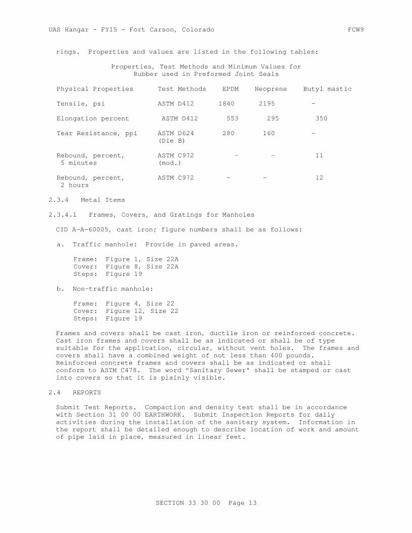
UAS Hangar - FY15 - Fort Carson, Colorado FCW9
rings. Properties and values are listed in the following tables:
Properties, Test Methods and Minimum Values forRubber used in Preformed Joint Seals
Physical Properties Test Methods EPDM Neoprene Butyl mastic
Tensile, psi ASTM D412 1840 2195 -
Elongation percent ASTM D412 553 295 350
Tear Resistance, ppi ASTM D624 280 160 - (Die B)
Rebound, percent, ASTM C972 - - 11 5 minutes (mod.)
Rebound, percent, ASTM C972 - - 12 2 hours
2.3.4 Metal Items
2.3.4.1 Frames, Covers, and Gratings for Manholes
CID A-A-60005, cast iron; figure numbers shall be as follows:
a. Traffic manhole: Provide in paved areas.
Frame: Figure 1, Size 22ACover: Figure 8, Size 22ASteps: Figure 19
b. Non-traffic manhole:
Frame: Figure 4, Size 22Cover: Figure 12, Size 22Steps: Figure 19
Frames and covers shall be cast iron, ductile iron or reinforced concrete. Cast iron frames and covers shall be as indicated or shall be of type suitable for the application, circular, without vent holes. The frames and covers shall have a combined weight of not less than 400 pounds. Reinforced concrete frames and covers shall be as indicated or shall conform to ASTM C478. The word "Sanitary Sewer" shall be stamped or cast into covers so that it is plainly visible.
2.4 REPORTS
Submit Test Reports. Compaction and density test shall be in accordance with Section 31 00 00 EARTHWORK. Submit Inspection Reports for daily activities during the installation of the sanitary system. Information in the report shall be detailed enough to describe location of work and amount of pipe laid in place, measured in linear feet.
SECTION 33 30 00 Page 13

UAS Hangar - FY15 - Fort Carson, Colorado FCW9
PART 3 EXECUTION
3.1 INSTALLATION OF PIPELINES AND APPURTENANT CONSTRUCTION
3.1.1 General Requirements for Installation of Pipelines
These general requirements apply except where specific exception is made in the following paragraphs entitled "Special Requirements."
3.1.1.1 Location
The work covered by this section shall terminate at a point approximately 5 feet from the building. Where the location of the sewer is not clearly defined by dimensions on the drawings, do not lay sewer line closer horizontally than 10 feet to a water main or service line. Install pressure sewer lines beneath water lines only, with the top of the sewer line being at least 2 feet below bottom of water line. Where sanitary sewer lines pass above water lines, encase sewer in concrete for a distance of 10 feet on each side of the crossing, or substitute rubber-gasketed pressure pipe for the pipe being used for the same distance. Where sanitary sewer lines pass below water lines, lay pipe so that no joint in the sewer line will be closer than 3 feet, horizontal distance, to the water line.
a. Sanitary piping installation parallel with water line:
(1) Normal conditions: Sanitary piping or manholes shall be laid at least 10 feet horizontally from a water line whenever possible. The distance shall be measured edge-to-edge.
(2) Unusual conditions: When local conditions prevent a horizontal separation of 10 feet, the sanitary piping or manhole may be laid closer to a water line provided that:
(a) The top (crown) of the sanitary piping shall be at least 18 inches below the bottom (invert) of the water main.
(b) Where this vertical separation cannot be obtained, the sanitary piping shall be constructed of AWWA-approved ductile iron water pipe pressure tested in place without leakage prior to backfilling.
(c) The sewer manhole shall be of watertight construction and tested in place.
b. Installation of sanitary piping crossing a water line:
(1) Normal conditions: Lay sanitary sewer piping by crossing under water lines to provide a separation of at least 18 inches between the top of the sanitary piping and the bottom of the water line whenever possible.
(2) Unusual conditions: When local conditions prevent a vertical separation described above, use the following construction:
(a) Sanitary piping passing over or under water lines shall be constructed of AWWA-approved ductile iron water pipe, pressure tested in place without leakage prior to backfilling.
(b) Sanitary piping passing over water lines shall, in addition,
SECTION 33 30 00 Page 14
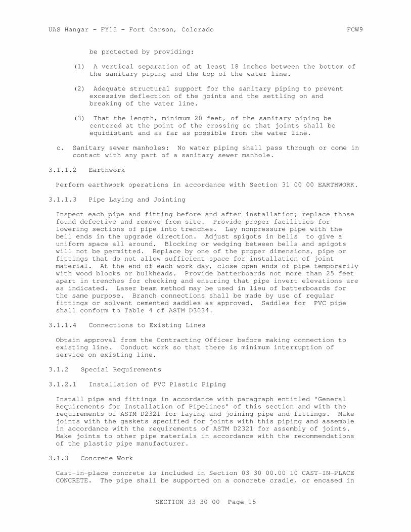
UAS Hangar - FY15 - Fort Carson, Colorado FCW9
be protected by providing:
(1) A vertical separation of at least 18 inches between the bottom of the sanitary piping and the top of the water line.
(2) Adequate structural support for the sanitary piping to prevent excessive deflection of the joints and the settling on and breaking of the water line.
(3) That the length, minimum 20 feet, of the sanitary piping be centered at the point of the crossing so that joints shall be equidistant and as far as possible from the water line.
c. Sanitary sewer manholes: No water piping shall pass through or come in contact with any part of a sanitary sewer manhole.
3.1.1.2 Earthwork
Perform earthwork operations in accordance with Section 31 00 00 EARTHWORK.
3.1.1.3 Pipe Laying and Jointing
Inspect each pipe and fitting before and after installation; replace those found defective and remove from site. Provide proper facilities for lowering sections of pipe into trenches. Lay nonpressure pipe with the bell ends in the upgrade direction. Adjust spigots in bells to give a uniform space all around. Blocking or wedging between bells and spigots will not be permitted. Replace by one of the proper dimensions, pipe or fittings that do not allow sufficient space for installation of joint material. At the end of each work day, close open ends of pipe temporarily with wood blocks or bulkheads. Provide batterboards not more than 25 feet apart in trenches for checking and ensuring that pipe invert elevations are as indicated. Laser beam method may be used in lieu of batterboards for the same purpose. Branch connections shall be made by use of regular fittings or solvent cemented saddles as approved. Saddles for PVC pipe shall conform to Table 4 of ASTM D3034.
3.1.1.4 Connections to Existing Lines
Obtain approval from the Contracting Officer before making connection to existing line. Conduct work so that there is minimum interruption of service on existing line.
3.1.2 Special Requirements
3.1.2.1 Installation of PVC Plastic Piping
Install pipe and fittings in accordance with paragraph entitled "General Requirements for Installation of Pipelines" of this section and with the requirements of ASTM D2321 for laying and joining pipe and fittings. Make joints with the gaskets specified for joints with this piping and assemble in accordance with the requirements of ASTM D2321 for assembly of joints. Make joints to other pipe materials in accordance with the recommendations of the plastic pipe manufacturer.
3.1.3 Concrete Work
Cast-in-place concrete is included in Section 03 30 00.00 10 CAST-IN-PLACE CONCRETE. The pipe shall be supported on a concrete cradle, or encased in
SECTION 33 30 00 Page 15

UAS Hangar - FY15 - Fort Carson, Colorado FCW9
concrete where indicated or directed.
3.1.4 Manhole Construction
Construct base slab of cast-in-place concrete or use precast concrete base sections. Make inverts in cast-in-place concrete and precast concrete bases with a smooth-surfaced semi-circular bottom conforming to the inside contour of the adjacent sewer sections. For changes in direction of the sewer and entering branches into the manhole, make a circular curve in the manhole invert of as large a radius as manhole size will permit. For cast-in-place concrete construction, either pour bottom slabs and walls integrally or key and bond walls to bottom slab. No parging will be permitted on interior manhole walls. For precast concrete construction, make joints between manhole sections with the gaskets specified for this purpose; install in the manner specified for installing joints in concrete piping. Parging will not be required for precast concrete manholes. Cast-in-place concrete work shall be in accordance with the requirements specified under paragraph entitled "Concrete Work" of this section. Make joints between concrete manholes and pipes entering manholes with the resilient connectors specified for this purpose; install in accordance with the recommendations of the connector manufacturer. Where a new manhole is constructed on an existing line, remove existing pipe as necessary to construct the manhole. Cut existing pipe so that pipe ends are approximately flush with the interior face of manhole wall, but not protruding into the manhole. Use resilient connectors as previously specified for pipe connectors to concrete manholes.
3.1.5 Miscellaneous Construction and Installation
3.1.5.1 Connecting to Existing Manholes
Pipe connections to existing manholes shall be made so that finish work will conform as nearly as practicable to the applicable requirements specified for new manholes, including all necessary concrete work, cutting, and shaping. The connection shall be centered on the manhole. Holes for the new pipe shall be of sufficient diameter to allow packing cement mortar around the entire periphery of the pipe but no larger than 1.5 times the diameter of the pipe. Cutting the manhole shall be done in a manner that will cause the least damage to the walls.
3.1.5.2 Metal Work
a. Workmanship and finish: Perform metal work so that workmanship and finish will be equal to the best practice in modern structural shops and foundries. Form iron to shape and size with sharp lines and angles. Do shearing and punching so that clean true lines and surfaces are produced. Make castings sound and free from warp, cold shuts, and blow holes that may impair their strength or appearance. Give exposed surfaces a smooth finish with sharp well-defined lines and arises. Provide necessary rabbets, lugs, and brackets wherever necessary for fitting and support.
b. Field painting: After installation, clean cast-iron frames, covers, gratings, and steps not buried in concrete to bare metal of mortar, rust, grease, dirt, and other deleterious materials and apply a coat of bituminous paint. Do not paint surfaces subject to abrasion.
SECTION 33 30 00 Page 16

UAS Hangar - FY15 - Fort Carson, Colorado FCW9
3.1.6 Installations of Wye Branches
Cutting into piping for connections shall not be done except in special approved cases. When the connecting pipe cannot be adequately supported on undisturbed earth or tamped backfill, the pipe shall be encased in concrete backfill or supported on a concrete cradle as directed. Concrete required because of conditions resulting from faulty construction methods or negligence shall be installed at no additional cost to the Government. The installation of wye branches in an existing sewer shall be made by a method which does not damage the integrity of the existing sewer. One acceptable method consists of removing one pipe section, breaking off the upper half of the bell of the next lower section and half of the running bell of wye section. After placing the new section, it shall be rotated so that the broken half of the bell will be at the bottom. The two joints shall then be made with joint packing and cement mortar.
3.2 FIELD QUALITY CONTROL
3.2.1 Field Tests and Inspections
The Contracting Officer will conduct field inspections and witness field tests specified in this section. Perform field tests and provide labor, equipment, and incidentals required for testing. Be able to produce evidence, when required, that each item of work has been constructed in accordance with the drawings and specifications.
3.2.2 Tests for Nonpressure Lines
Check each straight run of pipeline for gross deficiencies by holding a light in a manhole; it shall show a practically full circle of light through the pipeline when viewed from the adjoining end of line. When pressure piping is used in a nonpressure line for nonpressure use, test this piping as specified for nonpressure pipe.
3.2.2.1 Leakage Tests
Test lines for leakage by either infiltration tests or exfiltration tests, or by low-pressure air tests. Prior to testing for leakage, backfill trench up to at least lower half of pipe. When necessary to prevent pipeline movement during testing, place additional backfill around pipe sufficient to prevent movement, but leaving joints uncovered to permit inspection. When leakage or pressure drop exceeds the allowable amount specified, make satisfactory correction and retest pipeline section in the same manner. Correct visible leaks regardless of leakage test results.
a. Infiltration tests and exfiltration tests: Perform these tests for sewer lines made of the specified materials in accordance with ASTM C969. Make calculations in accordance with the Appendix to ASTM C969.
b. Low-pressure air tests: Perform tests as follows:
SECTION 33 30 00 Page 17

UAS Hangar - FY15 - Fort Carson, Colorado FCW9
(1) PVC plastic pipelines: Test in accordance with UBPPA UNI-B-6. Allowable pressure drop shall be as given in UBPPA UNI-B-6. Make calculations in accordance with the Appendix to UBPPA UNI-B-6.
3.2.2.2 Deflection Testing
Perform a deflection test on entire length of installed plastic pipeline on completion of work adjacent to and over the pipeline, including leakage tests, backfilling, placement of fill, grading, paving, concreting, and any other superimposed loads determined in accordance with ASTM D2412. Deflection of pipe in the installed pipeline under external loads shall not exceed 4.5 percent of the average inside diameter of pipe. Determine whether the allowable deflection has been exceeded by use of a pull-through device or a deflection measuring device.
a. Pull-through device: This device shall be a spherical, spheroidal, or elliptical ball, a cylinder, or circular sections fused to a common shaft. Circular sections shall be so spaced on the shaft that distance from external faces of front and back sections will equal or exceed diameter of the circular section. Pull-through device may also be of a design promulgated by the Uni-Bell Plastic Pipe Association, provided the device meets the applicable requirements specified in this paragraph, including those for diameter of the device, and that the mandrel has a minimum of 9 arms. Ball, cylinder, or circular sections shall conform to the following:
(1) A diameter, or minor diameter as applicable, of 95 percent of the average inside diameter of the pipe; tolerance of plus 0.5 percent will be permitted.
(2) Homogeneous material throughout, shall have a density greater than 1.0 as related to water at 39.2 degrees F, and shall have a surface Brinell hardness of not less than 150.
(3) Center bored and through-bolted with a 1/4 inch minimum diameter steel shaft having a yield strength of not less than 70,000 psi, with eyes or loops at each end for attaching pulling cables.
(4) Each eye or loop shall be suitably backed with a flange or heavy washer such that a pull exerted on opposite end of shaft will produce compression throughout remote end.
b. Deflection measuring device: Sensitive to 1.0 percent of the diameter of the pipe being tested and shall be accurate to 1.0 percent of the indicated dimension. Deflection measuring device shall be approved prior to use.
c. Pull-through device procedure: Pass the pull-through device through each run of pipe, either by pulling it through or flushing it through with water. If the device fails to pass freely through a pipe run, replace pipe which has the excessive deflection and completely retest in same manner and under same conditions.
d. Deflection measuring device procedure: Measure deflections through each run of installed pipe. If deflection readings in excess of 4.5 percent of average inside diameter of pipe are obtained, retest pipe by a run from the opposite direction. If retest continues to show a
SECTION 33 30 00 Page 18

UAS Hangar - FY15 - Fort Carson, Colorado FCW9
deflection in excess of 4.5 percent of average inside diameter of pipe, replace pipe which has excessive deflection and completely retest in same manner and under same conditions.
3.2.3 Tests for Pressure Lines
Test pressure lines in accordance with the applicable standard specified in this paragraph, except for test pressures. For hydrostatic pressure test, use a hydrostatic pressure 50 psi in excess of the maximum working pressure of the system, but not less than 100 psi, holding the pressure for a period of not less than one hour. For leakage test, use a hydrostatic pressure not less than the maximum working pressure of the system. Leakage test may be performed at the same time and at the same test pressure as the pressure test. Test PVC plastic pressure lines in accordance with the requirements of AWWA C605 for pressure and leakage tests, using the allowable leakage given therein.
3.2.4 Field Tests for Concrete
Field testing requirements are covered in Section 03 30 00.00 10 CAST-IN-PLACE CONCRETE
-- End of Section --
SECTION 33 30 00 Page 19

This page was intentionally left blank for duplex printing.
UAS Hangar - FY15 - Fort Carson, Colorado FCW9
SECTION TABLE OF CONTENTS
DIVISION 33 - UTILITIES
SECTION 33 40 01
STORM DRAINAGE
03/10
PART 1 GENERAL
1.1 REFERENCES 1.2 SUBMITTALS 1.3 DELIVERY, STORAGE, AND HANDLING 1.3.1 Delivery and Storage 1.3.2 Handling 1.4 DEFINITIONS 1.4.1 Degree of Compaction
PART 2 PRODUCTS
2.1 PIPE FOR CULVERTS AND STORM DRAINS 2.1.1 Reinforced Concrete Pipe 2.1.2 PVC Pipe 2.1.2.1 Type PSM PVC Pipe 2.1.2.2 Profile PVC Pipe 2.1.2.3 Smooth Wall PVC Pipe 2.1.2.4 Corrugated PVC Pipe 2.1.3 PE Pipe 2.1.3.1 Smooth Wall PE Pipe 2.1.3.2 Corrugated PE Pipe 2.1.3.3 Profile Wall PE Pipe 2.2 PIPE FOR ROOF DRAINS 2.2.1 PVC Pipe 2.2.1.1 Type PSM PVC Pipe 2.2.1.2 Profile PVC Pipe 2.2.1.3 Corrugated PVC Pipe 2.2.2 Corrugated PE Pipe 2.3 PIPE JOINTS 2.3.1 Concrete Pipe 2.3.1.1 Rubber Gasket Joints 2.3.2 PVC Plastic Pipe 2.3.3 Smooth Wall PE Plastic Pipe 2.3.4 Corrugated PE Plastic Pipe 2.3.5 Profile Wall PE Plastic Pipe 2.4 DRAINAGE STRUCTURES 2.4.1 Precast Reinforced Concrete Manholes 2.4.2 Reinforced Concrete Inlets and Headwalls 2.4.3 Flared End Sections 2.5 FRAME AND COVER OR GRATINGS 2.6 DOWNSPOUT BOOTS 2.7 RESILIENT CONNECTORS 2.8 MISCELLANEOUS MATERIALS 2.8.1 Concrete 2.8.2 Mortar
SECTION 33 40 01 Page 1

UAS Hangar - FY15 - Fort Carson, Colorado FCW9
PART 3 EXECUTION
3.1 EXCAVATION FOR PIPE CULVERTS, STORM DRAINS, AND DRAINAGE STRUCTURES 3.1.1 Trenching 3.1.2 Removal of Rock 3.1.3 Removal of Unstable Material 3.2 PIPE BEDDING AND INITIAL BACKFILL 3.2.1 Concrete Pipe Requirements 3.2.2 Plastic Pipe 3.3 PLACING PIPE 3.3.1 Concrete, PVC, and Ribbed PVC Pipe 3.3.2 Corrugated PE Pipe 3.3.3 Jacking Pipe Through Fills 3.4 JOINTING 3.4.1 Concrete Pipe 3.4.1.1 Rubber Gasket Joints 3.5 TRACER WIRE AND WARNING TAPE INSTALLATION 3.6 FINAL BACKFILL 3.7 DRAINAGE STRUCTURES 3.7.1 Manholes and Inlets 3.7.2 Headwalls 3.8 HYDROSTATIC TEST ON WATERTIGHT JOINTS 3.8.1 Concrete, PVC and PE Pipe 3.9 PIPELINE TESTING 3.9.1 Deflection Testing
-- End of Section Table of Contents --
SECTION 33 40 01 Page 2

UAS Hangar - FY15 - Fort Carson, Colorado FCW9
SECTION 33 40 01
STORM DRAINAGE03/10
PART 1 GENERAL
1.1 REFERENCES
The publications listed below form a part of this specification to the extent referenced. The publications are referred to in the text by the basic designation only.
ACI INTERNATIONAL (ACI)
ACI 346 (2009) Specification for Cast-in-Place Concrete Pipe
AMERICAN ASSOCIATION OF STATE HIGHWAY AND TRANSPORTATION OFFICIALS (AASHTO)
AASHTO HB-17 (2002; Errata 2003; Errata 2005, 17th Edition) Standard Specifications for Highway Bridges
AASHTO M 190 (2004; R 2008) Standard Specification for Bituminous Coated Corrugated Metal Culvert Pipe and Pipe Arches
AASHTO M 198 (2010) Standard Specification for Joints for Concrete Pipe, Manholes, and Precast Box Sections Using Preformed Flexible Joint Sealants
AASHTO M 243 (1996; R 2008) Standard Specification for Field-Applied Coating of Corrugated Metal Structural Plate for Pipe, Pipe-Arches, and Arches
AASHTO M 252 (2009) Standard Specification for Corrugated Polyethylene Drainage Pipe
AASHTO M 252M (1996) Corrugated Polyethylene Drainage Tubing
AASHTO M 294 (2011) Standard Specification for Corrugated Polyethylene Pipe, 300- to 1500-mm Diameter
AASHTO M 306 (2010) Standard Specification for Drainage, Sewer, Utility, and Related Castings
AASHTO T 180 (2010) Standard Method of Test for Moisture-Density Relations of Soils Using a 4.54-kg (10-lb) Rammer and a 457-mm
SECTION 33 40 01 Page 3

UAS Hangar - FY15 - Fort Carson, Colorado FCW9
(18-in.) Drop
AASHTO T 224 (2010) Standard Method of Test for Correction for Coarse Particles in the Soil Compaction Test
AMERICAN RAILWAY ENGINEERING AND MAINTENANCE-OF-WAY ASSOCIATION (AREMA)
AREMA Eng Man (2010) Manual for Railway Engineering
AMERICAN WATER WORKS ASSOCIATION (AWWA)
AWWA C110/A21.10 (2008) Ductile-Iron and Gray-Iron Fittings for Water
AWWA C111/A21.11 (2007) Rubber-Gasket Joints for Ductile-Iron Pressure Pipe and Fittings
AWWA C153/A21.53 (2011) Ductile-Iron Compact Fittings for Water Service
ASTM INTERNATIONAL (ASTM)
ASTM A48/A48M (2003; R 2012) Standard Specification for Gray Iron Castings
ASTM A123/A123M (2009) Standard Specification for Zinc (Hot-Dip Galvanized) Coatings on Iron and Steel Products
ASTM A615/A615M (2009b) Standard Specification for Deformed and Plain Carbon-Steel Bars for Concrete Reinforcement
ASTM A706/A706M (2009b) Standard Specification for Low-Alloy Steel Deformed and Plain Bars for Concrete Reinforcement
ASTM A746 (2009) Standard Specification for Ductile Iron Gravity Sewer Pipe
ASTM A742/A742M (2003; R 2008) Standard Specification for Steel Sheet, Metallic Coated and Polymer Precoated for Corrugated Steel Pipe
ASTM A760/A760M (2010) Standard Specification for Corrugated Steel Pipe, Metallic-Coated for Sewers and Drains
ASTM A762/A762M (2008) Standard Specification for Corrugated Steel Pipe, Polymer Precoated for Sewers and Drains
ASTM A798/A798M (2007) Standard Practice for Installing Factory-Made Corrugated Steel Pipe for Sewers and Other Applications
ASTM A849 (2010) Standard Specification for
SECTION 33 40 01 Page 4

UAS Hangar - FY15 - Fort Carson, Colorado FCW9
Post-Applied Coatings, Pavings, and Linings for Corrugated Steel Sewer and Drainage Pipe
ASTM A929/A929M (2001; R 2007) Standard Specification for Steel Sheet, Metallic-Coated by the Hot-Dip Process for Corrugated Steel Pipe
ASTM B745/B745M (1997; R 2005) Standard Specification for Corrugated Aluminum Pipe for Sewers and Drains
ASTM C12 (2009) Standard Practice for Installing Vitrified Clay Pipe Lines
ASTM C14 (2011) Standard Specification for Concrete Sewer, Storm Drain, and Culvert Pipe
ASTM C14M (2011) Standard Specification for Concrete Sewer, Storm Drain, and Culvert Pipe (Metric)
ASTM C39/C39M (2011) Standard Test Method for Compressive Strength of Cylindrical Concrete Specimens
ASTM C76 (2011) Standard Specification for Reinforced Concrete Culvert, Storm Drain, and Sewer Pipe
ASTM C76M (2011) Standard Specification for Reinforced Concrete Culvert, Storm Drain, and Sewer Pipe (Metric)
ASTM C231/C231M (2010) Standard Test Method for Air Content of Freshly Mixed Concrete by the Pressure Method
ASTM C270 (2012a) Standard Specification for Mortar for Unit Masonry
ASTM C425 (2004; R 2009) Standard Specification for Compression Joints for Vitrified Clay Pipe and Fittings
ASTM C443 (2011) Standard Specification for Joints for Concrete Pipe and Manholes, Using Rubber Gaskets
ASTM C443M (2011) Standard Specification for Joints for Concrete Pipe and Manholes, Using Rubber Gaskets (Metric)
ASTM C478 (2013) Standard Specification for Precast Reinforced Concrete Manhole Sections
ASTM C478M (2009) Standard Specification for Precast Reinforced Concrete Manhole Sections (Metric)
SECTION 33 40 01 Page 5
UAS Hangar - FY15 - Fort Carson, Colorado FCW9
ASTM C506 (2011) Standard Specification for Reinforced Concrete Arch Culvert, Storm Drain, and Sewer Pipe
ASTM C506M (2011) Standard Specification for Reinforced Concrete Arch Culvert, Storm Drain, and Sewer Pipe (Metric)
ASTM C507 (2011) Standard Specification for Reinforced Concrete Elliptical Culvert, Storm Drain, and Sewer Pipe
ASTM C507M (2011) Standard Specification for Reinforced Concrete Elliptical Culvert, Storm Drain, and Sewer Pipe (Metric)
ASTM C655 (2011) Reinforced Concrete D-Load Culvert, Storm Drain, and Sewer Pipe
ASTM C700 (2011) Standard Specification for Vitrified Clay Pipe, Extra Strength, Standard Strength, and Perforated
ASTM C828 (2011) Low-Pressure Air Test of Vitrified Clay Pipe Lines
ASTM C94/C94M (2011b) Standard Specification for Ready-Mixed Concrete
ASTM C923 (2008; R 2013) Standard Specification for Resilient Connectors Between Reinforced Concrete Manhole Structures, Pipes and Laterals
ASTM C923M (2008b) Standard Specification for Resilient Connectors Between Reinforced Concrete Manhole Structures, Pipes and Laterals (Metric)
ASTM C924 (2002; R 2009) Testing Concrete Pipe Sewer Lines by Low-Pressure Air Test Method
ASTM C924M (2002; R 2009) Testing Concrete Pipe Sewer Liner by Low-Pressure Air Test Method (Metric)
ASTM C990 (2009) Standard Specification for Joints for Concrete Pipe, Manholes and Precast Box Sections Using Preformed Flexible Joint Sealants
ASTM C1103 (2003; R 2009) Standard Practice for Joint Acceptance Testing of Installed Precast Concrete Pipe Sewer Lines
ASTM C1103M (2003; R 2009) Standard Practice for Joint Acceptance Testing of Installed Precast Concrete Pipe Sewer Lines (Metric)
SECTION 33 40 01 Page 6
UAS Hangar - FY15 - Fort Carson, Colorado FCW9
ASTM C1433 (2010) Standard Specification for Precast Reinforced Concrete Box Sections for Culverts, Storm Drains, and Sewers
ASTM C1433M (2010) Standard Specification for Precast Reinforced Concrete Box Sections for Culverts, Storm Drains, and Sewers (Metric)
ASTM D1056 (2007) Standard Specification for Flexible Cellular Materials - Sponge or Expanded Rubber
ASTM D1171 (1999; R 2007) Rubber Deterioration - Surface Ozone Cracking Outdoors or Chamber (Triangular Specimens)
ASTM D1557 (2012) Standard Test Methods for Laboratory Compaction Characteristics of Soil Using Modified Effort (56,000 ft-lbf/ft3) (2700 kN-m/m3)
ASTM D1784 (2011) Standard Specification for Rigid Poly(Vinyl Chloride) (PVC) Compounds and Chlorinated Poly(Vinyl Chloride) (CPVC) Compounds
ASTM D2321 (2011) Standard Practice for Underground Installation of Thermoplastic Pipe for Sewers and Other Gravity-Flow Applications
ASTM D2487 (2011) Soils for Engineering Purposes (Unified Soil Classification System)
ASTM D3034 (2008) Standard Specification for Type PSM Poly(Vinyl Chloride) (PVC) Sewer Pipe and Fittings
ASTM D3212 (2007; R 2013) Standard Specification for Joints for Drain and Sewer Plastic Pipes Using Flexible Elastomeric Seals
ASTM D3350 (2010a) Polyethylene Plastics Pipe and Fittings Materials
ASTM D4586 (2007/2012) Asphalt Roof Cement, Asbestos-Free
ASTM F477 (2010) Standard Specification for Elastomeric Seals (Gaskets) for Joining Plastic Pipe
ASTM F679 (2008) Poly(Vinyl Chloride) (PVC) Large-Diameter Plastic Gravity Sewer Pipe and Fittings
ASTM F714 (2010) Polyethylene (PE) Plastic Pipe (SDR-PR) Based on Outside Diameter
SECTION 33 40 01 Page 7

UAS Hangar - FY15 - Fort Carson, Colorado FCW9
ASTM F794 (2003; R 2009) Standard Specification for Poly(Vinyl Chloride) (PVC) Profile Gravity Sewer Pipe and Fittings Based on Controlled Inside Diameter
ASTM F894 (2007) Polyethylene (PE) Large Diameter Profile Wall Sewer and Drain Pipe
ASTM F949 (2010) Poly(Vinyl Chloride) (PVC) Corrugated Sewer Pipe with a Smooth Interior and Fittings
ASTM F1417 (2011a) Standard Test Method for Installation Acceptance of Plastic Gravity Sewer Lines Using Low Pressure Air
1.2 SUBMITTALS
Government approval is required for submittals with a "G" designation; submittals not having a "G" designation are for information only or as otherwise designated. When used, a designation following the "G" designation identifies the office that will review the submittal for the Government. The following shall be submitted in accordance with Section 01 33 00 SUBMITTAL PROCEDURES:
SD-03 Product Data
Placing Pipe
Printed copies of the manufacturer's recommendations for installation procedures of the material being placed, prior to installation.
SD-07 Certificates
Resin CertificationHydrostatic Test on Watertight JointsPipeline TestingDeflection Testing
Certified copies of test reports demonstrating conformance to applicable pipe specifications, before pipe is installed.
1.3 DELIVERY, STORAGE, AND HANDLING
1.3.1 Delivery and Storage
Materials delivered to site shall be inspected for damage, unloaded, and stored with a minimum of handling. Materials shall not be stored directly on the ground. The inside of pipes and fittings shall be kept free of dirt and debris. Before, during, and after installation, plastic pipe and fittings shall be protected from any environment that would result in damage or deterioration to the material. The Contractor shall have a copy of the manufacturer's instructions available at the construction site at all times and shall follow these instructions unless directed otherwise by the Contracting Officer. Solvents, solvent compounds, lubricants, elastomeric gaskets, and any similar materials required to install plastic pipe shall be stored in accordance with the manufacturer's recommendations and shall be discarded if the storage period exceeds the recommended shelf
SECTION 33 40 01 Page 8

UAS Hangar - FY15 - Fort Carson, Colorado FCW9
life. Solvents in use shall be discarded when the recommended pot life is exceeded.
1.3.2 Handling
Materials shall be handled in a manner that ensures delivery to the trench in sound, undamaged condition. Pipe shall be carried to the trench, not dragged.
1.4 DEFINITIONS
1.4.1 Degree of Compaction
Degree of compaction is a percentage of the laboatory maximum density obtained by the test procedure presented in either ASTM D1557 or AASHTO T 180 Method D and corrected with AASHTO T 224. The maximum density shall be determined in accordance with ASTM D1557 if the soils have 30 percent or less by weight retained on the 3/4 inch sieve or AASHTO T 180 and AASHTO T 224 if the soils have more than 30 percent by weight retained on the 3/4 inch sieve.
PART 2 PRODUCTS
2.1 PIPE FOR CULVERTS AND STORM DRAINS
Pipe for culverts and storm drains shall be of the sizes indicated and shall conform to the requirements specified.
2.1.1 Reinforced Concrete Pipe
Round pipe shall conform to ASTM C76, Class as indicated in the drawings. Portland cement used to manufacture pipe shall be Type II (low-alkali) or Type V (low-alkali).
2.1.2 PVC Pipe
The pipe manufacturer's resin certification, indicating the cell classification of PVC used to manufacture the pipe, shall be submitted prior to installation of the pipe.
2.1.2.1 Type PSM PVC Pipe
ASTM D3034, Type PSM, maximum SDR 35, produced from PVC certified by the compounder as meeting the requirements of ASTM D1784, minimum cell class 12454-B.
2.1.2.2 Profile PVC Pipe
ASTM F794, Series 46, produced from PVC certified by the compounder as meeting the requirements of ASTM D1784, minimum cell class 12454-B.
2.1.2.3 Smooth Wall PVC Pipe
ASTM F679 produced from PVC certified by the compounder as meeting the requirements of ASTM D1784, minimum cell class 12454-B.
2.1.2.4 Corrugated PVC Pipe
ASTM F949 produced from PVC certified by the compounder as meeting the
SECTION 33 40 01 Page 9
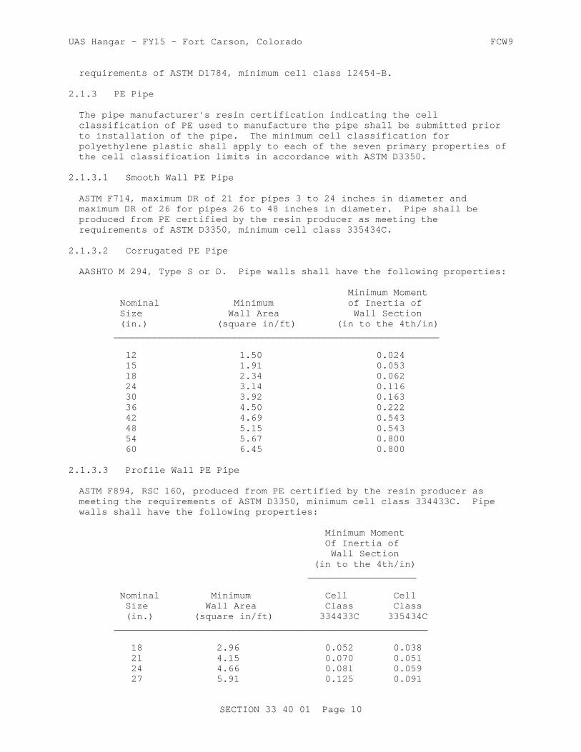
UAS Hangar - FY15 - Fort Carson, Colorado FCW9
requirements of ASTM D1784, minimum cell class 12454-B.
2.1.3 PE Pipe
The pipe manufacturer's resin certification indicating the cell classification of PE used to manufacture the pipe shall be submitted prior to installation of the pipe. The minimum cell classification for polyethylene plastic shall apply to each of the seven primary properties of the cell classification limits in accordance with ASTM D3350.
2.1.3.1 Smooth Wall PE Pipe
ASTM F714, maximum DR of 21 for pipes 3 to 24 inches in diameter and maximum DR of 26 for pipes 26 to 48 inches in diameter. Pipe shall be produced from PE certified by the resin producer as meeting the requirements of ASTM D3350, minimum cell class 335434C.
2.1.3.2 Corrugated PE Pipe
AASHTO M 294, Type S or D. Pipe walls shall have the following properties:
Minimum Moment Nominal Minimum of Inertia of Size Wall Area Wall Section (in.) (square in/ft) (in to the 4th/in) _________________________________________________________
12 1.50 0.024 15 1.91 0.053 18 2.34 0.062 24 3.14 0.116 30 3.92 0.163 36 4.50 0.222 42 4.69 0.543 48 5.15 0.543 54 5.67 0.800 60 6.45 0.800
2.1.3.3 Profile Wall PE Pipe
ASTM F894, RSC 160, produced from PE certified by the resin producer as meeting the requirements of ASTM D3350, minimum cell class 334433C. Pipe walls shall have the following properties:
Minimum Moment Of Inertia of Wall Section (in to the 4th/in) ___________________
Nominal Minimum Cell Cell Size Wall Area Class Class (in.) (square in/ft) 334433C 335434C _______________________________________________________
18 2.96 0.052 0.038 21 4.15 0.070 0.051 24 4.66 0.081 0.059 27 5.91 0.125 0.091
SECTION 33 40 01 Page 10

UAS Hangar - FY15 - Fort Carson, Colorado FCW9
Minimum Moment Of Inertia of Wall Section (in to the 4th/in) ___________________
Nominal Minimum Cell Cell Size Wall Area Class Class (in.) (square in/ft) 334433C 335434C _______________________________________________________ 30 5.91 0.125 0.091 33 6.99 0.161 0.132 36 8.08 0.202 0.165 42 7.81 0.277 0.227 48 8.82 0.338 0.277
2.2 PIPE FOR ROOF DRAINS
2.2.1 PVC Pipe
The pipe manufacturer's resin certification, indicating the cell classification of PVC used to manufacture the pipe, shall be submitted prior to installation of the pipe.
2.2.1.1 Type PSM PVC Pipe
ASTM D3034, Type PSM, maximum SDR 35, produced from PVC certified by the compounder as meeting the requirements of ASTM D1784, minimum cell class 12454-B.
2.2.1.2 Profile PVC Pipe
ASTM F794, Series 46, produced from PVC certified by the compounder as meeting the requirements of ASTM D1784, minimum cell class 12454-B.
2.2.1.3 Corrugated PVC Pipe
ASTM F949 produced from PVC certified by the compounder as meeting the requirements of ASTM D1784, minimum cell class 12454-B.
2.2.2 Corrugated PE Pipe
AASHTO M 252, Type S.
2.3 PIPE JOINTS
Joints for storm drain pipes shall be tested and shall meet the test requirements of paragraph HYDROSTATIC TEST ON WATERTIGHT JOINTS. Roof drain pipes shall be exempt from this test.
2.3.1 Concrete Pipe
2.3.1.1 Rubber Gasket Joints
The design of joints and the physical requirements for rubber gaskets shall conform to ASTM C443. Certified copies of test results shall be delivered to the Contracting Officer before gaskets or jointing materials are installed. Gaskets shall have not more than one factory-fabricated
SECTION 33 40 01 Page 11
UAS Hangar - FY15 - Fort Carson, Colorado FCW9
splice, except that two factory-fabricated splices of the rubber-type gasket are permitted if the nominal diameter of the pipe being gasketed exceeds 54 inches.
2.3.2 PVC Plastic Pipe
Joints shall be solvent cement or elastomeric gasket type in accordance with the specification for the pipe and as recommended by the pipe manufacturer.
2.3.3 Smooth Wall PE Plastic Pipe
Pipe shall be joined using butt fusion method as recommended by the pipe manufacturer.
2.3.4 Corrugated PE Plastic Pipe
Joints shall be integral bell and spigot type with rubber gasket. Rubber gaskets shall conform to ASTM F477. Joints shall be water tight conforming to AASHTO M 294. Watertight joints shall meet the requirements of Paragraph HYDROSTATIC TEST ON WATERTIGHT JOINTS.
2.3.5 Profile Wall PE Plastic Pipe
Joints shall be gasketed or thermal weld type with integral bell in accordance with ASTM F894.
2.4 DRAINAGE STRUCTURES
2.4.1 Precast Reinforced Concrete Manholes
Precast reinforced concrete manholes shall conform to ASTM C478. Joints between precast concrete risers and tops shall be made with flexible watertight, rubber-type gaskets meeting the requirements of paragraph JOINTS.
2.4.2 Reinforced Concrete Inlets and Headwalls
Concrete for inlets and headwalls shall conform to paragraph: CONCRETE. Reinforcing steel shall be deformed bars conforming to Section 03 20 00.00 10 CONCRETE REINFORCEMENT , grades and sizes as indicated.
2.4.3 Flared End Sections
Concrete flared end sections shall conform to the manufacturer's standard design.
2.5 FRAME AND COVER OR GRATINGS
Frame and cover or gratings shall be either cast gray iron or cast ductile iron conforming to AASHTO M 306. Weight, shape, size, and waterway openings for grates and curb inlets shall be as indicated on the plans.
2.6 DOWNSPOUT BOOTS
Boots used to connect exterior downspouts to the storm-drainage system shall be of gray cast iron conforming to ASTM A48/A48M, Class 30B or 35B. Shape and size shall be as indicated.
SECTION 33 40 01 Page 12
UAS Hangar - FY15 - Fort Carson, Colorado FCW9
2.7 RESILIENT CONNECTORS
Flexible, watertight connectors used for connecting pipe to manholes and inlets shall conform to ASTM C923.
2.8 MISCELLANEOUS MATERIALS
2.8.1 Concrete
Unless otherwise specified, concrete and reinforced concrete shall conform to the requirements for 4000 psi concrete under Section 03 30 00.00 10 CAST-IN-PLACE STRUCTURAL CONCRETE The concrete mixture shall be air entrained to contain between 4 and 7 percent total air, except that when the nominal maximum size of coarse aggregate is 3/4 inch or smaller, it shall have between 4.5 and 7.5 percent. Air content shall be determined in accordance with ASTM C231/C231M. The concrete covering over steel reinforcing shall not be less than 1-1/2 inches thick for walls and flooring. Concrete covering deposited directly against the ground shall have a thickness of at least 3 inches between steel and ground.
2.8.2 Mortar
Mortar for pipe connections to drainage structures shall conform to ASTM C270, Type M, except that the maximum placement time shall be 1 hour. The quantity of water in the mixture shall be sufficient to produce a stiff workable mortar but in no case shall exceed 5 gallons of water per sack of cement. Water shall be clean and free of harmful acids, alkalies, and organic impurities. The mortar shall be used within 30 minutes after the ingredients are mixed with water. The inside of the joint shall be wiped clean and finished smooth. The mortar head on the outside shall be protected from air and sun with a proper covering until satisfactorily cured.
PART 3 EXECUTION
3.1 EXCAVATION FOR PIPE CULVERTS, STORM DRAINS, AND DRAINAGE STRUCTURES
Excavation of trenches, and for appurtenances and backfilling for culverts and storm drains, shall be in accordance with the applicable portions of Section 31 00 00 EARTHWORK and the requirements specified below.
3.1.1 Trenching
The width of trenches at any point below the top of the pipe shall be not greater than required to permit satisfactory jointing and thorough tamping of the bedding material under and around the pipe. Where trench widths are exceeded, redesign with a resultant increase in cost of stronger pipe or special installation procedures will be necessary. Cost of this redesign and increased cost of pipe or installation shall be borne by the Contractor without additional cost to the Government.
3.1.2 Removal of Rock
Rock in either ledge or boulder formation shall be replaced with suitable materials to provide a compacted earth cushion having a thickness between unremoved rock and the pipe of at least 8 inches or 1/2 inch for each foot of fill over the top of the pipe, whichever is greater, but not more than three-fourths the nominal diameter of the pipe. Where bell-and-spigot pipe is used, the cushion shall be maintained under the bell as well as under
SECTION 33 40 01 Page 13

UAS Hangar - FY15 - Fort Carson, Colorado FCW9
the straight portion of the pipe. Suitable material shall be compacted to at least 90 percent of laboratory maximum desity for cohesive soils and 95 percent of laboratory maximum density for cohesionless soils. Rock excavation shall be as specified and defined in Section 31 00 00 EARTHWORK.
3.1.3 Removal of Unstable Material
Where wet or otherwise unstable soil incapable of properly supporting the pipe, as determined by the Contracting Officer, is unexpectedly encountered in the bottom of a trench, such material shall be removed to the depth required and replaced to the proper grade with select granular material, compacted as provided in paragraph BACKFILLING. When removal of unstable material is due to the fault or neglect of the Contractor while performing shoring and sheeting, water removal, or other specified requirements, such removal and replacement shall be performed at no additional cost to the Government.
3.2 PIPE BEDDING AND INITIAL BACKFILL
The bedding surface for the pipe shall provide a firm foundation of uniform density throughout the entire length of the pipe.
3.2.1 Concrete Pipe Requirements
When no bedding class is specified or detailed on the drawings, concrete pipe shall be bedded in granular material minimum 4 inch in depth in trenches with soil foundation. Depth of granular bedding in trenches with rock foundation shall be 1/2 inch in depth per foot of depth of fill, minimum depth of bedding shall be 8 inch up to maximum depth of 24 inches. The middle third of the granular bedding shall be loosely placed. Bell holes and depressions for joints shall be removed and formed so entire barrel of pipe is uniformly supported. The bell hole and depressions for the joints shall be not more than the length, depth, and width required for properly making the particular type of joint.
3.2.2 Plastic Pipe
Bedding for PVC and PE pipe shall meet the requirements of ASTM D2321. Bedding, haunching, and initial backfill shall be either Class I or II material.
3.3 PLACING PIPE
Each pipe shall be thoroughly examined before being laid; defective or damaged pipe shall not be used. Plastic pipe shall be protected from exposure to direct sunlight prior to laying, if necessary to maintain adequate pipe stiffness and meet installation deflection requirements. Pipelines shall be laid to the grades and alignment indicated. Proper facilities shall be provided for lowering sections of pipe into trenches. Pipe shall not be laid in water, and pipe shall not be laid when trench conditions or weather are unsuitable for such work. Diversion of drainage or dewatering of trenches during construction shall be provided as necessary. Deflection of installed flexible pipe shall not exceed the following limits:
SECTION 33 40 01 Page 14

UAS Hangar - FY15 - Fort Carson, Colorado FCW9
MAXIMUM ALLOWABLE TYPE OF PIPE DEFLECTION (%)
Plastic 5
Not less than 30 days after the completion of backfilling, the Government may perform a deflection test on the entire length of installed flexible pipe using a mandrel or other suitable device. Installed flexible pipe showing deflections greater than those indicated above shall be retested by a run from the opposite direction. If the retest also fails, the suspect pipe shall be replaced.
3.3.1 Concrete, PVC, and Ribbed PVC Pipe
Laying shall proceed upgrade with spigot ends of bell-and-spigot pipe and tongue ends of tongue-and-groove pipe pointing in the direction of the flow.
3.3.2 Corrugated PE Pipe
Laying shall be with the separate sections joined firmly on a bed shaped to line and grade and shall follow manufacturer's recommendations.
3.3.3 Jacking Pipe Through Fills
Methods of operation and installation for jacking pipe through fills shall conform to requirements specified in Volume 1, Chapter 1, Part 4 of AREMA Eng Man.
3.4 JOINTING
3.4.1 Concrete Pipe
3.4.1.1 Rubber Gasket Joints
Gaskets and jointing materials shall be as recommended by the particular manufacturer in regard to use of lubricants, cements, adhesives, and other special installation requirements. Surfaces to receive lubricants, cements, or adhesives shall be clean and dry. Gaskets and jointing materials shall be affixed to the pipe not more than 24 hours prior to the installation of the pipe, and shall be protected from the sun, blowing dust, and other deleterious agents at all times. Gaskets and jointing materials shall be inspected before installing the pipe; any loose or improperly affixed gaskets and jointing materials shall be removed and replaced. The pipe shall be aligned with the previously installed pipe, and the joint pushed home. If, while the joint is being made the gasket becomes visibly dislocated the pipe shall be removed and the joint remade.
3.5 TRACER WIRE AND WARNING TAPE INSTALLATION
Tracer wire shall be installed above all non-metallic storm drain pipe and roof drain pipe in accordance with Section 31 00 00 EARTHWORK and the drawings. Warning tape shall be installed above all storm drain and roof drain pipe in accordance with Section 31 00 00 EARTHWORK.
SECTION 33 40 01 Page 15

UAS Hangar - FY15 - Fort Carson, Colorado FCW9
3.6 FINAL BACKFILL
The final backfill shall consist of satisfactory material deposited in layers of a maximum of 8 inch loose thickness and compacted to 90 percent of maximum density for cohesive soils and 95 percent of maximum density for cohesionless soils in accordance with Section 31 00 00 EARTHWORK. When compacting by rolling or operating heavy equipment parallel with the pipe, displacement of or injury to the pipe shall be avoided. Movement of construction machinery over a culvert or storm drain at any stage of construction shall be at the Contractor's risk. Any damaged pipe shall be repaired or replaced. Concrete pipes shall be protected by a minimum of 3 feet of cover prior to permitting heavy construction equipment to pass over them during construction. Minimum cover for construction loads over corrugated steel pipes shall be as specified in Section 26, Division II of AASHTO HB-17. Minimum cover for construction loads over plastic pipes shall be as specified in ASTM D2321.
3.7 DRAINAGE STRUCTURES
3.7.1 Manholes and Inlets
Construction shall be of cast-in-place or precast reinforced concrete; complete with frames and covers or gratings. Pipe connections to concrete manholes and inlets shall be made with flexible, watertight connectors.
3.7.2 Headwalls
Construction shall be as indicated.
3.8 HYDROSTATIC TEST ON WATERTIGHT JOINTS
A hydrostatic test shall be made on the watertight joint types as proposed. Only one sample joint of each type needs testing; however, if the sample joint fails because of faulty design or workmanship, an additional sample joint may be tested. During the test period, gaskets or other jointing material shall be protected from extreme temperatures which might adversely affect the performance of such materials.
3.8.1 Concrete, PVC and PE Pipe
Watertight joints in reinforced concrete pipe shall conform to AASHTO M 198 or ASTM C443. Test requirements for joints in PVC and PE plastic pipe shall conform to ASTM D3212.
3.9 PIPELINE TESTING
3.9.1 Deflection Testing
Perform a deflection test on entire length of installed plastic pipeline on completion of work adjacent to and over the pipeline, including leakage tests, backfilling, placement of fill, grading, paving, concreting, and any other superimposed loads. Deflection of pipe in the installed pipeline under external loads shall not exceed 4.5 percent of the average inside diameter of pipe. Determine whether the allowable deflection has been exceeded by use of a pull-through device or a deflection measuring device.
a. Pull-through device: This device shall be a spherical, spheroidal, or elliptical ball, a cylinder, or circular sections fused to a common shaft. Circular sections shall be so spaced on
SECTION 33 40 01 Page 16

UAS Hangar - FY15 - Fort Carson, Colorado FCW9
the shaft that distance from external faces of front and back sections will equal or exceed diameter of the circular section. Pull-through device may also be of a design promulgated by the Uni-Bell Plastic Pipe Association, provided that the device meets the applicable requirements specified in this paragraph, including those for diameter of the device. Ball, cylinder, or circular sections shall conform to the following:
(1) A diameter, or minor diameter as applicable, of 95 percent of the average inside diameter of the pipe; tolerance of plus 0.5 percent will be permitted.
(2) A homogeneous material throughout, with a density greater than 1.0 as related to water at 39.2 degrees F, and a surface Brinell hardness of not less than 150.
(3) Center bored and through bolted with a 1/4 inch minimum diameter steel shaft having a yield strength of not less than 70,000 psi, with eyes or loops at each end for attaching pulling cables.
(4) Each eye or loop shall be suitably backed with a flange or heavy washer such that a pull exerted on opposite end of shaft will produce compression throughout remote end.
b. Deflection measuring device: Sensitive to 1.0 percent of the diameter of the pipe being tested and accurate to 1.0 percent of the indicated dimension. Deflection measuring device shall be approved by the Contracting Officer prior to use.
c. Pull-through device: Pass the pull-through device through each run of pipe, either by pulling it through or flushing it through with water. If the device fails to pass freely through a pipe run, replace pipe which has the excessive deflection and completely retest in same manner and under same conditions as specified.
d. Deflection measuring device procedure: Measure deflections through each run of installed pipe. If deflection readings in excess of 4.5 percent of average inside diameter of pipe are obtained, retest pipe by a run from the opposite direction. If retest continues to show a deflection in excess of 4.5 percent of average inside diameter of pipe, remove pipe which has excessive deflection, replace with new pipe, and completely retest in same manner and under same conditions.
e. Warranty period test: Pipe found to have a deflection of greater than 5 percent of average inside diameter when deflection test is performed just prior to end of one-year warranty period shall be replaced with new pipe and tested as specified for deflection.
-- End of Section --
SECTION 33 40 01 Page 17

This page was intentionally left blank for duplex printing.
UAS Hangar - FY15 - Fort Carson, Colorado FCW9
SECTION TABLE OF CONTENTS
DIVISION 33 - UTILITIES
SECTION 33 51 15
NATURAL-GAS DISTRIBUTION
11/08
PART 1 GENERAL
1.1 REFERENCES 1.2 SYSTEM DESCRIPTION 1.2.1 Gas Distribution System and Equipment Operation 1.3 SUBMITTALS 1.4 QUALITY ASSURANCE 1.4.1 Qualifications 1.4.1.1 Jointing of Polyethylene Piping 1.4.2 Pre-Installation Conference 1.4.2.1 Shop Drawings 1.4.2.2 Connecting and Abandonment Plan 1.5 DELIVERY, STORAGE, AND HANDLING 1.5.1 Delivery and Storage 1.5.2 Handling 1.6 EXTRA MATERIALS
PART 2 PRODUCTS
2.1 PIPE, FITTINGS, AND ASSOCIATED MATERIALS 2.1.1 Steel Pipe 2.1.2 Small Fittings 2.1.3 Fittings, 2 inches and Larger 2.1.4 Steel Forged Branch Connections 2.1.5 Flange Gaskets 2.1.6 Pipe Threads 2.1.7 Polyethylene Pipe, Tubing, Fittings and Joints 2.1.8 Sealants for Steel Pipe Threaded Joints 2.1.8.1 Sealing Compound 2.1.8.2 Tape 2.1.9 Identification 2.1.10 Insulating Joint Materials 2.1.10.1 Threaded Joints 2.1.10.2 Flanged Joints 2.1.10.3 Dielectric Waterways and Flanges 2.1.11 Gas Transition Fittings 2.2 VALVES 2.2.1 Steel Valves 2.2.2 Polyethylene Valves 2.3 PROTECTIVE COVERING MATERIALS
PART 3 EXECUTION
3.1 EXAMINATION 3.2 EXCAVATION AND BACKFILLING 3.3 GAS MAINS
SECTION 33 51 15 Page 1

UAS Hangar - FY15 - Fort Carson, Colorado FCW9
3.4 SERVICE LINES 3.4.1 General 3.5 WORKMANSHIP AND DEFECTS 3.6 PROTECTIVE COVERING 3.6.1 Protective Covering for Underground Steel Pipe 3.6.1.1 Thermoplastic Resin Coating System 3.6.1.2 Inspection of Pipe Coatings 3.6.2 Protective Covering for Aboveground Piping Systems 3.6.2.1 Ferrous Surfaces 3.6.2.2 Nonferrous Surfaces 3.6.3 Protective Covering for Piping in Valve Boxes and Manholes 3.7 INSTALLATION 3.7.1 Installing Pipe Underground 3.7.2 Installing Pipe Aboveground 3.8 PIPE JOINTS 3.8.1 Threaded Steel Joints 3.8.2 Welded Steel Joints 3.8.3 Polyethylene Pipe Jointing Procedures 3.8.4 Connections Between Metallic and Plastic Piping 3.9 VALVE BOXES 3.10 CONNECTIONS TO EXISTING LINES 3.10.1 Connection to Government Owned/Operated Gas Lines 3.11 TESTS 3.11.1 Pressure and Leak Tests
-- End of Section Table of Contents --
SECTION 33 51 15 Page 2

UAS Hangar - FY15 - Fort Carson, Colorado FCW9
SECTION 33 51 15
NATURAL-GAS DISTRIBUTION11/08
PART 1 GENERAL
1.1 REFERENCES
The publications listed below form a part of this specification to the extent referenced. The publications are referred to within the text by the basic designation only.
AMERICAN GAS ASSOCIATION (AGA)
AGA XR0603 (2006; 8th Ed) AGA Plastic Pipe Manual for Gas Service
AMERICAN PETROLEUM INSTITUTE (API)
API Spec 5L (2007; Errata 2009) Specification for Line Pipe
API Spec 6D (2008; Errata 1 2008; Errata 2 2008; Errata 3 2009; Addendum 1 2009; Errata 4 2010; Errata 5 2010; Errata 6 2011; Addendum 2 2011; Addendum 3 2012 ) Specification for Pipeline Valves
API Std 1104 (2005; Errata 2007; Errata 2008) Welding of Pipeline and Related Facilities
AMERICAN SOCIETY OF CIVIL ENGINEERS (ASCE)
ANSI/ASCE/SEI 25 (2006; R 2008) Earthquake-Activated Automatic Gas Shutoff Devices
AMERICAN WATER WORKS ASSOCIATION (AWWA)
AWWA C203 (2008) Coal-Tar Protective Coatings and Linings for Steel Water Pipelines - Enamel and Tape - Hot-Applied
AWWA C213 (2007) Fusion-Bonded Epoxy Coating for the Interior and Exterior of Steel Water Pipelines
ASME INTERNATIONAL (ASME)
ASME B1.20.1 (2013) Pipe Threads, General Purpose (Inch)
ASME B16.11 (2011) Forged Fittings, Socket-Welding and Threaded
ASME B16.21 (2011) Nonmetallic Flat Gaskets for Pipe
SECTION 33 51 15 Page 3

UAS Hangar - FY15 - Fort Carson, Colorado FCW9
Flanges
ASME B16.34 (2013) Valves - Flanged, Threaded and Welding End
ASME B16.40 (2008) Manually Operated Thermoplastic Gas Shutoffs and Valves in Gas Distribution Systems
ASME B16.5 (2013) Pipe Flanges and Flanged Fittings: NPS 1/2 Through NPS 24 Metric/Inch Standard
ASME B16.9 (2012) Standard for Factory-Made Wrought Steel Buttwelding Fittings
ASME B31.8 (2007) Gas Transmission and Distribution Piping Systems
ASME BPVC SEC VIII D1 (2007; Addenda 2008; Addenda 2009) Boiler and Pressure Vessel Code; Section VIII, Rules for Construction of Pressure Vessels Division 1
ASME PTC 25 (2008) Pressure Relief Devices
ASTM INTERNATIONAL (ASTM)
ASTM A 135/A 135M (2009) Standard Specification for Electric-Resistance-Welded Steel Pipe
ASTM A 139/A 139M (2004) Standard Specification for Electric-Fusion (ARC)-Welded Steel Pipe (NPS 4 and over)
ASTM A 181/A 181M (2006) Standard Specification for Carbon Steel Forgings, for General-Purpose Piping
ASTM A 53/A 53M (2007) Standard Specification for Pipe, Steel, Black and Hot-Dipped, Zinc-Coated, Welded and Seamless
ASTM D 1598 (2002; R 2009) Time-to-Failure of Plastic Pipe Under Constant Internal Pressure
ASTM D 1599 (1999; 2005) Resistance to Short-Time Hydraulic Failure Pressure of Plastic Pipe, Tubing, and Fittings
ASTM D 2513 (2009) Thermoplastic Gas Pressure Pipe, Tubing, and Fittings
ASTM D 2517 (2006) Reinforced Epoxy Resin Gas Pressure Pipe and Fittings
ASTM D 2683 (2004) Standard Specification for Socket-Type Polyethylene Fittings for Outside Diameter-Controlled Polyethylene
SECTION 33 51 15 Page 4
UAS Hangar - FY15 - Fort Carson, Colorado FCW9
Pipe and Tubing
ASTM D 2774 (2008) Underground Installation of Thermoplastic Pressure Piping
ASTM D 3261 (2003) Standard Specification for Butt Heat Fusion Polyethylene (PE) Plastic Fittings for Polyethylene (PE) Plastic Pipe and Tubing
ASTM D 3308 (2006) PTFE Resin Skived Tape
ASTM D 3350 (2008) Polyethylene Plastics Pipe and Fittings Materials
MANUFACTURERS STANDARDIZATION SOCIETY OF THE VALVE AND FITTINGS INDUSTRY (MSS)
MSS SP-110 (2010) Ball Valves Threaded, Socket-Welding, Solder Joint, Grooved and Flared Ends
MSS SP-25 (2013) Standard Marking System for Valves, Fittings, Flanges and Unions
MSS SP-72 (2010a) Ball Valves with Flanged or Butt-Welding Ends for General Service
MSS SP-78 (2011) Cast Iron Plug Valves, Flanged and Threaded Ends
MASTER PAINTERS INSTITUTE (MPI)
MPI 10 (Oct 2009) Exterior Latex, Flat, MPI Gloss Level 1
MPI 11 (Oct 2009) Exterior Latex, Semi-Gloss, MPI Gloss Level 5
MPI 119 (Oct 2009) Exterior Latex, Gloss
MPI 9 (Oct 2009) Exterior Alkyd, Gloss, MPI Gloss Level 6
NACE INTERNATIONAL (NACE)
NACE RP0274 (2004) High Voltage Electrical Inspection of Pipeline Coatings
NACE SP0185 (2007) Extruded Polyolefin Resin Coating Systems with Soft Adhesives for Underground or Submerged Pipe
THE SOCIETY FOR PROTECTIVE COATINGS (SSPC)
SSPC Paint 25 (1997; E 2004) Zinc Oxide, Alkyd, Linseed Oil Primer for Use Over Hand Cleaned Steel, Type I and Type II
SECTION 33 51 15 Page 5

UAS Hangar - FY15 - Fort Carson, Colorado FCW9
SSPC SP 1 (1982; E 2004) Solvent Cleaning
SSPC SP 3 (1982; E 2004) Power Tool Cleaning
SSPC SP 6/NACE No.3 (2007) Commercial Blast Cleaning
SSPC SP 7/NACE No.4 (2007) Brush-Off Blast Cleaning
U.S. NATIONAL ARCHIVES AND RECORDS ADMINISTRATION (NARA)
49 CFR 192 Transportation of Natural and Other Gas by Pipeline: Minimum Federal Safety Standards
UNDERWRITERS LABORATORIES (UL)
UL Gas&Oil Dir (2009) Flammable and Combustible Liquids and Gases Equipment Directory
1.2 SYSTEM DESCRIPTION
The gas distribution system includes natural gas piping and appurtenances from the point of connection to the existing system, as indicated, to a point approximately 5 feet from the facility . Submit operation and maintenance data in accordance with Section 01 78 23 OPERATION AND MAINTENANCE DATA, in three separate packages.
1.2.1 Gas Distribution System and Equipment Operation
Include maps showing piping layout, locations of system valves, gas line markers ; step-by-step procedures for system start up, operation and shutdown (index system components and equipment to the system maps); isolation procedures including valve operation to shutdown or isolate each section of the system (index valves to the system maps and provide separate procedures for normal operation and emergency shutdown if required to be different).
1.3 SUBMITTALS
Government approval is required for submittals with a "G" designation; submittals not having a "G" designation are for information only. When used, a designation following the "G" designation identifies the office that will review the submittal for the Government. Submit the following in accordance with Section 01 33 00 SUBMITTAL PROCEDURES:
SD-02 Shop Drawings
Pipe, Fittings, and Associated Materials; G, PO
SD-03 Product Data
Materials and Equipment; G, POSpare Parts; G, POPipe and Accessory Coatings; G, PO
SD-05 Design Data
Connections to Existing Lines; G, POConnection and Abandonment Plan; G, PO
SECTION 33 51 15 Page 6
UAS Hangar - FY15 - Fort Carson, Colorado FCW9
Jointing of Polyethylene Piping; G, PO
SD-06 Test Reports
Pressure and Leak Tests; G, PO
Data in booklet form from all pressure tests of the distribution system.
SD-07 Certificates
Welder's training, qualifications and procedures; G, POUtility Work
Certification from the Operating Agency/Utility Company that work for which the Utility is responsible has been completed.
SD-10 Operation and Maintenance Data
Gas distribution system and equipment operation; G, POGas distribution system maintenance; G, POGas distribution equipment maintenance; G, PO
1.4 QUALITY ASSURANCE
1.4.1 Qualifications
1.4.1.1 Jointing of Polyethylene Piping
a. Join piping by performance qualified PE joiners, qualified by a person who has been trained and certified by the manufacturer of the pipe, using manufacturer's pre-qualified joining procedures in accordance with AGA XR0603. Inspect joints by an inspector qualified in the joining procedures being used and in accordance with AGA XR0603. Welders training, qualifications and procedures,(metal and PE) includes use of equipment, explanation of the procedure, and successfully making joints which pass tests specified in AGA XR0603.
b. Submit a certificate of qualified jointing procedures, training procedures, qualifications of trainer, and training test results for joiners and inspectors. Notify the Contracting Officer at least 24 hours in advance of the date to qualify joiners and inspectors.
1.4.2 Pre-Installation Conference
1.4.2.1 Shop Drawings
Submit shop drawings, within 30 days of contract award, containing complete schematic and piping diagrams and any other details required to demonstrate that the system has been coordinated and will properly function as a unit. Show on the drawings proposed layout and anchorage of the system and appurtenances, and equipment relationship to other parts of the work including clearances for maintenance and operation.
1.4.2.2 Connecting and Abandonment Plan
Submit written notification of the method and schedule for making connections to existing gas lines, to the Contracting Officer at least 10 days in advance. Include gas line tie in, hot taps, abandonment/removal or
SECTION 33 51 15 Page 7

UAS Hangar - FY15 - Fort Carson, Colorado FCW9
demolition, purging, and plugging as applicable in conformance with ASME B31.8 Include in submittal connections to existing lines.
1.5 DELIVERY, STORAGE, AND HANDLING
1.5.1 Delivery and Storage
Inspect materials delivered to the site for damage, and store with a minimum of handling. Store materials on site in enclosures or under protective coverings. Store plastic piping under cover out of direct sunlight. Do not store materials directly on the ground. Keep inside of pipes and fittings free of dirt and debris.
1.5.2 Handling
Handle pipe and components carefully to ensure a sound, undamaged condition. Take particular care not to damage pipe coating. Repair damaged coatings to original finish. Do not place pipe or material of any kind inside another pipe or fitting after the coating has been applied, except as specified in paragraph INSTALLATION. Handle steel piping with coal-tar enamel coating in accordance with AWWA C203, and fusion-bonded epoxy coatings per AWWA C213. Handle plastic pipe in conformance with AGA XR0603.
1.6 EXTRA MATERIALS
Submit spare parts data for each different item of equipment and material specified, after approval of the detail shop drawings and not later than 3 months prior to the date of beneficial occupancy. Include in the data a complete list of parts and supplies, with current unit prices and source of supply.
PART 2 PRODUCTS
2.1 PIPE, FITTINGS, AND ASSOCIATED MATERIALS
Provide materials and equipment which are the standard products of a manufacturer regularly engaged in the manufacture of the products and that essentially duplicate items that have been in satisfactory use for at least 2 years prior to bid opening. Asbestos or products containing asbestos are not allowed. Provide written verification and point of contact for a supporting service organization that is, in the opinion of the Contracting Officer, reasonably convenient to the site. Mark all valves, flanges, and fittings in accordance with MSS SP-25. Submit a complete list of materials and equipment, including manufacturer's descriptive and technical literature, performance charts and curves, catalog cuts, and installation instructions, including, but not limited to the following:
a. Dielectric Waterways and Flange Kits.b. Fittingsc. Pipingd. Pipe and Accessory coatingse. Shut-off Valves
2.1.1 Steel Pipe
API Spec 5L, Grade A, B, or X42, ASTM A 53/A 53M, Grade A or B, ASTM A 135/A 135M, or ASTM A 139/A 139M, Grade A or B, Schedule 40. Do not
SECTION 33 51 15 Page 8

UAS Hangar - FY15 - Fort Carson, Colorado FCW9
coat pipe and fittings for aboveground lines. Provide butt weld wrought steel fittings, conforming to ASME B16.9, Schedule 40. Provide forged steel socket weld and threaded fittings , conforming to ASME B16.11. Verify that pipe wall thickness conforms to ASME B31.8 for larger sizes and high pressures.
2.1.2 Small Fittings
For sizes 1-1/2 inches and smaller, provide fittings conforming to ASME B16.11.
2.1.3 Fittings, 2 inches and Larger
Provide pipe flanges and flanged fittings, including bolts, nuts, and bolt patterns in accordance with ASME B16.5. Provide buttweld fittings in accordance with ASME B16.9. Use weld neck flanges.
2.1.4 Steel Forged Branch Connections
Provide steel forged branch connections conforming to ASTM A 181/A 181M, Class 60, carbon steel.
2.1.5 Flange Gaskets
Provide non-asbestos compressed material gaskets in accordance with ASME B16.21, 1/16 inch minimum thickness, full face or self-centering flat ring type, containing aramid fibers bonded with nitrile butadiene rubber (NBR), or glass fibers bonded with polytetrafluoroethylene, suitable for maximum 600 degrees F service and meeting applicable requirements of ASME B31.8.
2.1.6 Pipe Threads
Provide threaded pipe conforming to ASME B1.20.1.
2.1.7 Polyethylene Pipe, Tubing, Fittings and Joints
Provide polyethylene pipe, tubing, fittings and joints conforming to ASTM D 3350 and ASTM D 2513, pipe designations PE 2406 and PE 3408, rated SDR 19 or less, as specified in ASME B31.8. Mark pipe sections as required by ASTM D 2513. Provide butt fittings conforming to ASTM D 3261 and socket fittings conforming to ASTM D 2683.
2.1.8 Sealants for Steel Pipe Threaded Joints
2.1.8.1 Sealing Compound
Provide joint sealing compound as listed in UL Gas&Oil Dir, Class 20 or less.
2.1.8.2 Tape
Provide polyetrafluoroethylene tape conforming to ASTM D 3308.
2.1.9 Identification
Provide pipe flow markings and metal tags for each valve in accordance with MSS SP-25.
SECTION 33 51 15 Page 9

UAS Hangar - FY15 - Fort Carson, Colorado FCW9
2.1.10 Insulating Joint Materials
Provide insulating joint materials between flanged or threaded metallic pipe systems where shown to isolate galvanic or electrolytic action.
2.1.10.1 Threaded Joints
For threaded pipe joints, provide steel body nut type, dielectric waterways with insulating gaskets.
2.1.10.2 Flanged Joints
For flanged pipe joints, provide full face sandwich-type flange insulating gasket of the dielectric type, insulating sleeves for flange bolts and insulating washers for flange nuts.
2.1.10.3 Dielectric Waterways and Flanges
Provide dielectric waterways with temperature and pressure rating equal to or greater than that specified for the connecting piping, with metal connections on both ends suited to match connecting piping. Provide internally lined dielectric waterways, lined with an insulator specifically designed to prevent current flow between dissimilar metals, meeting the performance requirements described herein for dielectric waterways.
2.1.11 Gas Transition Fittings
Provide manufactured steel gas transition fittings approved for jointing steel and polyethylene pipe, conforming to AGA XR0603 requirements for transition fittings.
2.2 VALVES
Provide valves suitable for shutoff or isolation service and conforming to MSS SP-110, MSS SP-72, and MSS SP-78.
2.2.1 Steel Valves
Provide steel valves 1-1/2 inches and smaller installed underground conforming to ASME B16.34, carbon steel, socket weld ends, with square wrench operator adaptor. Provide steel valves 1-1/2 inches and smaller installed aboveground conforming to ASME B16.34, carbon steel, socket weld or threaded ends with handwheel or wrench operator. Provide steel valves 2 inches and larger installed underground conforming to API Spec 6D, carbon steel, buttweld ends, Class 150 with square wrench operator adaptor. Provide steel valves 2 inches and larger installed aboveground conforming to API Spec 6D, carbon steel, buttweld or flanged ends, Class 150 with handwheel or wrench operator.
2.2.2 Polyethylene Valves
Provide polyethylene valves conforming to ASME B16.40. Polyethylene valves, in sizes 1/2 inch to 6 inches, may be used with polyethylene distribution and service lines, in lieu of steel valves, for underground installation only.
2.3 PROTECTIVE COVERING MATERIALS
Provide a continuously extruded polyethylene and adhesive coating system
SECTION 33 51 15 Page 10

UAS Hangar - FY15 - Fort Carson, Colorado FCW9
material conforming to NACE SP0185, Type A.
PART 3 EXECUTION
3.1 EXAMINATION
After becoming familiar with all details of the work, verify all dimensions in the field, and advise the Contracting Officer of any discrepancy before performing the work.
3.2 EXCAVATION AND BACKFILLING
Earthwork is as specified in Section 31 00 00 EARTHWORK.
3.3 GAS MAINS
Provide polyethylene pipe for gas mains. Do not install polyethylene mains aboveground. Bury natural gas lines to a depth of 36 inches in new and existing open areas and under new and existing parking lots; 48 inches under new and exiting paved or dirt roads and new and existing drainage ditches in the limits of construction by the Contractor. All new gas mains installed with polyethylene pipe, shall be provided with tracer wire and warning tape in accordance with Section 31 00 00 EARTHWORK.
3.4 SERVICE LINES
3.4.1 General
Construct service lines of materials specified for gas mains and extend from a gas main to and including the point of delivery within 5 feet of the building. The point of delivery is the meter set assembly . Connect the service lines to the gas mains as indicated . Where indicated, provide service line with an isolation valve of the same size as the service line. Make the service lines as short and as straight as practicable between the point of delivery and the gas main, without bends or lateral curves unless necessary to avoid obstructions or otherwise permitted. Lay service lines with as few joints as practicable using standard lengths of pipe, use shorter lengths only for closures. Do not install polyethylene or fiberglass service lines aboveground .
3.5 WORKMANSHIP AND DEFECTS
Make pipe, tubing, and fittings clear and free of cutting burrs and defects in structure or threading, and thoroughly brushed and blown free of chips and scale. Do not repair, but replace defective pipe, tubing, or fittings.
3.6 PROTECTIVE COVERING
3.6.1 Protective Covering for Underground Steel Pipe
Except as otherwise specified, apply protective coverings mechanically in a factory or field plant especially equipped for the purpose. Hand apply protective covering to valves and fittings that cannot be coated and wrapped mechanically, preferably at the plant that applies the covering to the pipe. Coat and wrap joints by hand, in a manner and with materials that will produce a covering equal in thickness to that of the covering applied mechanically.
SECTION 33 51 15 Page 11

UAS Hangar - FY15 - Fort Carson, Colorado FCW9
3.6.1.1 Thermoplastic Resin Coating System
Provide a thermoplastic coating system conforming to NACE SP0185, Type A. Clean the exterior of the pipe to a commercial grade blast cleaning finish in accordance with SSPC SP 6/NACE No.3, and apply adhesive compound to the pipe. Immediately after the adhesive is applied, extrude a seamless tube of polyethylene over the adhesive to produce a bonded seamless coating, with a nominal thickness of 10 mils (plus or minus 10 percent) of adhesive and 40 mils (plus or minus 10 percent) of polyethylene for pipes up to 16 inches in diameter. For pipes 18 inches and larger in diameter, apply a minimum thickness to the pipe of 10 mils (plus or minus 10 percent) adhesive and 60 mils (plus or minus 10 percent) polyethylene. Apply joint coating and field repair material as recommended by the coating manufacturer, consisting of one the following:
a. Heat shrinkable polyethylene sleeves.
b. Polyvinyl chloride pressure-sensitive adhesive tape.
c. High density polyethylene/bituminous rubber compound tape.
Inspect the coating system for holes, voids, cracks, and other damage during installation.
3.6.1.2 Inspection of Pipe Coatings
Repair any damage to the protective covering during transit and handling before installation. After field coating and wrapping has been applied, inspect the entire pipe using an electric holiday detector with impressed current set at a value in accordance with NACE RP0274 using a full-ring, spring-type coil electrode. Equip the holiday detector with a bell, buzzer, or other type of audible signal which sounds when a holiday is detected. Immediately repair all holidays in the protective covering upon detection. The Contracting Officer reserves the right to inspect and determine the suitability of the detector. Furnish labor, materials, and equipment necessary for conducting the inspection.
3.6.2 Protective Covering for Aboveground Piping Systems
Apply finish painting as follows:
3.6.2.1 Ferrous Surfaces
Touch up shop primed surfaces with ferrous metal primer of the same type paint as the shop primer. Solvent-clean surfaces that have not been shop primed in accordance with SSPC SP 1. Mechanically clean surfaces that contain loose rust, loose mill scale, and other foreign substances by power wire brushing in accordance with SSPC SP 3 or brush-off blast clean in accordance with SSPC SP 7/NACE No.4 and primed with ferrous metal primer in accordance with SSPC Paint 25. Finish primed surfaces with two coats of exterior alkyd paint conforming to MPI 9.
3.6.2.2 Nonferrous Surfaces
Paint nonferrous surfaces to corrosive conditions. Solvent-clean the surfaces in accordance with SSPC SP 1. Apply a first coat of MPI 10, and 2 coats of MPI 119 or MPI 11.
SECTION 33 51 15 Page 12

UAS Hangar - FY15 - Fort Carson, Colorado FCW9
3.6.3 Protective Covering for Piping in Valve Boxes and Manholes
Apply protective coating to piping in valve boxes or manholes as specified for underground steel pipe.
3.7 INSTALLATION
Install gas distribution system and equipment in conformance with the manufacturer's recommendations and applicable sections of ASME B31.8, AGA XR0603 and 49 CFR 192. Perform abandonment of existing gas piping in accordance with ASME B31.8. Cut the pipe without damaging the pipe; unless otherwise authorized, use an approved type of mechanical cutter. Use wheel cutters where practicable. On steel pipe6 inches and larger, an approved gas-cutting-and-beveling machine may be used. Cut plastic pipe in accordance with AGA XR0603. Design valve installation in plastic pipe to protect the plastic pipe against excessive torsional or shearing loads when the valve is operated and from other stresses which may be exerted through the valve or valve box.
3.7.1 Installing Pipe Underground
Grade gas mains and service lines as indicated. Weld joints in steel pipe except as otherwise permitted for installation of valves. Provide mains with 24 inch minimum cover; service lines with 18 inch minimum cover; and place both mains and service lines on firmly compacted select material for the full length. Where indicated, encase, bridge, or design the main to withstand any anticipated external loads as specified in ASME B31.8. Provide standard weight black steel pipe encasement material with a protective coating as specified. Separate the pipe from the casing by insulating spacers and seal the ends with casing bushings. Excavate the trench below pipe grade, bed with bank sand, and compact to provide full-length bearing. Laying pipe on blocks to produce uniform grade is not permitted. Ensure that the pipe is clean inside before it is lowered into the trench and keep free of water, soil, and all other foreign matter that might damage or obstruct the operation of the valves, regulators, meters, or other equipment. When work is not in progress, securely close open ends of pipe or fittings with expandable plugs or other suitable means. Minor changes in line or gradient of pipe that can be accomplished through the natural flexibility of the pipe material without producing permanent deformation and without overstressing joints may be made when approved. Make changes in line or gradient that exceed the limitations specified with fittings. When polyethylene piping is installed underground, place foil backed magnetic tape above the pipe to permit locating with a magnetic detector. After laying of pipe and testing, backfill the trench in accordance with Section 31 00 00 EARTHWORK.
3.7.2 Installing Pipe Aboveground
Protect aboveground piping against dirt and other foreign matter, as specified for underground piping. Weld joints in steel pipe ; however, joints in pipe 1-1/2 inches in diameter and smaller may be threaded; joints may also be threaded to accommodate the installation of valves. Provide flanges of the weld neck type to match wall thickness of pipe.
3.8 PIPE JOINTS
Design and install pipe joints to effectively sustain the longitudinal pullout forces caused by the contraction of piping or superimposed loads.
SECTION 33 51 15 Page 13

UAS Hangar - FY15 - Fort Carson, Colorado FCW9
3.8.1 Threaded Steel Joints
Provide threaded joints in steel pipe with tapered threads evenly cut, made with UL approved graphite joint sealing compound for gas service or polytetrafluoroethylene tape applied to the male threads only. Caulking of threaded joints to stop or prevent leaks is not permitted.
3.8.2 Welded Steel Joints
Perform gas pipe weldments as indicated. Make changes in direction of piping by welding fittings only; mitering or notching pipe to form elbows and tees or other similar type construction is not permitted. Branch connection may be made with either welding tees or forged branch outlet fittings. Use forged or flared branch outlet fittings for improvement of flow where attached to the run, and reinforced against external strains. Perform all beveling, alignment, heat treatment, and inspection of welds conforming to ASME B31.8. Remove weld defects and repair the weld, or remove the weld joints entirely and reweld. After filler metal has been removed from its original package, protect it or store so that its characteristics or welding properties are not affected adversely. Do not use electrodes that have been wetted or have lost any of their coating.
3.8.3 Polyethylene Pipe Jointing Procedures
Use jointing procedures conforming to AGA XR0603. Avoid making indiscriminate heat fusion joining of plastic pipe or fittings made from different polyethylene resins by classification or by manufacturer if other alternative joining procedures are available. If heat fusion joining of dissimilar polyethylene is required, special procedures are required. Test the method of heat fusion joining dissimilar polyethylene resins in accordance with paragraph TESTS, subparagraph Destructive Tests of Plastic Pipe Joints.
3.8.4 Connections Between Metallic and Plastic Piping
Only make metallic to plastic connections outside, underground, and with approved transition fittings.
3.9 VALVE BOXES
Provide valve boxes of cast iron not less than 3/16 inch thick at each underground valve except where concrete or other type of housing is indicated. Provide valve boxes with locking covers that require a special wrench for removal, and furnish the correctly marked wrench for each box. Cast the word "gas" in the box cover. When the valve is located in a roadway, protect the valve box by a suitable concrete slab at least 3 square feet. When in a sidewalk, provide the top of the box as a removable concrete slab 2 feet square and set flush with the sidewalk. Make the boxes adjustable extension type with screw or slide-type adjustments. Separately support valve boxes to not rest on the pipe, so that no traffic loads can be transmitted to the pipe. Only locate valves valve boxes or in grassed areas.
3.10 CONNECTIONS TO EXISTING LINES
Make connections between new work and existing gas lines, where required, in accordance with ASME B31.8, using proper fittings to suit the actual conditions. When connections are made by tapping into a gas main, provide the same size connecting fittings as the pipe being connected.
SECTION 33 51 15 Page 14

UAS Hangar - FY15 - Fort Carson, Colorado FCW9
3.10.1 Connection to Government Owned/Operated Gas Lines
Provide connections to the existing gas lines in accordance with approved procedures. Only perform deactivation of any portion of the existing system at the valve location shown on the drawings. Reactivation of any existing gas lines will only be done by the Operating Agency. Submit the approved Contractor's Connection and Abandonment Plan prior to making any connections to existing gas lines, manicure the Operating Agency's required procedures which may be obtained from COR. Notify the Contracting Officer, in writing, 10 days before connections to existing lines are to be made.
a. Physically disconnect from the pipeline system if facilities are abandoned in place. Purge, cap, plug or otherwise effectively seal the open ends of all abandoned facilities. Do not complete abandonment until it has been determined that the volume of gas or liquid hydrocarbons contained within the abandoned section poses no potential hazard. Use air or inert gas for purging, or fill the facility with water or other inert material. If air is used for purging, ensure that a combustible mixture is not present after purging.
b. When a main is abandoned, together with the service lines connected to it, only the customer's end of such service lines is required to be sealed as stipulated above.
c. Disconnect abandoned service lines from the active mains as close to the main as practicable.
d. Close all valves left in the abandoned segment.
e. Remove all above grade valves, risers, and vault and valve box covers. Fill vault and valve box voids with suitable compacted backfill material.
3.11 TESTS
3.11.1 Pressure and Leak Tests
Test the system of gas mains and service lines after construction and before being placed in service, using air as the test medium. Conform testing to ASTM D 1598 and ASTM D 1599 for plastic piping. The normal operating pressure for the system is 25. The test pressure is 25.
a. Prior to testing the system, blow-out, clean, and clear the interior of all foreign materials. Remove all meters, regulators, and controls before blowing out and cleaning,and reinstall after clearing of all foreign materials.
b. Perform testing of gas mains and service lines with due regard for the safety of employees and the public during the test. Keep persons not working on the test operations out of the testing area while testing is proceeding. Perform the test on the system as a whole or on sections that can be isolated.
c. Test joints in sections prior to backfilling when trenches will be backfilled before the completion of other pipeline sections. Continue the test for at least 24 hours from the time of the initial readings to the final readings of pressure and temperature. Do not take the initial test readings of the instrument for at least 1 hour after the
SECTION 33 51 15 Page 15

UAS Hangar - FY15 - Fort Carson, Colorado FCW9
pipe has been subjected to the full test pressure. Do not take initial or final readings at times of rapid changes in atmospheric conditions, and temperatures are representative of the actual trench conditions. No indication of reduction of pressure is allowed during the test after corrections have been made for changes in atmospheric conditions in conformity with the relationship T(1)P(2)=T(2)P(1), in which T and P denote absolute temperature and pressure, respectively, and the numbers denote initial and final readings.
d. During the test, completely isolate the entire system from all compressors and other sources of air pressure. Test each joint by means of soap and water or an equivalent nonflammable solution prior to backfilling or concealing any work. Secure approval of testing instruments from the Contracting Officer. Furnish all labor, materials and equipment for conducting the tests subject to inspection at all times during the tests. Maintain safety precautions for air pressure testing at all times during the tests.
-- End of Section --
SECTION 33 51 15 Page 16

UAS Hangar - FY15 - Fort Carson, Colorado FCW9
SECTION TABLE OF CONTENTS
DIVISION 33 - UTILITIES
SECTION 33 71 02
UNDERGROUND ELECTRICAL DISTRIBUTION
02/14
PART 1 GENERAL
1.1 REFERENCES 1.2 SYSTEM DESCRIPTION 1.3 DEFINITIONS 1.4 SUBMITTALS 1.5 QUALITY ASSURANCE 1.5.1 Precast Underground Structures 1.5.2 Certificate of Competency for Cable Splicer/Terminator 1.5.3 Cable Installer Qualifications 1.5.4 Regulatory Requirements 1.5.5 Standard Products 1.5.5.1 Alternative Qualifications 1.5.5.2 Material and Equipment Manufacturing Date
PART 2 PRODUCTS
2.1 CONDUIT, DUCTS, AND FITTINGS 2.1.1 Rigid Metal Conduit 2.1.1.1 Rigid Metallic Conduit, PVC Coated 2.1.2 Intermediate Metal Conduit 2.1.2.1 Intermediate Metal Conduit, PVC Coated 2.1.3 Plastic Conduit for Direct Burial 2.1.4 Plastic Duct for Concrete Encasement 2.1.5 Innerduct 2.1.6 Conduit Sealing Compound 2.1.7 Fittings 2.1.7.1 Metal Fittings 2.1.7.2 PVC Conduit Fittings 2.1.7.3 PVC Duct Fittings 2.1.7.4 Outlet Boxes for Steel Conduit 2.2 LOW VOLTAGE INSULATED CONDUCTORS AND CABLES 2.2.1 Conductor Types 2.2.2 Conductor Material 2.2.3 Jackets 2.2.4 In Duct 2.2.5 Cable Marking 2.3 LOW VOLTAGE WIRE CONNECTORS AND TERMINALS 2.4 LOW VOLTAGE SPLICES 2.4.1 Heat Shrinkable Splice 2.4.2 Cold Shrink Rubber Splice 2.5 MEDIUM VOLTAGE CABLE 2.5.1 Cable Configuration 2.5.2 Conductor Material 2.5.3 Insulation 2.5.4 Shielding
SECTION 33 71 02 Page 1

UAS Hangar - FY15 - Fort Carson, Colorado FCW9
2.5.5 Neutrals 2.5.6 Jackets 2.6 MEDIUM VOLTAGE CABLE TERMINATIONS 2.6.1 Cold-Shrink Type 2.6.2 Heat Shrinkable Type 2.6.3 Separable Insulated Connector Type 2.7 MEDIUM VOLTAGE CABLE JOINTS 2.7.1 Heat-Shrinkable Joint 2.7.2 Cold-Shrink Rubber-Type Joint 2.8 TELECOMMUNICATIONS CABLING 2.9 TAPE 2.9.1 Insulating Tape 2.9.2 Buried Warning and Identification Tape 2.9.3 Fireproofing Tape 2.10 PULL ROPE 2.11 GROUNDING AND BONDING 2.11.1 Driven Ground Rods 2.11.2 Grounding Conductors 2.12 CAST-IN-PLACE CONCRETE 2.13 UNDERGROUND STRUCTURES 2.13.1 Cast-In-Place Concrete Structures 2.13.2 Precast Concrete Structures, Risers and Tops 2.13.2.1 General 2.13.2.2 Design for Precast Structures 2.13.2.3 Construction 2.13.2.4 Joints 2.13.3 Manhole Frames and Covers 2.13.4 Handhole Frames and Covers 2.13.5 Brick for Manhole Collar 2.13.6 Composite/Fiberglass Handholes and Covers 2.14 CABLE SUPPORTS (RACKS, ARMS, AND INSULATORS) 2.14.1 Cable Rack Stanchions 2.14.2 Rack Arms 2.14.3 Insulators 2.15 CABLE TAGS IN MANHOLES 2.15.1 Polyethylene Cable Tags 2.16 MEDIUM VOLTAGE ABOVE GROUND CABLE TERMINATING CABINETS 2.17 PROTECTIVE DEVICES AND COORDINATION 2.18 SOURCE QUALITY CONTROL 2.18.1 Arc-Proofing Test for Cable Fireproofing Tape 2.18.2 Medium Voltage Cable Qualification and Production Tests
PART 3 EXECUTION
3.1 INSTALLATION 3.2 CABLE INSPECTION 3.3 CABLE INSTALLATION PLAN AND PROCEDURE 3.4 UNDERGROUND FEEDERS SUPPLYING BUILDINGS 3.5 UNDERGROUND STRUCTURE CONSTRUCTION 3.5.1 Cast-In-Place Concrete Structures 3.5.2 Precast Concrete Construction 3.5.3 Pulling-In Irons 3.5.4 Cable Racks, Arms and Insulators 3.5.5 Field Painting 3.6 UNDERGROUND CONDUIT AND DUCT SYSTEMS 3.6.1 Requirements 3.6.2 Treatment 3.6.3 Conduit Cleaning 3.6.4 Jacking and Drilling Under Roads and Structures
SECTION 33 71 02 Page 2

UAS Hangar - FY15 - Fort Carson, Colorado FCW9
3.6.5 Galvanized Conduit Concrete Penetrations 3.6.6 Multiple Conduits 3.6.7 Conduit Plugs and Pull Rope 3.6.8 Conduit and Duct Without Concrete Encasement 3.6.8.1 Encasement Under Roads and Structures 3.6.9 Duct Encased in Concrete 3.6.9.1 Connections to Manholes 3.6.9.2 Connections to Existing Underground Structures 3.6.9.3 Connections to Existing Concrete Pads 3.6.9.4 Connections to Existing Ducts 3.6.9.5 Partially Completed Duct Banks 3.7 CABLE PULLING 3.7.1 Cable Lubricants 3.8 CABLES IN UNDERGROUND STRUCTURES 3.8.1 Cable Tag Installation 3.9 CONDUCTORS INSTALLED IN PARALLEL 3.10 LOW VOLTAGE CABLE SPLICING AND TERMINATING 3.11 MEDIUM VOLTAGE CABLE TERMINATIONS 3.12 MEDIUM VOLTAGE CABLE JOINTS 3.12.1 Joints in Shielded Cables 3.13 FIREPROOFING OF CABLES IN UNDERGROUND STRUCTURES 3.13.1 Fireproofing Tape 3.14 GROUNDING SYSTEMS 3.14.1 Grounding Electrodes 3.14.2 Grounding Connections 3.14.3 Grounding Conductors 3.14.4 Ground Cable Crossing Expansion Joints 3.14.5 Manhole Grounding 3.14.6 Fence Grounding 3.14.7 Metal Splice Case Grounding 3.15 EXCAVATING, BACKFILLING, AND COMPACTING 3.15.1 Reconditioning of Surfaces 3.15.1.1 Unpaved Surfaces 3.15.1.2 Paving Repairs 3.16 CAST-IN-PLACE CONCRETE 3.16.1 Concrete Slabs for Equipment 3.16.2 Sealing 3.17 FIELD QUALITY CONTROL 3.17.1 Performance of Field Acceptance Checks and Tests 3.17.1.1 Medium Voltage Cables 3.17.1.2 Low Voltage Cables, 600-Volt 3.17.1.3 Grounding System 3.17.2 Follow-Up Verification
-- End of Section Table of Contents --
SECTION 33 71 02 Page 3

UAS Hangar - FY15 - Fort Carson, Colorado FCW9
SECTION 33 71 02
UNDERGROUND ELECTRICAL DISTRIBUTION02/14
PART 1 GENERAL
1.1 REFERENCES
The publications listed below form a part of this specification to the extent referenced. The publications are referred to within the text by the basic designation only.
AMERICAN ASSOCIATION OF STATE HIGHWAY AND TRANSPORTATION OFFICIALS (AASHTO)
AASHTO HB-17 (2002; Errata 2003; Errata 2005, 17th Edition) Standard Specifications for Highway Bridges
AMERICAN CONCRETE INSTITUTE INTERNATIONAL (ACI)
ACI 318M (2011; Errata 2013) Building Code Requirements for Structural Concrete & Commentary
ACI SP-66 (2004) ACI Detailing Manual
AMERICAN WELDING SOCIETY (AWS)
AWS D1.1/D1.1M (2010; Errata 2011) Structural Welding Code - Steel
ASSOCIATION OF EDISON ILLUMINATING COMPANIES (AEIC)
AEIC CS8 (2007) specification for Extruded Dielectric Shielded Power Cables Rated 5 Through 46 kV
ASTM INTERNATIONAL (ASTM)
ASTM A48/A48M (2003; R 2012) Standard Specification for Gray Iron Castings
ASTM B1 (2013) Standard Specification for Hard-Drawn Copper Wire
ASTM B231/B231M (2012) Standard Specification for Concentric-Lay-Stranded Aluminum 1350 Conductors
ASTM B3 (2013) Standard Specification for Soft or Annealed Copper Wire
ASTM B400/B400M (2008; E 2013) Standard Specification for Compact Round Concentric-Lay-Stranded
SECTION 33 71 02 Page 4

UAS Hangar - FY15 - Fort Carson, Colorado FCW9
Aluminum 1350 Conductor
ASTM B496 (2013a) Standard Specification for Compact Round Concentric-Lay-Stranded Copper Conductors
ASTM B609/B609M (2012) Standard Specification for Aluminum 1350 Round Wire, Annealed and Intermediate Tempers, for Electrical purposes
ASTM B8 (2011) Standard Specification for Concentric-Lay-Stranded Copper Conductors, Hard, Medium-Hard, or Soft
ASTM B800 (2005; R 2011) Standard Specification for 8000 Series Aluminum Alloy Wire for Electrical Purposes-Annealed and Intermediate Tempers
ASTM B801 (2007; R 2012) Standard Specification for Concentric-Lay-Stranded Conductors of 8000 Series Aluminum Alloy for Subsequent Covering or Insulation
ASTM C139 (2011) Standard Specification for Concrete Masonry Units for Construction of Catch Basins and Manholes
ASTM C309 (2011) Standard Specification for Liquid Membrane-Forming Compounds for Curing Concrete
ASTM C32 (2013) Standard Specification for Sewer and Manhole Brick (Made from Clay or Shale)
ASTM C478 (2013) Standard Specification for Precast Reinforced Concrete Manhole Sections
ASTM C478M (2013) Standard Specification for Precast Reinforced Concrete Manhole Sections (Metric)
ASTM C857 (2013) Standard Practice for Minimum Structural Design Loading for Underground Precast Concrete Utility Structures
ASTM C990 (2009) Standard Specification for Joints for Concrete Pipe, Manholes and Precast Box Sections Using Preformed Flexible Joint Sealants
ASTM C990M (2009) Standard Specification for Joints for Concrete Pipe, Manholes and Precast Box Sections Using Preformed Flexible Joint Sealants (Metric)
ASTM F2160 (2010) Standard Specification for Solid Wall High Density Polyethylene (HDPE) Conduit Based on Controlled Outside
SECTION 33 71 02 Page 5

UAS Hangar - FY15 - Fort Carson, Colorado FCW9
Diameter (OD)
ASTM F512 (2012) Smooth-Wall Poly (Vinyl Chloride) (PVC) Conduit and Fittings for Underground Installation
INSTITUTE OF ELECTRICAL AND ELECTRONICS ENGINEERS (IEEE)
IEEE 386 (2006; INT 1 2011) Standard for Separable Insulated Connector Systems for Power Distribution Systems Above 600V
IEEE 400.2 (2013) Guide for Field Testing of Shielded Power Cable Systems Using Very Low Frequency (VLF)
IEEE 404 (2012) Standard for Extruded and Laminated Dielectric Shielded Cable Joints Rated 2500 V to 500,000 V
IEEE 48 (2009) Standard for Test Procedures and Requirements for Alternating-Current Cable Terminations Used on Shielded Cables Having Laminated Insulation Rated 2.5 kV through 765 kV or Extruded Insulation Rated 2.5 kV through 500 kV
IEEE 81 (2012) Guide for Measuring Earth Resistivity, Ground Impedance, and Earth Surface Potentials of a Ground System
IEEE C135.30 (1988) Standard for Zinc-Coated Ferrous Ground Rods for Overhead or Underground Line Construction
IEEE C2 (2012; Errata 2012; INT 1-4 2012; INT 5-7 2013) National Electrical Safety Code
IEEE C37.20.3 (2013) Standard for Metal-Enclosed Interrupter Switchgear
IEEE Stds Dictionary (2009) IEEE Standards Dictionary: Glossary of Terms & Definitions
INSULATED CABLE ENGINEERS ASSOCIATION (ICEA)
ICEA S-94-649 (2013) Standard for Concentric Neutral Cables Rated 5 Through 46 KV
INTERNATIONAL ELECTRICAL TESTING ASSOCIATION (NETA)
NETA ATS (2013) Standard for Acceptance Testing Specifications for Electrical Power Equipment and Systems
NATIONAL ELECTRICAL MANUFACTURERS ASSOCIATION (NEMA)
ANSI C119.1 (2011) Electric Connectors - Sealed Insulated Underground Connector Systems
SECTION 33 71 02 Page 6
UAS Hangar - FY15 - Fort Carson, Colorado FCW9
Rated 600 Volts
ANSI/NEMA WC 71/ICEA S-96-659 (1999) Standard for Nonshielded Cables Rated 2001-5000 Volts for use in the Distribution of Electric Energy
NEMA C119.4 (2011) Electric Connectors - Connectors for Use Between Aluminum-to-Aluminum or Aluminum-to-Copper Conductors Designed for Normal Operation at or Below 93 Degrees C and Copper-to-Copper Conductors Designed for Normal Operation at or Below 100 Degrees C
NEMA RN 1 (2005; R 2013) Polyvinyl-Chloride (PVC) Externally Coated Galvanized Rigid Steel Conduit and Intermediate Metal Conduit
NEMA TC 2 (2013) Standard for Electrical Polyvinyl Chloride (PVC) Conduit
NEMA TC 3 (2013) Standard for Polyvinyl Chloride (PVC) Fittings for Use With Rigid PVC Conduit and Tubing
NEMA TC 6 & 8 (2013) Standard for Polyvinyl Chloride (PVC) Plastic Utilities Duct for Underground Installations
NEMA TC 7 (2013) Standard for Smooth-Wall Coilable Electrical Polyethylene Conduit
NEMA TC 9 (2004) Standard for Fittings for Polyvinyl Chloride (PVC) Plastic Utilities Duct for Underground Installation
NEMA WC 70 (2009) Power Cable Rated 2000 V or Less for the Distribution of Electrical Energy--S95-658
NEMA WC 74/ICEA S-93-639 (2012) 5-46 kV Shielded Power Cable for Use in the Transmission and Distribution of Electric Energy
NATIONAL FIRE PROTECTION ASSOCIATION (NFPA)
NFPA 70 (2014; AMD 1 2013; Errata 1 2013; AMD 2 2013; Errata 2 2013; AMD 3 2014; Errata 3 2014) National Electrical Code
TELECOMMUNICATIONS INDUSTRY ASSOCIATION (TIA)
TIA-758 (2012b) Customer-Owned Outside Plant Telecommunications Infrastructure Standard
THE SOCIETY OF CABLE TELECOMMUNICATIONS ENGINEERS (SCTE)
ANSI/SCTE 77 (2013) Specification for Underground Enclosure Integrity
SECTION 33 71 02 Page 7

UAS Hangar - FY15 - Fort Carson, Colorado FCW9
U.S. DEPARTMENT OF AGRICULTURE (USDA)
RUS Bull 1751F-644 (2002) Underground Plant Construction
U.S. GENERAL SERVICES ADMINISTRATION (GSA)
CID A-A-60005 (Basic; Notice 2) Frames, Covers, Gratings, Steps, Sump And Catch Basin, Manhole
UNDERWRITERS LABORATORIES (UL)
UL 1072 (2006; Reprint Jun 2013) Medium-Voltage Power Cables
UL 1242 (2006; Reprint Jul 2012) Standard for Electrical Intermediate Metal Conduit -- Steel
UL 44 (2010) Thermoset-Insulated Wires and Cables
UL 467 (2007) Grounding and Bonding Equipment
UL 486A-486B (2013; Reprint Dec 2013) Wire Connectors
UL 510 (2005; Reprint Jul 2013) Polyvinyl Chloride, Polyethylene and Rubber Insulating Tape
UL 514A (2013) Metallic Outlet Boxes
UL 514B (2012) Conduit, Tubing and Cable Fittings
UL 6 (2007; reprint Nov 2010) Electrical Rigid Metal Conduit-Steel
UL 651 (2011; Reprint Mar 2012) Standard for Schedule 40 and 80 Rigid PVC Conduit and Fittings
UL 83 (2008) Thermoplastic-Insulated Wires and Cables
UL 854 (2004; Reprint Sep 2011) Standard for Service-Entrance Cables
1.2 SYSTEM DESCRIPTION
Items provided under this section must be specifically suitable for the following service conditions. Seismic details must conform to Section 26 05 48.00 10 SEISMIC PROTECTION FOR ELECTRICAL EQUIPMENT.
a. Altitude 5,850 feet.
b. Ambient Temperature minus 20 to plus 104 degrees F.
c. Frequency 60 Hz.
SECTION 33 71 02 Page 8
UAS Hangar - FY15 - Fort Carson, Colorado FCW9
1.3 DEFINITIONS
a. Unless otherwise specified or indicated, electrical and electronics terms used in these specifications, and on the drawings, are as defined in IEEE Stds Dictionary.
b. In the text of this section, the words conduit and duct are used interchangeably and have the same meaning.
c. In the text of this section, "medium voltage cable splices," and "medium voltage cable joints" are used interchangeably and have the same meaning.
1.4 SUBMITTALS
Government approval is required for submittals with a "G" designation; submittals not having a "G" designation are for information only. When used, a designation following the "G" designation identifies the office that will review the submittal for the Government. Submit the following in accordance with Section 01 33 00 SUBMITTAL PROCEDURES:
SD-02 Shop Drawings
Precast underground structures; G, DO
SD-03 Product Data
Medium voltage cable; G, DO
Medium voltage cable joints; G, DO
Medium voltage cable terminations; G, DO
Precast concrete structures; G, DO
Sealing Material
Pulling-In Irons
Manhole frames and covers; G, DO
Handhole frames and covers; G, DO
Composite/fiberglass handholes; G, DO
Cable supports (racks, arms and insulators); G, DO
SD-06 Test Reports
Medium voltage cable qualification and production tests; G, PO
Field Acceptance Checks and Tests; G, PO
Arc-proofing test for cable fireproofing tape; G, PO
Cable Installation Plan and Procedure; G, PO
Six copies of the information described below in 8-1/2 by 11 inch binders having a minimum of three rings from which material may
SECTION 33 71 02 Page 9

UAS Hangar - FY15 - Fort Carson, Colorado FCW9
readily be removed and replaced, including a separate section for each cable pull. Separate sections by heavy plastic dividers with tabs, with all data sheets signed and dated by the person supervising the pull.
a. Site layout drawing with cable pulls numerically identified.
b. A list of equipment used, with calibration certifications. The manufacturer and quantity of lubricant used on pull.
c. The cable manufacturer and type of cable.
d. The dates of cable pulls, time of day, and ambient temperature.
e. The length of cable pull and calculated cable pulling tensions.
f. The actual cable pulling tensions encountered during pull.
SD-07 Certificates
Cable splicer/terminator; G, PO
Cable Installer Qualifications; G, PO
1.5 QUALITY ASSURANCE
1.5.1 Precast Underground Structures
Submittal required for each type used. Provide calculations and drawings for precast manholes and handholes bearing the seal of a registered professional engineer including:
a. Material description (i.e., f'c and Fy)
b. Manufacturer's printed assembly and installation instructions
c. Design calculations
d. Reinforcing shop drawings in accordance with ACI SP-66
e. Plans and elevations showing opening and pulling-in iron locations and details
1.5.2 Certificate of Competency for Cable Splicer/Terminator
The cable splicer/terminator must have a certification from the National Cable Splicing Certification Board (NCSCB) in the field of splicing and terminating shielded medium voltage (5 kV to 35 kV) power cable using pre-manufactured kits (pre-molded, heat-shrink, cold shrink). Submit "Proof of Certification" for approval, for the individuals that will be performing cable splicer and termination work, 30 days before splices or terminations are to be made.
1.5.3 Cable Installer Qualifications
Provide at least one onsite person in a supervisory position with a documentable level of competency and experience to supervise all cable
SECTION 33 71 02 Page 10

UAS Hangar - FY15 - Fort Carson, Colorado FCW9
pulling operations. Provide a resume showing the cable installers' experience in the last three years, including a list of references complete with points of contact, addresses and telephone numbers. Cable installer must demonstrate experience with a minimum of three medium voltage cable installations. The Contracting Officer reserves the right to require additional proof of competency or to reject the individual and call for an alternate qualified cable installer.
1.5.4 Regulatory Requirements
In each of the publications referred to herein, consider the advisory provisions to be mandatory, as though the word, "must" had been substituted for "should" wherever it appears. Interpret references in these publications to the "authority having jurisdiction," or words of similar meaning, to mean the Contracting Officer. Equipment, materials, installation, and workmanship must be in accordance with the mandatory and advisory provisions of IEEE C2 and NFPA 70 unless more stringent requirements are specified or indicated.
1.5.5 Standard Products
Provide materials and equipment that are products of manufacturers regularly engaged in the production of such products which are of equal material, design and workmanship. Products must have been in satisfactory commercial or industrial use for 2 years prior to bid opening. The 2-year period must include applications of equipment and materials under similar circumstances and of similar size. The product must have been for sale on the commercial market through advertisements, manufacturers' catalogs, or brochures during the 2-year period. Where two or more items of the same class of equipment are required, these items must be products of a single manufacturer; however, the component parts of the item need not be the products of the same manufacturer unless stated in this section.
1.5.5.1 Alternative Qualifications
Products having less than a 2-year field service record will be acceptable if a certified record of satisfactory field operation for not less than 6000 hours, exclusive of the manufacturers' factory or laboratory tests, is furnished.
1.5.5.2 Material and Equipment Manufacturing Date
Products manufactured more than 3 years prior to date of delivery to site are not acceptable, unless specified otherwise.
PART 2 PRODUCTS
2.1 CONDUIT, DUCTS, AND FITTINGS
2.1.1 Rigid Metal Conduit
UL 6.
2.1.1.1 Rigid Metallic Conduit, PVC Coated
NEMA RN 1, Type A40, except that hardness must be nominal 85 Shore A durometer, dielectric strength must be minimum 400 volts per mil at 60 Hz, and tensile strength must be minimum 3500 psi.
SECTION 33 71 02 Page 11
UAS Hangar - FY15 - Fort Carson, Colorado FCW9
2.1.2 Intermediate Metal Conduit
UL 1242.
2.1.2.1 Intermediate Metal Conduit, PVC Coated
NEMA RN 1, Type A40, except that hardness must be nominal 85 Shore A durometer, dielectric strength must be minimum 400 volts per mil at 60 Hz, and tensile strength must be minimum 3500 psi.
2.1.3 Plastic Conduit for Direct Burial
UL 651, Schedule 40.
2.1.4 Plastic Duct for Concrete Encasement
UL 651 and ASTM F512, NEMA TC 6 & 8, Type EB-20-PVC.
2.1.5 Innerduct
Provide corrugated or solid wall polyethylene (PE) or PVC innerducts, or fabric-mesh innerducts, with pullwire. Size as indicated.
2.1.6 Conduit Sealing Compound
Compounds for sealing ducts and conduit must have a putty-like consistency workable with the hands at temperatures as low as 35 degrees F, must neither slump at a temperature of 300 degrees F, nor harden materially when exposed to the air. Compounds must adhere to clean surfaces of fiber or plastic ducts; metallic conduits or conduit coatings; concrete, masonry, or lead; any cable sheaths, jackets, covers, or insulation materials; and the common metals. Compounds must form a seal without dissolving, noticeably changing characteristics, or removing any of the ingredients. Compounds must have no injurious effect upon the hands of workmen or upon materials.
2.1.7 Fittings
2.1.7.1 Metal Fittings
UL 514B.
2.1.7.2 PVC Conduit Fittings
UL 514B, UL 651.
2.1.7.3 PVC Duct Fittings
NEMA TC 9.
2.1.7.4 Outlet Boxes for Steel Conduit
Outlet boxes for use with rigid or flexible steel conduit must be cast-metal cadmium or zinc-coated if of ferrous metal with gasketed closures and must conform to UL 514A.
2.2 LOW VOLTAGE INSULATED CONDUCTORS AND CABLES
Insulated conductors must be rated 600 volts and conform to the requirements of NFPA 70, including listing requirements. Wires and cables
SECTION 33 71 02 Page 12

UAS Hangar - FY15 - Fort Carson, Colorado FCW9
manufactured more than 24 months prior to date of delivery to the site are not acceptable. Service entrance conductors must conform to UL 854, type USE.
2.2.1 Conductor Types
Cable and duct sizes indicated are for copper conductors and THHN/THWN unless otherwise noted. Conductors No. 10 AWG and smaller must be solid. Conductors No. 8 AWG and larger must be stranded. All conductors must be copper.
2.2.2 Conductor Material
Unless specified or indicated otherwise or required by NFPA 70, wires in conduit, other than service entrance, must be 600-volt, Type THWN/THHN conforming to UL 83 or Type XHHW or RHW conforming to UL 44. Copper conductors must be annealed copper complying with ASTM B3 and ASTM B8.
2.2.3 Jackets
Multiconductor cables must have an overall PVC outer jacket.
2.2.4 In Duct
Cables must be single-conductor cable.
2.2.5 Cable Marking
Insulated conductors must have the date of manufacture and other identification imprinted on the outer surface of each cable at regular intervals throughout the cable length.
Identify each cable by means of a fiber, laminated plastic, or non-ferrous metal tags, or approved equal, in each manhole, handhole, junction box, and each terminal. Each tag must contain the following information; cable type, conductor size, circuit number, circuit voltage, cable destination and phase identification.
Conductors must be color coded. Provide conductor identification within each enclosure where a tap, splice, or termination is made. Conductor identification must be by color-coded insulated conductors, plastic-coated self-sticking printed markers, colored nylon cable ties and plates, heat shrink type sleeves,or colored electrical tape. Control circuit terminations must be properly identified. Color must be green for grounding conductors and white for neutrals; except where neutrals of more than one system are installed in same raceway or box, other neutrals must be white with a different colored (not green) stripe for each. Color of ungrounded conductors in different voltage systems must be as follows:
a. 208/120 volt, three-phase
(1) Phase A - black
(2) Phase B - red
(3) Phase C - blue
b. 480/277 volt, three-phase
SECTION 33 71 02 Page 13

UAS Hangar - FY15 - Fort Carson, Colorado FCW9
(1) Phase A - brown
(2) Phase B - orange
(3) Phase C - yellow
c. 120/240 volt, single phase: Black and red
2.3 LOW VOLTAGE WIRE CONNECTORS AND TERMINALS
Must provide a uniform compression over the entire conductor contact surface. Use solderless terminal lugs on stranded conductors.
a. For use with copper conductors: UL 486A-486B.
2.4 LOW VOLTAGE SPLICES
Provide splices in conductors with a compression connector on the conductor and by insulating and waterproofing using one of the following methods which are suitable for continuous submersion in water and comply with ANSI C119.1.
2.4.1 Heat Shrinkable Splice
Provide heat shrinkable splice insulation by means of a thermoplastic adhesive sealant material applied in accordance with the manufacturer's written instructions.
2.4.2 Cold Shrink Rubber Splice
Provide a cold-shrink rubber splice which consists of EPDM rubber tube which has been factory stretched onto a spiraled core which is removed during splice installation. The installation must not require heat or flame, or any additional materials such as covering or adhesive. It must be designed for use with inline compression type connectors, or indoor, outdoor, direct-burial or submerged locations.
2.5 MEDIUM VOLTAGE CABLE
Cable (conductor) sizes are designated by American Wire Gauge (AWG) and Thousand Circular Mils (Kcmil). Conductor and conduit sizes indicated are for copper conductors unless otherwise noted. Insulated conductors must have the date of manufacture and other identification imprinted on the outer surface of each cable at regular intervals throughout cable length. Wires and cables manufactured more than 24 months prior to date of delivery to the site are not acceptable. Provide single conductor type cables unless otherwise indicated.
2.5.1 Cable Configuration
Provide concentric neutral underground distribution cable conforming to ICEA S-94-649. Provide cables manufactured for use in duct applications. Cable must be rated 15 kV with 133 percent insulation level.
2.5.2 Conductor Material
Underground cables shall be aluminum alloy 1350, 3/4 hard minimum complying with ASTM B609/B609M and ASTM B231/B231M for regular concentric and compressed stranding or ASTM B400 for compacted stranding.
SECTION 33 71 02 Page 14

UAS Hangar - FY15 - Fort Carson, Colorado FCW9
-Main circuit distribution feeders on the 600 amp system are 350 MCM Aluminum with 1/3 concentric neutral installed in 6" conduit.-Sub feeders tap to the 200 amp system are 4/0 Aluminum with 1/3concentric neutral installed in 4" conduit and shall be designed in loop feed or with provisions for future loop connection.-Radial Building feeds tapped from Pad mounted switches or 200 ampsectionalizing vaults are #2 AWG, Aluminum with full neutral in 4" conduit. (Increased to 4/0 for larger facilities).-200 amp Sub feeders with multiple 4x7 sectionalizing vaults shall have 4/0 Aluminum with 1/3 concentric neutral conductors between vaults.
2.5.3 Insulation
Provide ethylene-propylene-rubber (EPR) insulation conforming to the requirements of AEIC CS8.
2.5.4 Shielding
Cables rated for 2 kV and above must have a semiconducting conductor shield, a semiconducting insulation shield, and an overall copper wire shield for each phase. The shield wire shall be sized to meet IEEE C2 requirements for a ground fault availability of 4,500 amperes.
2.5.5 Neutrals
Concentric neutrals conductors must be copper, having a combined ampacity 1/3 of the phase conductor ampacity rating.
2.5.6 Jackets
Provide cables with a polyethylene with red extruded striped jacket. Jackets shall be sunlight resistant and suitable for wet or dry locations.
2.6 MEDIUM VOLTAGE CABLE TERMINATIONS
IEEE 48 Class 1; of the molded elastomer, prestretched elastomer, or heat-shrinkable elastomer. Acceptable elastomers are track-resistant silicone rubber or track-resistant ethylene propylene compounds, such as ethylene propylene rubber or ethylene propylene diene monomer. Separable insulated connectors may be used for apparatus terminations, when such apparatus is provided with suitable bushings. Terminations, where required, must be provided with mounting brackets suitable for the intended installation and with grounding provisions for the cable shielding, metallic sheath, or armor. Terminations must be provided in a kit, including: skirts, stress control terminator, ground clamp, connectors, lugs, and complete instructions for assembly and installation. Terminations must be the product of one manufacturer, suitable for the type, diameter, insulation class and level, and materials of the cable terminated. Do not use separate parts of copper or copper alloy in contact with aluminum alloy parts in the construction or installation of the terminator.
2.6.1 Cold-Shrink Type
Terminator must be a one-piece design, utilizing the manufacturer's latest technology, where high-dielectric constant (capacitive) stress control is integrated within a skirted insulator made of silicone rubber. Termination must not require heat or flame for installation. Termination kit must contain all necessary materials (except for the lugs). Termination must be
SECTION 33 71 02 Page 15

UAS Hangar - FY15 - Fort Carson, Colorado FCW9
designed for installation in low or highly contaminated indoor and outdoor locations and must resist ultraviolet rays and oxidative decomposition.
2.6.2 Heat Shrinkable Type
Terminator must consist of a uniform cross section heat shrinkable polymeric construction stress relief tubing and environmentally sealed outer covering that is nontracking, resists heavy atmospheric contaminants, ultra violet rays and oxidative decomposition. Provide heat shrinkable sheds or skirts of the same material. Termination must be designed for installation in low or highly contaminated indoor or outdoor locations.
2.6.3 Separable Insulated Connector Type
IEEE 386. Provide connector with steel reinforced hook-stick eye, grounding eye, test point, and arc-quenching contact material. Provide connectors of the loadbreak or deadbreak type as indicated, of suitable construction for the application and the type of cable connected, and that include cable shield adaptors. Provide external clamping points and test points. Separable connectors must not be used in manholes/handholes.
a. 200 Ampere loadbreak connector ratings: Voltage: 15 kV, 95 kV BIL. Short time rating: 10,000 rms symmetrical amperes.
b. Provide one set of three grounding elbows and one set of three feed-thru inserts. Deliver grounding elbows and feed-thru inserts to the Contracting Officer.
2.7 MEDIUM VOLTAGE CABLE JOINTS
Provide joints (splices) in accordance with IEEE 404 suitable for the rated voltage, insulation level, insulation type, and construction of the cable. Joints must be certified by the manufacturer for waterproof, submersible applications. Upon request, supply manufacturer's design qualification test report in accordance with IEEE 404. Connectors for joint must be tin-plated electrolytic copper, having ends tapered and having center stops to equalize cable insertion.
2.7.1 Heat-Shrinkable Joint
Consists of a uniform cross-section heat-shrinkable polymeric construction with a linear stress relief system, a high dielectric strength insulating material, and an integrally bonded outer conductor layer for shielding. Replace original cable jacket with a heavy-wall heat-shrinkable sleeve with hot-melt adhesive coating.
2.7.2 Cold-Shrink Rubber-Type Joint
Joint must be of a cold shrink design that does not require any heat source for its installation. Splice insulation and jacket must be of a one-piece factory formed cold shrink sleeve made of black EPDM rubber. Splice must be packaged three splices per kit, including complete installation instructions.
2.8 TELECOMMUNICATIONS CABLING
Provide telecommunications cabling in accordance with Section 33 82 00 TELECOMMUNICATIONS OUTSIDE PLANT (OSP).
SECTION 33 71 02 Page 16

UAS Hangar - FY15 - Fort Carson, Colorado FCW9
2.9 TAPE
2.9.1 Insulating Tape
UL 510, plastic insulating tape, capable of performing in a continuous temperature environment of 80 degrees C.
2.9.2 Buried Warning and Identification Tape
Provide detectable tape in accordance with Section 31 00 00 EARTHWORK.
2.9.3 Fireproofing Tape
Provide tape composed of a flexible conformable unsupported intumescent elastomer. Tape must be not less than .030 inch thick, noncorrosive to cable sheath, self-extinguishing, noncombustible, and must not deteriorate when subjected to oil, water, gases, salt water, sewage, and fungus.
2.10 PULL ROPE
Plastic or flat pull line (bull line) having a minimum tensile strength of 200 pounds.
2.11 GROUNDING AND BONDING
2.11.1 Driven Ground Rods
Provide copper-clad steel ground rods conforming to UL 467 not less than 3/4 inch in diameter by 10 feet in length. Sectional type rods may be used for rods 20 feet or longer.
2.11.2 Grounding Conductors
Stranded-bare copper conductors must conform to ASTM B8, Class B, soft-drawn unless otherwise indicated. Solid-bare copper conductors must conform to ASTM B1 for sizes No. 8 and smaller. Insulated conductors must be of the same material as phase conductors and green color-coded, except that conductors must be rated no more than 600 volts. Aluminum is not acceptable.
2.12 CAST-IN-PLACE CONCRETE
Provide concrete in accordance with Section 03 30 00.00 10 CAST-IN-PLACE STRUCTURAL CONCRETE. In addition, provide concrete for encasement of underground ducts with 3000 psi minimum 28-day compressive strength. Concrete associated with electrical work for other than encasement of underground ducts must be 4000 psi minimum 28-day compressive strength unless specified otherwise.
2.13 UNDERGROUND STRUCTURES
Provide precast concrete underground structures or standard type cast-in-place manhole types as indicated, conforming to ASTM C857 and ASTM C478. Top, walls, and bottom must consist of reinforced concrete. Walls and bottom must be of monolithic concrete construction. Locate duct entrances and windows near the corners of structures to facilitate cable racking. Covers must fit the frames without undue play. Form steel and iron to shape and size with sharp lines and angles. Castings must be free from warp and blow holes that may impair strength or appearance. Exposed
SECTION 33 71 02 Page 17
UAS Hangar - FY15 - Fort Carson, Colorado FCW9
metal must have a smooth finish and sharp lines and arises. Provide necessary lugs, rabbets, and brackets. Set pulling-in irons and other built-in items in place before depositing concrete. Install a pulling-in iron in the wall opposite each duct line entrance. Cable racks, including rack arms and insulators, must be adequate to accommodate the cable.
2.13.1 Cast-In-Place Concrete Structures
Concrete must conform to Section 03 30 00.00 10 CAST-IN-PLACE STRUCTURAL CONCRETE. Construct walls on a footing of cast-in-place concrete except that precast concrete base sections may be used for precast concrete manhole risers. Concrete block must conform to ASTM C139 and Section 04 20 00, MASONRY.
2.13.2 Precast Concrete Structures, Risers and Tops
Precast concrete underground structures may be provided in lieu of cast-in-place subject to the requirements specified below. Precast units must be the product of a manufacturer regularly engaged in the manufacture of precast concrete products, including precast manholes.
2.13.2.1 General
Precast concrete structures must have the same accessories and facilities as required for cast-in-place structures. Likewise, precast structures must have plan area and clear heights not less than those of cast-in-place structures. Concrete materials and methods of construction must be the same as for cast-in-place concrete construction, as modified herein. Slope in floor may be omitted provided precast sections are poured in reinforced steel forms. Concrete for precast work must have a 28-day compressive strength of not less than 4000 psi. Structures may be precast to the design and details indicated for cast-in-place construction, precast monolithically and placed as a unit, or structures may be assembled sections, designed and produced by the manufacturer in accordance with the requirements specified. Structures must be identified with the manufacturer's name embedded in or otherwise permanently attached to an interior wall face.
2.13.2.2 Design for Precast Structures
ACI 318M. In the absence of detailed on-site soil information, design for the following soil parameters/site conditions:
a. Angle of Internal Friction (phi) = 30 degrees
b. Unit Weight of Soil (Dry) = 110 pcf, (Saturated)= 130 pcf
c. Coefficient of Lateral Earth Pressure (Ka) = 0.33
d. Ground Water Level = 3 feet below ground elevation
e. Vertical design loads must include full dead, superimposed dead, and live loads including a 30 percent magnification factor for impact. Live loads must consider all types and magnitudes of vehicular (automotive, industrial, or aircraft) traffic to be encountered. The minimum design vertical load must be for H20 highway loading per AASHTO HB-17.
SECTION 33 71 02 Page 18

UAS Hangar - FY15 - Fort Carson, Colorado FCW9
f. Horizontal design loads must include full geostatic and hydrostatic pressures for the soil parameters, water table, and depth of installation to be encountered. Also, horizontal loads imposed by adjacent structure foundations, and horizontal load components of vertical design loads, including impact, must be considered, along with a pulling-in iron design load of 6000 pounds.
g. Each structural component must be designed for the load combination and positioning resulting in the maximum shear and moment for thatparticular component.
h. Design must also consider the live loads induced in the handling, installation, and backfilling of the manholes. Provide lifting devices to ensure structural integrity during handling and installation.
2.13.2.3 Construction
Structure top, bottom, and wall must be of a uniform thickness of not less than 6 inches. Thin-walled knock-out panels for designed or future duct bank entrances are not permitted. Provide quantity, size, and location of duct bank entrance windows as directed, and cast completely open by the precaster. Size of windows must exceed the nominal duct bank envelope dimensions by at least 12 inches vertically and horizontally to preclude in-field window modifications made necessary by duct bank misalignment. However, the sides of precast windows must be a minimum of 6 inches from the inside surface of adjacent walls, floors, or ceilings. Form the perimeter of precast window openings to have a keyed or inward flared surface to provide a positive interlock with the mating duct bank envelope. Provide welded wire fabric reinforcing through window openings for in-field cutting and flaring into duct bank envelopes. Provide additional reinforcing steel comprised of at least two No. 4 bars around window openings. Provide drain sumps a minimum of 12 inches in diameter and4 inches deep for precast structures.
2.13.2.4 Joints
Provide tongue-and-groove joints on mating edges of precast components. Shiplap joints are not allowed. Design joints to firmly interlock adjoining components and to provide waterproof junctions and adequate shear transfer. Seal joints watertight using preformed plastic strip conforming to ASTM C990. Install sealing material in strict accordance with the sealant manufacturer's printed instructions. Provide waterproofing at conduit/duct entrances into structures, and where access frame meets the top slab, provide continuous grout seal.
2.13.3 Manhole Frames and Covers
Provide cast iron frames and covers for manholes conforming to CID A-A-60005. Cast the words "ELECTRIC" or "TELECOMMUNICATIONS" in the top face of power and telecommunications manhole covers, respectively.
2.13.4 Handhole Frames and Covers
Frames and covers of steel must be welded by qualified welders in accordance with standard commercial practice. Steel covers must be rolled-steel floor plate having an approved antislip surface. Hinges must be of stainless steel with bronze hinge pin, 5 by 5 inches by approximately 3/16 inch thick, without screw holes, and must be for full surface application by fillet welding. Hinges must have nonremovable pins and five
SECTION 33 71 02 Page 19
UAS Hangar - FY15 - Fort Carson, Colorado FCW9
knuckles. The surfaces of plates under hinges must be true after the removal of raised antislip surface, by grinding or other approved method.
2.13.5 Brick for Manhole Collar
Provide sewer and manhole brick conforming to ASTM C32, Grade MS.
2.13.6 Composite/Fiberglass Handholes and Covers
Provide handholes and covers of polymer concrete, reinforced with heavy weave fiberglass conforming to ANSI/SCTE 77.
2.14 CABLE SUPPORTS (RACKS, ARMS, AND INSULATORS)
The metal portion of racks and arms must be zinc-coated after fabrication.
2.14.1 Cable Rack Stanchions
The wall bracket or stanchion must be 4 inches by approximately 1-1/2 inch by 3/16 inch channel steel, or 4 inches by approximately 1 inch glass-reinforced nylon with recessed bolt mounting holes, 48 inches long (minimum) in manholes. Slots for mounting cable rack arms must be spaced at8 inch intervals.
2.14.2 Rack Arms
Cable rack arms must be steel or malleable iron or glass reinforced nylon and must be of the removable type. Rack arm length must be a minimum of 8 inches and a maximum of 12 inches.
2.14.3 Insulators
Insulators for metal rack arms must be dry-process glazed porcelain. Insulators are not required for nylon arms.
2.15 CABLE TAGS IN MANHOLES
Provide tags for each power cable located in manholes. The tags must be polyethylene. Do not provide handwritten letters. The first position on the power cable tag must denote the voltage. The second through sixth positions on the tag must identify the circuit. The next to last position must denote the phase of the circuit and include the Greek "phi" symbol. The last position must denote the cable size. As an example, a tag could have the following designation: "11.5 NAS 1-8(Phase A)500," denoting that the tagged cable is on the 11.5kV system circuit number NAS 1-8, underground, Phase A, sized at 500 kcmil.
2.15.1 Polyethylene Cable Tags
Provide tags of polyethylene that have an average tensile strength of 3250 pounds per square inch; and that are 0.08 inch thick (minimum), non-corrosive non-conductive; resistive to acids, alkalis, organic solvents, and salt water; and distortion resistant to 170 degrees F. Provide 0.05 inch (minimum) thick black polyethylene tag holder. Provide a one-piece nylon, self-locking tie at each end of the cable tag. Ties must have a minimum loop tensile strength of 175 pounds. The cable tags must have black block letters, numbers, and symbols one inch high on a yellow background. Letters, numbers, and symbols must not fall off or change positions regardless of the cable tags' orientation.
SECTION 33 71 02 Page 20

UAS Hangar - FY15 - Fort Carson, Colorado FCW9
2.16 MEDIUM VOLTAGE ABOVE GROUND CABLE TERMINATING CABINETS
Cable terminating cabinets must be hook-stick operable, deadfront construction conforming to the requirements of IEEE C37.20.3, Category A. Provide cabinets with 200 A. loadbreak junctions and elbow-type separable loadbreak connectors, cable parking stands, and grounding lugs. Provide cable terminating equipment in conformance with IEEE 386.
Ratings at 60 Hz must be:
Nominal voltage (kV) 12.47KV
Rated maximum voltage (kV) 15
Rated continuous current (A) 200
One-second short-time current-carrying capacity (kA) 10
BIL (kV) 95
2.17 PROTECTIVE DEVICES AND COORDINATION
Provide protective devices and coordination as specified in Section 26 28 01.00 10 COORDINATED POWER SYSTEM PROTECTION WITH ARC FLASH HAZARD STUDY.
2.18 SOURCE QUALITY CONTROL
2.18.1 Arc-Proofing Test for Cable Fireproofing Tape
Manufacturer must test one sample assembly consisting of a straight lead tube 12 inches long with a 2 1/2 inch outside diameter, and a 1/8 inch thick wall, and covered with one-half lap layer of arc and fireproofing tape per manufacturer's instructions. The arc and fireproofing tape must withstand extreme temperature of a high-current fault arc 13,000 degrees K for 70 cycles as determined by using an argon directed plasma jet capable of constantly producing and maintaining an arc temperature of 13,000 degrees K. Temperature (13,000 degrees K) of the ignited arc between the cathode and anode must be obtained from a dc power source of 305 (plus or minus 5) amperes and 20 (plus or minus 1) volts. The arc must be directed toward the sample assembly accurately positioned 5 (plus or minus 1) millimeters downstream in the plasma from the anode orifice by fixed flow rate of argon gas (0.18 g per second). Each sample assembly must be tested at three unrelated points. Start time for tests must be taken from recorded peak current when the specimen is exposed to the full test temperature. Surface heat on the specimen prior to that time must be minimal. The end point is established when the plasma or conductive arc penetrates the protective tape and strikes the lead tube. Submittals for arc-proofing tape must indicate that the test has been performed and passed by the manufacturer.
2.18.2 Medium Voltage Cable Qualification and Production Tests
Results of AEIC CS8 qualification and production tests as applicable for each type of medium voltage cable.
SECTION 33 71 02 Page 21

UAS Hangar - FY15 - Fort Carson, Colorado FCW9
PART 3 EXECUTION
3.1 INSTALLATION
Install equipment and devices in accordance with the manufacturer's published instructions and with the requirements and recommendations of NFPA 70 and IEEE C2 as applicable. In addition to these requirements, install telecommunications in accordance with TIA-758 and RUS Bull 1751F-644.
3.2 CABLE INSPECTION
Inspect each cable reel for correct storage positions, signs of physical damage, and broken end seals prior to installation. If end seal is broken, remove moisture from cable prior to installation in accordance with the cable manufacturer's recommendations.
3.3 CABLE INSTALLATION PLAN AND PROCEDURE
Obtain from the manufacturer an installation manual or set of instructions which addresses such aspects as cable construction, insulation type, cable diameter, bending radius, cable temperature limits for installation, lubricants, coefficient of friction, conduit cleaning, storage procedures, moisture seals, testing for and purging moisture, maximum allowable pulling tension, and maximum allowable sidewall bearing pressure. Perform pulling calculations and prepare a pulling plan and submit along with the manufacturer's instructions in accordance with SUBMITTALS. Install cable strictly in accordance with the cable manufacturer's recommendations and the approved installation plan.
Calculations and pulling plan must include:
a. Site layout drawing with cable pulls identified in numeric order of expected pulling sequence and direction of cable pull.
b. List of cable installation equipment.
c. Lubricant manufacturer's application instructions.
d. Procedure for resealing cable ends to prevent moisture from entering cable.
e. Cable pulling tension calculations of all cable pulls.
f. Cable percentage conduit fill.
g. Cable sidewall bearing pressure.
h. Cable minimum bend radius and minimum diameter of pulling wheels used.
i. Cable jam ratio.
j. Maximum allowable pulling tension on each different type and size of conductor.
k. Maximum allowable pulling tension on pulling device.
3.4 UNDERGROUND FEEDERS SUPPLYING BUILDINGS
Terminate underground feeders supplying building at a point 5 feet outside
SECTION 33 71 02 Page 22

UAS Hangar - FY15 - Fort Carson, Colorado FCW9
the building and projections thereof, except that conductors must be continuous to the terminating point indicated. Coordinate connections of the feeders to the service entrance equipment with Section 26 20 00 INTERIOR DISTRIBUTION SYSTEM. Provide PVC, Type EPC-40 RGS conduit from the supply equipment to a point 5 feet outside the building and projections thereof. Protect ends of underground conduit with plastic plugs until connections are made.
Encase the underground portion of the conduit in a concrete envelope and bury as specified for underground duct with concrete encasement.
3.5 UNDERGROUND STRUCTURE CONSTRUCTION
Provide standard type cast-in-place construction as specified herein and as indicated, or precast construction as specified herein. Horizontal concrete surfaces of floors must have a smooth trowel finish. Cure concrete by applying two coats of white pigmented membrane forming-curing compound in strict accordance with the manufacturer's printed instructions, except that precast concrete may be steam cured. Curing compound must conform to ASTM C309. Locate duct entrances and windows in the center of end walls (shorter) and near the corners of sidewalls (longer) to facilitate cable racking and splicing. Covers for underground structures must fit the frames without undue play. Steel and iron must be formed to shape and size with sharp lines and angles. Castings must be free from warp and blow holes that may impair strength or appearance. Exposed metal must have a smooth finish and sharp lines and arises. Provide necessary lugs, rabbets, and brackets. Set pulling-in irons and other built-in items in place before depositing concrete. Manhole locations, as indicated, are approximate. Coordinate exact manhole locations with other utilities and finished grading and paving.
3.5.1 Cast-In-Place Concrete Structures
Construct walls on a footing of cast-in-place concrete except that precast concrete base sections may be used for precast concrete manhole risers. Provide concrete block conforming to ASTM C139 and Section 04 20 00 MASONRY.
3.5.2 Precast Concrete Construction
Set commercial precast structures on 6 inches of level, 90 percent compacted granular fill, 3/4 inch to 1 inch size, extending 12 inches beyond the structure on each side. Compact granular fill by a minimum of four passes with a plate type vibrator. Installation must additionally conform to the manufacturer's instructions.
3.5.3 Pulling-In Irons
Provide steel bars bent as indicated, and cast in the walls and floors. Alternatively, pipe sleeves may be precast into the walls and floors where required to accept U-bolts or other types of pulling-in devices possessing the strengths and clearances stated herein. The final installation of pulling-in devices must be made permanent. Cover and seal exterior projections of thru-wall type pulling-in devices with an appropriate protective coating. In the floor the irons must be a minimum of 6 inches from the edge of the sump, and in the walls the irons must be located within6 inches of the projected center of the duct bank pattern or precast window in the opposite wall. However, the pulling-in iron must not be located within 6 inches of an adjacent interior surface, or duct or precast window located within the same wall as the iron. If a pulling-in iron cannot be
SECTION 33 71 02 Page 23
UAS Hangar - FY15 - Fort Carson, Colorado FCW9
located directly opposite the corresponding duct bank or precast window due to this clearance limitation, locate the iron directly above or below the projected center of the duct bank pattern or precast window the minimum distance required to preserve the 6 inch clearance previously stated. In the case of directly opposing precast windows, pulling-in irons consisting of a 3 foot length of No. 5 reinforcing bar, formed into a hairpin, may be cast-in-place within the precast windows simultaneously with the end of the corresponding duct bank envelope. Irons installed in this manner must be positioned directly in line with, or when not possible, directly above or below the projected center of the duct bank pattern entering the opposite wall, while maintaining a minimum clear distance of 3 inches from any edge of the cast-in-place duct bank envelope or any individual duct. Pulling-in irons must have a clear projection into the structure of approximately 4 inches and must be designed to withstand a minimum pulling-in load of 6000 pounds. Irons must be hot-dipped galvanized after fabrication.
3.5.4 Cable Racks, Arms and Insulators
Cable racks, arms and insulators must be sufficient to accommodate the cables. Space racks in power manholes not more than 3 feet apart, and provide each manhole wall with a minimum of two racks. Space racks in signal manholes not more than 16 1/2 inches apart with the end rack being no further than 12 inches from the adjacent wall. Methods of anchoring cable racks must be as follows:
a. Provide a 5/8 inch diameter by 5 inch long anchor bolt with 3 inch foot cast in structure wall with 2 inch protrusion of threaded portion of bolt into structure. Provide 5/8 inch steel square head nut on each anchor bolt. Coat threads of anchor bolts with suitable coating immediately prior to installing nuts.
b. Provide concrete channel insert with a minimum load rating of 800 pounds per foot. Insert channel must be steel of the same length as "vertical rack channel;" channel insert must be cast flush in structure wall. Provide 5/8 inch steel nuts in channel insert to receive 5/8 inch diameter by 3 inch long steel, square head anchor bolts.
c. Provide concrete "spot insert" at each anchor bolt location, cast flush in structure wall. Each insert must have minimum 800 pound load rating. Provide 5/8 inch diameter by 3 inch long steel, square head anchor bolt at each anchor point. Coat threads of anchor bolts with suitable coating immediately prior to installing bolts.
3.5.5 Field Painting
Cast-iron frames and covers not buried in concrete or masonry must be cleaned of mortar, rust, grease, dirt and other deleterious materials, and given a coat of bituminous paint.
3.6 UNDERGROUND CONDUIT AND DUCT SYSTEMS
3.6.1 Requirements
Run conduit in straight lines except where a change of direction is necessary. Provide numbers and sizes of ducts as indicated. Ducts must have a continuous slope downward toward underground structures and away from buildings, laid with a minimum slope of 4 inches per 100 feet. Depending on the contour of the finished grade, the high-point may be at a terminal, a manhole, a handhole, or between manholes or handholes.
SECTION 33 71 02 Page 24
UAS Hangar - FY15 - Fort Carson, Colorado FCW9
Short-radius manufactured 90-degree duct bends may be used only for pole or equipment risers, unless specifically indicated as acceptable. The minimum manufactured bend radius must be 18 inches for ducts of less than 3 inch diameter, and 36 inches for ducts 3 inches or greater in diameter. Otherwise, long sweep bends having a minimum radius of 25 feet must be used for a change of direction of more than 5 degrees, either horizontally or vertically. Both curved and straight sections may be used to form long sweep bends, but the maximum curve used must be 30 degrees and manufactured bends must be used. Provide ducts with end bells whenever duct lines terminate in structures.
3.6.2 Treatment
Ducts must be kept clean of concrete, dirt, or foreign substances during construction. Field cuts requiring tapers must be made with proper tools and match factory tapers. A coupling recommended by the duct manufacturer must be used whenever an existing duct is connected to a duct of different material or shape. Ducts must be stored to avoid warping and deterioration with ends sufficiently plugged to prevent entry of any water or solid substances. Ducts must be thoroughly cleaned before being laid. Plastic ducts must be stored on a flat surface and protected from the direct rays of the sun.
3.6.3 Conduit Cleaning
As each conduit run is completed, for conduit sizes 3 inches and larger, draw a flexible testing mandrel approximately 12 inches long with a diameter less than the inside diameter of the conduit through the conduit. After which, draw a stiff bristle brush through until conduit is clear of particles of earth, sand and gravel; then immediately install conduit plugs. For conduit sizes less than 3 inches, draw a stiff bristle brush through until conduit is clear of particles of earth, sand and gravel; then immediately install conduit plugs.
3.6.4 Jacking and Drilling Under Roads and Structures
Conduits to be installed under existing paved areas which are not to be disturbed, and under roads and railroad tracks, must be zinc-coated, rigid steel, jacked into place. Where ducts are jacked under existing pavement, rigid steel conduit must be installed because of its strength. To protect the corrosion-resistant conduit coating, predrilling or installing conduit inside a larger iron pipe sleeve (jack-and-sleeve) is required. For crossings of existing railroads and airfield pavements greater than 50 feet in length, the predrilling method or the jack-and-sleeve method will be used. Separators or spacing blocks must be made of steel, concrete, plastic, or a combination of these materials placed not farther apart than 4 feet on centers.
3.6.5 Galvanized Conduit Concrete Penetrations
Galvanized conduits which penetrate concrete (slabs, pavement, and walls) in wet locations must be PVC coated and must extend from at least 2 inches within the concrete to the first coupling or fitting outside the concrete (minimum of 6 inches from penetration).
3.6.6 Multiple Conduits
Separate multiple conduits by a minimum distance of 3 inches, except that light and power conduits must be separated from control, signal, and
SECTION 33 71 02 Page 25

UAS Hangar - FY15 - Fort Carson, Colorado FCW9
telephone conduits by a minimum distance of 12 inches. Stagger the joints of the conduits by rows (horizontally) and layers (vertically) to strengthen the conduit assembly. Provide plastic duct spacers that interlock vertically and horizontally. Spacer assembly must consist of base spacers, intermediate spacers, ties, and locking device on top to provide a completely enclosed and locked-in conduit assembly. Install spacers per manufacturer's instructions, but provide a minimum of two spacer assemblies per 10 feet of conduit assembly.
3.6.7 Conduit Plugs and Pull Rope
New conduit indicated as being unused or empty must be provided with plugs on each end. Plugs must contain a weephole or screen to allow water drainage. Provide a plastic pull rope having 3 feet of slack at each end of unused or empty conduits.
3.6.8 Conduit and Duct Without Concrete Encasement
Depths to top of the conduit must be not less than 42 inches below finished grade. Provide not less than 3 inches clearance from the conduit to each side of the trench. Grade bottom of trench smooth; where rock, soft spots, or sharp-edged materials are encountered, excavate the bottom for an additional 3 inches, fill and tamp level with original bottom with sand or earth free from particles, that would be retained on a 1/4 inch sieve. The first 6 inch layer of backfill cover must be sand compacted as previously specified. The rest of the excavation must be backfilled and compacted in 3 to 6 inch layers. Provide color, type and depth of warning tape as specified in Section 31 00 00 EARTHWORK.
3.6.8.1 Encasement Under Roads and Structures
Under roads, paved areas, and railroad tracks, install conduits in concrete encasement of rectangular cross-section providing a minimum of 3 inch concrete cover around ducts. Concrete encasement must extend at least 5 feet beyond the edges of paved areas and roads, and 12 feet beyond the rails on each side of railroad tracks. Depths to top of the concrete envelope must be not less than 42 inches below finished grade, and under railroad tracks not less than 50 inches below the top of the rails.
3.6.9 Duct Encased in Concrete
Construct underground duct lines of individual conduits encased in concrete. Depths to top of the concrete envelope must be not less than 42 inches below finished grade, except under roads and pavement, concrete envelope must be not less than 42 inches below finished grade, and under railroad tracks not less than 50 inches below the top of the rails. Do not mix different kinds of conduit in any one duct bank. Concrete encasement surrounding the bank must be rectangular in cross-section and must provide at least 3 inches of concrete cover for ducts. Separate conduits by a minimum concrete thickness of 3 inches. Before pouring concrete, anchor duct bank assemblies to prevent the assemblies from floating during concrete pouring. Anchoring must be done by driving reinforcing rods adjacent to duct spacer assemblies and attaching the rods to the spacer assembly. Provide color, type and depth of warning tape as specified in Section 31 00 00 EARTHWORK.
3.6.9.1 Connections to Manholes
Duct bank envelopes connecting to underground structures must be flared to
SECTION 33 71 02 Page 26

UAS Hangar - FY15 - Fort Carson, Colorado FCW9
have enlarged cross-section at the manhole entrance to provide additional shear strength. Dimensions of the flared cross-section must be larger than the corresponding manhole opening dimensions by no less than 12 inches in each direction. Perimeter of the duct bank opening in the underground structure must be flared toward the inside or keyed to provide a positive interlock between the duct bank and the wall of the structure. Use vibrators when this portion of the encasement is poured to assure a seal between the envelope and the wall of the structure.
3.6.9.2 Connections to Existing Underground Structures
For duct bank connections to existing structures, break the structure wall out to the dimensions required and preserve steel in the structure wall. Cut steel and bend out to tie into the reinforcing of the duct bank envelope. Chip the perimeter surface of the duct bank opening to form a key or flared surface, providing a positive connection with the duct bank envelope.
3.6.9.3 Connections to Existing Concrete Pads
For duct bank connections to concrete pads, break an opening in the pad out to the dimensions required and preserve steel in pad. Cut the steel and bend out to tie into the reinforcing of the duct bank envelope. Chip out the opening in the pad to form a key for the duct bank envelope.
3.6.9.4 Connections to Existing Ducts
Where connections to existing duct banks are indicated, excavate the banks to the maximum depth necessary. Cut off the banks and remove loose concrete from the conduits before new concrete-encased ducts are installed. Provide a reinforced concrete collar, poured monolithically with the new duct bank, to take the shear at the joint of the duct banks.
3.6.9.5 Partially Completed Duct Banks
During construction wherever a construction joint is necessary in a duct bank, prevent debris such as mud, and, and dirt from entering ducts by providing suitable conduit plugs. Fit concrete envelope of a partially completed duct bank with reinforcing steel extending a minimum of 2 feet back into the envelope and a minimum of 2 feet beyond the end of the envelope. Provide one No. 4 bar in each corner, 3 inches from the edge of the envelope. Secure corner bars with two No. 3 ties, spaced approximately one footapart. Restrain reinforcing assembly from moving during concrete pouring.
3.7 CABLE PULLING
Pull cables down grade with the feed-in point at the manhole or buildings of the highest elevation. Use flexible cable feeds to convey cables through manhole opening and into duct runs. Do not exceed the specified cable bending radii when installing cable under any conditions, including turnups into switches, transformers, switchboards, and other enclosures. Cable with wire shield must have a bending radius not less than 12 times the overall diameter of the completed cable. If basket-grip type cable-pulling devices are used to pull cable in place, cut off the section of cable under the grip before splicing and terminating.
SECTION 33 71 02 Page 27

UAS Hangar - FY15 - Fort Carson, Colorado FCW9
3.7.1 Cable Lubricants
Use lubricants that are specifically recommended by the cable manufacturer for assisting in pulling jacketed cables.
3.8 CABLES IN UNDERGROUND STRUCTURES
Do not install cables utilizing the shortest path between penetrations, but route along those walls providing the longest route and the maximum spare cable lengths. Form cables to closely parallel walls, not to interfere with duct entrances, and support on brackets and cable insulators. Support cable splices in underground structures by racks on each side of the splice. Locate splices to prevent cyclic bending in the spliced sheath. Install cables at middle and bottom of cable racks, leaving top space open for future cables, except as otherwise indicated for existing installations. Provide one spare three-insulator rack arm for each cable rack in each underground structure.
3.8.1 Cable Tag Installation
Install cable tags in each manhole as specified, including each splice. Tag wire and cable provided by this contract. Install cable tags over the fireproofing, if any, and locate the tags so that they are clearly visible without disturbing any cabling or wiring in the manholes.
3.9 CONDUCTORS INSTALLED IN PARALLEL
Conductors must be grouped such that each conduit of a parallel run contains 1 Phase A conductor, 1 Phase B conductor, 1 Phase C conductor, and 1 neutral conductor.
3.10 LOW VOLTAGE CABLE SPLICING AND TERMINATING
Make terminations and splices with materials and methods as indicated or specified herein and as designated by the written instructions of the manufacturer. Do not allow the cables to be moved until after the splicing material has completely set. Make splices in underground distribution systems only in accessible locations such as manholes, or handholes.
3.11 MEDIUM VOLTAGE CABLE TERMINATIONS
Make terminations in accordance with the written instruction of the termination kit manufacturer.
3.12 MEDIUM VOLTAGE CABLE JOINTS
Provide power cable joints (splices) suitable for continuous immersion in water. Make joints only in accessible locations in manholes or handholes by using materials and methods in accordance with the written instructions of the joint kit manufacturer.
3.12.1 Joints in Shielded Cables
Cover the joined area with metallic tape, or material like the original cable shield and connect it to the cable shield on each side of the splice. Provide a bare copper ground connection brought out in a watertight manner and grounded to the manhole grounding loop as part of the splice installation. Ground conductors, connections, and rods must be as specified elsewhere in this section. Wire must be trained to the sides of
SECTION 33 71 02 Page 28

UAS Hangar - FY15 - Fort Carson, Colorado FCW9
the enclosure to prevent interference with the working area.
3.13 FIREPROOFING OF CABLES IN UNDERGROUND STRUCTURES
Fireproof (arc proof) wire and cables which will carry current at 2200 volts or more in underground structures.
3.13.1 Fireproofing Tape
Tightly wrap strips of fireproofing tape around each cable spirally in half-lapped wrapping. Install tape in accordance with manufacturer's instructions.
3.14 GROUNDING SYSTEMS
NFPA 70 and IEEE C2, except provide grounding systems with a resistance to solid earth ground not exceeding 25 ohms.
3.14.1 Grounding Electrodes
Provide cone pointed driven ground rods driven full depth plus 6 inches, installed to provide an earth ground of the appropriate value for the particular equipment being grounded. If the specified ground resistance is not met, an additional ground rod must be provided in accordance with the requirements of NFPA 70 (placed not less than 6 feet from the first rod). Should the resultant (combined) resistance exceed the specified resistance, measured not less than 48 hours after rainfall, notify the Contracting Officer immediately.
3.14.2 Grounding Connections
Make grounding connections which are buried or otherwise normally inaccessible, by exothermic weld or compression connector.
a. Make exothermic welds strictly in accordance with the weld manufacturer's written recommendations. Welds which are "puffed up" or which show convex surfaces indicating improper cleaning are not acceptable. Mechanical connectors are not required at exothermic welds.
b. Make compression connections using a hydraulic compression tool to provide the correct circumferential pressure. Tools and dies must be as recommended by the manufacturer. An embossing die code or other standard method must provide visible indication that a connector has been adequately compressed on the ground wire.
3.14.3 Grounding Conductors
Provide bare grounding conductors, except where installed in conduit with associated phase conductors. Ground cable sheaths, cable shields, conduit, and equipment with No. 6 AWG. Ground other noncurrent-carrying metal parts and equipment frames of metal-enclosed equipment. Ground metallic frames and covers of handholes and pull boxes with a braided, copper ground strap with equivalent ampacity of No. 6 AWG. Provide direct connections to the grounding conductor with 600 v insulated, full-size conductor for each grounded neutral of each feeder circuit, which is spliced within the manhole.
SECTION 33 71 02 Page 29

UAS Hangar - FY15 - Fort Carson, Colorado FCW9
3.14.4 Ground Cable Crossing Expansion Joints
Protect ground cables crossing expansion joints or similar separations in structures and pavements by use of approved devices or methods of installation which provide the necessary slack in the cable across the joint to permit movement. Use stranded or other approved flexible copper cable across such separations.
3.14.5 Manhole Grounding
Loop a 4/0 AWG grounding conductor around the interior perimeter, approximately 12 inches above finished floor. Secure the conductor to the manhole walls at intervals not exceeding 36 inches. Connect the conductor to the manhole grounding electrode with 4/0 AWG conductor. Connect all incoming 4/0 grounding conductors to the ground loop adjacent to the point of entry into the manhole. Bond the ground loop to all cable shields, metal cable racks, and other metal equipment with a minimum 6 AWG conductor.
3.14.6 Fence Grounding
Provide grounding for fences with a ground rod at each fixed gate post and at each corner post. Drive ground rods until the top is 12 inches below grade. Attach a No. 4 AWG copper conductor, by exothermic weld to the ground rods and extend underground to the immediate vicinity of fence post. Lace the conductor vertically into 12 inches of fence mesh and fasten by two approved bronze compression fittings, one to bond wire to post and the other to bond wire to fence. Each gate section must be bonded to its gatepost by a 1/8 by one inch flexible braided copper strap and ground post clamps. Clamps must be of the anti-electrolysis type.
3.14.7 Metal Splice Case Grounding
Metal splice cases for medium-voltage direct-burial cable must be grounded by connection to a driven ground rod located within 2 feet of each splice box using a grounding electrode conductor having a current-carrying capacity of at least 20 percent of the individual phase conductors in the associated splice box, but not less than No. 6 AWG.
3.15 EXCAVATING, BACKFILLING, AND COMPACTING
Provide in accordance with NFPA 70 and Section 31 00 00 EARTHWORK.
3.15.1 Reconditioning of Surfaces
3.15.1.1 Unpaved Surfaces
Restore to their original elevation and condition unpaved surfaces disturbed during installation of duct. Preserve sod and topsoil removed during excavation and reinstall after backfilling is completed. Replace sod that is damaged by sod of quality equal to that removed. When the surface is disturbed in a newly seeded area, re-seed the restored surface with the same quantity and formula of seed as that used in the original seeding, and provide topsoiling, fertilizing, liming, seeding, sodding, sprigging, or mulching. Provide work in accordance with Section 32 92 19 SEEDING and Section 32 93 00 EXTERIOR PLANTS.
3.15.1.2 Paving Repairs
Where trenches, pits, or other excavations are made in existing roadways
SECTION 33 71 02 Page 30
UAS Hangar - FY15 - Fort Carson, Colorado FCW9
and other areas of pavement where surface treatment of any kind exists , restore such surface treatment or pavement the same thickness and in the same kind as previously existed, except as otherwise specified, and to match and tie into the adjacent and surrounding existing surfaces. Make repairs as specified in Section 32 13 13.03 CONCRETE PAVEMENT FOR ROADS AND SITE FACILITIES.
3.16 CAST-IN-PLACE CONCRETE
Provide concrete in accordance with Section 03 30 00.00 10 CAST-IN-PLACE STRUCTURAL CONCRETE for Army projects.
3.16.1 Concrete Slabs for Equipment
Unless otherwise indicated, the slab must be at least 8 inches thick, reinforced with a 6 by 6 - W2.9 by W2.9 mesh, placed uniformly 4 inches from the top of the slab. Slab must be placed on a 6 inch thick, well-compacted gravel base. Top of concrete slab must be approximately 4 inches above finished grade with gradual slope for drainage. Edges above grade must have 1/2 inch chamfer. Slab must be of adequate size to project at least 8 inches beyond the equipment.
Stub up conduits, with bushings, 2 inches into cable wells in the concrete pad. Coordinate dimensions of cable wells with transformer cable training areas.
3.16.2 Sealing
When the installation is complete, seal all conduit and other entries into the equipment enclosure with an approved sealing compound. Seals must be of sufficient strength and durability to protect all energized live parts of the equipment from rodents, insects, or other foreign matter.
3.17 FIELD QUALITY CONTROL
3.17.1 Performance of Field Acceptance Checks and Tests
Perform in accordance with the manufacturer's recommendations, and include the following visual and mechanical inspections and electrical tests, performed in accordance with NETA ATS.
3.17.1.1 Medium Voltage Cables
Perform tests after installation of cable, splices, and terminators and before terminating to equipment or splicing to existing circuits.
a. Visual and Mechanical Inspection
(1) Inspect exposed cable sections for physical damage.
(2) Verify that cable is supplied and connected in accordance with contract plans and specifications.
(3) Inspect for proper shield grounding, cable support, and cable termination.
(4) Verify that cable bends are not less than ICEA or manufacturer's minimum allowable bending radius.
SECTION 33 71 02 Page 31

UAS Hangar - FY15 - Fort Carson, Colorado FCW9
(5) Inspect for proper fireproofing.
(6) Visually inspect jacket and insulation condition.
(7) Inspect for proper phase identification and arrangement.
b. Electrical Tests
(1) Perform a shield continuity test on each power cable by ohmmeter method. Record ohmic value, resistance values in excess of 10 ohms per 1000 feet of cable must be investigated and justified.
(2) Perform acceptance test on new cables before the new cables are connected to existing cables and placed into service, including terminations and joints. Perform maintenance test on complete cable system after the new cables are connected to existing cables and placed into service, including existing cable, terminations, and joints. Tests must be very low frequency (VLF) alternating voltage withstand tests in accordance with IEEE 400.2. VLF test frequency must be 0.05 Hz minimum for a duration of 60 minutes using a sinusoidal waveform. Test voltages must be as follows:
CABLE RATING AC TEST VOLTAGEfor ACCEPTANCE TESTING
5 kV 10kV rms(peak)
8 kV 13kV rms(peak)
15 kV 20kV rms(peak)
25 kV 31kV rms(peak)
35 kV 44kV rms(peak)
CABLE RATING AC TEST VOLTAGEfor MAINTENANCE TESTING
5 kV 7kV rms(peak)
8 kV 10kV rms(peak)
15 kV 16kV rms(peak)
25 kV 23kV rms(peak)
35 kV 33kV rms(peak)
3.17.1.2 Low Voltage Cables, 600-Volt
Perform tests after installation of cable, splices and terminations and before terminating to equipment or splicing to existing circuits.
a. Visual and Mechanical Inspection
(1) Inspect exposed cable sections for physical damage.
SECTION 33 71 02 Page 32

UAS Hangar - FY15 - Fort Carson, Colorado FCW9
(2) Verify that cable is supplied and connected in accordance with contract plans and specifications.
(3) Verify tightness of accessible bolted electrical connections.
(4) Inspect compression-applied connectors for correct cable match and indentation.
(5) Visually inspect jacket and insulation condition.
(6) Inspect for proper phase identification and arrangement.
b. Electrical Tests
(1) Perform insulation resistance tests on wiring No. 6 AWG and larger diameter using instrument which applies voltage of approximately 1000 volts dc for one minute.
(2) Perform continuity tests to insure correct cable connection.
3.17.1.3 Grounding System
a. Visual and mechanical inspection
Inspect ground system for compliance with contract plans and specifications
b. Electrical tests
Perform ground-impedance measurements utilizing the fall-of-potential method in accordance with IEEE 81. On systems consisting of interconnected ground rods, perform tests after interconnections are complete. On systems consisting of a single ground rod perform tests before any wire is connected. Take measurements in normally dry weather, not less than 48 hours after rainfall. Use a portable megohmmeter tester in accordance with manufacturer's instructions to test each ground or group of grounds. The instrument must be equipped with a meter reading directly in ohms or fractions thereof to indicate the ground value of the ground rod or grounding systems under test.
3.17.2 Follow-Up Verification
Upon completion of acceptance checks and tests, show by demonstration in service that circuits and devices are in good operating condition and properly performing the intended function. As an exception to requirements stated elsewhere in the contract, the Contracting Officer must be given 5 working days advance notice of the dates and times of checking and testing.
-- End of Section --
SECTION 33 71 02 Page 33

This page was intentionally left blank for duplex printing.

UAS Hangar - FY15 - Fort Carson, Colorado FCW9
SECTION TABLE OF CONTENTS
DIVISION 33 - UTILITIES
SECTION 33 82 00
TELECOMMUNICATIONS OUTSIDE PLANT (OSP)
04/06
PART 1 GENERAL
1.1 REFERENCES 1.2 RELATED REQUIREMENTS 1.3 DEFINITIONS 1.3.1 Campus Distributor (CD) 1.3.2 Entrance Facility (EF) (Telecommunications) 1.3.3 Entrance Room (ER) (Telecommunications) 1.3.4 Building Distributor (BD) 1.3.5 Pathway 1.4 SYSTEM DESCRIPTION 1.5 SUBMITTALS 1.6 QUALITY ASSURANCE 1.6.1 Shop Drawings 1.6.1.1 Telecommunications Outside Plant Shop Drawings 1.6.1.2 Telecommunications Entrance Facility Drawings 1.6.2 Telecommunications Qualifications 1.6.2.1 Telecommunications Contractor Qualifications 1.6.2.2 Key Personnel Qualifications 1.6.2.3 Minimum Manufacturer's Qualifications 1.6.3 Outside Plant Test Plan 1.6.4 Standard Products 1.6.4.1 Alternative Qualifications 1.6.4.2 Material and Equipment Manufacturing Date 1.6.5 Regulatory Requirements 1.6.5.1 Independent Testing Organization Certificate 1.7 DELIVERY, STORAGE, AND HANDLING 1.8 MAINTENANCE 1.8.1 Record Documentation 1.8.2 Spare Parts 1.9 WARRANTY
PART 2 PRODUCTS
2.1 MATERIALS AND EQUIPMENT 2.2 TELECOMMUNICATIONS ENTRANCE FACILITY 2.2.1 Building Protector Assemblies 2.2.2 Protector Modules 2.2.3 Fiber Optic Terminations 2.3 CLOSURES 2.3.1 Copper Conductor Closures 2.3.1.1 Underground Cable Closures 2.3.2 Fiber Optic Closures 2.3.2.1 Aerial 2.3.2.2 Direct Burial 2.3.2.3 In Vault or Manhole
SECTION 33 82 00 Page 1

UAS Hangar - FY15 - Fort Carson, Colorado FCW9
2.4 CABLE SPLICES, AND CONNECTORS 2.4.1 Copper Cable Splices 2.4.2 Copper Cable Splice Connector 2.4.3 Fiber Optic Cable Splices 2.4.4 Fiber Optic Splice Organizer 2.4.5 Shield Connectors 2.5 CONDUIT 2.6 PLASTIC INSULATING TAPE 2.7 WIRE AND CABLE 2.7.1 Copper Conductor Cable 2.7.1.1 Underground 2.7.1.2 Screen 2.7.2 Fiber Optic Cable 2.7.2.1 Strength Members 2.7.2.2 Performance Requirements 2.7.3 Grounding and Bonding Conductors 2.8 T-SPAN LINE TREATMENT REPEATERS 2.9 CABLE TAGS IN MANHOLES, HANDHOLES, AND VAULTS 2.9.1 Polyethylene Cable Tags 2.10 BURIED WARNING AND IDENTIFICATION TAPE 2.11 GROUNDING BRAID 2.12 MANUFACTURER'S NAMEPLATE 2.13 FIELD FABRICATED NAMEPLATES 2.14 TESTS, INSPECTIONS, AND VERIFICATIONS 2.14.1 Factory Reel Test Data
PART 3 EXECUTION
3.1 INSTALLATION 3.1.1 Contractor Damage 3.1.2 Cable Inspection and Repair 3.1.3 Cable Protection 3.1.3.1 Cable End Caps 3.1.4 Underground Duct 3.1.5 Reconditioning of Surfaces 3.1.6 Penetrations 3.1.7 Cable Pulling 3.1.7.1 Cable Tensions 3.1.7.2 Pulling Eyes 3.1.7.3 Installation of Cables in Manholes, Handholes, and Vaults 3.1.8 Cable Splicing 3.1.8.1 Copper Conductor Splices 3.1.8.2 Fiber Optic Splices 3.1.9 Surge Protection 3.1.10 Grounding 3.1.10.1 Telecommunications Master Ground Bar (TMGB) 3.1.10.2 Incoming Cable Shields 3.1.10.3 Campus Distributor Grounding 3.1.11 Cut-Over 3.2 LABELING 3.2.1 Labels 3.2.2 Cable Tag Installation 3.2.3 Termination Hardware 3.3 FIELD APPLIED PAINTING 3.3.1 Cleaning 3.3.2 Priming 3.3.3 Finish Coat 3.4 FIELD FABRICATED NAMEPLATE MOUNTING 3.5 FIELD QUALITY CONTROL
SECTION 33 82 00 Page 2
UAS Hangar - FY15 - Fort Carson, Colorado FCW9
3.5.1 Pre-Installation Tests 3.5.1.1 Cable Capacitance 3.5.1.2 Loop Resistance 3.5.1.3 Pre-Installation Test Results 3.5.2 Acceptance Tests 3.5.2.1 Copper Conductor Cable 3.5.2.2 Fiber Optic Cable 3.5.3 Soil Density Tests
-- End of Section Table of Contents --
SECTION 33 82 00 Page 3
UAS Hangar - FY15 - Fort Carson, Colorado FCW9
SECTION 33 82 00
TELECOMMUNICATIONS OUTSIDE PLANT (OSP)04/06
PART 1 GENERAL
1.1 REFERENCES
The publications listed below form a part of this specification to the extent referenced. The publications are referred to in the text by the basic designation only.
ASTM INTERNATIONAL (ASTM)
ASTM B1 (2013) Standard Specification for Hard-Drawn Copper Wire
ASTM B8 (2011) Standard Specification for Concentric-Lay-Stranded Copper Conductors, Hard, Medium-Hard, or Soft
ASTM D1557 (2012) Standard Test Methods for Laboratory Compaction Characteristics of Soil Using Modified Effort (56,000 ft-lbf/ft3) (2700 kN-m/m3)
ASTM D709 (2013) Laminated Thermosetting Materials
INSTITUTE OF ELECTRICAL AND ELECTRONICS ENGINEERS (IEEE)
IEEE 100 (2000; Archived) The Authoritative Dictionary of IEEE Standards Terms
IEEE C2 (2012; Errata 2012; INT 1-4 2012; INT 5-7 2013) National Electrical Safety Code
INSULATED CABLE ENGINEERS ASSOCIATION (ICEA)
ICEA S-87-640 (2011) Optical Fiber Outside Plant Communications Cable; 4th Edition
ICEA S-98-688 (2012) Broadband Twisted Pair Telecommunication Cable, Aircore, Polyolefin Insulated, Copper Conductors Technical Requirements
ICEA S-99-689 (2012) Broadband Twisted Pair Telecommunication Cable Filled, Polyolefin Insulated, Copper Conductors Technical Requirements
NATIONAL ELECTRICAL MANUFACTURERS ASSOCIATION (NEMA)
ANSI C62.61 (1993) American National Standard for Gas Tube Surge Arresters on Wire Line Telephone Circuits
SECTION 33 82 00 Page 4

UAS Hangar - FY15 - Fort Carson, Colorado FCW9
NATIONAL FIRE PROTECTION ASSOCIATION (NFPA)
NFPA 70 (2014; AMD 1 2013; Errata 1 2013; AMD 2 2013; Errata 2 2013; AMD 3 2014; Errata 3 2014) National Electrical Code
TELECOMMUNICATIONS INDUSTRY ASSOCIATION (TIA)
TIA-455-107 (1999a) FOTP-107 Determination of Component Reflectance or Link/System Return Loss using a Loss Test Set
TIA-455-46A (1990) FOTP-46 Spectral Attenuation Measurement for Long-Length, Graded-Index Optical Fibers
TIA-455-78-B (2002) FOTP-78 Optical Fibres - Part 1-40: Measurement Methods and Test Procedures - Attenuation
TIA-472D000 (2007b) Fiber Optic Communications Cable for Outside Plant Use
TIA-492AAAA (2009b) 62.5-um Core Diameter/125-um Cladding Diameter Class 1a Graded-Index Multimode Optical Fibers
TIA-492AAAB (2009a) 50-Um Core Diameter/125-Um Cladding Diameter Class IA Graded-Index Multimode Optical Fibers
TIA-492CAAA (1998; R 2002) Detail Specification for Class IVa Dispersion-Unshifted Single-Mode Optical Fibers
TIA-492E000 (1996; R 2002) Sectional Specification for Class IVd Nonzero-Dispersion Single-Mode Optical Fibers for the 1550 nm Window
TIA-526-14 (2010b) OFSTP-14A Optical Power Loss Measurements of Installed Multimode Fiber Cable Plant
TIA-526-7 (2002; R 2008) OFSTP-7 Measurement of Optical Power Loss of Installed Single-Mode Fiber Cable Plant
TIA-568-C.1 (2009; Add 2 2011; Add 1 2012) Commercial Building Telecommunications Cabling Standard
TIA-568-C.2 (2009; Errata 2010) Balanced Twisted-Pair Telecommunications Cabling and Components Standards
TIA-568-C.3 (2008; Add 1 2011) Optical Fiber Cabling Components Standard
SECTION 33 82 00 Page 5

UAS Hangar - FY15 - Fort Carson, Colorado FCW9
TIA-569 (2012c; Addendum 1 2013; Errata 2013) Commercial Building Standard for Telecommunications Pathways and Spaces
TIA-590 (1997a) Standard for Physical Location and Protection of Below Ground Fiber Optic Cable Plant
TIA-606 (2012b) Administration Standard for the Telecommunications Infrastructure
TIA-607 (2011b) Generic Telecommunications Bonding and Grounding (Earthing) for Customer Premises
TIA-758 (2012b) Customer-Owned Outside Plant Telecommunications Infrastructure Standard
TIA/EIA-455 (1998b) Standard Test Procedure for Fiber Optic Fibers, Cables, Transducers, Sensors, Connecting and Terminating Devices, and Other Fiber Optic Components
TIA/EIA-455-204 (2000) Standard for Measurement of Bandwidth on Multimode Fiber
TIA/EIA-598 (2005c) Optical Fiber Cable Color Coding
THE SOCIETY FOR PROTECTIVE COATINGS (SSPC)
SSPC SP 6/NACE No.3 (2007) Commercial Blast Cleaning
U.S. DEPARTMENT OF AGRICULTURE (USDA)
RUS 1755 Telecommunications Standards and Specifications for Materials, Equipment and Construction
RUS Bull 1751F-630 (1996) Design of Aerial Plant
RUS Bull 1751F-640 (1995) Design of Buried Plant, Physical Considerations
RUS Bull 1751F-643 (2002) Underground Plant Design
RUS Bull 1751F-815 (1979) Electrical Protection of Outside Plant
RUS Bull 1753F-201 (1997) Acceptance Tests of Telecommunications Plant (PC-4)
RUS Bull 1753F-401 (1995) Splicing Copper and Fiber Optic Cables (PC-2)
RUS Bull 345-50 (1979) Trunk Carrier Systems (PE-60)
RUS Bull 345-65 (1985) Shield Bonding Connectors (PE-65)
RUS Bull 345-72 (1985) Filled Splice Closures (PE-74)
SECTION 33 82 00 Page 6

UAS Hangar - FY15 - Fort Carson, Colorado FCW9
RUS Bull 345-83 (1979; Rev Oct 1982) Gas Tube Surge Arrestors (PE-80)
UNDERWRITERS LABORATORIES (UL)
UL 497 (2001; Reprint Jul 2013) Protectors for Paired Conductor Communication Circuits
UL 510 (2005; Reprint Jul 2013) Polyvinyl Chloride, Polyethylene and Rubber Insulating Tape
UL 83 (2008) Thermoplastic-Insulated Wires and Cables
1.2 RELATED REQUIREMENTS
Section 27 10 00, BUILDING TELECOMMUNICATIONS CABLING SYSTEM andSection 33 71 02, UNDERGROUND ELECTRICAL DISTRIBUTION apply to this section with additions and modifications specified herein.
1.3 DEFINITIONS
Unless otherwise specified or indicated, electrical and electronics terms used in this specification shall be as defined in TIA-568-C.1, TIA-568-C.2, TIA-568-C.3, TIA-569, TIA-606, and IEEE 100 and herein.
1.3.1 Campus Distributor (CD)
A distributor from which the campus backbone cabling emanates. (International expression for main cross-connect - (MC).)
1.3.2 Entrance Facility (EF) (Telecommunications)
An entrance to the building for both private and public network service cables (including antennae) including the entrance point at the building wall and continuing to the entrance room or space.
1.3.3 Entrance Room (ER) (Telecommunications)
A centralized space for telecommunications equipment that serves the occupants of a building. Equipment housed therein is considered distinct from a telecommunications room because of the nature of its complexity.
1.3.4 Building Distributor (BD)
A distributor in which the building backbone cables terminate and at which connections to the campus backbone cables may be made. (International expression for intermediate cross-connect - (IC).)
1.3.5 Pathway
A physical infrastructure utilized for the placement and routing of telecommunications cable.
1.4 SYSTEM DESCRIPTION
The telecommunications outside plant consists of cable, conduit, manholes,
SECTION 33 82 00 Page 7

UAS Hangar - FY15 - Fort Carson, Colorado FCW9
poles, etc. required to provide signal paths from the closest point of presence to the new facility, including free standing frames or backboards, interconnecting hardware, terminating cables, lightning and surge protection modules at the entrance facility. The work consists of providing, testing and making operational cabling, interconnecting hardware and lightning and surge protection necessary to form a complete outside plant telecommunications system for continuous use.
1.5 SUBMITTALS
Government approval is required for submittals with a "G" designation; submittals not having a "G" designation are for Contractor Quality Control approval. When used, a designation following the "G" designation identifies the office that will review the submittal for the Government. The following shall be submitted in accordance with Section 01 33 00 SUBMITTAL PROCEDURES:
SD-02 Shop Drawings
Telecommunications Outside Plant; G, DO
Telecommunications Entrance Facility Drawings; G, DO
In addition to Section 01 33 00 SUBMITTAL PROCEDURES, provide shop drawings in accordance with paragraph SHOP DRAWINGS.
SD-03 Product Data
Wire and cable; G, DO
Cable splices, and connectors; G, DO
Closures; G, DO
Building protector assemblies; G, DO
Protector modules; G, DO
Cross-connect terminal cabinets; G, DO
Spare Parts; G, PO
Submittals shall include the manufacturer's name, trade name, place of manufacture, and catalog model or number. Submittals shall also include applicable federal, military, industry, and technical society publication references. Should manufacturer's data require supplemental information for clarification, the supplemental information shall be submitted as specified in paragraph REGULATORY REQUIREMENTS and as required for certificates in Section 01 33 00 SUBMITTAL PROCEDURES.
SD-06 Test Reports
Pre-installation tests; G, PO
Acceptance tests; G, PO
Outside Plant Test Plan; G, PO
SECTION 33 82 00 Page 8
UAS Hangar - FY15 - Fort Carson, Colorado FCW9
SD-07 Certificates
Telecommunications Contractor Qualifications; G, PO
Key Personnel Qualifications; G, PO
Minimum Manufacturer's Qualifications; G, PO
SD-08 Manufacturer's Instructions
Building protector assembly installation; G, PO
Cable tensions; G, PO
Fiber Optic Splices; G, PO
Submit instructions prior to installation.
SD-09 Manufacturer's Field Reports
Factory Reel Test Data; G, PO
SD-10 Operation and Maintenance Data
Telecommunications outside plant (OSP), Data Package 5; G, PO
Commercial off-the-shelf manuals shall be provided for operation, installation, configuration, and maintenance of products provided as a part of the telecommunications outside plant (OSP). Submit operations and maintenance data in accordance with Section 01 78 23, OPERATION AND MAINTENANCE DATA and as specified herein not later than 2 months prior to the date of beneficial occupancy. In addition to requirements of Data package 5, include the requirements of paragraphs TELECOMMUNICATIONS OUTSIDE PLANT SHOP DRAWINGS and TELECOMMUNICATIONS ENTRANCE FACILITY DRAWINGS.
SD-11 Closeout Submittals
Record Documentation; G, PO
In addition to other requirements, provide in accordance with paragraph RECORD DOCUMENTATION.
1.6 QUALITY ASSURANCE
1.6.1 Shop Drawings
Include wiring diagrams and installation details of equipment indicating proposed location, layout and arrangement, control panels, accessories, piping, ductwork, and other items that must be shown to ensure a coordinated installation. Wiring diagrams shall identify circuit terminals and indicate the internal wiring for each item of equipment and the interconnection between each item of equipment. Drawings shall indicate adequate clearance for operation, maintenance, and replacement of operating equipment devices. Submittals shall include the nameplate data, size, and capacity. Submittals shall also include applicable federal, military, industry, and technical society publication references.
SECTION 33 82 00 Page 9
UAS Hangar - FY15 - Fort Carson, Colorado FCW9
1.6.1.1 Telecommunications Outside Plant Shop Drawings
Provide Outside Plant Design in accordance with TIA-758, RUS Bull 1751F-630 for aerial system design, and RUS Bull 1751F-643 for underground system design. Provide T0 shop drawings that show the physical and logical connections from the perspective of an entire campus, such as actual building locations, exterior pathways and campus backbone cabling on plan view drawings, major system nodes, and related connections on the logical system drawings in accordance with TIA-606. Drawings shall include wiring and schematic diagrams for fiber optic and copper cabling and splices, copper conductor gauge and pair count, fiber pair count and type, pathway duct and innerduct arrangement, associated construction materials, and any details required to demonstrate that cable system has been coordinated and will properly support the switching and transmission system identified in specification and drawings. Provide Registered Communications Distribution Designer (RCDD) approved drawings of the telecommunications outside plant. The telecommunications outside plant (OSP) shop drawings shall be included in the operation and maintenance manuals.
1.6.1.2 Telecommunications Entrance Facility Drawings
Provide T3 drawings for EF Telecommunications as specified in the paragraph TELECOMMUNICATIONS SPACE DRAWINGS of Section 27 10 00 BUILDING TELECOMMUNICATIONS CABLING SYSTEMS. The telecommunications entrance facility shop drawings shall be included in the operation and maintenance manuals.
1.6.2 Telecommunications Qualifications
Work under this section shall be performed by and the equipment shall be provided by the approved telecommunications contractor and key personnel. Qualifications shall be provided for: the telecommunications system contractor, the telecommunications system installer, the supervisor (if different from the installer), and the cable splicing and terminating personnel. A minimum of 30 days prior to installation, submit documentation of the experience of the telecommunications contractor and of the key personnel.
1.6.2.1 Telecommunications Contractor Qualifications
The telecommunications contractor shall be a firm which is regularly and professionally engaged in the business of the applications, installation, and testing of the specified telecommunications systems and equipment. The telecommunications contractor shall demonstrate experience in providing successful telecommunications systems that include outside plant and broadband cabling within the past 3 years. Submit documentation for a minimum of three and a maximum of five successful telecommunication system installations for the telecommunications contractor. Each of the key personnel shall demonstrate experience in providing successful telecommunications systems in accordance with TIA-758 within the past 3 years.
1.6.2.2 Key Personnel Qualifications
Provide key personnel who are regularly and professionally engaged in the business of the application, installation and testing of the specified telecommunications systems and equipment. There may be one key person or more key persons proposed for this solicitation depending upon how many of the key roles each has successfully provided. Each of the key personnel
SECTION 33 82 00 Page 10

UAS Hangar - FY15 - Fort Carson, Colorado FCW9
shall demonstrate experience in providing successful telecommunications systems within the past 3 years.
Cable splicing and terminating personnel assigned to the installation of this system or any of its components shall have training in the proper techniques and have a minimum of 3 years experience in splicing and terminating the specified cables. Modular splices shall be performed by factory certified personnel or under direct supervision of factory trained personnel for products used.
Supervisors and installers assigned to the installation of this system or any of its components shall have factory or factory approved certification from each equipment manufacturer indicating that they are qualified to install and test the provided products.
Submit documentation for a minimum of three and a maximum of five successful telecommunication system installations for each of the key personnel. Documentation for each key person shall include at least two successful system installations provided that are equivalent in system size and in construction complexity to the telecommunications system proposed for this solicitation. Include specific experience in installing and testing telecommunications outside plant systems, including broadband cabling, and provide the names and locations of at least two project installations successfully completed using optical fiber and copper telecommunications cabling systems. All of the existing telecommunications system installations offered by the key persons as successful experience shall have been in successful full-time service for at least 18 months prior to the issuance date for this solicitation. Provide the name and role of the key person, the title, location, and completed installation date of the referenced project, the referenced project owner point of contact information including name, organization, title, and telephone number, and generally, the referenced project description including system size and construction complexity.
Indicate that all key persons are currently employed by the telecommunications contractor, or have a commitment to the telecommunications contractor to work on this project. All key persons shall be employed by the telecommunications contractor at the date of issuance of this solicitation, or if not, have a commitment to the telecommunications contractor to work on this project by the date that the bid was due to the Contracting Officer.
Note that only the key personnel approved by the Contracting Officer in the successful proposal shall do work on this solicitation's telecommunications system. Key personnel shall function in the same roles in this contract, as they functioned in the offered successful experience. Any substitutions for the telecommunications contractor's key personnel requires approval from The Contracting Officer.
1.6.2.3 Minimum Manufacturer's Qualifications
Cabling, equipment and hardware manufacturers shall have a minimum of 3 years experience in the manufacturing, assembly, and factory testing of components which comply with, TIA-568-C.1, TIA-568-C.2 and TIA-568-C.3. In addition, cabling manufacturers shall have a minimum of 3 years experience in the manufacturing and factory testing of cabling which comply with ICEA S-87-640, ICEA S-98-688, and ICEA S-99-689.
SECTION 33 82 00 Page 11

UAS Hangar - FY15 - Fort Carson, Colorado FCW9
1.6.3 Outside Plant Test Plan
Prepare and provide a complete and detailed test plan for field tests of the outside plant including a complete list of test equipment for the copper conductor and optical fiber cables, components, and accessories for approval by the Contracting Officer. Include a cut-over plan with procedures and schedules for relocation of facility station numbers without interrupting service to any active location. Submit the plan at least 30 days prior to tests for Contracting Officer approval. Provide outside plant testing and performance measurement criteria in accordance with TIA-568-C.1 and RUS Bull 1753F-201. Include procedures for certification, validation, and testing that includes fiber optic link performance criteria.
1.6.4 Standard Products
Provide materials and equipment that are standard products of manufacturers regularly engaged in the production of such products which are of equal material, design and workmanship and shall be the manufacturer's latest standard design that has been in satisfactory commercial or industrial use for at least 2 years prior to bid opening. The 2-year period shall include applications of equipment and materials under similar circumstances and of similar size. The product shall have been on sale on the commercial market through advertisements, manufacturers' catalogs, or brochures during the 2-year period. Products supplied shall be specifically designed and manufactured for use with outside plant telecommunications systems. Where two or more items of the same class of equipment are required, these items shall be products of a single manufacturer; however, the component parts of the item need not be the products of the same manufacturer unless stated in this section.
1.6.4.1 Alternative Qualifications
Products having less than a 2-year field service record will be acceptable if a certified record of satisfactory field operation for not less than 6000 hours, exclusive of the manufacturers' factory or laboratory tests, is provided.
1.6.4.2 Material and Equipment Manufacturing Date
Products manufactured more than 3 years prior to date of delivery to site shall not be used, unless specified otherwise.
1.6.5 Regulatory Requirements
In each of the publications referred to herein, consider the advisory provisions to be mandatory, as though the word, "shall" had been substituted for "should" wherever it appears. Interpret references in these publications to the "authority having jurisdiction," or words of similar meaning, to mean the Contracting Officer. Equipment, materials, installation, and workmanship shall be in accordance with the mandatory and advisory provisions of NFPA 70 unless more stringent requirements are specified or indicated.
1.6.5.1 Independent Testing Organization Certificate
In lieu of the label or listing, submit a certificate from an independent testing organization, competent to perform testing, and approved by the Contracting Officer. The certificate shall state that the item has been tested in accordance with the specified organization's test methods and
SECTION 33 82 00 Page 12

UAS Hangar - FY15 - Fort Carson, Colorado FCW9
that the item complies with the specified organization's reference standard.
1.7 DELIVERY, STORAGE, AND HANDLING
Ship cable on reels in 1,750 for fiber optic cable and 1000 feet for copper cable feet length with a minimum overage of 10 percent. Radius of the reel drum shall not be smaller than the minimum bend radius of the cable. Wind cable on the reel so that unwinding can be done without kinking the cable. Two meters of cable at both ends of the cable shall be accessible for testing. Attach permanent label on each reel showing length, cable identification number, cable size, cable type, and date of manufacture. Provide water resistant label and the indelible writing on the labels. Apply end seals to each end of the cables to prevent moisture from entering the cable. Reels with cable shall be suitable for outside storage conditions when temperature ranges from minus 40 degrees C to plus 65 degrees C, with relative humidity from 0 to 100 percent. Equipment, other than cable, delivered and placed in storage shall be stored with protection from weather, humidity and temperature variation, dirt and dust, or other contaminants in accordance with manufacturer's requirements.
1.8 MAINTENANCE
1.8.1 Record Documentation
Provide the activity responsible for telecommunications system maintenance and administration a single complete and accurate set of record documentation for the entire telecommunications system with respect to this project.
1.8.2 Spare Parts
In addition to the requirements of Section 01 78 23 OPERATION AND MAINTENANCE DATA, provide a complete list of parts and supplies, with current unit prices and source of supply, and a list of spare parts recommended for stocking. Spare parts shall be provided no later than the start of field testing.
1.9 WARRANTY
The equipment items shall be supported by service organizations which are reasonably convenient to the equipment installation in order to render satisfactory service to the equipment on a regular and emergency basis during the warranty period of the contract.
PART 2 PRODUCTS
2.1 MATERIALS AND EQUIPMENT
Products supplied shall be specifically designed and manufactured for use with outside plant telecommunications systems.
2.2 TELECOMMUNICATIONS ENTRANCE FACILITY
2.2.1 Building Protector Assemblies
Provide self-contained screw type unit supplied with a field cable stub factory connected to protector socket blocks to terminate and accept protector modules for 100 pairs of outside cable. Building protector assembly shall have interconnecting hardware for connection to interior
SECTION 33 82 00 Page 13

UAS Hangar - FY15 - Fort Carson, Colorado FCW9
cabling at full capacity. Provide manufacturers instructions for building protector assembly installation. Provide copper cable interconnecting hardware as specified in Section 27 10 00 BUILDING TELECOMMUNICATIONS CABLING SYSTEM.
2.2.2 Protector Modules
Provide in accordance with UL 497 three-electrode gas tube or solid state type screw type rated for the application. Provide gas tube protection modules in accordance with RUS Bull 345-83 and shall be maximum duty, A>20kA, B>1000, C>200A where A is the maximum single impulse discharge current, B is the impulse life and C is the AC discharge current in accordance with ANSI C62.61. The gas modules shall shunt high voltage to ground, fail short, and be equipped with an external spark gap and heat coils in accordance with UL 497. Provide the number of surge protection modules equal to the number of pairs of exterior cable of the building protector assembly.
2.2.3 Fiber Optic Terminations
Provide fiber optic cable terminations as specified in 27 10 00 BUILDING TELECOMMUNICATIONS CABLING SYSTEM.
2.3 CLOSURES
2.3.1 Copper Conductor Closures
2.3.1.1 Underground Cable Closures
c. In vault or manhole: Provide underground closure suitable to house a straight, butt, and branch splice in a protective housing into which can be poured an encapsulating compound. Closure shall be of suitable thermoplastic, thermoset, or stainless steel material supplying structural strength necessary to pass the mechanical and electrical requirements in a vault or manhole environment. Encapsulating compound shall be reenterable and shall not alter the chemical stability of the closure. Provide filled splice cases in accordance with RUS Bull 345-72.
2.3.2 Fiber Optic Closures
2.3.2.1 Aerial
Provide aerial closure that is free breathing and suitable for housing splice organizer of non -pressurized cables. Closure shall be constructed from heavy PVC with ultraviolet resistance.
2.3.2.2 Direct Burial
Provide buried closure suitable to house splice organizer in protective housing into which can be poured an encapsulating compound. Closure shall have adequate strength to protect the splice and maintain cable shield electrical continuity, when metallic, in buried environment. Encapsulating compound shall be reenterable and shall not alter chemical stability of the closure.
SECTION 33 82 00 Page 14
UAS Hangar - FY15 - Fort Carson, Colorado FCW9
2.3.2.3 In Vault or Manhole
Provide underground closure suitable to house splice organizer in a protective housing into which can be poured an encapsulating compound. Closure shall be of thermoplastic, thermoset, or stainless steel material supplying structural strength necessary to pass the mechanical and electrical requirements in a vault or manhole environment. Encapsulating compound shall be reenterable and shall not alter the chemical stability of the closure.
2.4 CABLE SPLICES, AND CONNECTORS
2.4.1 Copper Cable Splices
Provide multipair, foldback single pair, splices of a moisture resistant, two-wire insulation displacement connector held rigidly in place to assure maximum continuity in accordance with RUS Bull 1753F-401. Cables greater than 25 pairs shall be spliced using multipair splicing connectors, which accommodate 25 pairs of conductors at a time. Provide correct connector size to accommodate the cable gauge of the supplied cable.
2.4.2 Copper Cable Splice Connector
Provide splice connectors with a polycarbonate body and cap and a tin-plated brass contact element. Connector shall accommodate 22 to 26 AWG solid wire with a maximum insulation diameter of 0.065 inch. Fill connector with sealant grease to make a moisture resistant connection, in accordance with RUS Bull 1753F-401.
2.4.3 Fiber Optic Cable Splices
Provide fiber optic cable splices and splicing materials for fusion methods at locations shown on the construction drawings. The splice insertion loss shall be 0.3 dB maximum when measured in accordance with TIA-455-78-B using an Optical Time Domain Reflectometer (OTDR). Splices shall be designed for a return loss of 40.0 db max for single mode fiber when tested in accordance with TIA-455-107. Physically protect each fiber optic splice by a splice kit specially designed for the splice.
2.4.4 Fiber Optic Splice Organizer
Provide splice organizer suitable for housing fiber optic splices in a neat and orderly fashion. Splice organizer shall allow for a minimum of 3 feet of fiber for each fiber within the cable to be neatly stored without kinks or twists. Splice organizer shall accommodate individual strain relief for each splice and allow for future maintenance or modification, without damage to the cable or splices. Provide splice organizer hardware, such as splice trays, protective glass shelves, and shield bond connectors in a splice organizer kit.
2.4.5 Shield Connectors
Provide connectors with a stable, low-impedance electrical connection between the cable shield and the bonding conductor in accordance with RUS Bull 345-65.
SECTION 33 82 00 Page 15

UAS Hangar - FY15 - Fort Carson, Colorado FCW9
2.5 CONDUIT
Provide conduit as specified in Section 33 71 02 UNDERGROUND ELECTRICAL DISTRIBUTION.
2.6 PLASTIC INSULATING TAPE
UL 510.
2.7 WIRE AND CABLE
2.7.1 Copper Conductor Cable
Solid copper conductors, covered with an extruded solid insulating compound. Insulated conductors shall be twisted into pairs which are then stranded or oscillated to form a cylindrical core. For special high frequency applications, the cable core shall be separated into compartments. Cable shall be completed by the application of a suitable core wrapping material, a corrugated copper or plastic coated aluminum shield, and an overall extruded jacket. Telecommunications contractor shall verify distances between splice points prior to ordering cable in specific cut lengths. Gauge of conductor shall determine the range of numbers of pairs specified; 19 gauge (6 to 400 pairs), 22 gauge (6 to 1200 pairs), 24 gauge (6 to 2100 pairs), and 26 gauge (6 to 3000 pairs). Copper conductor shall conform to the following:
2.7.1.1 Underground
Provide filled cable meeting the requirements of ICEA S-99-689 and RUS 1755.890.
2.7.1.2 Screen
Provide screen-compartmental core cable filled cable meeting the requirements of ICEA S-99-689 and RUS 1755.390.
2.7.2 Fiber Optic Cable
Provide single-mode, 8/125-um, 0.10 aperture 1310 nm fiber optic cable in accordance with TIA-492CAAA, TIA-472D000, and ICEA S-87-640 including any special requirements made necessary by a specialized design. Provide optical fibers as indicated. Fiber optic cable shall be specifically designed for outside use with loose buffer construction. Provide fiber optic color code in accordance with TIA/EIA-598
2.7.2.1 Strength Members
Provide central, non-metallic strength members with sufficient tensile strength for installation and residual rated loads to meet the applicable performance requirements in accordance with ICEA S-87-640. The strength member is included to serve as a cable core foundation to reduce strain on the fibers, and shall not serve as a pulling strength member.
2.7.2.2 Performance Requirements
Provide fiber optic cable with optical and mechanical performance requirements in accordance with ICEA S-87-640.
SECTION 33 82 00 Page 16

UAS Hangar - FY15 - Fort Carson, Colorado FCW9
2.7.3 Grounding and Bonding Conductors
Provide grounding and bonding conductors in accordance with RUS 1755.200, TIA-607, IEEE C2, and NFPA 70. Solid bare copper wire meeting the requirements of ASTM B1 for sizes No. 8 AWG and smaller and stranded bare copper wire meeting the requirements of ASTM B8, for sizes No. 6 AWG and larger. Insulated conductors shall have 600-volt, Type TW insulation meeting the requirements of UL 83.
2.8 T-SPAN LINE TREATMENT REPEATERS
Provide as indicated. Repeaters shall be pedestal mounted with non-pressurized housings, sized as indicated and shall meet the requirements of RUS Bull 345-50.
2.9 CABLE TAGS IN MANHOLES, HANDHOLES, AND VAULTS
Provide tags for each telecommunications cable or wire located in manholes, handholes, and vaults. Cable tags shall be polyethylene and labeled in accordance with TIA-606. Handwritten labeling is unacceptable.
2.9.1 Polyethylene Cable Tags
Provide tags of polyethylene that have an average tensile strength of 3250 pounds per square inch; and that are 0.08 inch thick (minimum), non-corrosive non-conductive; resistive to acids, alkalis, organic solvents, and salt water; and distortion resistant to 170 degrees F. Provide 0.05 inch (minimum) thick black polyethylene tag holder. Provide a one-piece nylon, self-locking tie at each end of the cable tag. Ties shall have a minimum loop tensile strength of 175 pounds. The cable tags shall have black block letters, numbers, and symbols one inch high on a yellow background. Letters, numbers, and symbols shall not fall off or change positions regardless of the cable tags' orientation.
2.10 BURIED WARNING AND IDENTIFICATION TAPE
Provide fiber optic media marking and protection in accordance with TIA-590. Provide color, type and depth of tape as specified in paragraph BURIED WARNING AND IDENTIFICATION TAPE in Section 31 00 00, EARTHWORK.
2.11 GROUNDING BRAID
Provide grounding braid that provides low electrical impedance connections for dependable shield bonding in accordance with RUS 1755.200. Braid shall be made from flat tin-plated copper.
2.12 MANUFACTURER'S NAMEPLATE
Each item of equipment shall have a nameplate bearing the manufacturer's name, address, model number, and serial number securely affixed in a conspicuous place; the nameplate of the distributing agent will not be acceptable.
2.13 FIELD FABRICATED NAMEPLATES
Provide laminated plastic nameplates in accordance with ASTM D709 for each patch panel, protector assembly, rack, cabinet and other equipment or as indicated on the drawings. Each nameplate inscription shall identify the function and, when applicable, the position. Nameplates shall be melamine
SECTION 33 82 00 Page 17

UAS Hangar - FY15 - Fort Carson, Colorado FCW9
plastic, 0.125 inch thick, white with black center core. Surface shall be matte finish. Corners shall be square. Accurately align lettering and engrave into the core. Minimum size of nameplates shall be one by 2.5 inches. Lettering shall be a minimum of 0.25 inch high normal block style.
2.14 TESTS, INSPECTIONS, AND VERIFICATIONS
2.14.1 Factory Reel Test Data
Test 100 percent OTDR test of FO media at the factory in accordance with TIA-568-C.1 and TIA-568-C.3. Use TIA-526-7 for single mode fiber and TIA-526-14 Method B for multi mode fiber measurements. Calibrate OTDR to show anomalies of 0.2 dB minimum. Enhanced performance filled OSP copper cables, referred to as Broadband Outside Plant (BBOSP), shall meet the requirements of ICEA S-99-689. Enhanced performance air core OSP copper cables shall meet the requirements of ICEA S-98-688. Submit test reports, including manufacture date for each cable reel and receive approval before delivery of cable to the project site.
PART 3 EXECUTION
3.1 INSTALLATION
Install all system components and appurtenances in accordance with manufacturer's instructions IEEE C2, NFPA 70, and as indicated. Provide all necessary interconnections, services, and adjustments required for a complete and operable telecommunications system.
3.1.1 Contractor Damage
Promptly repair indicated utility lines or systems damaged during site preparation and construction. Damages to lines or systems not indicated, which are caused by Contractor operations, shall be treated as "Changes" under the terms of the Contract Clauses. When Contractor is advised in writing of the location of a nonindicated line or system, such notice shall provide that portion of the line or system with "indicated" status in determining liability for damages. In every event, immediately notify the Contracting Officer of damage.
3.1.2 Cable Inspection and Repair
Handle cable and wire provided in the construction of this project with care. Inspect cable reels for cuts, nicks or other damage. Damaged cable shall be replaced or repaired to the satisfaction of the Contracting Officer. Reel wraps shall remain intact on the reel until the cable is ready for placement.
3.1.3 Cable Protection
Provide direct burial cable protection in accordance with NFPA 70 and as specified in Section 33 71 02 UNDERGROUND ELECTRICAL DISTRIBUTION. Galvanized conduits which penetrate concrete (slabs, pavement, and walls) shall be PVC coated and shall extend from the first coupling or fitting outside either side of the concrete minimum of 6 inches per 12 inches burial depth beyond the edge of the surface where cable protection is required; all conduits shall be sealed on each end. Where additional protection is required, cable may be placed in galvanized iron pipe (GIP) sized on a maximum fill of 40 percent of cross-sectional area, or in concrete encased 4 inches PVC pipe. Conduit may be installed by jacking or
SECTION 33 82 00 Page 18

UAS Hangar - FY15 - Fort Carson, Colorado FCW9
trenching. Trenches shall be backfilled with earth and mechanically tamped at 6 inches lift so that the earth is restored to the same density, grade and vegetation as adjacent undisturbed material.
3.1.3.1 Cable End Caps
Cable ends shall be sealed at all times with coated heat shrinkable end caps. Cables ends shall be sealed when the cable is delivered to the job site, while the cable is stored and during installation of the cable. The caps shall remain in place until the cable is spliced or terminated. Sealing compounds and tape are not acceptable substitutes for heat shrinkable end caps. Cable which is not sealed in the specified manner at all times will be rejected.
3.1.4 Underground Duct Provide underground duct and connections to existing manholes, handholes, concrete pads, and existing ducts as specified in Section 33 71 02 UNDERGROUND ELECTRICAL DISTRIBUTION with any additional requirements as specified herein.
3.1.5 Reconditioning of Surfaces Provide reconditioning of surfaces as specified in Section 33 71 02 UNDERGROUND ELECTRICAL DISTRIBUTION.
3.1.6 Penetrations
Caulk and seal cable access penetrations in walls, ceilings and other parts of the building. Seal openings around electrical penetrations through fire resistance-rated wall, partitions, floors, or ceilings in accordance with Section 07 84 00 FIRESTOPPING.
3.1.7 Cable Pulling
Test duct lines with a mandrel and swab out to remove foreign material before the pulling of cables. Avoid damage to cables in setting up pulling apparatus or in placing tools or hardware. Do not step on cables when entering or leaving the manhole. Do not place cables in ducts other than those shown without prior written approval of the Contracting Officer. Roll cable reels in the direction indicated by the arrows painted on the reel flanges. Set up cable reels on the same side of the manhole as the conduit section in which the cable is to be placed. Level the reel and bring into proper alignment with the conduit section so that the cable pays off from the top of the reel in a long smooth bend into the duct without twisting. Under no circumstances shall the cable be paid off from the bottom of a reel. Check the equipment set up prior to beginning the cable pulling to avoid an interruption once pulling has started. Use a cable feeder guide of suitable dimensions between cable reel and face of duct to protect cable and guide cable into the duct as it is paid off the reel. As cable is paid off the reel, lubricate and inspect cable for sheath defects. When defects are noticed, stop pulling operations and notify the Contracting Officer to determine required corrective action. Cable pulling shall also be stopped when reel binds or does not pay off freely. Rectify cause of binding before resuming pulling operations. Provide cable lubricants recommended by the cable manufacturer. Avoid bends in cables of small radii and twists that might cause damage. Do not bend cable and wire in a radius less than 10 times the outside diameter of the cable or wire.
SECTION 33 82 00 Page 19

UAS Hangar - FY15 - Fort Carson, Colorado FCW9
3.1.7.1 Cable Tensions
Obtain from the cable manufacturer and provide to the Contracting Officer, the maximum allowable pulling tension. This tension shall not be exceeded.
3.1.7.2 Pulling Eyes
Equip cables 1.25 inches in diameter and larger with cable manufacturer's factory installed pulling-in eyes. Provide cables with diameter smaller than 1.25 inches with heat shrinkable type end caps or seals on cable ends when using cable pulling grips. Rings to prevent grip from slipping shall not be beaten into the cable sheath. Use a swivel of 3/4 inch links between pulling-in eyes or grips and pulling strand.
3.1.7.3 Installation of Cables in Manholes, Handholes, and Vaults
Do not install cables utilizing the shortest route, but route along those walls providing the longest route and the maximum spare cable lengths. Form cables to closely parallel walls, not to interfere with duct entrances, and support cables on brackets and cable insulators at a maximum of 4 feet. In existing manholes, handholes, and vaults where new ducts are to be terminated, or where new cables are to be installed, modify the existing installation of cables, cable supports, and grounding as required with cables arranged and supported as specified for new cables. Identify each cable with corrosion-resistant embossed metal tags.
3.1.8 Cable Splicing
3.1.8.1 Copper Conductor Splices
Perform splicing in accordance with requirements of RUS Bull 1753F-401 except that direct buried splices and twisted and soldered splices are not allowed. Exception does not apply for pairs assigned for carrier application.
3.1.8.2 Fiber Optic Splices
Fiber optic splicing is not permitted between buildings. Only continuous runs from building to building are permitted.
3.1.9 Surge Protection
All cables and conductors, except fiber optic cable, which serve as communication lines through off-premise lines, shall have surge protection installed at each end which meet the requirements of RUS Bull 1751F-815.
3.1.10 Grounding
Provide grounding and bonding in accordance with RUS 1755.200, TIA-607, IEEE C2, and NFPA 70. Ground exposed noncurrent carrying metallic parts of telephone equipment, cable sheaths, cable splices, and terminals.
3.1.10.1 Telecommunications Master Ground Bar (TMGB)
The TMGB is the hub of the basic telecommunications grounding system providing a common point of connection for ground from outside cable, CD, and equipment. Establish a TMGB for connection point for cable stub shields to connector blocks and CD protector assemblies as specified in Section 26 20 00 INTERIOR DISTRIBUTION SYSTEM.
SECTION 33 82 00 Page 20

UAS Hangar - FY15 - Fort Carson, Colorado FCW9
3.1.10.2 Incoming Cable Shields
Shields shall not be bonded across the splice to the cable stubs. Ground shields of incoming cables in the EF Telecommunications to the TMGB.
3.1.10.3 Campus Distributor Grounding
a. Protection assemblies: Mount CD protector assemblies directly on the telecommunications backboard. Connect assemblies mounted on each vertical frame with No. 6 AWG copper conductor to provide a low resistance path to TMGB.
b. TMGB connection: Connect TMGB to TGB with copper conductor with a total resistance of less than 0.01 ohms.
3.1.11 Cut-Over
All necessary transfers and cut-overs, shall be accomplished by the telecommunications contractor.
3.2 LABELING
3.2.1 Labels
Provide labeling for new cabling and termination hardware located within the facility in accordance with TIA-606. Handwritten labeling is unacceptable. Stenciled lettering for cable and termination hardware shall be provided using laser printer.
3.2.2 Cable Tag Installation
Install cable tags for each telecommunications cable or wire located in manholes, handholes, and vaults including each splice. Tag only new wire and cable provided by this contract. The labeling of telecommunications cable tag identifiers shall be in accordance with TIA-606-A. Do not provide handwritten letters. Install cable tags so that they are clearly visible without disturbing any cabling or wiring in the manholes, handholes, and vaults.
3.2.3 Termination Hardware
Label patch panels, distribution panels, connector blocks and protection modules using color coded labels with identifiers in accordance with TIA-606.
3.3 FIELD APPLIED PAINTING
Provide ferrous metallic enclosure finishes in accordance with the following procedures. Ensure that surfaces are dry and clean when the coating is applied. Coat joints and crevices. Prior to assembly, paint surfaces which will be concealed or inaccessible after assembly. Apply primer and finish coat in accordance with the manufacturer's recommendations.
3.3.1 Cleaning
Clean surfaces in accordance with SSPC SP 6/NACE No.3.
SECTION 33 82 00 Page 21

UAS Hangar - FY15 - Fort Carson, Colorado FCW9
3.3.2 Priming
Prime with a two component polyamide epoxy primer which has a bisphenol-A base, a minimum of 60 percent solids by volume, and an ability to build up a minimum dry film thickness on a vertical surface of 5.0 mils. Apply in two coats to a total dry film thickness of 5 to 8 mils.
3.3.3 Finish Coat
Finish with a two component urethane consisting of saturated polyester polyol resin mixed with aliphatic isocyanate which has a minimum of 50 percent solids by volume. Apply to a minimum dry film thickness of 2 to 3 mils. Color shall be the manufacturer's standard.
3.4 FIELD FABRICATED NAMEPLATE MOUNTING
Provide number, location, and letter designation of nameplates as indicated. Fasten nameplates to the device with a minimum of two sheet-metal screws or two rivets.
3.5 FIELD QUALITY CONTROL
Provide the Contracting Officer 10 working days notice prior to each test. Provide labor, equipment, and incidentals required for testing. Correct defective material and workmanship disclosed as the results of the tests. Furnish a signed copy of the test results to the Contracting Officer within 3 working days after the tests for each segment of construction are completed. Perform testing as construction progresses and do not wait until all construction is complete before starting field tests.
3.5.1 Pre-Installation Tests
Perform the following tests on cable at the job site before it is removed from the cable reel. For cables with factory installed pulling eyes, these tests shall be performed at the factory and certified test results shall accompany the cable.
3.5.1.1 Cable Capacitance
Perform capacitance tests on at least 10 percent of the pairs within a cable to determine if cable capacitance is within the limits specified.
3.5.1.2 Loop Resistance
Perform DC-loop resistance on at least 10 percent of the pairs within a cable to determine if DC-loop resistance is within the manufacturer's calculated resistance.
3.5.1.3 Pre-Installation Test Results
Provide results of pre-installation tests to the Contracting Officer at least 5 working days before installation is to start. Results shall indicate reel number of the cable, manufacturer, size of cable, pairs tested, and recorded readings. When pre-installation tests indicate that cable does not meet specifications, remove cable from the job site.
3.5.2 Acceptance Tests
Perform acceptance testing in accordance with RUS Bull 1753F-201 and as
SECTION 33 82 00 Page 22

UAS Hangar - FY15 - Fort Carson, Colorado FCW9
further specified in this section. Provide personnel, equipment, instrumentation, and supplies necessary to perform required testing. Notification of any planned testing shall be given to the Contracting Officer at least 14 days prior to any test unless specified otherwise. Testing shall not proceed until after the Contractor has received written Contracting Officer's approval of the test plans as specified. Test plans shall define the tests required to ensure that the system meets technical, operational, and performance specifications. The test plans shall define milestones for the tests, equipment, personnel, facilities, and supplies required. The test plans shall identify the capabilities and functions to be tested. Provide test reports in booklet form showing all field tests performed, upon completion and testing of the installed system. Measurements shall be tabulated on a pair by pair or strand by strand basis.
3.5.2.1 Copper Conductor Cable
Perform the following acceptance tests in accordance with TIA-758:
a. Wire map (pin to pin continuity)
b. Continuity to remote end
c. Crossed pairs
d. Reversed pairs
e. Split pairs
f. Shorts between two or more conductors 3.5.2.2 Fiber Optic Cable
Test fiber optic cable in accordance with TIA/EIA-455 and as further specified in this section. Two optical tests shall be performed on all optical fibers: Optical Time Domain Reflectometry (OTDR) Test, and Attenuation Test. In addition, a Bandwidth Test shall be performed on all multimode optical fibers. These tests shall be performed on the completed end-to-end spans which include the near-end pre-connectorized single fiber cable assembly, outside plant as specified, and the far-end pre-connectorized single fiber cable assembly.
a. OTDR Test: The OTDR test shall be used to determine the adequacy of the cable installations by showing any irregularities, such as discontinuities, micro-bendings or improper splices for the cable span under test. Hard copy fiber signature records shall be obtained from the OTDR for each fiber in each span and shall be included in the test results. The OTDR test shall be measured in both directions. A reference length of fiber, 66 feet minimum, used as the delay line shall be placed before the new end connector and after the far end patch panel connectors for inspection of connector signature. Conduct OTDR test and provide calculation or interpretation of results in accordance with TIA-526-7 for single-mode fiber and TIA-526-14 for multimode fiber. Splice losses shall not exceed 0.3 db.
b. Attenuation Test: End-to-end attenuation measurements shall be made on all fibers, in both directions, using a 1310 nanometer light source at one end and the optical power meter on the other end to verify that the cable system attenuation requirements are met in accordance with
SECTION 33 82 00 Page 23

UAS Hangar - FY15 - Fort Carson, Colorado FCW9
TIA-526-7 for single-mode fiber optic cables. The measurement method shall be in accordance with TIA-455-78-B. Attenuation losses shall not exceed 0.5 db/km at 1310 nm and 1550 nm for single-mode fiber. Attenuation losses shall not exceed 5.0 db/km at 850 nm and 1.5 db/km at 1300 nm for multimode fiber.
c. Bandwidth Test: The end-to-end bandwidth of all multimode fiber span links shall be measured by the frequency domain method. The bandwidth shall be measured in both directions on all fibers. The bandwidth measurements shall be in accordance with TIA/EIA-455-204.
3.5.3 Soil Density Tests
b. Determine soil-density relationships as specified for soil tests in Section 31 00 00 EARTHWORK.
-- End of Section --
SECTION 33 82 00 Page 24

UAS Hangar - FY15 - Fort Carson, Colorado FCW9
SECTION TABLE OF CONTENTS
DIVISION 34 - TRANSPORTATION
SECTION 34 73 13
MOORING AND GROUNDING POINTS FOR AIRCRAFT
04/08
PART 1 GENERAL
1.1 REFERENCES 1.2 SUBMITTALS 1.3 AS-BUILT DRAWINGS
PART 2 PRODUCTS
2.1 METALS 2.2 MOORING DEVICES 2.3 GROUNDING RODS 2.4 COPPER CONDUCTORS 2.5 GROUNDING CONNECTORS 2.6 CONCRETE 2.7 REINFORCING STEEL
PART 3 EXECUTION
3.1 MOORING POINTS IN NEWLY PLACED EXTERIOR RIGID PAVEMENTS 3.1.1 Coring Requirements 3.1.2 Cleanup 3.2 EXTERIOR GROUNDING POINTS 3.2.1 Pavement Recess 3.2.2 Installation 3.2.2.1 Newly Placed ExteriorRigid Pavement 3.2.2.2 New Hangar Floor Rigid Pavement 3.2.3 Interconnection 3.3 TESTS
-- End of Section Table of Contents --
SECTION 34 73 13 Page 1

UAS Hangar - FY15 - Fort Carson, Colorado FCW9
SECTION 34 73 13
MOORING AND GROUNDING POINTS FOR AIRCRAFT04/08
PART 1 GENERAL
1.1 REFERENCES
The publications listed below form a part of this specification to the extent referenced. The publications are referred to within the text by the basic designation only.
AMERICAN WELDING SOCIETY (AWS)
AWS D1.4/D1.4M (2011) Structural Welding Code - Reinforcing Steel
ASTM INTERNATIONAL (ASTM)
ASTM A436 (1984; R 2011) Standard Specification for Austenitic Gray Iron Castings
ASTM A615/A615M (2012) Standard Specification for Deformed and Plain Carbon-Steel Bars for Concrete Reinforcement
ASTM B371/B371M (2008) Standard Specification for Copper-Zinc-Silicon Alloy Rod
ASTM B8 (2011) Standard Specification for Concentric-Lay-Stranded Copper Conductors, Hard, Medium-Hard, or Soft
ASTM C94/C94M (2012) Standard Specification for Ready-Mixed Concrete
NATIONAL FIRE PROTECTION ASSOCIATION (NFPA)
NFPA 407 (2012; TIA 11-1) Standard for Aircraft Fuel Servicing
U.S. ARMY CORPS OF ENGINEERS (USACE)
COE CRD-C 300 (1990) Specifications for Membrane-Forming Compounds for Curing Concrete
UNDERWRITERS LABORATORIES (UL)
UL 467 (2007) Grounding and Bonding Equipment
1.2 SUBMITTALS
Government approval is required for submittals with a "G" designation; submittals not having a "G" designation are for [Contractor Quality Control approval.] [information only. When used, a designation following the "G"
SECTION 34 73 13 Page 2

UAS Hangar - FY15 - Fort Carson, Colorado FCW9
designation identifies the office that will review the submittal for the Government.] The following shall be submitted in accordance with Section 01 33 00 SUBMITTAL PROCEDURES:
SD-02 Shop Drawings
As-Built Drawings; G, PO
SD-06 Test Reports
SD-07 Certificates
Mooring DevicesGrounding RodsGrounding ConnectorsCopper ConductorsReinforcing Steel
1.3 AS-BUILT DRAWINGS
Submit AS-Built Drawings that provide current factual information, including deviations from and amendments to the drawings and changes in the work, concealed and visible.
PART 2 PRODUCTS
2.1 METALS
Do not use combination of materials that forms an electrolytic couple, which accelerates corrosion in the presence of moisture, unless moisture is permanently excluded from the junction of such metals.
2.2 MOORING DEVICES
Mooring devices shall be cast in ductile iron 80-55-06 conforming to ASTM A436. The device shall be as shown in the contract drawings. Submit certificates of compliance on the devices stating that the mooring devices meet the specified requirements.
2.3 GROUNDING RODS
Grounding rods shall conform to UL 467 and shall be made of copper-clad steel. The rods shall be not less than 3/4 inch in diameter and not less than 10 feet long. The copper cladding shall conform to the applicable requirements of ASTM B371/B371M, Copper Alloy UNS No's. c 69400, c 69430, c 69440 or c 69450. The copper cladding shall be not less than 0.010 inches thick at any point and shall comply with adherence requirements and the banding requirements of UL 467. Submit certificates of compliance stating that the grounding rods meet the specified requirements. Rods shall be provided with a closed eye or shepherd's hook bend having an inside diameter of not less than 1-1/4 inches. The rods shall be pointed.
2.4 COPPER CONDUCTORS
Copper conductors shall be bare number 4 AWG copper wire conforming to ASTM B8. Submit certificates of compliance stating that the copper conductors meet the specified requirements.
SECTION 34 73 13 Page 3

UAS Hangar - FY15 - Fort Carson, Colorado FCW9
2.5 GROUNDING CONNECTORS
Grounding connectors shall comply with UL 467 for the required application. Submit certificates of compliance stating that the grounding connectors meet the specified requirements.
2.6 CONCRETE
Submit complete concrete mix design including all cement, aggregate, and concrete tests and compliance certificates. Concrete shall be in accordance with Section 32 13 11 CONCRETE PAVEMENT FOR AIRFIELDS AND OTHER HEAVY-DUTY PAVEMENTS.
2.7 REINFORCING STEEL
Reinforcing steel shall conform to ASTM A615/A615M Grade 40 or 60 for #4 tie bars and Grade 60 for #6 vertical bars. Steel shall be welded into cages in accordance with AWS D1.4/D1.4M and inserted securely in the piers, in position and alignment, as shown, prior to concrete placement. Submit certificates of compliance stating that the reinforcing steel meets the specified requirements.
PART 3 EXECUTION
3.1 MOORING POINTS IN NEWLY PLACED EXTERIOR RIGID PAVEMENTS
Install the mooring points in 12 plus or minus 1/2 inch diameter holes cored through the pavement. The core holes shall be drilled within plus or minus 1-1/2 inches of the location shown in the contract drawings. The mooring device shall be installed within plus or minus 1/2 inch of the center of the core hole. The top of the mooring device shall be installed within 1/4 inch of the surrounding pavement surfaces, but not higher.
3.1.1 Coring Requirements
Core the holes using rotary, non-percussion drilling techniques. The sides of the core hole shall be perpendicular to the pavement surface. Once the pavement is cored, the base course shall be excavated as shown in the drawings. The sides of the core hole shall be cleaned of latence and roughened by sand blasting. Place the concrete around the mooring device in two or more lifts. The first lift shall be placed to within 5 inches of the pavement surface and thoroughly consolidated by spud vibrators. The second lift shall be placed and also consolidated by internal vibration. The surface of the concrete shall be finished and textured to match the adjacent pavement surface and elevation. White pigmented curing compound meeting the requirements of COE CRD-C 300 shall be uniformly applied at a coverage of not more than 200 square feet per gallon.
3.1.2 Cleanup
Control all operations to minimize the amount of dust, dirt, debris and laitance in the work area. Clean all dirt, dust, debris, or laitance from coring or concreting operations, from the pavement surfaces prior to final acceptance.
3.2 EXTERIOR GROUNDING POINTS
Locate the grounding points as shown on the contract drawings to within
SECTION 34 73 13 Page 4

UAS Hangar - FY15 - Fort Carson, Colorado FCW9
plus or minus 2 inches.
3.2.1 Pavement Recess
The top of the grounding rod shall be set at or not more than 1/4 inch below the pavement surface grade. A recess 2-3/4 inches wide, and not more than 6 inches long, with a smooth rounded edge shall be provided in the pavement around the grounding point anchor eye to permit the entrance of lines into the eye and to allow for attachment of the grounding cable. The depth of the recess shall be no deeper than the bottom of the opening of the grounding point eye.
3.2.2 Installation
3.2.2.1 Newly Placed ExteriorRigid Pavement
Install grounding rods in holes cored through the newly placed exterior rigid pavement using rotary, non-percussion drilling techniques. The core holes shall have a minimum diameter of 6 inches. The grounding rod shall be installed by pushing or driving the rod through the pavement base courses and subgrade. The installation technique chosen shall not damage the grounding rod or the pavement. Installation shall be completed by placing concrete around the grounding rod in two lifts with each lift consolidated with spud vibrators.
3.2.2.2 New Hangar Floor Rigid Pavement
Install the grounding rod by pushing or driving the rod through the pavement base courses and subgrade prior to concrete placement. The installation technique chosen shall not damage the grounding rod. Hand finishing around the rod shall be kept to a minimum.
3.2.3 Interconnection
Grounding rods within aircraft hangars shall be electrically interconnected to the hangar electrical grounding system with not less than a number 4 AWG bare copper conductor. Grounding rods installed at fueling hydrant outlets shall be electrically interconnected with the fuel piping with not less than a number 4 AWG bare copper conductor.
3.3 TESTS
Submit an independent testing agency's certified reports of inspections and tests, including analysis and interpretation of test results. Each report shall be properly identified. Describe Test methods and standards used. Measure resistance to ground tests as specified in NFPA 407. Submit test results to the Contracting Officer. Report to the Contracting Officer, immediately, any ground rods that have more than 10,000 ohms of resistance.
-- End of Section --
SECTION 34 73 13 Page 5

This page was intentionally left blank for duplex printing.
UAS Hangar - FY15 - Fort Carson, Colorado FCW9
SECTION TABLE OF CONTENTS
DIVISION 41 - MATERIAL PROCESSING AND HANDLING EQUIPMENT
SECTION 41 22 13.15
BRIDGE CRANES, OVERHEAD ELECTRIC, UNDER RUNNING
04/08
PART 1 GENERAL
1.1 REFERENCES 1.2 DEFINITIONS 1.3 REQUIREMENTS 1.4 VERIFICATION OF DIMENSIONS 1.5 SUBMITTALS 1.6 QUALITY ASSURANCE 1.6.1 Manufacturer Qualification 1.6.2 Pre-Delivery Inspections 1.6.2.1 Inspection of Steel Castings 1.6.2.2 Inspection of Hook Assembly 1.6.3 Certificates 1.6.4 Drawings: Under Running Overhead Electric Crane System 1.6.5 Design Data: Load and Sizing Calculations 1.6.6 Welding Qualifications and Procedure 1.7 CRANE SAFETY
PART 2 PRODUCTS
2.1 UNDER RUNNING CRANE SYSTEM 2.1.1 Power Characteristics 2.1.2 Capacity 2.1.3 Speeds & Crane Control Parameter Settings 2.1.4 Crane Bridge 2.1.4.1 Crane Bridge Girder 2.1.4.2 Bridge End Trucks 2.1.4.3 Bridge Brake 2.1.4.4 Bumpers 2.1.5 Hoist Trolley 2.1.5.1 Trolley Drive 2.1.5.2 Trolley Brake 2.1.6 Hoist 2.1.6.1 Load Block 2.1.6.2 Hook and Hook Nut 2.1.6.3 Hoisting Rope 2.1.6.4 Sheaves 2.1.6.5 Drum 2.1.6.6 Hoist Brake 2.2 STRUCTURAL 2.2.1 Welding 2.2.2 Structural Bolted Connections 2.3 MECHANICAL 2.3.1 Threaded Fasteners 2.3.2 Antifriction Bearings 2.3.3 Bushings
SECTION 41 22 13.15 Page 1

UAS Hangar - FY15 - Fort Carson, Colorado FCW9
2.3.4 Gears 2.4 ELECTRICAL 2.4.1 Motors 2.4.2 Pendant Pushbutton Station 2.4.3 AC Controls 2.4.4 Radio Controls, Infrared Remote Control 2.4.5 Protection 2.4.6 Resistors 2.4.7 Limit Switches 2.4.8 Overload Protection 2.4.9 Reactors 2.4.10 Warning Devices 2.4.11 Indicator Lights 2.4.12 Enclosures 2.4.13 Electrification 2.5 CRANE PAINTING 2.6 IDENTIFICATION PLATES 2.6.1 Markings on Crane, Trolley, and Hook 2.7 PATENTED TRACK 2.8 CRANE RUNWAY TRACK SYSTEM
PART 3 EXECUTION
3.1 POST-ERECTION INSPECTION 3.2 OPERATIONAL TEST 3.2.1 Operational Test Report 3.2.2 Hook 3.2.3 No-Load Test 3.2.4 Hoist Load Test 3.2.5 Trolley/Hoist Load Test 3.2.6 Bridge Load Test 3.2.7 Rated Travel Test
-- End of Section Table of Contents --
SECTION 41 22 13.15 Page 2
UAS Hangar - FY15 - Fort Carson, Colorado FCW9
SECTION 41 22 13.15
BRIDGE CRANES, OVERHEAD ELECTRIC, UNDER RUNNING04/08
PART 1 GENERAL
1.1 REFERENCES
The publications listed below form a part of this specification to the extent referenced. The publications are referred to in the text by the basic designation only.
AMERICAN GEAR MANUFACTURERS ASSOCIATION (AGMA)
AGMA ISO 10064-6 (2010A) Code of Inspection Practice - Part 6: Bevel Gear Measurement Methods
AGMA ISO 17485 (2008A; Supplement 2008) Bevel Gears - ISO System of Accuracy (Including Supplement - Tolerance Tables 2008)
ANSI/AGMA 2001 (2004D; R 2010) Fundamental Rating Factors and Calculation Methods for Involute Spur and Helical Gear Teeth
ANSI/AGMA 2011 (1998A; R 2004) Cylindrical Wormgearing Tolerance and Inspection Methods
ANSI/AGMA 2015-1 (2001A; R 2008) Accuracy Classification System - Tangential Measurements for Cylindrical Gears
ANSI/AGMA 6013 (2006A; R 2011) Standard for Industrial Enclosed Gear Drives
ANSI/AGMA 6113 (2006A; R 2011) Standard for Industrial Enclosed Gear Drives (Metric Edition)
AMERICAN INSTITUTE OF STEEL CONSTRUCTION (AISC)
AISC 325 (2011) Steel Construction Manual
AISC 360 (2010) Specification for Structural Steel Buildings
AMERICAN WELDING SOCIETY (AWS)
AWS D1.1/D1.1M (2010; Errata 2011) Structural Welding Code - Steel
AWS D14.1/D14.1M (2005) Specification for Welding Industrial and Mill Cranes and Other Material Handling Equipment
SECTION 41 22 13.15 Page 3

UAS Hangar - FY15 - Fort Carson, Colorado FCW9
ASME INTERNATIONAL (ASME)
ASME B1.1 (2003; R 2008) Unified Inch Screw Threads (UN and UNR Thread Form)
ASME B18.2.2 (2010) Nuts for General Applications: Machine Screw Nuts, Hex, Square, Hex Flange, and Coupling Nuts (Inch Series)
ASME B30.10 (2009) Hooks
ASME B30.11 (2010) Monorails and Underhung Cranes - Safety Standard for Cableways, Cranes, Derricks, Hoists, Hooks, Jacks, and Slings
ASME B30.16 (2012) Overhead Hoists (Underhung)
ASME B30.17 (2006; R 2012) Overhead and Gantry Cranes (Top Running Bridge, Single Girder, Underhung Hoists)
ASME HST-4 (1999; R 2010) Performance Standard for Overhead Electric Wire Rope Hoists
ASME NUM-1 (2009) Rules for Construction of Cranes, Monorails, and Hoists with Bridge or Trolley or Hoist of the Underhung Type.
ASTM INTERNATIONAL (ASTM)
ASTM A1023/A1023M (2009; E 2012) Standard Specification for Stranded Carbon Steel Wire Ropes for General Purposes
ASTM A194/A194M (2013) Standard Specification for Carbon and Alloy Steel Nuts for Bolts for High-Pressure or High-Temperature Service, or Both
ASTM A275/A275M (2008; R 2013) Standard Test Method for Magnetic Particle Examination of Steel Forgings
ASTM A307 (2012) Standard Specification for Carbon Steel Bolts and Studs, 60 000 PSI Tensile Strength
ASTM A325 (2010; E 2013) Standard Specification for Structural Bolts, Steel, Heat Treated, 120/105 ksi Minimum Tensile Strength
ASTM A325M (2013) Standard Specification for Structural Bolts, Steel, Heat Treated, 830 MPa Minimum Tensile Strength (Metric)
ASTM A563 (2007a) Standard Specification for Carbon and Alloy Steel Nuts
ASTM A563M (2007; R 2013) Standard Specification for
SECTION 41 22 13.15 Page 4

UAS Hangar - FY15 - Fort Carson, Colorado FCW9
Carbon and Alloy Steel Nuts (Metric)
ASTM A668/A668M (2013) Standard Specification for Steel Forgings, Carbon and Alloy, for General Industrial Use
ASTM A931 (2008; R 2013) Standard Test Method for Tension Testing of Wire Ropes and Strand
ASTM E125 (1963; R 2013) Photographs for Magnetic Particle Indications on Ferrous Castings
ASTM E543 (2013) Standard Practice for Agencies Performing Non-Destructive Testing
ASTM F436 (2011) Hardened Steel Washers
ASTM F436M (2011) Hardened Steel Washers (Metric)
ASTM F959 (2013) Compressible-Washer-Type Direct Tension Indicators for Use with Structural Fasteners
ASTM F959M (2013) Compressible-Washer-Type Direct Tension Indicators for Use with Structural Fasteners (Metric)
CRANE MANUFACTURERS ASSOCIATION OF AMERICA (CMAA)
CMAA 74 (2010) Specifications for Top Running and Under Running Single Girder Electric Overhead Cranes Utilizing Under Running Trolley Hoist, No. 74
MATERIAL HANDLING INDUSTRY OF AMERICA INC (MHIA)
MHI MH27.1 (2009) Specifications for Underhung Cranes and Monorail Systems
NATIONAL ELECTRICAL MANUFACTURERS ASSOCIATION (NEMA)
NEMA 250 (2008) Enclosures for Electrical Equipment (1000 Volts Maximum)
NEMA ICS 3 (2005; R 2010) Medium-Voltage Controllers Rated 2001 to 7200 V AC
NEMA ICS 6 (1993; R 2011) Enclosures
NEMA ICS 8 (2011) Crane and Hoist Controllers
NEMA MG 1 (2011; Errata 2012) Motors and Generators
NATIONAL FIRE PROTECTION ASSOCIATION (NFPA)
NFPA 70 (2014; AMD 1 2013; Errata 1 2013; AMD 2 2013; Errata 2 2013; AMD 3 2014; Errata 3 2014) National Electrical Code
SECTION 41 22 13.15 Page 5
UAS Hangar - FY15 - Fort Carson, Colorado FCW9
U.S. NATIONAL ARCHIVES AND RECORDS ADMINISTRATION (NARA)
29 CFR 1910 Occupational Safety and Health Standards
29 CFR 1910.147 Control of Hazardous Energy (Lock Out/Tag Out)
29 CFR 1910.179 Overhead and Gantry Cranes
29 CFR 1910.306 Specific Purpose Equipment and Installations
UNDERWRITERS LABORATORIES (UL)
UL 1004-1 (2012; Reprint Sep 2013) Standard for Safety Rotating Electrical Machines
1.2 DEFINITIONS
a. Crane Bridge: That part of an overhead crane system consisting of girder(s), end trucks, end ties, walkway, and drive mechanism which carries the trolley(s) and travels along the runway rails parallel to the runway.
b. Crane Runway: The track system along which the crane operates horizontally, including track hangar rods, track connection devices, and runway structural supports.
c. Dead Loads: The loads on a structure which remain in a fixed position relative to the structure.
d. Girder: The principal horizontal beam of the crane bridge. It is supported by the crane end trucks. Normally the crane trolley mounted hoist is suspended from the girder below the crane.
e. Live Load: A load which moves relative to the structure under consideration.
f. Patented Track: A generic term referring to track built in accordance with MHI MH27.1 utilizing a composite track section incorporating a proprietary bottom flange shape. For this crane system, it is provided for the crane bridge girder and also the crane runway track.
g. Rated Load: For the purpose of this specification the rated load is defined as the maximum working load suspended under the load hook.
h. Standard Commercial Cataloged Product: A product which is currently being sold, or previously has been sold, in substantial quantities to the general public, industry or Government in the course of normal business operations. Models, samples, prototypes or experimental units do not meet this definition. The term "cataloged" as specified in this section is defined as "appearing on the manufacturer's published product data sheets. These data sheets must have been published or copyrighted prior to the issue date of this solicitation and have a document identification number or bulletin number.
i. Trolley Mounted Hoist: A combined unit consisting of a wheeled trolley that provides horizontal motion along the bridge girder, and a hoist suspended from the trolley, that provides lifting and lowering of a
SECTION 41 22 13.15 Page 6

UAS Hangar - FY15 - Fort Carson, Colorado FCW9
freely suspended load.
j. Underrunning (Underhung) Crane: An electric overhead traveling crane that is supported by crane end trucks suspended below the crane runway. The load is supported by hanging from the lower flange of a beam.
1.3 REQUIREMENTS
The requirements for the crane runway and rail supporting structures are specified in Section 05 12 00, STRUCTURAL STEEL, and must conform to AISC 325.
1.4 VERIFICATION OF DIMENSIONS
The Contractor is responsible for the coordination and proper relation of his work to the building structure and to the work of all trades. Verify all dimensions of the building that relate to fabrication of the crane and notify the Contracting Officer of any discrepancy before finalizing the crane order.
1.5 SUBMITTALS
Government approval is required for submittals with a "G" designation; submittals not having a "G" designation are for information only. When used, a designation following the "G" designation identifies the office that will review the submittal for the Government. Submit the following in accordance with Section 01 33 00 SUBMITTAL PROCEDURES:
SD-02 Shop Drawings
Under Running Overhead Electric Crane system; G, DO
SD-03 Product Data
Under Running Overhead Electric Crane system; G, DO
Submit data for all system components, including the following:
bridge trucks; G, DO
hoist trolley; G, DO
crane controllers; G, DO
couplings
pendant push-button station; G, DO
Crane Control Parameter Settings; G, DO
crane electrification; G, DO
motors; G, DO
brakes; G, DO
Crane runway track system; G, DO
SECTION 41 22 13.15 Page 7

UAS Hangar - FY15 - Fort Carson, Colorado FCW9
Overload Protection; G, DO
Hoist Limit Switches; G, DO
SD-05 Design Data
Load and sizing calculations; G, DO
Crane bridge girder; G, DO
Crane runway track system; G, DO
Custom runway track suspension devices; G, DO
SD-06 Test Reports
Hook and hook nut magnetic particle tests; G, RO
Hook Proof Test; G, RO
Hoisting rope breaking strength; G, RO
Load Test; G, RO
No-load Test; G, RO
Post-erection inspection report; G, RO
Operational test report; G, RO
SD-07 Certificates
Brake Setting Record; G, RO
Overload Test Certificate; G, RO
Loss of Power (Panic Test) Certificate; G, RO
No Hazardous Material Certificate; G, RO
Certificate of Compliance with Listed Standards; G, RO
SD-10 Operation and Maintenance Data
Under Running Overhead Electric Crane system,including runway system, Data Package 4; G RO
Submit data package in accordance with Section 01 78 23 OPERATION AND MAINTENANCE DATA including weekly, monthly, semi-annual, and annual required maintenance items.
1.6 QUALITY ASSURANCE
1.6.1 Manufacturer Qualification
Under Running Overhead Electric Crane system, including sub-system components manufactured by vendors, must be designed and manufactured by a company with a minimum of 10 years of specialized experience in designing and manufacturing the type of overhead crane required to meet requirements
SECTION 41 22 13.15 Page 8

UAS Hangar - FY15 - Fort Carson, Colorado FCW9
of the Contract Documents and conforming to ASME B30.16.
1.6.2 Pre-Delivery Inspections
Contractor is responsible for performance of quality control inspections, testing and documentation of steel castings, hook assembly and trolley as follows.
1.6.2.1 Inspection of Steel Castings
Visually inspect load-carrying steel castings using the magnetic-particle inspection method. All load bearing components, couplings, shafts, and gears, in the hoist drive train must be rolled or forged steel, except brake drums which may be ductile iron. Methods of repairing the discontinuities is subject to review by the Contracting Officer.
1.6.2.2 Inspection of Hook Assembly
Inspect hook and nut by a magnetic-particle type inspectionand tested ultrasonically prior to delivery. Furnish documentation of hook inspection (Hook Proof Test) to Contracting Officer prior to field operational testing. As part of the acceptance standard, linear indications greater than 1/16 inch are not allowed. Welding repairs of hook are not permitted. A hook showing linear indications, damage or deformation is not acceptable and must be replaced immediately.
1.6.3 Certificates
Submit a statement that the crane can be periodically load tested to 125 percent (plus 5 minus 0) of rated load.
Also provide the following certificates:
Overload Test CertificateLoss of Power (Panic Test) CertificateCertificate of Compliance with Listed StandardsNo Hazardous Material Certificate, stating no asbestos, lead, cadmium,
chromium, PCB's, elemental mercury, or any other hazardous materials.
Submit a loss of power (panic test) certificate stating that a test may be performed in which power is removed from the crane while the hoist, bridge and trolley are in operation to simulate a loss of power.
1.6.4 Drawings: Under Running Overhead Electric Crane System
Submit shop drawings showing the general arrangement of all components in plan, elevation, and end views; hook approaches on all four sides, clearances and principal dimensions, assemblies of hoist, trolley and bridge drives, motor nameplate data, overcurrent protective device ratings, and electrical schematic drawings. Include weights of components and maximum bridge wheel loads and spacing.
Shop drawing quality must be equivalent to the contract drawings accompanying this solicitation. Drawings must be reviewed, signed and sealed by a licensed professional engineer.
Provide integral schedule of crane components on each drawing. Provide maximum wheel loads (without impact) and spacing imparted to the runway track beams. Indicate the crane speeds along the runway, the trolley
SECTION 41 22 13.15 Page 9
UAS Hangar - FY15 - Fort Carson, Colorado FCW9
speeds along the bridge girder, and the hoist lifting speeds; all speeds indicated are speeds with hoist loaded with rated crane capacity load.
1.6.5 Design Data: Load and Sizing Calculations
Submit calculations verifying the sizing of the bridge girder, end trucks and travel drives. Calculations must be must be reviewed, signed and sealed by a licensed professional engineer.
1.6.6 Welding Qualifications and Procedure
Welding must be in accordance with qualified procedures using AWS D14.1/D14.1M as modified. Written welding procedures must specify the Contractor's standard dimensional tolerances for deviation from camber and sweep and not exceed those specified in AWS D14.1/D14.1M and CMAA 74. Welders and welding operators must be qualified in accordance with AWS D1.1/D1.1M or AWS D14.1/D14.1M. Allowable stress values must comply with CMAA 74.
1.7 CRANE SAFETY
Comply with the mandatory and advisory safety requirements of ASME B30.11, ASME B30.16, ASME HST-4, NFPA 70, 29 CFR 1910, 29 CFR 1910.147, 29 CFR 1910.179, and 29 CFR 1910.306.
PART 2 PRODUCTS
2.1 UNDER RUNNING CRANE SYSTEM
Provide under running bridge overhead electric crane, with under running trolley mounted hoist , conforming to CMAA 74, Class C (Moderate Service) for indoor service. Crane must be controlled by a pendant push button station mounted on the hoist
All components of the crane system must comply with MHI MH27.1, Class C (Moderate Service),and CMAA 74, Class C, except as modified and supplemented in this specification section. The crane coverage area shall be as specified on the design drawings. Locations of crane rails shall be coordinated with metal building manufacturer.
Reference in publications to the "authority having jurisdiction" means the "Contracting Officer."
The crane must operate in an indoor environment having an ambient temperature range of 20 degrees F to 140 degrees F.
Maximum crane wheel loads (without impact) due to dead and live loads shall be coordinated wth metal building manufacturer.
No moving part of the crane system shall extend above building elevation 127'-0"
Hook height shall be at a minimum elevation of 120'-0" or 20'-0" above the finished floor elevation.
2.1.1 Power CharacteristicsProvide crane operating from a 480 volt AC, 60 Hz three phase power source.
SECTION 41 22 13.15 Page 10
UAS Hangar - FY15 - Fort Carson, Colorado FCW9
2.1.2 Capacity
Provide a crane with a minimum rated capacity of 5 ton (10,000 lbs). Mark the rated capacity in both ton and pound units printed in different colors on each side of the crane bridge girders. Capacity marks must be clearly legible to the operator at ground level. Individual hoist units must have their rated capacity clearly marked on their bottom block, and additionally labeled on the hoist body. Rated capacity must include all accessories below the hook, such as load bars, magnets, grabs, etc. as part of the load to be handled.
2.1.3 Speeds & Crane Control Parameter Settings
Provide the crane with the following rated load speeds plus or minus 15 percent:
a. Hoist - rated speed of 20 feet per minute
b. Trolley - rated speed of 120 feet per minute
c. Bridge - rated speed of 150 feet per minute
2.1.4 Crane Bridge
2.1.4.1 Crane Bridge Girder
Provide a patented track, in accordance with MHI MH27.1 for the crane bridge girder. The summation of all normal stresses on a girder section under analysis can not exceed the allowable stress for tension or compression as stated in CMAA 74.
2.1.4.2 Bridge End Trucks
Provide swiveling type wheel assemblies for the crane end trucks so that connections between the end truck and the wheel assemblies have rotational movement in two axes. Further, these connections must ensure contact of all end truck wheels with the runway operating (lower) flange at all times. Provide end truck wheels hardened to a minimum hardness of 375 BHN, with flat treads and side guide rollers. No hollow stamped steel wheels are permitted.
Configure bridge trucks with a feature that limits load movement to one inch in the event of wheel or shaft failure.
2.1.4.3 Bridge Brake
Provide bridge drive with an electro-mechanical brake conforming to the requirements of CMAA 74, capable of stopping the motion of the bridge within a distance in feet equal to 10 percent of the full load speed in feet per minute when traveling at full speed with a full load. Provide brake with a minimum torque rating of 50 percent of the drive motor rated torque.
Provide brakes with an externally accessible means to manually defeat the brake. Select disc brake (if applicable) having housing which permits easy access for wear and setting inspection of the friction discs.
SECTION 41 22 13.15 Page 11

UAS Hangar - FY15 - Fort Carson, Colorado FCW9
2.1.4.4 Bumpers
Provide trolley and bridge bumpers conforming to CMAA 74 guidelines.
2.1.5 Hoist Trolley
Configure trolley such that the trolley frame contacts the trolley stops and prevents the trolley from dropping more than one inch in the event of an axle or wheel failure. Trolley must be mounted on straight and flat bridge beam. No hollow stamped steel wheels are permitted.
2.1.5.1 Trolley Drive
Provide motor-driven trolley.
2.1.5.2 Trolley Brake
Provide trolley brake or non-coasting worm drive capable of stopping the trolley within a distance in feet equal to 10 percent of the rated speed in feet per minute when traveling at rated speed with rated load. Provide brakes with an externally accessible means to manually defeat the brake.
2.1.6 Hoist
ASME HST-4, Class H3, double reeved, except as modified and supplemented in this section. Equip hoist with a spring set, electro-mechanically released brake plus a mechanical load brake.
2.1.6.1 Load Block
Construct the load block entirely of steel. The design must preclude the wire rope from being cut, pinched, crushed, or chafed in case of two-blocking.
Construct the load block so that the hook and hook nut may be removed from the load block without disassembly of the block. Provide hook and hook nut forged from steel conforming to ASTM A668/A668M. Provide the hook with a safety latch per OSHA requirements. Provide the equalizer bar or sheave perpendicular to the running sheaves. Mark hoist capacity in pounds on both sides of the load blocks.
2.1.6.2 Hook and Hook Nut
Provide hook conforming to ASME B30.10, except as modified and supplemented in this specification section. Do not coat, galvanize, or paint hook nut.
Provide hook and hook nut capable of complete disassembly that enables access to all surfaces of hook, including shank and hook nut for inspection purposes. Make provision for the hook nut, or other hook-to-block fastener, to be keyed to hook shank by means of a set screw or similar, easily removable, securing device. Provide bearing or bushing as necessary to ensure the hook rotates easily within the hook block when loaded at 131.25 percent of the rated hoist capacity. Do not coat, galvanize, or paint hook.
Inspect each hook, including shank and hook nut, over the entire surface areas by magnetic particle inspection. If hook nut is not used, inspect any device that functions the same as the hook nut by magnetic particle inspection.
SECTION 41 22 13.15 Page 12

UAS Hangar - FY15 - Fort Carson, Colorado FCW9
a. Procedure: Conduct magnetic particle inspection in accordance with ASTM A275/A275M with the following restrictions:
1. DC yokes (including switchable AC/DC yokes used in the DC mode) and permanent magnet yokes must not be used.
2. Do not use automatic powder blowers or any other form of forced air other than from a hand-held bulb for the application or removal of dry magnetic particles.
3. Remove all arc strikes.
4. Equipment ammeters must have an accuracy of plus or minus 5 percent of full scale (equipment ammeter accuracy other than that stated is acceptable provided the MT procedure states that a magnetic field indicator is used to establish and verify adequate field strength for all aspects of the inspection.)
Conduct this inspection at the factory of the hook manufacturer or hoist manufacturer. Alternately, a recognized independent testing lab may conduct the inspections if equipped and competent to perform such a service, and if approved by the Contracting Officer. The performing organization must provide a written statement of certification to ASTM E543, have the procedures used for testing of the hook and hook nut reviewed and approved by an independent Level III examiner, and submit the approved procedures and certification to the Contracting Officer with the test report.
b. Acceptance Criteria: Defects found on the hook or hook nut will result in rejection of defective items for use on furnished hoist. For this inspection, a defect is defined as a linear or non-linear indication for which the largest dimension is greater than 1/16 inch.
c. Test Report: Provide a test report of the magnetic particle inspection of each hook and hook nut and submit to and secure approval from the Contracting Officer prior to final acceptance of hoist installation. Test reports must be certified by the testing organization.
d. Weld Repair: Weld repairs for defects on hooks or hook nuts are not acceptable.
2.1.6.3 Hoisting Rope
Provide wire rope conforming to ASTM A1023/A1023M, improved or extra improved plow steel as a minimum, regular lay, uncoated, 6 by 37 class construction, with an independent wire rope core. Provide double reeved reeving arrangement. Connect hoisting rope dead end to equalizer bars (if used) by means of zinc-speltered sockets or swaged fittings installed in a manner which develops the full breaking strength of the hoisting rope.
Anchor hoisting rope ends on the drum by means of swaged fittings or by clamping. Neatly and securely seize hoisting rope ends with corrosion resistant wire, except where terminated in zinc-speltered sockets or swaged fittings.
Provide wire rope minimum safety factor of 5 to 1 based on the ratio of actual minimum wire rope breaking load to the calculated load on rope when hoist is assumed loaded to rated capacity. Certification from rope
SECTION 41 22 13.15 Page 13
UAS Hangar - FY15 - Fort Carson, Colorado FCW9
manufacturer verifying provided wire rope breaking strength, conforming to ASTM A931 must be approved by the Contracting Officer. No paint or coatings are allowed on the wire rope. Minimum length of the wire rope must enable the load hook to operate through its full hook lift range and still have a minimum of two full wraps of wire rope around the rope drum.
2.1.6.4 Sheaves
Provide steel sheaves. Machine or grind the grooves to contour and rim toughen, flame, or induction harden to not less than 320 BHN. Provide minimum pitch diameters of running sheaves of not less than 16 times the rope diameter. Provide sheave groove depth of not less than 1.15 times the hoisting rope diameter. Do not paint wire rope contact surfaces of sheaves.
2.1.6.5 Drum
Provide drum with turned helical grooves cut right and left hand to receive, in a single layer, the full winding length of the rope plus not less than two dead wraps on each end.
Provide drum of steel construction. Design drum so that not less than two dead wraps of hoisting rope remains on each anchorage when the hook is in its extreme low position. Provide right and left hand drum grooving beginning at the ends of the drum and grooving towards the center of the drum. Minimum drum groove depth, must be 0.375 times the rope diameter.
Provide minimum drum groove pitch either 1.14 times the rope diameter, or the rope diameter plus 1/8 inch, whichever is smaller. Minimum drum pitch diameter must be 18 times the rope diameter. Do not paint, coat or galvanize the surface of the drum which comes in contact with wire rope.
2.1.6.6 Hoist Brake
Provide both a mechanical load brake and an electro-mechanical brake (shoe or disc). The mechanical load brake and the electro-mechanical brake must each, independently, stop and hold 131.25 percent of rated capacity. The electro-mechanical brake must be adjustable to 50 percent of its rated capacity, and must have an externally accessible means of manual release.
2.2 STRUCTURAL
2.2.1 Welding
Use AWS D14.1/D14.1M for welding design and procedures, including pre-weld and postweld heat treatments. However, the minimum classification of electrodes must be the E70 series.
2.2.2 Structural Bolted Connections
Structural bolted connections must be in accordance with CMAA 74, Section 3.8. Structural direct tension indicators must conform to ASTM F959.
2.3 MECHANICAL
2.3.1 Threaded Fasteners
Fasten base-mounted and flange-mounted components and all mechanical connections subjected to calculable loads with ASTM A325 plain uncoated bolts (ASTM A307) with appropriate ASTM A194/A194M or ASTM A563plain nuts;
SECTION 41 22 13.15 Page 14
UAS Hangar - FY15 - Fort Carson, Colorado FCW9
and ASTM F436 plain, through hardened, flat, circular washers. Match bolt and nut threads. Oversize tapping is not permitted. Bolt and nut threads must conform to ASME B18.2.2 and ASME B1.1. Bolts and screws may be installed into tapped holes only in heat treated steel with a minimum hardness of 195 BHN.
2.3.2 Antifriction Bearings
Provide antifriction type bearings, except where bushings are specifically permitted or required. Provide grease lubricated bearings with means for relubrication through easily accessible lubrication fittings or provide permanently lubricated and sealed bearings.
2.3.3 Bushings
Provide manufacturer's standard bronze alloy bushings and thrust washers. Provide means for relubrication of grease lubricated bushings through easily accessible lubrication fittings or provide oil impregnated type bushings.
2.3.4 Gears
Gears must conform to the applicable requirements of ANSI/AGMA 2015-1, ANSI/AGMA 2001, AGMA ISO 10064-6, AGMA ISO 17485, ANSI/AGMA 2011, and ANSI/AGMA 6013.
2.4 ELECTRICAL
The design, selection, rating, and installation of the electrical portions of the crane and its accessories must conform to the requirements of NEMA ICS 3, NEMA ICS 8, ASME HST-4, and NFPA 70, and other requirements specified herein.
The crane manufacturer must furnish and install all electrical equipment on the crane conforming to NEMA ICS 6, including motors, conforming to NEMA MG 1, electrically released brakes, switches, crane controllers, panels, operating station, wiring system, cables, and bridge-to-trolley crane electrification, and the runway electrification.
2.4.1 Motors
Motors must meet all applicable requirements of NEMA MG 1 and UL 1004-1.
Provide insulated inverter duty motors for Variable Frequency Drives (VFD). Motor insulation must be Class H, but with a Class B temperature rise.
Provide motor overload protection utilizing a thermal sensitive device embedded in its windings.
2.4.2 Pendant Pushbutton Station
Provide heavy-duty, dust-and-oil-tight type operating pushbuttons with distinctly-felt operating positions which meet requirements of NEMA ICS 2. Pendant control buttons shall be momentary pushbuttons. Provide recessed type pushbuttons (except the POWER-OFF button) to avoid accidental operation. Make diameter of buttons a size which will make operation possible with a thumb while holding the pendant with same hand. Provide nameplates adjacent to each pushbutton. Provide barriers on pendant between various pushbutton functions, except on elements mounted in
SECTION 41 22 13.15 Page 15

UAS Hangar - FY15 - Fort Carson, Colorado FCW9
junction box. In a multi-speed application, dual-position pushbuttons shall have a definite click-detent position for each speed. Design and manufacture pushbuttons not to hang up in control case. Pendant shall include a separate set of pushbuttons for each motion and for POWER-ON POWER-OFF. Provide the following pushbuttons:
POWER-OFF. POWER-ON. Hoist-up. Hoist-down. Trolley-Left. Trolley-Right.
Arrange pushbuttons in accordance with ASME B30.11 recommendations, except as supplemented or modified herein. On the pushbutton station, provide a pilot light to indicate that the pendant is energized. Provide a pilot light on the crane mounted electrical panel to indicate that power is available to the crane. Provide pendant station with an on and off button that removes power from the motors, brakes and control circuit. Provide directional contactors with both mechanical and electrical interlocks.
2.4.3 AC ControlsProvide static reversing, adjustable frequency controllers for the hoist, bridge and trolley electric drives. Provide dynamic braking for all electric drives. Speed control must be of the three step infinitely variable type for the hoist function and two step infinitely variable type for the bridge and trolley functions. The hoist, trolley and bridge brakes must set only after the associated controller decelerates the motor to a controlled stop.
All motors must run smoothly, without torque pulsations at the lowest speed and be energized at a frequency not exceeding 60 HZ at the highest speed. The hoist controller must enable the drive motor to develop full torque continuously at zero speed.
The use of definite purpose contactors is prohibited. All contactors must be NEMA rated. Feed control circuits from a single phase, air cooled, double wound transformer with a grounded metal screen between the primary and secondary windings of the transformer.
2.4.4 Radio Controls, Infrared Remote Control
The remote radio control system must be designed to meet the requirements of NEMA ICS 8, Part 9. Provide radio control system conforming to FCC Part 15 (unlicensed frequencies)
Equip crane with a complete radio remote-control system to permit full control of crane from a portable wireless transmitter. Provide a system which is the use-proven product of a manufacturer regularly engaged in design and manufacture of crane remote-control systems. Provide a "fail-safe" designed system so that the failure of any component or loss of signal will cause all crane motors to stop. The system shall permit complete, independent and simultaneous operation of all crane functions. System frequency shall operate on common consumer bands with auto-switching technology. Include transfer relays in receiver if crane is also pendant controlled.
SECTION 41 22 13.15 Page 16

UAS Hangar - FY15 - Fort Carson, Colorado FCW9
2.4.5 Protection
Protection must not be less than that required by NEMA ICS 3, and NFPA 70. Provide enclosed type circuit breaker for crane disconnect. Provide an On/Off button that removes power from the motors, brakes and control circuit on the operator's control pendant station or radio controller. The control circuit must not operate unless the "On" button is depressed. Provide for lockout/tagout of all hazardous energy sources
2.4.6 Resistors
Provide resistors rated for continuous duty operation based upon 125 percent of the motor nameplate amperes and fabricated of corrosion resistant metal; the use of "wire wound" type resistors is prohibited for segments of 8 ohms or less. Mount resistors in substantial, ventilated enclosures constructed entirely of non-combustible materials. Provide resistors with terminals fitted in the coolest position in the enclosure.
2.4.7 Limit Switches
Provide primary upper and lower geared limit switches. Geared limits must allow reversing direction to back out of the limit without resetting. Provide a backup mechanical hook block activated upper limit switch wired independent of the directional controllers and the primary upper limit switch that removes power from the hoist motor, hoist brake and hoist controls. The backup limit must require hoist resetting prior to operation of the hoist in any direction. Provide a three position keyed switch on the pendant control with positions for bypass of the primary upper limit (to allow testing of the backup upper limit) and bypass of the backup upper limit in the lower direction only.
2.4.8 Overload Protection
Provide overload protection for bridge, runway, and hoist systems. Hoist overload protection must be adjustable between 80 and 150 percent of hoist capacity
2.4.9 Reactors
Provide line reactors rated for continuous duty operation based upon the motor nameplate amperes. Select reactors for 60 Hz operation and having taps for field adjustment of inductance so as to permit achievement of the optimum acceleration characteristics for the drive. For a drive motor branch circuit that exceeds 100 feet in length, a reactor must also be connected in series with the controller load (output) terminals to provide standing wave protection
2.4.10 Warning Devices
Provide a warning horn that is operable from a push button at the pendant pushbutton station. Provide a warning strobe that is illuminated at all times during movement of the hoist, trolley, or bridge function.
2.4.11 Indicator Lights
Place indicator lights in an enclosure mounted on the bottom of the bridge with lights sized and positioned to be visible from the ground. The lights must be the dual-lamp type. Provide a white light to indicate that power is available on the load side of the crane disconnect and a blue light to
SECTION 41 22 13.15 Page 17

UAS Hangar - FY15 - Fort Carson, Colorado FCW9
indicate that the main contactor is energized. Voltage of the lights must be 115 VAC.
Provide nameplates that are legible from ground level. The nameplates must read, in their respective order. "POWER AVAILABLE" and "CRANE ENERGIZED". Energization of the "POWER AVAILABLE" light must be supplied by a separate, fused transformer.
2.4.12 Enclosures
Provide enclosures for control panels, controls, and brakes in accordance with NEMA 250 and NEMA ICS 6, Classification NEMA 4/12 dust-tight.
2.4.13 Electrification
Runway electrification includes providing conductors between the electrification system and the junction box indicated on the drawings. Provide NEMA Type 4/12, as defined by NEMA 250, enclosures for control panels, for pendent pushbutton station, and for auxiliary devices and mount along the bridge. For runway electrification provide copper conductors enclosed in a solid plastic cover. Provide two sets of current collectors for each conductor.
Provide runway electrification of the enclosed safety bar type with four continuous copper conductors. Provide electrical work for the crane system in accordance with NFPA 70.
2.5 CRANE PAINTING
Paint exposed portions of the crane and girders in accordance with CMAA 74. Desired color is brilliant yellow.
Coat faying surfaces of bolted connections per AISC 325, but do not apply finish paint.
Paint the load block brilliant yellow with black diagonal striping, one inch wide diagonal black stripes located on 2 inch centers.
Factory paint electrical and mechanical equipment in accordance with the manufacturer's best standard practice (for the specified environment), except that electrical equipment doors, which expose current-carrying electrical conductors when opened, must be orange.
2.6 IDENTIFICATION PLATES
Furnish and install identification plates. Provide non-corrosive metal identification plates with clearly legible permanent lettering giving the manufacturer's name, model number, serial number, capacity in both kilogram and pound units printed in different colors, and other essential information or identification.
2.6.1 Markings on Crane, Trolley, and Hook
Markings include: bridge motion direction arrows on both sides of the bridge; and trolley motion direction arrows on both sides of trolley. Markings must be visible from push button station and from the loading point, corresponding to the push button labeling on the pendant pushbutton station. Mark the hook rated capacity on both sides of the hoist and hoist load block in tons and in pounds.
SECTION 41 22 13.15 Page 18
UAS Hangar - FY15 - Fort Carson, Colorado FCW9
2.7 PATENTED TRACK
Provide specially designed beam, i.e., patented track beam, constructed from welded steel components. Provide patented track fabricated by a manufacturer regularly engaged in the production of this type of beam. Provide the lower flange (T-rail) of the beam section with a flat wheel tread surface. Minimum lower flange width must be 3.25 inches and have a chemical composition of 0.45 to 0.60 percent carbon content, 0.60 to 1.1 percent manganese content. The lower flange wheel tread surface must be tempered to a minimum hardness of 195 BHN.
Provide a structural steel upper flange and web beam section as one monolithic piece rolled to shape or fabricated from two pieces with the flange and web continuously fillet welded on both sides. The joint between the web and the T-rail must be continuously welded from both sides. The structural joint must conform to AISC 360. Size beam, as a minimum, to withstand all expected forces and the load combinations specified herein.
2.8 CRANE RUNWAY TRACK SYSTEM
Provide patented track runway track beams designed and constructed in compliance with MHI MH27.1 and CMAA 74, Class C (Moderate Service), except as modified and supplemented in the section.
Submit manufacturer's standard published tables that verify the crane bridge girder and crane runway track are sized in compliance with all specification requirements. When standard published tables are not available, provide calculations for the strength design and deflection of the bridge beams.
If any runway track suspension device is not the track manufacturer's standard commercial cataloged product, submit complete design data for each instance to substantiate that the device complies with the requirements of MHI MH27.1 and CMAA 74,Class C (Moderate Service).
It is the Contractor's responsibility to provide the complete runway track suspension system that is required to hang the crane runway track at its indicated location from the structural supports indicated on the drawings. For the track suspension system, provide all the standard commercial cataloged products possible. Custom runway track suspension devices that are not standard commercial cataloged products, designed and constructed for this particular application, are acceptable if their design documentation is approved by the Contracting Officer.
Provide flexible suspension type runway system including runway track beams, hanger rods, suspension fittings, lateral and longitudinal sway bracing, and necessary hardware.
Select runway suspension hanger rods fabricated from alloy steel with rolled threads. Provide threads of sufficient length to permit at least 1.0 inch of vertical adjustment (up or down) after runway installation. Provide rods with self-aligning gimbals or ball-and-socket joints at each end which allow at least 5.0 degrees of deflection from the vertical. Provide not more than two rods per suspension point and in such cases consider the unequal loads induced in the rods. Fluid-filled load equalizing cells are not acceptable.
SECTION 41 22 13.15 Page 19

UAS Hangar - FY15 - Fort Carson, Colorado FCW9
PART 3 EXECUTION
3.1 POST-ERECTION INSPECTIONAfter erection, the Contractor, and the Contracting Officer must jointly inspect the crane bridge and hoist systems and components to verify compliance with specifications and approved shop drawings and manufacturer's data. Notify the Contracting Officer 14 days before the inspection.
Document the results of this inspection and submit the post-erection inspection report to the Contracting Officer for approval.
3.2 OPERATIONAL TEST
After erection and inspection, test the hoist, bridge, and trolley as specified herein. All tests must be witnessed by a technical representative of the Contracting Officer.
Perform the 125 percent rated load test with the bridge and trolley located to obtain maximum loads on the runway and bridge girders. Test the systems in service to determine that each component of the system operates as specified, is properly installed and adjusted, and is free from defects in material, manufacture, installation, and workmanship.
Rectify all deficiencies disclosed by testing and retest the system or component to prove the crane meets the specified requirements.
Provide all personnel and equipment required to meet the specified test requirements. This includes test loads, and rigging gear, crane operating personnel, instruments, and all other necessary apparatus.
3.2.1 Operational Test Report
Record crane test data on appropriate test record forms suitable for retention for the life of the crane. Include in the test records:
a. Test date
b. Crane identification number
c. Weather conditions (temperature, humidity, barometric pressure, dew point, and crane orientation)
d. Identification of each test performed
e. Results of each test performed
f. Data collected during testing
g. Remarks
Record operating and startup current and motor terminal voltage measurements for electrical equipment (motors) using appropriate instrumentation (e.g., clamp-on ammeters). Compare recorded values with design specifications or manufacturer's recommended values; abnormal differences (i.e., greater than 10 percent from manufacturer's or design values) must be justified or appropriate adjustments performed. In addition, note, investigate, and correct any high temperatures or abnormal operation of any equipment or machinery. Record hoist, trolley, and bridge
SECTION 41 22 13.15 Page 20

UAS Hangar - FY15 - Fort Carson, Colorado FCW9
speeds during each test cycle. Ensure that any energized drive motor initially rotates only in the direction selected by the operator by depressing the corresponding pushbutton; i.e., is not overhauled.
3.2.2 Hook
Measure hook for hook throat spread before and after load test. Establish a throat dimension base measurement by installing two tram points and measuring the distance between these tram points (plus or minus 1/64 inch). Record this base dimension. Measure the distance between tram points before and after load test. Any increase in throat opening from the base measurement is cause for rejection.
3.2.3 No-Load Test
Check entire clearance envelope to ensure there are no obstructions. Raise and lower the hook through the full range of normal travel at rated speed for three complete cycles. Then raise and lower the hook through the full range of normal travel in slow speed. Verify proper operation of hoist limit switches. Operate the bridge and trolley in each direction the full distance between end stops; bring bumpers into contact with bumper stops at each end of travel. Perform one complete cycle to check each speed point and verify proper brake operation.
3.2.4 Hoist Load Test
Perform the following tests, as specified, with test loads of 100 percent (plus 0 minus 10 percent) and 125 percent (plus 5 minus 0) of rated load.
a. Static Load Test (125 percent only): Check entire structure, holding brake and hoisting components as follows:With the trolley in the center of the bridge span, raise the test load approximately one foot. Hold the load for 10 minutes. Rotate load and hook a full 360 degrees to check bearing operation. Ensure there is no vertical movement of the load. Verify beam and girder deflections do not exceed CMAA 74 and MHI MH27.1 design limits.
b. Dynamic Load Test (100 percent only):Raise and lower the test load through the full lift height to test limit switches. Check speed points during raising and lowering. Lower the load to the floor, operate continuously for 5 minutes, then raise and lower the load through two more cycles, in order to demonstrate proper operation and repeatability of all functions without component overheating or malfunction. Completely stop the machinery at least once in each direction during each cycle to ensure proper brake operation.
c. Hoist Load Brake (125 percent only): Raise test load approximately 5 feet. With neither pushbutton depressed, release (by hand) the holding brake. The load brake must hold the test load. Again with the holding brake in the released position, start the test load down (first point) and then release the pushbutton as the test load lowers. The load brake must prevent the test load from accelerating. Submit 12 copies of the brake setting record.
d. Hoist Loss of Power (Panic Test) Certificate (125 percent only): Raise the test load to approximately 8 feet. While slowly lowering the test load, disconnect the crane's power source. Verify that the test load does not lower and that the brake is set.
SECTION 41 22 13.15 Page 21

UAS Hangar - FY15 - Fort Carson, Colorado FCW9
3.2.5 Trolley/Hoist Load Test
Operate the trolley/hoist the full distance of the bridge rails in each direction with a test load of 125 percent of rated load on the hook (one cycle). Check proper functioning of all drive speed control points. Verify proper brake action.
3.2.6 Bridge Load Test
With a test load of 125 percent of rated load on the hook, operate the bridge for the full length of the runway in one direction with the trolley/hoist at the extreme end of the bridge, and in the opposite direction with the trolley at the opposite extreme end of the bridge (one cycle). Check proper functioning of all drive speed control points. Check for any binding of the bridge end trucks and verify proper brake action. Record deficiencies. Secure from testing if deficiencies are found.
3.2.7 Rated Travel Test
Repeat travel tests for trolley/hoist and bridge with a test load of 100 percent of rated load. Repeat the test for 2 cycles to demonstrate proper operation and repeatability of all functions without the overheating or malfunction of any components. Check speed points during each cycle. Completely stop the machinery at least once in each direction during each cycle to ensure proper brake action.
-- End of Section --
SECTION 41 22 13.15 Page 22

This page was intentionally left blank for duplex printing.

BUILDING STRONG!