type synthesis of planar linkage mechanisms with …
TRANSCRIPT
TYPE SYNTHESIS OF PLANAR LINKAGE MECHANISMS WITHROTOIDAL AND PRISMATIC JOINTS
Martín A. Pucheta and Alberto Cardona
Centro Internacional de Métodos Computacionales en Ingeniería (CIMEC)INTEC (UNL-CONICET),
Güemes 3450 (S3000GLN), Santa Fe, Argentinae-mail: [email protected]
Key Words: Type Synthesis, Planar Linkage Mechanisms, Graph Theory, Combinatorics.
Abstract. We present a method to enumerate and codify the solutions of type synthesis oflinkage mechanisms with rotoidal and prismatic joints. The essence of mechanism synthesis isto find the mechanism for a given motion. Type Synthesis is the first stage of conceptual designof mechanisms, where the number, type and connectivity of links and joints are determined.It is followed by the Dimensional Synthesis stage, where the link lengths and pivot positionsare computed to fulfill a given kinematic task. The latter and the subsequent stages of detailingdesign are very costly. Therefore, the aim is to propose all “non-isomorphic topologies” withoutrepetitions satisfying structural requirements.
We use an enumeration of one-degree of freedom topologies developed by Tsai to form anAtlas of kinematic chains. We have developed a method based on the construction of an “initialgraph” taking into account prescribed parts (such as fixations, bodies to move, joints, and theirinterconnections) and the kinematic constraints imposed on them. Then, we use this graph as apattern to search inside the atlas. This search also involves an isomorphism detection betweensubgraphs occurrences inside a kinematic chain of the atlas. We develop a classification ofthe occurrences by the Degree Code of the edge-induced subgraph produced by the patternedges. After selection of a non-isomorphic topology, there follows a step of specialization wherejoint types are assigned. We also developed a method to enumerate all possibilities of jointassignments in a non-isomorphic way for a maximum number of prismatic joints given by theuser.
The method is illustrated with examples for typical aeronautical test problems. The programwas written in C++ language under the OOFELIE environment.
2703
1 INTRODUCTION
A kinematic chain is a chain with mobility, without any fixed link. In the bibliography it isfrequently referred to as Basic Kinematic Chain (BKC). When one or more links of a BKC arefixed, it becomes either a mechanism if at least two links retain mobility, or a structure if it doesnot have mobility. A mechanism is a mechanical device that has the purpose of transferringmotion and/or force from a source to an output body.
Type synthesis consists in selecting the type of mechanism and the type and number of itscomponent parts: it could be linkage, gear, cam, belt, etc. or a combination thereof. In thiswork we are limited to planar mechanisms of the linkage type. A linkage consists of links (orbars), usually considered rigid, which are connected by joints such as pins (or revolutes) orprismatics, to form open or closed chains. Linkages can be designed to perform complex tasks,such as nonlinear motion and force transmission1.
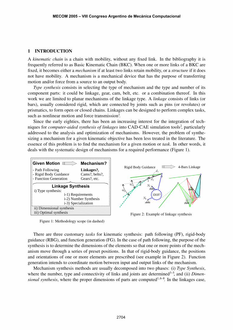
Since the early eighties, there has been an increasing interest for the integration of tech-niques for computer-aided synthesis of linkages into CAD-CAE simulation tools2, particularlyaddressed to the analysis and optimization of mechanisms. However, the problem of synthe-sizing a mechanism for a given kinematic objective has been less treated in the literature. Theessence of this problem is to find the mechanism for a given motion or task. In other words, itdeals with the systematic design of mechanisms for a required performance (Figure 1).
Given Motion
- Path Following- Rigid Body Guidance- Function Generation
Linkages?,Cams?, belts?,Gears?, etc.
Mechanism?
Linkage Synthesisi) Type synthesis:
ii) Dimensional synthesisiii) Optimal synthesis
i-1) Requirementsi-2) Number Synthesisi-3) Specialization
Figure 1: Methodology scope (in dashed)
1DOF?
0
1
21a
2a
d2
N6
N7
d1
Rigid Body Guidance 4-Bars Linkage
Figure 2: Example of linkage synthesis
There are three customary tasks for kinematic synthesis: path following (PF), rigid-bodyguidance (RBG), and function generation (FG). In the case of path following, the purpose of thesynthesis is to determine the dimensions of the elements so that one or more points of the mech-anism move through a series of preset positions. In that of rigid-body guidance, the positionsand orientations of one or more elements are prescribed (see example in Figure 2). Functiongeneration intends to coordinate motion between input and output links of the mechanism.
Mechanism synthesis methods are usually decomposed into two phases: (i) Type Synthesis,where the number, type and connectivity of links and joints are determined3–5, and (ii) Dimen-sional synthesis, where the proper dimensions of parts are computed1, 6–8. In the linkages case,
MECOM 2005 – VIII Congreso Argentino de Mecánica Computacional
2704
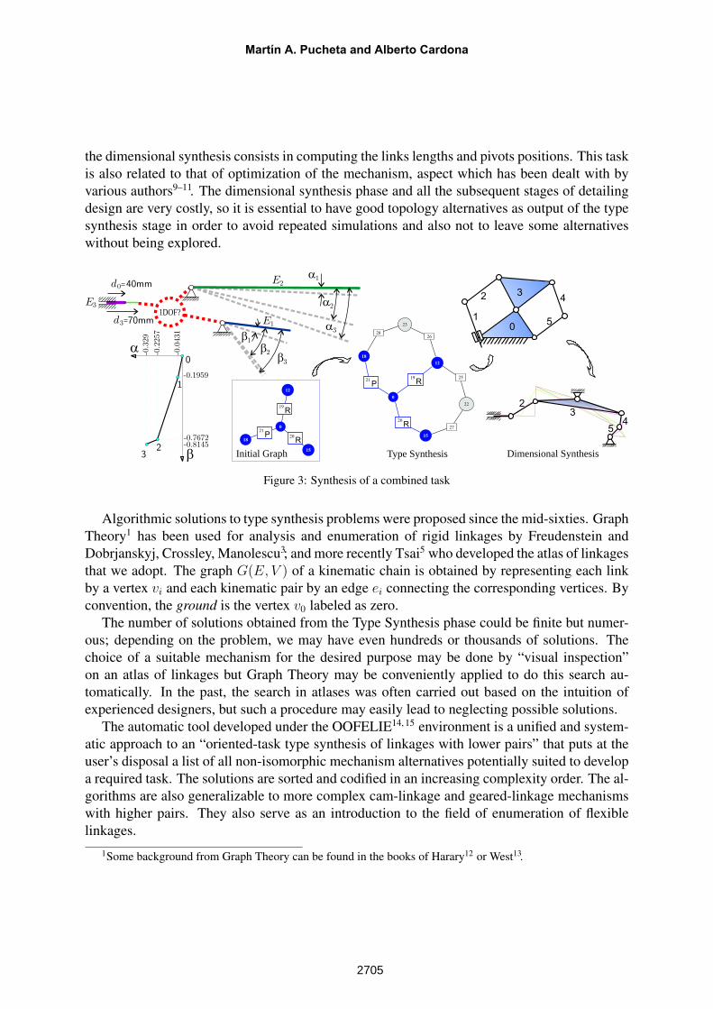
the dimensional synthesis consists in computing the links lengths and pivots positions. This taskis also related to that of optimization of the mechanism, aspect which has been dealt with byvarious authors9–11. The dimensional synthesis phase and all the subsequent stages of detailingdesign are very costly, so it is essential to have good topology alternatives as output of the typesynthesis stage in order to avoid repeated simulations and also not to leave some alternativeswithout being explored.
1a
2a
3a
1b
2b
3b
d3
d0 40mm
70mm
-0.8145
a
b
-0.2
257
-0.3
29
-0.7672
-0.1959
-0.0
431
0
1
23
E3
E2
E1
Initial Graph
0
12
15
1820
R
21
P
19
R
0
12
25
26
15
27
18
28
22
23
19
R21
P
20
R
1DOF?
Type Synthesis
0
1
23
4
5
Dimensional Synthesis
23
45
Figure 3: Synthesis of a combined task
Algorithmic solutions to type synthesis problems were proposed since the mid-sixties. GraphTheory1 has been used for analysis and enumeration of rigid linkages by Freudenstein andDobrjanskyj, Crossley, Manolescu3; and more recently Tsai5 who developed the atlas of linkagesthat we adopt. The graph G(E, V ) of a kinematic chain is obtained by representing each linkby a vertex vi and each kinematic pair by an edge ei connecting the corresponding vertices. Byconvention, the ground is the vertex v0 labeled as zero.
The number of solutions obtained from the Type Synthesis phase could be finite but numer-ous; depending on the problem, we may have even hundreds or thousands of solutions. Thechoice of a suitable mechanism for the desired purpose may be done by “visual inspection”on an atlas of linkages but Graph Theory may be conveniently applied to do this search au-tomatically. In the past, the search in atlases was often carried out based on the intuition ofexperienced designers, but such a procedure may easily lead to neglecting possible solutions.
The automatic tool developed under the OOFELIE14, 15 environment is a unified and system-atic approach to an “oriented-task type synthesis of linkages with lower pairs” that puts at theuser’s disposal a list of all non-isomorphic mechanism alternatives potentially suited to developa required task. The solutions are sorted and codified in an increasing complexity order. The al-gorithms are also generalizable to more complex cam-linkage and geared-linkage mechanismswith higher pairs. They also serve as an introduction to the field of enumeration of flexiblelinkages.
1Some background from Graph Theory can be found in the books of Harary12 or West13.
Martín A. Pucheta and Alberto Cardona
2705
The paper is organized as follows: the process of Type Synthesis is reviewed in Section 2.The graph representation of kinematic problems is shown in Section 3. The enumeration ofkinematic chains is reviewed in Section 4. The proposed Number Synthesis algorithm is de-veloped in Section 5. The proposed algorithms for prismatic joints assignment is developed inSection 6. The topics are developed with detailed examples.
2 TYPE SYNTHESIS PROCESS
Olson3, Erdman and Sandor10, Tsai5, and Yan and Hwang4, gave guidelines for a type synthesisstrategy. The process that we adopt consists in:
I Problem requirements: From the required design specifications, the designer selects thestructural characteristics such as : prescribed parts defined by fixations, bodies to move,joints, and their interconnections, and the kinematic constraints imposed on them. Then,the user sets the required number of degrees of freedom of the mechanism, the allowedjoint types and the maximum number of joints desired for each type. The prescribed partsand kinematic constraints are defined using a CAD interface. From the interpretation ofthis drawing a so called initial graph is automatically constructed to define the problem,as we explain later.
II Number Synthesis: The second step is to enumerate the atlas of the kinematic chainswith the required numbers of links and joints. Methods to obtain an atlas of non-degenerateand non-isomorphic planar kinematic chains with simple joints are available from worksof W. Hwang and Y. Hwang16, Hsieh17, and Tsai5. We use them making a subgraph searchand codifying the occurrences of the initial graph. We dispose the atlas as a list of integerscodifying each BKC by its Degree Code (DC). They are sorted by increasing complexityorder. The identification of an objective link constraints and reduces in cardinality theenumeration of solutions. Depending on the task, it must be at a given distance from theground.
III Specialization: The third step is to specialize each kinematic chain by assigning the typeof links and joints (Yan and Hwang4). The user’s constraints limit the number of permu-tations needed to obtain all possible configurations of mechanisms in a non-isomorphicway. The desired number of joints of each joint type is used as an input constraint. Thetypes of joints pertaining to the initial graph are respected and not changed.
3 GRAPH REPRESENTATION OF KINEMATIC PROBLEMS
Starting from functional requirements, the designer selects the structural characteristics to drawthe existing parts like a skeleton diagram. Many dimensions of this diagram are unknown (to besynthesized), but some of them can be imposed. On the imposed parts the user gives the motionconstraints to define the task. To initiate the Number Synthesis stage, the drawing is convertedinto an abstract structural representation of prescribed parts that we call “initial graph” (Sub-section 3.2). This graph makes it possible to systematically explore potential linkages -usingcombinatorial theory- inside an atlas of kinematic chains.
MECOM 2005 – VIII Congreso Argentino de Mecánica Computacional
2706
3.1 Mechanism class representation
A mechanism is represented internally in a multiple-set of dataM = {N , F , E}, consistingof nodes, fixations and elements with attributes like positions, types of element, connectivities,etc. This representation is entered to the program interactively from a CAD interface which iscommon to other finite element analysis programs. The user may also interact with the programin a special language developed for communication.
0
1
2
d1
d2
0
1
2
R
N4
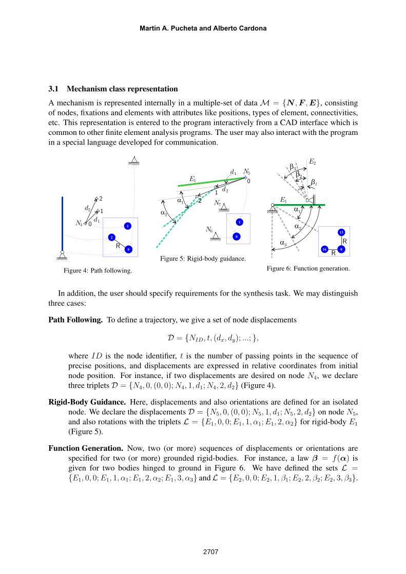
Figure 4: Path following.
0
1
21a
2a
d1
d2
N
0
1
6
N7
N5
E1
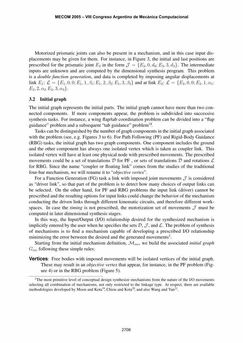
Figure 5: Rigid-body guidance.
1a
2a
3a
1b
2b
3b
0
13
16
R
R
E2
E1
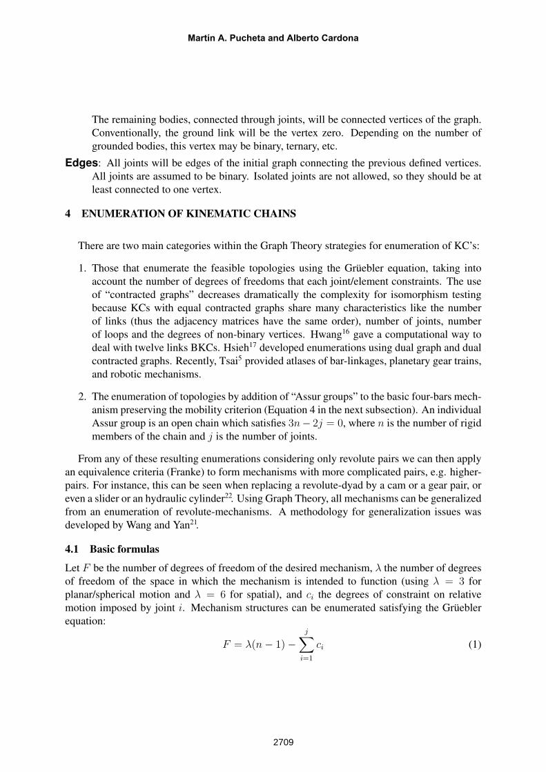
Figure 6: Function generation.
In addition, the user should specify requirements for the synthesis task. We may distinguishthree cases:
Path Following. To define a trajectory, we give a set of node displacements
D = {NID, t, (dx, dy); ...; },
where ID is the node identifier, t is the number of passing points in the sequence ofprecise positions, and displacements are expressed in relative coordinates from initialnode position. For instance, if two displacements are desired on node N4, we declarethree triplets D = {N4, 0, (0, 0); N4, 1, d1; N4, 2, d2} (Figure 4).
Rigid-Body Guidance. Here, displacements and also orientations are defined for an isolatednode. We declare the displacements D = {N5, 0, (0, 0); N5, 1, d1; N5, 2, d2} on node N5,and also rotations with the triplets L = {E1, 0, 0; E1, 1, α1; E1, 2, α2} for rigid-body E1
(Figure 5).
Function Generation. Now, two (or more) sequences of displacements or orientations arespecified for two (or more) grounded rigid-bodies. For instance, a law β = f(α) isgiven for two bodies hinged to ground in Figure 6. We have defined the sets L ={E1, 0, 0; E1, 1, α1; E1, 2, α2; E1, 3, α3} andL = {E2, 0, 0; E2, 1, β1; E2, 2, β2; E2, 3, β3}.
Martín A. Pucheta and Alberto Cardona
2707
Motorized prismatic joints can also be present in a mechanism, and in this case input dis-placements may be given for them. For instance, in Figure 3, the initial and last positions areprescribed for the prismatic joint E3 in the form J = {E3, 0, d0; E3, 3, d3}. The intermediateinputs are unknown and are computed by the dimensional synthesis program. This problemis a double function generation, and data is completed by imposing angular displacements atlink E1: L = {E1, 0, 0; E1, 1, β1; E1, 2, β2; E1, 3, β3} and at link E2: L = {E2, 0, 0; E2, 1, α1;E2, 2, α2 E2, 3, α3}.
3.2 Initial graph
The initial graph represents the initial parts. The initial graph cannot have more than two con-nected components. If more components appear, the problem is subdivided into successivesynthesis tasks. For instance, a wing flap/tab coordination problem can be divided into a “flapguidance” problem and a subsequent “tab guidance” problem18.
Tasks can be distinguished by the number of graph components in the initial graph associatedwith the problem (see, e.g. Figures 3 to 6). For Path Following (PF) and Rigid-Body Guidance(RBG) tasks, the initial graph has two graph components. One component includes the groundand the other component has always one isolated vertex which is taken as coupler link. Thisisolated vertex will have at least one physical node with prescribed movements. The prescribedmovements could be a set of translations D for PF , or sets of translations D and rotations Lfor RBG. Since the name “coupler or floating link” comes from the studies of the traditionalfour-bar mechanism, we will rename it to “objective vertex”.
For a Function Generation (FG) task a link with imposed joint movements J is consideredas “driver link”, so that part of the problem is to detect how many choices of output links canbe selected. On the other hand, for PF and RBG problems the input link (driver) cannot beprescribed and the resulting options for input links could change the behavior of the mechanismconducting the driven links through different kinematic circuits, and therefore different work-spaces. In case the timing is not prescribed, the motorization set of movements J must becomputed in later dimensional synthesis stages.
In this way, the Input/Output (I/O) relationship desired for the synthesized mechanism isimplicitly entered by the user when he specifies the setsD, J , and L. The problem of synthesisof mechanisms is to find a mechanism capable of developing a prescribed I/O relationshipminimizing the error between the desired and the generated movements2.
Starting from the initial mechanism definition, Mini, we build the associated initial graphGini following these simple rules:
Vertices: Free bodies with imposed movements will be isolated vertices of the initial graph.These may result in an objective vertex that appear, for instance, in the PF problem (Fig-ure 4) or in the RBG problem (Figure 5).
2The most primitive level of conceptual design synthesize mechanisms from the nature of the I/O movementsselecting all combination of mechanisms, not only restricted to the linkage type. At respect, there are availablemethodologies developed by Moon and Kota19, Chiou and Kota20, and also Wang and Yan21.
MECOM 2005 – VIII Congreso Argentino de Mecánica Computacional
2708
The remaining bodies, connected through joints, will be connected vertices of the graph.Conventionally, the ground link will be the vertex zero. Depending on the number ofgrounded bodies, this vertex may be binary, ternary, etc.
Edges: All joints will be edges of the initial graph connecting the previous defined vertices.All joints are assumed to be binary. Isolated joints are not allowed, so they should be atleast connected to one vertex.
4 ENUMERATION OF KINEMATIC CHAINS
There are two main categories within the Graph Theory strategies for enumeration of KC’s:
1. Those that enumerate the feasible topologies using the Grüebler equation, taking intoaccount the number of degrees of freedoms that each joint/element constraints. The useof “contracted graphs” decreases dramatically the complexity for isomorphism testingbecause KCs with equal contracted graphs share many characteristics like the numberof links (thus the adjacency matrices have the same order), number of joints, numberof loops and the degrees of non-binary vertices. Hwang16 gave a computational way todeal with twelve links BKCs. Hsieh17 developed enumerations using dual graph and dualcontracted graphs. Recently, Tsai5 provided atlases of bar-linkages, planetary gear trains,and robotic mechanisms.
2. The enumeration of topologies by addition of “Assur groups” to the basic four-bars mech-anism preserving the mobility criterion (Equation 4 in the next subsection). An individualAssur group is an open chain which satisfies 3n− 2j = 0, where n is the number of rigidmembers of the chain and j is the number of joints.
From any of these resulting enumerations considering only revolute pairs we can then applyan equivalence criteria (Franke) to form mechanisms with more complicated pairs, e.g. higher-pairs. For instance, this can be seen when replacing a revolute-dyad by a cam or a gear pair, oreven a slider or an hydraulic cylinder22. Using Graph Theory, all mechanisms can be generalizedfrom an enumeration of revolute-mechanisms. A methodology for generalization issues wasdeveloped by Wang and Yan21.
4.1 Basic formulas
Let F be the number of degrees of freedom of the desired mechanism, λ the number of degreesof freedom of the space in which the mechanism is intended to function (using λ = 3 forplanar/spherical motion and λ = 6 for spatial), and ci the degrees of constraint on relativemotion imposed by joint i. Mechanism structures can be enumerated satisfying the Grüeblerequation:
F = λ(n− 1)−j∑
i=1
ci (1)
Martín A. Pucheta and Alberto Cardona
2709
where n is the number of links, and j the number of joints. The constraints imposed by a jointand the degree of relative motion fi permitted by the joint i are related by:
ci = λ− fi (2)
So, the substitution of (2) into (1) leads to the Grübler or Kutzbach criterion:
F = λ(n− j − 1) +
j∑i=1
fi (3)
Since rotoidal and prismatic joints permit only one d.o.f., the equation for a planar (λ = 3)mechanism with j joints is:
F = 3(n− j − 1) +
j∑i=1
1 = 3(n− j − 1) + j = 3(n− 1)− 2j (4)
The number of independent loops L could be computed from graph theory, as:
L = j − n + 1 (5)
Conversely, combining (5) and (4) yields
F = λ (n− j − 1)︸ ︷︷ ︸−L
+
j∑i=1
fi ⇒j∑
i=1
fi = F + λL (6)
also known as the loop mobility criterion, useful for determining the number of joint degrees offreedom needed for a KC to possess a given number of degrees of freedom.
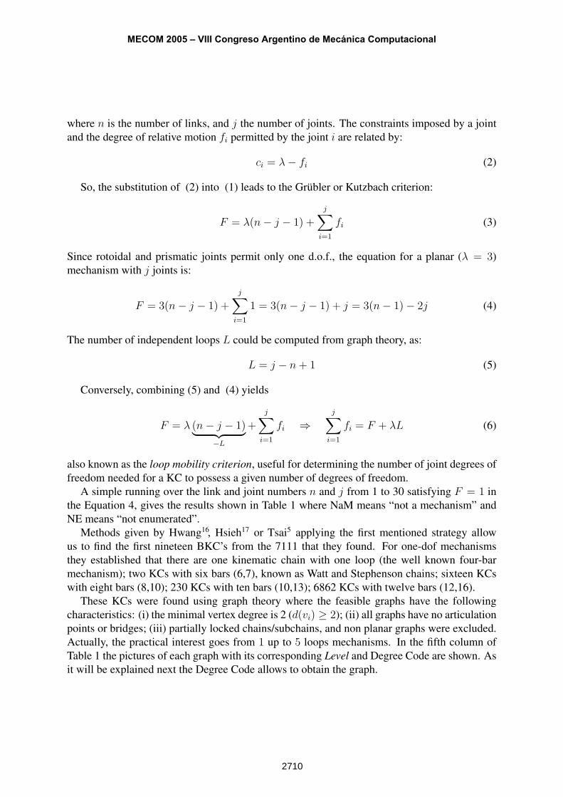
A simple running over the link and joint numbers n and j from 1 to 30 satisfying F = 1 inthe Equation 4, gives the results shown in Table 1 where NaM means “not a mechanism” andNE means “not enumerated”.
Methods given by Hwang16, Hsieh17 or Tsai5 applying the first mentioned strategy allowus to find the first nineteen BKC’s from the 7111 that they found. For one-dof mechanismsthey established that there are one kinematic chain with one loop (the well known four-barmechanism); two KCs with six bars (6,7), known as Watt and Stephenson chains; sixteen KCswith eight bars (8,10); 230 KCs with ten bars (10,13); 6862 KCs with twelve bars (12,16).
These KCs were found using graph theory where the feasible graphs have the followingcharacteristics: (i) the minimal vertex degree is 2 (d(vi) ≥ 2); (ii) all graphs have no articulationpoints or bridges; (iii) partially locked chains/subchains, and non planar graphs were excluded.Actually, the practical interest goes from 1 up to 5 loops mechanisms. In the fifth column ofTable 1 the pictures of each graph with its corresponding Level and Degree Code are shown. Asit will be explained next the Degree Code allows to obtain the graph.
MECOM 2005 – VIII Congreso Argentino de Mecánica Computacional
2710
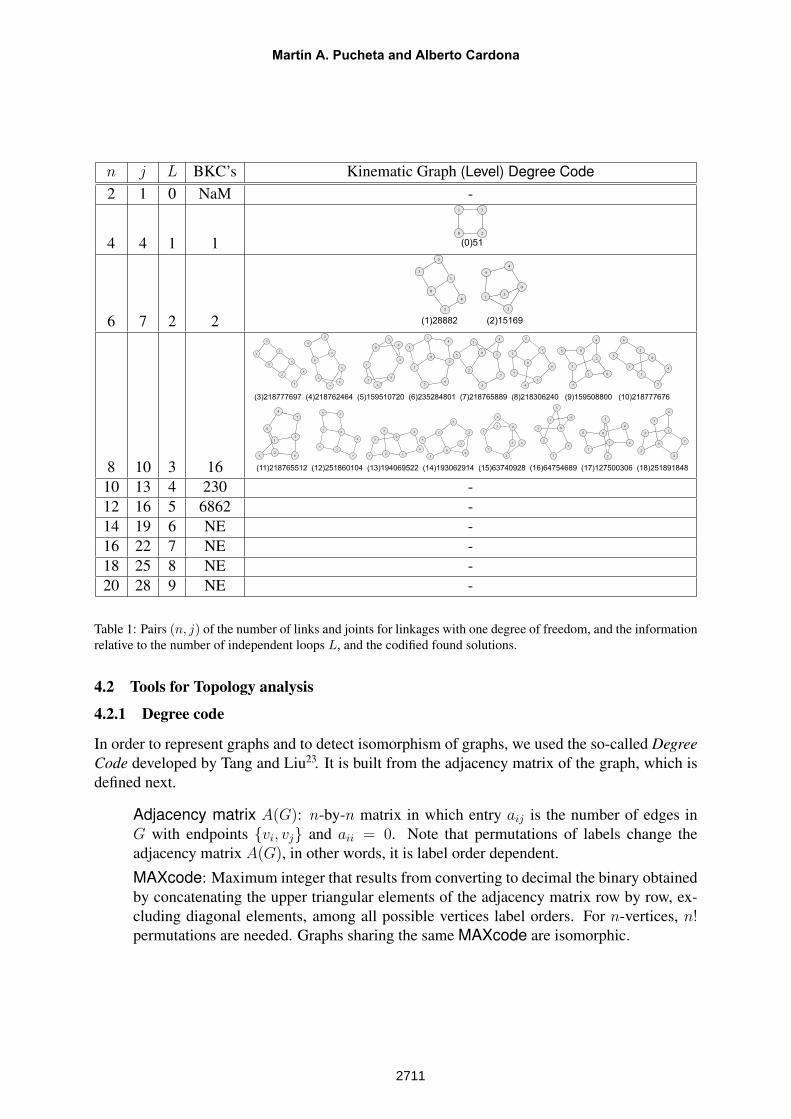
n j L BKC’s Kinematic Graph (Level) Degree Code2 1 0 NaM -
4 4 1 10
1
2
3
(0)51
6 7 2 2
0
2
3
4
1
5
0
1
2
3
4
5
(1)28882 (2)15169
8 10 3 16
0
3
4
5
6
1
2
7
0
2
3
4
5
1 6
7
0
1
2
3
4
5
6
7
01
2
3
4
5
6
7
0
1
3
4
5
6
7
2
0
1
34
5
6
27
03
4
5 6
1
7
2
0
1
2
4
3
5 6
7
0
1
2
4
5
6
7
3
0
1
4
5
6
7
2
3
0
1
2
4
3
5
6
7
0
1
2
4
3
5
6
7
0
1
4
5
6
7
2
3
0
1
2
3
4
5
6
7
0
1
2
4
35
6
7
0
1
2
4
3
5
6
7
(3)218777697 (4)218762464 (5)159510720 (6)235284801 (7)218765889 (8)218306240 (9)159508800 (10)218777676
(11)218765512 (12)251860104 (13)194069522 (14)193062914 (15)63740928 (16)64754689 (17)127500306 (18)251891848
10 13 4 230 -12 16 5 6862 -14 19 6 NE -16 22 7 NE -18 25 8 NE -20 28 9 NE -
Table 1: Pairs (n, j) of the number of links and joints for linkages with one degree of freedom, and the informationrelative to the number of independent loops L, and the codified found solutions.
4.2 Tools for Topology analysis
4.2.1 Degree code
In order to represent graphs and to detect isomorphism of graphs, we used the so-called DegreeCode developed by Tang and Liu23. It is built from the adjacency matrix of the graph, which isdefined next.
Adjacency matrix A(G): n-by-n matrix in which entry aij is the number of edges inG with endpoints {vi, vj} and aii = 0. Note that permutations of labels change theadjacency matrix A(G), in other words, it is label order dependent.
MAXcode: Maximum integer that results from converting to decimal the binary obtainedby concatenating the upper triangular elements of the adjacency matrix row by row, ex-cluding diagonal elements, among all possible vertices label orders. For n-vertices, n!permutations are needed. Graphs sharing the same MAXcode are isomorphic.
Martín A. Pucheta and Alberto Cardona
2711
Degree code (DC): It is computed following the same procedure that the MAXcode,but permutations are taken by subgroups of vertices with the same degree, so that therequired number of permutations is reduced.
The degree code is unique (two graphs with the same DC are isomorphic: DC(G1) =DC(G2) ⇔ G1
∼= G2) and decodable (given the DC, we may build the graph). Then, as it isshown in Table 1, the entire atlas of one degree-of-freedom mechanisms may be very efficientlystored as a sorted list of integers. For instance, a simple four bar kinematic chain labeled as wesee in the first row of Table 1 can be characterized by the integer 51:
A1 =
0 1 1 01 0 0 11 0 0 10 1 1 0
, DC(A1) = ([110][01][1])2 = 1× 20 + 1× 21 + 1× 24 + 1× 25
= 1 + 2 + 16 + 32 = (51)10.
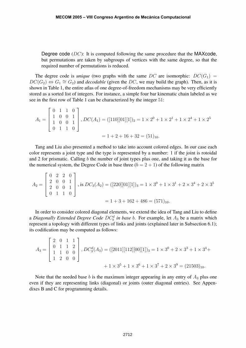
Tang and Liu also presented a method to take into account colored edges. In our case eachcolor represents a joint type and the type is represented by a number: 1 if the joint is rotoidaland 2 for prismatic. Calling b the number of joint types plus one, and taking it as the base forthe numerical system, the Degree Code in base three (b = 2 + 1) of the following matrix
A2 =
0 2 2 02 0 0 12 0 0 10 1 1 0
, is DC3(A2) = ([220][01][1])3 = 1× 30 + 1× 31 + 2× 34 + 2× 35
= 1 + 3 + 162 + 486 = (571)10.
In order to consider colored diagonal elements, we extend the idea of Tang and Liu to definea Diagonally Extended Degree Code DCd
b in base b. For example, let A3 be a matrix whichrepresent a topology with different types of links and joints (explained later in Subsection 6.1);its codification may be computed as follows:
A3 =
2 0 1 10 1 1 21 1 0 01 2 0 0
, DCd3 (A3) = ([2011][112][00][1])3 = 1× 30 + 2× 33 + 1× 34+
+ 1× 35 + 1× 36 + 1× 37 + 2× 39 = (21503)10.
Note that the needed base b is the maximum integer appearing in any entry of A3 plus oneeven if they are representing links (diagonal) or joints (outer diagonal entries). See Appen-dixes B and C for programming details.
MECOM 2005 – VIII Congreso Argentino de Mecánica Computacional
2712
4.2.2 Classes of similar vertices
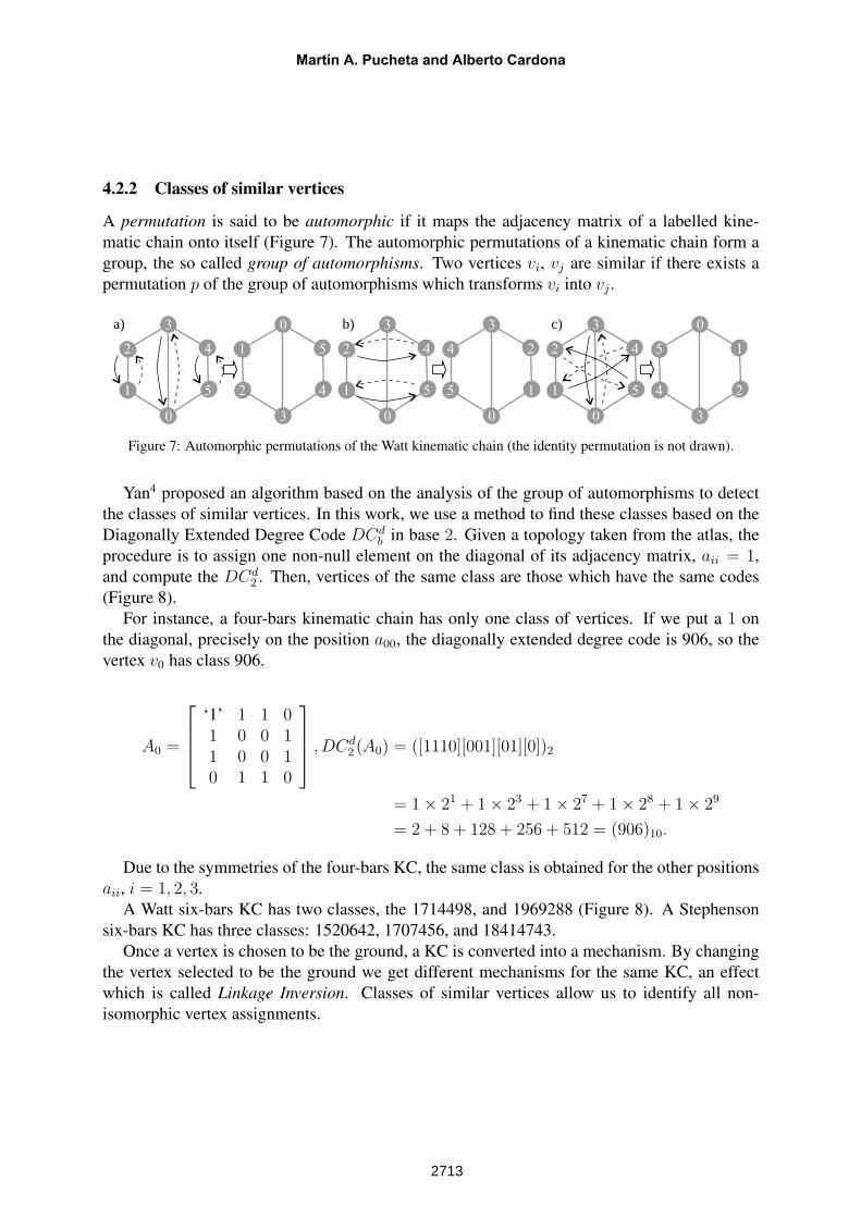
A permutation is said to be automorphic if it maps the adjacency matrix of a labelled kine-matic chain onto itself (Figure 7). The automorphic permutations of a kinematic chain form agroup, the so called group of automorphisms. Two vertices vi, vj are similar if there exists apermutation p of the group of automorphisms which transforms vi into vj .
0
2
1 5
4
3
3
1
2 4
5
0
0
2
1 5
4
3
0
4
5 1
2
3
0
2
1 5
4
3
3
5
4 2
1
0a) b) c)
Figure 7: Automorphic permutations of the Watt kinematic chain (the identity permutation is not drawn).
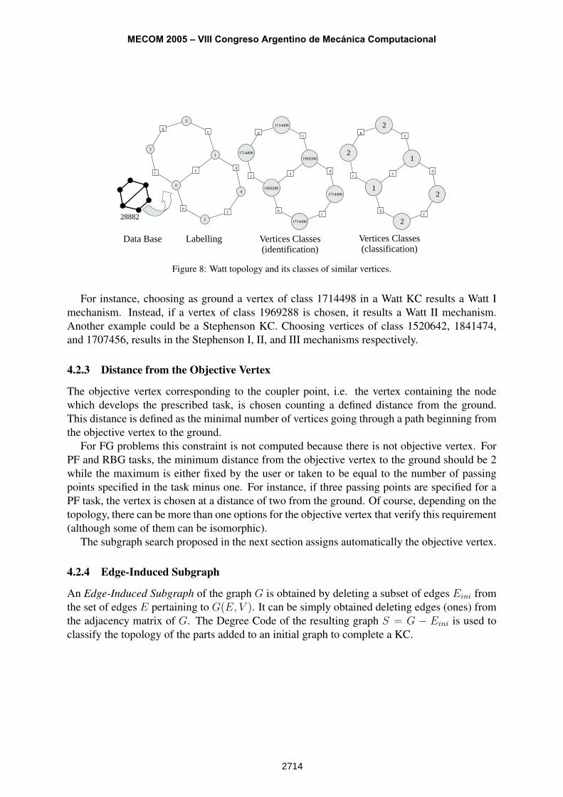
Yan4 proposed an algorithm based on the analysis of the group of automorphisms to detectthe classes of similar vertices. In this work, we use a method to find these classes based on theDiagonally Extended Degree Code DCd
b in base 2. Given a topology taken from the atlas, theprocedure is to assign one non-null element on the diagonal of its adjacency matrix, aii = 1,and compute the DCd
2 . Then, vertices of the same class are those which have the same codes(Figure 8).
For instance, a four-bars kinematic chain has only one class of vertices. If we put a 1 onthe diagonal, precisely on the position a00, the diagonally extended degree code is 906, so thevertex v0 has class 906.
A0 =
‘1’ 1 1 01 0 0 11 0 0 10 1 1 0
, DCd2 (A0) = ([1110][001][01][0])2
= 1× 21 + 1× 23 + 1× 27 + 1× 28 + 1× 29
= 2 + 8 + 128 + 256 + 512 = (906)10.
Due to the symmetries of the four-bars KC, the same class is obtained for the other positionsaii, i = 1, 2, 3.
A Watt six-bars KC has two classes, the 1714498, and 1969288 (Figure 8). A Stephensonsix-bars KC has three classes: 1520642, 1707456, and 18414743.
Once a vertex is chosen to be the ground, a KC is converted into a mechanism. By changingthe vertex selected to be the ground we get different mechanisms for the same KC, an effectwhich is called Linkage Inversion. Classes of similar vertices allow us to identify all non-isomorphic vertex assignments.
Martín A. Pucheta and Alberto Cardona
2713
0
a
b
c
1
d
e
2
f
3
g
4
5
Labelling Vertices Classes(identification)
Vertices Classes(classification)
28882
Data Base
1969288
a
b
c
1969288
d
e
1714498
f
1714498
g
1714498
1714498
1
a
b
c
1
d
e
2f
2
g
2
2
Figure 8: Watt topology and its classes of similar vertices.
For instance, choosing as ground a vertex of class 1714498 in a Watt KC results a Watt Imechanism. Instead, if a vertex of class 1969288 is chosen, it results a Watt II mechanism.Another example could be a Stephenson KC. Choosing vertices of class 1520642, 1841474,and 1707456, results in the Stephenson I, II, and III mechanisms respectively.
4.2.3 Distance from the Objective Vertex
The objective vertex corresponding to the coupler point, i.e. the vertex containing the nodewhich develops the prescribed task, is chosen counting a defined distance from the ground.This distance is defined as the minimal number of vertices going through a path beginning fromthe objective vertex to the ground.
For FG problems this constraint is not computed because there is not objective vertex. ForPF and RBG tasks, the minimum distance from the objective vertex to the ground should be 2while the maximum is either fixed by the user or taken to be equal to the number of passingpoints specified in the task minus one. For instance, if three passing points are specified for aPF task, the vertex is chosen at a distance of two from the ground. Of course, depending on thetopology, there can be more than one options for the objective vertex that verify this requirement(although some of them can be isomorphic).
The subgraph search proposed in the next section assigns automatically the objective vertex.
4.2.4 Edge-Induced Subgraph
An Edge-Induced Subgraph of the graph G is obtained by deleting a subset of edges Eini fromthe set of edges E pertaining to G(E, V ). It can be simply obtained deleting edges (ones) fromthe adjacency matrix of G. The Degree Code of the resulting graph S = G − Eini is used toclassify the topology of the parts added to an initial graph to complete a KC.
MECOM 2005 – VIII Congreso Argentino de Mecánica Computacional
2714
5 SUBGRAPH SEARCHING
The initial graph represents the initial situation. In order to get a mechanism that matches thisinitial situation, the initial graph should be a subgraph of any valid mechanism of the atlas ofmechanisms. Then, the first step of computation consists in looking for the simplest mechanismin the atlas for which the initial graph is a subgraph.
Gini ⊆ GA (7)
with GA a graph from the atlas.The search begins in the lowest level of complexity for the number of degrees of freedom
required for the mechanism. In this way, we try to minimize the number of links in the solution.By default, the number of degrees of freedom is one.
Let L = {l0, l1, ..., lini−1} be the labels of the initial graph Gini, and V the function whichapplies the set L to the set of unlabeled vertices V = {v0, v1, ..., vini−1}, so that V(vi) = li.
The algorithm for selection of a suitable mechanism is the following:
S0. Initialize search level A = −1.
S1. Increase level index A and take a graph GA from the atlas, with nA vertices. If nini ≤ nA,continue to S2; else, repeat S1.
S2. For each permutation GpA of GA, take a subgraph HA of the permuted graph Gp
A. Thevertices of HA are composed by the fist nini vertices of the permuted list of vertices ofGp
A.p(VA) = p({v0, v1, ..., vnA
}) = {vp0, v
p1, ..., v
pini−1︸ ︷︷ ︸
V (HA)
, ..., vpnA}
Label HA using V . There are(
nA
nini
)nini! permutations p to be explored following the
lexicographic order of vertex labels. If all the nini-permutations have been tested in theexplored level, return to S1.
S3. If HA is isomorphic to Gini, HA∼= Gini, then Gini ⊆ Gp
A. Check if connections ofthe graph using the labelled vertices are the same in HA and Gini. If it is true, label theremaining vertices of Gp
A with labels starting from max(li) + 1, i = 0, 1, ..., nini; setGa ← Gp
A and exit. Else, return to S2 and choose a new subgraph HA in lexicographicorder.
At the end, mechanism Ma with graph Ga will be the simplest admissible topology. Theprocess may be repeated resulting in a list of mechanisms with admissible topologies,Ma,Mb,Mc, etc. These mechanisms inherit synthesis data definitions (D, J , L) fromMini, useful tocompute the missing data (i.e. vertices representing new links have unknown node positions) atlater dimensional synthesis stages.
In this way, we performed the number synthesis process, that is, we determined the topology(degrees of freedom, number of links, number of joints and their interconnections) of a suitablemechanism that could answer the requirements.
Martín A. Pucheta and Alberto Cardona
2715
In order to distinguish among topologies Ga, Gb, Gc, etc., we develop a vectorial codification.Each new generated topology is assigned a new vector, which is compared entry-by-entry withthose already stored.
Let us define the edge-induced subgraph S as the graph obtained by deleting from graphGA the subset of edges pertaining to subgraph Gini. Isomorphic occurrences may be detectedby requiring not only that Gini ⊆ Gp
A, but also the DC of S, the distance constraints, and theclasses of its vertices, be different from previous answers. The complete vector for identificationand comparison between the yet stored topologies in S3 consist then of the following four fields:
[A, DC(S), d, C]
where,
A: Integer representing the Level in the atlas (position of the stored Degree Codes of BKCs),
DC(S): Degree code of the edge-induced subgraph S,
d: Distances from the objective vertex vobj to the remaining vertices of the initial graph inGp
A given by d = (d(vobj, v0), d(vobj, v1), d(vobj, v2), ..., d(vobj, vnini−1)). Only the dis-tance from the objective vertex to the ground is constrained by user’s limits dmin ≤d(vobj, v0) ≤ dmax. The remaining are used for classification ends and could take anyvalue.
C: Vector of classes C(vi) of each vertex of the initial graph inside the selected graph GpA
C = (C(v0), C(v1), C(v2), ..., C(vnini−1)).
Their meaning is illustrated next with practical examples.
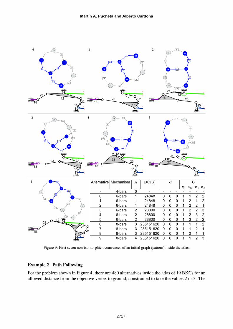
Example 1 Double Function Generation
The problem shown in Figure 3-left schematizes the coordination between two flaps of a turbineengine and the horizontal movement of an hydraulic cylinder. There were 191 solutions foundin the atlas using the present method. The first seven solutions are shown in Figure 9. Forclarity, an schematic sketch is drawn below each solution.
Note that the distance vector d was not computed because there is not objective vertex. Fromsolutions 0, 1, and 2, we see that the vertices labeled with 12 (primary flap), 15 (secondary flap),and 18 (cylinder), have all possible “class vertex” combinations at the different topologies. Onthe other hand, the ground only takes the class 2 (Watt-II) because its degree is prescribed tod(v0) ≥ 3. The same observation is valid for the solutions 3, 4, and 5 where only Stephenson-IIImechanisms are obtained. 2
MECOM 2005 – VIII Congreso Argentino de Mecánica Computacional
2716
0 1 2
3 4 5
6
18
23
12
22
15
v0 v12 v15 v18
Alternative Mechanism A DC(S)
- 4-bars 0 - - - - - - - -
0 6-bars 1 24848 0 0 0 1 1 2 2
1 6-bars 1 24848 0 0 0 1 2 1 2
2 6-bars 1 24848 0 0 0 1 2 2 1
3 6-bars 2 28800 0 0 0 1 2 2 3
4 6-bars 2 28800 0 0 0 1 2 3 2
5 6-bars 2 28800 0 0 0 1 3 2 2
6 8-bars 3 235151620 0 0 0 1 1 1 2
7 8-bars 3 235151620 0 0 0 1 1 2 1
8 8-bars 3 235151620 0 0 0 1 2 1 1
9 8-bars 4 235151620 0 0 0 1 1 2 3
d C
1823
1222
15
1823
12
22
15
18
23 12
22
15
18
23
12
22
15
18
2312
22
15
18
2312
22
15
25
24
0
19
20
21
12
25
26
27
18
28
22
23
15
19
20
2125
26
27
28
22
23
0
12
15
18
19
20
21
25
26
27
28
22
23
0
12
15
18
19
20
21
12
25
26
27
22
2823
0 15
18
19
20
21
25
26
27
22
28
23
012
15
18
19
20
21
25
26
27
22
28
23
0
12
15
18
19
20
21
27
28
29
30
31
22
32
23
33
25
24
0
12
15
18
Figure 9: First seven non-isomorphic occurrences of an initial graph (pattern) inside the atlas.
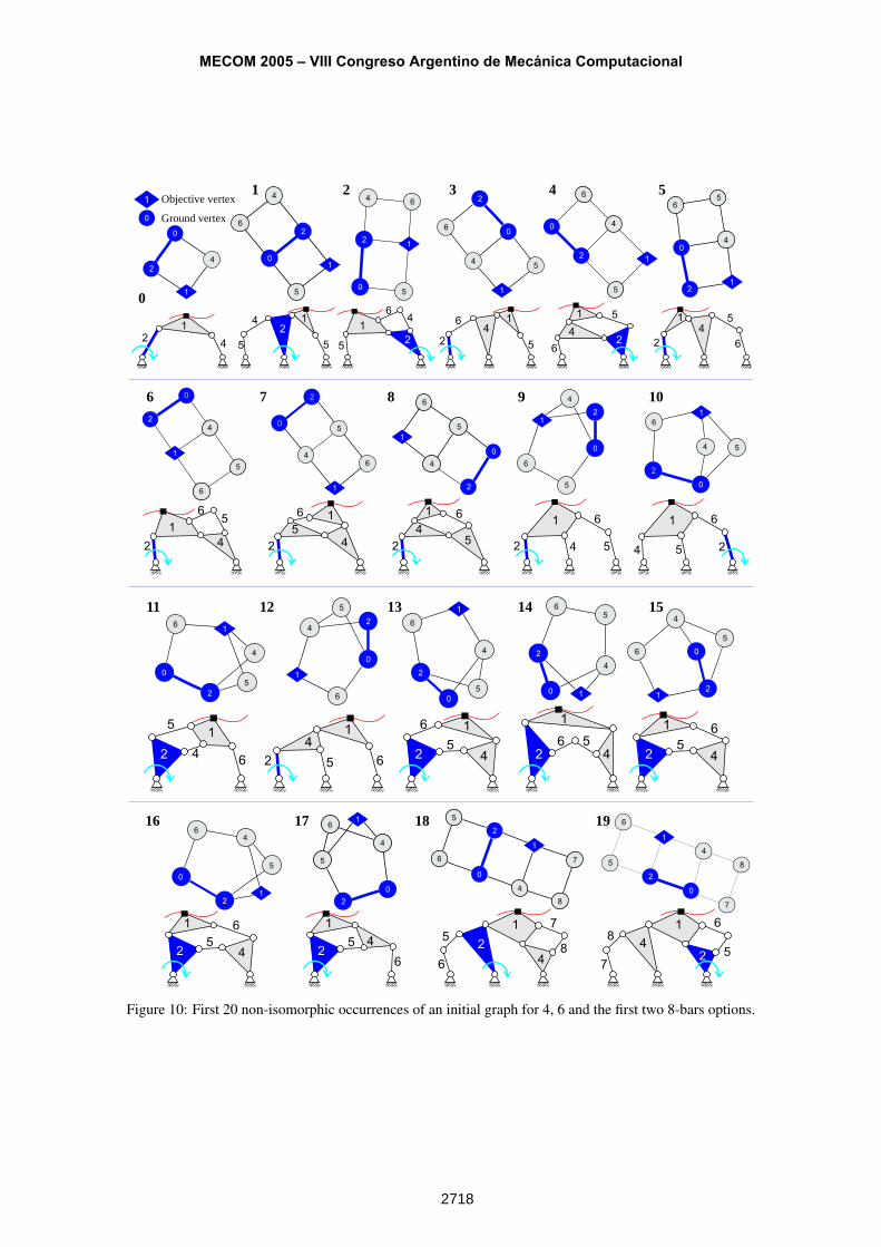
Example 2 Path Following
For the problem shown in Figure 4, there are 480 alternatives inside the atlas of 19 BKCs for anallowed distance from the objective vertex to ground, constrained to take the values 2 or 3. The
Martín A. Pucheta and Alberto Cardona
2717
6
0
2
4
5
1 4
0
0
2
5
1
6
1
5
6
4
1
2
0
1
0
2
4
5
1
6
1
2
4 5
6
0
1
1
0
2
4
5
6
1
0
2
5
4
60
2
4
6
5
1
0
2
6
4
5
1
0
2
4
5
6
1
1 Objective vertex
0 Ground vertex
2
4
0
1
4
1
0
2
5
6
1
0
6
4
5
121
0
4
6
5
21
0
2
5
4
1
6
1
4
2
0
5
6
1
2
0
2
4
5
1
61
0
2
4
7
5
6
8
1
0
2
6
5
4
1
0
1
6
2
5
7
1
8
4
0
1 2 3 4 5
6 7 8 9 10
16 17 18 19
42
14 1
2
5 5
4
16
52
4
1
6
5
2
41
6
52
4
1 5
62
42
51
6
42
5
16
52
4
1 6
4
1 6
52 4
1 6
5 2
4
1
52 64
15
26 4
1
52
6
4
1
5
2
6
4
1
52
6
4
1
52
6
4
1
52
6
1
2
6
5
4
7
8
1
2
6
54
7
8
11 12 13 14 15
Figure 10: First 20 non-isomorphic occurrences of an initial graph for 4, 6 and the first two 8-bars options.
MECOM 2005 – VIII Congreso Argentino de Mecánica Computacional
2718
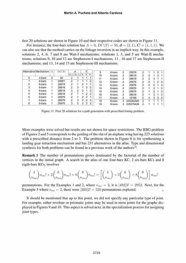
first 20 solutions are shown in Figure 10 and their respective codes are shown in Figure 11.For instance, the four-bars solution has A = 0, DC(S) = 50, d = (2, 1), C = (1, 1, 1). We
can also see that the method carries on the linkage inversion in an implicit way. In this example,solutions 2, 4, 6, 7 and 8 are Watt-I mechanisms; solutions 1, 3, and 5 are Watt-II mecha-nisms; solutions 9, 10 and 12 are Stephenson-I mechanisms; 11 , 16 and 17 are Stephenson-IImechanisms; and 13, 14 and 15 are Stephenson-III mechanisms.
v0 v1 v2d( 1 0v ,v )d( 1 2v ,v )
Alternative Mechanism A DC(S)
0 4-bars 0 50 2 1 1 1 1
1 6-bars 1 24851 2 1 1 1 2
2 6-bars 1 28818 2 1 2 1 1
3 6-bars 1 28818 2 3 1 2 2
4 6-bars 1 28818 3 2 2 1 2
5 6-bars 1 28818 2 1 1 2 2
6 6-bars 1 26976 2 1 2 2 1
7 6-bars 1 26976 2 3 2 2 2
8 6-bars 1 26976 3 2 2 2 2
d C 9 6-bars 2 25876 2 1 1 2 1
10 6-bars 2 28818 2 2 1 3 1
11 6-bars 2 28818 2 2 3 1 1
12 6-bars 2 25876 2 2 1 2 3
13 6-bars 2 25876 2 2 2 1 3
14 6-bars 2 25876 2 1 2 1 2
15 6-bars 2 25876 2 1 2 1 3
16 6-bars 2 28818 2 1 3 1 2
17 6-bars 2 15168 2 2 3 3 2
18 8-bars 3 235282563 2 1 1 1 1
19 8-bars 3 235276426 2 1 1 1 1
Figure 11: First 20 solutions for a path generation with prescribed timing problem.
More examples were solved but results are not shown for space restrictions. The RBG problemof Figures 2 and 5 corresponds to the guiding of the slat of an airplane wing having 223 solutionswith a prescribed distance from 2 to 3. The problem shown in Figure 6 is for synthesizing alanding gear retraction mechanism and has 231 alternatives in the atlas. Type and dimensionalsynthesis for both problems can be found in a previous work of the authors24.
Remark 1 The number of permutations grows dominated by the factorial of the number ofvertices in the initial graph. A search in the atlas of one four-bars KC, 2 six-bars KCs and 8eigth-bars KCs, involves(
4
nini
)nini! + 2
(6
nini
)nini! + 8
(8
nini
)nini! =
[(4
nini
)+ 2
(6
nini
)+ 8
(8
nini
)]nini!
permutations. For the Examples 1 and 2, where nini = 3, it is [492]3! = 2952. Next, for theExample 3 where nini = 2, there were [260]2! = 520 permutations explored. 2
It should be mentioned that up to this point, we did not specify any particular type of joint.For example, either revolute or prismatic joints may be used in most joints for the graphs dis-played in Figures 9 and 10. This aspect is solved next, in the specialization process for assigningjoint types.
Martín A. Pucheta and Alberto Cardona
2719
6 JOINT ASSIGNMENT: SPECIALIZATION
Three previous works gave foundations to the computer enumeration and assignment of linkand joint types in the type synthesis of mechanisms:
• Algorithm based on permutation groups:Yan and Hwang4 developed a method based on combinatorial theory for enumeratingnon-isomorphic specialized mechanisms precisely, starting from a specified kinematicchain. They developed an algorithm for finding the “permutation groups of a kinematicchain” (the link permutation group in conjunction with the joint permutation group) fromits labeled link adjacency matrix. Based on these permutation groups they generated allnon-isomorphic specialized mechanisms by assigning various types to the links and jointsof the kinematic chain.
• Algorithm based on the Characteristic Polynomial:Murphy, Midha and Howell25 developed a method for compliant mechanisms limited tobinary pairs using the pseudo-rigid-body concept and defining the Compliant Segmentand Compliant Connection vectors for enumeration. They also defined a Compliant Ma-trix (CM) where the diagonal entries represent the links/segments and outer diagonalentries represent the type of joints/edges. The polynomial expression used to find theeigenvalues of each CM, called characteristic polynomial CP (CM) = |xI − CM |, isused to detect isomorphic mechanisms based on the theorem that states “The adjacencymatrices of two isomorphic kinematic chains possess the same characteristic polynomial(CP)”3.
• Algorithm based in combinatorial analysis: This approach was proposed by Freuden-stein and Maki28, and then extensively used by Tsai for joint assignment of kinematicchains, parallel platforms, geared automotive transmissions, robotic wrist mechanisms.
Our proposal is a combination of them, adding the “initial graph concept” to take accountof the user defined constraints and also limit the combinatorial explosion. For instance, onceGini is found as subgraph of Gp
a, we do not assign new types to joints that are connectingvertices inside of the isomorphic graph of Gini in Gp
a, respecting the joint types defined by theuser as prescribed parts. For this purpose, we first classify the joints in two groups: (i) thoseprescribed by the user, which are of fixed joints group, and (ii) those given by specializationusing combinatorial analysis, which are added from a set of allowable types given by the userand positioned in the graph using some heuristic rules to be explained.
For adding prismatic joints, we can take into account singularities that can appear due to pris-matic joint behavior and the number and orientation of prismatic joints over a link/circuit. Some
3Yan and Hall26, 27 have deeply studied the use of the CP for mechanisms. By counter examples Yan and alsoTsai found that this theorem is a necessary but not sufficient condition for two KCs be isomorphic, so that theconversely is not true and two non-isomorphic KCs could share the same CP. Nevertheless, the CP is still in usefor isomorphism testing purposes for KCs with less than 10 links.
MECOM 2005 – VIII Congreso Argentino de Mecánica Computacional
2720
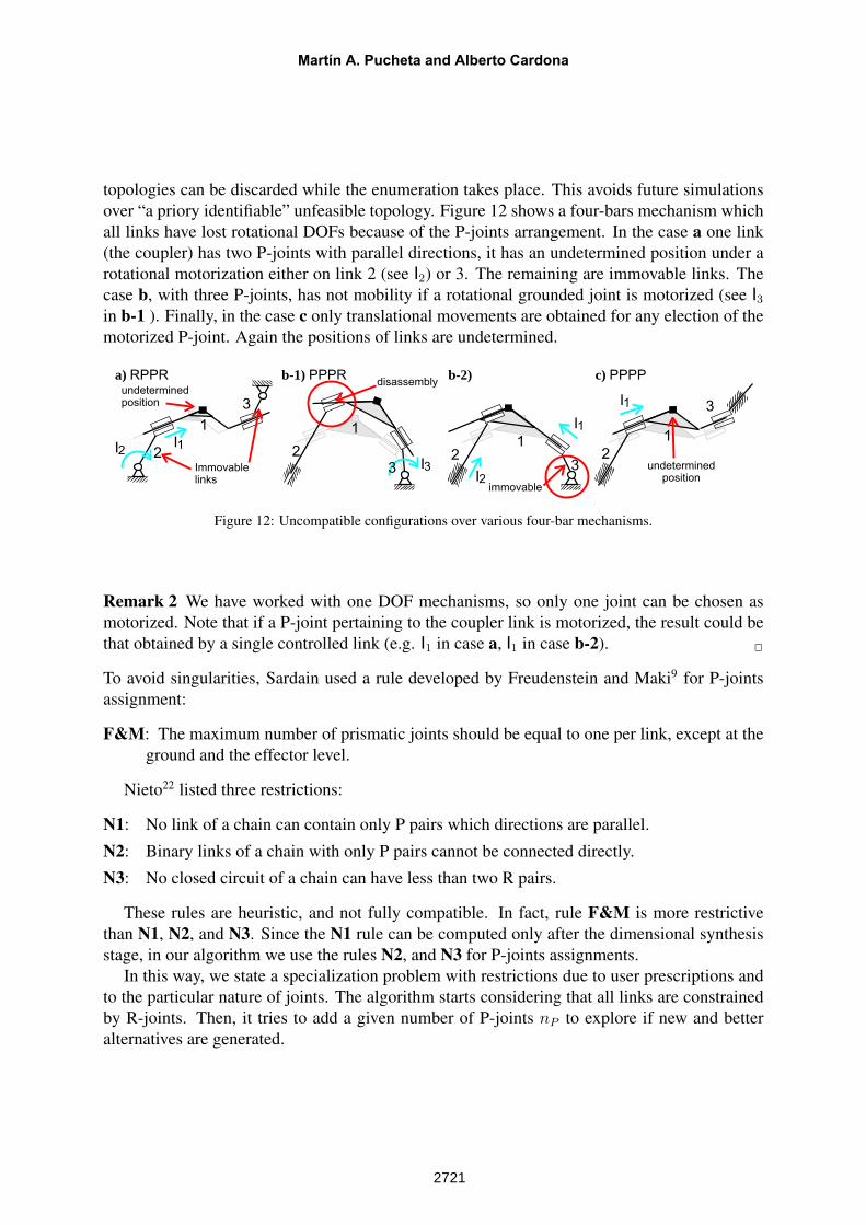
topologies can be discarded while the enumeration takes place. This avoids future simulationsover “a priory identifiable” unfeasible topology. Figure 12 shows a four-bars mechanism whichall links have lost rotational DOFs because of the P-joints arrangement. In the case a one link(the coupler) has two P-joints with parallel directions, it has an undetermined position under arotational motorization either on link 2 (see I2) or 3. The remaining are immovable links. Thecase b, with three P-joints, has not mobility if a rotational grounded joint is motorized (see I3in b-1 ). Finally, in the case c only translational movements are obtained for any election of themotorized P-joint. Again the positions of links are undetermined.
3
2
1
I1
undetermined
position
I2
Immovable
links
a) RPPRdisassembly
b-1) PPPR
3
2
1
I3
b-2)
I23
2
1
immovable
I1
3
2
1
undetermined
position
c) PPPP
I1
Figure 12: Uncompatible configurations over various four-bar mechanisms.
Remark 2 We have worked with one DOF mechanisms, so only one joint can be chosen asmotorized. Note that if a P-joint pertaining to the coupler link is motorized, the result could bethat obtained by a single controlled link (e.g. I1 in case a, I1 in case b-2). 2
To avoid singularities, Sardain used a rule developed by Freudenstein and Maki9 for P-jointsassignment:
F&M: The maximum number of prismatic joints should be equal to one per link, except at theground and the effector level.
Nieto22 listed three restrictions:
N1: No link of a chain can contain only P pairs which directions are parallel.
N2: Binary links of a chain with only P pairs cannot be connected directly.
N3: No closed circuit of a chain can have less than two R pairs.
These rules are heuristic, and not fully compatible. In fact, rule F&M is more restrictivethan N1, N2, and N3. Since the N1 rule can be computed only after the dimensional synthesisstage, in our algorithm we use the rules N2, and N3 for P-joints assignments.
In this way, we state a specialization problem with restrictions due to user prescriptions andto the particular nature of joints. The algorithm starts considering that all links are constrainedby R-joints. Then, it tries to add a given number of P-joints nP to explore if new and betteralternatives are generated.
Martín A. Pucheta and Alberto Cardona
2721
6.1 Synthesized joints: added joints group
For a given topology, when we make the specialization of the added joints group, there appearsagain the problem of isomorphism detection but now due to joint types. A systematic strategyfor identification, enumeration and retrieval of alternatives is needed.
We define a colored adjacency matrix with the complete information of the topology. Fol-lowing Murphy25, we put link characteristics on the diagonal entries and the joint characteristicson the outer diagonal ones, but consider the entries in a different way.
The colored adjacency matrix is filled as follows: Aii = 1 if the vertex i pertain to the initialgraph (including the ground), Aii = 2 if the vertex i is the objective vertex and, Aii = 0 if i isa type synthesized vertex. The joint types are represented by the symmetric entries, Aij = 1for rotoidal joint type, Aij = 2 for prismatic joint type, and Aij = 0 if no connection appears.Summarizing, we define:
Aii =
1 if vi ∈ Gini,
2 if vi = vobj,
0 otherwise,Aij =
1 Rotoidal joint,2 Prismatic joint,0 no connection.
Let Ea be the set of the added joints group Ea = E(GpA)− E(Gini), and be na the number
of synthesized joints (na = |E(GpA)| − |E(Gini)|).
To limit the search, the user can define a prescribed number of P-joints nP to add in Ea.The number of combinations for adding exactly nP P-joints is
(na
nP
). For classification, all nP -
combinations of P-joints in the set Ea are assigned. For a given combination i, the degree codein base 3 DCd
3 (Ai) is computed. The solution is retained only if the degree code is differentfrom all those already stored.
Once the enumeration is finished, the code of the colored topology DCd3 can also be used for
retrieving a solution. See Appendix B.
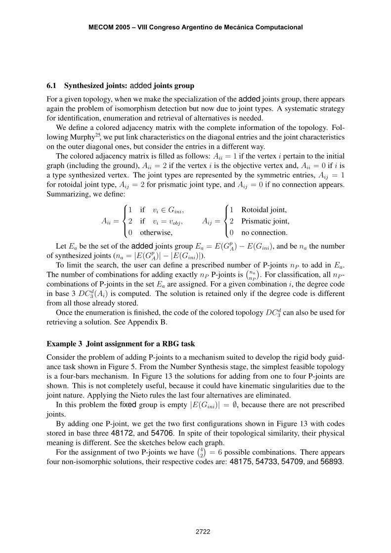
Example 3 Joint assignment for a RBG task
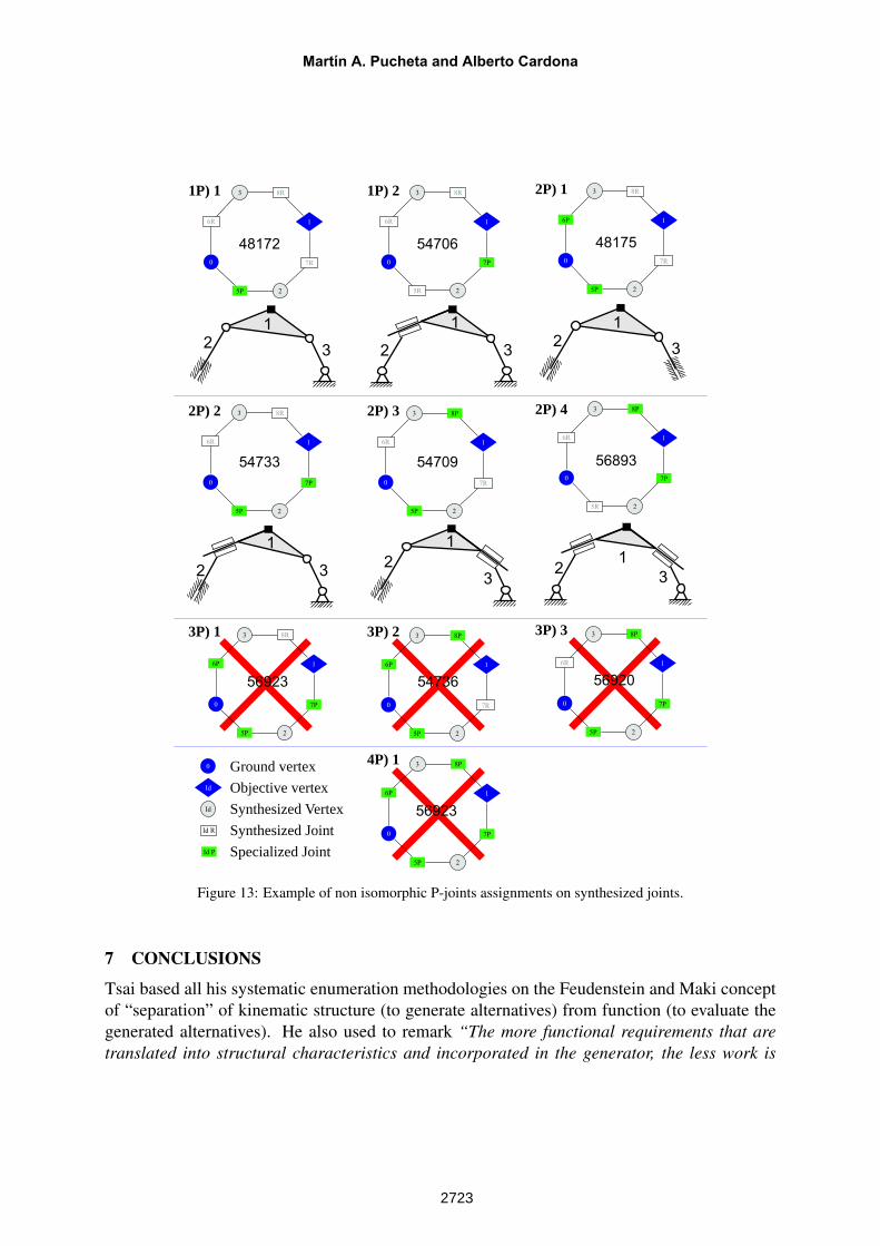
Consider the problem of adding P-joints to a mechanism suited to develop the rigid body guid-ance task shown in Figure 5. From the Number Synthesis stage, the simplest feasible topologyis a four-bars mechanism. In Figure 13 the solutions for adding from one to four P-joints areshown. This is not completely useful, because it could have kinematic singularities due to thejoint nature. Applying the Nieto rules the last four alternatives are eliminated.
In this problem the fixed group is empty |E(Gini)| = ∅, because there are not prescribedjoints.
By adding one P-joint, we get the two first configurations shown in Figure 13 with codesstored in base three 48172, and 54706. In spite of their topological similarity, their physicalmeaning is different. See the sketches below each graph.
For the assignment of two P-joints we have(42
)= 6 possible combinations. There appears
four non-isomorphic solutions, their respective codes are: 48175, 54733, 54709, and 56893.
MECOM 2005 – VIII Congreso Argentino de Mecánica Computacional
2722
0
5P
6R 1
7R
8R
2
3
0
5R
6R 1
7P
8R
2
3
0
5P
6P 1
7R
8R
2
3
0
5P
6R 1
7P
8R
2
3
0
5P
6R 1
7R
8P
2
3
0
5R
6R 1
7P
8P
2
3
0
5P
6P 1
7P
8R
2
3
0
5P
7R
16P
8P
2
3
0
5P
6P 1
7P
8P
2
30
Id
Id P
Id
Ground vertex
Objective vertex
Synthesized Vertex
Specialized Joint
Id R Synthesized Joint
48172 54706
56923 54736
56923
32
1
32
1
32
1
3232
1
12
1
3
48175
54733 54709 56893
0
5P
6R 1
7P
8P
2
3
56920
1P) 1 1P) 2 2P) 1
2P) 2 2P) 3 2P) 4
3P) 1 3P) 2 3P) 3
4P) 1
Figure 13: Example of non isomorphic P-joints assignments on synthesized joints.
7 CONCLUSIONS
Tsai based all his systematic enumeration methodologies on the Feudenstein and Maki conceptof “separation” of kinematic structure (to generate alternatives) from function (to evaluate thegenerated alternatives). He also used to remark “The more functional requirements that aretranslated into structural characteristics and incorporated in the generator, the less work is
Martín A. Pucheta and Alberto Cardona
2723
needed from the evaluator. However, this may make the generator too complex to develop.Generally, if a functional requirement can be written in a mathematical form, it should beincluded in the generator”.
In this work we have experienced his words since we have “integrated” more structural char-acteristics using the initial graph concept, developing a more complex generator. This dimin-ishes considerably the time computation in all subsequent stages of design. For the next di-mensional synthesis stage the information of the known nodes and the type-synthesized graphstructure could be used to apply either a general absolute/natural coordinate formulation orthe complex number formulation based on the decomposition of the topology into open chains(Sandor1, Cardona18, Pucheta and Cardona24).
The main contribution of this work is to offer a systematic procedure to obtain topologi-cal alternatives for a given kinematic problem. New algorithms based on Graph theory andcombinatorial analysis were developed to search and codify the solutions in a non isomorphicway.
Other remarkable characteristics are:
• The use of an enumerated atlas assures that all candidate mechanisms satisfy the requireddegree of freedom and does not contain rigid subchains.
• The number of solutions is finite and the combinatorial explosion is manageable.
• The designed Diagonally Extended Degree Code allows coding and decoding of solutionsin an efficient and straightforward way.
Murphy et al.25 and also Howell25, 29 prove that rigid-body enumeration is an essential start-ing for type synthesis of compliant mechanisms.
The algorithms are useful for dealing with more types of links and joints in the mechanismand even more complex tasks. However, like we seen for prismatic joints, adequate rules toreject those kinematically invalid solutions must be properly designed.
8 ACKNOWLEDGMENTS
This work has received financial support from Consejo Nacional de Investigaciones Científicasy Técnicas, Agencia Nacional de Promoción Científica y Tecnológica, Universidad Nacional delLitoral (CONICET, ANPCyT and UNL, from Argentina) and from the European Communitythrough grant SYNCOMECS (SYNthesis of COmpliant MEChanical Systems) project UE FP6-2003-AERO-1-516183.
REFERENCES
[1] G.N. Sandor and A.G. Erdman. Advanced Mechanism Design: Analysis and Synthesis,volume 2. Prentice-Hall, New Jersey, (1984).
[2] A.G. Erdman. Computer-aided design of mechanisms: 1984 and beyond. Mechanism andMachine Theory, 20, 245–249 (1985).
MECOM 2005 – VIII Congreso Argentino de Mecánica Computacional
2724
[3] D.G. Olson, A.G. Erdman, and D.R. Riley. A systematic procedure for type synthesis ofmechanisms with literature review. Mechanism and Machine Theory, 20, 285–295 (1985).
[4] H.S. Yan and Y.W. Hwang. The specialization of mechanisms. Mechanism and MachineTheory, 26, 541–551 (1991).
[5] Lung-Wen Tsai. Mechanism Design: Enumeration of Kinematic Structures According toFunction. CRC Press, Boca Raton, (2001).
[6] A. S. Hall Jr. Kinematics and Linkage Design. Waveland Press, U.S.A., (1961).[7] C.S. Lin, A.G. Erdman, and B.P. Jia. Use of compatibility linkages and solution structures
in the dimensional synthesis of mechanism components. Mechanism and Machine Theory,31, 619–635 (1996).
[8] J.M. McCarthy. Geometric Design of Linkages. Springer, (2000).[9] P. Sardain. Linkage synthesis: Topology selection fixed by dimensional constraints, study
of an example. Mechanism and Machine Theory, 32, 91–102 (1997).[10] A.G. Erdman and G.N. Sandor. Mechanism Design: Analysis and Synthesis, volume 1.
Prentice-Hall, New Jersey, 3rd edition, (1997).[11] M.R. Hansen. A multi level approach to synthesis of planar mechanisms. In Computer
Aided Analysis of Rigid and Flexible Mechanical Systems, (1993).[12] F. Harary. Graph Theory. Addison-Wesley Series in mathematics, (1969).[13] D.B. West. Introduction to Graph Theory. Prentice Hall, (2001).[14] A. Cardona, I. Klapka, and M. Géradin. Design of a new finite element programming
environment. Engineering Computations, 11 (1994).[15] Open Engineering S.A. OOFELIE: Oriented Object Finite Elements Led by Interactive
Executor. http://www.open-engineering.com.[16] W-M Hwang and Y-W Hwang. Computer-aided structural synthesis of planar kinematic
chains with simple joints. Mechanism and Machine Theory, 27, 189–199 (1992).[17] H-I Hsieh. Sistematic methodologies for the automatic enumeration of topological struc-
tures of mechanisms. Master’s thesis, University of Maryland, USA, (1992).[18] A. Cardona. Computational Methods for Synthesis of Mechanisms. Technical report,
CIMEC-INTEC, (2002).[19] Y-M Moon and S. Kota. Automated synthesis of mechanisms using dual vector algebra.
Mechanism and Machine Theory, 37, 143–166 (2002).[20] S.J. Chiou and S. Kota. Automated conceptual design of mechanisms. Mechanism and
Machine Theory, 34, 467–495 (2004).[21] Y-X Wang and H-S Yan. Computerized rules-based regeneration method for conceptual
design of mechanisms. Mechanism and Machine Theory, 37, 833–849 (2002).[22] J. Nieto Nieto. Síntesis de Mecanismos. Editorial AC, Madrid, (1977).[23] C.S. Tang and T. Liu. The degree code - a new mechanism identifier. ASME Journal of
Mechanical Design, 115, 627–630 (1993).[24] M.A. Pucheta and A. Cardona. Type synthesis and initial sizing of planar linkages using
graph theory and classic genetic algorithms starting from parts prescribed by user. InMultibody Dynamics 2005, ECCOMAS Thematic Conference, (2005).
Martín A. Pucheta and Alberto Cardona
2725

[25] M.D. Murphy, A. Midha, and L.L. Howell. The topological synthesis of compliant mech-anisms. Mechanism and Machine Theory, 31, 185–199 (1996).
[26] H.S. Yan and A.S. Hall. Linkage characteristic polynomials: Definition, coefficients byinspection. ASME Journal of Mechanical Design, 103, 578–584 (1981).
[27] H.S. Yan and A.S. Hall. Linkage characteristic polynomials: Assembly theorem, unique-ness. ASME Journal of Mechanical Design, 104, 11–20 (1982).
[28] F. Freudenstein and E.R. Maki. Creation of mechanisms according to kinematic structureand function. Journal of Environmental and Planning B, 6, 375–391 (1979).
[29] L.L. Howell. Compliant Mechanisms. John Wiley & Sons, New York, (2001).
A PERMUTATIONS
A permutation of n distinct elements x1, . . . , xn is an ordering of the n elements x1, . . . , xn.By the Multiplication Principle, there are
n(n− 1)(n− 2) · · · 2 · 1 = n!
permutations of n elements.A r-permutation of n (distinct) elements x1, . . . , xn is an ordering of an r-element subset of
{x1, . . . , xn}. The number of r-permutations of a set of n distinct elements is denoted P (n, r),where
P (n, r) = n(n− 1)(n− 2) · · · (n− r − 1) =n!
(n− r)!, r ≤ n.
A selection of n distinct elements x1, . . . , xn without regard to order is called a combination.A r-combination of a given set X = {x1, . . . , xn} is an unordered selection of r-elements of X .The number of r-combinations of a set of n distinct elements is denoted C(n, r) or
(nr
), where
C(n, r) =P (n, r)
r!=
n!
(n− r)!r!, r ≤ n.
In permutations and combinations used in this work repeated elements are not allowed. Forinstance, we generate all r-permutations of an n-element set to explore subgraphs inside agraph. Sets with unordered and repeated elements concern to Generalized Permutations andCombinations Theory and will be used in future for more than one type of links and joints.
B RETRIEVING MECHANISMS FROM INTEGER CODES
Given a DCdb , and the base b of a KC we can retrieving the a stored mechanism. For instance,
for R and P joints we need a base three, so b = 3.Let DCd
3 a degree code stored in base 3, for the n×n adjacency matrix A of a graph G(E, V )with n vertices and e edges.
The matrix A has a number of m significative entries (including the diagonal). To find it we
MECOM 2005 – VIII Congreso Argentino de Mecánica Computacional
2726
made
3m = DCd3 ; log10(3
m) = log10(DCd3 ); m =
⌈log10(DCd
3 )
log10(3)
⌉In general,
m =
⌈log10(DCd
b )
log10(b)
⌉To find the size n of A, we know that
n× n− n
2+ n = m;
n2 + n
2= m
this leads to solving the quadratic expression
n2 + n− 2m = 0
so, n is
n1,2 = −1
2± 1
2
√8m + 1
and rounded the higher solution to the nearest integer we have
n =
⌈−1
2+
√8m + 1
2
⌉.
Knowing DCdb (code) and b (nb_colors) we can also identify the number of edges en the
types of each edge using an algorithm for computing the digits in b-base of the DCb in 10-base.To give an idea, the algorithm in C++ code is
int d,u,i,j,coef,e=0;float base = (float)nb_colors+1;int m = ceil(log10((float)code)/log10(base));int n = ceil((-1.0+sqrt(8.0*m+1))/2.0);Graph A(n); // adjacency matrixd = n; // diagonal indexu = m-n; // upper diagonal indexstd::vector <int> links (d);std::vector <int> joints (u);e=0;for (i=n-1;i>=0;i--)
for (j=n-1;j>=i;j--) {coef =fmod(code,base);if (i==j) links[--d] = coef;else{
joints[--u] = coef;
Martín A. Pucheta and Alberto Cardona
2727

if (coef){A.Connect(i,j);e++;
}}code -= coef;code /= base;
};
where Graph is a class of graphs and the member function Connect sets simultaneouslya 1 in the (i,j) and (j,i) entries. The number of vertices/links is n, the number ofedges/joints is e. We get the adjacency matrix in A, the links types in links, and the jointtypes in the e non-null entries of joints. Thus, the mechanism is completely characterized.To save memory, the adjacency matrix is stored as a set of m− n bits, the link type as a vectorof n integers, and then the joint types as a vector of e integers.
C ALTERNATIVE DEGREE CODE
An integer is represented by 32 bits and the maximum “unsigned integer” is 232 = 4294967295.The limit for two colors is:
232 = 3m
m =
⌊32 log10(2)
log10(3)
⌋= 20.
With the previously presented DCd3 we violate this limit at using six-bars topologies
n = 6→ m = 21
.To save this inconvenient, the degree code could also be modified to be stored as a list of
integers representing each row of the upper sub matrix of the adjacency matrix including thediagonal elements. We denote it Diagonally Extended Degree Code DCdr
b by Rows (in base b).
A1 =
2 0 1 1
1 1 20 0
0
, DCdr3 (A1) = DCdr
3
2 1 1 00 0 2
0 11
=
(2110)3
(002)3
(01)3
(1)3
=
66211
10
The capacity for represent colored adjacency matrices is improved. We are covering threecolored matrices up to 20 × 20 and therefore mechanisms of 20 links (or matrices of 16 × 16with codes in base 4 thinking in a nearly future extension to flexible mechanisms). On the otherhand, the number of comparisons needed for isomorphism testing is augmented, and also, therequired memory to store a code grows n−1 times. The number of comparisons can be reduced
MECOM 2005 – VIII Congreso Argentino de Mecánica Computacional
2728
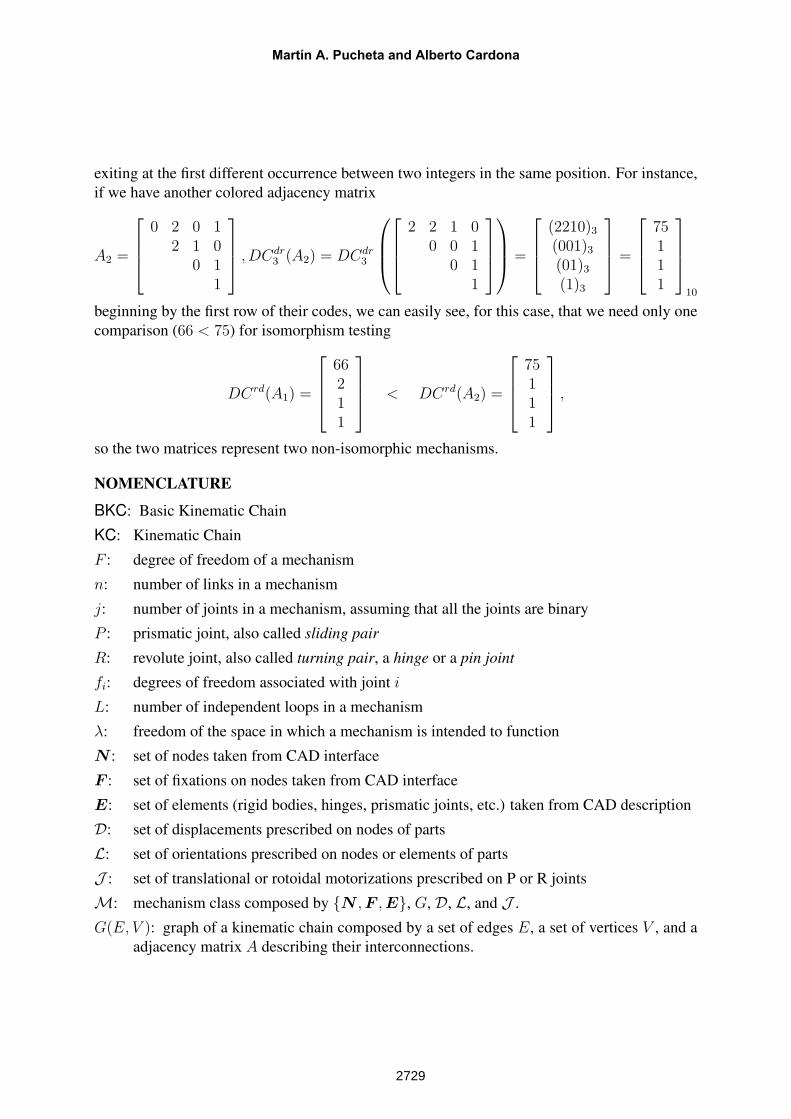
exiting at the first different occurrence between two integers in the same position. For instance,if we have another colored adjacency matrix
A2 =
0 2 0 1
2 1 00 1
1
, DCdr3 (A2) = DCdr
3
2 2 1 00 0 1
0 11
=
(2210)3
(001)3
(01)3
(1)3
=
75111
10
beginning by the first row of their codes, we can easily see, for this case, that we need only onecomparison (66 < 75) for isomorphism testing
DCrd(A1) =
66211
< DCrd(A2) =
75111
,
so the two matrices represent two non-isomorphic mechanisms.
NOMENCLATURE
BKC: Basic Kinematic Chain
KC: Kinematic Chain
F : degree of freedom of a mechanism
n: number of links in a mechanism
j: number of joints in a mechanism, assuming that all the joints are binary
P : prismatic joint, also called sliding pair
R: revolute joint, also called turning pair, a hinge or a pin joint
fi: degrees of freedom associated with joint i
L: number of independent loops in a mechanism
λ: freedom of the space in which a mechanism is intended to function
N : set of nodes taken from CAD interface
F : set of fixations on nodes taken from CAD interface
E: set of elements (rigid bodies, hinges, prismatic joints, etc.) taken from CAD description
D: set of displacements prescribed on nodes of parts
L: set of orientations prescribed on nodes or elements of parts
J : set of translational or rotoidal motorizations prescribed on P or R joints
M: mechanism class composed by {N , F , E}, G, D, L, and J .
G(E, V ): graph of a kinematic chain composed by a set of edges E, a set of vertices V , and aadjacency matrix A describing their interconnections.
Martín A. Pucheta and Alberto Cardona
2729
A: adjacency matrix
ei: edge of a graph G
vi: vertex of a graph G
d(vi): degree of the vertex i, or number of vertices connected to the vertex i
d(vi, vj): distance between vertex i and vertex j
C(vi): vertex class
p: permutation vector
DC(Ai): Degree Code of the adjacency matrix i
DCdb (Ai): Diagonally Extended Degree Code of the adjacency matrix i in base b.
DCdrb (Ai): Diagonally Extended Degree Code of the adjacency matrix i in base b computed by
rows.
MECOM 2005 – VIII Congreso Argentino de Mecánica Computacional
2730