infinitesimal mechanisms analogy for immobilization¬nitesimal mechanisms analogy for...
TRANSCRIPT
Infinitesimal Mechanisms Analogy forImmobilization
Ramakrishna K.Department of Mechanical Engineering
Indian Institute of ScienceBangalore 560 012, INDIA
Dibakar SenDepartment of Mechanical Engineering
Indian Institute of ScienceBangalore 560 012, INDIA
Abstract—This paper presents an analogy between a planarimmobilized object with point contacts and a platform typefirst-order infinitesimal planar mechanism. It is proposed that asmooth immobilized object has similar mobility characteristicswith the immobilized platform in a first-order infinitesimalmechanism. It is shown that through the classical higher pairlower pair replacement, a first-order infinitesimal mechanismis generated from second-order form-closed pair. Procedure tosynthesize immobilized objects from a first-order infinitesimalmechanism is detailed and implementation is shown for twoexamples. It is observed that for a given first-order infinitesimalmechanism, multiple families of second-order form-closed pairscan be synthesized. A geometrical technique based upon thefirst-order contact of workspace boundaries of sub-chains ofthe linkage is used for determining the first-order infinitesimalmechanism configurations.
Keywords – infinitesimal mechanism; form-closure; singular-ity; immobilization
I. INTRODUCTION
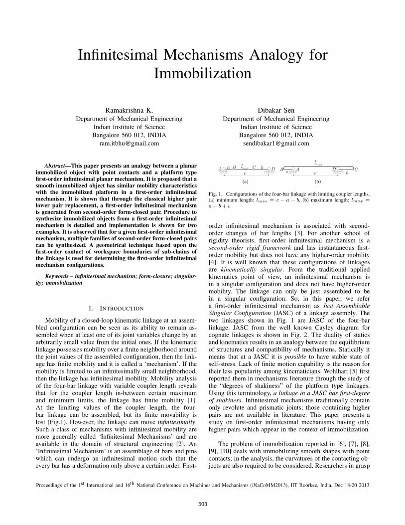
Mobility of a closed-loop kinematic linkage at an assem-bled configuration can be seen as its ability to remain as-sembled when at least one of its joint variables change by anarbitrarily small value from the initial ones. If the kinematiclinkage possesses mobility over a finite neighborhood aroundthe joint values of the assembled configuration, then the link-age has finite mobility and it is called a ‘mechanism’. If themobility is limited to an infinitesimally small neighborhood,then the linkage has infinitesimal mobility. Mobility analysisof the four-bar linkage with variable coupler length revealsthat for the coupler length in-between certain maximumand minimum limits, the linkage has finite mobility [1].At the limiting values of the coupler length, the four-bar linkage can be assembled, but its finite movability islost (Fig.1). However, the linkage can move infinitesimally.Such a class of mechanisms with infinitesimal mobility aremore generally called ‘Infinitesimal Mechanisms’ and areavailable in the domain of structural engineering [2]. An‘Infinitesimal Mechanism’ is an assemblage of bars and pinswhich can undergo an infinitesimal motion such that theevery bar has a deformation only above a certain order. First-
(a) (b)
Fig. 1. Configurations of the four-bar linkage with limiting coupler lengths.(a) minimum length: lmin = c − a − b, (b) maximum length: lmax =a+ b+ c.
order infinitesimal mechanism is associated with second-order changes of bar lengths [3]. For another school ofrigidity theorists, first-order infinitesimal mechanism is asecond-order rigid framework and has instantaneous first-order mobility but does not have any higher-order mobility[4]. It is well known that these configurations of linkagesare kinematically singular. From the traditional appliedkinematics point of view, an infinitesimal mechanism isin a singular configuration and does not have higher-ordermobility. The linkage can only be just assembled to bein a singular configuration. So, in this paper, we refera first-order infinitesimal mechanism as Just AssemblableSingular Configuration (JASC) of a linkage assembly. Thetwo linkages shown in Fig. 1 are JASC of the four-barlinkage. JASC from the well known Cayley diagram forcognate linkages is shown in Fig. 2. The duality of staticsand kinematics results in an analogy between the equilibriumof structures and compatibility of mechanisms. Statically itmeans that at a JASC it is possible to have stable state ofself-stress. Lack of finite motion capability is the reason fortheir less popularity among kinematicians. Wohlhart [5] firstreported them in mechanisms literature through the study ofthe “degrees of shakiness” of the platform type linkages.Using this terminology, a linkage in a JASC has first-degreeof shakiness. Infinitesimal mechanisms traditionally containonly revolute and prismatic joints; those containing higherpairs are not available in literature. This paper presents astudy on first-order infinitesimal mechanisms having onlyhigher pairs which appear in the context of immobilization.
The problem of immobilization reported in [6], [7], [8],[9], [10] deals with immobilizing smooth shapes with pointcontacts; in the analysis, the curvatures of the contacting ob-jects are also required to be considered. Researchers in grasp
Proceedings of the 1st International and 16th National Conference on Machines and Mechanisms (iNaCoMM2013), IIT Roorkee, India, Dec 18-20 2013
503
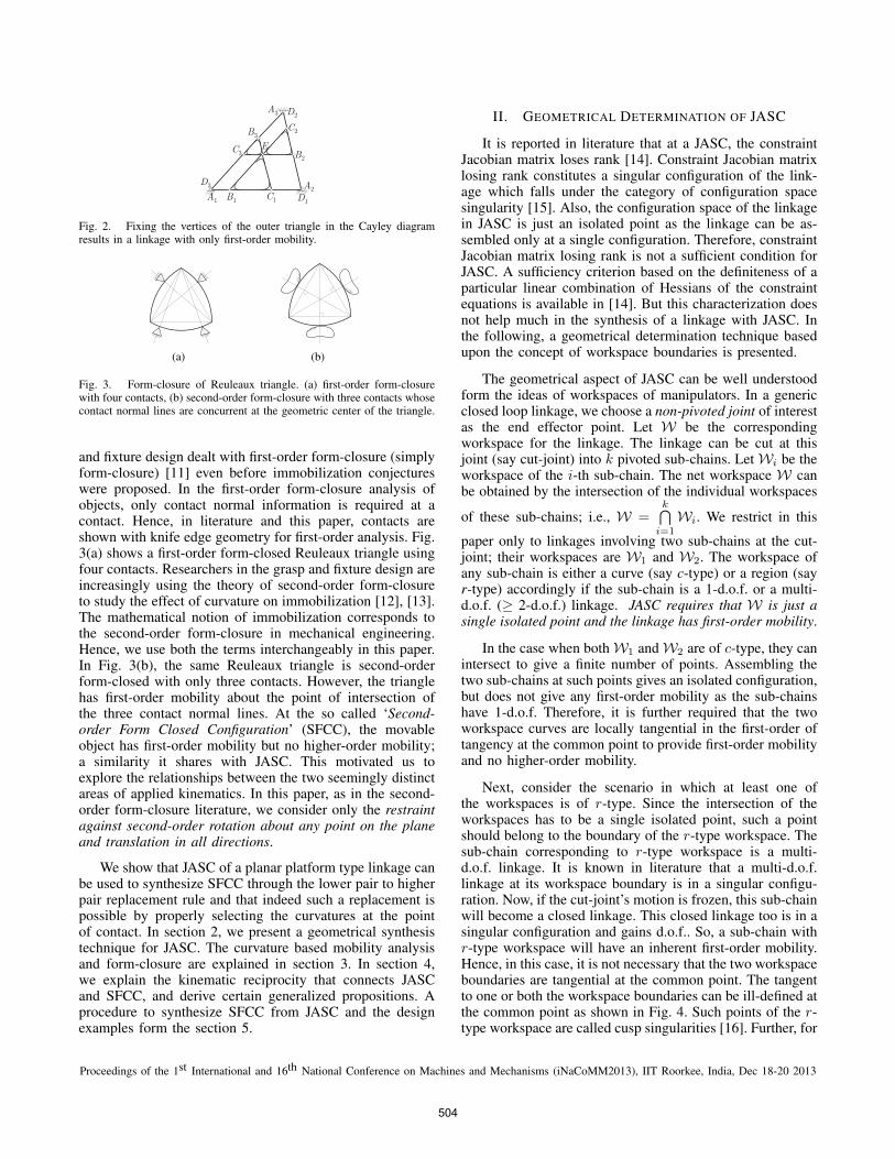
Fig. 2. Fixing the vertices of the outer triangle in the Cayley diagramresults in a linkage with only first-order mobility.
(a) (b)
Fig. 3. Form-closure of Reuleaux triangle. (a) first-order form-closurewith four contacts, (b) second-order form-closure with three contacts whosecontact normal lines are concurrent at the geometric center of the triangle.
and fixture design dealt with first-order form-closure (simplyform-closure) [11] even before immobilization conjectureswere proposed. In the first-order form-closure analysis ofobjects, only contact normal information is required at acontact. Hence, in literature and this paper, contacts areshown with knife edge geometry for first-order analysis. Fig.3(a) shows a first-order form-closed Reuleaux triangle usingfour contacts. Researchers in the grasp and fixture design areincreasingly using the theory of second-order form-closureto study the effect of curvature on immobilization [12], [13].The mathematical notion of immobilization corresponds tothe second-order form-closure in mechanical engineering.Hence, we use both the terms interchangeably in this paper.In Fig. 3(b), the same Reuleaux triangle is second-orderform-closed with only three contacts. However, the trianglehas first-order mobility about the point of intersection ofthe three contact normal lines. At the so called ‘Second-order Form Closed Configuration’ (SFCC), the movableobject has first-order mobility but no higher-order mobility;a similarity it shares with JASC. This motivated us toexplore the relationships between the two seemingly distinctareas of applied kinematics. In this paper, as in the second-order form-closure literature, we consider only the restraintagainst second-order rotation about any point on the planeand translation in all directions.
We show that JASC of a planar platform type linkage canbe used to synthesize SFCC through the lower pair to higherpair replacement rule and that indeed such a replacement ispossible by properly selecting the curvatures at the pointof contact. In section 2, we present a geometrical synthesistechnique for JASC. The curvature based mobility analysisand form-closure are explained in section 3. In section 4,we explain the kinematic reciprocity that connects JASCand SFCC, and derive certain generalized propositions. Aprocedure to synthesize SFCC from JASC and the designexamples form the section 5.
II. GEOMETRICAL DETERMINATION OF JASC
It is reported in literature that at a JASC, the constraintJacobian matrix loses rank [14]. Constraint Jacobian matrixlosing rank constitutes a singular configuration of the link-age which falls under the category of configuration spacesingularity [15]. Also, the configuration space of the linkagein JASC is just an isolated point as the linkage can be as-sembled only at a single configuration. Therefore, constraintJacobian matrix losing rank is not a sufficient condition forJASC. A sufficiency criterion based on the definiteness of aparticular linear combination of Hessians of the constraintequations is available in [14]. But this characterization doesnot help much in the synthesis of a linkage with JASC. Inthe following, a geometrical determination technique basedupon the concept of workspace boundaries is presented.
The geometrical aspect of JASC can be well understoodform the ideas of workspaces of manipulators. In a genericclosed loop linkage, we choose a non-pivoted joint of interestas the end effector point. Let W be the correspondingworkspace for the linkage. The linkage can be cut at thisjoint (say cut-joint) into k pivoted sub-chains. LetWi be theworkspace of the i-th sub-chain. The net workspace W canbe obtained by the intersection of the individual workspaces
of these sub-chains; i.e., W =k⋂
i=1
Wi. We restrict in this
paper only to linkages involving two sub-chains at the cut-joint; their workspaces are W1 and W2. The workspace ofany sub-chain is either a curve (say c-type) or a region (sayr-type) accordingly if the sub-chain is a 1-d.o.f. or a multi-d.o.f. (≥ 2-d.o.f.) linkage. JASC requires that W is just asingle isolated point and the linkage has first-order mobility.
In the case when bothW1 andW2 are of c-type, they canintersect to give a finite number of points. Assembling thetwo sub-chains at such points gives an isolated configuration,but does not give any first-order mobility as the sub-chainshave 1-d.o.f. Therefore, it is further required that the twoworkspace curves are locally tangential in the first-order oftangency at the common point to provide first-order mobilityand no higher-order mobility.
Next, consider the scenario in which at least one ofthe workspaces is of r-type. Since the intersection of theworkspaces has to be a single isolated point, such a pointshould belong to the boundary of the r-type workspace. Thesub-chain corresponding to r-type workspace is a multi-d.o.f. linkage. It is known in literature that a multi-d.o.f.linkage at its workspace boundary is in a singular configu-ration. Now, if the cut-joint’s motion is frozen, this sub-chainwill become a closed linkage. This closed linkage too is in asingular configuration and gains d.o.f.. So, a sub-chain withr-type workspace will have an inherent first-order mobility.Hence, in this case, it is not necessary that the two workspaceboundaries are tangential at the common point. The tangentto one or both the workspace boundaries can be ill-defined atthe common point as shown in Fig. 4. Such points of the r-type workspace are called cusp singularities [16]. Further, for
Proceedings of the 1st International and 16th National Conference on Machines and Mechanisms (iNaCoMM2013), IIT Roorkee, India, Dec 18-20 2013
504

(a) (b) (c)
Fig. 4. Cusp singularities of r-type workspace’s boundary providelocations where it can share only a single point with the other workspace’sboundary without being tangential to it.
(a) (b) (c)
Fig. 5. Triangular truss and its JASCs. (a) truss ABC cut at joint B, (b)external tangency of circles, (c) internal tangency of circles.
a sub-chain having r-type workspace, we have to make surethat the inherent gained d.o.f. do not result in second-ordermobility. For this, freeze the original cut-joint and again usethe same concept of workspace boundaries at a new cut-jointin the sub-chain.
Summarizing, it is derived that if none of W1 and W2 isof r-type, they have to contact in first-order of tangency fora JASC. If at least one of them is of r-type, it is sufficientthat they share only a common point on their workspaceboundaries. Further, if the common point is an ordinarypoint for both the workspace boundaries, then W1 andW2 have to contact in first-order of tangency. Using thistechnique we now determine JASC for a few linkages. Theselection of the initial cut-joint in a given linkage is such thatthe two sub-chains are familiar linkages whose workspaceboundary geometries are easily derivable.
(i) Triangular truss: In Fig. 5(a), the truss ABC is cut at thejoint B to give two pivoted links. The workspace of each ofthem is a circle whose center is at the pivot point and radiussame as link length. JASC occurs when the two circles areeither externally or internally tangential as shown in Fig.5(b) and (c) respectively.
(ii) Four-bar linkage: The four-bar linkage ABCD in Fig.6(a) can be cut at the joint C to give a pivoted dyad ABCand a pivoted link DC. The workspace of the dyad isan annular region defined by two bounding circles, viz.,inner boundary circle and outer boundary circle. The link’sworkspace is the link circle. JASCs occur in the fourtangency scenarios of the two workspaces, shown in Fig.6. In all the four cases, if the cut-joint’s motion is frozen,the dyad still has only inherent first-order mobility and nosecond-order mobility. It is only a matter of choice that joint
(a) (b) (c)
(d) (e)
Fig. 6. Four-bar linkage and its JASCs. (a) four-bar linkage ABCD cut atthe joint C, (b) outer boundary circle and link circle are externally tangent,(c) outer boundary circle and link circle are internally tangent, (d) innerboundary circle and link circle are internally tangent and dyad’s longerlink is pivoted, (e) inner boundary circle are internally tangent and dyad’sshorter link is pivoted.
C is chosen as the cut-joint. In the case of the four-barlinkage, it can be easily verified that the results are samefor the other cut-joint B.
(iii) 3-RR platform linkage: The linkage ABCDEF shownin Fig. 7(a) can be decomposed into the four-bar linkageABCDE and the pivoted link FE, both joined at thecoupler point E of four-bar linkage. The point-path of thecoupler point is the coupler curve. At a JASC, the circletraced by the pivoted link’s free end is tangential to thecoupler curve in the first-order of tangency (Fig. 7(b)). Ifthe pivot point F coincides with the center of curvature ofthe coupler curve of the four-bar linkage, then the abovecircle has second-order tangency with the coupler curve.Then the linkage loses second-order rigidity. This issue isalso mentioned in [5] which has been derived purely throughkinematic analysis. Fig. 16(a) in the Appendix shows thelocation of the center of curvature of the point-path of E ofthe same four-bar linkage ABCDE obtained by geometricconstruction. The pivot F in Fig. 7(b) is different fromthe location of the center of curvature; thus the linkageunder consideration is indeed in a JASC. In decomposingthe linkage we could have cut the chain at joints B or Ceither. This raises an issue whether the check for second-order mobility and consequently the synthesis of JASCis dependent upon the four-bar sub-chain chosen. In theAppendix, it is argued through geometric constructions thatthe second-order mobility check is independent of the cut-joint.
Now consider the linkage shown in Fig. 8 where the threeline-of-joints of the binary links 1, 3, and 5 are concurrent
Proceedings of the 1st International and 16th National Conference on Machines and Mechanisms (iNaCoMM2013), IIT Roorkee, India, Dec 18-20 2013
505

(a) (b)
Fig. 7. 3-RR platform linkage and a JASC. (a) linkage ABCDEF cutat the joint E, (b) coupler curve and the circle have first-order contact.
Fig. 8. Four-bar type linkage with two coupler links in a singularconfiguration.
at point P24. Suppose that either one of the links 3 or 5 isremoved. Then, for the resulting four-bar linkage, P24 is thevelocity pole for the relative motion between links 2 and 4,in spite of which ever link is deleted. So, the simultaneouspresence of the links 3 and 5 does not inhibit the linkagein having first-order mobility. Now, using the concept ofworkspaces of sub-chains it is difficult to answer whetherthis linkage is in a JASC. But recognizing that this linkageis a kinematic inversion of a 3-RR platform linkage with abinary link fixation, makes it convenient to verify whetherthat 3-RR platform linkage is in a JASC.
(iv) Two platform linkage: The linkage ABCDEFGHIJshown in Fig. 9(a) can be cut at the joint F to give sub-chains ABCDEF and HGIJF . Sub-chain ABCDEF isa four-bar linkage with a dangling link on coupler and itsworkspace is of r-type. Sub-chain HGIJF is a four-barlinkage whose workspace is of c-type. In Fig. 9(b), at an or-dinary workspace boundary point of linkage ABCDEF , thetwo workspace boundaries of the sub-chains are tangentialin the first-order of tangency. Further, freezing the motionof joint F , the resulting 3-RR platform linkage ABCDEFdoes not have second-order mobility which is verified by themethod employed in the previous example.
III. RELATIONSHIP BETWEEN CURVATURE ANDMOBILITY
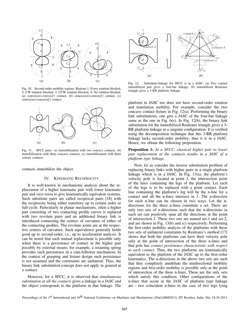
In this section, the results of the curvature based mobilityanalysis are reproduced from [13] and contextualized. Thethree types of contacting geometries are shown in Fig. 10.These three types belong to two classes, viz., convex (Fig.10(a)) and concave class (Fig. 10(b) and (c)). The movableand fixed curve are labeled m-curve and f -curve respectively.
(a) (b)
Fig. 9. (a) Two platform linkage, (b) tangency of workspaces.
The centers of curvature of f -curve and m-curve are Cf andCm respectively. The contact normal line is referred to as n-line and the direction of positive yf -axis along the n-line isreferred to as n-direction. The n-direction is in the directionaway from the material side of f-curve at a contact. For aconvex contact the n-direction is from Cf towards Cm andfor a concave contact it is the opposite.
For any point of contact, the plane is partitioned intofour regions (Fig. 10) based on the mobility characteristicsof each point on the plane for a second-order rotation aboutthat point. For a point in region 1, both clockwise (CW)and counterclockwise (CCW) rotations are blocked. Region2 contains points for which there is penetration for CWrotation and separation for CCW rotation. In mobility region3, the situation is opposite. In region 4, there is no penetra-tion for both directions of rotation. Region 4 contains pointsas rotation centers with bidirectional separation mobility aswell as those with bidirectional contact preserving mobility.While regions 1 and 4 are the partitions of the n-line; regions2 and 3 are the two half-planes on either side of the n-line.The region delimited by the centers of curvature is eitherregion 1 or region 4 depending upon the geometry of thecurves at the point of contact. The complementary regionon the n-line is of the alternate type. If the rotation centercoincides with either Cf or Cm, the contact between thecurves will be preserved for the second-order rotation aboutthis point; thus m-curve remains adhered to the f -curve.Translation is considered as the asymptotic rotation aboutthe point at infinity along a line orthogonal to the directionof translation and the four mobility regions unambiguouslycharacterize this asymptotic point. The regions 2 and 3 aresimilar to the unidirectional mobility regions partitioned bythe n-line in Reuleaux’s first-order analysis [17]. Second-order mobility analysis partitions the contact persistencevelocity poles along the n-line into regions 1 and 4.
In a multiple contacts scenario, the net mobility is theintersection of the mobility obtained for the point withrespect to each contact. Thus, a contact configuration forwhich region 1 covers the whole plane corresponds to aSFCC and the object is immobilized. Synthesis of suchcontact configurations have been dealt with in [13]. Fig.11(a) illustrates a two-contact immobilization. In Fig. 11(b)and (c), concurrent n-lines of three concave and convex
Proceedings of the 1st International and 16th National Conference on Machines and Mechanisms (iNaCoMM2013), IIT Roorkee, India, Dec 18-20 2013
506
(a) (b) (c)
Fig. 10. Second-order mobility regions. Regions 1: Every rotation blocked,2: CW rotation blocked, 3: CCW rotation blocked, 4: No rotation blocked.(a) convex(m)-convex(f ) contact, (b) concave(m)-convex(f ) contact, (c)convex(m)-concave(f ) contact.
(a) (b) (c)
Fig. 11. SFCC pairs. (a) immobilization with two concave contacts, (b)immobilization with three concave contacts, (c) immobilization with threeconvex contacts.
contacts immobilize the object.
IV. KINEMATIC RECIPROCITY
It is well-known in mechanisms analysis about the re-placement of a higher kinematic pair with lower kinematicpair and vice-versa to give kinematically equivalent systems.Such substitute pairs are called reciprocal pairs [18] withthe reciprocity being either transitory up to certain order orfull-cycle. Particularly in planar mechanisms, often a higherpair consisting of two contacting profile curves is replacedwith two revolute pairs and an additional binary link isintroduced connecting the centres of curvature of either ofthe contacting profiles. The revolute joints are at the respec-tive centres of curvature. Such equivalence generally holdsgood up to second-order, i.e., up to acceleration analysis. Itcan be noted that such mutual replacement is possible onlywhen there is a persistence of contact in the higher pairpossibly by external means; for example, a retaining springprovides such persistence in a cam-follower mechanism. Inthe context of grasping and fixture design such persistenceis not assumed and the constraints are unilateral. Thus, thebinary link substitution concept does not apply in general ata contact.
However, for a SFCC, it is observed that simultaneoussubstitution at all the contacts gives a linkage in a JASC andthe object corresponds to the platform in that linkage. The
(a) (b)
Fig. 12. Substitute-linkage for SFCC is in a JASC. (a) Two contactimmobilized pair gives a four-bar linkage, (b) immobilized Reuleauxtriangle gives a 3-RR platform linkage.
platform in JASC too does not have second-order rotationand translation mobility. For example, consider the twoconcave contact fixture in Fig. 12(a). Performing the binarylink substitutions, one gets a JASC of the four-bar linkagesame as the one in Fig. 6(e). In Fig. 12(b), the binary linksubstitution for the immobilized Reuleaux triangle gives a 3-RR platform linkage in a singular configuration. It is verifiedusing the decomposition technique that this 3-RR platformlinkage lacks second-order mobility; thus it is in a JASC.Hence, we obtain the following proposition.
Proposition 1: At a SFCC, classical higher pair to lowerpair replacement at the contacts results in a JASC of aplatform type linkage.
Now, let us consider the inverse substitution problem ofreplacing binary links with higher pairs in a single platformlinkage which is in a JASC. In Fig. 13(a), the platform’svelocity pole is located at point I, the intersection pointof the lines containing the legs of the platform. Let eachof the legs is to be replaced with a point contact. Eachline containing the platform’s leg will be the n-line for acontact and all the n-lines intersect in I . The n-directionfor each n-line can be chosen in two ways. Let the n-directions for the three n-lines constitute a set. There areonly two sets of n-directions such that the n-directions ineach set can positively span all the directions at the pointof intersection I . These two sets are named set-1 and set-2,and are shown in Fig. 13(b) and (c) respectively. Performingthe first-order mobility analysis of the platforms with thesetwo sets of unilateral constraints by Reuleaux’s method [17]shows that both the platforms can have their velocity poleonly at the point of intersection of the three n-lines andthat pole has contact persistence characteristic with respectto each contact. Thus, the two platforms are kinematicallyequivalent to the platform of the JASC up to the first-orderkinematics. The n-directions in the above two sets are suchthat they completely annihilate the unidirectional mobilityregions and first-order mobility is possible only at the pointof intersection of the three n-lines. These are the only setswhich satisfy this condition. Other configurations of then-lines that occur in the JASC of platform type linkageare : two coincident n-lines in the case of two legs lying
Proceedings of the 1st International and 16th National Conference on Machines and Mechanisms (iNaCoMM2013), IIT Roorkee, India, Dec 18-20 2013
507

(a) (b) (c)
Fig. 13. First-order kinematically equivalent platforms. (a) platform of a3-RR linkage in a JASC, (b) platform with set-1 n-directions, (c) platformwith set-2 n-directions.
on the same line and three parallel n-lines in the case ofthree parallel legs. For two coincident n-lines, the two n-directions are chosen to be oppositely oriented to annihilatethe unidirectional mobility regions and the velocity polecan lie only on the n-line. Here too, we get two sets ofn-directions. For similar annihilation in the case of threeparallel n-lines, the n-direction of the middle n-line shouldbe opposite to that of the other two; meaning the two non-middle n-lines have the same n-direction. Even in this caseonly two sets of n-directions are possible. Hence, in all thecases discussed, there are only two sets of n-directions. Thenext proposition summarizes this replacement of bilateralconstraints with unilateral constraints for a certain kind ofequivalence in a particular case.
Proposition 2: At a JASC of a planar platform typekinematic linkage, all the lower pair joints connecting theplatform to the base through legs can be replaced with pointcontacts with the platform by choosing the contact directionsin such a way that the first-order kinematic equivalence ismaintained and the contacts persist for such equivalencewithout any external means.
Now coming to the full contact geometry, each n-direction with two centers of curvature along the n-linegive the contact class. Accordingly, all the contacts in Fig.13(b) and (c) are required to be concave and convex classrespectively. It is shown in [13] that for three concurrentn-lines with n-directions like the ones in Fig. 13(b) and(c), the first and second-order mobility analysis differ onlyabout the mobility characteristic of the point I. So, we aresure that the second-order rotation about any point of theplane except point I is blocked. The second-order mobilityanalysis reveals that the bidirectional rotation about I isallowed for the platform with the n-directions and centersof curvature as shown in Fig. 13(c), but it is blocked for theplatform in Fig. 13(b). The platform in Fig. 13(a) too doesnot have any second-order rotation about any point on theplane. Generalizing the above observations, the followingproposition can be stated.
Proposition 3: For an equivalent system mentioned inproposition 2, with centers of curvature of contacting curvesat the erstwhile joint locations, and the contact class beingdefined by the centers of curvature and the n-direction, if thesecond-order rotation about point/s of intersection of the n-
lines is blocked, then the contacting curves form a SFCC.
In the next section, we give in detail a procedure to synthe-size SFCC from JASC based upon the above propositions.
V. SYNTHESIS OF SFCC FROM JASC
This section deals with the systematic procedure ofsynthesizing SFCC from a JASC of single platform typelinkage. The synthesis steps are given below.
A: Draw the n-lines
Locate the platform and identify the legs (binary links)connecting it to the base. The two hinge points of a binarylink will be the centers of curvature (Cm and Cf ) forthe curves at the contact which is to be introduced inplace of that link. The line joining Cm and Cf gives thecorresponding n-line.
B: Choose the directions for n-lines
This step is based on proposition 2. If two n-lines arecoincident, choose mutually opposite directions for the twon-directions. For three concurrent n-lines, choose the n-directions such that they positively span all the directions.Finally, in the case of three parallel n-lines, the two non-middle n-lines should have same n-direction and the middleone has the opposite direction. At this stage one gets twosets of n-directions.
C: Determine the class of each contact
For each of the n-direction in a particular set obtainedfrom step-B, the class of the contact (convex or concave)is decided by the orientation of the n-direction w.r.t. Cm
and Cf . For a convex contact the n-direction is from Cf
towards Cm and for a concave contact it is the opposite.
D: Check whether the point/s of intersection of the n-lines belong to region 1 of second-order mobility w.r.t.at least one of the n-lines
Once the contact classes for all the n-directions are obtained,check whether the point/s of intersection of the n-lines(single point or points on coincident lines or a point atinfinity) belong to region 1 of second-order mobility analysisfor at least one of the n-lines. If the check fails, then repeatthis step for another set of n-directions.
E: Choose the contact points along the n-lines
For a concave class contact, the point of contact shouldnot belong to the line segment delimited by the centers ofcurvature; it is the opposite for convex contact. Once thecontact point is chosen, the local geometry is defined by thetwo centers of curvature.
F: Connect the individual curve pieces to get closed m-curve and f -curve
It is quite possible that for a certain feasible set ofn-directions in step-B, one might not get a feasible SFCCin step-D. All the designs having same nature of contact
Proceedings of the 1st International and 16th National Conference on Machines and Mechanisms (iNaCoMM2013), IIT Roorkee, India, Dec 18-20 2013
508

geometry for each corresponding n-line, but differentlocations of contact points, can be put into a single family.If the contact class for a given n-direction is concave,then there are two possibilities for the type of contactgeometry. So, every concave class contact doubles thenumber of families of design solutions for a given JASC.Also, by mere selection of different location of contactpoints while keeping the contact types same, it may sohappen that the connected m-curve may lie entirely insideor outside the f -curve. This further results in a separatefamily. Hence, it is possible that at the end of step-F, onemight obtain multiple families of SFCC designs for a singleset of contact-directions obtained from step-B. The aboveprocedure is applied to two examples given below.
Example 1: Four-bar linkageLet us synthesize SFCC from the linkage shown in Fig.6(b). The steps are shown in Fig. 14. Step-B yields two setsof n-directions. In step-C, the n-directions with the givencenters of curvature imply that the both the contacts in set-1and set-2 are concave and convex class respectively. Sincethe two line segments, delimited by the centers of curvature,do not overlap, the only way that the entire line containingthese two segments belongs to region 1 is that neither ofthe contacts should be of convex class. So SFCC cannotbe synthesized with the n-directions of set-2. Only set-1yields SFCC which are shown in Fig. 14(c). Since the twocontacts have to be concave, minimum four (2 × 2) designfamilies are readily possible. But additional designs areobtained by choosing the contact locations differently. Thusthe number of distinct families of designs is seven. In Fig.14(c), the corresponding contacts in designs (i) and (iv)have same nature of contact geometry but different contactlocations. Same is the case with (v) and (vi), (ii) and (vii).
Example 2: 3-RR platform linkageFor the linkage in Fig. 13(a), step-B gives two sets ofn-directions shown in Fig. 13(b) and (c). In step-C, all thecontacts for n-directions of set-1 and set-2 are to be concaveand convex respectively. From step-D, it is obtained thatpoint I belongs to region 1 w.r.t every contact for a concavecontact scenario but belongs to region 4 in the case ofconvex contact. So only set-1 generates SFCC and the otherset does not. A representative set of the design families isshown in Fig. 15.
The above examples show that for a given JASCmore than one family of SFCC are obtained. In otherwords, multiple families of SFCC give the same JASC. Inthis sense JASC of linkage provides a central concept ingrouping and distinguishing various SFCC apart from theirsynthesis.
VI. CONCLUSION
SFCC can be seen as platform type first-order infinitesi-mal mechanism with only higher pairs. There is a symbiotic
relationship between the first-order infinitesimal mechanismsand second-order form closed configurations which has beenhitherto unexplored in the mechanisms literature. JASCoffers a route to the designer for synthesizing complexSFCC configurations. A geometrical technique is presentedfor obtaining JASC of a linkage assembly. The concept ofequivalent JASC is useful in grouping various SFCC designs.
APPENDIX
Geometric proof for independence of cut-joint in 3-RR platform linkage: For the same linkage in Fig. 7(b),consider now the scenario when F coincides with the centerof curvature of coupler path of point E belonging to thefour-bar sub-chain ABCDE. In Fig. 16(a), point F is nowlocated using Aronhold’s construction for path-curvature[18] for the same four-bar linkage. For this location of pivotF , consider the four-bar linkage FECDB with B as couplerpoint (Fig. 16(b)). Again using the same construction, thecenter of curvature of the point-path of coupler point B islocated at Ao. The construction steps in the second case traceback the original construction lines and angles. So, we havePo = Q and Qo = P , which results in Ao = A. Hence, thecenter of curvature of the point-path of coupler point B islocated at A. A similar result can be derived for the four-bar chain ABEFC. This shows that if the analysis of thedecomposed sub-chains at a cut-joint results in the second-order mobility, then decomposition at any another cut-jointtoo will result in the same. Now using the transposition logic,a similar statement can be made about absence of second-order mobility.
REFERENCES
[1] C. H. Suh and C. W. Radcliffe, Kinematics and Mechanisms Design,NY: John Wiley and Sons, 1978, pp. 114-117.
[2] E. N. Kuznetsov, Underconstrained Structural Systems, Berlin:Springer-Verlag, 1991.
[3] C. R. Calladine and S. Pellegrino, “First-order infinitesimal mecha-nisms,” Int. J. Solids Structures, vol. 27, pp. 913-928, 1995.
[4] R. Connelly and W. Whiteley, “Second-order rigidity and prestressstability for tensegrity frameworks,” SIAM Journal on DiscreteMathematics, vol. 9, pp. 453-491, 1996.
[5] K. Wohlhart, “Degrees of shakiness,” J. Mech. Mach. Theory, vol.34, pp. 1103-1126, 1999.
[6] W. Kuperberg, “Problems on polytopes and convex sets,” DIMACSWorkshop on Polytopes, pp. 584-589, 1990.
[7] J. Bracho, L. Montejano, and J. Urrutia, “Immobilization of smoothconvex figures,” Geometiae Dedicata, vol. 53, pp. 119-134, 1994.
[8] J. Bracho, D. Mayer, H. Fetter, and L. Montejano, “Immobilizationof solids and mondriga quadratic forms,” J. London Math. Soc., vol.2, pp. 189-200, 1995.
[9] D. Mayer-Foulkes, “Immobilization of smooth convex figures: someextensions,” J. Geom., vol. 60, pp. 105-112, 1997.
[10] J. Czyzowicz, I. Stojmenovic, and J. Urrutia, “Immobilizing a shape,”Int. J. Comp. Geo. and Applications, vol. 9, pp. 181-206, 1999.
[11] B. Dizioglu and K. Lakshminarayana, “Mechanics of form closure,”Acta Mechanica, vol. 52, pp. 107-118, 1984.
[12] E. Rimon and J. Burdick, “A configuration space analysis of bodiesin contact-II. 2nd order mobility,” J. Mech. Mach. Theory, vol. 30,pp. 913-928, 1995.
Proceedings of the 1st International and 16th National Conference on Machines and Mechanisms (iNaCoMM2013), IIT Roorkee, India, Dec 18-20 2013
509

(a) (b)
(c)
Fig. 14. SFCC from JASC of a four-bar linkage. (a) legs replaced with n-lines, (b) two sets of n-directions, (c) SFCCs for set-1.
(a) (b) (c) (d)
Fig. 15. SFCC designs from JASC of a 3-RR platform linkage.
[13] K. Ramakrishna and D. Sen, “Curvature based mobility analysisand form closure of smooth planar curves with multiple contacts,”Proc. of 15th National Conference on Machines and Mechanisms(NaCoMM 2011), IIT Madras, Chennai, India, 2011.
[14] E. N. Kuznetsov, “Systems with infinitesimal mobility: Part I-Matrixanalysis and first-order infinitesimal mobility,” Trans. of ASME J.Appl. Mech., vol. 58, pp. 513-519, 1991.
[15] F. C. Park and J. W. Kim, “Singularity analysis of closed kinematicchains,” Trans. of ASME J. Mech. Des., vol. 121, pp. 32-38, 1999.
[16] D. Sen and T. S. Mruthyunjaya, “A centro-based characterization ofsingularities in the workspace of planar closed-loop manipulators,”J. Mech. Mach. Theory, vol. 33, pp. 1091-1104, 1998.
[17] M. T. Mason, Mechanics of Robotic Manipulation, Cambridge: MITpress, 2001, pp. 33.
[18] K. H. Hunt, Kinematic Geometry of Mechanisms, Oxford: OxfordUniversity press, 1978.
(a) (b)
Fig. 16. Geometric construction for locating the center of curvature ofpoint-path of the coupler point. (a) center of curvature, point F , is locatedfor the path of coupler point E of the four-bar linkage ABCDE, (b)previous construction lines and angles are traced back for locating centerof curvature with B as coupler point of the linkage FECDB.
Proceedings of the 1st International and 16th National Conference on Machines and Mechanisms (iNaCoMM2013), IIT Roorkee, India, Dec 18-20 2013
510