mechanisms and states of self-stress of planar …
TRANSCRIPT

MECHANISMS AND STATES OF SELF-STRESS OF PLANAR TRUSSES USING GRAPHIC STATICS, PART II:
APPLICATIONS AND EXTENSIONS Allan McROBIE1*, William BAKER2, Toby MITCHELL2, Marina KONSTANTATOU1
1 Dept of Engineering, Cambridge Univ, Trumpington St, Cambridge CB2 1PZ, UK
2 Skidmore, Owings & Merrill LLP
ABSTRACT: This paper extends the overview (Mitchell et al. [11]) relating graphic statics and reciprocal diagrams to linear algebra-based matrix structural analysis. Focus is placed on infinitesimal mechanisms, both in-plane (linkage) and out-of-plane (polyhedral Airy stress functions). Each self-stress in the original diagram corresponds to an out-of-plane polyhedral mechanism. Decomposition into sub-polyhedra leads to a basis set of reciprocal figures which may then be linearly combined. This leads to an intuitively-appealing approach to the identification of states of self-stress for use in structural design, and to a natural “structural algebra” for use in structural optimisation. A 90° rotation of the sub-reciprocal generated by any sub-polyhedron leads to the displacement diagram of an in-plane mechanism. Any self-stress in the original thus corresponds to an in-plane mechanism of the reciprocal, summarised by the equation s = M* (where s is the number of states of self-stress in one figure, and M* is the number of in-plane mechanisms, including rigid body rotation, in the other). Since states of self-stress correspond to out-of-plane polyhedral mechanisms, this leads to a form of “conservation of mechanisms” under reciprocity. It is also shown how external forces may be treated via a triple-layer Airy stress function, consisting of a structural layer, a load layer, and a layer formed by coordinate vectors of the structural perimeter.
Keywords: Airy stress function, dual structures, graphic statics, Maxwell, mechanisms, projective geometry, reciprocal diagrams, reciprocal figures, self-stress, truss
1. INTRODUCTION This paper describes connections between the linear algebra approach to structural analysis and the methods that arise from reciprocal diagrams and graphic statics. Although this involves linear algebra, graph theory, Airy stress functions, polyhedra and projective geometry, the intention is to extend 19th century graphical techniques to create simple methods for structural design, yet which may even address problems difficult by standard approaches. In this paper, we restrict attention to 2D trusses.
Linear structural analysis can be summarised as solving P= KU, where the (square, symmetric) stiffness matrix K, assembled element-wise from member stiffnesses and known structural geometry, relates nodal displacements U to nodal forces P. The approach underlies most structural finite element software used in practice. The matrix
approach was strengthened by Pellegrino [12-14], Calladine [3] and others, where the decomposition BEA=K (where B,E,A are the equilibrium, elasticity and compatibility matrices) allows Singular Value Decomposition to reveal the subspace structure of the possibly-rectangular matrices B or A. This allows clear separation of equilibrium into a statically-determinate case plus a linear combination of states of self-stress, with displacements similarly decomposed into those associated with mechanisms and those involving bar extension. Problems with inverting possibly singular stiffness matrices can thereby be avoided, but – perhaps more importantly – it foregrounds how the finite element solution of a statically-indeterminate structure is only one of an infinite number of possibilities, a recognition which underpins lower bound plastic design of ductile structures (Calladine [4]). Fig. 1 is a diagrammatic representation of the linear algebra statement that

2
P=KU with BEA=K, showing how (external, nodal) displacements U and forces P=BQ are related to (internal, member) extensions V=AU and tensions Q. Static-kinematic duality is embodied in the relation A= BT.
Figure 1: Schematic illustration of P=KU for V0=0 with the decomposition BEA=K, showing how subspace
accountancy requires 2n-m-3 = b-s.
For n nodes and b bars, then nodal quantities P and U have dimension 2n and bar quantities V and Q have dimension b, as represented by the lengths of the diagonals at the diagram corners. If the nodal displacement U is a linear combination of the m mechanisms and three rigid body motions, then KU=0, leaving a 2n-m-3 dimensional space of displacements U such that KU=P≠0 as shown at the top of the diagram. Similarly if Qh is a linear combination of the s states of self-stress, then BQh=0, leaving a b-s dimensional space of bar tensions for which BQ=P≠0 as shown at the left of the diagram. The subspace of nonzero equilibrium nodal forces P thus has dimension 2n-m-3 (top of diagram) and b-s (left of diagram), illustrating Calladine’s rule[3] that 2n-m-3 = b-s.
We now develop a similar diagram for graphic statics and reciprocal diagrams, the underlying algebra having already been developed in Van Mele and Block [16] and Micheletti [10], for example. Maxwell [9] showed that if and only if the truss is the projection of a polyhedron, then a reciprocal diagram can be drawn, this being the projection of a dual polyhedron. Reciprocal diagrams can have bars parallel or perpendicular to corresponding forces, the latter convention being adopted here. Even though diagrams are 2D, that they are projections of dual polyhedra means the rules of 3D
projective geometry apply, with (points, lines, planes) in one mapping to (planes, lines, points) in the other.
Fig. 2 shows how reciprocal diagrams are related to the linear algebra framework. Nodal coordinates R = [X,Y] and bar vectors L = [Lx, Ly] are now included. Reciprocal objects are denoted by an asterisk. Since there are now two structures, original and reciprocal, there are two Fig. 1 diagrams showing P=BEAU at left (original) and right (reciprocal). Along the base of the diagram, reciprocity is represented by the identities between the states of self-stress of one and the bar lengths of the other. The tension coefficients β and β*= β-1 of Rigidity Theory connect bars L with self-stress forces Qh within each structure.
Figure 2: The relationship between reciprocal diagrams and the linear algebra description of structural analysis. The P=BEAU linear algebra framework for the original
structure (Fig. 1) appears centre left. (S-KD means Static-Kinematic Duality, and displacements U and bar forces Q are partitioned into U={Uh,Up} and Q={Qh,Qp} with Uh and Qh being mechanisms and self-stresses respectively).
We call the connectivity matrix C of the original structure, seen as a directed graph, the bar-node matrix, and its elements are 1,-1 or 0. The equation L=CR represents how bar vectors L are the difference between the coordinates R of the bar end nodes. Since the force Pi applied at node i is the sum of the forces Q in bars connecting to that node, it follows that P=CTQ, and we call CT the node-bar matrix. A second matrix, J, the face-bar matrix, lists the bars forming the edges of each face of the polyhedron whose projection gives the original structure. Again, its elements are 1,-1 or 0, with the

3
sign given by the bar direction (as contained in C) relative to the oriented area of that face. We call its transpose JT the bar-face matrix. Elementary considerations show that JC=0, a matrix of zeros. That (JC)X=0 for any X corresponds to the sum of bar length x-components Lx = CX being zero around the closed loop defined by any row of J. The node-face duality of 3D projective geometry immediately implies that the bar-node matrix C* of the reciprocal will be the bar-face matrix JT of the original. Similarly, we obtain J=(CT)*.
Bar directions may be encoded via direction cosine matrices cx=diag(cos αx)=diag(Lx/L)= diag(CX/L) and cy=diag(CY/L). Writing applied forces as the 2n𝘹𝘹1 vector P=[Px;Py] then Px=CTQx=CTcxQ gives P = BQ = [CTcx; CTcy]Q, whence B = [CTcx; CTcy]. Note that writing P as 2n𝘹𝘹1or n𝘹𝘹2 is deeper than just computational book-keeping. In the usual linear algebra 2n𝘹𝘹1 form of P=BQ, the 2n𝘹𝘹b equilibrium matrix B contains both topological (C) and geometric (cx,cy) information, with Q a b𝘹𝘹1 matrix of scalar bar forces. The reciprocal description uses the n𝘹𝘹2 form P=CTQ with the n𝘹𝘹b matrix CT containing only topological information. Geometric information is then contained in Q, which is now a
b𝘹𝘹2 matrix of the components of bar force vectors. Whilst the subspace structures of B and A give information about self-stresses and mechanisms, those of C and J do not. (To simplify notation, the symbols P and Q have been used to denote both single and double column forms, with the meaning determined by context).
2. THE VECTOR SPACE OF STATES OF SELF-STRESS A statically-indeterminate original structure has, in general, a family of reciprocal diagrams. If the original has s degrees of statical indeterminacy then there is an s-dimensional family of reciprocal diagrams forming an s-dimensional vector space. For example, the structure in Fig.3 (based on Maxwell [9] Figs. 5/V) is the projection of an octahedron. The outer triangle may be taken as the z=0 base plane, and any point thereon can define the origin at which all normals to the polyhedral stress function faces will be based. The normal to the z=0 base plane intersects the reciprocal plane z=1 at the reciprocal origin (x*,y*,1) = (0,0,1). Since the outer nodes remain on the z=0 plane, there remain three free nodes {1,2,3}.
Figure 3: Reciprocal basis diagrams from local Airy polyhedra. The original supports 3 independent local stress functions, linear combinations of which lead to more general reciprocals. Faces of the basis reciprocals Q1-3 appear triangular, yet are dual to original nodes of valency 4. In each case a fourth bar of zero length at the reciprocal origin (grey) connects nodes dual to those (white) faces outside the (coloured) zone of influence. Graphical construction of h1Q1+h2Q2+h3Q3
scales each basis reciprocal and adds vectors emanating from the (grey) origin to the nodes of appropriate colour. More elegantly, scaled stress functions are added (right), with face normals defining reciprocal nodes.

4
Because the mesh is triangulated, these can be raised independently to form local pyramidal stress functions ψi. (Strictly, out-of-plane displacements generate polyhedra, whilst stress functions involve force units, but here we identify the two). Origin-based normals to the pyramid faces define the nodes of the sub-reciprocal diagrams Qi on the z=1 plane. That these nodes can be raised independently forms the basis of the resulting vector space of reciprocal diagrams.
Linear combinations of the basis reciprocals can be created by raising the inner nodes simultaneously, creating the stress function ψ=h1ψ1+h2ψ2+h3ψ3 whose normals define the reciprocal diagram Q=h1Q1+h2Q2+h3Q3. In this case, the reciprocal is the projection of a (topological) cube, this being the polyhedral dual of the original octahedron. Each of the six faces of the (flattened) cube is a four-bar linkage.
3. MECHANISMS Reciprocal diagrams represent states of self-stress which form the null-space of the equilibrium matrix B of the original structure (see for example Van Mele and Block [16], Micheletti [10]). Given that the compatibility matrix A=BT, it is unsurprising that reciprocals also provide information about the null-space of A, which contains the mechanisms.
Fig. 4 (based on Maxwell [9] Fig. 4/IV) shows the projection of a hexahedron. Two independent states of self-stress Q1 and Q2 may be created by raising the inner nodes 1 and 2. Consider a linear combination Q=h1Q1+h2Q2 having the diagram
shown (centre). Consider also the self-stress (h1+g)Q1+h2Q2 created by further raising the node 1 associated with the reciprocal basis diagram Q1. This additional out-of-plane flexing of the original polyhedron only affects the nodes dual to the faces involved in Q1. (We use the word “flexing” to describe changing a stress function, since polyhedral stress functions can be viewed as small displacement out-of-plane origami mechanisms). Since each diagram is reciprocal to the original structure, it follows that corresponding members are perpendicular to those in the original structure, and are thus mutually parallel. We call such a motion an offset as per Mitchell et al. [11] (it may also be referred to as a glide, and Crapo and Whiteley [5] use the term parallel drawing). Such a family of offsets corresponds to a 1D family of states of self-stress, parameterized by the extra flexing g.
Consider the reciprocal displacements U* caused by a small extra flexing g=δh of node 1, causing an offset from Q to Q+δQ, with δQ=Q1δh. The reciprocal bar vectors L*=Q change by δL*=δQ. The reciprocal bar extensions are V*=l*.δL*= q.δQ (lower case denoting unit vectors), and since this is an offset, the δQ are parallel to the Q. If, instead, the displacements U* are rotated by 90° it follows that the corresponding changes in the reciprocal bar vectors Q will be perpendicular to the Q, i.e. q.rot90(δQ) = 0. That is, the rotated displacements generate no bar extensions and thus correspond to an infinitesimal in-plane mechanism. Although demonstrated by example, the result is general: rotating an offset by 90° generates an in-plane mechanism.
Figure 4: 90° rotation of an offset giving a mechanism.

5
Figure 5: Mechanisms by graphical analysis. Bars in the offset (centre) and original (left) are parallel. Nodal vectors (blue, lower centre) from the pin support 1 are rotated and added to their corresponding nodes to obtain the mechanism (right).
Fig. 5 illustrates this, and yet without constructing the reciprocal. The structure (left) contains a four-bar linkage, but boundary conditions complicate matters. The offset family involves extrusion of bars g and i whilst keeping h parallel to its original (top centre). The pin at node 1 (aed) will be the zero-displacement origin and the roller at node 5 requires the displacement there to be perpendicular to the reaction T. Selecting that offset (bottom centre) which has the hi (node 5) intersection on a line passing through the origin 1 and parallel to the reaction T ensures that, once rotated, the displacement at node 5 will be perpendicular to T. Vectors from the origin to the nodes, when rotated through 90° and applied to their nodes, give the infinitesimal mechanism (right).
4.SELF-STRESS/MECHANISM RECIP-ROCAL CORRESPONDENCE Since rotating an offset gives an infinitesimal mechanism, and each offset corresponds to flexing an Airy sub-polyhedron associated with an independent state of self-stress, we have established that s=M* and s*=M, where s, M and s*, M* are the number of independent states of self-stress and mechanisms in the original and reciprocal respectively. That is, we have the 1-to-1 correspondences
State of self-stress ↔ local Airy sub-polyhedron ↔ reciprocal offset ↔ reciprocal mechanism.
Subspaces of self-stress states and mechanisms are thus isomorphic, as illustrated in Figure 6.
Figure 6: The isomorphisms between the subspaces of self-stress states and those of mechanisms.
The 1-to-1 correspondence between states of self-stress and polyhedra was established in Part I, (Mitchell et al. [11]). The correspondence between polyhedra and offsets follows immediately from the node-face duality of 3D projective geometry, in that the tilting of polyhedral faces corresponds to the motion of reciprocal nodes, and vice versa. The correspondence between offsets and mechanisms follows from the analysis of the previous section, via the interchangeability of offset displacements and their 90° rotations.
There is a technicality if only two (non-collinear) bars meet at a node, since they would then carry zero force, their reciprocals would have zero length, and whilst there exists a plane reciprocal to that node, the “face” on that plane could have zero area. The middle correspondence between polyhedra and offsets is then difficult to establish. Whilst it is

6
nevertheless possible to consider states of self-stress in bars of zero length, we leave such considerations for the future, and - like Maxwell [9] - analysis here is restricted to those cases where each node connects at least three bars.
For any reciprocal figure, an obvious offset rescales the whole diagram relative to a fixed origin. This corresponds to additional proportional tilting of the planes/normals defining the reciprocal points. Rotating this offset through 90° thus corresponds to a rigid body rotation of the diagram about the origin. The M*-dimensional vector space of reciprocal mechanisms thus contains this rigid body rotation. For example, in Fig. 4 earlier, separate flexing of self-stresses Q1 and Q2 caused offsets involving only the inner and outer triangles respectively. The corresponding mechanisms thus rotate inner and outer triangles separately, but there is a linear combination which rotates both triangles to give a rigid body rotation. That linear combination is Q=h1Q1+h2Q2, the self-stress drawn. Usually, when counting mechanisms (as in Fig. 1), the number of mechanisms m does not include rigid body rotation. Here though, it does. M* is thus one greater than m*, giving s=m*+1 (and likewise s*= m+1).
Since s=M* and s*=M, then reversing one and adding gives s+M = s*+M*. Subtracting the rigid body rotation in each, this may also be expressed as
s+m = s*+m*.
That is, the sum of the number of states of self-stress and mechanisms is preserved under reciprocity. Since each independent state of self-stress corresponds to an independent out-of-plane polyhedral mechanism, we thus obtain a form of “conservation of mechanisms” (out-of-plane polyhedral and in-plane linkage-like) under reciprocity.
5. EXTERNAL FORCES Focus thus far has been on reciprocal diagrams (as per Maxwell [9]), with states of self-stress giving graphical access to the null-space of the equilibrium matrix B and – via rotated reciprocal offsets – to the null-space of the compatibility matrix A. The missing elements are the external forces and the nodal displacements that populate the other subspaces of A and B. Treating applied forces via graphic statics is well-known, particularly amongst
architects (e.g. Allen and Zalewski[1]), and the displacement, velocity and acceleration diagrams of graphic kinematics feature in many undergraduate mechanics courses. The intention here is to create a reciprocal description encompassing both.
The key to describing external loads is the notion of a twin-layer Airy stress function which constitutes the surface of a polyhedron. It has been described in Mitchell et al. [11] how projections of a polyhedron and its dual give the form and force diagrams. Here, the notion is extended to trusses with applied loads by partitioning the polyhedron into a load surface and a force surface. The boundary between these domains is the structural perimeter in the original and the force polygon in the dual.
In unloaded structures, the twin layer nature has the advantage of removing some bar crossings which, for a single layer stress function, would require an additional node to be inserted. Whilst inserting a node in this manner has no effect from an equilibrium perspective, it may interfere with any kinematic interpretation. When loads are applied, however, the partition of the polyhedron into structure and force surfaces means that structural nodes will typically be confined to one layer, and bar crossings will tend to require node insertion.
A closed force polygon guarantees horizontal and vertical equilibrium, but moment equilibrium is only established once the reciprocal diagrams are fully constructed, since this gives full consideration to lines of action of forces. However Rankine [15] (p140) showed that moment equilibrium is obtained if the nodes of the force polygon are related to a suitable system of lines radiating from a point. Cremona [7] called such a point the “pole”. Its location is arbitrary, as is the origin of a coordinate system. Indeed the “polar radials” are nothing more than coordinate vectors of nodes on the force polygon. By constructing the reciprocal to these radials, Cremona [7] obtained the funicular polygon which, although a force concept, exists on the original diagram. In the polyhedral interpretation, the force surface on the original consists of nothing other than the funicular polygon connected to the structural perimeter by a surrounding garland of quads formed by the lines of action of the applied forces. (Satisfaction of moment equilibrium is related to the Cesaro integral condition on the continuum Airy stress function (Mitchell et al. [11])).

7
One advantage of the funicular polygon is that it can remove troublesome infinities. The notion that parallel lines meet at “the point at infinity” is central to projective geometry, and whilst infinite polyhedra present no conceptual difficulty, they can present practical problems. Fig. 8 shows a bridge to which parallel forces are applied. Considering the reciprocal to be a form diagram, then without the funicular, equilibrium at its abutment would lead to the unsatisfying conclusion that the finite vertical force component a in A equals 0 𝘹𝘹 (∞ − ∞), since the magnitude of the forces in H and I are given by the infinite lengths of h and i. By including the funicular, as in Fig. 8 (lower right), the lines of action of applied forces have finite length, and the vertical component of the radial P from the “pole” can equilibrate with that in A. Troublesome infinities are thus removed.
The force polygon and the polar radials are reciprocal respectively to the lines of action and the funicular. Interchanging form and force gives corresponding interpretations in structural terms. That is, the dual concepts are the structural
perimeter and its coordinate vectors in one diagram, together with their reciprocals, the perimeter bar tensions and the polygon reciprocal to the coordinate vectors. This latter may be called the position funicular or the coordinate hoop. The coordinate vectors R of the structural perimeter nodes thus enter the reciprocal picture. In this dual sense, the concept of “pole” is nothing other than the origin of the nodal coordinate vectors. Much of this description can be found in Cremona [7], pp135-142. (The addition of a pole and its coordinate vectors is known as “coning” in rigidity theory, and folding along the coordinate vectors creates a cone with a polygonal base, i.e. a pyramidal surface).
The internal (non-perimeter bars) of the structure may have a complicated form, and moment equilibrium is only established after chasing both diagrams through to completion. However, this may be simplified by considering the coordinate vectors R of the perimeter nodes – temporarily – as bars. This leads to a triple layer Airy stress function, via the somewhat remarkable proposal that the diagram
Figure 7: Taking the top right as the form diagram, the finite force a in A must equilibrate with infinite forces h and i perpendicular to a. The problem is avoided by coning the force polygon: the vertical component in P can equilibrate with the force in A, and the forces in H, I, J become finite (their magnitudes given by the lengths h, i, j connecting the original to the funicular).
8
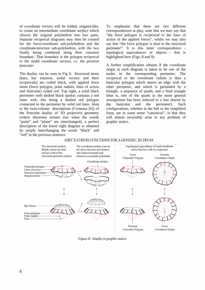
of coordinate vectors will be folded, origami-like, to create an intermediate coordinate surface which cleaves the original polyhedron into two parts. Separate reciprocal diagrams may then be created for the force/coordinate sub-polyhedron and the coordinate/structure sub-polyhedron, with the two finally being combined along their common boundary. That boundary is the polygon reciprocal to the nodal coordinate vectors, i.e. the position funicular.
The duality can be seen in Fig 8. Structural items (bars, bar tensions, nodal vectors and their reciprocals) are coded black, with applied force items (force polygon, polar radials, lines of action and funicular) coded red. Top right, a solid black perimeter with dashed black spokes contains a red inner web, this being a dashed red polygon connected to the perimeter by solid red lines. Akin to the twin-column descriptions (Cremona [6]) of the Poncelet duality of 3D projective geometry (where theorems remain true when the words “point” and “plane” are interchanged), a perfect description of the lower right diagram is obtained by simply interchanging the words “black” and “red” in the previous sentence.
To emphasise that there are two different correspondences at play, note that we may say that “the force polygon is reciprocal to the lines of action of the applied forces”, whilst we may also say that “the force polygon is dual to the structural perimeter”. It is this latter correspondence - topological equivalences of objects - that is highlighted here (Figs. 8 and 9).
A further simplification obtains if the coordinate origin in each diagram is taken to be one of the nodes in the corresponding perimeter. The reciprocal to the coordinate radials is then a funicular polygon which shares an edge with the other perimeter, and which is garlanded by a triangle, a sequence of quads, and a final triangle (that is, one of the quads in the more general arrangement has been reduced to a line shared by the funicular and the perimeter). Such configurations, whether in the full or the simplified form, are in some sense “canonical”, in that they will almost invariably arise in any problem of graphic statics.
Figure 8: Duality in graphic statics.

9
Figure 9: A loaded structure with a self-stress and a mechanism.
Fig. 9a gives an example, showing a cross-braced bay adjacent to a four-bar linkage. Although the stiffness matrix is square, this is a classic example where analysis is not straightforward by standard methods. Fig. 9b shows the simplified canonical form of the loaded structure. The (black) structural perimeter has (black dashed) coordinate spokes radiating from a perimeter node, and (red) lines of action of applied forces are connected by the simpler (red dashed) funicular. The reciprocal diagram of Fig. 9c has the same configuration of perimeter/spokes/actions/funicular, but with “red” and “black” interchanged. Note how each funicular is garlanded by the triangle-quads-triangle sequence. (In this example, the quad of the original four-bar linkage bay will remain planar when flexed, thus the reciprocal to the coordinate spoke across that quad has zero length in Fig 9c).
All that remains is to add the reciprocals of the internal bars of the structure. Node 7 is inserted to split each cross-brace in two (Fig. 9d). Since bar tensions are conserved across the node, the reciprocal consists of a parallelogram (Fig. 9e) whose opposite sides are the equal tensions in each “half” cross-brace. The bar tensions for this state of
self-stress may then be inserted into the canonical configuration (shown green in Fig. 9f) to obtain the final figure. Since the degree of self-stress is arbitrary, this parallelogram may scale arbitrarily, gliding along the lines connecting to its corners.
Whilst loads have thus far been applied to nodes on the structural perimeter, note that the perimeter need not coincide with the hull of the structural diagram, and much as the seam on a baseball partitions that surface into two domains, its plane projection can be a somewhat convoluted curve visiting points in the interior of the diagram. We leave this for future discussion.
6. STRUCTURAL ALGEBRA Section 2 demonstrated how local Airy sub-polyhedra could be added to make new polyhedra, with the result that corresponding reciprocal bar force diagrams were added vectorially. This is perhaps unsurprising, since vector addition of forces is familiar. Perhaps more unusual is that this leads to a “structural algebra” in which structures can be added. Since the original/reciprocal can be considered as a form/force or force/form pair, then a reciprocal force combination Q*new=ΣhiQ*i corresponds to constructing a linear combination of
10
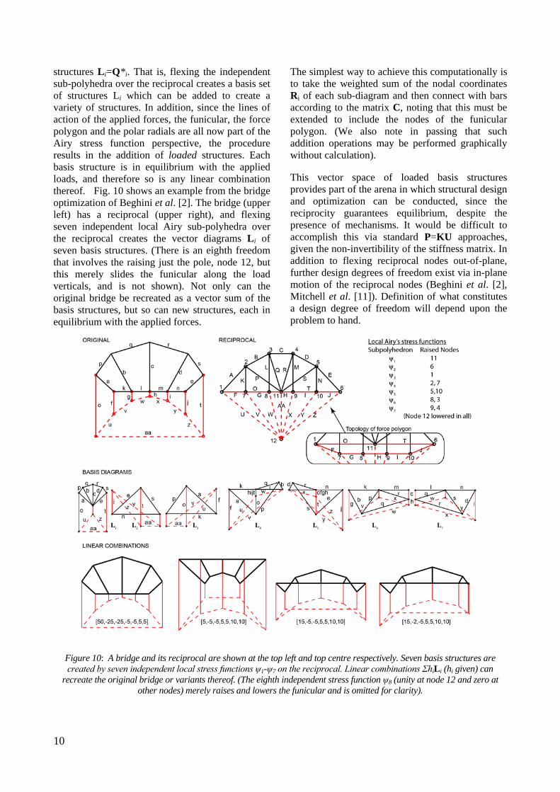
structures Li=Q*i. That is, flexing the independent sub-polyhedra over the reciprocal creates a basis set of structures Li which can be added to create a variety of structures. In addition, since the lines of action of the applied forces, the funicular, the force polygon and the polar radials are all now part of the Airy stress function perspective, the procedure results in the addition of loaded structures. Each basis structure is in equilibrium with the applied loads, and therefore so is any linear combination thereof. Fig. 10 shows an example from the bridge optimization of Beghini et al. [2]. The bridge (upper left) has a reciprocal (upper right), and flexing seven independent local Airy sub-polyhedra over the reciprocal creates the vector diagrams Li of seven basis structures. (There is an eighth freedom that involves the raising just the pole, node 12, but this merely slides the funicular along the load verticals, and is not shown). Not only can the original bridge be recreated as a vector sum of the basis structures, but so can new structures, each in equilibrium with the applied forces.
The simplest way to achieve this computationally is to take the weighted sum of the nodal coordinates Ri of each sub-diagram and then connect with bars according to the matrix C, noting that this must be extended to include the nodes of the funicular polygon. (We also note in passing that such addition operations may be performed graphically without calculation).
This vector space of loaded basis structures provides part of the arena in which structural design and optimization can be conducted, since the reciprocity guarantees equilibrium, despite the presence of mechanisms. It would be difficult to accomplish this via standard P=KU approaches, given the non-invertibility of the stiffness matrix. In addition to flexing reciprocal nodes out-of-plane, further design degrees of freedom exist via in-plane motion of the reciprocal nodes (Beghini et al. [2], Mitchell et al. [11]). Definition of what constitutes a design degree of freedom will depend upon the problem to hand.
Figure 10: A bridge and its reciprocal are shown at the top left and top centre respectively. Seven basis structures are created by seven independent local stress functions ψ1-ψ7 on the reciprocal. Linear combinations ΣhiLi (hi given) can
recreate the original bridge or variants thereof. (The eighth independent stress function ψ8 (unity at node 12 and zero at other nodes) merely raises and lowers the funicular and is omitted for clarity).
11
7. CONCLUDING REMARKS Part I of this pair of papers explained why graphic statics and kinematics remain worthy of study. Here a framework has been outlined relating the static and kinematic objects via reciprocal diagrams and Airy stress functions. Whilst much of this may have been known in the 19th century, some novel interpretations have been presented, including the s=M* identity between states of self-stress and reciprocal mechanisms (Crapo and Whiteley [5]), the treatment of external loads via the three-layer Airy stress function and the “structural algebra” for use in design and optimization. Given the correspondence between states of self-stress of planar trusses and compatible plastic yield line collapse mechanisms of slabs (Denton [8]), the methods presented here may also find application in fields beyond truss design.
REFERENCES [1] Allen E. and Zalewski,W., Form and Forces: Designing Efficient, Expressive Structures, Wiley, 2009. [2] Beghini L.L., Carrion J., Beghini A., Mazurek, A. and Baker W.F., Structural optimization using graphic statics, Structural and Multidisciplinary Optimization, 2013 [3] Calladine C.R., Buckminster Fuller’s “Tensegrity” Structures and Clerk Maxwell’s Rules for the Construction of Stiff Frames International Journal of Solids and Structures, 1978; 14: 161-172. [4] Calladine C.R., Plasticity for Engineers: Theory and Applications, Woodhead, 2000. [5] Crapo H. and Whiteley W., Spaces of stresses, projections and parallel drawings for spherical polyhedra, Beitrage zur Algebra und Geometrie, 1994; 35, 2; 259-281. [6] Cremona L., Elements of Projective Geometry, Clarendon, Oxford, 1885. [7] Cremona L., Two treatises on the Graphical Calculus and Reciprocal Figures in Graphical Statics, Oxford, 1890 (transl. Beare, T.H.). [8] Denton S.R., Compatibility requirements for yield-line mechanisms, International Journal of Solids and Structures, 2001; 38:3099-3109. [9] Maxwell J.C., On Reciprocal Figures and Diagram of Forces. Philosophical Magazine, 1864; 26:250-261. [10] Micheletti A., On generalized reciprocal diagrams for self-stressed frameworks, International Journal of Space Structures, 2008; 23(3):153-166. [11] Mitchell T., Baker W., McRobie A. and Mazurek A., Mechanisms and States of Self-stress
of Planar Trusses Using Graphic Statics, Part I: The Fundamental Theorem of Linear Algebra and the Airy Stress Function, International Journal of Space Structures 2016 (this volume). [12] Pellegrino S., Mechanics of Kinematically Indeterminate Structures. PhD, Cambridge, 1986. [13] Pellegrino S., Calladine C.R., Matrix analysis of statically and kinematically indeterminate frameworks, International Journal of Solids and Structures, 1986; 22(4): 409-428. [14] Pellegrino S., Structural computations with the Singular Value Decomposition of the equilibrium matrix, International Journal of Solids and Structures, 1993; 30(21): 3025-3035. [15] Rankine W.J.M., A Manual of Applied Mechanics, C. Griffin and Co, London 1858 (p140). [16] Van Mele T. and Block P., Algebraic gaph statics. Computer Aided Design, 2014; 53, 104-116.