characterization of bi-planar and ploughing failure mechanisms in footwall … · ·...
TRANSCRIPT
Engineering Geology 178 (2014) 109–120
Contents lists available at ScienceDirect
Engineering Geology
j ourna l homepage: www.e lsev ie r .com/ locate /enggeo
Characterization of bi-planar and ploughing failure mechanisms infootwall slopes using numerical modelling
Mohsen Havaej a,⁎, Doug Stead a, Erik Eberhardt b, Brendan R. Fisher b,c
a Simon Fraser University, Burnaby, British Columbia, Canadab University of British Columbia, Vancouver, British Columbia, Canadac Fisher & Strickler Rock Engineering, Radford, VA, USA
⁎ Corresponding author at: Earth Sciences DepartmBurnaby, BC, Canada.
http://dx.doi.org/10.1016/j.enggeo.2014.06.0030013-7952/© 2014 Elsevier B.V. All rights reserved.
a b s t r a c t
a r t i c l e i n f oArticle history:Received 21 December 2013Received in revised form 20 May 2014Accepted 4 June 2014Available online 14 June 2014
Keywords:Footwall slopeBi-planar failurePloughing failureFDEMDEMBrittle fracture
Footwall slopes refer to unbenched rock slopes in which the slope face is parallel to a set of persistent disconti-nuities (e.g. bedding planes, foliation, faults). These are commonly encountered in weak, thinly bedded, orthog-onally jointed, sedimentary rock sequences. Common failure mechanisms include bi-planar failures whereshallow dipping crosscutting structures daylight near the slope toe, enabling sliding to occur along steep dippingbedding planes. In the absence of crosscutting structures, failure occurs through deformation and rock massyielding involving the formation of inter block shear and toe breakout surfaces. Because of the complexity ofthe toe breakout mechanism, evaluation methods are not well understood. An improved understanding of thefailure mechanism, the role of adverse discontinuities, and characterization of the discontinuity, intact rockand rock mass strength properties are key for a successful footwall stability analysis. This paper investigatesthe development of the inter block shear and toe breakout surfaces with three approaches: i) continuum-based frictional plasticity theory; ii) discontinuum-based distinct-element modelling with Voronoi tessellationusing the commercial software UDEC; and iii) hybrid continuum/discontinuum finite-/discrete-element brittlefracturemodelling using the commercial software ELFEN. Numerical simulations using ELFEN and UDEC demon-strated a good agreement with frictional plasticity theory. Ploughing failure of footwall slopes is also evaluated,specifically the influence of cross-cutting discontinuity dip angle relative to the slope face. The effects of differentgeometrical parameters (e.g., slope angle and depth/height ratio) on bi-planar and ploughing failure are assessedusing a sensitivity analysis approach. A “Damage Intensity” parameter is introduced and used to quantify damagein the numerical simulations using ELFEN.
© 2014 Elsevier B.V. All rights reserved.
1. Introduction
In the surfacemining ofmetallurgical coal, where the strata have un-dergone tectonic folding, slopes are often excavated parallel to the stra-ta dip in synclinal and anticlinal structures forming extensive, high andunbenched footwall slopes (Stead and Eberhardt, 1997). Footwallslopes, also referred to as dip slopes, are encountered in other mineand engineered slopes (e.g., road cuts) where instability is structurallycontrolled, typically by a joint set, fault or weak zone parallel or sub-parallel to the slope (Konietzky, 2004; Fisher, 2009; Alejano et al.,2011). These authors classify themost commonly encountered footwallfailure mechanisms into fully and partially joint-controlled (or rockmass-controlled in the case of the latter) and describe limit equilibriumand numerical approaches for obtaining the factor of safety of bi-planarand ploughing failures. In fully joint-controlled failuremechanisms, sta-bility is primarily governed by the strength of the discontinuities. In the
ent,Simon Fraser University,
absence of fully persistent discontinuities enabling kinematic release, amore complex failure can occur through sliding along themajor geolog-ical discontinuities, step-path failure and shearing through intact rock(i.e., rock mass failure).
Hawley et al. (1986) studied the failure modes in western Canadiansurface mines and developed limit equilibrium analysis techniques fordifferent modes of failure. Stead and Eberhardt (1997) also reviewedthe different failure modes in surface coal mine footwall slopes,discussing the key factors that affect their stability. Based on the analysisof footwall slopes at the Quintette Coal Mine in northern BritishColumbia andWestfield Opencast Coal Mine in the UK, they introduceda numerical approach to analyse different footwall failure modes usingcontinuum (finite difference) and discontinuum (distinct element)methods. Fisher and Eberhardt (2007) carried out similar distinct-element modelling together with limit equilibrium analyses to providepractical recommendations for the stability evaluation of footwallslopes. Tannant and LeBreton (2007) surveyed a steep footwall slopeat Grande Cache coal mine using terrestrial photogrammetry beforeand after its failure to investigate slope deformation and ultimate failure
110 M. Havaej et al. / Engineering Geology 178 (2014) 109–120
mechanisms. They conducted simple force equilibrium analyses toback-analyse the shear strength properties of the slip surface.Bahrani and Tannant (2011) also investigated this failure. Theyused photogrammetry to generate failure surface roughness pro-files to calculate the dilational component of the shear strength ofthe failure surface.
Based on these earlier studies, it is clear that the stability of footwallslopes is mainly controlled by the shear strength of the dominant, slopeparallel discontinuities upon which sliding may occur. However, be-cause these discontinuities are parallel to the slope and do not ‘daylight’in the slope face, they are not considered in a simple planar/wedge kine-matic evaluation such as that provided byHoek and Bray (1981). Never-theless, failure may still develop depending on the orientation of othercross-cutting discontinuities and rock mass shear strength, and involvebi-planar, buckling, ploughing and step-path failure modes (Stead andEberhardt, 1997). Thus, to study the stability of high footwall slopes, itis necessary to consider the interaction between existing discontinuities(e.g. bedding planes and cross-cutting joints), intact rock bridges androck mass strength. Development in sophisticated numerical codesand increasing computing power has made it possible to consider thecomplex interaction between intact rock, discontinuities, in situ stress,groundwater, dynamic loads, etc. In this study, analytical and advancednumerical modelling approaches are used to investigate the role ofbrittle fracturing in the development of bi-planar and ploughing failuremodes in footwall slopes.
2. Bi-planar failure of footwall slopes
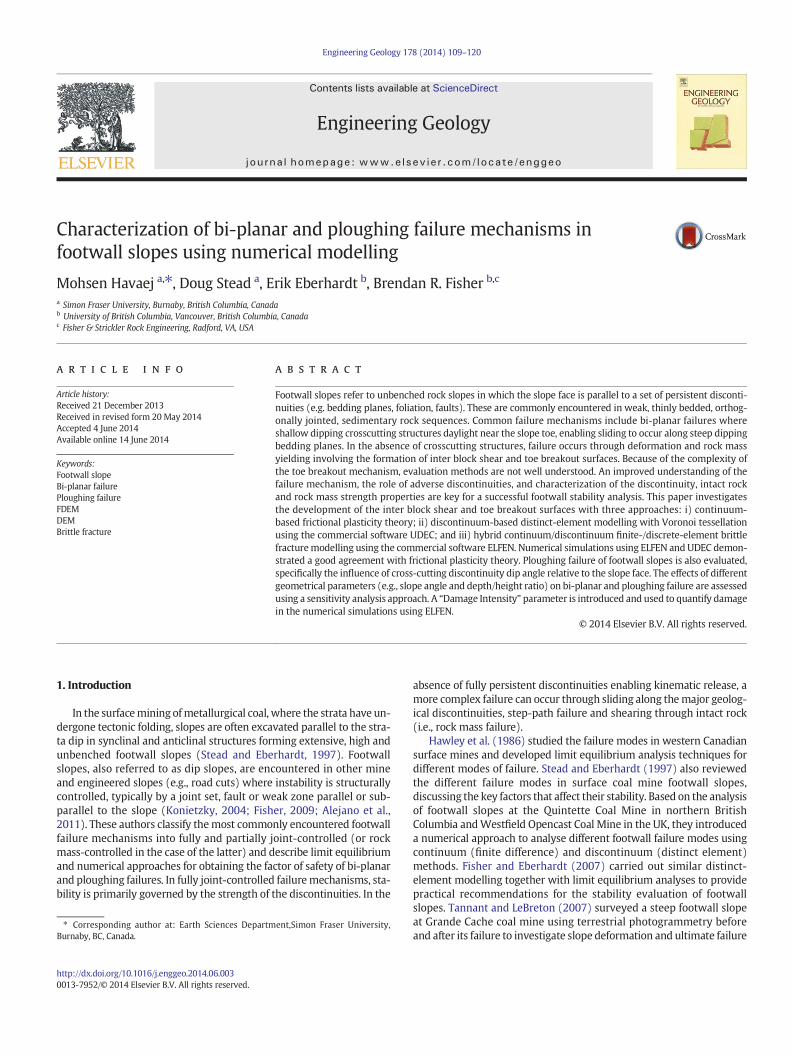
Bi-planar failure occurs when a rock mass slides sub-parallel alongpersistent discontinuities, such as a bedding plane or fault, withkinematic release enabled through shearing along a secondary shallowdipping discontinuity dipping out of the slope face (Figure 1). A reviewof the geotechnical literature suggests that bi-planar footwall slope fail-ures aremost prevalent in weaker, bedded sedimentary rock sequences(e.g., flysch). Footwall slopes are often associated with anticlines,synclines, and homoclines. Although less common, footwall slopesmay also formwhere faults, shears, or lithologic boundaries occur paral-lel to an excavated slope. A good example is that presented by Behrensda Franca (1997). He completed a detailed back analysis of a mine slopethat was excavated exposing a soft hematite layer with a deposit ofitabirite located approximately 30 m behind and parallel to the slopeface. At the contact of the hematite and itabirite, there was a thin layerof soft itabirite or leached iron formation which acted as the slopeparallel sliding surface causing failure. Bi-planar failures have been
Fig. 1. Bi-planar failure of footwall slopes.
reported for natural slopes (e.g. Chen, 1992; Eberhardt et al., 2005).These can develop due to weathering of weaker shale beds or other fac-tors that contribute to progressive failure.
2.1. Different modes of bi-planar failure
Stead and Eberhardt (1997) illustrated variations of bi-planar failuremechanismbased on a survey of UK footwall failures and a reviewof therelevant literature:
2.1.1. Sliding on bedding planes and a basal surface with active/passivezones
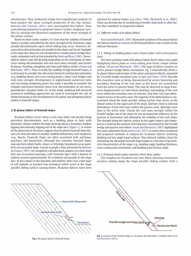
Themost commonmode of bi-planar failure formswhen a low angledaylighting thrust plane or cross-cutting joint forms a basal releasesurface (Stead and Eberhardt, 1997). This type of failure involves anactive–passive wedge failure mechanism. Fig. 2 schematically shows abi-planar failure and location of the active and passive blocks, separatedby a Prandtl wedge transition zone. Kvapil and Clews (1979) describethis transition zone as being characterized by severe fracturing andsecondary shearing of the rock mass as the forces are transmittedfrom the active to passive block. This may be observed as large trans-verse displacements (or inter block shearing) and bulging of the rockmass within the transition zone. In contrast, very little rockmass defor-mation occurs in the active zone. Themajority of thedeformation is con-centrated along the slope-parallel sliding surface that serves as therelease surface in the upper part of the slope. Likewise, there is minimaldisturbance of the rock mass within the passive zone, although morethan in the active zone. Clearly the rock mass strength within thePrandtl wedge and at the slope toe has an important influence on theamount of movement and ultimately the stability of the rock slope.The strength along the rupture surface in the upper slope is also impor-tant as it controls the amount of driving force transmitted to the Prandtlwedge and passive zone below. Stead and Eberhardt (1997) highlightedthework undertaken by Brawner et al. (1971) inwhich they recognizedand proposed methods of analysis for bi-planar failures involvingbedding and low angle basal surfaces. They derived stability charts forestimating the allowable footwall slope height as a function of geomet-rical characteristics of the slope; e.g., bedding angle, bedding thickness,cross-cutting joint orientation, and bedding/joint friction angle.
2.1.2. Persistent basal surface and inter block shear surfaceThe simplest toe breakout and inter block shearing mechanism
involves sliding along the slope parallel sliding surface with a
Fig. 2. Location of the Prandtl wedge in a bi-planar footwall failure (modified after Steadand Eberhardt (1997)).

Fig. 3. Parameters used in the frictional plasticity approach.
111M. Havaej et al. / Engineering Geology 178 (2014) 109–120
persistent joint dipping out of the slope and a joint (or other persis-tent discontinuity) dipping steeply into the slope separating the active/passive wedges and providing kinematic release of the slope (Nathanail,1996). The slope and structural geology model required for this type offailure is shown in Fig. 1 where it could be envisioned that the interblock shear and toe breakout surfaces both consist of through-goingdiscontinuities. This model illustrates that in addition to the basal shearsurface, inter block shear is required for slope release.
2.1.3. Step-path failuresA step-path (or rock mass) failure occurs where toe break out and/or
inter block shear develops through the combined sliding along non-persistent joints and failure of intact rock bridges. Jennings (1970) pre-sented a detailed limit equilibrium model for estimating the stability ofa slope where step-path failure may occur. The model effectively uses aweighted average of the shear strength of the joints and the shearstrength (or tensile strength) of the intact rock throughwhich the slidingsurface develops. More recently, the Hoek–Brown failure criterion pre-sents a means to weight the combined influence of intact rock and non-persistent joint strength as an equivalent continuum rock mass strength(Hoek and Brown, 1997; Hoek et al., 2002; Carvalho et al., 2007). Giani
Fig. 4. Bi-planar failure in
(1992) provides a detailed account of a footwall slope back analysiswhere the toe breakout was modelled using the Hoek–Brown failure cri-terion. It should be noted, though, that the treatment of the step-pathproblem as an equivalent continuum neglects the important kinematicand directional controls that exist where the discontinuities are of mod-erate persistence. In such cases, the equivalent continuum approachmay only apply to the rock mass strength of the rock bridges to accountfor smaller-scale discontinuities that serve to weaken the rock bridge.
2.1.4. Buckling modelA footwall buckling failure is characterized by bending and sliding
(flexural slip) of the outermost layers above the toe of the slope as atoe breakout surface or inter block shear develops. Buckling prior tokinematic release in layered sedimentary rock has been reportedalong the Yalong River, China (Wang et al., 1992), Yangtze River,China (Li et al., 1992) and within several coal mines in Canada and theUK (e.g., Scoble, 1981; Cruden and Masoumzadeh, 1987; Stead andEberhardt, 1997). Jin et al. (1992) and Li et al. (1992) both providedetails of a friction model analysis of these bi-planar slope failureswhich occurred over a 50-month period. The model was constructedto represent bedded strata in which bedding was inclined at an angle
sedimentary rock.
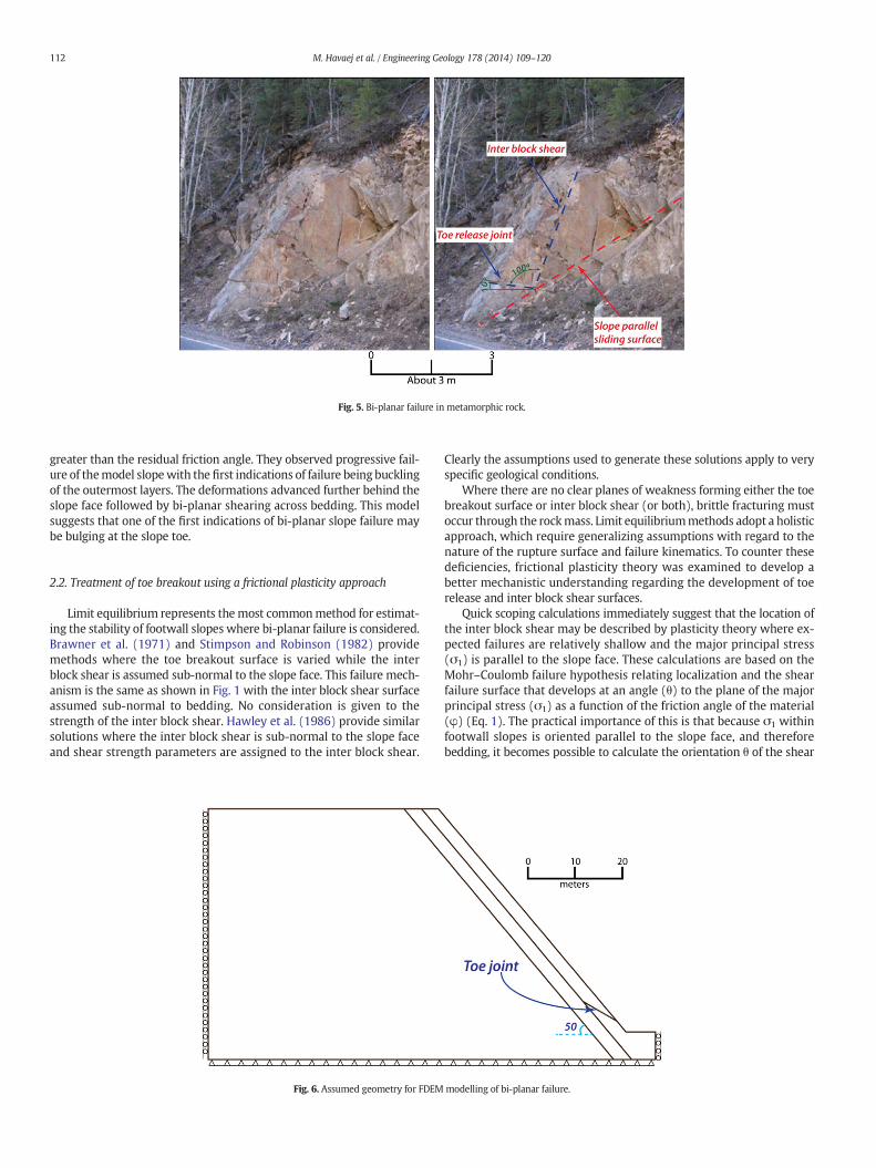
Fig. 5. Bi-planar failure in metamorphic rock.
112 M. Havaej et al. / Engineering Geology 178 (2014) 109–120
greater than the residual friction angle. They observed progressive fail-ure of themodel slopewith the first indications of failure being bucklingof the outermost layers. The deformations advanced further behind theslope face followed by bi-planar shearing across bedding. This modelsuggests that one of the first indications of bi-planar slope failure maybe bulging at the slope toe.
2.2. Treatment of toe breakout using a frictional plasticity approach
Limit equilibrium represents themost commonmethod for estimat-ing the stability of footwall slopes where bi-planar failure is considered.Brawner et al. (1971) and Stimpson and Robinson (1982) providemethods where the toe breakout surface is varied while the interblock shear is assumed sub-normal to the slope face. This failure mech-anism is the same as shown in Fig. 1 with the inter block shear surfaceassumed sub-normal to bedding. No consideration is given to thestrength of the inter block shear. Hawley et al. (1986) provide similarsolutions where the inter block shear is sub-normal to the slope faceand shear strength parameters are assigned to the inter block shear.
Fig. 6. Assumed geometry for FDEM
Clearly the assumptions used to generate these solutions apply to veryspecific geological conditions.
Where there are no clear planes of weakness forming either the toebreakout surface or inter block shear (or both), brittle fracturing mustoccur through the rockmass. Limit equilibriummethods adopt a holisticapproach, which require generalizing assumptions with regard to thenature of the rupture surface and failure kinematics. To counter thesedeficiencies, frictional plasticity theory was examined to develop abetter mechanistic understanding regarding the development of toerelease and inter block shear surfaces.
Quick scoping calculations immediately suggest that the location ofthe inter block shear may be described by plasticity theory where ex-pected failures are relatively shallow and the major principal stress(σ1) is parallel to the slope face. These calculations are based on theMohr–Coulomb failure hypothesis relating localization and the shearfailure surface that develops at an angle (θ) to the plane of the majorprincipal stress (σ1) as a function of the friction angle of the material(φ) (Eq. 1). The practical importance of this is that because σ1 withinfootwall slopes is oriented parallel to the slope face, and thereforebedding, it becomes possible to calculate the orientation θ of the shear
modelling of bi-planar failure.
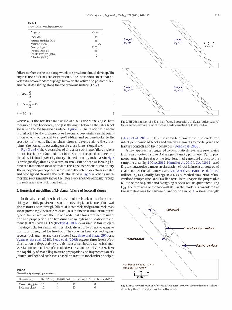
Table 1Intact rock strength parameters.
Property Value
USC (MPa) 30Young's modulus (GPa) 15Poisson's Ratio 0.25Density (kg/m3) 2500Friction angle (°) 45Tensile strength (MPa) 2Cohesion (MPa) 5
Fig. 7. ELFEN simulation of a 50 m high footwall slope with a bi-planar (active–passive)failure surface showing stages of fracture development leading to slope failure.
113M. Havaej et al. / Engineering Geology 178 (2014) 109–120
failure surface at the toe along which toe breakout should develop. Theangle θ also describes the orientation of the inter block shear that de-velops to accommodate slippage between the active and passive blocksand facilitates sliding along the toe breakout surface (Eq. 2).
θ ¼ 45−φ2
1
ψ ¼ αþ φ2−45 2
β ¼ 90þ θ 3
where ψ is the toe breakout angle and α is the slope angle, bothmeasured from horizontal, and β is the angle between the inter blockshear and the toe breakout surface (Figure 3). The relationship aboveis unaffected by the presence of orthogonal cross-jointing as the orien-tation of σ1 (i.e., parallel to slope/bedding and perpendicular to thecross joints) means that no shear stresses develop along the cross-joints; the normal stress acting on the cross joints is equal to σ1.
Figs. 3 and 4 show examples of bi-planar rock slope failures wherethe toe breakout surface and inter block shear correspond to those pre-dicted by frictional plasticity theory. The sedimentary rockmass in Fig. 4is orthogonally jointed and a tension crack can be seen as forming be-hind the inter block shear normal to the slope coincident discontinuity.The orthogonal joint opened in tension as the inter block shear initiatedand propagated through the rock. The slope in Fig. 5 involving meta-morphic rock similarly shows the inter block shear developing throughthe rock mass as a rock mass failure.
3. Numerical modelling of bi-planar failure of footwall slopes
In the absence of inter block shear and toe break-out surfaces coin-ciding with fully persistent discontinuities, bi-planar failure of footwallslopes must occur through failure of intact rock bridges and rock massshear providing kinematic release. Thus, numerical simulation of thistype of failure requires the use of a code that allows for fracture initia-tion and propagation. The two dimensional hybrid finite/discrete ele-ment (FDEM) code ELFEN (Rockfield., 2009) was used in this study toinvestigate the formation of inter block shear surfaces, active–passivetransition zones, and toe breakout. The code has been verified againstseveral rock engineering case studies (e.g., Elmo and Stead, 2010 andVyazmensky et al., 2010). Stead et al. (2006) suggest three levels of so-phistication in slope stability problems in which hybrid numerical anal-yses fall in the third level of complexity. FDEM codes such as ELFENhavethe capability of modelling fracture propagation and fragmentation of ajointed and bedded rock mass based on fracture mechanics principles
Table 2Discontinuity strength parameters.
Discontinuity Kn (GPa/m) Ks (GPa/m) Friction angle (°) Cohesion (MPa)
Crosscutting joint 10 1 40 0Beddings plane 10 1 30 0
(Stead et al., 2006). ELFEN uses a finite element mesh to model theintact joint bounded blocks and discrete elements to model joint andfracture contacts and their behaviour (Stead et al., 2006).
A new approach is suggested to quantitatively evaluate progressivefailure in a footwall slope. A damage intensity parameter D21 is pro-posed equal to the ratio of the total length of generated cracks to thesampling area, Eq. 4 (Gao, 2013; Hamdi et al., 2013). Gao (2013) usedD21 to characterize damage in simulation of roof failure in undergroundcoal mines. At the laboratory scale, Gao (2013) and Hamdi et al. (2013)utilized D21 to quantify damage in 2D/3D numerical simulation of un-confined compression and Brazilian tests. In this paper, the progressivefailure of the bi-planar and ploughing models will be quantified usingD21. The total area of the footwall slab in the models is considered asthe sampling area for damage quantification in Eq. 4. A shear strength
Fig. 8. Inset showing location of the transition zone (between the two fracture surfaces),delimiting the active and passive block, D21 = 2.8.
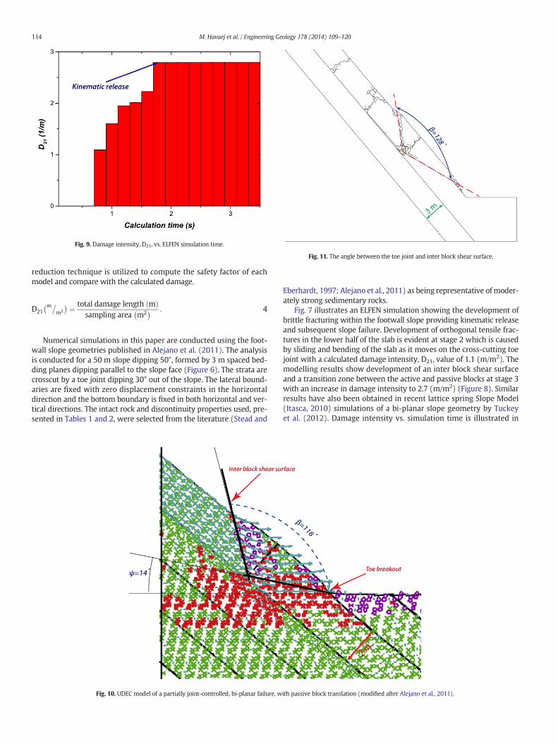
Fig. 9. Damage intensity, D21, vs. ELFEN simulation time.
Fig. 11. The angle between the toe joint and inter block shear surface.
114 M. Havaej et al. / Engineering Geology 178 (2014) 109–120
reduction technique is utilized to compute the safety factor of eachmodel and compare with the calculated damage.
D21m�
m2
� � ¼ total damage length mð Þsampling area m2
� � : 4
Numerical simulations in this paper are conducted using the foot-wall slope geometries published in Alejano et al. (2011). The analysisis conducted for a 50 m slope dipping 50°, formed by 3 m spaced bed-ding planes dipping parallel to the slope face (Figure 6). The strata arecrosscut by a toe joint dipping 30° out of the slope. The lateral bound-aries are fixed with zero displacement constraints in the horizontaldirection and the bottom boundary is fixed in both horizontal and ver-tical directions. The intact rock and discontinuity properties used, pre-sented in Tables 1 and 2, were selected from the literature (Stead and
Fig. 10. UDEC model of a partially joint-controlled, bi-planar failure, w
Eberhardt, 1997; Alejano et al., 2011) as being representative of moder-ately strong sedimentary rocks.
Fig. 7 illustrates an ELFEN simulation showing the development ofbrittle fracturing within the footwall slope providing kinematic releaseand subsequent slope failure. Development of orthogonal tensile frac-tures in the lower half of the slab is evident at stage 2 which is causedby sliding and bending of the slab as it moves on the cross-cutting toejoint with a calculated damage intensity, D21, value of 1.1 (m/m2). Themodelling results show development of an inter block shear surfaceand a transition zone between the active and passive blocks at stage 3with an increase in damage intensity to 2.7 (m/m2) (Figure 8). Similarresults have also been obtained in recent lattice spring Slope Model(Itasca, 2010) simulations of a bi-planar slope geometry by Tuckeyet al. (2012). Damage intensity vs. simulation time is illustrated in
ith passive block translation (modified after Alejano et al., 2011).
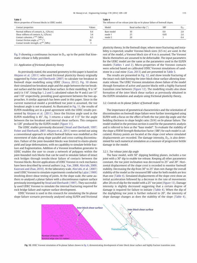
Table 3Micro-properties of Voronoi blocks in UDEC model.
Contact properties Values
Normal stiffness of contacts, kn (GPa/m) 8.4Shear stiffness of contacts, ks (GPa/m) 3.4Contact cohesion, ccont (MPa) 6.5Contact friction angle, φcont (°) 18Contact tensile strength, σt
cont (MPa) 3
Table 4The influence of toe release joint dip on bi-planar failure of footwall slopes.
Model Basal surface dip (°) SRF D21
Base model 30 0.8 2.8mode 1 25 0.85 2.6mode 2 20 1 0.4
115M. Havaej et al. / Engineering Geology 178 (2014) 109–120
Fig. 9 showing a continuous increase in D21 up to the point that kine-matic release is fully provided.
3.1. Application of frictional plasticity theory
As previously stated, the assumed geometry in this paper is based onAlejano et al. (2011) who used frictional plasticity theory originallysuggested by Fisher and Eberhardt (2007) to calculate toe breakout infootwall slope modelling using UDEC (Itasca, 2012). Fig. 10 showstheir simulated toe breakout angle and the angle between the toe break-out surface and the inter block shear surface. In their modelling,Ψ is 14°and β is 116°. Using Eqs 1, 2 and 3, calculated values forΨ and β are 13°and 118° respectively, providing good agreement between the two ap-proaches. A similar approach has been used in this paper. Since in thecurrent numerical model a predefined toe joint is assumed, the toebreakout angle is not evaluated. As illustrated in Fig. 11, the results ofELFEN modelling are in a good agreement with the UDEC results pre-sented by Alejano et al. (2011). Since the friction angle used in theELFEN modelling is 45°, Eq. 3 returns a value of 113° for the anglebetween the toe breakout and internal shear surfaces. This comparesto 128° produced by the ELFEN model (Figure 11).
The UDEC studies previously discussed (Stead and Eberhardt, 1997;Fisher and Eberhardt, 2007; Alejano et al., 2011) were carried out usinga conventional approach in which footwall failure was modelled as themovement of slabs along slope parallel and cross-cutting discontinu-ities. Failure of the joint-bounded blocks was limited to elasto-plasticyield and large deformations, with no capability to simulate brittle frac-ture and fragmentation. Addition of a Voronoi tessellation generator toUDEC enables the user to create a network of polygons within thejoint-bounded rock blocks that can be used to simulate failure of intactrock bridges through tensile/shear failure of contacts between theVoronoi blocks. Recent applications of UDEC Voronoi in rockmechanicshave been described by several authors (e.g., Yan, 2008; Alzo'ubi, 2009;Kazerani and Zhao, 2010). At the laboratory scale, Alzo'ubi, et al. (2007)used UDECVoronoi to simulate experiments conducted by Lajtai (1969)involving direct shear testing of joints. At the slope scale, the same au-thors re-analysed a planar failure with a discontinuous rupture surfacepreviously investigated by Stead and Eberhardt (1997). They successful-ly used UDEC Voronoi to simulate the internal fracturing required forrock bridge failure and rupture surface development.
UDEC Voronoi is used in this research for simulating the bi-planarslope failure scenario previously analysed using ELFEN and frictional
Fig. 12. UDEC Voronoi simulation of bi-planar failure shown in fig. 6, demonstrating
plasticity theory. In the footwall slope, wheremore fracturing and insta-bility is expected, smaller Voronoi block sizes (0.5 m) are used. In therest of the model, a Voronoi block size of 4 m is assumed. The Voronoiblocks themselves are assumed to be deformable. The input parametersfor the UDEC model are the same as the parameters used in the ELFENmodels (Tables 1 and 2). Micro-properties of the Voronoi contactswere selected based on calibrated UDEC Voronoi simulations of sand-stone in a coal mine (Gao, 2013) and are presented in Table 3.
The results are presented in Fig. 12, and show tensile fracturing ofthe intact rock slab forming the inter block shear surface allowing kine-matic release. The UDEC Voronoi simulation shows failure of the modelthrough formation of active and passive blocks with a highly fracturedtransition zone between (Figure 12). The modelling results also showformation of the inter block shear surface as previously obtained inthe ELFEN simulation and analysis using frictional plasticity theory.
3.2. Controls on bi-planar failure of footwall slopes
The importance of geometrical characteristics and the orientation ofdiscontinuities on footwall slope failure were further investigated usingELFEN with a focus on the effect of both the toe joint dip angle and thebedding thickness to slope height ratio (D/H) on bi-planar failure. Themodel studied in the previous section is used for the parametric analysisand is referred to here as the “base model”. To evaluate the stability ofthe slope a FDEM Strength Reduction Factor (SRF) for eachmodel is cal-culated. History points are located at the slope crest where simulateddisplacements are recorded. The damage intensity, D21 is also deter-mined for each numerical simulation as ameasure of progressive brittledamage in the model.
3.2.1. Toe release joint dip angleThe base model, with 50° dipping bedding planes, includes a toe
joint with a 30° dip to enable toe release. Keeping all other parametersconstant, the toe joint inclination was decreased to 25° and 20°. Hori-zontal displacement of the slope crest is recorded to monitor footwallstability. Decreasing the dip from 30° to 25° does not change the overallstability of themodel as themeasured SRF value for bothmodels are lessthan one (Table 4). Simulated displacements of the slope crest show aninitial acceleration followed by a decrease in the rate of movementsafter 20 cmof slip for themodelwith a 25° toe joint (Figure 13). Damageintensity is slightly decreased suggesting that a certain degree ofdamage is required for failure to initiate (Table 4). When the dip ofthe daylighting toe joint is further reduced to 20°, the intensity ofslope damage changes as does the stability of the slope (Table 4).
development of inter block shear surface and highly fracture transition zone.
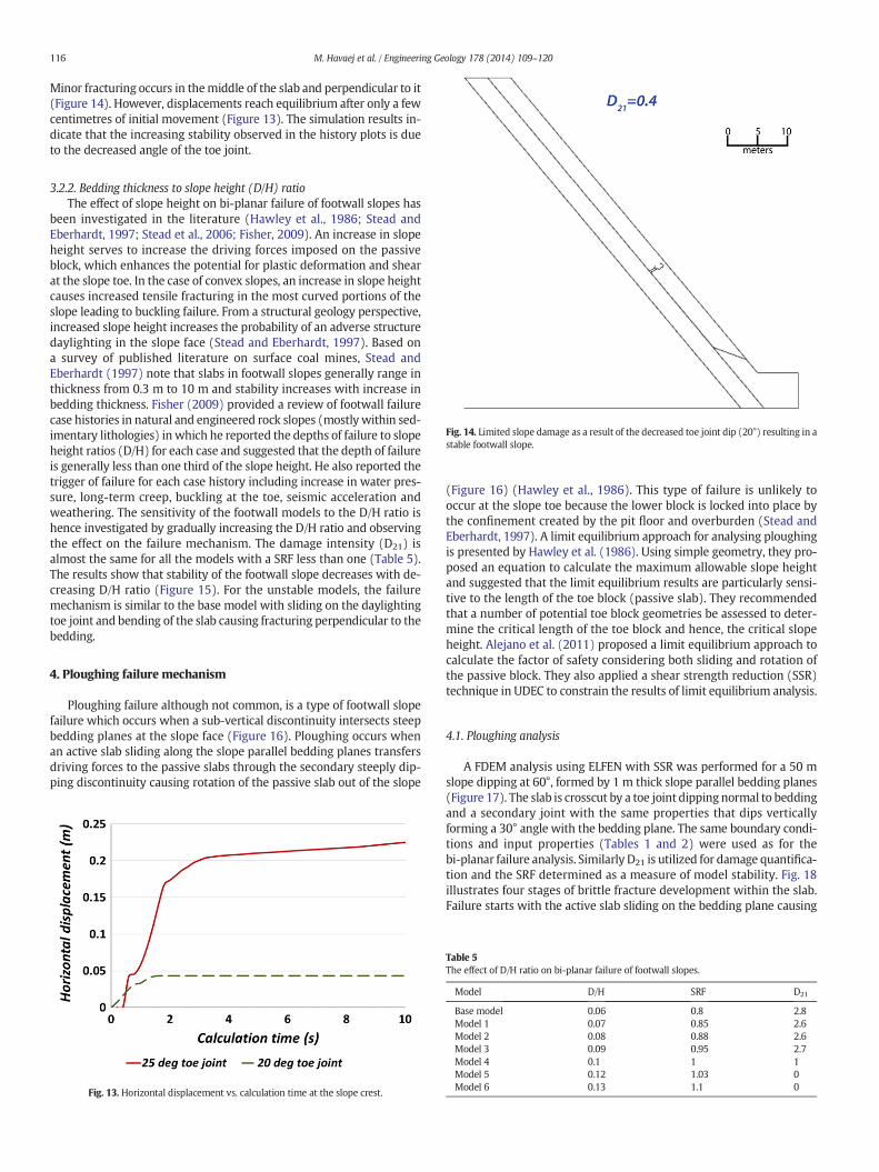
Fig. 14. Limited slope damage as a result of the decreased toe joint dip (20°) resulting in astable footwall slope.
116 M. Havaej et al. / Engineering Geology 178 (2014) 109–120
Minor fracturing occurs in themiddle of the slab and perpendicular to it(Figure 14). However, displacements reach equilibrium after only a fewcentimetres of initial movement (Figure 13). The simulation results in-dicate that the increasing stability observed in the history plots is dueto the decreased angle of the toe joint.
3.2.2. Bedding thickness to slope height (D/H) ratioThe effect of slope height on bi-planar failure of footwall slopes has
been investigated in the literature (Hawley et al., 1986; Stead andEberhardt, 1997; Stead et al., 2006; Fisher, 2009). An increase in slopeheight serves to increase the driving forces imposed on the passiveblock, which enhances the potential for plastic deformation and shearat the slope toe. In the case of convex slopes, an increase in slope heightcauses increased tensile fracturing in the most curved portions of theslope leading to buckling failure. From a structural geology perspective,increased slope height increases the probability of an adverse structuredaylighting in the slope face (Stead and Eberhardt, 1997). Based ona survey of published literature on surface coal mines, Stead andEberhardt (1997) note that slabs in footwall slopes generally range inthickness from 0.3 m to 10 m and stability increases with increase inbedding thickness. Fisher (2009) provided a review of footwall failurecase histories in natural and engineered rock slopes (mostly within sed-imentary lithologies) in which he reported the depths of failure to slopeheight ratios (D/H) for each case and suggested that the depth of failureis generally less than one third of the slope height. He also reported thetrigger of failure for each case history including increase in water pres-sure, long-term creep, buckling at the toe, seismic acceleration andweathering. The sensitivity of the footwall models to the D/H ratio ishence investigated by gradually increasing the D/H ratio and observingthe effect on the failure mechanism. The damage intensity (D21) isalmost the same for all the models with a SRF less than one (Table 5).The results show that stability of the footwall slope decreases with de-creasing D/H ratio (Figure 15). For the unstable models, the failuremechanism is similar to the base model with sliding on the daylightingtoe joint and bending of the slab causing fracturing perpendicular to thebedding.
4. Ploughing failure mechanism
Ploughing failure although not common, is a type of footwall slopefailure which occurs when a sub-vertical discontinuity intersects steepbedding planes at the slope face (Figure 16). Ploughing occurs whenan active slab sliding along the slope parallel bedding planes transfersdriving forces to the passive slabs through the secondary steeply dip-ping discontinuity causing rotation of the passive slab out of the slope
Fig. 13. Horizontal displacement vs. calculation time at the slope crest.
(Figure 16) (Hawley et al., 1986). This type of failure is unlikely tooccur at the slope toe because the lower block is locked into place bythe confinement created by the pit floor and overburden (Stead andEberhardt, 1997). A limit equilibrium approach for analysing ploughingis presented by Hawley et al. (1986). Using simple geometry, they pro-posed an equation to calculate the maximum allowable slope heightand suggested that the limit equilibrium results are particularly sensi-tive to the length of the toe block (passive slab). They recommendedthat a number of potential toe block geometries be assessed to deter-mine the critical length of the toe block and hence, the critical slopeheight. Alejano et al. (2011) proposed a limit equilibrium approach tocalculate the factor of safety considering both sliding and rotation ofthe passive block. They also applied a shear strength reduction (SSR)technique in UDEC to constrain the results of limit equilibrium analysis.
4.1. Ploughing analysis
A FDEM analysis using ELFEN with SSR was performed for a 50 mslope dipping at 60°, formed by 1 m thick slope parallel bedding planes(Figure 17). The slab is crosscut by a toe joint dipping normal to beddingand a secondary joint with the same properties that dips verticallyforming a 30° angle with the bedding plane. The same boundary condi-tions and input properties (Tables 1 and 2) were used as for thebi-planar failure analysis. Similarly D21 is utilized for damage quantifica-tion and the SRF determined as a measure of model stability. Fig. 18illustrates four stages of brittle fracture development within the slab.Failure starts with the active slab sliding on the bedding plane causing
Table 5The effect of D/H ratio on bi-planar failure of footwall slopes.
Model D/H SRF D21
Base model 0.06 0.8 2.8Model 1 0.07 0.85 2.6Model 2 0.08 0.88 2.6Model 3 0.09 0.95 2.7Model 4 0.1 1 1Model 5 0.12 1.03 0Model 6 0.13 1.1 0
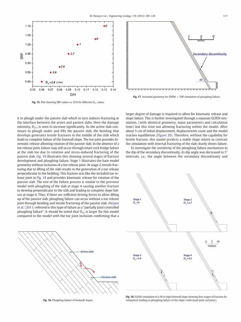
Fig. 17. Assumed geometry for FDEM + SSR simulation of ploughing failure.
Fig. 15. Plot showing SRF values vs. D/H for different D21 ratios.
117M. Havaej et al. / Engineering Geology 178 (2014) 109–120
it to plough under the passive slab which in turn induces fracturing atthe interface between the active and passive slabs. Here the damageintensity, D21, is seen to increase significantly. As the active slab con-tinues to plough under and lifts the passive slab, the bending thatdevelops generates tensile fractures in the middle of the slab whichleads to complete failure of the footwall slope. The toe joint provides ki-nematic release allowing rotation of the passive slab. In the absence of atoe release joint, failuremay still occur through intact rock bridge failureat the slab toe due to rotation and stress-induced fracturing of thepassive slab. Fig. 19 illustrates this showing several stages of fracturedevelopment and ploughing failure. Stage 1 illustrates the base modelgeometrywithout inclusion of a toe release joint. At stage 2, tensile frac-turing due to lifting of the slab results in the generation of a toe releaseperpendicular to the bedding. This fracture acts like the included toe re-lease joint in Fig. 18 and provides kinematic release for rotation of thepassive slab. The rest of the failure process is similar to the previousmodel with ploughing of the slab at stage 4 causing another fractureto develop perpendicular to the slab and leading to complete slope fail-ure at stage 6. Thus, if there are sufficient driving forces to allow liftingup of the passive slab, ploughing failure can occur without a toe releasejoint through bending and tensile fracturing of the passive slab. Alejanoet al. (2011) referred to this type of failure as a “partially joint controlledploughing failure”. It should be noted that D21 is larger for this modelcompared to the model with the toe joint inclusion confirming that a
Fig. 16. Ploughing failure of footwall slopes.
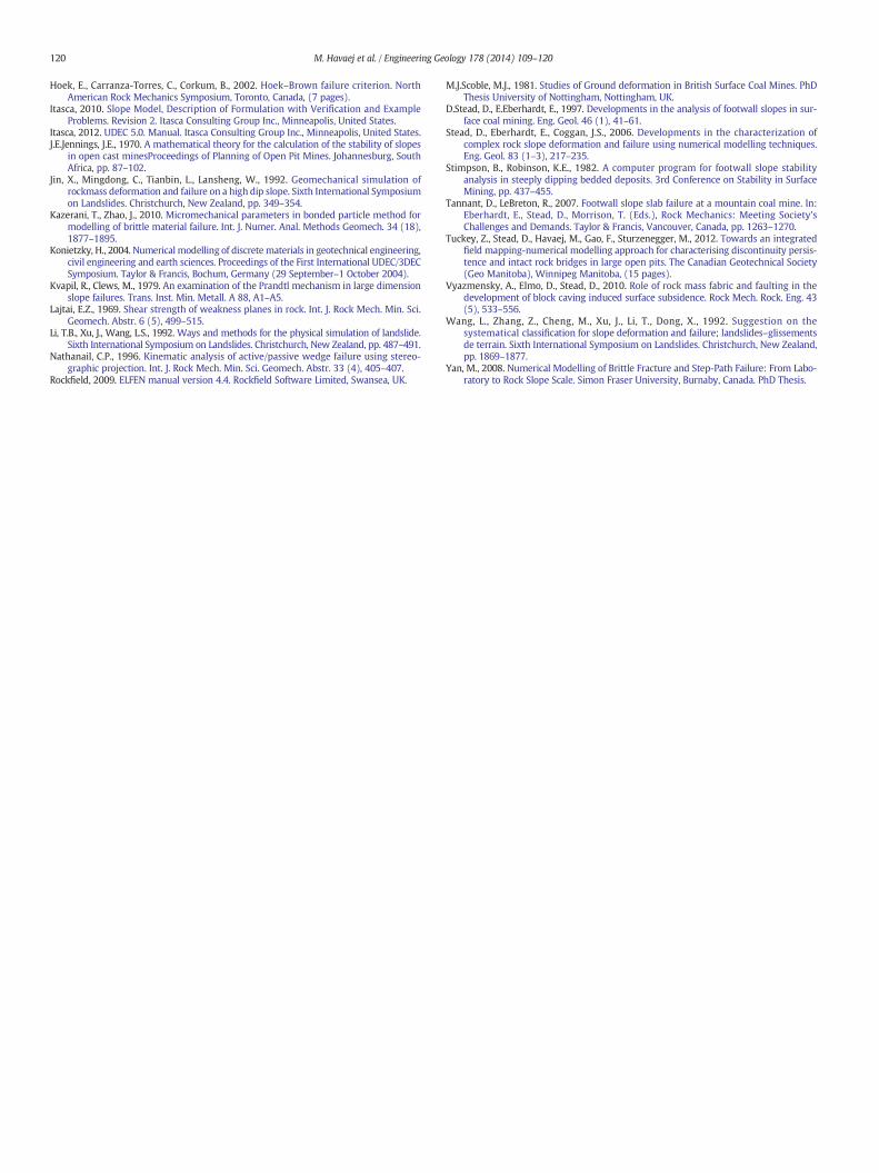
larger degree of damage is required to allow for kinematic release andslope failure. This is further investigated through a separate ELFEN sim-ulation, (with identical geometry, input parameters and calculationtime) but this time not allowing fracturing within the model. Afterabout 5 cm of initial displacement, displacements cease and the modelreaches equilibrium (Figure 20). Therefore, without the capability forbrittle fracture, this model predicts a stable slope where in contrastthe simulation with internal fracturing of the slab clearly shows failure.
To investigate the sensitivity of the ploughing failure mechanism tothe dip of the secondary discontinuity, its dip angle was decreased in 5°intervals. i.e., the angle between the secondary discontinuity and
Fig. 18. ELFEN simulation of a 50m high footwall slope showing four stages of fracture de-velopment leading to ploughing failure of the slope (with basal joint inclusion).
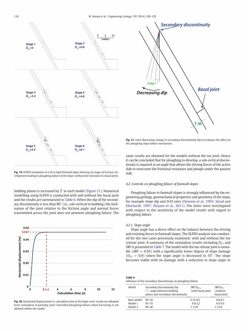
Fig. 19. ELFEN simulation of a 56 m high footwall slope showing six stages of fracture de-velopment leading to ploughing failure of the slope (without the inclusion of a basal joint).
Fig. 21. Inset illustrating change in secondary discontinuity dip to evaluate the effect onthe ploughing slope failure mechanism.
118 M. Havaej et al. / Engineering Geology 178 (2014) 109–120
bedding planes is increased by 5° in each model (Figure 21). Numericalmodelling using ELFEN is conducted with and without the basal jointand the results are summarized in Table 6. When the dip of the second-ary discontinuity is less than 80° (i.e., sub-vertical to bedding) the incli-nation of the joint relative to the friction angle and normal forcestransmitted across the joint does not promote ploughing failure. The
Fig. 20.Horizontal displacement vs. calculation time at the slope crest; results are obtainedfrom simulation of partially joint controlled ploughing failure when fracturing is notallowed within the model.
same results are obtained for the models without the toe joint. Henceit can be concluded that for ploughing to develop, a sub-vertical discon-tinuity is required at an angle that allows the driving forces of the activeslab to overcome the frictional resistance and plough under the passiveslab.
4.2. Controls on ploughing failure of footwall slopes
Ploughing failure in footwall slopes is strongly influenced by the en-gineering geology, geomechanical properties and geometry of the slope,for example slope dip and D/H ratio (Dawson et al., 1993; Stead andEberhardt, 1997; Alejano et al., 2011). The latter were investigatedwith respect to the sensitivity of the model results with regard toploughing failure.
4.2.1. Slope angleSlope angle has a direct effect on the balance between the driving
and resisting forces in footwall slopes. The ELFEN analysis was conduct-ed for the two cases previously examined: with and without the toerelease joint. A summary of the simulation results including D21 andSRF is presented in Table 7. Themodelwith the toe release joint is unsta-ble (SRF = 0.95) with a significantly lower degree of slope damage(D21 = 0.9) when the slope angle is decreased to 55°. The slopebecomes stable with no damage with a reduction in slope angle to
Table 6Influence of the secondary discontinuity on ploughing failure.
Model Secondary discontinuity dip(°) -angle between beddingplanes and secondary discontinuity
SRF/D21a
(with basal joint)SRF/D21
(withoutbasal joint)
Base model 90–30 0.75/4.2 0.8/6.1Model 1 85–35 0.9/2.2 0.9/5.6Model 2 80–40 1.13/0 1.15/0
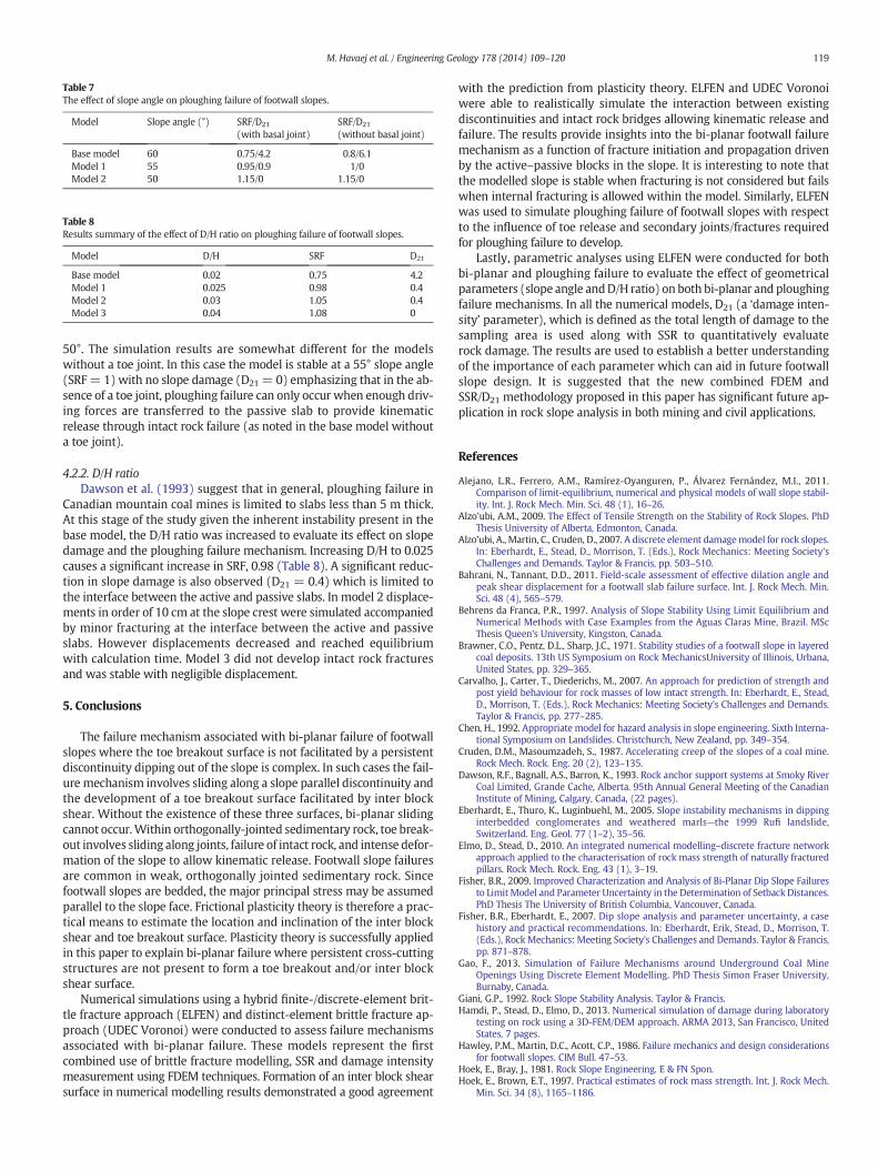
Table 7The effect of slope angle on ploughing failure of footwall slopes.
Model Slope angle (°) SRF/D21
(with basal joint)SRF/D21
(without basal joint)
Base model 60 0.75/4.2 0.8/6.1Model 1 55 0.95/0.9 1/0Model 2 50 1.15/0 1.15/0
Table 8Results summary of the effect of D/H ratio on ploughing failure of footwall slopes.
Model D/H SRF D21
Base model 0.02 0.75 4.2Model 1 0.025 0.98 0.4Model 2 0.03 1.05 0.4Model 3 0.04 1.08 0
119M. Havaej et al. / Engineering Geology 178 (2014) 109–120
50°. The simulation results are somewhat different for the modelswithout a toe joint. In this case the model is stable at a 55° slope angle(SRF= 1) with no slope damage (D21 = 0) emphasizing that in the ab-sence of a toe joint, ploughing failure can only occur when enough driv-ing forces are transferred to the passive slab to provide kinematicrelease through intact rock failure (as noted in the base model withouta toe joint).
4.2.2. D/H ratioDawson et al. (1993) suggest that in general, ploughing failure in
Canadian mountain coal mines is limited to slabs less than 5 m thick.At this stage of the study given the inherent instability present in thebase model, the D/H ratio was increased to evaluate its effect on slopedamage and the ploughing failure mechanism. Increasing D/H to 0.025causes a significant increase in SRF, 0.98 (Table 8). A significant reduc-tion in slope damage is also observed (D21 = 0.4) which is limited tothe interface between the active and passive slabs. In model 2 displace-ments in order of 10 cm at the slope crest were simulated accompaniedby minor fracturing at the interface between the active and passiveslabs. However displacements decreased and reached equilibriumwith calculation time. Model 3 did not develop intact rock fracturesand was stable with negligible displacement.
5. Conclusions
The failure mechanism associated with bi-planar failure of footwallslopes where the toe breakout surface is not facilitated by a persistentdiscontinuity dipping out of the slope is complex. In such cases the fail-ure mechanism involves sliding along a slope parallel discontinuity andthe development of a toe breakout surface facilitated by inter blockshear. Without the existence of these three surfaces, bi-planar slidingcannot occur.Within orthogonally-jointed sedimentary rock, toe break-out involves sliding along joints, failure of intact rock, and intense defor-mation of the slope to allow kinematic release. Footwall slope failuresare common in weak, orthogonally jointed sedimentary rock. Sincefootwall slopes are bedded, the major principal stress may be assumedparallel to the slope face. Frictional plasticity theory is therefore a prac-tical means to estimate the location and inclination of the inter blockshear and toe breakout surface. Plasticity theory is successfully appliedin this paper to explain bi-planar failure where persistent cross-cuttingstructures are not present to form a toe breakout and/or inter blockshear surface.
Numerical simulations using a hybrid finite-/discrete-element brit-tle fracture approach (ELFEN) and distinct-element brittle fracture ap-proach (UDEC Voronoi) were conducted to assess failure mechanismsassociated with bi-planar failure. These models represent the firstcombined use of brittle fracture modelling, SSR and damage intensitymeasurement using FDEM techniques. Formation of an inter block shearsurface in numerical modelling results demonstrated a good agreement
with the prediction from plasticity theory. ELFEN and UDEC Voronoiwere able to realistically simulate the interaction between existingdiscontinuities and intact rock bridges allowing kinematic release andfailure. The results provide insights into the bi-planar footwall failuremechanism as a function of fracture initiation and propagation drivenby the active–passive blocks in the slope. It is interesting to note thatthe modelled slope is stable when fracturing is not considered but failswhen internal fracturing is allowed within the model. Similarly, ELFENwas used to simulate ploughing failure of footwall slopes with respectto the influence of toe release and secondary joints/fractures requiredfor ploughing failure to develop.
Lastly, parametric analyses using ELFEN were conducted for bothbi-planar and ploughing failure to evaluate the effect of geometricalparameters (slope angle andD/H ratio) on both bi-planar and ploughingfailure mechanisms. In all the numerical models, D21 (a ‘damage inten-sity’ parameter), which is defined as the total length of damage to thesampling area is used along with SSR to quantitatively evaluaterock damage. The results are used to establish a better understandingof the importance of each parameter which can aid in future footwallslope design. It is suggested that the new combined FDEM andSSR/D21 methodology proposed in this paper has significant future ap-plication in rock slope analysis in both mining and civil applications.
References
Alejano, L.R., Ferrero, A.M., Ramírez-Oyanguren, P., Álvarez Fernández, M.I., 2011.Comparison of limit-equilibrium, numerical and physical models of wall slope stabil-ity. Int. J. Rock Mech. Min. Sci. 48 (1), 16–26.
Alzo'ubi, A.M., 2009. The Effect of Tensile Strength on the Stability of Rock Slopes. PhDThesis University of Alberta, Edmonton, Canada.
Alzo'ubi, A., Martin, C., Cruden, D., 2007. A discrete element damagemodel for rock slopes.In: Eberhardt, E., Stead, D., Morrison, T. (Eds.), Rock Mechanics: Meeting Society'sChallenges and Demands. Taylor & Francis, pp. 503–510.
Bahrani, N., Tannant, D.D., 2011. Field-scale assessment of effective dilation angle andpeak shear displacement for a footwall slab failure surface. Int. J. Rock Mech. Min.Sci. 48 (4), 565–579.
Behrens da Franca, P.R., 1997. Analysis of Slope Stability Using Limit Equilibrium andNumerical Methods with Case Examples from the Aguas Claras Mine, Brazil. MScThesis Queen's University, Kingston, Canada.
Brawner, C.O., Pentz, D.L., Sharp, J.C., 1971. Stability studies of a footwall slope in layeredcoal deposits. 13th US Symposium on Rock MechanicsUniversity of Illinois, Urbana,United States, pp. 329–365.
Carvalho, J., Carter, T., Diederichs, M., 2007. An approach for prediction of strength andpost yield behaviour for rock masses of low intact strength. In: Eberhardt, E., Stead,D., Morrison, T. (Eds.), Rock Mechanics: Meeting Society's Challenges and Demands.Taylor & Francis, pp. 277–285.
Chen, H., 1992. Appropriate model for hazard analysis in slope engineering. Sixth Interna-tional Symposium on Landslides. Christchurch, New Zealand, pp. 349–354.
Cruden, D.M., Masoumzadeh, S., 1987. Accelerating creep of the slopes of a coal mine.Rock Mech. Rock. Eng. 20 (2), 123–135.
Dawson, R.F., Bagnall, A.S., Barron, K., 1993. Rock anchor support systems at Smoky RiverCoal Limited, Grande Cache, Alberta. 95th Annual General Meeting of the CanadianInstitute of Mining, Calgary, Canada, (22 pages).
Eberhardt, E., Thuro, K., Luginbuehl, M., 2005. Slope instability mechanisms in dippinginterbedded conglomerates and weathered marls—the 1999 Rufi landslide,Switzerland. Eng. Geol. 77 (1–2), 35–56.
Elmo, D., Stead, D., 2010. An integrated numerical modelling–discrete fracture networkapproach applied to the characterisation of rock mass strength of naturally fracturedpillars. Rock Mech. Rock. Eng. 43 (1), 3–19.
Fisher, B.R., 2009. Improved Characterization and Analysis of Bi-Planar Dip Slope Failuresto LimitModel and Parameter Uncertainty in the Determination of Setback Distances.PhD Thesis The University of British Columbia, Vancouver, Canada.
Fisher, B.R., Eberhardt, E., 2007. Dip slope analysis and parameter uncertainty, a casehistory and practical recommendations. In: Eberhardt, Erik, Stead, D., Morrison, T.(Eds.), RockMechanics: Meeting Society's Challenges and Demands. Taylor & Francis,pp. 871–878.
Gao, F., 2013. Simulation of Failure Mechanisms around Underground Coal MineOpenings Using Discrete Element Modelling. PhD Thesis Simon Fraser University,Burnaby, Canada.
Giani, G.P., 1992. Rock Slope Stability Analysis. Taylor & Francis.Hamdi, P., Stead, D., Elmo, D., 2013. Numerical simulation of damage during laboratory
testing on rock using a 3D-FEM/DEM approach. ARMA 2013, San Francisco, UnitedStates, 7 pages.
Hawley, P.M., Martin, D.C., Acott, C.P., 1986. Failure mechanics and design considerationsfor footwall slopes. CIM Bull. 47–53.
Hoek, E., Bray, J., 1981. Rock Slope Engineering. E & FN Spon.Hoek, E., Brown, E.T., 1997. Practical estimates of rock mass strength. Int. J. Rock Mech.
Min. Sci. 34 (8), 1165–1186.
120 M. Havaej et al. / Engineering Geology 178 (2014) 109–120
Hoek, E., Carranza-Torres, C., Corkum, B., 2002. Hoek–Brown failure criterion. NorthAmerican Rock Mechanics Symposium, Toronto, Canada, (7 pages).
Itasca, 2010. Slope Model, Description of Formulation with Verification and ExampleProblems. Revision 2. Itasca Consulting Group Inc., Minneapolis, United States.
Itasca, 2012. UDEC 5.0. Manual. Itasca Consulting Group Inc., Minneapolis, United States.J.E.Jennings, J.E., 1970. A mathematical theory for the calculation of the stability of slopes
in open cast minesProceedings of Planning of Open Pit Mines. Johannesburg, SouthAfrica, pp. 87–102.
Jin, X., Mingdong, C., Tianbin, L., Lansheng, W., 1992. Geomechanical simulation ofrockmass deformation and failure on a high dip slope. Sixth International Symposiumon Landslides. Christchurch, New Zealand, pp. 349–354.
Kazerani, T., Zhao, J., 2010. Micromechanical parameters in bonded particle method formodelling of brittle material failure. Int. J. Numer. Anal. Methods Geomech. 34 (18),1877–1895.
Konietzky, H., 2004. Numerical modelling of discrete materials in geotechnical engineering,civil engineering and earth sciences. Proceedings of the First International UDEC/3DECSymposium. Taylor & Francis, Bochum, Germany (29 September–1 October 2004).
Kvapil, R., Clews, M., 1979. An examination of the Prandtl mechanism in large dimensionslope failures. Trans. Inst. Min. Metall. A 88, A1–A5.
Lajtai, E.Z., 1969. Shear strength of weakness planes in rock. Int. J. Rock Mech. Min. Sci.Geomech. Abstr. 6 (5), 499–515.
Li, T.B., Xu, J., Wang, L.S., 1992. Ways and methods for the physical simulation of landslide.Sixth International Symposium on Landslides. Christchurch, New Zealand, pp. 487–491.
Nathanail, C.P., 1996. Kinematic analysis of active/passive wedge failure using stereo-graphic projection. Int. J. Rock Mech. Min. Sci. Geomech. Abstr. 33 (4), 405–407.
Rockfield, 2009. ELFEN manual version 4.4. Rockfield Software Limited, Swansea, UK.
M.J.Scoble, M.J., 1981. Studies of Ground deformation in British Surface Coal Mines. PhDThesis University of Nottingham, Nottingham, UK.
D.Stead, D., E.Eberhardt, E., 1997. Developments in the analysis of footwall slopes in sur-face coal mining. Eng. Geol. 46 (1), 41–61.
Stead, D., Eberhardt, E., Coggan, J.S., 2006. Developments in the characterization ofcomplex rock slope deformation and failure using numerical modelling techniques.Eng. Geol. 83 (1–3), 217–235.
Stimpson, B., Robinson, K.E., 1982. A computer program for footwall slope stabilityanalysis in steeply dipping bedded deposits. 3rd Conference on Stability in SurfaceMining, pp. 437–455.
Tannant, D., LeBreton, R., 2007. Footwall slope slab failure at a mountain coal mine. In:Eberhardt, E., Stead, D., Morrison, T. (Eds.), Rock Mechanics: Meeting Society'sChallenges and Demands. Taylor & Francis, Vancouver, Canada, pp. 1263–1270.
Tuckey, Z., Stead, D., Havaej, M., Gao, F., Sturzenegger, M., 2012. Towards an integratedfield mapping-numerical modelling approach for characterising discontinuity persis-tence and intact rock bridges in large open pits. The Canadian Geotechnical Society(Geo Manitoba), Winnipeg Manitoba, (15 pages).
Vyazmensky, A., Elmo, D., Stead, D., 2010. Role of rock mass fabric and faulting in thedevelopment of block caving induced surface subsidence. Rock Mech. Rock. Eng. 43(5), 533–556.
Wang, L., Zhang, Z., Cheng, M., Xu, J., Li, T., Dong, X., 1992. Suggestion on thesystematical classification for slope deformation and failure; landslides–glissementsde terrain. Sixth International Symposium on Landslides. Christchurch, New Zealand,pp. 1869–1877.
Yan, M., 2008. Numerical Modelling of Brittle Fracture and Step-Path Failure: From Labo-ratory to Rock Slope Scale. Simon Fraser University, Burnaby, Canada. PhD Thesis.