twentieth qiarterly report of technical progress
TRANSCRIPT
. ,.
llh ta sm111 ...,, "" .. 0
0
:;t.::T1·"""'Naiu.1un lilt 1 ni~ .,,.. II'ID
.. · .. ';-.
The finding• of this report are not to be conatrued a1 an offit>ial Department of tht! Army poaition, unleu 10 delignated by other authorized documenta.
M•ntion of any trade namea or manufacturer• in thia report ahall not be conatrued a1 advertiaing nor •• an official endor1e.en~ Of approvel of auch product• or companiea by the United Statea Government,
DISPOSITION INSTRUCTIONS
Dee troy thil report when it il no longer needed. Do not return it to originator.
CEWTER FOR HIGH ENERGY FORHIMG
TWENTIETH QIARTERLY REPORT
OF TECHNICAL PROGRESS
Jlony D. Mote
July I, 1970
Amy Materials and Machanlo Rtacarch Canter Watertown, Maeeachueette 02172
Martin Marietta Corporation Denver Division
Contract DA 19-066-AMC-266(X) The University of Denver
Denver, Colorado
Sponsored by
Advanced Research Project Agency
ARPA Order No. 720
Distribution of this document Is unlimited
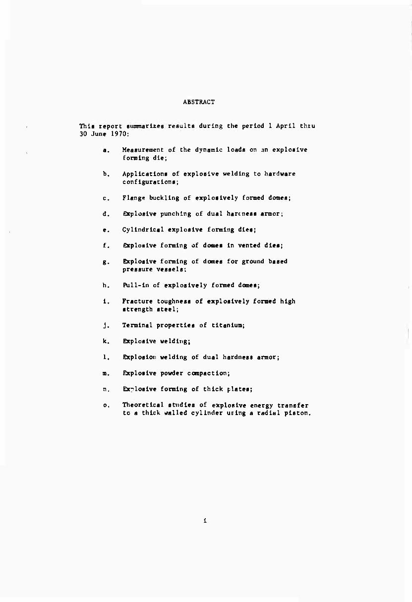
ABSTRACT
This report fummarlzeB results during the period 1 April thru 30 June 1970:
a. Measurement of the dynamic loads on an explosive forming die;
b. Applications of explosive welding to hardware configurations;
c. Flange buckling of explosively formed domes;
d. Qcploslve punching of dual bareness armor;
e. Cylindrical explosive forming dies;
f. Explosive forming of domes In vented dies;
g. Explosive forming of domes for ground based pressure vessels:
h. Pull-In of explosively formed domes;
1. Fracture toughness of explosively formed high strength steel;
J. Terminal properties of titanium;
k. Explosive welding;
1. Explosion welding of dual hardness armor;
m. Explosive powder compaction;
n. Explosive forming of thick plates;
o. Theoretical studies of explosive energy transfer to a thick walled cylinder UElng a radial piston.
CONTENTS
Abstract
Contents
MARTIN MARIETTA CORPORATION
1. Measurement of the Dynamic Loada on an Explosive Forming Die
2. Applications of Explosive Welding to Hardware Configurations
11. UNIVERSITY OF DENVER
6
7
8
9
10
11
Flange Buckling of Explosively Formed Domes
Explosive Punching of Dual Hardness Armor
Cylindrical Explosive Forming Dies
Explosive Forming of Domes in Vented Dies
Explosive Forming of Domes for Ground Based Pressure Vessels
Pull-In of Explosively Formed Domes
Fracture Toughness of Explosively Formed High Strength Steel
Terminal ?ropertlcB of Titanium
Explosive Welding .......
Explosion Welding of Dual Hardness Armor
Page
I
11
6
7
Explosive Powder Compaction
8
8
9
10
1?
14
15
11
CONTENTS
Page
12. Explosive Foming of Thick Plates 16
13. Theoretical Studies of Explosive Energy Transfer to A Thick Walled Cylinder Using A Radial Piston 16
Figure
I.
II.
1. Blank and Die St re in-Time History Recorded Slnultancously (Raw Data)
2. 200X Micrograph of Explosive Weld of .OO1) In. OFHC Copper
• • • 3. 20X Micrograph of Explosively Welded
Corner Joint (.125 in. Mild Steel)
4. 200X Micrograph of Explosively V>ldcd Corner Joint (.125 In. Mild Steel) .... 5
5. Effect of Explosive Forming on Impact Energy Absorbed by HY 80 Steel 11
6. Use of Radial Piaton for Explosive Energy Transfer to Thick Walled Tube 17
ill

Lv^^-L - ^mmmmfmm , M^ *■ -" ( .
MARTIN MARIETTA CORPORATION
1. Measurement of the Dynamic Loads on an Explosive Forming Die
Principal Investigators: L. Chlng, D. Bouma
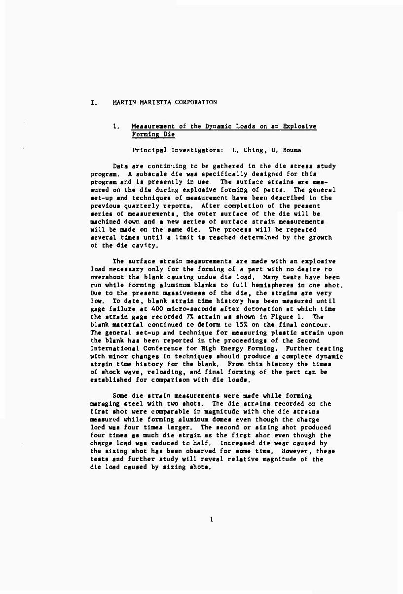
Data are continuing to be gathered In the die stress study program. A subscale die was specifically designed for this program and Is presently In use. The surface strains are mea- sured on the die during explosive forming of parts. The general set-up and techniques of measurement have been described In the previous quarterly reports. After completion of the present series of measurements, the outer surface of the die will be machined down and a new series of surface strain measurements will be made on the same die. The process will be repeated several times until a limit Is reached determined by the growth of the die cavity.
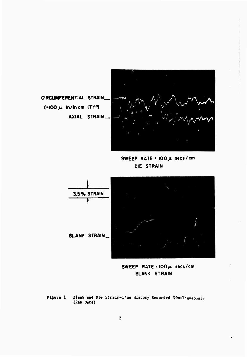
The surface strain measurements are made with an explosive load necessary only for the forming of a part with no desire to overshoot the blank causing undue die load. Many tests have been run while forming aluminum blanks to full hemispheres In one shot. Due to the present masslveness of the die, the strains are very low. To date, blank strain time history has been measured until gage failure at 400 micro-seconds after detonation at which time the strain gage recorded 77. strain as shown In Figure 1. The blank material continued to deform to 15% on the final contour. The general set-up and technique for measuring plastic strain upon the blank has been reported In the proceedings of the Second International Conference for High Energy Forming. Further testing with minor changes In techniques should produce a complete dynamic strsln time history for the blank. From this history the times of shock wave, reloading, and final forming of the part can be established for comparison with die loads.
Some die strain measurements were made while forming maraglng steel with two shots. The die strains recorded on the first shot were comparable In magnitude wlMi the die strains measured while forming aluminum domes even though the charge lord was four times larger. The second or sizing shot produced four times as much die strain as the first shot even though the charge load was reduced to half. Increased die wear caused by the sizing shot has been observed for some time. However, these tests and further study will reveal relative magnitude of the die load caused by sizing shots.
CIRCUMFERENTIAL STRAIN_|
C-IOOM i»i/in.cm (TYR
AXIAL STRAIN _| u ^ ^ > "A
A Wvyy /vy^/wv1
3.5% STRAIN
f
BLANK STRAIN.
SWEEP RATE« 100 M sees/cm
DIE STRAIN
SWEEP RATE«I00AL »ec$/cm BLANK STRAIN
Figur« 1 Blank and Die Strain-Tfue History Recorded Simultaneously (Raw Data)
2. Applications of Explosive Welding to Hardware Configurations
Principal Investigator: W. Simon
a. Lap Joint for Construction of Conical Ring from OFHC Copper (.005 In. thick)
Figure 2 200X Micrograph of Explosive Weld of .005 in. OFHC Copper
Figure 2 shows the weld obtained in this ap- plication. The bond line is horizontal along the center of the sample. This weld is now being used to construct cylindrical copper rings which are then stretched over a die to obtain a conical ring. The plastic strain in the stretching process is approxi- mately 1^7.. No weld failures have occurred in the fabrication of six rings.
Explosive Weld of Corner Joint with Mild Steel (.125 in. thick)
Figure 3 20X Micrograph of Explosively Welded Corner Joint (.125 in. Mild Steel)
In some applications it would be desirable to use explosive weld* t) construct angle Joints. Figures 3 and 4 show the results of the first attempt at a corner Joint. It can be seen that the explosive loading was too low, but a weld was obtained. One of the important characteristics of this configuration is that the base plate is its own mandrel, since its length is in the direction of the application of the explosive loading. No buckling occurred in either plate. The advantages
Ah . ■
WH-* ' . - > - ..:• ^ ^S: • til
^ ^ - • 'mi
N
Figure 4 200X Micrograph of Exploalvely Welded Corner Joint (.125 In. Mild Steel)
of Joint welds without ualng a mandrel are obvloui, particularly for large and heavy plates. Work !■ continuing on this application. Appllcatloni to oblique joints will be Investigated.
II. UNIVERSITY OF DENVER
1. Flange B ckllng of ExploBlvely Formed Dornet
Principal Investigator- M. Kaplan
Graduate Student: H. Boduroglu
The analysis of the stress and strains In the pre-buckled flange has been coaplctely finished. The resulting expressions are relatively almple analytically and agree very veil with experimental resulta. The buckling analysis hai been formulated In terms of the principle of virtual work. The buckled mode shape will be assumed in term« of coefficients which will be choaen so at to render the virtual work Integral stationary. The resulting equations should lead to a standard eigenvalue problem for determining the onset of wrinkling.
2. Exploalve Punching of Dual Hardneas Armor
Principal Investigator: W. G. Howell
Post Doctoral: A. R. Dowling
To test the theory that bad explosive to liner contact was causing the small penetrations produced by the circular con- figuration compared with linear wedge segments, Detasheet was cut in the shape of conical sections to fit the contours of the liner. This appeared to give much Improved contact with the liner material, yet the results of penetration tests were no different. In addition, two charges were covered with lead aheet in order to confine the gases better and hopefully to ac- celerate the liner material for a longer period. Here again, though, the penetration achieved waa the same.
Since 3/8 in. material with a hardness of Rc45 was per- forated using a complete charge, it seems probable that the depth of penetration produced by the shaped part of the charge Is of little importance and that the central charge provides moat of the cutting action. This possibility will therefore be examined by attempting to perforate 1/2 in. Rc50 steel by Increasing the weight of explosive in the central part of the complete charge. Since It is known that the Jet penetration in such hard material
la small, three cape, equally spaced around the apex of the wedge, can be used to initiate the charge as the deviation from a circular shape caused by removing the plane wave generator will be negligible.
3. Cylindrical Explosive Forming Dies
Principal Investigator: J. A. Weese
Graduate Student: R. E. Knight
The strain-time history of the workpiece was investigated by placing strain gages inside the workpiece. The workpieces were found to expand with a strain rate of about 1000/sec to a strain of 0.016, where an abrupt change in strain rate to ap- proximately 10,000/sec was observed. The gages all failed at a strain of approximately 0.04. The failure was apparently due to a strain rate effect in the adhesive or backing of the gage. Different adhesives and arrival time methods are under investi- gation.
4. Explosive Forming of Domes in Vented Dies
Principal Investigator: A. A. Ezra
Graduate Student: P. Hardee
Primary attention during this period has been devoted to determining a mathematical model for the problem. In an attempt to do this, a one-dimensional approach has been taken and an experiment formulated to verify the results predicted by the model. With this information it is hoped that one can determine the general parameters affecting the movement of the gas out of the cavity between the blank and the die.
The one-dimensional experiment is presently under development and will involve a piston accelerated into a cylinder with an orifice at the end. The time-velocity history of the piston will be determined and compared with the mathematical prediction. The computer program to pr.diet the movement of the piston has been formulated for the closed end case and is being expanded to include the case with an orifice of given size.
5. Exploetve Forming of Domes for Ground Based PresBure Vessels
Principal Investigator: A. A. Ezra
Post Doctoral: A. R. Dowllng, L. L. Altlng
Faced with competing against conventionally formed tank heads, It was apparent that a major economical handicap of ex- plosive formed domes would be the material wastage Incurred. The most commonly required tank head shape Is a dome terminating In a straight cylindrical portion, the skirt, which can be welded directly to the tank body. The normal explosive forming process produces domes with a flange and for the majority of vessels this would have to be trimmed off and be wasted.
The experimental program was directed toward minimizing this waste. To date, experiments have been performed using hot rolled steel plate and a diameter to thickness ratio of 110 in which, after forming, the outside edge of the flange came to rest at the start of the die opening. Thus, the only waste was that material bent over the curved entry into the die cavity and, by reducing the draw radius the waste could be reduced still further. However, a straight cylindrical section was not obtained and work will continue on this aspect. In addition, two other systems will be used to try to eliminate the flange altogether—one of which is expected to be useful at high diameter to thickness ratios (above 200), the other for ratios less than 100.
6. Pull-in of Explosively Formed Domes
Principal Investigator: M. Kaplat.
Graduate Student: S. Kulkarni
Hill's principle of maximum rate of plastic work is being used as the basis for an approximate solution to the pull-in problem. The constraints on the problem are that the middle surface of the dome is a portion of a sphere, the shear stress vanishes across the thickness, and the forming process is quasi- static. The last assumption is based on the experimental result that identically shaped statically and dynamically formed (L/D ■ 1/6) domes have the same pull-in despite the fact that their strain fields are somewhat different.
The Raylelgh-RltB method is being used to find an approxi- mate velocity field which satisfies the boundary conditions and renders the work integral a maximum. The rate of work in the flange is known in terms of the rate of pull-in from the flange buckling analyses. The rate of pull-in is related to the velocity field in the dome by matching velocities at the flange-dome inter- section.
7. Fracture Toughness of Explosively Formed High Strength Steel
Principal Investigator: H. Otto
Graduate Student: R. Mikesrll
Impact tests were conducted on explosively formed and cold rolled HY 80 steel to determine the ductile to brittle transition (DBT) temperature of this steel as a function of forming. Speci- mens were cut from two domes, one that had been formed in water with a standoff and the other that had been formed in air with a sizing operation in water. Cold rolled specimens were cut from stock that had been rolled to the same effective strain as the explosively formed stock, (c* ■ .066) It must be pointed out that all specimens were taken parallel to the rolling direction, so the uniaxial strain in this direction was greater in the cold rolled stock.
All of the specimens were machined to 2.165 x 0.394 x 0.197 in. bars and then heat treated. The heat treatment con- sisted of austenltizing at 1655°? for 36 minutes, water quenching, and then tempering at 12950F for 40 minutes. Hardness readings after heat treatment were approximately the same (cold rolled - Rc21.5, explosively formed - Rc22.0). Notches for Charpy impact were ground in the specimens after heat treatment. A standard 0.01 in. radius notch was used.
A dewar filled with liquid nitrogen was used to chill the specimen. For calibration, copper constantan thermocouples were soldered adjacent to the notch to determine the temperature- time relationship for achieving a particular test temperature. The temperature differential across the specimen as it warmed was less than 1 F.
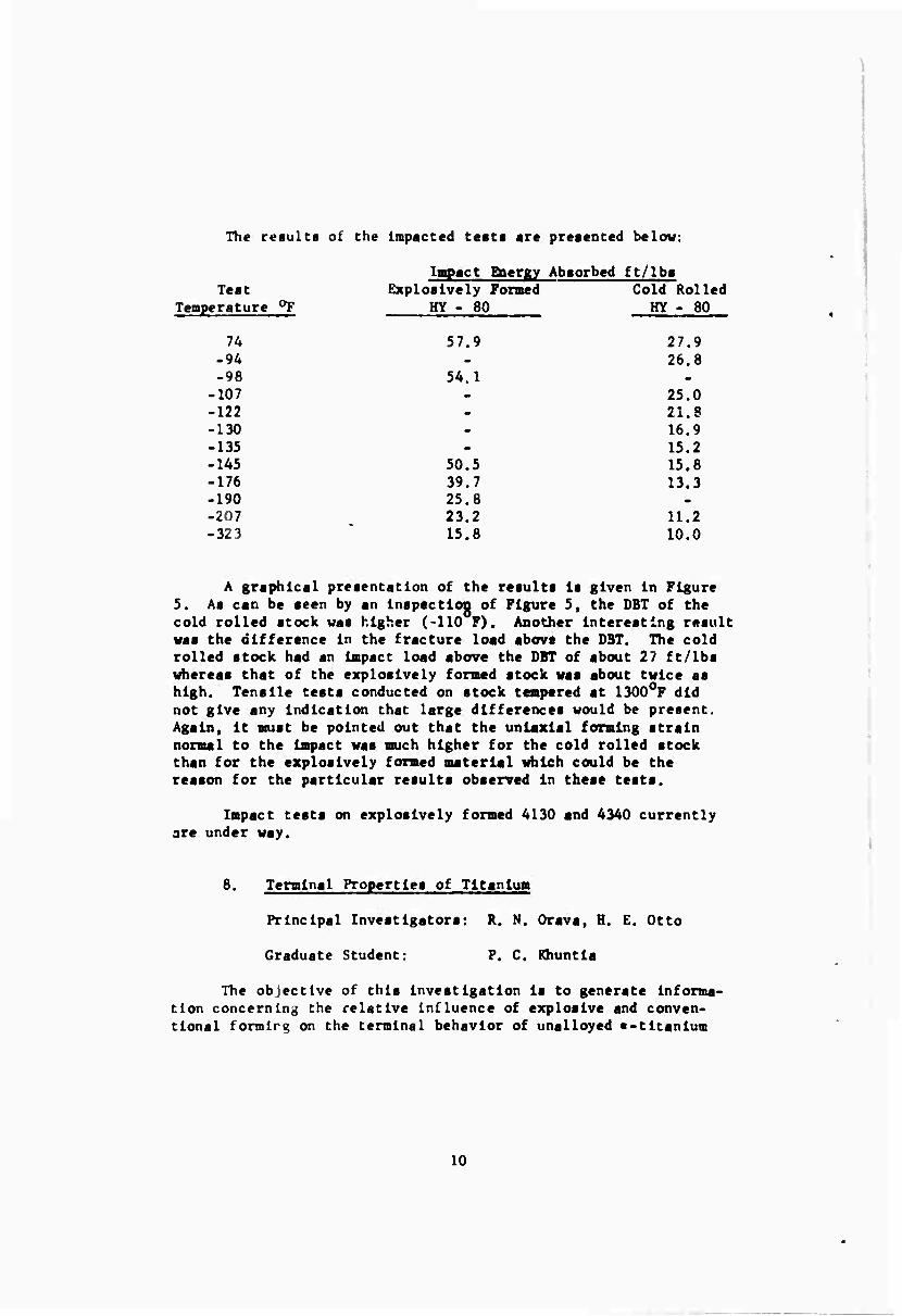
The results of the impacted tests are presented below:
Impact Biergy Absorbed ft/lbs Test Explosively Formed Cold Rolled
Temperature OF HY - 80 HY - 80
54.1
27 9 26 8
25.0 21 8 16 9 15 2 15. 8 13 3
11. 2 10 0
74 57.9 -94 -98
-107 -122 -130 -135 -145 50.5 -176 39.7 -190 25.8 -207 23.2 -323 15.8 10.0
A graphical presentation of the results is given in Figure 5. As can be seen by an inspection of Figure 5, the DBT of the cold rolled stock was higher (-110 F). Another interesting result was the difference in the fracture load above the DST. The cold rolled stock had an impact load above the DBT of about 27 ft/lbs whereas that of the explosively formed stock was about twice as high. Tensile tests conducted on stock tempered st 1300°? did not give any indication that large differences would be present. Again, it must be pointed out that the uniaxial forming strain normal to the impact was much higher for the cold rolled stock than for the explosively formed material which could be the reason for the particular results observed in these tests.
Impact tests on explosively formed 4130 and 4340 currently are under way.
8. Terminal Properties of Titanium
Principal Investigators: R. N. Orava, H. E. Otto
Graduate Student: P. C. Khuntia
The objective of this investigation is to generate informa- tion concerning the relative Influence of explosive and conven- tional formlrg on the terminal behavior of unalloyed «-titanium
10

100
80
c UJ
60-
40
20
# Explosively formed
O Cold rolled
-400 -300 -200 -100 Temperature, " F
100
Figure 5 Effect of Explosive Forming on Impact Energy Absorbed by HY 80 Stetl
11
(TMCA 50A) and •-? titanium alloy (6A1-4V). The study Includes the evaluation of microatructure, hardness, tensile flow char- acteristics, stress corrosion cracking auaceptibility, and thermal response. Test samplea were selected from explosively free-formed and from iaostatically rubber-pressed domes. The detailed procedures and results will be presented in the annual report. Sane of the more recent findings are outlined below.
The study of the susceptibility of unformed, explosively formed, and iaostatically formed Ti-6A1-4V to cracking in met Ha- noi-0.057. HC1 has been completed. An examination of the mean failure times, t,, revealed behavior sim'lar to that reported previously for unalloyed Ti. Specifically:
a) In all of four aeta of experiments
t_ (explosively formed) ^ tv (unformed);
b) In three of four sets
tp (isostatically formed) ^ tp (unformed);
c) In all of four aeta
tp (explosively formed) > t (isostatically formed).
The following conclusiona were drawn from a statistical analysis of the above data:
■ ) Explosive forming to effective straina of 2.5 or 57. enhances the resistance of annealed 6A1-4V to cracking in methanol/HCI solutions;
b) Isoatatic forming to effective strains of 2.5 or 57. leaves the resistance unaltered;
c) Explosive forming, as compared with isoatatic forming to an equivalent atraln, probably does not influence cracking susceptibility; if anything, resistance may be slightly improved.
It should be noted that th» strain effect would have been more pronounced had the tests been conducted at the same absolute stress level rather than at the aame fraction of the unformed or as-termed yield atrese.
12
A compariaon of the mlcroatructurea of laoatatlcally formed and unlaxially pulled T1-50A disclosed a lower twin density In the latter. This would suggest a »tress state effect, In agreement with some recent results ■ ' in the literature for the alpha alloy T1-5A1-2.5Sn. However, on increasing the strain rate in the tensile test to 10"2 sec" in order to correspond to that during isostatic forming, it was found that the twin densi- ties were comparable. Thus, neither the above data, nor the microatructural observations after explosively forming, indicate that the state of stress plays any significant role in the num- ber of twins introduced during the deformation of T1-50A. There- fore, the high incidence of twinning during the explosive forming of domes is probably characteristic of the rate of forming and applies equally well to other configurations which are fabricated explosively. There is no indication as yet that the presence of deformation twins is detrimental to the behavior of this material. However, until other properties such as fracture, fatigue, and creep are evaluated, any conclusion in this regard would be premature.
9. Explosive Welding
Principal Investigator: S. H Carpenter
Graduate Students: V. H. Winchell, M. Nagarkar
Diffusion Studies
Work has continued on studying the metallurgical reactions which occur at the explosive weld interface at high temperatures. The main object to dste has been to investigate the diffusion at the interface. Commercially roll bonded copies of Cu-Ni, Fe-Ti, and Fe-Al have been supplied free of charge by Texas Instruments, Inc. Samples cut from the roll bonded material have been ex- plosively bonded giving a sample with three interfaces. The first interface is a roll bonded interface which has also been shocked and deformed like a cladder plate, the second interface is the explosive weld interface, and the third interface is a roll bonded interface which has been shocked like a base plate. After explosive welding, the samples are heat treated and compared
(1^G. F. Pittinato and S. F. Fredrick, Trans TMS-AIME, 245. 2299, 1969.
13

wich Che conventionally bonded material. Using Chit approach one can hopefully separate ouC Che effects of a) longitudinal plastic icraln of the cladder plate, b) tha ■evere cold working at the explosive weld Interface, and c) the high pressure shock wave.
To date. Cu-Nl samples have been welded and heat treated at 5000C, 750 C, and 900 C. Microprobe work has been carried out on the Cu-Nl samples to measure the diffusion rone width at all three Interfaces as well as the standard. The data are now being analyzed. The next couple to be investigated will be Fe-Al where the kinetics of intermetallic compound formation will be studied.
Strains
Work has contlqued on examining the plastic strains in- duced in the cladder plate during the explosive welding opera- tion. A cladder plate 24 x 8 x 1/4 in. of cold rolled steel was welded to a base plate of identical site and composition. A grid of 18 holes (0 .0135 in. diameter) was used to measure the plastic strain. The results are sütllar to those reported earlier for the smaller aluminum plate. The plate was found to elongate slightly and quiCe uniformly up to the last few inches where significant elongation occurs. Measurements also showed a trans- verse elongation at the center portion of the weld. Current work Is directed to continuing this type of study on a strain rate sensitive material such as titanium.
10. Explosion Welding of Dual Hardness Armor
Principal Investigator: R. H. Wlttman
During the pasc quarter, experiments have been conducted preparatory Co Che making of a 350 maraging 8teel/Ti-6Al-4V dual hardness armor plate for ballistic testing. To create a strong, touch explosion weld in this system, experiments indicate it will be necessary to use an intermediate foil layer between the steel and titanium.
A dual hardness armor plate for ballistic testing has Just been explosion welded in a two-step sequence using a mild steel sheet for the interlayer. The first explosion welding sequence Involved cladding a 3/16 in. thick Ti-6A1-4V plate .ith a 0.028 In. chick layer of mild steel. A duPont free running dynamite
14
with 4500 ft/sec detonation velocity was the explosive used. To complete the armor plate, a 1/8 in. thick, 350 maraging steel plate in the solution treated condition was explosion welded to the mild steel surface of the Ti-6A1-4V bsse plate. A Trojan Powder Co. nltrostarch dynamite with 11,500 ft/sec detonation velocity was used in this welding sequence. After inspection, trimming away peripheral non-bond, and flattening, the composite plate will be heat treated at 9250F for three hours to develop maximum hardness in the maraging steel.
11. Etplosive Powder Compaction
Principal Investigator: H. Otto
Graduate Student: D. Ultkowsky
Several steel compacts, nominally 1/4 and 1/2 in. in thickness, were made during this report period. The same pre compaction load was used throughout. Explosive loadings of 40% Red Cross Extra dynamite were maintained at explosive to metal ratios of 0.6, 0.8, and 1.1 : 1. Post compaction densi- ties of the 1/2 in. thick compacts were 7.46, 7.65, and 7.78 g/cc, respectively. The percent of theoretical density ranges from 93.5 to 97.67.. Comparing this range of densities with the 1/4 in. compacts (94 to 98%), a slight decrease in compaction is observed as the thickness Increases.
Sintering the compacts in a reducing atmosphere at 2050oF indicated no perceptible change in density. Tests are currently under way on vacuum sintering the compacts.
In addition to the steel, 2024 aluminum machine chips have been compacted successfully. Green strength is very good, with the compacts being able to be machined without sintering first.
A WC-Co compact was made to evaluate explosive compaction as a method of producing carbide tool material. Good green strength was realized even though the compaction was 84% of theoretical. Liquid phase sintering is being used for the post compaction heat treatment.
15
12. Explosive Forming of Thick Platas
Principal Investigator: R. J. Green
A theoretical Inveetlgation has been done on a loosely clamped, rlgld-plastic circular plate imbjected to a paraboli- cally distributed blast loading. Based on the assumption that bending alone produced the final shape, i.e., no change in plate thicknessi a closed form solution was obtained. The results, compare well with published experimental data by Florence which were obtained from the deformation of a circular plate by sheet explosive placed on it with an intervening buffer and detonated at the center.
A paper based on this has been submitted to the Journal of the Engineering Mechanics Division of the American Society for Civil Engineers.
13. Theoretlccl Studies of Explosive Energy Transfer to A Thick Walled Cylinder Using a Radial Piston
Principal Investigator: H. S. Click
Graduate Student: V. D'Souza
A computer program has been developed which permits the calculation of the dynamic changes that occur when a radial piston is employed in the explosive expansion of thick walled cylinders. The computer program is based on rough fluid- and solld-mechanicil models, and is useful up to the point at which elastic unloading of the thick walled tube begins. The primary parameters (see Figure 6) in the computer program are:
a) The initial explosive pressure produced within the radial cylinder;
b) The dimensions, density, and yield stress of the wall of the radial piston;
c) The thickness of the water layer;
d) The dimensions, density, and yield stress of the thick walled tube.
^2'A. L. Florence, "Circular Plate Under a Uniformly Distributed Impulse," International Journal of Solids and Structures. Vol. 2, pp. 37-47 (1966).
16
•a 01
U
o
ft)
c
00 kl
01 >
o
a
)-> o
c o
X)
o 01 ID
tu u 3 00
Computer calculations have been performed for the 20% model that has been tested experimentally. An average yield stress of 60,000 psl was assumed for the stainless steel piston, and a yield stress of 170,000 psi was assumed for the thicK walled tube. The calculations were carried out for three initial pressures, p0, -270,000 psi, 135,000 psi, and 75,000 pai. Also, a calculation was performed for a wall thickness which was twice the experimental value for an initial pressure of 135,000 psi. Additional calculations were carried out for the case of a lead radial piston in which the yield strength of the lead was assumed to be 2000 psl. Computations were carried out for the 207. model case for initial pressures of 135,000 psi and 75,000 psi; also, a computation was performed for an initial pressure of 75,000 psi and for a wall thickness which is twice that used in the 207. model tests.
The computations show that the water pressure undergoes a damped oscillatory variation which has a peak magnitude which is approximately twice the initial explosion pressure. The number of oscillatory cyclea before elastic unloading begins increases strongly with increasing p and decreases moderately with increasing radial piston wall density. There is a relatively small effect of initial pressure, radial piston wall thickness, and radial piston wall density on the oscillatory frequency. In the 270,000 psi, stainless steel radial piaton case, water pres- sures dropped to levels at which cavitatlon would occur; in the other cases, the minimum water pressures were sufficiently grest so that no cavltation would take place.
18
UnclMBlfltd SgcwÜ» Cl—ification
DOCUMENT CONTROL D; TA - R&D (t»euHiy clmtmlllcailon of Mil*, body ol abafracl an* ItMmmtnt mnnoitiion mill 6« mnl»n4 Wian #>• •«•«•II raport I« cto«*«/«*«*;
I OmniNATINC *CTIVITV (CotwV* »ulkeO M«rtln Marietta Corporation Denver Division University of Denver Denver, Colorado Denver, Colorado
2« MC)>OnT ttCUniTV C L/SMI^lC*TION
Unclassified I ft anour
N/A i niPomt TiTLe
Center for High Energy Forming
4 OCSCniPTIVC NOTE$ (TYV ol rapen and Incluiiv» dmimm)
Twentieth Quarterly Report of Technical Progress July 1, 1970 S AUTHOWS; O.«*! nan«. Ilnl nrnrn». Iniilmh
Mote, Jimmy D.
• ntfonr DATE
July 1. 1970 7« TOTAL NO Or »AOKt
18 76. MO. or nsrt
|a CONTNACT OK ORANT NO.
ft. PHOJICT NO AMRA CR 66-05/23
t*»)
• ft OTHtM ntVOMT MOfW (A ny »ttUf WMWtl» I thla mperl) ,
10 AVAILAaiLITV/LIMITATION NOTICS*
It lU^LCMINTARV NOTtt 12. •P9MSONINO MILITANV ACTIVITY
Army Materials and Mechanics Research Center
Watertown. Massachusetts 02172 I» ASITRACT
This report sumnarices results during the period 1 April thru 30 June 1970:
«. Measurement of the dynamic loads on an explosive forming die; b. Applications of explosive welding to hardware configuration; c. Flange buckling of explosively formed domes; d. Explosive punching of dual hardness armor; e. Cylindrical explosive forming dies; f. Explosive forming of domes in vented dies; g. Explosive forming of domes for ground based pressure vessels; h. Pull-in of explosively formed domes; 1. Fracture toughness of explosively formed high strength steel; J. Terminal properties of titanium; k. Explosive welding; 1. Explosion welding of dual hardness armor; m. Explosive powder compaction; n. Explosive forming of thick plates; o. Theoretical studies of explosive energy transfer to a thick
walled cylinder using a radial piston.
DD rottm t JAN «4 1473 UnclawHlflfd,
Security Classification
UiudMJuinjuL- l»cuilty Cuwiiflcatian
i« KIV «onot
LINK A
•out «•T
LINK I
MObl WT
UNKC NOLI • T
Energy Requirements
Energy Transfer
Ductility
Strain Rate Effects
Explosive Welding
Mechanical Properties Before and After Forming
INSTRUCTIONS I. ORIGINATING ACTIVITY: Entw liw itM« and «ddr«*« of lh« cemtacter, •ubconiracior, grant«*, Dapartmant of D» (anaa activity or othar organifatlon fcerporala author) laaulnc tha rapeit.
3a. REPORT SBCUHTY CLAiSIFICATlON: Bntor tha «var- all aacurily claaalflcailen of tha raport. Indtcata whathar "Raatnctad Data" la Includad Markln« la to b« In accord- anc» with approprlata aacurlty ragulatlona.
26. GROUP: Automatic downgrading la apaciflad In DoD Dt- ractiv« S200.10 and Armad farea« Industrial Manual. Entar lh« group numbar. Alao, whan apptlcabt«, ahow that optional marking« hav« b««n u««d (or Group 3 and Group 4 «■ author- icad.
3. REPORT TITLE: Entar tha complot« r«port lltl« In all capital lattara. Titlaa in all ca««a ahould b« uncUaalflad. If « m««nlng(ul titl« cannot ba aalactad without clasaiflca- tlon, «how titl« claaaiflcalion In «11 capital« in paranlhaala lmm«di«l«ly following tha Utla.
4. DESCRIPTIVE NOTE& If *>proprlal«, «ntar tha typa of report, e.g.. intarlm, progr«««, «ummary, annual, or final. Giv« the inclusive date« whan ■ ■pacific reporting period la covered.
i. AUTT JR(8); Enter the ne«te(«) of «uthoK«) «« «hewn on or in the report. F.ntei <eat name, flral name, middle Initial. If attlltary, «how rank mni branch of aarvice. The name of the principal . <lhor in an abaolute minimum requirement.
6. REPORT DATE; Enter (he date of tha raport aa day, month, ycer, or month, year. If more than one deta appear« on the report, uae date of public ution.
7a. TOTAL NUMBER OF PAGtS: The total page count should follow normet pagination procedurea, i.e., entar tha numbei of pegea containing informatiotw
76. NUMBER OF REFERENCE^ Enter the total number of references cited in the report.
S«. CONTRACT OR GRANT NUMBER: If approprlata, enter the eppUcable number of the contrect or grant under which tl<e repiri wes wrltlen.
S6. ft, fli id. PROJECT NUMBER: Enter the appropriate mllKary department Identification, such ae project number, subprtiject number, system numbers, task number, etc.
9e. ORIGINATOR'S REPORT NllMBER(S): Enter the offl- cist rapurl number by which the document will be Identified end controlled by the orlglnetlng activity. Thla number must be unique to ihlt report.
96. OTHER REPORT NUMBERO): If the report haa been esslgned any other report number« (»llher by Ihr originator or by lha tpontor,', also enter thl« number(a).
10. AVAILAniLfTY'LIMlTATIOV NOTICES: Enter any Um. nation» on furlhr. r'naemination of the report, other then fhoa«
lmpo«ed by aacurlty claaalflcation, ualng «tandard atatamanta auch a«:
(1) "Ouallflad requaatar« may obtain eoplaa of thl« raport from DDC"
(2) "Foreign «nnouncamant and dlasaminatlon of thl« report by DDC la not authorlaaA"
(3) "U. S. Government aganclaa may obtain eoplaa of thla raport directly from DOC. Othar qualified DDC uaar« ahall requeat through
(4) "U. 8. military aganclaa may obtain eoplaa of thla raport directly from DDC Othar qualified uaera ahall request through
(S) "All distribution of thla raport la controlled Qual- ified DDC uaera ahall request through
If the report haa been furnished to the Office of Technical Services, Department of Commerce, for «sie to the public, indi- cete this fact and enter the price. If known.
It SUPPLEMENTARY NOTES: U«e (or additional explana- tory note«.
12. SPONSORING MILITARY ACTIVITY: Enter th« name of the depertmental project office or laboratory aponaorlng fper- Ing lor) the reeeerch end development. Include «ddre««.
13 ABSTRACT: Enter an abstract giving • brief end tactual «umn sry of the document indicative of the report, even though it may alao appear elaewhrre In the body of the technical re- port. If eddlUonel apace is required, • contlnu«tlon sheet «hall be st'sched.
It Is highly desirable that the «batract of claaaified reporta be uncleaalfied. Each paragraph of the abatract ahall end with en Indication of the mllltery aecurlty classlficstlon of the In- formation in the paragraph, represented as rrs; ($), (C). or (V)
There Is no limitation on the length of the abatract How- ever, the euggeated length ia from ISO to 225 word«.
14 KEY WORDS: Key worda are technically meaningful terma or abort phraaea that charecterixe a report and may be used aa Inde« entries for cstslnglng the raport. Key word« muat be aelected ao that no aecurlty cl«««lflc«tlon 1« required. Identi- flera, such aa equipment model deslgnsllon, trade name, military project code neme, geographic location, may be uaed es key words but will be followed bv en indication of technlcel con- text. The atalgnment of 'inks, rulss, snd weights Is optional.
Uncle-sifled Security Classification