treatment of internal fires for nuclear power …treatment of internal fires in probabilistic safety...
TRANSCRIPT

TREATMENT OF INTERNAL FIRESIN PROBABILISTIC
SAFETY ASSESSMENTFOR NUCLEAR POWER PLANTS

The following States are Members of the International Atomic Energy Agency:
AFGHANISTANALBANIAALGERIAARGENTINAARMENIAAUSTRALIAAUSTRIABANGLADESHBELARUSBELGIUMBOLIVIABOSNIA AND
HERZEGOVINABRAZILBULGARIACAMBODIACAMEROONCANADACHILECHINACOLOMBIACOSTA RICACOTE D’IVOIRECROATIACUBACYPRUSCZECH REPUBLICDEMOCRATIC REPUBLIC
OF THE CONGODENMARKDOMINICAN REPUBLICECUADOREGYPTEL SALVADORESTONIAETHIOPIAFINLANDFRANCEGABONGEORGIAGERMANYGHANAGREECEGUATEMALAHAITI
HOLY SEEHUNGARYICELANDINDIAINDONESIAIRAN, ISLAMIC REPUBLIC OF IRAQIRELANDISRAELITALYJAMAICAJAPANJORDANKAZAKHSTANKENYAKOREA, REPUBLIC OFKUWAITLATVIALEBANONLIBERIALIBYAN ARAB JAMAHIRIYALIECHTENSTEINLITHUANIALUXEMBOURGMADAGASCARMALAYSIAMALIMALTAMARSHALL ISLANDSMAURITIUSMEXICOMONACOMONGOLIAMOROCCOMYANMARNAMIBIANETHERLANDSNEW ZEALANDNICARAGUANIGERNIGERIANORWAYPAKISTANPANAMA
PARAGUAYPERUPHILIPPINESPOLANDPORTUGALQATARREPUBLIC OF MOLDOVAROMANIARUSSIAN FEDERATIONSAUDI ARABIASENEGALSIERRA LEONESINGAPORESLOVAKIASLOVENIASOUTH AFRICASPAINSRI LANKASUDANSWEDENSWITZERLANDSYRIAN ARAB REPUBLICTHAILANDTHE FORMER YUGOSLAV
REPUBLIC OF MACEDONIATUNISIATURKEYUGANDAUKRAINEUNITED ARAB EMIRATESUNITED KINGDOM OF
GREAT BRITAIN AND NORTHERN IRELAND
UNITED REPUBLICOF TANZANIA
UNITED STATESOF AMERICA
URUGUAYUZBEKISTANVENEZUELAVIET NAMYEMENYUGOSLAVIAZAMBIAZIMBABWE
The Agency’s Statute was approved on 23 October 1956 by the Conference on the Statute of theIAEA held at United Nations Headquarters, New York; it entered into force on 29 July 1957. TheHeadquarters of the Agency are situated in Vienna. Its principal objective is “to accelerate and enlarge thecontribution of atomic energy to peace, health and prosperity throughout the world’’.
© IAEA, 1998
Permission to reproduce or translate the information contained in this publication may beobtained by writing to the International Atomic Energy Agency, Wagramer Strasse 5, P.O. Box 100,A-1400 Vienna, Austria.
Printed by the IAEA in AustriaSeptember 1998STI/PUB/1062
TREATMENT OF INTERNAL FIRESIN PROBABILISTIC
SAFETY ASSESSMENTFOR NUCLEAR POWER PLANTS
SAFETY REPORTS SERIES No. 10
INTERNATIONAL ATOMIC ENERGY AGENCYVIENNA, 1998

VIC Library Cataloguing in Publication Data
Treatment of internal fires in probabilistic safety assessment for nuclear powerplants. — Vienna : International Atomic Energy Agency, 1998.
p. ; 24 cm. — (Safety reports series, ISSN 1020–6450 ; no. 10)STI/PUB/1062ISBN 92–0–103298–6Includes bibliographical references.
1. Nuclear power plants—Fires and fire prevention. 2. Fire riskassessment. I. International Atomic Energy Agency. II. Series.
VICL 98–00203
FOREWORD
In 1974, the IAEA established a special Nuclear Safety Standards (NUSS)programme under which Codes (requirements) and a number of Safety Guides havebeen produced in the areas of governmental organization, siting, design, operationand quality assurance. The NUSS Codes and Guides are a collection of basic andderived requirements for the safety of nuclear power plants with thermal neutronreactors. They have been developed with the broadest possible internationalconsensus.
This broad consensus is one of the reasons for the relatively general wording ofthe main principles and requirements which may need further elaboration andguidance for application to specific nuclear power plants. In many areas, nationalregulations and technical standards are available, but often even these do not answerall questions and only the practice adopted in applying certain rules fully reflects theoutcome of the detailed consideration given to solving individual cases.
To present further details on the application and interpretation and on thelimitation of individual concepts in the NUSS Codes (requirements) and SafetyGuides, a series of publications that detail good practices has been initiated. It ishoped that many Member States will benefit from the experience presented in thesepublications.
The present report provides information on good practices in conductingprobabilistic safety assessment (PSA) for fires in land based nuclear power plants,and is intended for the professional staff who manage or perform PSAs. It isapplicable to both new and existing plants.
This Safety Report has been developed within the framework of the IAEAprogramme on fire safety in response to the increasing attention being given to therisk based approach, both in general safety assessment and in relation to a fire innuclear power plants. It supplements existing guidelines on this topic.
This publication has been prepared with the help of experts from engineeringand scientific organizations, regulators and plant operators, all with practicalexperience in the field of fire safety and fire protection in nuclear power plants. TheIAEA is grateful to all the experts who helped in the drafting and reviewing of thispublication.

CONTENTS
1. INTRODUCTION . . . . . . . . . . . . . . . . . . . . . . . . . . . . . . . . . . . . . . . . . 1
1.1. Background . . . . . . . . . . . . . . . . . . . . . . . . . . . . . . . . . . . . . . . . . . 11.2. Objectives . . . . . . . . . . . . . . . . . . . . . . . . . . . . . . . . . . . . . . . . . . 21.3. Scope . . . . . . . . . . . . . . . . . . . . . . . . . . . . . . . . . . . . . . . . . . . . . . 31.4. Structure . . . . . . . . . . . . . . . . . . . . . . . . . . . . . . . . . . . . . . . . . . . . 3
2. GENERAL OVERVIEW OF A FIRE PSA PROJECT . . . . . . . . . . . . . . 5
2.1. Methods . . . . . . . . . . . . . . . . . . . . . . . . . . . . . . . . . . . . . . . . . . . . 52.2. Main assumptions . . . . . . . . . . . . . . . . . . . . . . . . . . . . . . . . . . . . . 62.3. Project organization and management . . . . . . . . . . . . . . . . . . . . . . 72.4. Major procedural tasks . . . . . . . . . . . . . . . . . . . . . . . . . . . . . . . . . 8
3. PREPARATION PHASE (TASKS 1–4) . . . . . . . . . . . . . . . . . . . . . . . . . 12
3.1. Data collection and assessment (task 1) . . . . . . . . . . . . . . . . . . . . . 123.2. Definition of fire compartments and cells (task 2) . . . . . . . . . . . . . 153.3. Familiarization with the internal events PSA (task 3) . . . . . . . . . . 163.4. Inventory of equipment and cables (task 4) . . . . . . . . . . . . . . . . . . 25
4. SCREENING PHASE (TASKS 5 AND 6) . . . . . . . . . . . . . . . . . . . . . . . 26
4.1. Screening by impact (task 5) . . . . . . . . . . . . . . . . . . . . . . . . . . . . . 264.2. Screening by frequency (task 6) . . . . . . . . . . . . . . . . . . . . . . . . . . 30
5. DETAILED ANALYSIS (TASK 7) . . . . . . . . . . . . . . . . . . . . . . . . . . . . . 33
5.1. Background . . . . . . . . . . . . . . . . . . . . . . . . . . . . . . . . . . . . . . . . . . 335.2. Effects of passive intracompartmental protection features . . . . . . . 345.3. Relative location of equipment and cables . . . . . . . . . . . . . . . . . . . 355.4. Probability of a hot short . . . . . . . . . . . . . . . . . . . . . . . . . . . . . . . 365.5. Human actions . . . . . . . . . . . . . . . . . . . . . . . . . . . . . . . . . . . . . . . 365.6. Active fire protection measures . . . . . . . . . . . . . . . . . . . . . . . . . . . 375.7. Fire propagation event tree analysis . . . . . . . . . . . . . . . . . . . . . . . . 39
6. SPECIAL ISSUES . . . . . . . . . . . . . . . . . . . . . . . . . . . . . . . . . . . . . . . . . 39
6.1. Introduction . . . . . . . . . . . . . . . . . . . . . . . . . . . . . . . . . . . . . . . . . 396.2. Analysis of the control room . . . . . . . . . . . . . . . . . . . . . . . . . . . . 40

6.3. Cable spreading rooms and other sensitive plant locations . . . . . . . 406.4. Environmental survival of equipment . . . . . . . . . . . . . . . . . . . . . . 416.5. Fire induced explosions . . . . . . . . . . . . . . . . . . . . . . . . . . . . . . . . . 416.6. Interaction of the control systems . . . . . . . . . . . . . . . . . . . . . . . . . 426.7. Integrity of the containment . . . . . . . . . . . . . . . . . . . . . . . . . . . . . 426.8. Conducting a fire PSA in the event of incomplete information . . . 43
7. ANALYSIS OF THE RESULTS (TASKS 8 AND 9) . . . . . . . . . . . . . . . 43
7.1. Uncertainty analysis (task 8) . . . . . . . . . . . . . . . . . . . . . . . . . . . . . . 437.2. Sensitivity and importance analyses (task 9) . . . . . . . . . . . . . . . . . . 45
8. DOCUMENTATION OF THE ANALYSIS (TASK 10) . . . . . . . . . . . . . 46
8.1. Objectives . . . . . . . . . . . . . . . . . . . . . . . . . . . . . . . . . . . . . . . . . . . . 468.2. General principles . . . . . . . . . . . . . . . . . . . . . . . . . . . . . . . . . . . . . . 468.3. Organization of documentation . . . . . . . . . . . . . . . . . . . . . . . . . . . . 46
9. EX-CORE SOURCES OF RADIOACTIVE MATERIAL . . . . . . . . . . . . 48
Appendix I: INFORMATION REQUIRED FROM AND IN ADDITION TO THE INTERNAL EVENTS PSA MODEL . . . . . . . . . . . . . . . . . . . . . . . . . . . . 51
Appendix II: ESSENTIAL EQUIPMENT MALFUNCTIONSRESULTING FROM FIRE INDUCED DAMAGE TO NON-ESSENTIAL CIRCUITS . . . . . . . . . . . 54
Appendix III: USE OF DETAILED ANALYSIS METHODS . . . . . . . . . . . 59
Appendix IV: FIRE PROPAGATION EVENT TREE . . . . . . . . . . . . . . . . . 64
Appendix V: POTENTIAL FOR LOSS OF THEALTERNATE SHUTDOWN CAPABILITY DURING A CONTROL ROOM FIRE . . . . . . . . . . . . . . . . . . 69
REFERENCES . . . . . . . . . . . . . . . . . . . . . . . . . . . . . . . . . . . . . . . . . . . . . . . . 73
CONTRIBUTORS TO DRAFTING AND REVIEW . . . . . . . . . . . . . . . . . . . . 75
1
1. INTRODUCTION
1.1. BACKGROUND
Considerable attention has recently been devoted to the topic of fire safety atnuclear power plants, in particular to those plants that have been designed andconstructed according to earlier fire protection standards. It is important that acomprehensive fire safety assessment is performed for these plants at the earliestopportunity in order to document that the existing fire safety measures are adequateto ensure plant safety. Periodic updating of fire safety analyses has to be continuedthroughout the life of a plant to reflect all the changes made, as well as the currentrequirements of and the experience gained on fire safety.
The IAEA is endeavouring to promote an exchange of information on firesafety between different countries, as well as the use of various fire safety assessmenttechniques. The main objectives are to achieve a better understanding of the currentsituation, to identify those areas that need further development, and to promote themost effective and reliable techniques. Considerable effort has been made to developguidelines for the preparation and evaluation of a fire safety analysis for nuclearpower plants.
Systematic assessment of a fire hazard is one of the important elements inimplementing fire protection in plants. When applied at the plant design stage, itpermits integration of the proper protection concept into the design and ensures that,throughout all stages of design, construction and commissioning, problems areidentified and resolved. For plants in operation it is possible, through a systematic firehazard assessment, to identify the existing deficiencies in fire protection and toimplement practicable and worthwhile improvements in fire safety.
Deterministic and probabilistic techniques are used to assess a fire hazard. Thedeterministic fire hazard analysis, typically carried out first, is normally required bylicensing authorities and other safety assessors. It is usually developed early in thedesign of new plants, updated before initial loading of the reactor fuel, and thenperiodically or when relevant operational or plant modifications are proposed.Probabilistic safety assessment (PSA) for fire is undertaken globally to supplementthe deterministic fire hazard analysis.1 It should be noted that a fire PSA is recognizedas a tool that can provide valuable insights into plant design and operation, including
1 Throughout these guidelines the term fire hazard analysis is applied exclusively to thedeterministic assessment of fires, while the expressions fire risk assessment and fire PSA areused for the probabilistic safety assessment of fires.
identification of the dominant risk contributors, comparison of the options for riskreduction and consideration of the cost versus risk benefit.
Two publications devoted to the fire hazard analysis for nuclear power plantshave been developed as part of the IAEA Nuclear Safety Standards (NUSS)programme: Preparation of Fire Hazard Analyses for Nuclear Power Plants [1] andEvaluation of Fire Hazard Analyses for Nuclear Power Plants [2]. These publicationssupplement Safety Series No. 50-SG-D2 (Rev. 1), Fire Protection in Nuclear PowerPlants [3], by providing detailed information on the preparation and evaluation of afire hazard analysis at a nuclear power plant. They address a systematic approachbased on the deterministic technique.
No detailed information on conducting a PSA for fire in nuclear power plantsis provided in other PSA related IAEA publications: Procedures for ConductingProbabilistic Safety Assessments of Nuclear Power Plants (Level 1) [4] addressesPSA for internal events, and Treatment of External Hazards in Probabilistic SafetyAssessment for Nuclear Power Plants [5] outlines the general treatment of thosehazards external to a plant that are encountered and analysed most frequently:earthquakes, high winds, floods and person induced events. Since internal fire eventshave a localized effect on plant safety systems, no specific recommendations aregiven in Ref. [5] on the treatment of internal fire hazards.
The present report has been developed in response to the increased attentionbeing given to PSA worldwide. It is intended to facilitate implementation of the riskbased approach to fire safety assessment for both new and operating nuclear powerplants, and supplements existing IAEA publications on fire safety assessment.
1.2. OBJECTIVES
This Safety Report provides information on good practices in conducting aninternal fire PSA for land based nuclear power plants, as well as assistance inintegrating the threat of a fire into an existing internal events PSA. It is intended forthe professional staff who manage or perform PSAs.
Specific details of various aspects of a PSA for fire are limited globally. Thereport concentrates on the procedural steps for a fire PSA, but the tools needed toimplement these steps remain the choice of the analyst; the references cited shouldnot be taken as complete or authoritative.
This publication can be used to assist in implementing a PSA for fire in nuclearpower plants on the basis of the current practical experience gained in this area. Aparticular aim is to promote a standardized framework, terminology and form ofdocumentation for PSAs that will facilitate an external review of the results of suchstudies.
2
The methods and approaches addressed reflect the practices most widely usedto date. This Safety Report is not intended to pre-empt the use of new or alternativemethods; on the contrary, the promotion and use of all methods that achieve theobjectives of a fire PSA are encouraged.
1.3. SCOPE
This Safety Report supplements Safety Series No. 50-9-4 [4], which deals withinternal events. As such, it addresses only those specific issues that are related to fireevents. The reader should also refer to Ref. [4] for information on general PSA topics,e.g. plant system modelling, methods of quantification and PSA project organizationand management.
The information provided on good practices applies to land based nuclear powerplants with thermal reactors of commercial use such as those of the light water, heavywater or gas cooled type. However, this material may also be of use in preparing a PSAfor fire for other nuclear reactor installations, including research reactors.
The main emphasis of this publication is placed on assessing the potential riskof core damage states initiated by fires (PSA Level 1, as defined in Ref. [4]).
Some additional information is provided on the probabilistic modelling of fireinduced releases from other plant systems and compartments that contain radioactivematerials for the purpose of PSA Level 2, as defined in Ref. [4], if required (e.g. in-plant waste storage).
The practices addressed focus on fire events initiated under operation at fullpower. However, the information provided on the methodological approach is fullyapplicable to other operational states of the plant, including shutdown. However, inapplying this approach to other plant operational states, the analyst should be awareof the specific conditions of the plant, which may differ substantially from thoseunder normal power operation.
There is no limitation to the application of this methodological approach forany stage of the plant life cycle, including the conceptual or final design stage and theoperational stage.
1.4. STRUCTURE
Section 2 provides an overview of fire PSA. It briefly highlights the differencesand similarities between the probabilistic and deterministic approaches. The generalmethodological assumptions adopted in these guidelines are listed. Some
3

organizational aspects are also addressed, including the objectives and scope of thefire PSA project, the expertise of the PSA team and the quality assurance (QA)programme. The main tasks of the fire PSA are briefly surveyed and the interrelationbetween these tasks highlighted. Sections 3–9 discuss in detail the individual tasks ofthe fire PSA.
Section 3 covers collection and assessment of the data required for fire PSA andexplains how the entire plant area should be subdivided into smaller parts to providean organizational framework for data collection and to facilitate the analytical work.It further addresses familiarization with the internal events PSA, describing therequirements for the internal events PSA model and explaining how this modelshould be adopted and extended to create an integral fire PSA. Guidance onidentification of the equipment and cables relevant to fire risk is an essential part ofthis description. The section also refers to preparation of a plant location orienteddatabase for the relevant equipment and cables, as identified in the course offamiliarization with the internal events PSA.
Section 4 explains how to minimize the analytical effort by screening out non-essential fire scenarios. The techniques and assumptions applied at various stages ofthe screening process are described. Two stages of screening are addressed: screeningby impact for single and multicompartment fire scenarios, and screening byfrequency.
Section 5 addresses the detailed analysis of fire risk applied to those firescenarios that were not eliminated by screening. Indications are given of the possiblerefinements of the fire PSA model that can be incorporated into this stage of theanalysis to reduce conservatism. Some of the techniques used in the detailed analysisof fire propagation are also discussed.
Section 6 contains information that supplements the general information givenin Sections 3–5. It focuses on issues that have been found to be important to theproper execution of PSA for fire methods and that differ significantly from thosediscussed in Sections 3–5, either because of specific features associated with location(the main control room, cable spreading room, switchgear rooms) or because of someadditional aspects that should be taken into account in the analysis (environmentalsurvival of equipment, control system interactions, containment integrity).Conducting PSA for fire in the event of incomplete information is also addressed.
Section 7 deals with qualitative and quantitative analyses of the results, anddiscusses the sources and quantitative measures of uncertainty in the PSA for fire.Guidance on sensitivity and importance analyses of the PSA for fire is also given.
Section 8 provides guidance on documentation of the analysis, as well as finalpresentation and interpretation of the results.
Section 9 discusses the treatment of ex-core radioactive releases as a result offire events, a modelling issue that requires a slightly different approach to that of corerelated risk.
4
2. GENERAL OVERVIEW OF A FIRE PSA PROJECT
2.1. METHODS
Fire PSA is the probabilistic analysis of fire events and their potential impacton the nuclear safety of a plant. Using probabilistic models, fire PSA takes intoaccount the possibility of a fire at specific plant locations; the propagation, detectionand suppression of the fire; the effect of the fire on safety related cables andequipment; the possibility of damage to these cables and equipment, and in severefires the structural integrity of the walls, columns, roof beams, etc.; and assessmentof the impact on plant safety. Since the physical separation between redundant safetytrains can limit the extent of fire damage, quantification of the damage frequencycalculations generally includes those equipment failure probabilities that are notaffected by the fire, e.g random failure probabilities, and the likelihood of amaintenance outage.
Many elements of a fire PSA are the same as those used in the deterministic firehazard analysis (as described in Ref. [1]). It should be noted, however, that theprobabilistic approach includes some new aspects of modelling and applies differentacceptance criteria for the evaluation of fire safety. This section discusses the specificaspects of a fire PSA, highlighting the differences and similarities between thedeterministic and probabilistic approaches.
The fire risk assessment methods introduce the likelihood of a fire in eachplant location, the effect of the fire on equipment and cables, and the impact ofequipment failures and human actions coincident with the fire. New elements of themodel specific to the risk based approach include factors such as the probabilityand effect of plant damage beyond individual fire compartment boundaries (as aresult of barrier elements being ineffective or inoperable) and random failure ofthe mitigation systems. The probabilistic criteria used in fire PSA are based onthe risk concept. Core damage frequency is a typical criterion used for PSALevel 1.
Fire PSA relies on the plant response model developed for the internal initiatingevents. The availability of a plant model that logically examines the contributions tocore damage, plant damage, etc. is a prerequisite for a fire PSA. An internal eventsPSA Level 1 is highly desirable; however, a partial PSA Level 1 (for selecting theinitiating events) or another logic model equivalent to PSA Level 1 may be anadequate substitute.
It should be pointed out that expanding an internal events PSA to a fire PSArequires a considerable amount of plant specific data, e.g. the location of cableroutes in plant compartments. This information will be readily available if a
5

comprehensive deterministic fire hazard analysis has already been performed for theplant.2
In the same way as the deterministic method, the PSA approach is based onsystematic examination of all plant locations. To facilitate this examination, the plantis subdivided into distinct fire locations, which are then scrutinized individually. It isessential to demonstrate that significant fire scenarios have not been overlooked.However, a theoretically complete and exhaustive examination would be bothimpractical, because of the large number of possible scenarios, and unnecessary,because there are many fires that are unlikely to pose any significant risk. Therefore, aneffective screening process is essential to limit the level of effort made for the fire PSA.
It is advisable to perform the screening process in stages, starting withrelatively simple, conservative models and progressing to more realisticrepresentation of the fire scenarios at subsequent stages. Application of complexmodels that involve detailed investigation of the evolution of the fire and its impacton safety equipment, as well as the effect of the fire mitigation features, is limited toa relatively small number of fire scenarios, therefore the overall analytical effort isreduced substantially. This part of the PSA relies on physical fire growth models thatare similar to those used in the deterministic fire hazard analysis.
Compared with the deterministic approach, the PSA model introduces somenew elements that involve statistical data; as a result, further contributors touncertainty in the final evaluation of fire safety are added. This aspect should be takeninto account when applying PSA techniques to fires in nuclear power plants. In thiscase, sensitivity and uncertainty analyses are essential if interpretation of the resultsis to be correct. It should be emphasized that the main advantages of a PSA are thatit can identify a number of uncertainties, and quantify and describe most of them.
2.2. MAIN ASSUMPTIONS
The fire PSA discussed in these guidelines is intended to reflect the currentstatus of the plant using a best estimate assessment, but it does not addresscompliance of the plant with the fire protection codes, standards and regulationsactually in force at the particular plant.
In general, with regard to the combination of events and the scope of theanalysis, the assumptions recommended are consistent with those usually applied toan internal events PSA.
6
2 This applies to most existing nuclear power plants for which the deterministic firehazard analysis has been performed prior to a fire PSA. This is not the case for new plants,where deterministic and probabilistic analyses of fire hazards may be carried out in parallel atthe early stage of design or construction.
Only a single, independent fire is assumed to occur in any plant location. Thespread of this fire to adjacent fire locations is taken into account, unless it can bejustified that the fire is contained in the original fire location. It should also be notedthat only in very rare cases can multicompartment fires be ignited concurrently inseveral locations by a single initiator (e.g. an overheating cable).
For multiple reactor sites, simultaneous fires in more than one reactor plant arenot postulated. However, it should be taken into consideration that a single fire infacilities shared by reactors can affect more than one reactor (addressing the worstcase of system interdependence).
The most severe natural phenomena, e.g. tornadoes, flooding or earthquakes,are not assumed to occur concurrently with a fire. Internal initiating events (e.g.LOCA) are also not considered to be concurrent with a fire, unless they are aconsequence of that fire.
Fires induced by other initiating events (e.g. earthquakes, sabotage) are notconsidered to be within the scope of these guidelines, nor is the risk associated withthe spurious activation of fire protection equipment (and potential flooding). Thepotential for such activation is usually examined as part of the internal floodinganalysis. However, secondary effects caused by the operation of fire protectionsystems during a fire are taken into account in a fire PSA.
2.3. PROJECT ORGANIZATION AND MANAGEMENT
The actions and activities necessary for the organization and management of afire PSA are similar to those of an internal events PSA, including definition of theobjectives and scope of the project, establishment of a project management scheme,selection of the methods and procedures, organization and composition of the projectteam, training of the team and establishment of the QA programme. The generalguidelines for these activities, as outlined in Ref. [4], are applicable also to a fire PSAproject. Some issues specific to a fire are highlighted below.
It is essential that the objectives and use of the results of a fire PSA are preciselydefined at the early stages of a PSA project. In turn, these will determine the scope ofthe analysis, and the necessary methods and procedures. More detailed informationon the general objectives of PSA, and various implications specific to the selectedobjectives, are given in Ref. [4].
The objectives and scope of the fire PSA are usually co-ordinated with thosedefined in the existing internal events PSA. This is important in order to ensure thatinterpretation and application of the existing internal events PSA model are correctand that any misuse of the results is avoided.
The expertise needed to conduct a fire PSA must combine several disciplines.Thorough knowledge is required of the plant design and operation, the PSA
7
techniques (essential to the preparation of an internal events PSA), fire science, aswell as the design and operational aspects of the fire protection systems (includingtheir interaction with the nuclear safety systems).
It is essential that the fire PSA team includes specialists who are capable ofevaluating the fire damage effects (including smoke and gases, as appropriate) onthose structures, systems and components that are important to safety, and ofassessing fire induced failures of the power, control and instrumentation circuits. Theability to evaluate the adequacy and likely performance of the installed fire detectionand suppression systems is also of importance, especially regarding the timing ofsystem actuation compared with the timing of component failures, where such timingis used/claimed in the analysis.
The size of the workforce and the amount of time required to complete a firePSA depend on the scope of the PSA and on the expertise available in the PSA team.Quite a large workforce is required to collect plant specific information. However,compared with an internal events PSA the number of personnel involved in systemsanalysis in a fire PSA is much lower.
Quality assurance of the PSA project should be viewed and established as anintegral part of the PSA procedures that control all PSA activities. The specificaspects of the QA procedures applied in the organization, technical work anddocumentation of a PSA project are discussed in Ref. [4]. Establishment of theappropriate QA programme in a PSA project is even more important for a fire PSA.Some specific QA related aspects of a fire PSA are discussed below.
Much of the plant specific information required for a fire PSA is not easilyretrievable from existing plant documentation (e.g. the cable routes). Such datacollection requires that considerable attention be given to the quality of informationand that systematic, disciplined QA measures be taken. As a fire PSA requires ahighly specialized team, including fire related experts, co-ordination of activitieswithin the team, particularly at the interfaces between the different disciplines, maybe more complicated. Therefore, QA verification of the results of the team’s work isvery important. General guidance on conducting an independent peer review of a PSA(given in Refs [4, 6]) is also applicable to a fire PSA project.
2.4. MAJOR PROCEDURAL TASKS
The major procedural tasks in a fire PSA and the general flow of informationbetween these tasks are shown in Fig. 1. It should be noted that the flow is not alwayssequential; some iterative loops exist between various tasks not shown on this simplifiedflow chart. Certain interrelated tasks are carried out throughout the entire modellingprocess (e.g. data collection and assessment, and documentation of the analysis).
8
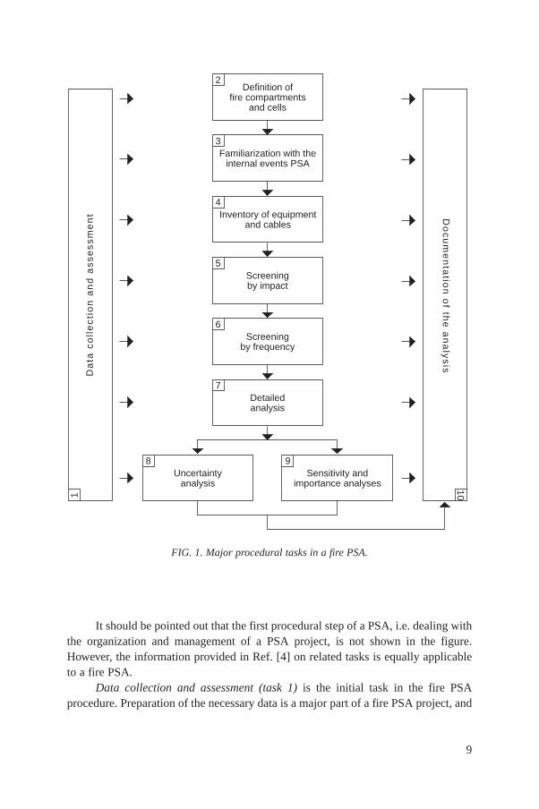
It should be pointed out that the first procedural step of a PSA, i.e. dealing withthe organization and management of a PSA project, is not shown in the figure.However, the information provided in Ref. [4] on related tasks is equally applicableto a fire PSA.
Data collection and assessment (task 1) is the initial task in the fire PSAprocedure. Preparation of the necessary data is a major part of a fire PSA project, and
9
FIG. 1. Major procedural tasks in a fire PSA.
7Detailedanalysis
9Sensitivity and
importance analyses
8Uncertainty
analysis
6Screening
by frequency
1
Da
ta c
oll
ec
tio
n a
nd
as
se
ss
me
nt
10
Do
cu
me
nta
tion
of th
e a
na
lys
is2
Definition offire compartments
and cells
3Familiarization with the
internal events PSA
4Inventory of equipment
and cables
5Screeningby impact

is a very time consuming task. It concentrates on collection of the plant specific datarequired for fire risk modelling; however, some data used in the internal events PSAmodel also have to be re-assessed to account for fire induced conditions.
This task begins at the early stage of a fire PSA and continues for almost theentire duration of the project. Data collection is a plant location oriented process thatproceeds in parallel with task 2, which deals with subdivision of the plant area intoindividual fire locations (fire compartments and cells).
It should be noted that detailed information is not needed for all plant locations.Most of the data are required for the analysis of compartments when moresophisticated models are introduced (typically those that involve higher risk).Therefore, the data collection process needs to be well co-ordinated with theanalytical tasks in order to avoid the collection and assessment of data that areunnecessary for the analysis. The screening analysis can be conducted with a smalleramount of plant specific information, which can be extended at the later stages ofmodelling as the preliminary results are obtained, and as the models require.
Definition of fire compartments and cells (task 2) is established at the initialstage of analysis. It is aimed at the division of all plant buildings and structures intodistinct fire compartments and cells3, which are scrutinized individually at the laterstages of analysis. All plant buildings and structures are systematically examined.Some plant locations that do not contain any plant equipment (e.g. administrativebuildings and offices) can be eliminated from further consideration at the very earlystage of analysis on the basis of qualitative judgement. However, prior to eliminationit has to be shown that a fire in one of these zones cannot spread to anadjacent zone that houses safety related equipment. Further elimination is carried outlater on the basis of more formal screening procedures. Sometimes, redefinition of thefire compartments and cells is needed at the later stages of analysis, when moresophisticated models are introduced. The results of this task include a set of firecompartment and cell drawings and specification of all the surrounding boundaries.
Familiarization with the internal events PSA (task 3) is an important task in thatit establishes a link between the existing internal events PSA models and the firerelated models. It starts with examination of the internal events logic models (e.g.fault trees and event trees), and their applicability to fire risk modelling. Sometimes,these models have to be extended in order to achieve the required level of detail andcompleteness. This task also identifies those plant systems and equipment, and all the
10
3 A definition of fire compartments and cells is provided in Safety Series No. 50-SG-D2(Rev.1) [3]. The terms fire compartment and fire cell are essentially analogous to the fire areaand fire zone terms used in codes, standards and guidance documents in the United States ofAmerica.
related elements of the model, that are important to fire PSA. Identification of all therelated cables and circuits is an integral part of this examination.
As a result of this task, a logic model suitable for calculating the conditionalunavailability of the required safety functions (task 6) is made available. Anotheroutcome is a list of the PSA related equipment and cables.4 Basic, component specificinformation is usually collected for certain PSA related items (e.g. for the requiredcomponent functions, and the electrical and control supplies). This information maybe further extended at the later stages of analysis.
The next task (task 4) is preparation of an inventory of equipment and cables(as identified in task 3). A list of PSA related items is prepared for each firecompartment and cell (defined in task 2). A plant walkdown is important in order toestablish correct localization of the equipment and cables in the fire compartmentsand cells. During the initial stages of the screening analysis, listing components byplant fire compartment or cell is sufficient. At the later stages of detailed analysis itwill be necessary to determine more accurately the component locations within thefire compartment or cell.
Screening by impact (task 5) is aimed at eliminating non-essential fire scenarioson the basis of impact oriented criteria (mostly, but not exclusively, qualitative). Itstarts with definition of the critical fire locations, followed by definition of thepossible single and multicompartment fire scenarios. The impact oriented criteriaused for screening out the individual fire scenarios take into account thecharacteristics of those fire compartments that are involved in the scenarioconsidered. The result of this task is a list of fire scenarios that can be significantcontributors to risk.
Screening by frequency (task 6) is aimed at the further elimination of those firescenarios that are retained after the first stage of screening (task 5). Screening isperformed on the basis of a simple, conservative estimate of damage frequency (e.g.core damage frequency). The conditional unavailability of the required safetyfunctions (e.g. safe shutdown) because of a fire is calculated from the existing internalevents PSA model. Conservative assumptions are made of the effect of a fire onequipment, and the related human actions. As a result, the number of risk significantfire scenarios is further reduced. For each of the remaining fire scenarios, aquantitative PSA model is available for further analysis.
11
4 The term PSA related equipment is systematically used in this report to describe allthe items credited in the internal events PSA model. For a PSA that is limited to in-coreradioactive releases, this term is equivalent to the term safe shutdown equipment, as outlinedin Section 3.3.3. In a PSA that considers other sources of radioactive release, the PSA relatedequipment also includes those items that are related to the safety functions which need to beperformed in order to prevent releases from ex-core radioactive sources, including thenecessary support features.

The detailed analysis (task 7) is aimed at reducing the level of conservatism inthe fire scenarios identified in task 6. The effect of intracompartment barriers andother fire protection measures, the location of equipment in the fire compartment orcell and other factors are taken into account. More realistic models are applied forassessing human actions, fire propagation, the effects of a fire on the equipment andcables, etc.
The analyst may select any of the above mentioned approaches (one or severalat a time) to revise the risk estimates calculated in task 6 for each of the risksignificant fire scenarios. More fire scenarios are screened out in the course of thisprocess, and refined risk estimates determined for the remaining scenarios.
The uncertainty analysis (task 8) is aimed at identifying the sources ofuncertainty, and their evaluation. Qualitative and quantitative assessments are carriedout. Quantifiable uncertainties are investigated through formal uncertainty analysesusing the fire risk model developed in tasks 6 and 7.
Sensitivity and importance analyses (task 9) are aimed at identifying the risksignificant elements of the fire PSA model. Sensitivity studies are performed for theimportant assumptions, and the relative importance of various contributors to thecalculated results determined. The fire risk model developed in tasks 6 and 7 is usedin this task.
Documentation of the analysis (task 10) is one of the tasks that continues foralmost the entire duration of a PSA project. The results of analysis of each task arethoroughly documented and the final documentation is prepared. The results of thePSA are displayed and interpreted in line with the objectives of the PSA.
3. PREPARATION PHASE (TASKS 1–4)
3.1. DATA COLLECTION AND ASSESSMENT (TASK 1)
A fire PSA relies on the availability of plant information (both qualitative andquantitative). As previously mentioned, data collection is a major, time consumingtask that extends over several analytical tasks of a fire PSA. Two major types of plantspecific data are obtained: internal events PSA related data and fire related data.
The fire PSA is strongly dependent on the internal events PSA. A large portionof the model is retained and used in the fire PSA, but a number of aspects will haveto be reviewed, and in some cases developed. The information that needs to begathered for the fire PSA can be categorized as a list of initiating events; the PSAlogic models; the basic events of the model; and human actions.
12
Fire related data require a considerable amount of plant specific information.These data can be classified into the following major groups: the physicalcharacteristics of the fire compartments, and their inventory; fire occurrence data;reliability estimates of the fire detection and suppression systems; human actions andhuman error probabilities; and fire induced equipment failure modes and damagecriteria.
The first group may be available from a fire hazard analysis based on thedeterministic approach (as described in Ref. [1]), which typically is performed for theplant prior to a fire PSA. This group of data includes the following categories: thesafety system inventory; the fire compartment inventory; the combustibles inventory;the ignition sources inventory; the passive fire protection features; the fire detectionand alarm systems; the fire extinguishing systems; the emergency lighting; thecommunication systems; the smoke and heat removal systems; and the manual firefighting arrangements. Detailed specification of the scope of these categories can befound in Ref. [1].
The required plant specific information can be acquired from various designsources, as well as from plant walkdowns, where in situ information is gathered andverified.
Collating design information from plant documentation is usually the firstphase of data collection. The recommended sources of plant specific informationinclude a description of the systems, equipment lists, design drawings, plantprocedures and other similar items. Several types of drawings should be mentioned inthis context:
(1) General arrangement drawings that display the current configuration of plantareas and the location of major equipment;
(2) Fire barrier drawings that show the fire compartment walls and the location offire doors;
(3) Piping and instrumentation diagrams for the relevant systems;(4) Electrical distribution drawings and electrical logic diagrams;(5) Electrical drawings that show the connection of the power and control circuits
for the systems, the arrangement of the motor control centres, and the cable andconduit routing;
(6) Ventilation path drawings.
All the information obtained from plant documentation has to be verified byvisually inspecting each fire compartment throughout the entire plant. This isessential in order to ensure that the data represent the actual and current condition ofthe plant.
It should be noted that a plant walkdown also plays a very important role infamiliarizing the analyst with the fire specific features of the plant. The purpose of
13

such a walkdown is to determine or verify the equipment locations and to gatherinformation on the physical condition of the compartment or cell, and on the firerelated features, some of which may not be easily identified from other data sources(e.g. the nature of the openings in the fire barriers or the existence of louvres oncabinets).
Several plant walkdowns are necessary during different phases of the study. Aplant familiarization walkdown is usually performed during the initial stages ofanalysis. A second, detailed walkdown may be performed when the screeninganalysis is nearing completion in order to confirm the information used and to gatherdata on those specific compartments that will require detailed analysis. Additionalwalkdowns, confined to compartments undergoing detailed analysis, may be requiredto confirm and collect additional data, and to examine corrective actions with a viewto reducing potential vulnerabilities, if required (task 7).
Plant specific fire occurrence data are collected for the source of ignition, thematerials involved in the fire, and the damage to equipment and cables. It is advisablethat, in addition to the fire events, the analyst collects generic data on the fireinitiation frequencies which are available in the literature and which are drawn fromnuclear power plant operating experience. Sources of such data include Refs [7–11].
Reliability data for the fire protection features include data for active fireprotection equipment (fire detection and fire extinguishing systems) and forintercompartment fire barriers (dampers, doors, curtains, penetration seals, etc.).These data can be derived from plant operational experience (event records, test andmaintenance records, etc.) or, using the available plant specific data, extrapolatedfrom generic sources of information.
Plant operating procedures, particularly those concerned with operator actionsfollowing indication of a fire or other initiating event, form the basis of the operatoractions that can be included in the fire PSA. A number of the operator actions in theinternal events PSA model, including certain important recovery actions, will haveto be reviewed and, in some cases, requantified. This is discussed further inSections 3.3.4 and 5.4.
Where an action local to a plant is required it is necessary to consider all thosefactors that may prevent plant personnel from carrying out this action, e.g. theunavailability of emergency lighting. The routes within the plant by which access isachieved have to be determined. The fire situation may involve the normal or themost direct route, but it will be necessary to identify and consider a viable alternative.Walkdowns play an important role in gathering and verifying information of thistype.
In some cases, a walkdown may determine that credit should not be taken forany operator actions within a fire compartment until well after the fire has beensuppressed. This would be true, for example, if the action required that the operatortraverse a significant portion of the compartment, perform complicated or multiple
14

control actions, or remain in the compartment for any significant fraction of time.Such actions should also not be credited in scenarios involving larger fires.
The fire analyst will need to gain knowledge of the susceptibility of varioustypes of equipment to the different phenomena that may be experienced in a fireevent. The analyst will also have to establish a list of equipment types within theplant, and to specify their damage mechanisms (e.g. heat, flame, smoke and water)and failure modes. For example, passive components, such as pipes, check valves andmanual valves, are generally not expected to fail in a fire. A motor (e.g. for a pump)may fail from heat but not from exposure to smoke, while an electronic device mayfail from heat and smoke.
Since this data collection process produces a significant amount of interrelateddata it is recommended that the information be arranged in a systematic way (e.g.tables), preferably in a computerized database. This greatly facilitates the retrievaland processing of data. It is advisable that comprehensive and well organized datasheets be used during plant walkdowns. Some examples of such data sheets can befound in Refs [1, 10, 12].
Care in the use of generic data should always be exercised. For example,regarding fire occurrence frequencies, definition of a recorded fire will vary and beinfluenced by the fire detection and suppression measures taken. This applies also toequipment failure rate data.
Even under the best of circumstances some gaps in the information base willremain unfilled; this issue is discussed further in Section 6.7. It is important for theanalyst to recognize and acknowledge where such information gaps have occurred,and to describe in the analysis how these gaps were overcome.
3.2. DEFINITION OF FIRE COMPARTMENTS AND CELLS (TASK 2)
The division of all plant buildings and structures into distinct fire locations (firecompartments and cells), which are scrutinized individually at the later stages ofanalysis, is an important task that permits systematic and definable evaluation of fireevents.
Physical separation between safety relevant systems and equipment is aneffective fire safety feature. Such separation can be achieved through distinct firecompartments, which are plant areas completely surrounded by fire barriers.5 The firecompartments are designed to prevent the spread of the effects of a fire to or fromother plant compartments. The fire resistance (fire rating) of the compartment barriers
15
5 A definition of fire barriers and fire barrier rating is provided in Safety SeriesNo. 50-SG-D2 (Rev. 1) [3].

may be sufficient to contain fires initiated in that compartment (design approachbased on fire containment), or may require additional fire protection measures to limitfire spread (fire influence approach).
Formal definition of the fire compartments and the fire resistance rating of therelated barriers may not be readily available for the PSA. In such cases it will benecessary to undertake a review of the major construction elements of the plant inorder to derive the appropriate fire compartments and the fire rating of barriers.Guidance is given in Ref. [1].
Some flexibility should be exercised by the analyst in defining firecompartments for PSA use. For instance, the analyst may prefer to consider severalfire compartments as one compartment, if this facilitates the analysis. It is stronglyadvisable to avoid unnecessary division of the plant into a large number of smalllocations, at least at the early stage of analysis.
The fire resistance rating of the walls and ceilings may be determinedanalytically or be evaluated by engineering judgement according to simplified stateof the art methods that involve the thickness and material of the wall (such as graphsor tables published in the literature).
Fire barrier elements, e.g. doors or dampers that are installed in the walls, areincluded in this process. The fire resistance rating of each fire compartment barrier isdetermined by the weakest (lowest fire rated) element of that barrier.
Where a fire rating cannot be established and justified, the barrier cannot beconsidered as being fire rated, and it is necessary to consider larger areas of the plantas a single fire compartment. In such a situation, the fire compartment may besubdivided along logical lines such as rooms, functional areas or areas with clearlydefined spatial separation. Such areas are called the fire cells of the fire compartment.Some examples of the definition of fire compartments and cells in a nuclear powerplant can be found in Ref. [3].
Typically, a set of fire compartment and cell drawings, and specification ofall the surrounding boundaries, are generated in this task. Use of a comprehensive andflexible numbering system for fire compartment and cell identification is advisable;numbers are usually assigned to the fire compartments after the first stage ofscreening.
3.3. FAMILIARIZATION WITH THE INTERNAL EVENTS PSA (TASK 3)
A fire PSA can only be conducted if some form of plant model exists thatlogically examines contributions to core damage, plant damage states, etc.
This task covers examination and interpretation of the existing internal eventsPSA (or its equivalent) to determine the plant systems and equipment, as well as allthose related elements of the model that are important to the fire PSA. Section 3.3.1
16
discusses the general requirements that should be fulfilled to make an internal eventsPSA suitable for fire risk assessment. A number of issues specific to fires also haveto be considered; these are discussed in Sections 3.3.2 to 3.3.6.
3.3.1. Requirements of the internal events PSA
A fire PSA is normally performed either as an integral (later) part of a full scopePSA or as a discrete task following completion of an internal events PSA. Tominimize potential errors or misuse of the PSA results, the objectives, limitations andassumptions used in the internal events PSA should be understood.
The unavailability of an internal events PSA creates a number of difficulties forfire PSA in terms of a full representation of the logical safety features of the plant.Without such models it will not be possible to estimate the relative importance of firesin a quantitative manner, and thereby provide results for informed decision making.
The information given below assumes that an internal events PSA model existsand that it is comprehensive. A comprehensive model should comply with theguidance given in Ref. [4]. Where such a PSA model is not available, the analyst maybe able to adapt or tailor existing logic models to meet the minimum intent below.
The extent of the internal events PSA will also influence selection of thescreening criteria to be used in task 6, depending on whether the core damagefrequency, plant damage states or other ex-core releases of radioactivity are considered.
The internal events PSA is used to provide information on the initiating events6
and systems (including support systems) that are used in the mitigation of such events.The internal events PSA should contain information on the possible causes of
initiating events, as well as details of those initiating events that have been groupedin a particular event tree model and those that have not been modelled because ofsome form of qualitative screening. A review of initiating events is given inSection 3.3.2.
The internal events PSA should also contain information on those systems andcomponents whose failure to function correctly in response to an initiating event maylead to an undesired consequence. Such equipment includes safety related frontlineand support systems, and non-safety related systems such as main feedwater and off-site power. For a fire PSA, information relating to those components that use orprovide an external power source (electric, pneumatic, hydraulic) is required.
A comprehensive internal events PSA should already include the failure modesof interest in the fire PSA for such components. The required detail, and its use, aredescribed in Ref. [4].
17
6 In the context of these guidelines only, the following definition of an initiating eventis applied and taken to be exclusive: An initiating event is a change in the hardware state of anyequipment that leads to a perturbation in the normal heat production–removal balance of the plant.

In this context it is expected that the internal events PSA will be developed tothe component level in order to identify explicitly those items that provide the safetyfunctions required to mitigate an internal initiating event (Section 3.3.2). Theseinclude: the pumps; the motor, with pneumatically or hydraulically operatedvalves; electrical supply equipment, including transformers and breakers;instrumentation and control (I&C) signals and related hardware; and pipework andstructures.
Typically, this involves systems that provide the following safety functions:control of reactivity; controlled removal of the core decay heat and stored heat;maintenance of the integrity of the reactor coolant boundary (pressure control);maintenance of the reactor coolant inventory; protection of containment integrity(isolation, overpressure); and scrubbing of radioactive materials from thecontainment atmosphere.
If the available logic models do not provide this level of information, theanalyst, with extreme diligence and care, may be able to meet the intent of the PSAmodel. However, such an approach must be adopted with this provision in mind andin recognition of the potential problems that may arise in the quality and usefulnessof the final product.
3.3.2. Review of initiating events
This task determines the list of components used or implied in the PSA in termsof their potential, as a result of a fire, to cause an initiating event that requires someform of control or mitigating action, either manual or automatic.
This task starts with a review of the initiating events considered in the PSA. Anumber of techniques for identifying the initiating events of an internal events PSAare described in Safety Series No. 50-P-4 [4]. In turn, each initiating event has to bereviewed in order to determine whether it can be induced by a fire.
It should be recognized that such effects include failure of the power supply tothe equipment from the main electrical bus(es) and actuation signals for equipmentoperation (e.g. start, stop, open, close) from the control room and the control relaycabinets. In terms of completeness, the analysis could also be extended to coveridentification of those instrument sensors and signals, including any processing, thatmay adversely affect operation of the equipment.
The initiating events identified should be the same as those already included inthe internal events PSA. However, based on low probability, some analysts may havechosen to exclude certain initiating events from the internal events PSA. In suchcases, the fire PSA analyst must bear in mind that the fire may cause more severefaults than those considered or modelled previously, thus necessitating the creation ofa new event sequence model for evaluation or allocation to an equivalent boundinginitiating event.
18
An example of this is the possibility that the fire may lead to multiple openingof the steam generator power operated relief valves, whereas the internal eventsmodel may be limited to spurious opening of a single relief valve. Also of concern ismultiple loss of the electric power supply to the safety related components. In suchcases, either a new logic model for the multiple event will have to be prepared, or thefire PSA analysis may have to adopt a representative (but conservative) equivalentevent such as a steam line rupture of the steam generator in the first instance.
It is important to note that the review of potential fire initiating events shouldalso include the support system effects on those systems that are involved in thenormal operation of the reactor.
The initiating events that arise from this review can generally be categorized asone of the following:
(1) Events leading to controlled reactor shutdown;(2) A reactor trip (scram) initiated by the operator;(3) Transients leading to an automatic scram, e.g. tripping of the turbine, loss of
feed, loss of the electric power supply, loss of off-site power, opening of a steamgenerator relief valve;
(4) LOCA from the primary circuit, e.g. failure of a pump seal (because of loss ofseal cooling), opening of a pressurizer relief valve, interfacing system LOCA;
(5) Events resulting in releases of ex-core radioactivity.
The level of work involved in this task varies according to the level ofinformation already included in the PSA modelling. It is important to take intoaccount all those items of equipment that can influence the PSA modelled function.This will necessarily extend the analysis to a detailed understanding of the operationof the system or subsystem in terms of motive, and the control power cables andsignals that operate the system.
3.3.3. Identification of the PSA related systems and equipment
This task determines the list of those components that are credited in theinternal events PSA in terms of their use in the control or mitigation of a fire causedby an initiating event (the term PSA related equipment is systematically used in thisreport to describe these components). In the case of a PSA that is limited to in-coreradioactive releases, this list relates to the frontline and support systems that providesafe shutdown of the reactor and adequate heat removal from the reactor core (safeshutdown equipment); it includes alternative and dedicated systems. In a PSA thatconsiders other sources of radioactive release, the list includes also those items thatare related to the safety functions which need to be performed in order to preventreleases from ex-core radioactive sources. However, it does not include fire protection
19
20
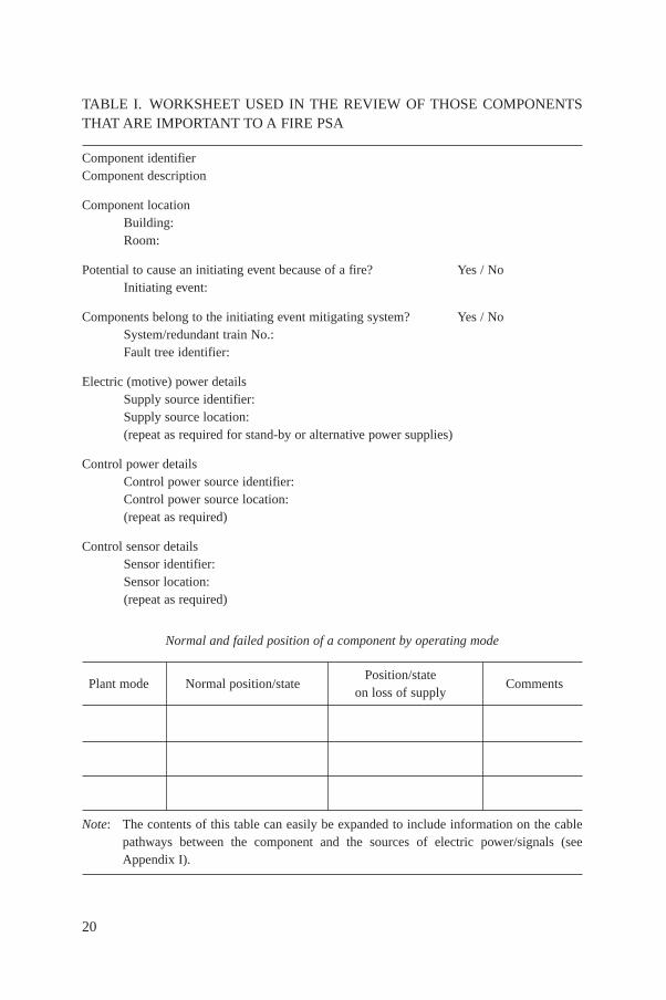
TABLE I. WORKSHEET USED IN THE REVIEW OF THOSE COMPONENTSTHAT ARE IMPORTANT TO A FIRE PSA
Component identifierComponent description
Component locationBuilding:Room:
Potential to cause an initiating event because of a fire? Yes / NoInitiating event:
Components belong to the initiating event mitigating system? Yes / NoSystem/redundant train No.:Fault tree identifier:
Electric (motive) power detailsSupply source identifier:Supply source location:(repeat as required for stand-by or alternative power supplies)
Control power detailsControl power source identifier:Control power source location:(repeat as required)
Control sensor detailsSensor identifier:Sensor location:(repeat as required)
Normal and failed position of a component by operating mode
Plant mode Normal position/statePosition/state
Commentson loss of supply
Note: The contents of this table can easily be expanded to include information on the cable pathways between the component and the sources of electric power/signals (see Appendix I).
systems, which are considered separately as an element of the fire propagation model(Section 5.5).
For each initiating event that has the potential to be caused by a fire event, asdiscussed in Section 3.3.2, it is necessary to determine the systems credited in thePSA with controlling and mitigating the effects of that initiating event. This is achievedin the first instance by inspection of the PSA logic models (event and/or fault trees).In turn, a list is developed of the equipment that provides the required safety function.Appendix I gives an example of the items to be listed, and the additional informationrequired beyond that which may be included in the internal events PSA.
In deriving such information it is not sufficient to rely solely on a fire hazardanalysis (e.g. Ref. [1]), since the PSA may include non-safety related systems, e.g.main feedwater systems and ‘normal’ electrical supplies.
It is useful and recommended that the list of equipment derived from a reviewof the PSA, and expanded where necessary to include complete information on theelectric power and control supplies, be incorporated into a fire PSA database, whichis then further extended in task 4. Table I illustrates the type and organization ofcomponent related data.
3.3.4. Identification of the human error contribution
This subtask determines the list of operator actions in the internal events PSAfor which estimates of the probability of human error may differ as a result of a fire.It also provides guidance on the error probabilities to be used in the screening stagesof the fire PSA.
Human actions are typically an integral part of event sequences in an internalevents PSA. The failure probabilities for these human actions are evaluated as part ofan internal events PSA effort, assuming a normal working environment. The samehuman actions may be addressed in modelling the impact of a fire on plant safety.However, the failure probabilities may have to be adjusted to take into account theunusual environmental conditions (e.g. smoke) imposed by the fire event.
The internal events PSA model normally includes a number of operator actionsthat contribute to the unavailability of systems. The actions are generally of twotypes: (a) those that occur prior to the occurrence of the initiating event, and (b) thosethat are required to be performed after the occurrence of the initiating event.
Failure to reinstate power supplies to a motor operated valve followingmaintenance is an action of type (a). Failure to recognize the need for a particularaction (cognitive error) or failure to perform a particular action within a giventimeframe (error of omission) is an action of type (b).
Values for the human error probabilities (HEPs) relating to the unavailabilityof components prior to the occurrence of fire initiating event (a) will not requirere-evaluation. The HEP values assigned to actions of type (b) in the internal events
21
PSA are determined for particular conditions associated with the initiating event,and thus may not be applicable to the fire case. There may also be post-fire operatoractions that the internal events PSA does not model; these have to be addressed inthe fire PSA.
The actions required in response to a fire event may involve physical andpsychological conditions that differ from those in internal events modelling,particularly for those actions that are undertaken outside the control room. Forexample, because of the fire effects on equipment and access routes, these actionsmay take longer than originally specified. For this reason it is recommended, at thisstage, that each post-fault HEP be set to 1.0 to ensure that the fire related influencesare not omitted from the screening analysis. Task 7 describes revision of the HEPvalues in cases where this assumption leads to unacceptably high consequences. Itmay be one of the first steps considered in undertaking detailed analysis (task 7).
Historically, one issue that has not been widely modelled is errors ofcommission in response to a fire (as defined in Ref. [4]). Indeed, the internal eventsPSA may not have explicitly modelled such errors. For this reason it is not possiblein this report to provide specific guidance on this developing issue. However, itshould be recognized that the probability of these errors may increase after a fire. Thedecision to include these errors currently remains with the analyst or with specificrequirements on the scope of the fire PSA.
3.3.5. Identification of the PSA related cables
For the components identified in Section 3.3.3 it is necessary to determinewhich cables and circuits are required so that each particular component can performits safety related function. The following circuits should be analysed: the motivepower supply circuits, the control power supply circuits, and the instrumentation andcontrol circuits.
Electric motive power supply circuits provide the power for operating electricallydriven components (motors and valves). The control power supply circuits providethe electric power to I&C equipment; in turn, this equipment provides signals fromthe plant for processing, and also to the plant for the remote control of components.Process monitoring and component control are the main functions performed by I&C.Component control also includes permissive and/or interlock functions, i.e. to permit(or prevent) operation of the component when either a required condition exists or acertain signal is required.
All these functions can be provided by a dedicated electrical circuit or byelectronic signals. The information can be transmitted in analog, digital or processeddigital (multiplexed) form using electrical or fibre optic cables.
Each cable should be evaluated to determine the effect of its failure on theoperation of the required PSA related components. It is important that all possible
22
failures are identified. The following failure modes, or a combination thereof, shouldbe considered for cables:
(1) Open circuit: A circuit failure that causes loss of the electrical continuity of aconductor or loss of the transmitting capability of a fibre optic cable.
(2) Short to ground: A circuit failure that results in the cable conductors becomingconnected to a grounded item (e.g. cable tray).
(3) Short circuit: A circuit failure that results in the cable conductors coming intocontact with each other.
(4) Hot short: A short circuit failure in which a de-energized conductor comes intocontact with an energized conductor such that the de-energized circuit becomesenergized. Two types of hot short should be distinguished:
(a) An intracable hot short, for conductor to conductor shorts within amulticonductor cable;
(b) An intercable hot short, for a non-energized cable that comes into contactwith a separate energized cable.
The most likely fault mode for a single conductor cable is a short to ground.Failures of this type can lead to deactivation of the electrical circuits, either bytripping a circuit breaker, causing a fuse to open, or by melting open the wire or cable.In control circuits this fault leads to loss of the control function; in instrument circuits,this fault causes either a loss of signal or a false signal at the high or low end of therange, depending on the circuit. An open circuit fault generally occurs because ofcollapse of the cable support structure, failure of the circuit protection devices to tripin the event of a sustained short to ground, or prolonged severe fire exposures. Thesetwo types of fault (short to ground and open circuit) can be treated similarly in termsof their anticipated system impact in the fire PSA.
For a multiconductor cable, the most likely initial fault mode is an intracablehot short, i.e. conductor to conductor faults within the cable. Faults of this type cansimulate the actions of a manual control circuit switch, circuit breaker or solenoidswitch. This might lead to undesirable effects, such as the reconfiguration of valvesin an operating system and the opening of solenoid operated safety relief valves, e.g.on the pressurizer of a PWR, or to actuation of an inactive system. These faults canalso lead to false readings on a sensor circuit. In the longer term, multiconductorcables are expected to short to ground as the fire damage progresses. The timing ofthis transition from an intracable hot short to a short to ground remains a point ofuncertainty. In severe fire exposures, rapid transition is anticipated (within minutes oreven seconds). In more moderate exposures, or when rapid intervention of severe fireexposure is postulated, a sustained intracable hot short is possible. The impact of bothshort term and sustained intracable hot shorts in multiconductor cables should beconsidered in the analysis, especially for the control cables.
23
Intercable hot shorts can occur in any system that includes energized powercables. Faults of this type can lead to actuation of the non-energized circuits, or toapplication of destructive voltages to lower voltage systems. The likelihood andduration of such intercable hot shorts also remain areas of uncertainty and debate.Depending on the plant and the fire scenarios, this may lead to serious initiatingevents or to additional contributors to system unavailability, and should not beoverlooked.
To properly reflect this potential it is recommended that all the remotelyoperated PSA related components, particularly valves, be reviewed for potentialproblems from spurious actuation as a result of short circuit or hot short failures. Thelisted information (database) should include the normal or expected position of thevalve and the worst case position as a result of the fire. This will necessarily involvea review of the control and operation of the valve.
It should be noted that fire induced failures in the process monitoring I&C donot directly affect operation of the required equipment, but may prevent the operatorfrom taking the appropriate action associated with the required safety functions. ThePSA analyst may decide to model such appropriate effects directly, or to include themin the modelling of human actions.
The following observations are made regarding analysis of the spuriousactuation of electrical or I&C circuits.
Credit is not taken for the proper functioning of any electrical or I&C circuitthat has not been completely analysed. For example, automatic signals that positioncomponents to the states required for safe plant shutdown are not taken into accountunless it has been demonstrated that the fire will not affect those circuits that generatethe automatic signals.
Where permissive or interlock functions (based on analog or digital technology)are used to control the PSA related equipment, all the cables associated withinterlocking functions are included in the spurious analysis.
It is important that the analysis also addresses fire damage to those circuits andcables that are not directly related to the successful operation of PSA relatedcomponents but may indirectly affect the operability of the required systems. A moredetailed discussion of this problem is given in Section 3.3.6.
3.3.6. Identification of the associated circuits of concern
Components and cables of PSA related systems may share certain physical orelectrical characteristics with non-essential systems (i.e. those not considered in theinternal events PSA). Because of this interrelation, fire induced damage to non-essentialsystems can, in certain cases, negatively affect the operability of PSA relatedequipment. Associated systems of concern include any circuit whose fire induceddamage could prevent operation or cause malfunctioning of the PSA related equipment.
24

The common power supply and common enclosure are the most importantinterrelation factors that should be evaluated in identifying the associated systems ofconcern.
Several possible failure modes have been identified for PSA related circuits thatshare a common power supply with non-essential circuits. These failures involve thepossibility of low or high impedance shorting [12, 13], creating conditions that maynot be covered or bounded by the failure modes considered in Section 3.3.5. Examplesituations are described in Appendix II.
Other non-essential circuits of concern are those associated through commonenclosure (conduit, tray, junction box, panel, etc.). Two failure mechanisms arepossible in this case: the physical propagation of a fire outside the immediate area,and the secondary ignition of essential cables under overcurrent conditions caused bythe effects of a fire [12]. More detailed information is provided in Appendix II.
If the particular plant design is known or believed to be sensitive to suchinteractions, then the fire PSA may need to be expanded in order to ensure that thepotential is properly assessed. The analyst should investigate all those factors thatmay affect the propagation of the above mentioned faults, such as the characteristicsof the protective devices and cables, the protection of non-essential cables of concern(e.g. fire barrier wraps, physical separation), and the existence of written procedures(e.g. to shed non-essential plant loads from potentially affected power supplies). Inprinciple, this task is part of the fire hazard analysis.
3.4. INVENTORY EQUIPMENT AND CABLES (TASK 4)
In this task, the location of components and the routing of cables, as identifiedin task 3 (Section 3.3), are specified. It should be noted that relevant components andcables include those that, when affected by a fire, may induce an initiated event, aswell as those that are relevant to its mitigation. Basic design information for all thePSA related items gathered in PSA familiarization (task 3) is organized anddocumented.
It is advisable that this information includes indentification of the component(identification number, system, train, basic event identifier); location of thecomponent (building, elevation, compartment, cell); a brief description of the motoroperated valve, charging pump and cable; function of the component and its positionduring normal operation and reactor shutdown (e.g. open, closed, on, off, energized,de-energized); the power supply; the control power; and the signals. The worksheetshown in Table I is an example of the format applicable to this task.
For cables, the information needs to be extended to include identification of thecomponents to which the cables are connected, identification of the tray to whichthey belong, and the position of the tray in the compartment. Some of this information
25
may be difficult to obtain, or may not be needed to complete initial screeninganalyses. Gathering information on cable end points is important and should not bedeferred until detailed analysis is performed. For further evaluation it may also beuseful to specify which cables are already fire rated or protected by fire resistantcoatings and fire rated wraps.
Where a deterministic fire hazard analysis has been performed, a list of theequipment expected to be damaged by a fire in each plant fire compartment can beobtained with relative ease. However, these deterministic studies usually do notidentify all the accident mitigating equipment that is typically modelled in the internalevents PSA model. This equipment may include components associated with the off-site power, feedwater, condensate and containment functions, and has to be identifiedon an ‘as needed basis’ in order to demonstrate that the screening criteria have beenmet, or to perform realistic detailed analyses in a later task.
It is essential that the method used to identify and locate the requiredcomponents, as well as the instruments applied to achieve a given shutdown function,complies with that adopted in the plant’s deterministic hazard analysis study. If suchan analysis has not been performed it is necessary to collect the required data fromthe available plant documentation, in combination with plant walkdowns. Guidancefor performing such activities is given in Ref. [1].
In all cases, this information is verified by performing plant walkdownsthroughout the plant to review whether or not the collected data are actually supportedby the physical conditions that exist in the plant. Some specialized methods such assignal injection techniques can be applied, if required, in addition to visual inspectionto trace the actual cable routing.
4. SCREENING PHASE (TASKS 5 AND 6)
4.1. SCREENING BY IMPACT (TASK 5)
4.1.1. Overview
Screening by impact is the first stage of a systematic screening analysis whichfocuses on defining those fire scenarios that may be significant risk contributors.
Selection of potentially significant fire scenarios is made using very simpleimpact based screening criteria. Several factors, both qualitative and quantitative, aretaken into account at this stage of the screening process, including the existence of
26

safety relevant (PSA related) equipment and cables in the compartments consideredin a fire scenario, the compartment fire loads and the effectiveness of the barriersbetween the fire compartments.
At this stage of evaluation, all the equipment and cables exposed to the fire areassumed to have failed, i.e. the assumption is made that the detection devices andextinguishing systems are ineffective; fire shields or coatings are not taken intoaccount.
Two fire damage situations are investigated: simple situations that involve fireinitiation and growth within a single compartment (single compartment fire damage),and fire damage situations that involve a fire in more than one compartment(multicompartment damage).
A fire compartment cannot be screened out if:
(1) After a fire event in the compartment there is a demand for safe shutdownfunctions because the plant cannot maintain normal operation, including therequirements of technical specification;
(2) The compartment contains PSA related accident mitigating components orcabling, including the associated essential support features7 (as outlined inSection 3.3.3).
4.1.2. Single compartment fires
In the first step of impact based screening all those single compartment firesthat may be significant risk contributors are identified.
A systematic evaluation is performed for all plant locations to identify thosewhich satisfy the screening criteria outlined in Section 4.1.1. At this stage of analysis,evaluation is usually limited to the fire compartment level; fire cells are used in amore detailed analysis carried out at the later stages of fire PSA.
A list of compartments that cannot be screened out is retained for subsequentscreening stages.
It should be noted that, for some fire compartments containing PSA relatedmitigating equipment, an unscheduled plant shutdown may not be necessary orenforced by technical specifications when a fire occurs in one of these compartments.Single compartment fires that involve such compartments are not potentiallysignificant risk contributors. However, such compartments should not be eliminated from further evaluation, since they may be involved in risk significantmulticompartment fires (Section 4.1.3).
27
7 This includes all those items related to the safety functions that have to be performedin order to prevent releases from in-core and ex-core radioactive sources (in the case where thePSA considers such releases).
4.1.3. Multicompartment fires
The objective of this step is to identify the potential risk significant fire damagesituations that involve more than one compartment. It is assumed that the fire mayspread from one compartment to another by way of the shared barriers or via theventilation ducts that link the compartments. In the latter case, the compartmentsinvolved in the fire scenario may not be adjacent to each other. In addition, the effectsof heat transfer through fire barriers are considered.
For each fire compartment retained for further evaluation, multicompartmentcomplexes are defined by adding to that compartment all the surroundingcompartments (in all directions) and all those compartments that share ventilationwith this compartment. Then all possible combinations of the compartments areinvestigated with regard to the spread of combustion products and/or the transfer ofheat to adjacent (or connected) compartments.
It is generally accepted that fire spread between more than two compartmentsis not considered. However, this assumption should not be applied automatically. Itshould be revised for multicompartment fires in which a fire starts in a compartmentwith a very high fire occurrence frequency, or for those scenarios that involvecompartments separated by barriers with a high failure probability (especially thosethat require an active response to maintain fire barrier integrity) and for thosecompartments with significant loadings of highly hazardous flammable materialssuch as liquid fuel storage tanks and oil filled transformers.
Two factors are considered in selecting significant multicompartment cases: thefire load in the compartment in which the fire starts, and the effectiveness of the firebarriers that separate the fire compartments involved in the fire scenario. These twoaspects are discussed in Sections 4.1.3.1 and 4.1.3.2, respectively. Guidance forscreening multicompartment fire damage situations is given in Section 4.1.3.3.
4.1.3.1. Compartment fire load
The compartment fire load [1] is estimated on the basis of a mass inventory ofall the combustibles inside the compartment, including any transient materialsestimated realistically for the compartment under plant operational conditions. Thefire load is calculated from the conservatively estimated mass of all the combustibles,and their specific combustion heat. The fire load density is defined as the totalcombustible energy per unit of compartment floor area.
On the basis of this parameter, a conservative estimate of the fire severity, e.g.the fire duration, can be made using standard time–temperature curves and/oranalytical calculations. This estimate can be used to evaluate the effectiveness of thebarriers that separate the compartments under consideration.
28
A compartment may be eliminated from the multicompartment damageanalysis if the fire load in that compartment is less than a prespecified threshold value.This value can be related to a fire severity that would not challenge the minimum fireresistance assigned to any of the fire compartment boundaries. It is essential that, incalculating the fire severity, account is taken of the ventilation regime in thecompartments.
4.1.3.2. Fire barriers
The effectiveness of a fire barrier in preventing the propagation of fire effectsto adjacent compartments is determined by the physical performance of the elementsof the barrier and the discrete effects associated with the transmission of fire effectsthrough an intact barrier.
All the boundaries (walls, floor and ceiling) of a fire compartment credited asfire barriers, and their associated elements, have to be evaluated carefully. Theelements of a boundary may include doors, ventilation dampers, shutters andpenetration seals.
It is essential that the fire resistance of these elements is confirmed, taking intoaccount the severity of the fire in the compartment under consideration. Incompartments designed according to the fire containment approach (as referred to inRef. [3]) it is generally accepted that the passive elements of the fire related barrierswill not be breached by a fire initiated within the compartment. However,confirmation is needed that there are no concentrations of combustible material inclose proximity to the fire barriers which may invalidate this intent, and that theelements have been properly maintained and remain fully intact.
In the case of fire cells designed according to the fire influence approach (seeRef. [3]), a passive barrier alone may not be sufficient to contain the effects of all thefires originating within the cell. At the screening process stage of the fire PSA, whenactive fire protection measures are not considered and credited, the assumption thatthe fire barriers are adequate may not be justified and should not be applied withoutadequate substantiation and confirmation by the analyst.
In both the fire containment and fire influence approach it is possible that thefire barrier is effective in its designated manner but that the fire effects in onecompartment may affect sensitive equipment in another, adjacent compartment, e.g.by heat transfer across a shared fire barrier. In particular, this is more applicable toolder plants designed according to earlier standards, where such sensitive equipment(e.g. electronic equipment or cabinets) may be located on or closely adjacent to a firebarrier.
In addition to the fire resistance qualification aspect, other possibilities ofbarrier failure have to be evaluated, including damper failures, doors left open, seal
29
failures and the existence of other openings. Particular attention should be given tothose barrier elements that require an active response to maintain fire barrier integrity.
A fire spreading between two compartments is screened out at this stage if thecompartments are separated by qualified and reliable barriers (e.g. a concrete wallwith no openings). If any of the above mentioned failures are likely to occur, thescenario is retained for further analysis. It should be noted that definition of aqualified and reliable barrier may depend, to some extent, on the analyst. It may alsobe country specific because of the existence of specific requirements or regulations.
4.1.3.3. Screening
The screening criteria defined in Sections 4.1.3.1 and 4.1.3.2 are applied toeach multicompartment complex. A list of those complexes that do not satisfy thecriteria is created for use in the later stages of screening.
4.2. SCREENING BY FREQUENCY (TASK 6)
The compartments and multicompartment complexes that could not bescreened out in the preceding task may be subjected to frequency based screening.The frequency of core damage can be used for this purpose.8 It can be expressed as:
Fcore damage = Fdamage × CCDP
where CCDP is the conditional core damage probability determined using the internalevents PSA logic model (Section 4.2.3), and Fdamage is the frequency of fireoccurrence and eventual damage to the equipment and cables.
In this step it is still assumed that a fire event affects all the equipment andcables within the compartment or multicompartment complex, and leads to theirdamage. Also, since this is a screening step, for single compartment cases, Fdamage istaken to be the fire initiation frequency of the compartment, and formulticompartment complexes, Fdamage is taken to be:
Fdamage = Ffire initiation × Pbarrier failure
where Pbarrier failure is the probability of failure of the barriers between compartmentsthat leads to a multicompartment fire situation.
30
8 For fire damage situations that involve ex-core radioactive sources, the term coredamage should be replaced by the more general term plant damage, which includes otherundesirable plant end states that are related to ex-core radioactive releases.

4.2.1. Frequency of a fire occurrence in a compartment
Fire occurrence frequencies are established for each of the fire locations. Theseestimates are usually derived on the basis of generic data and specific information onthe fire location. Where reliable fire frequency data are available, particularly forolder plants or plants with older sister stations, this should be strongly preferred togeneric data. However, care needs to be taken when using plant records, particularlythose that go back over many years. Plant design, protection or operation may havechanged such that some events are no longer relevant.
For a non-typical compartment, a more judgemental approach must be adoptedto determine the fraction of the overall nuclear power plant fire frequency that isapplicable to a given location. Some guidance on this subject is given in Refs [10,11, 14].
One of the possible approaches is to associate the fire frequency with theindividual ignition sources, e.g. high voltage equipment; electric wires; electric powersupplies of all types; electrical cabinets; engines, pumps and ventilators of all types;maintenance and human intervention; and ignition sources of all other types.
The frequency of fire in the compartment under consideration may beassociated with the ignition sources and calculated as the sum of all the contributingfactors. This frequency may be weighted by the quantity and type of combustiblespresent.
Whatever the method used to calculate the fire frequency of a compartment itis important to bear in mind that this frequency will never be equal to zero, sincetransient ignition sources (e.g. maintenance) and transient combustibles may alwaysbe present.
For single compartment fires (identified in task 5), the frequency of fireoccurrence is directly used to calculate the core damage frequency. Formulticompartment fires, the probability of fire spread is taken into account. This subjectis discussed further in Section 4.2.2.
4.2.2. Frequency of multicompartment fires
For each multicompartment fire damage situation identified in task 5, thefollowing procedures are usually followed:
(1) For every fire barrier involved in this fire, estimate the probability of failure(e.g. for a door, the probability of its being open). If there is only one barrierelement, the conditional probability of a fire spreading between compartmentsis equal to the probability of its failure. If the barrier includes more than oneelement (several in parallel), the conditional probability of a fire spreading (forthis barrier) is calculated as the logical sum of the failure probabilities of the
31
barrier elements. For instance, if the barrier is a concrete wall with a door andcable penetration, the probability is calculated taking into account failure of thewall, the door and the penetration.
(2) Calculate the frequency of the multicompartment fire damage as the product ofthe frequency of ignition in one compartment and the conditional probability offire spreading to another compartment.
4.2.3. Conditional probability of core damage
At this stage of analysis, the internal events PSA model (adopted in task 3) isused (as described in Section 3.3).
For each of the fire damage situations selected in task 5, the conditionalunavailability of safe shutdown is calculated taking into account the effect of a fire onthe PSA related equipment and on the cables located in the compartments involved inthe scenario. The internal events PSA model is used for these calculations. Thefollowing assumptions are made at this stage:
(1) All the PSA related equipment involved in the fire damage situation isunavailable (the probability of damage caused by a fire is equal to unity);
(2) All the post-fault human error probabilities required in the internal events PSAmodel for this fire damage situation are set to unity; no recovery actions aretaken into account.
4.2.4. Screening
The fire damage situation should be screened out if the product of its overallfire frequency (see Sections 4.2.1 and 4.2.2) and the conditional probability of coredamage (Section 4.2.3) are under a given threshold. This threshold may be defined asa specific value (e.g. 106 per reactor-year) or be given in relative terms (e.g. 0.1% ofthe core damage state frequency arising from the internal events).
One of the factors taken into account in selecting the screening criteria appliedin this task is the level of detail of the PSA model. A smaller threshold is usuallyapplied if the number of fire scenarios considered in the PSA is high; inconsequence, the risk associated with each individual fire damage situation may berelatively low.
It should be noted that selection of the screening criteria is not a simple task.There are no general guidelines or ‘accepted’ numerical values that can be broadlyapplied. The selected value should be low enough to ensure that the screeningscenarios are truly insignificant to the total plant risk. The screening threshold mustbe high enough to facilitate a practical analysis and should be insensitive to futurerefinements in the PSA sequence models, system analyses and data.
32
If a final damage situation is screened out on the basis of having a very lowfrequency but potentially still has a high conditional probability of core damage it isadvisable that the fire frequency be subjected to uncertainty analysis at this stage.This analysis may indicate that careful re-examination of all assumptions is neededand that more realistic models for this fire damage situation should be developed (asdescribed in Section 5).
5. DETAILED ANALYSIS (TASK 7)
5.1. BACKGROUND
The purpose of this fire analysis step is to reduce the level of conservatism inthose fire damage situations that were not screened out in the preceding steps, and toobtain a realistic estimation of the fire risk. Details of the separation or protectionprovided within the plant are introduced into the analysis. The level of conservatismcan be reduced in several ways by incorporating measures such as the protectionprovided by barriers, analysis of human actions for accident sequence quantification,and analysis of fire propagation and equipment fragility.
The exact steps taken to reduce the levels of conservatism may depend on thecharacteristics of the fire, the adopted methodology and the analyst’s approach.Therefore, in this section a series of topics is discussed that can be used in conductingthe detailed analysis.
It is important to define the concept of a fire scenario at this stage.Reference [10] states that: “A fire scenario starts with a fire source, defines the patternof propagation, detection and suppression, and defines the equipment (target set)damage and human response. The fire scenario contains sufficient information toallow the analyst to quantify the scenario”.
In the preceding sections, the discussions concentrated on fire compartments.However, in effect fire scenarios were addressed. Single compartment discussions arethose fire scenarios that engulf the entire compartment, while multicompartmentcomplexes are those fire scenarios that start from the exposing compartment andpropagate to the exposed compartments. Simplified assumptions were used torepresent these scenarios. It was assumed that, upon ignition, the fire affects everyitem in the compartment. Similarly, for multicompartment complexes it is assumed
33
that, upon fire effects entering a compartment, every item in that compartment isaffected.
The purpose of detailed analysis is to refine the fire scenarios. The firescenarios used in the screening stages actually represent those large spectrumscenarios that may potentially occur in the compartment. In detailed analysis, theanalyst, in graduating levels of detail, redefines the fire scenario in terms of detailssuch as fire propagation, suppression system actuation and effectiveness, and operatoractions.
In plants where the PSA related systems are duplicated in segregated trainslocated in similar/identical fire compartments or cells, detailed analysis may berestricted to one of each type of compartment or cell. The results can then be reviewedfor the remaining cells in order to identify any differences. In terms of evaluation ofthe frequency of developed fires, the results for worst cases can be used as thosebounding frequencies for similar compartments or cells that are judged to be lessvulnerable to fires.
In this step, the analyst selects one fire scenario at a time (using some form ofranking scheme), identifies the key elements of that scenario, and decides on how toproceed in order to reduce the conservatism in the plant damage frequency associatedwith each fire scenario. The detailed analysis techniques are heavily dependent on thespecifics of the fire scenario and on the characteristics of the compartment in whichthe fire is postulated.
5.2. EFFECTS OF PASSIVE INTRACOMPARTMENTAL PROTECTION FEATURES
The analyst may chose to refine the frequency of equipment and cable damageby crediting those location specific features of a compartment that may provideprotection against the combustion products generated from a fire of a certain severity.For example, within a compartment there may be several cells defined by non-ratedfire barriers, or a group of cables within a compartment may be protected by a specialcoating or enclosing device.
If it can be shown that a location specific feature (or a combination of severallocation specific features) of a compartment will withstand a fire event of a certainseverity, a fire resistance rating may be assigned to the credited feature(s). Then theanalyst may reduce the frequency of the fire induced damage by establishing aconditional probability for experiencing fires with a severity that is greater than therating assigned to the credited feature(s). It should be noted, that the possible benefitafforded by active fire protection measures is considered in Section 5.6 rather thanhere. This conditional probability may be based on generic fire experience data or on
34

the analyst’s judgement, which is based on the experience gained with the occurrenceof fire in generic industries.
5.3. RELATIVE LOCATION OF EQUIPMENT AND CABLES
Another method for reducing conservatism is based on the fact that the fireimpact is often localized to a small area or to a specific set of equipment and cableswithin a room. This observation is supported by existing plant operational experience.For instance, a review of fire experience data in the United States of America, basedon reports of licensee events [15], reveals that less than 10% of these fires causeddamage outside the immediate area.
In general, widespread damage within a fire compartment involves two heattransfer mechanisms: radiation and convection. The radiative heat from a fire may beso strong that all the target materials are affected, and their temperatures surpass thedamage threshold value. Even in the absence of very strong radiation effects, a hotgas layer may form and result in damage to all the items engulfed in that layer. Theanalyst may evaluate the specific features of the fire compartment in order todetermine if such widespread damage is likely. The cluster of fuel loading engulfedin the fire and the fire heat release rate beyond a certain threshold are the mostimportant factors to be considered.
For cases not necessarily susceptible to widespread damage, the analyst maychoose to use a ‘geometric’ or a ‘severity’ factor to reduce the frequency of the risksignificant fires considered for this compartment. These factors are conditionalprobabilities (given that a fire has occurred) that the fire is at a specific location withina compartment and/or of a specific severity.
This step includes evaluation of the exposure fires resulting from each potentialignition source in a compartment. The ignition sources in a compartment can bedivided into two groups: fixed and transient.
Through use of fire modelling and/or industry and experimental data, thepotential for a fixed ignition source to cause plant damage of a particular type isevaluated. In many cases, fire damage calculations may demonstrate that thepostulated damage is not credible prior to fire self-extinguishing, and the scenariois screened out.
In the case of transient ignition sources, fire modelling is used to predict thecritical distance between the exposure fire and the target beyond which no damage (orignition) will occur, and the critical combustible load required to cause damage.
Using the results of this evaluation, the frequency of fire damage may bereduced on the basis of the probability that the postulated transient fire occurs withinthe critical distance and/or the probability that a compartment contains the evaluated
35

critical combustible loading. For in situ combustibles, the geometric factor can bebased on the distribution of ignition sources in the cell.
Appendix III provides an example in which a fire damage situation that hasbeen found to be a significant core damage contributor is broken down into morespecific fire occurrence scenarios.
5.4. PROBABILITY OF A HOT SHORT
Several significant hot shorts may have been identified for the systems understudy. Typically, this applies to motor and other automatically operated valves thathave to remain in their prefire position. For example, a hot short may occur in thecontrol circuit of a valve, thus simulating control switch closure. Depending on thelocation of the fire or the special wiring configuration, a hot short may either beimpossible or have a low probability of occurrence. The probability of a hot short, asseen in the example provided in Appendix III, can be evaluated by analysing thespecific characteristics of the affected circuit. Information on the probability of a hotshort can be found in Ref. [16].
5.5. HUMAN ACTIONS
In the preceding steps it is stipulated that a proper screening approach shouldgive no credit to the possibility of human actions (after the occurrence of the initiatingevent) in the frequency evaluation. It should be noted that the human actionsaddressed in this section are limited to those that are related to the core cooling andcontainment functions and do not include those that are needed to control orextinguish the fire (covered in Section 5.6).
It should be realized that the probability of human error needs to be evaluatedfrom an integrated view of the entire chain of events, i.e. from ignition of the fire toequipment and cable damage, to additional failures and, finally, to manifestation ofplant damage. The analyst should take into account the time window available for theoperator to complete the task, the possibility of smoke or other products ofcombustion that may hinder his/her actions, the cues (alarms, instrumentation, etc.),the availability of lighting, the adequacy of post-fault procedures, the availability ofaccess pathways, etc.
During the screening phase, the potential for reducing the probability of plantdamage by human actions is not taken into account. The following assumptions aretypical:
36
(1) Increasing the failure probability of those operator actions that are included inthe internal events PSA model to account for the additional stress placed onoperators because of the postulated fire event, as well as the potential existenceof contradictory signals induced by fire induced damage to instrumentation andindication equipment and cables;
(2) Neglecting the potential for recovering the postulated damaged components byoperators;
(3) Neglecting any actions that require operators to enter or pass through theaffected fire area, or delaying the timing of such actions until after the fire isconservatively assumed to have been fully suppressed.
At this stage, operator actions can be examined to assign a more realistic failureprobability to the actions credited in the internal events model, and to includerecovery of a failed component, if such recovery is possible.
This stepwise decrease in the HEP modification factor is deemed justifiable onthe basis of the fact that, as the time available for manual action is increased, thepotential stress on and distractions for the operators, and the accessibility of the localcontrol panels, will decrease.
An example of additional human actions is that if a certain valve should remainopen to allow component cooling water to enter the reactor coolant pump seal heatexchanger, a fire, via hot shorts, may close the valve inadvertently. To overcome thisfailure, a plant operator may have to walk to the valve and try to open it manually. Tobe able to do so, the control room operator must first recognize that the valve hasindeed closed because of the fire before summoning a plant operator to manuallyopen the valve. The plant operator has to find his/her way to the valve without beingaffected by combustion products. All this has to be done within the available timewindow, as dictated by the core damage and plant damage conditions.
Using well established human error probability methods (e.g. Ref. [17]), thefire analyst has to establish the performance shaping factors, and thence the humanerror probabilities.
5.6. ACTIVE FIRE PROTECTION MEASURES
Nuclear power plants are often equipped with sophisticated active fireprotection equipment and supported by a well trained and dedicated fire brigade.These defences reduce the possibility of a fire continuing to burn for an extendedperiod, or spreading to other combustibles or to other fire compartments or cells. Inthe preceding screening steps it is assumed that these systems are unavailable and thata fire is capable of damaging everything within a compartment.
37

It should be noted that best estimate modelling of active fire protectionmeasures is an important element of the detailed analysis. Conservativeassumptions made at the screening stage may be unacceptable, especially where theredundant safety trains are located in one fire compartment. Another extremeassumption sometimes made by analysts, i.e. that the active fire protectionmeasures fulfil their function, may lead to considerable underestimation of the coredamage frequency.
To use a more realistic approach that includes the effects of fire protection andfire fighting systems, the analyst may follow a methodology which quantifies thegrowth and suppression response to fires. References [10, 18–21] provide a spectrumof different approaches. The key element of these methods is estimation of theprobability of failure to suppress the fire before damage to a critical set of equipmentand cables.
The analyses include two competing elements: the time for a fire to grow froma ‘pilot’ size to a fully developed fire (i.e. one that is capable of damaging a criticalset of equipment and cables), and the time to detect and control the fire.
Estimating the time required for damage to occur in principle requires use ofnumerical models that simulate fire propagation in compartments and cells. Theexisting analytical tools include models for fire ignition, flame growth and thermaleffects within a fire enclosure. A number of computer codes are available for suchanalyses; selection of the code is at the discretion of the analyst. Examples of codesthat have been used to support fire PSA studies can be found in Ref. [22].
The time needed to detect and control a fire is estimated from industrialexperience data augmented by the room characteristics in terms of the types of firedetector available, the occupancy level (i.e. the possibility of detection by personnel),the type of fire extinguishing equipment and the accessibility of the location to thefire brigade. The reliability of the fire protection equipment is addressed as an integralpart of this analysis.
It is important that the adequacy and anticipated performance of the installedfire detection and suppression systems are assessed and factored into the timinganalysis; plant walkdowns need to be carried out for this purpose. For example,placement of the fire detectors relative to the postulated fire source(s), anydisplacement of the detectors from the compartment ceiling, and obstructions thatmight have an impact on early smoke and heat flow behaviour (e.g. large beams orchanges in the ceiling level) should all be noted, because each of these factors couldhave a significant impact on the timing and reliability of fire detection systemactuation. This review should include considerations of detector cross-zoning, whichwill require more than one detection signal before a fixed suppression system isactuated.
Example approaches are provided in Refs [11, 18–21] and involve timedependent models to describe fire detection and suppression in probabilistic terms. A
38

statistical fire suppression model is used to predict the probability of failure toextinguish the fire within the time required for it to cause specific damage to a pieceof equipment. In this approach, the initiation time for fire detection and suppressionis expressed in terms of a probability distribution that takes into consideration variousplant characteristics specific to the fire location.
5.7. FIRE PROPAGATION EVENT TREE ANALYSIS
The fire propagation event tree is a useful tool for describing more realisticallythe risk associated with fire growth within a fire location. The event tree modelintroduces a discrete set of fire growth stages, each of which corresponds to a certainstate of system damage and the associated plant risk. The event tree headings arecomposed of events that model the probability of achieving specific fire growthstages. An example of a simplified fire event tree is given in Appendix IV.
This model is useful for splitting a fire damage situation that originates in aspecific location into a set of fire damage states of differing plant damage severity,and for calculating the contributing plant risk for each of the fire damage states. Whenquantified, the event tree predicts the risk from each level of fire growth.
Quantification of such a model requires that a probability be estimated for eachof the fire growth stages. The fire propagation modelling techniques mentioned inSection 5.6 may be used for this purpose. The position of the equipment and cablesin relation to the potential fire sources can be taken into account in this assessment(e.g. by introducing a reduction factor that accounts for the fraction of firesoriginating in the fire location which would lead to the specific fire growth stage). Theconditional probabilities of core damage, given the corresponding fire growth stages,are determined from the existing internal events PSA model (setting the probabilityof failure of the damaged components to unity).
6. SPECIAL ISSUES
6.1. INTRODUCTION
The protocol for fire PSA described in this report has been written in verygeneral terms and, with the exception of a few instances, no details are provided. It isintended to apply to all parts of a nuclear power plant. However, several issues havebeen found to be important to the proper execution of fire PSA methodologies and todiffer significantly from those discussed in Sections 3–5, either because of the
39
specific features associated with the location or because of some additional aspectsthat should be taken into consideration.
6.2. ANALYSIS OF THE CONTROL ROOM
It is essential that the fire PSA model for the main control room accounts forthe specific features associated with this location. The main control room differs fromother plant areas in several aspects.
In the event of a fire in the main control room, the potential impact onredundant safety trains is higher than that of all other plant areas. The potential alsoexists for the operator to receive contradictory information and for there to be animpact on operator habitability.
However, it should be noted that the main control room is continuouslyoccupied and therefore the likelihood of fire detection in this area may be greater thanthat in all other plant areas.
Regardless of the level of damage that is actually sustained as a result of a fire,production of smoke may necessitate evacuation of the control room. It should benoted that the time taken for smoke to fill the room is relatively short, around10–15 minutes, depending on the tests carried out (as shown by control room consolefire tests). Therefore, the control room should be evacuated quickly when a firecannot be extinguished. Often, a second shutdown panel is available. Under suchcircumstances, the operators should isolate the main control room and shut down theplant using the alternate shutdown capability.
Regarding provisions for operator remote shutdown actions, it is essential tocheck whether the operators have proper training, equipment and procedures. Anyresulting degradation in operator performance has to be accounted for in the PSAmodel.
6.3. CABLE SPREADING ROOMS AND OTHER SENSITIVE PLANT LOCATIONS
The cable spreading rooms, switchgear rooms and other control equipmentrooms tend to become natural centres of convergence for equipment and wiring.These compartments contain electrical equipment and cables that may belong to morethan one safety system train. Therefore, the potential impact of a fire on redundantsafe shutdown and other PSA related equipment is likely to be higher than that ofother plant locations. There is also a higher probability for spurious actuation becauseof electrical fire induced shorts in these locations. In general, these compartmentscannot be screened out during the initial stages of analysis (tasks 5 and 6).
40
Typically, the PSA model for these compartments will have to include somequantification of the growth and effects of fires in order to justify that there is no,or only a very low probability of, loss of redundant safety items. The layout ofthese rooms in plants may make such justification extremely difficult. In suchcases, the method of analysis does not differ from the guidance provided inSections 3–5. In turn, these locations could be important fire risk contributors, andtherefore are expected to feature prominently in the documentation and findings ofthe analysis.
6.4. ENVIRONMENTAL SURVIVAL OF EQUIPMENT
One of the important issues to be considered in a fire PSA is the potentialdamage to equipment caused by combustion products or by fire suppression agents.
With regard to the impact of smoke damage, experts recognize the scarcity ofinformation on the vulnerability of components and the limited conclusions that canbe drawn in a PSA study. Therefore, the analyst may treat this issue with discretion,depending on the special features of the plant under study.
Regarding the potential damage caused by actuation of fire suppression, itshould be verified that the PSA model takes this into consideration.
6.5. FIRE INDUCED EXPLOSIONS
During the screening process or the detailed analysis, the potential for firesequences that leads to a consequential explosion may be identified. These risks mayarise through a range of potential causes:
(1) Leakages that release flammable fluids, establishing an explosive atmospherein confined or unconfined locations;
(2) Leakages of high pressure hydraulic oil, leading to an oil mist explosion;(3) Fires that spread to containers of highly flammable liquids, leading to vessel
breach and resulting in explosions of boiling liquid vapour;(4) Fires that spread to pressurized containers of flammable or non-flammable
fluids, leading to vessel disruption and missile generation.
It may be outside the scope of a fire PSA to provide a best estimate assessmentof the consequences of explosions arising from fire sequences because the damagespread mechanisms from explosions (including blast effects and/or missiles) requirethat different methodologies be applied. However, it is important that these potentialhazards are listed and attached to the report of the fire PSA for completeness. This list
41
provides input to the plant’s overall fault schedule, for inclusion under the relevantanalysis topics.
6.6. INTERACTION OF THE CONTROL SYSTEMS
The potential for physical dependence between the control room and the remoteshutdown capability (e.g. because of common components located in the controlroom, inadequate co-ordination of fuses, or the specific configuration of the thermaloverload protection devices) is an important issue to be considered in the analysis.
Appendix V provides an example of the potential for loss of the alternate(remote) shutdown capability during a control room fire.
The deterministic fire safety analysis has to be reviewed to ensure that the safeshutdown circuits have been located in areas that are physically independent of, orcan be isolated from, the control room for an exposure fire that causes loss of controlfrom the control room. Any dependencies that result in a potential degradation in theremote shutdown capability in the event of a control room fire should be accountedfor in the PSA model.
6.7. INTEGRITY OF THE CONTAINMENT
Also of importance, although not immediately obvious in the context of a firePSA, is consideration of the integrity of the containment boundary. The special issuesrelating to containment aspects are threefold:
(1) Prevention of containment bypass sequences via high pressure–low pressureinterfaces, together with the potential degradation in the redundancy related toisolation via hot shorts.
(2) Failure of the active containment isolation provisions that may be required tooperate, prevent or mitigate the release of radioactivity from the containment,which forms the last barrier to release. It should be noted that in some plants itmay be necessary to critically examine the ability of the containment seals andpenetrations to withstand the challenge of the fire scenario.
(3) Fire induced degradation in the active systems used to sustain containmentperformance during design basis and beyond design basis accidents, e.g. decayheat removal and containment spray systems, and the hydrogen suppressionsystems in PWRs. These systems feature in most modern Level 1 plus andLevel 2 PSAs. It is important that the fire PSA analyses and confirms theperformance of these systems in the same way as for other PSA related systemsand components.
42

6.8. CONDUCTING A FIRE PSA IN THE EVENT OF INCOMPLETE INFORMATION
In practically all cases, the fire PSA has to be conducted with some level ofincomplete information. For those elements of the analysis for which the requiredinformation is unavailable, the analyst has to make conservative assumptions. Itshould be noted that in some plants certain elements of the analysis require a largeamount of data that are difficult to collect, e.g. older generation plants may not havedetailed records on cable routing. For such cases, the fire analyst can use informationon equipment location and cable routing patterns, and make very conservativeassumptions for the potential location of PSA related cables.
In all cases where assumptions are made to address incomplete data it is veryimportant that the assumptions and their basis/rationale are properly recorded, forpossible future confirmation and re-examination.
7. ANALYSIS OF THE RESULTS (TASKS 8 AND 9)
7.1. UNCERTAINTY ANALYSIS (TASK 8)
The objective of this task is to provide qualitative discussion and quantitativemeasures of the uncertainties in the results of the fire PSA. This effort focuses on theassessment of various fire related risk measures, e.g. the frequency of core damagearising from a fire, the frequency of the fire induced accident sequence categoriesassociated with the specific plant damage states, and the dominant fire inducedaccident sequences.
As in an internal events PSA, there are three major categories of uncertainty ina fire PSA model: lack of completeness of the model, inadequacy of the model anduncertainties in the model input parameters.
Safety Series No. 50-P-4 [4] provides more detailed discussion on the potentialsources of uncertainty in a PSA model and on the methods used to propagateuncertainties through the model. This discussion is fully applicable to a fire PSA.Some additional points specific to a fire PSA are pointed out in the followingsubsections.
7.1.1. Completeness of the model
Some of the most significant potential sources of uncertainty arising from lackof completeness of the fire PSA model are: screening of fire scenarios, simplified
43
treatment of multicompartment fire scenarios, fire induced faults in electrical andcontrol circuits, human errors of commission and completeness of the internal PSAmodel.
The uncertainties that belong to this category are difficult to assess or quantify.It is essential that qualitative discussion is provided in the PSA on potential concernsand that an analytical approach is applied to minimize the impact of theseuncertainties.
7.1.2. Modelling adequacy
Even for those scenarios that have been identified, the event sequence andsystem logic models do not precisely represent reality. Simplifications are made toachieve a manageable model or to compensate for lack of knowledge. Uncertaintiesare also introduced by the relative inadequacy of the mathematical models, thenumerical approximations and the computational limits. Regarding uncertainties inthe fire PSA model, several modelling issues specific to a fire should be mentioned.
One of the relevant sources of uncertainty in the fire PSA model is the qualityof the computational models and codes currently used for the physical modelling offire growth and for assessing the fire induced damage to equipment and the fireresistance of barriers. An additional source of uncertainty is the lack of quality of plantspecific information relevant to the fire modelling, or even the lack of required plantspecific information (the exact routing of cables, the location of ignition sources, etc.).
For this category, sensitivity studies are performed to assess the importance ofthese uncertainties (see Section 7.2.1). It is also possible to quantify some of theseuncertainties through formal uncertainty analyses [23].
7.1.3. Input parameter uncertainties
The parameters of the various models used in a fire PSA are not exactly known.Two sources of uncertainty are: lack of knowledge of the exact value of the particularparameter (because of a scarcity or lack of operational/experimental data), and thevariability in the parameter within the population of plants or components.
The relatively high contributors to an uncertainty of this type include the inputparameters used for the physical modelling of fire growth and for assessing the fireimpact on equipment and cables (fire severity data and equipment vulnerability data),the fire occurrence frequency, the reliability rates of the equipment used in the firedetection and fire extinguishing systems and the probability of human errors relatedto post-fire actions.
Quantitative analyses of these parameters, based on formal uncertaintypropagation techniques [4], are recommended. The guidance provided on this subjectin Ref. [4] is fully applicable to a fire PSA.
44

7.2. SENSITIVITY AND IMPORTANCE ANALYSES (TASK 9)
A sensitivity analysis determines the sensitivity of the PSA results to the inputassumptions, models and data. An importance analysis determines the importance ofcontributors to the core damage frequency, the plant damage state, the accidentsequence frequency and the system unavailability. Such analyses are useful forinterpreting the results of the fire PSA analysis, and should be regarded ascomplementary to an uncertainty analysis rather than as a replacement for it.
7.2.1. Sensitivity analysis
A sensitivity analysis is performed whenever an issue or parameter that affectsthe outcome of an analysis cannot be treated in a fully satisfactory way within themain analysis. The principal task for the analyst is to select those parameters oraspects of the analysis that require study.
The typical issues that can be explored in a sensitivity analysis are the modelused in the analysis, the data upon which the quantification is based, the screeningcriteria used to identify the significant risk areas, and the approximations andassumptions introduced. Sometimes all these issues can be explored in the samesensitivity analysis, but it is preferable to explore each issue separately. In relation tofire sequences screened out against frequency criteria, particular attention needs to begiven to the sensitivity of low frequency–high consequence fires to data changes.
The exact character of the sensitivity studies will depend on the details of thebase case analysis, and are not specified further here. It should be emphasized that itis not necessary to employ complex or mathematically rigorous methods which mayobscure the real issues or cloak them in false precision. What should be stressed isthat a properly constructed sensitivity analysis can be a good way of illuminatingwhich poorly understood issues are important, which are unimportant, and why.
7.2.2. Importance analysis
An importance analysis is used to measure the relative contribution ofindividual fire related and random failure events to core damage frequency, plantdamage state, etc. By this means, analysis can focus on those failures that are theprimary contributors to risk associated with particular fire scenarios and to the overallplant risk associated with a fire or internal events.
Ranking by importance is used to identify the significant accident sequences,the fire induced initiating events, the system failures, the component failures and thehuman actions. The most important failures can then be examined to ascertainwhether it is possible or practicable to improve the modelled frequency of the fireinduced initiating event or the unavailability of system components or operator
45

actions. In this way, the results of the fire PSA are either accepted (the documentedanalysis provides justification that the plant design is acceptable) or the analysismodel will have to be revised and/or additional features implemented to reduce thefrequency of core damage, etc. This will involve returning to some or all of the topicsdescribed in Section 5.
8. DOCUMENTATION OF THE ANALYSIS (TASK 10)
8.1. OBJECTIVES
Documentation of a fire PSA provides comprehensive and systematicpresentation of the complete analysis and the main results of the study. The primeobjective of this documentation is to fulfil the user requirements in a mannerconsistent with the PSA objectives. However, PSA documentation plays an importantrole in the analytical process itself. Clear and traceable documentation of all theintermediate tasks facilitates analysis and is one of the important attributes of the QAprogramme for a PSA study.
8.2. GENERAL PRINCIPLES
Reference [4] provides details of the results of the internal events PSA; manyof the general principles apply to documentation of the fire PSA. The documentationshould be well structured, clear and easy to follow, review and update. Explicitpresentation of the assumptions, conclusions and limitations of extending andupdating the PSA is also of critical importance. Reference [4] recommends that theconclusions be distinct and that they reflect not only the main, overall results but alsothe contributing analyses, and that emphasis should be given to analysis ofthe uncertainties in the data and to the sensitivity analysis, where the effects ofassumptions, limitations and conservatism in the methods and modelling are clearlydemonstrated.
8.3. ORGANIZATION OF DOCUMENTATION
Documentation of a fire PSA includes both unpublished internal documentationand external documentation that displays and interprets the final results of the PSA inline with the objectives of the study. It is important that the documentation provides,
46
within the report or by reference to available material, all the information needed toreconstruct the results of the study.
The final report on a fire PSA can be a separate document (if the fire PSA is anextension of the existing internal events PSA) or an individual part/volume of theoverall PSA report. It is recommended that the detailed information used in the studybe presented in appendices, which could contain major parts of the inventory of firecompartments, important assumptions, and detailed models and data.
All the intermediate analyses, calculations or assumptions not published in anyexternal reports should be retained as working material, notes or computer outputs.This documentation has to be suitably organized to ensure that the informationrequired for the future reconstruction and updating of each detail of the analysis iseasily retrievable.
Organization of the fire PSA documentation should be governed by two generalprinciples:
(1) Traceability: To review and update the analysis it should be possible to traceany information with the minimum of effort;
(2) Sequentiality: The order of analysis in the final documentation should follow asfar as possible that of actual performance, addressing the tasks described inthese guidelines.
The final report of the fire PSA usually includes the background, objectives andscope of the study, and the main assumptions and methods used in the analysis. It alsoprovides an overview of the major tasks of the study, as well as the contents andorganization of the documentation.
The main body of the report should correspond to the major tasks of theanalysis, as described in this report: identification of the fire compartments and cells;the potential fire induced initiating events; the equipment used to mitigate the fireinitiating events; the inventory of fire PSA equipment; the screening processes(impact, frequency); multicompartment considerations; quantification; the factorsthat influence a reduction in the calculated fire risk; and the uncertainty andsensitivity analyses.
Regardless of the specific characteristics of each PSA task, the report discussesthe inputs and products of each task, as well as the assumptions and methods used.
The report could include a separate section devoted to the display andinterpretation of results. In this section, the results obtained at each major step of theanalysis (and discussed in the preceding sections of the report) are integrated anddisplayed in detail, together with the important engineering insights gained from theanalysis.
The report concentrates on identifying and describing the most risk significantfire sequences. An assessment of the uncertainty, importance and sensitivity analyses
47

is made and all the key factors that affect the credibility of the results are discussed.Finally, more general conclusions and considerations are outlined.
These considerations may address the overall fire safety assessment of the plantand any modifications made to the design, procedures, training and licensing of safetyissues. Typically, such considerations concentrate on the implementation of riskreducing measures, e.g. development of procedures and installation of additionalautomatic fire detection or extinguishing systems. However, the fire PSA may alsoidentify areas where certain fire safety measures are marginal to nuclear safety.
9. EX-CORE SOURCES OF RADIOACTIVE MATERIAL
The preceding sections addressed prediction of the frequency of reactor corerelated events. The reactor site also includes other (ex-core) radioactive materials thatcould be affected by an internal fire. An outline is given of the approach used to assessthe importance of fire related releases, where these are considered significant or arerequired within the overall reactor PSA.
The PSA Procedures Guide for Level 1 PSA [4] recommends (in task 10) that“A list should be made of all the sources of radioactive releases (including content andform) from which accidental releases could be postulated. For example, for an LWRthis list should include the reactor core, the refuelling pool, spent fuel handlingfacilities and waste storage tanks. If any of these sources are excluded from the PSA,the exclusion should be justified in the study...”.
A fire may affect these sources in a manner not considered in the internal eventsPSA, either indirectly by the affect on the availability of the process systems, ordirectly by the influence of the energy released by the fire on stored materials. Thenature of the ex-core sources of radioactive material at nuclear power plants is suchthat the reliance and interactions between systems are less onerous and complex thansustenance of the reactor heat removal processes. This does not infer that safetyprovisions and procedural controls are any less important.
Reference [24] examines use of PSA for nuclear installations with a largeinventory of radioactive material and describes the method used to assess potentialhazards. The method includes a number of progressive steps, some of whichexplicitly require consideration of a fire. In general terms, the processes involved inthe control of radioactive material in such facilities are more appropriate to powerplant ex-core sources. Hence, a general approach can be applied, provided that duerecognition is given to the effects of a fire. The general approach can be summarizedas follows:
48
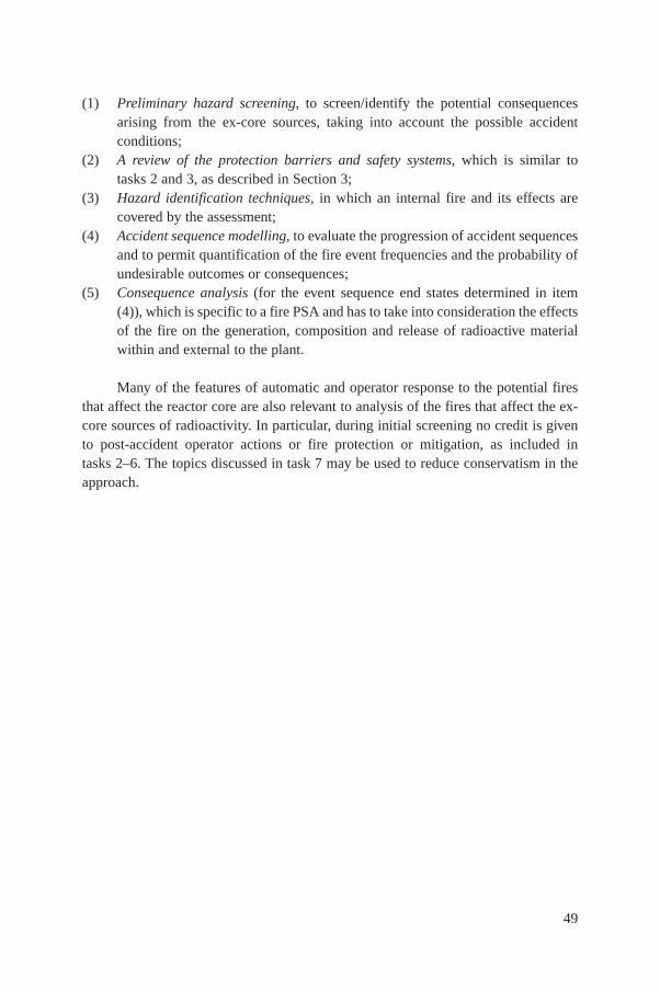
(1) Preliminary hazard screening, to screen/identify the potential consequencesarising from the ex-core sources, taking into account the possible accidentconditions;
(2) A review of the protection barriers and safety systems, which is similar totasks 2 and 3, as described in Section 3;
(3) Hazard identification techniques, in which an internal fire and its effects arecovered by the assessment;
(4) Accident sequence modelling, to evaluate the progression of accident sequencesand to permit quantification of the fire event frequencies and the probability ofundesirable outcomes or consequences;
(5) Consequence analysis (for the event sequence end states determined in item(4)), which is specific to a fire PSA and has to take into consideration the effectsof the fire on the generation, composition and release of radioactive materialwithin and external to the plant.
Many of the features of automatic and operator response to the potential firesthat affect the reactor core are also relevant to analysis of the fires that affect the ex-core sources of radioactivity. In particular, during initial screening no credit is givento post-accident operator actions or fire protection or mitigation, as included intasks 2–6. The topics discussed in task 7 may be used to reduce conservatism in theapproach.
49
51
Appendix I
INFORMATION REQUIRED FROM AND IN ADDITION TOTHE INTERNAL EVENTS PSA MODEL
I.1. INFORMATION IN THE INTERNAL EVENTS PSA MODEL
A simplified diagram of the electrical and control circuit is given in Fig. I.1, andshows the power circuit that provides the motive power to a pump motor, e.g. anemergency coolant injection pump or an auxiliary feedwater pump. The motive powerto a pump is derived from one of the plant’s electric power buses, perhaps via atransformer. Activation of a pump is controlled by the switchgear, usually located inan individual bus cabinet. In turn, this switchgear requires low voltage power foroperation, in addition to control signalling. The latter is obtained via a control relay,which responds to demand signals from either the control room or the automaticactuation system.
FIG. I.1. The elecrical and control circuit that provides motive power.
MMotor
actuator
High voltageswitchgear(cabinet)
Transformerbus
Low voltageswitchgear power
Automaticactuation,
e.g. safeguardsSensors
Controlrelay
Controlpanel
Motive power supply cables
Low voltage power supply
Control cables/signals
Boxes represent the ‘active’components that are locatedin specific areas of the plant

Each of these discrete components may be located in a different area of theplant. The internal events PSA model should have taken into consideration theindividual failure modes of these components, either explicitly or, in some cases,implicitly. For example, the failure of a pump to start on demand may be caused byinherent pump motor failures or no electric power supply. The causes of such anelectric power supply failure can be modelled as follows:
(1) Loss of the power supply from the bus, or switchgear failure (to provide thepower supply when given the demand signal), or loss of the low voltage powersupply to the switchgear;
or in a basic simplified form:
(2) No electric power is supplied to the pump motor,
which includes the three failure modes specified in item (1).Similarly, the PSA models may have considered the details of control system
operation, or have treated the failure modes in a simplistic manner.The internal events PSA does not usually have specifically modelled cable
failures, i.e. the electrical links between the ‘active’ components in the example.
I.2. FIRE PSA NEEDS
In addition to the active components that are to be found in the internal eventsmodel, shown by boxes in Fig. I.1, details of the cable paths between components arecritical to the analysis. A fire induced failure in any of the cable routes shown has thepotential to affect the successful operation of components, which together supportoperation of the motor. Similar principles apply to actuated valves.
It should be recognized that the cable routes shown will almost certainlyinvolve a number of additional areas of the plant, including those rooms or tunnelsthat contain only cables. Thus, an analysis based solely on the location of the ‘active’components in the PSA will be incomplete and not reflect the real fire risk.
I.3. HOT SHORT POTENTIAL
In Section 3.3.5, the possibility of hot shorts in control cables is identified.Thus, referring to the schematic diagram, hot shorts occurring in any of the controlcircuits that provide an actuation signal to the switchgear, which supplies thecomponent with motive electric power, should be considered in the analysis.
52

Deleterious hot shorts in the power supply circuits (high or low voltage), or incircuits that are disabled (i.e. not ‘active’ or ‘live’), e.g. because of removal of a fuse,are not considered possible, and are therefore excluded.
I.4. OUTPUT
The inventory of cable paths produced under task 3 of the fire PSA may thus bedeveloped by one of two alternative means:
(1) For each ‘active’ component established as being fire PSA related, identify thecable paths between the component and its electric power and control sources(the cables shown in Fig. I.1). The analysis will thus be restricted to thosecompartments and cells that contain fire PSA related components.
(2) For each fire compartment or cell, identify the PSA related system components(including cables) that are located in the compartment or cell. Some of thisinformation may already be available from an existing fire hazard analysis.
It is recommended that the results of the analysis be incorporated into adatabase (or a number of linked databases) that will be used in subsequent tasks andin reporting the fire PSA.
53
Appendix II
ESSENTIAL EQUIPMENT MALFUNCTIONS RESULTING FROM FIRE INDUCED DAMAGE
TO NON-ESSENTIAL CIRCUITS
The following examples are extracted from guidelines developedby the United States Department of Energy [12]
II.1. INTRODUCTION
The examples provided in this Appendix illustrate the indirect effects of a fireresulting from fire induced damage to the associated cabling in non-essential circuits.Sections II.2 and II.3 show the effects of short circuit overcurrent protection in theevent of low and high impedance faults, respectively, in non-essential circuits.Section II.4 gives an example of the physical propagation of a fire between non-essential and essential circuits, and Section II.5 illustrates the effects ofsecondary ignition caused by fire induced overcurrent conditions.
II.2. LOW IMPEDANCE FAULTS
In the event of a low impedance fault of an associated non-essential circuit, thecircuit comes into contact with the ground, which results in a high short circuitcurrent and leads to interruption of the faulted circuit by a protective device. If theprotective devices used at various levels of the power supply circuit are not properlyco-ordinated (to provide selective tripping), the power supply to the required (PSArelated) equipment may be interrupted. In a properly co-ordinated circuit, fireinitiated faults are rapidly isolated by the protective device located nearest to the faultbefore the fault current propagates, causing the tripping of any protective deviceupstream of the required power supply.
An example situation is illustrated in Fig. II.1. A fire in a single fire compartment(II) damages essential (PSA related) pump B and non-essential pump X, and theircabling. Since non-essential pump X is not redundant, nuclear safety appears to bemaintained. However, if circuit breakers 1 and 2 are not properly co-ordinated, themain breaker 1 may trip on a short circuit overcurrent prior to the tripping of breaker 2, interrupting the power supply to the required (PSA related) pump A.
54

55
FIG. II.1. Indirect effects of fire induced damage in a non-essential circuit (low impedancefaults).
Fire location
Bus A Bus B
A
X
Fire compartment I
Redundant pumps
PSA relatedpump A
B
Pump X
PSA relatedpump B
Fire compartment II
1
2
Safe shutdown bus A
1000 A
Pump A
PSA relatedcomponent
Fire affected area
To non-essential equipment
Fire barrierwalls/floor/ceiling
Safe shutdown bus B
Pump B
PSA relatedcomponent
FIG. II.2. Indirect effects of fire induced damage in a non-essential circuit (high impedancefaults).
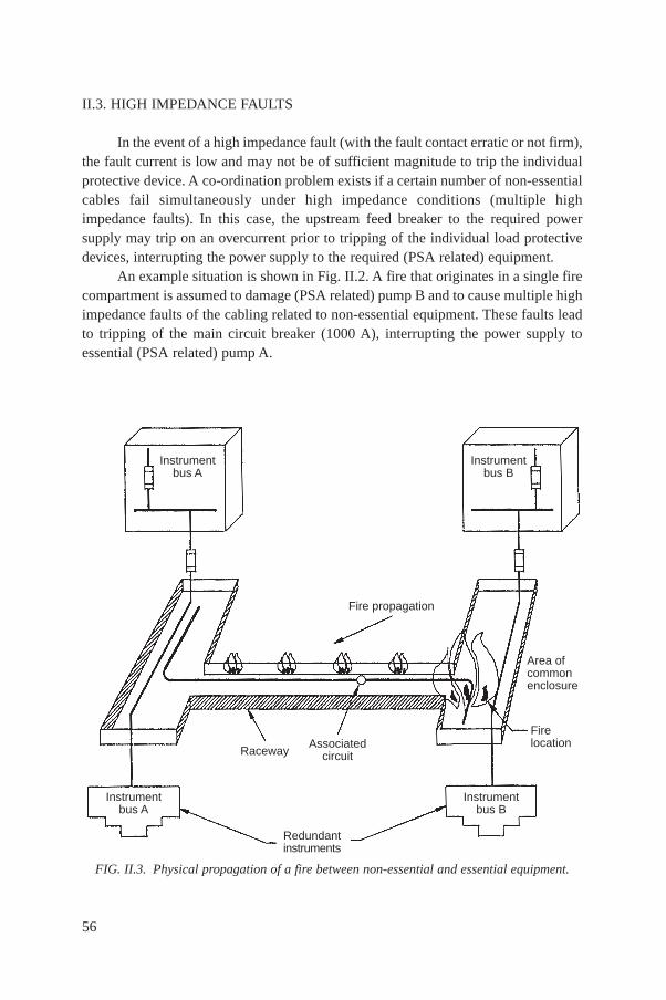
II.3. HIGH IMPEDANCE FAULTS
In the event of a high impedance fault (with the fault contact erratic or not firm),the fault current is low and may not be of sufficient magnitude to trip the individualprotective device. A co-ordination problem exists if a certain number of non-essentialcables fail simultaneously under high impedance conditions (multiple highimpedance faults). In this case, the upstream feed breaker to the required powersupply may trip on an overcurrent prior to tripping of the individual load protectivedevices, interrupting the power supply to the required (PSA related) equipment.
An example situation is shown in Fig. II.2. A fire that originates in a single firecompartment is assumed to damage (PSA related) pump B and to cause multiple highimpedance faults of the cabling related to non-essential equipment. These faults leadto tripping of the main circuit breaker (1000 A), interrupting the power supply toessential (PSA related) pump A.
56
FIG. II.3. Physical propagation of a fire between non-essential and essential equipment.
Instrumentbus A
RacewayAssociated
circuit
Fire propagation
Area ofcommonenclosure
Firelocation
Redundantinstruments
Instrumentbus B
Instrumentbus B
Instrumentbus A

57
II.4. PHYSICAL PROPAGATION OF A FIRE
Physical propagation of a fire from one location to another may occur wherematerials are present that can burn. The fire may spread from a non-critical to acritical fire area through exposed cables that contain non-retardant material and arenot protected by fire stops. An example situation is shown in Fig. II.3.
II.5. SECONDARY IGNITION
Fire initiated electrical faults in inadequately protected non-essential cablesmay lead to overcurrent conditions, resulting in secondary ignition. A secondary firewill damage those essential cables that share a common enclosure. An example isshown in Fig. II.4.
FIG. II.4. Secondary ignition of a fire caused by a short circuit overcurrent in non-essentialequipment.
Instrumentbus A
RacewayAssociated
circuit
Fire barrier
Area ofcommonenclosure
Fire location
Redundantinstruments
Instrumentbus B
Instrumentbus B
Instrumentbus A
Potentialsecondary firecaused bycable ignition
Firecompartment II
Firecompartment I

Secondary ignition may also occur in secondary winding of the control powertransformers because of an open circuit caused by the effects of a fire. The currentpower transformers used throughout the electrical distribution system to monitor buscurrent are designed to transform high primary current into low secondary current.Because of the high primary to secondary current ratio, an opening in the secondarycircuit produces excessively high voltages and may result in ignition of thetransformer materials. An example situation is shown in Fig. II.5.
58
Fire location
Switchgear room A
A
Control room
B
Safe shutdownbus A
PSA related components
A
B
Switchgear room B
Safe shutdownbus B
FIG. II.5. Secondary ignition of a fire caused by open current transformer secondarywindings.
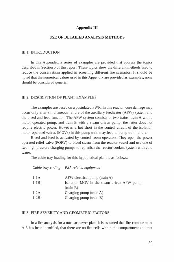
Appendix III
USE OF DETAILED ANALYSIS METHODS
III.1. INTRODUCTION
In this Appendix, a series of examples are provided that address the topicsdescribed in Section 5 of this report. These topics show the different methods used toreduce the conservatism applied in screening different fire scenarios. It should benoted that the numerical values used in this Appendix are provided as examples; noneshould be considered generic.
III.2. DESCRIPTION OF PLANT EXAMPLES
The examples are based on a postulated PWR. In this reactor, core damage mayoccur only after simultaneous failure of the auxiliary feedwater (AFW) system andthe bleed and feed function. The AFW system consists of two trains: train A with amotor operated pump, and train B with a steam driven pump; the latter does notrequire electric power. However, a hot short in the control circuit of the isolationmotor operated valves (MOVs) in this pump train may lead to pump train failure.
Bleed and feed is activated by control room operators. They open the poweroperated relief valve (PORV) to bleed steam from the reactor vessel and use one oftwo high pressure charging pumps to replenish the reactor coolant system with coldwater.
The cable tray loading for this hypothetical plant is as follows:
Cable tray coding PSA related equipment
1-1A AFW electrical pump (train A)1-1B Isolation MOV in the steam driven AFW pump
(train B)1-2A Charging pump (train A)1-2B Charging pump (train B)
III.3. FIRE SEVERITY AND GEOMETRIC FACTORS
In a fire analysis for a nuclear power plant it is assumed that fire compartmentA-3 has been identified, that there are no fire cells within the compartment and that
59
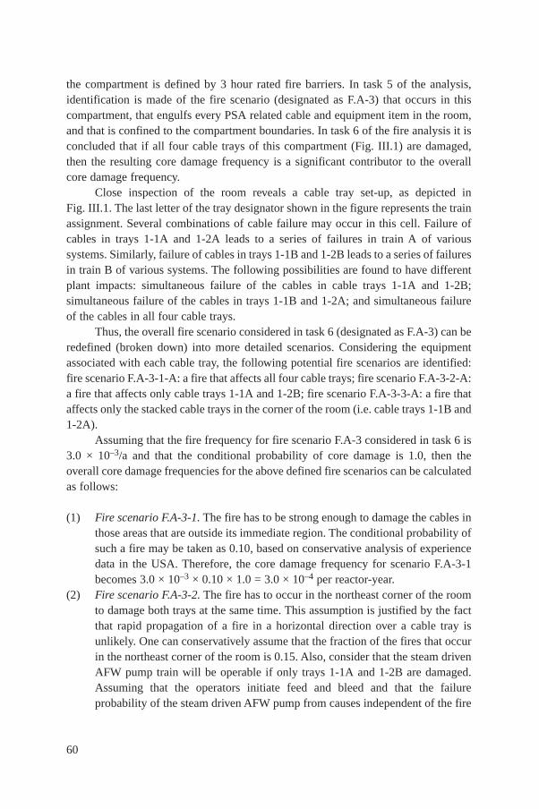
the compartment is defined by 3 hour rated fire barriers. In task 5 of the analysis,identification is made of the fire scenario (designated as F.A-3) that occurs in thiscompartment, that engulfs every PSA related cable and equipment item in the room,and that is confined to the compartment boundaries. In task 6 of the fire analysis it isconcluded that if all four cable trays of this compartment (Fig. III.1) are damaged,then the resulting core damage frequency is a significant contributor to the overallcore damage frequency.
Close inspection of the room reveals a cable tray set-up, as depicted inFig. III.1. The last letter of the tray designator shown in the figure represents the trainassignment. Several combinations of cable failure may occur in this cell. Failure ofcables in trays 1-1A and 1-2A leads to a series of failures in train A of varioussystems. Similarly, failure of cables in trays 1-1B and 1-2B leads to a series of failuresin train B of various systems. The following possibilities are found to have differentplant impacts: simultaneous failure of the cables in cable trays 1-1A and 1-2B;simultaneous failure of the cables in trays 1-1B and 1-2A; and simultaneous failureof the cables in all four cable trays.
Thus, the overall fire scenario considered in task 6 (designated as F.A-3) can beredefined (broken down) into more detailed scenarios. Considering the equipmentassociated with each cable tray, the following potential fire scenarios are identified:fire scenario F.A-3-1-A: a fire that affects all four cable trays; fire scenario F.A-3-2-A:a fire that affects only cable trays 1-1A and 1-2B; fire scenario F.A-3-3-A: a fire thataffects only the stacked cable trays in the corner of the room (i.e. cable trays 1-1B and1-2A).
Assuming that the fire frequency for fire scenario F.A-3 considered in task 6 is3.0 × 10–3/a and that the conditional probability of core damage is 1.0, then theoverall core damage frequencies for the above defined fire scenarios can be calculatedas follows:
(1) Fire scenario F.A-3-1. The fire has to be strong enough to damage the cables inthose areas that are outside its immediate region. The conditional probability ofsuch a fire may be taken as 0.10, based on conservative analysis of experiencedata in the USA. Therefore, the core damage frequency for scenario F.A-3-1becomes 3.0 × 10–3 × 0.10 × 1.0 = 3.0 × 10⁻⁴ per reactor-year.
(2) Fire scenario F.A-3-2. The fire has to occur in the northeast corner of the roomto damage both trays at the same time. This assumption is justified by the factthat rapid propagation of a fire in a horizontal direction over a cable tray isunlikely. One can conservatively assume that the fraction of the fires that occurin the northeast corner of the room is 0.15. Also, consider that the steam drivenAFW pump train will be operable if only trays 1-1A and 1-2B are damaged.Assuming that the operators initiate feed and bleed and that the failureprobability of the steam driven AFW pump from causes independent of the fire
60
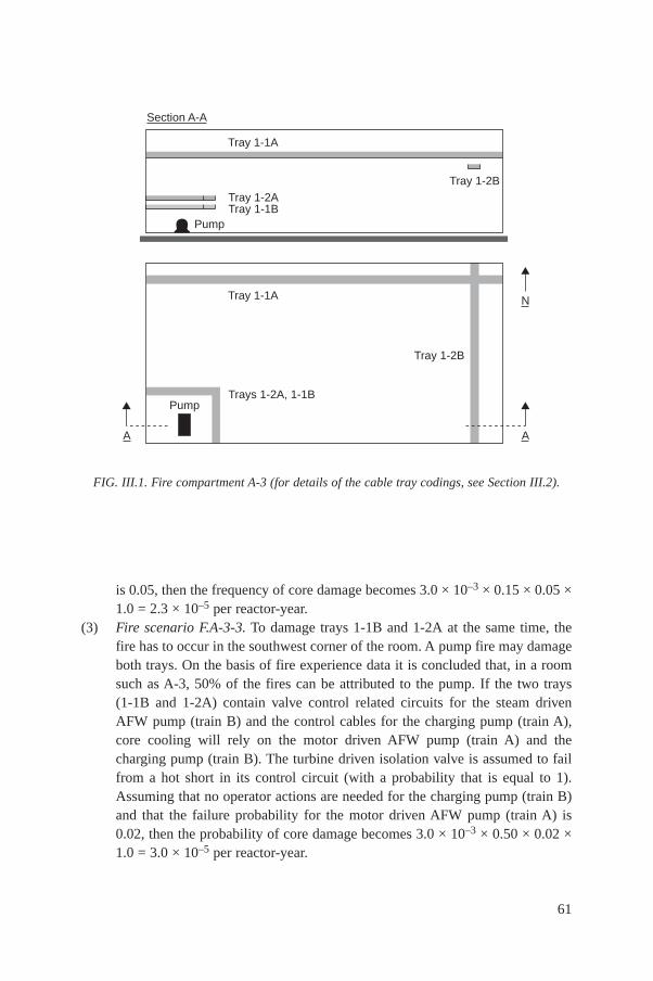
is 0.05, then the frequency of core damage becomes 3.0 × 10–3 × 0.15 × 0.05 ×1.0 = 2.3 × 10⁻⁵ per reactor-year.
(3) Fire scenario F.A-3-3. To damage trays 1-1B and 1-2A at the same time, thefire has to occur in the southwest corner of the room. A pump fire may damageboth trays. On the basis of fire experience data it is concluded that, in a roomsuch as A-3, 50% of the fires can be attributed to the pump. If the two trays(1-1B and 1-2A) contain valve control related circuits for the steam drivenAFW pump (train B) and the control cables for the charging pump (train A),core cooling will rely on the motor driven AFW pump (train A) and thecharging pump (train B). The turbine driven isolation valve is assumed to failfrom a hot short in its control circuit (with a probability that is equal to 1).Assuming that no operator actions are needed for the charging pump (train B)and that the failure probability for the motor driven AFW pump (train A) is0.02, then the probability of core damage becomes 3.0 × 10–3 × 0.50 × 0.02 ×1.0 = 3.0 × 10⁻⁵ per reactor-year.
61
FIG. III.1. Fire compartment A-3 (for details of the cable tray codings, see Section III.2).
A A
N
Tray 1-1A
Tray 1-2A
Pump
Tray 1-2B
Tray 1-1B
Tray 1-2B
Tray 1-1A
Trays 1-2A, 1-1BPump
Section A-A

III.4. HOT SHORT
Consider the simplified valve control circuit diagram outlined in Fig. III.2. Afire in compartment A-3 is very unlikely to lead to valve failure, since only a threephase power cable is present in that compartment. Thus, in computing the coredamage frequency for compartment A-3, a hot short in the turbine driven AFW pumpisolation valve can be set at a probability that is equal to zero. The steam turbinedriven pump failure probability used in F.A-3-2 can then be used in fire scenariosF.A-3-1 and F.A-3-3: for fire scenario F.A-3-1, the core damage frequency becomes3.0 × 10–3 × 0.10 × 0.05 × 1.0 = 1.5 × 10⁻⁵ per reactor-year; and for fire scenarioF.A-3-3, the core damage frequency becomes 3.0 × 10–3 × 0.50 × 0.02 × 0.05 × 1.0= 1.5 × 10⁻⁶ per reactor-year.
As another example, again using Fig. III.2, a fire in compartment A-2 may leadto an intracable hot short, i.e. the action of the control switch may be simulated if twowires inside the cable come into contact with one another. Figure III.3 shows thepossible positions of the cable where these wires are located in a cable tray, and across-section of a multiwire cable. In this case, the cable of concern contains manyindividual conductors, of which only two are of interest to the fire PSA. A risk
62
FIG. III.2. Valve control circuit.
Electricalcabinet room
Cable room
S
Solenoid
Valve room
Compartment A-3
Control switch
Control room
Compartment A-2
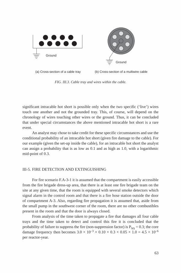
significant intracable hot short is possible only when the two specific (‘live’) wirestouch one another and not the grounded tray. This, of course, will depend on thechronology of wires touching other wires or the ground. Thus, it can be concludedthat under special circumstances the above mentioned intracable hot short is a rareevent.
An analyst may chose to take credit for these specific circumstances and use theconditional probability of an intracable hot short (given fire damage to the cable). Forour example (given the set-up inside the cable), for an intracable hot short the analystcan assign a probability that is as low as 0.1 and as high as 1.0, with a logarithmicmid-point of 0.3.
III-5. FIRE DETECTION AND EXTINGUISHING
For fire scenario F.A-3-1 it is assumed that the compartment is easily accessiblefrom the fire brigade dress-up area, that there is at least one fire brigade team on thesite at any given time, that the room is equipped with several smoke detectors whichsignal alarm in the control room and that there is a fire hose station outside the doorof compartment A-3. Also, regarding fire propagation it is assumed that, aside fromthe small pump in the southwest corner of the room, there are no other combustiblespresent in the room and that the door is always closed.
From analysis of the time taken to propagate a fire that damages all four cabletrays and the time taken to detect and control this fire it is concluded that theprobability of failure to suppress the fire (non-suppression factor) is PNS = 0.3; the coredamage frequency then becomes 3.0 × 10–3 × 0.10 × 0.3 × 0.05 × 1.0 = 4.5 × 10⁻⁶
per reactor-year.
63
FIG. III.3. Cable tray and wires within the cable.
Ground
Ground
(a) Cross-section of a cable tray (b) Cross-section of a multiwire cable
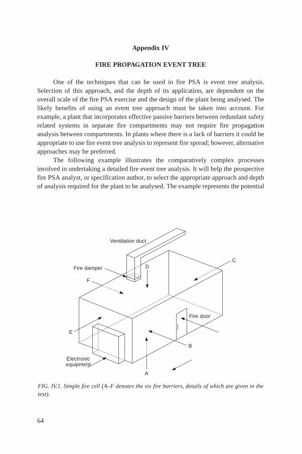
Appendix IV
FIRE PROPAGATION EVENT TREE
One of the techniques that can be used in fire PSA is event tree analysis.Selection of this approach, and the depth of its application, are dependent on theoverall scale of the fire PSA exercise and the design of the plant being analysed. Thelikely benefits of using an event tree approach must be taken into account. Forexample, a plant that incorporates effective passive barriers between redundant safetyrelated systems in separate fire compartments may not require fire propagationanalysis between compartments. In plants where there is a lack of barriers it could beappropriate to use fire event tree analysis to represent fire spread; however, alternativeapproaches may be preferred.
The following example illustrates the comparatively complex processesinvolved in undertaking a detailed fire event tree analysis. It will help the prospectivefire PSA analyst, or specification author, to select the appropriate approach and depthof analysis required for the plant to be analysed. The example represents the potential
64
FIG. IV.1. Simple fire cell (A–F denotes the six fire barriers, details of which are given in thetext).
Ventilation duct
Fire damper
F
E
Fire door
B
CD
A
Electronicequipment
routes through which a fire initiated within the simple fire cell (Fig. IV.1) can develop.The fire cell has six fire barriers (A–F) with the following features: barriers A, C andF are fully fire rated and will not fail, even if the fire in the cell is not suppressed;barriers B, D and F have only a limited fire rating and may eventually fail if the firein the cell is not suppressed; barrier B incorporates a fire rated door (which could beleft open); barrier D incorporates a fire damper (which could fail to close); and barrierE has sensitive electronic equipment mounted on it in the adjacent cell.
Depending on the successful action of the fire suppression systems, the fireinitiated in the cell progresses from a pilot fire to a developed fire and results in aseries of outcomes, each of which is provided with a specific path number. Other cellscan be affected by the fire as a result of fire spread through a failed or open barrier,fire or smoke spread through a ventilation duct or open barrier, and heat transferthrough an intact barrier. The event tree shown in Fig. IV.2 represents possiblecombinations of events (scenarios).
More detailed information on the scenarios defined by the event tree is providedin Table IV.I for each specific path (1–38). For scenarios in which other cells areaffected by the spread of hazard, information is provided on the barrier(s) breached(B, D, E) and the type of hazard being spread.
With regard to the effects of a fire (smoke, heat) on the adjacent cells, thefollowing assumptions are made for this example:
Bs = Door open — early suppression fails — smoke spread;Bf = Door open — late suppression fails — fire spread through barrier B only;Ds = Damper open — early suppression fails — smoke spread through the ventila-
tion duct;Dg = Damper open — late suppression fails — fire spread through the ventilation
duct;Eh = Door closed — all suppression fails — heat transfer through intact barrier;Bf, Df, Ef = All suppression fails and barrier fails — fire spread.
Two groups of scenarios are distinguished: those in which the fire is containedin the cell, and those in which the fire spreads to other cells. The first group alsoincludes cases where cold smoke spreads through an open barrier and heat transferthrough an intact barrier. For fires contained in the cell, the effects on the plant canbe identified (at this stage of analysis) for each of the consequential damagecategories (designated i–vii). In cases where other cells are affected by hot gas or firespread through a ventilation duct or a failed barrier, the total damage state cannot beevaluated at this stage. It is assessed when the consequences of a fire spread into theaffected cell(s) have been evaluated.
Figure IV.2 and Table IV.I illustrate that the effect on other cells can be the samefor several fire spread sequences. In this case, there are three fire spread scenarios
65

(1–3 in the fourth column of Table IV.I). The associated frequencies can therefore besummed to provide a reduced number of sequences for analysis of a fire spread intothe adjacent cells.
66
FIG. IV.2. Fire propagation event tree.
Pat
h N
o.
Pilot fire Developed fireF
requ
ency
of f
irein
itiat
ion
Fire
det
ectio
n, e
arly
Roo
m c
losu
re,
fire
door
clo
sed
Roo
m c
losu
re,
fire
dam
per
clos
ed
Fire
sup
pres
sion
, ear
ly;
fixed
inst
alle
d eq
uipm
ent
Fire
sup
pres
sion
,po
rtab
le e
xtin
guis
her
Equ
ipm
ent d
amag
e fr
omsu
ppre
ssio
n ag
ent
Fire
sup
pres
sion
, lat
e;fix
ed in
stal
led
equi
pmen
tor
trai
ned
fire
fight
ers
Fire
det
ectio
n, la
te
Roo
m e
nclo
sure
does
not
fail
No
Yes

67
1234567891011121314151617181920212223242526272829303132333435363738
TABLE IV.I. CONSEQUENTIAL DAMAGE CATEGORIES FOR INDIVIDUALSCENARIOS DEFINED BY THE EXAMPLE EVENT TREE
Sequence frequency
Path Other cells Damage Fire spread (1/a)
No. affected category sequence Contained Dg Eh Bf Bf Df Efsequences
Note 1: (i)–(vii) = different damage states (for fires contained in the cell).Note 2: * = sequence frequencies to be inserted.Note 3: Subscripts = s: cold smoke; h: heat transfer through an intact barrier; g: fire spread through a
ventilation duct; and f: fire spread through a failed (or open) barrier.
EhBf Df Ef
Ds Dg EhBf Df Ef
BsBf
DsBf Df Ef
EhBf Df EfEhBf Df EfDsDg EhBf Df EfDg EhBf Df EfBsBfBfDsBfBf
iiiiiiivv
iiiiiivi
iiiiiivii
iiiiiivi
ivv
v
vi
vii
vi
– *– *– *– *– *1 *– *– *– *– *2 *1 *– *– *– *– *3 *– *– *– *– *1 *– *– *1 * *– *1 * *– *2 *1 * *2 *1 * *– *3 *3 *– *3 *3 *
Σ* Σ* Σ* Σ*

Assessment of a fire spread through an adjacent cell (or possibly a remote cellif spread through a ventilation duct) is carried out in a similar manner, using sequencefrequency as the frequency for the ‘initiating’ pilot fire in the adjacent cell. Care mustbe exercised by considering cases where the fire may have developed beyond the pilotstage (e.g. because of fire barrier failure).
Account should be taken of the frequency of individual path sequences as theyprogress through one or more cells. If the path sequence frequency falls below apredefined limit, the sequence should be terminated and discounted as being notcredible.
68
Appendix V
POTENTIAL FOR LOSS OF THEALTERNATE SHUTDOWN CAPABILITY
DURING A CONTROL ROOM FIRE
The following example is extracted from United States Nuclear Regulatory Commission Information Notice 92-18 [25]
The example provided in this Appendix describes the conditions that couldresult in the loss of capability to maintain the reactor in a safe shutdown condition inthe event of a control room fire. It is shown that certain MOVs needed to shut downthe reactor and to maintain it in a safe shutdown condition may, as a result of hotshorts combined with the bypass of thermal overload protection, be damaged beforethe operator shifts control of the valves to the alternate shutdown panel.
Fig. V.1 is a conceptual diagram of the control circuitry for MOVs and includesthe relay coils that operate the contactors in the power circuitry for the motors. Itshould be noted that the torque and limit switches in the valve operator are located ina manner such that they can be bypassed in the event of a hot short.
Fig. V.2 provides an example of the manner in which the motor of a closedMOV can be energized and damaged by a hot short if its overload protection isbypassed. The hot short bypasses the push button normally used to close the MOV,thus providing the power to drive the motor in a closed direction. The power is notdisconnected from the motor, although it has stalled; the current and torque areabnormally high, possibly causing electrical failure to the motor windings andmechanical damage to the valve. Such mechanical damage may be sufficient toprevent reactor operators from manually operating the valve. A similar problem canoccur for open MOVs (see Fig. V.3). Shorts to other sources of power also causefailure of the MOVs.
69

70
FIG. V.1. Control circuitry for the motor operated valves (MOVs).
Transfer
RSP
G
R
VO
LC
LO
O
C
CR
O
C
MCC
MO
MC
G
R
Contact actuation points
Open Valve stroke Closed
LO
LC
T
The lines indicate that the switch contacts are closed.The points indicate the valve positions where the switchcontacts open and close. For the torque switch, thecontacts are actuated by the position of the valve discat mid-stroke and by the preset torque at the end of theclosing stroke.
CR = Control roomRSP = Remote shutdown panelMCC = Motor control centreVO = Valve operatorMC = Relay coil – close valveMO = Relay coil – open valveC = Push button – close valveO = Push button – open valveLC = Limit switch – close valveLO = Limit switch – open valveT = Torque switchG = Green lampR = Red lamp
T

71
FIG. V-2. Postulated hot short that occurs while a MOV is closed (see Fig. V.1 for details ofabbreviations).
Transfer
RSP
G
R
VO
LC
LO
O
C
CR
O
C
MCC
MO
MC
G
R
T
FIG. V.3. Postulated hot short that occurs while a MOV is open (see Fig. V.1 for details ofabbreviations).
Transfer
RSP
G
R
VO
LC
LO
O
C
CR
O
C
MO
MC
G
R
S
MCC
T
REFERENCES
[1] INTERNATIONAL ATOMIC ENERGY AGENCY, Preparation of Fire HazardAnalyses for Nuclear Power Plants, Safety Reports Series No. 8, IAEA, Vienna (1998).
[2] INTERNATIONAL ATOMIC ENERGY AGENCY, Evaluation of Fire HazardAnalyses for Nuclear Power Plants, Safety Series No. 50-P-9, IAEA, Vienna (1995).
[3] INTERNATIONAL ATOMIC ENERGY AGENCY, Fire Protection in Nuclear PowerPlants, Safety Series No. 50-SG-D2 (Rev. 1), IAEA, Vienna (1992).
[4] INTERNATIONAL ATOMIC ENERGY AGENCY, Procedures for ConductingProbabilistic Safety Assessments of Nuclear Power Plants (Level 1), Safety SeriesNo. 50-P-4, IAEA, Vienna (1992).
[5] INTERNATIONAL ATOMIC ENERGY AGENCY, Treatment of External Hazards inProbabilistic Safety Assessment for Nuclear Power Plants, Safety Series No. 50-P-7,IAEA, Vienna (1995).
[6] INTERNATIONAL ATOMIC ENERGY AGENCY, Procedures for ConductingIndependent Peer Reviews of Probabilistic Safety Assessment, IAEA-TECDOC-543,IAEA, Vienna (1990).
[7] KAZARIANS, M., SIU, N.O., APOSTOLAKIS, G., Risk analysis for nuclear powerplants: Methodological development and applications, Risk Anal. 5 1 (1985).
[8] PARKINSON, W., et al., Fire Events Database for U.S. Nuclear Power Plants, EPRINSAC-178L (Rev. 1), Electric Power Research Institute, Palo Alto, CA (1993).
[9] WHEELIS, W.T., Users Guide for a Personal-Computer-Based Nuclear Power PlantFire Data Base, SAND86-0300, NUREG/CR-4638, Sandia National Laboratories,Albuquerque, NM (1986).
[10] ELECTRIC POWER RESEARCH INSTITUTE, Fire Induced Vulnerability EvaluationMethodology (FIVE), Plant Screening Guide, EPRI9 Rev., EPRI, Palo Alto, CA(1991).
[11] GUYMER, P., PARRY, G.W., “Use of probabilistic methods in fire hazard analysis”,Fire Protection and Fire Fighting in Nuclear Installations (Proc. Symp. Vienna, 1989),IAEA, Vienna (1989) 485–504.
[12] UNITED STATES DEPARTMENT OF ENERGY, Reactor Core Protection EvaluationMethodology for Fires at Soviet Designed RBMK and VVER Nuclear Power Plants,Rep. DOE/NE-0113, DOE, Washington, DC (1996).
[13] UNITED STATES DEPARTMENT OF ENERGY, Fire Tests of Wire and Cable forDOE Nuclear Facilities, Rep. UCRL-ID-110598, DOE Washington, DC (1992).
[14] INTERNATIONAL ATOMIC ENERGY AGENCY, Fire Hazard Analysis for WWERNuclear Power Plants, IAEA-TECDOC-778, IAEA, Vienna (1994).
[15] KAZARIANS, M., APOSTOLAKIS, G., “Modelling rare events: The frequencies offires in nuclear power plants”, Paper presented at a Workshop on Low Probability/HighConsequence Risk Analysis, Arlington, VA, 1982.
[16] KAZARIANS, M., APOSTOLAKIS, G., Fire Risk Analysis for Nuclear Power Plants,UCLA/ENG-8102, NUREG/CR-2258, United States Nuclear Regulatory Commission,Washington, DC (1981).
73
[17] INTERNATIONAL ATOMIC ENERGY AGENCY, Human Reliability Analysis inProbabilistic Safety Assessment for Nuclear Power Plants, Safety Series No. 50-P-10,IAEA, Vienna (1995).
[18] SIU, N.O., APOSTOLAKIS, G., “Modelling the detection and suppression of fires innuclear power plants”, Paper presented at the American Nuclear Society/EuropeanNuclear Society Topical Meeting on Probabilistic Safety Methods and Applications,San Francisco, CA, 1985.
[19] SIU, N.O., APOSTOLAKIS, G., Modelling the detection rates of fires in nuclearplants: Development and application of a methodology for treating imprecise evidence,Risk Anal. 6 1 (1986) 43–59.
[20] SIU, N.O., APOSTOLAKIS, G., A methodology for analysing the detection and sup-pression of fires in nuclear power plants, Nucl. Sci. Eng. 94 (1986) 213–226.
[21] AZARM, M.A., BOCCIO, J.L., Probability Based Evaluation of Selected FireProtection Features in Nuclear Power Plants, NUREG/CR-4230, United States NuclearRegulatory Commission, Washington, DC (1985).
[22] FRIEDMAN, R., An international survey of computer models for fire and smoke, J. FireProt. Eng. 4 3 (1992) 81–92.
[23] UNITED STATES NUCLEAR REGULATORY COMMISSION, Severe AccidentRisks: An Assessment for Five US Nuclear Power Plants, Final Summary Report,NUREG/CR-1150, 3 vols, NRC, Washington, DC (1990).
[24] INTERNATIONAL ATOMIC ENERGY AGENCY, Use of Probabilistic SafetyAssessment for Nuclear Installations with a Large Inventory of Radioactive Material,IAEA-TECDOC-711, IAEA, Vienna (1993).
[25] UNITED STATES NUCLEAR REGULATORY COMMISSION, Potential for Loss ofRemote Shutdown Capability During a Control Room Fire, Information Notice 92-18,NRC, Washington, DC (1992).
74

CONTRIBUTORS TO DRAFTING AND REVIEW
Adam, M.J.M. Scottish Nuclear Ltd, United Kingdom
Afzali, A. Scientech, Inc., United States of America
Almasy, M. Belgatom S.A., Belgium
Araiza-Martínez, E. Comisión Nacional de Seguridad Nuclear y Salvaguardias, Mexico
Argirov, J. Bulgarian Academy of Sciences, Bulgaria
Bacellar Leal Ferreira, R. Furnas Centrais Eléctricas S.A., Brazil
Balasubramanian, G.R. Atomic Energy Commission, India
Barends, P.J. Ministry of Home Affairs, Netherlands
Berg, H.P. Bundesamt für Strahlenschutz, Germany
Bergström, L.U.S. Vattenfall Energiesystem AB, Sweden
Boleman, M. Bohunice Nuclear Power Plant, Slovakia
Chapus, J. Electricité de France, France
Cottaz, M. Commissariat à l’énergie atomique, France
Covelli, B. Tecova AG, Switzerland
Ducamp, F. Commissariat à l’énergie atomique, France
Gorman, K.L. Scottish Nuclear Ltd, United Kingdom
Haighton, A. Nuclear Electric plc, United Kingdom
Hoffmann, H.H. ABB Reaktor GmbH, Germany
Jones, G. HM Nuclear Installations Inspectorate, United Kingdom
Kabanov, L. International Atomic Energy Agency
Kaercher, M. Electricité de France, France
75

Kazarians, M. Kazarians & Associates, United States of America
Kelemen, I. Power Engineering and Contractor Company, Hungary
Kolář, L. Nuclear Research Institute Řež, Czech Republic
Kulig, M.J. International Atomic Energy Agency(Scientific Secretary)
Kvarčák, M. Technical University of Ostrava, Czech Republic
Lacoue, L. Institut de protection et de sûreté nucléaire, France
Lewis, M.J. Electrowatt Engineering Services Ltd, United Kingdom
Martin, J.A.A. Policia Federal Argentina, Argentina
Marttila, J.J. Finnish Centre for Radiation and Nuclear Safety, Finland
Mowrer, D.S. HBS Professional Loss Control, United States of America
Muller, J. Cogéma SG/SPS, France
Nowlen, S.P. Sandia National Laboratories, United States of America
Pfister, D. Swiss Federal Nuclear Safety Inspectorate, Switzerland
Ramsey, C.B. United States Department of Energy, United States of America
Roy, F. Institut de protection et de sûreté nucléaire, France
Röwekamp, M. Gesellschaft für Anlagen- und Reaktorsicherheit, Germany
Rodríguez, C.E. Ente Nacional Regulador Nuclear, Argentina
Rohác, D. Mochovce Nuclear Power Plant, Slovakia
Schneider, U. Technische Universität Wien, Austria
Šenovský, M. Technical University of Ostrava, Czech Republic
Štván, F. Nuclear Research Institute Řež, Czech Republic
Smith, F.M. AEA Technology, United Kingdom
76

Uchida, T. Nuclear Power Engineering Corporation, Japan
Vandermiers, M.C. Tractebel S.A., Belgium
Wittmann, R. Siemens AG, Germany
Zeberli, W. Brandverhütungs-Dienst für Industrie und Gewerbe, Switzerland
Technical Committee Meetings
Vienna, Austria: 27–30 November 1995; 7–11 October 1996
Consultants Meetings
Vienna, Austria: 13–17 November 1995; 15–19 July 1996
77