tips on using a pc power supply for projects
TRANSCRIPT

Tips on Using a PC Power Supply for Projects.doc 11/6/2007
Tips on Using PC Power Supplies for Projects
PC power supplies (PC P/Ss) put out great amounts of current at various voltages (+/12, +/-5, +3.3VDC typical). There’s a ton of information on the web telling how to use them as general purpose power supplies in various projects. Here’s the basic information, plus more details are attached. Typical PC P/S Wire Color Code Ground Black +3.3V Orange or Violet +5V Red -5V White +12V Yellow -12V Blue PS_ON Gray or Green Just connect a jumper as shown below and tap off the output voltages in accordance with the table above.
Note: If any pin on the large connector has two wires connected to it (for example, small orange and large orange), those two wires may need to stay jumpered together to make the power supply function.
120 VAC input
Green or Gray
Black
PC Power Supply
(typical)
Jumper to simulate PC power switch

Home > Categories > Computers and Electronics> Hardware> Internal Components
The How-to Manual That You Can Edit
Add wikiHow to your Facebook Profile
How to Convert a Computer ATX Power Supply to a
Lab Power SupplyComputer power supplies cost around US$15,but lab power supplies can run you $100 or more! By converting the cheap (free) ATX power supplies that can be found in any discarded computer, you can get a phenomenal lab power supply with huge current outputs, short circuit protection, and very tight voltage regulation.
1. Unplug the power cord from the back of the computer. "Harvest" a power supply from a computer by opening up the case of the computer, locating the gray box that is the power supply unit, tracing the wires from the power supply to the boards and devices and disconnecting all the cables by unplugging them.
2. Remove the screws (typically 4) that attach the power supply to the computer case and remove the power supply.
3. Cut off the connectors (leave a few inches of wire on the connectors so that you can use them later on for other projects).
4. Discharge the power supply by either letting it sit unconnected for a few days, or by attaching a 10 ohm resistor between a black and red wire (from the power cables on the output side). Using a resistor will only take a few seconds to fully discharge the power supply.
5. Gather the parts you need: binding posts (terminals), a LED with a current-limiting resistor, a switch (optional), a power resistor (10 ohm, 10W or greater wattage, see Tips), and heat shrink tubing.
Steps [edit]
Page 1 of 6How to Convert a Computer ATX Power Supply to a Lab Power Supply - wikiHow
10/10/2007http://www.wikihow.com/Convert-a-Computer-ATX-Power-Supply-to-a-Lab-Power-Sup...
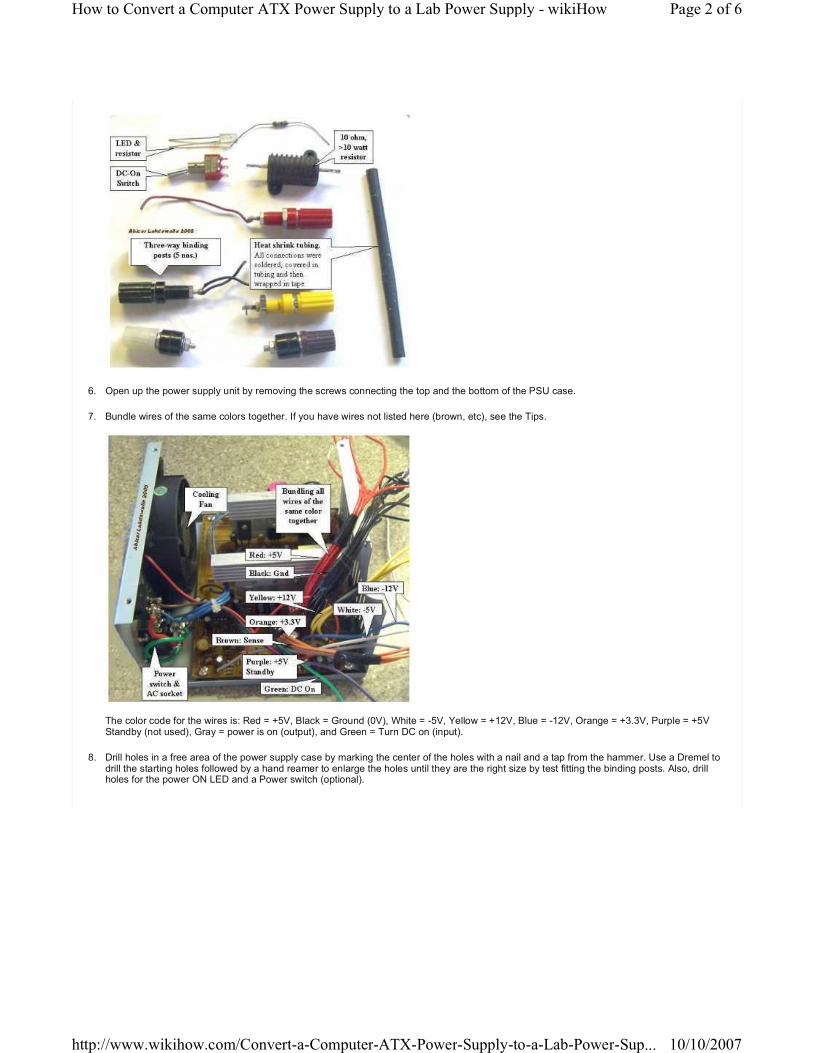
6. Open up the power supply unit by removing the screws connecting the top and the bottom of the PSU case.
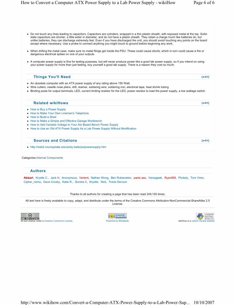
7. Bundle wires of the same colors together. If you have wires not listed here (brown, etc), see the Tips.
The color code for the wires is: Red = +5V, Black = Ground (0V), White = -5V, Yellow = +12V, Blue = -12V, Orange = +3.3V, Purple = +5V Standby (not used), Gray = power is on (output), and Green = Turn DC on (input).
8. Drill holes in a free area of the power supply case by marking the center of the holes with a nail and a tap from the hammer. Use a Dremel to drill the starting holes followed by a hand reamer to enlarge the holes until they are the right size by test fitting the binding posts. Also, drill holes for the power ON LED and a Power switch (optional).
Page 2 of 6How to Convert a Computer ATX Power Supply to a Lab Power Supply - wikiHow
10/10/2007http://www.wikihow.com/Convert-a-Computer-ATX-Power-Supply-to-a-Lab-Power-Sup...

9. Screw the binding posts into their corresponding holes and attach the nut on the back.
10. Connect all the pieces together.
� Connect one of the red wires to the power resistor, all the remaining red wires to the red binding posts;
� Connect one of the black wires to the other end of the power resistor, one black wire to a resistor (330 ohm) attached anode of the LED, one black wire to the DC-On switch, all the remaining black wires to the black binding post;
� Connect the white to the -5V binding post, yellow to the +12V binding post, the blue to the -12V binding post, the gray to the cathode of the LED;
� Note that some power supplies may have either a gray or brown wire to represent "power good"/"power ok". This wire should be connected to either an orange wire (+3.3V) or a red wire (+5V) for the power supply to function. When in doubt, try the lower voltage first (+3.3V). If a power supply is non ATX or AT compliant, it may have its own color scheme. If yours looks different that the pictures shown here, make sure you reference the position of the wires attached to the AT/ATX connector rather than the colors.
Page 3 of 6How to Convert a Computer ATX Power Supply to a Lab Power Supply - wikiHow
10/10/2007http://www.wikihow.com/Convert-a-Computer-ATX-Power-Supply-to-a-Lab-Power-Sup...

1.� Connect the green wire to the other terminal on the switch.
� Make sure that the soldered ends are insulated in heatshrink tubing.
� Organize the wires with a electrical tape or zip-ties.
1. Check for loose connections by gently tugging on them. Inspect for bare wire, and cover it to prevent a short circuit. Put a drop of super-glue to stick the LED to its hole. Put the cover back on.
2. Plug the power cord into the back and into an AC socket. Flip the main switch on the PSU. Check to see if the LED light comes on. If it has not, then power up by flipping the switch you placed on the front. Plug in a 12V bulb into the different sockets to see if the PSU works, also check with a digital voltmeter. It should look good and work like a charm!
Page 4 of 6How to Convert a Computer ATX Power Supply to a Lab Power Supply - wikiHow
10/10/2007http://www.wikihow.com/Convert-a-Computer-ATX-Power-Supply-to-a-Lab-Power-Sup...

� Options: You don't need an additional switch, just connect the green and a black wire together. The PSU will be controlled by the rear switch, if there is one. You also don't need an LED, just ignore the gray wire. Cut it short and insulate it from the rest.
� Some newer power supplies will have "voltage sense" wires that need to be connected to the actual voltage wires for proper operation. In the main power bundle (the one with 20 wires), you should have four red wires and three orange wires. If you only have two orange wires, you should also have a brown wire which must be connected with the orange. If you only have three red wires, another wire (sometimes pink) must be connected to them.
� If the power supply does not work, that is, no LED light, check to see if the fan has come on. If the fan in the power supply is on, then the LED may have been wired wrong (the positive and negative leads of the LED may have been switched). Open the power supply case and flip the purple or gray wires on the LED around (make sure that you do not bypass the LED resistor).
� If you are not sure of the power supply, test it in the computer before you harvest. Does the computer power on? Does the PSU fan come on? You can place your voltmeter leads into an extra plug (for disk drives). It should read close to 5V (between red and black wires). A supply that you have pulled may look dead because it does not have a load on its outputs and the enable output may not be grounded (green wire).
� ATX power supplies are "switch-mode supplies"; they must always have some load to operate properly. The power resistor is there to "waste" energy, which will give off heat; therefore it should be mounted on the metal wall for proper cooling. If you will always have something connected to the supply when it is on, you may leave out the power resistor.
� Feel free to add some pizazz to the dull gray box.
� You can also convert this to a variable power supply - but that is another article (hint: Uses a 317 IC with power transistor).
� The voltages that can be output by this unit are 24v (+12, -12), 17v (+5, -12), 12v (+12, 0), 10v (+5, -5), 7v (+12, +5), 5v (+5, 0) which should be sufficient for most electrical testing. Many ATX power supplies with a 24-pin connector for motherboards will not supply the -5V lead. Look for ATX power supplies with a 20-pin connector, a 20+4-pin connector, or an AT power supply if you need -5V.
� You can add a 3.3 volt output to the supply by hooking the orange wires to a post (making sure the brown wire remains connected to the orange bundle) but beware that they share the same power output as the 5 volt, and thus you must not exceed the total power output of these two outputs.
� To get more room you can mount the fan on the outside of the PSU case
� If you don't feel like soldering nine wires together to a binding post (as is the case with the ground wires) you can snip them at the PCB. 1-3 wires should be fine. This includes cutting any wires that you don't ever plan on using.
� The +5VSB line is +5V standby (so the motherboard's power buttons, Wake on LAN, etc. work). This typically provides 500-1000 mA of current, even when the main DC outputs are "off". It might be useful to drive an LED from this as an indication that the mains is on.
� Line voltage can kill, and at the very least give you a painful shock. Make sure that you have removed the power cord before doing the conversion and have discharged the capacitors as described in the steps above.
Tips [edit]
Warnings [edit]
Page 5 of 6How to Convert a Computer ATX Power Supply to a Lab Power Supply - wikiHow
10/10/2007http://www.wikihow.com/Convert-a-Computer-ATX-Power-Supply-to-a-Lab-Power-Sup...
Categories:Internal Components
Abizarl, Krystle C., Jack H, Anonymous, Vertent, Nathan Wong, Ben Rubenstein, pants ass, Versageek, Ryan858, Flickety, Tom Viren,
Cipher_nemo, Dave Crosby, Katie R., Sondra C, Krystle, Nick, Travis Derouin
Thanks to all authors for creating a page that has been read 249,155 times.
All text here is freely available to copy, adapt, and distribute under the terms of the Creative Commons Attribution-NonCommercial-ShareAlike 2.5 License.
Powered by Mediawiki.
� Do not touch any lines leading to capacitors. Capacitors are cylinders, wrapped in a thin plastic sheath, with exposed metal at the top. Solid-state capacitors are shorter, a little wider in diameter, and do not have a plastic sheath. They retain a charge much like batteries do, but unlike batteries, they can discharge extremely fast. Even if you have discharged the unit, you should avoid touching any points on the board except where necessary. Use a probe to connect anything you might touch to ground before beginning any work.
� When drilling the metal case, make sure no metal filings get inside the PSU. These could cause shorts, which in turn could cause a fire or dangerous electrical spikes on one of your outputs.
� A computer power supply is fine for testing purposes, but will never produce power like a good lab power supply, so if you intend on using your power supply for more than just testing, buy yourself a good lab supply. There is a reason they cost so much.
� An obsolete computer with an ATX power supply of any rating above 150 Watt.
� Wire cutters, needle nose pliers, drill, reamer, soldering wire, soldering iron, electrical tape, heat shrink tubing
� Binding posts for output terminals, LED, current limiting resistor for the LED, power resistor to load the power supply, a low wattage switch.
� How to Buy a Power Supply
� How to Make Your Own Lineman's Telephone
� How to Build a Shed
� How to Make a Simple and Effective Garage Workbench
� How to Add Variable Voltage to Your Atx Based Bench Power Supply
� How to Use an Old ATX Power Supply As a Lab Power Supply Without Modification
� http://web2.murraystate.edu/andy.batts/ps/powersupply.htm
Things You'll Need [edit]
Related wikiHows [edit]
Sources and Citations [edit]
Authors
wikiHow is a carbon neutral websiteAll text shared under a Creative Commons License.
Page 6 of 6How to Convert a Computer ATX Power Supply to a Lab Power Supply - wikiHow
10/10/2007http://www.wikihow.com/Convert-a-Computer-ATX-Power-Supply-to-a-Lab-Power-Sup...

200W ATX PC POWER SUPPLY
Czech versionFranch version in PDF thanks to Vincent MASSON
Here I bring you wiring diagram of PCs power supply of DTK company. This power supply has ATX design and 200W performance. I was drawed diagram, when I repaired this power supply.
This power supply circuit uses chip TL494. Similar circuit is used in the most power supplies with output power about 200W.Device use push-pull transistor circuit with regulation of output voltage.
Line voltage goes through input filter circuit (C1, R1, T1, C4, T5) to the bridge rectifier. When voltage is switched from 230V to 115V, then rectifier works like a doubler. Varistors Z1 and Z2 have overvoltage protect function on the line input. Thermistor NTCR1 limits input current until capacitors C5 and C6 are charged. R2 and R3 are only for discharge capacitors after disconnecting power supply. When power supply is connected to the line voltage, then at first are charged capacitors C5 and C6 together for about 300V. Then take a run secondary power supply controlled by transistor Q12 and on his output will be voltage. Behind the voltage regulator IC3 will be voltage 5V, which goes in to the motherboard and it is necessary for turn-on logic and for "Wake on something" functions. Next unstabilized voltage goes through diode D30 to the main control chip IC1 and control transistors Q3 and Q4. When main power supply is running, then this voltage goes from +12V output through diode D.
Stand-By mode
In stand-by mode is main power supply blocked by positive voltage on the PS-ON pin through resistor R23 from secondary power supply. Because of this voltage is opened transistor Q10, which opens Q1, which applies reference voltage +5V from pin 14 IO1 to pin 4 IO1. Switched circuit is totally blocked. Tranzistors Q3 and Q4 are both opened and short-circuit winding of auxiliary transformer T2.Due to short-circuit is no voltage on the power circuit. By voltage on pin 4 we can drive maximum pulse-width on the IO1 output. Zero voltage means the highest pulse-width. +5V means that pulse disappear.
Now we can explain function of running power supply.
Somebody pushes the power button on computer. Motheboard logic put to ground input pin PS-ON. Transistor Q10 closes and next Q1 closes. Capacitor C15 begins his charging through R15 and on the pin 4 IC1 begins decrease voltage to zero thanks to R17. Due to this voltage is maximum pulse-width continuosly increased and main power supply smoothly goes run.
In a normal operation is power supply controlled by IC1. When transistors Q1 and Q2 are closed, then Q3 and Q4 are opened. When we want to open one from power transistors (Q1, Q2), then we have to close his exciting transistor (Q3, Q4). Current goes via R46 and D14 and one winding T2. This current excite voltage on base of power
Page 1 of 2200W ATX PC POWER SUPPLY
10/10/2007http://www.pavouk.org/hw/en_atxps.html
transistor and due to positive feedback transistor goes quickly to saturation. When the impulse is finished, then both exciting transistors goes to open. Positive feedback dissapears and overshoot on the exciting winding quickly closes power transistor. After it is process repetead with second transistor. Transistors Q1 and Q2 alternately connects one end of primary winding to positive or negative voltage. Power branch goes from emitor of Q1 (collector Q2) through the third winding of exciting transformer T2. Next throug primary winding of main transformer T3 and capacitor C7 to the virtual center of supply voltage.
Output voltage stabilisation
Output voltages +5V and +12V are measured by R25 and R26 and their output goes to the IC1. Other voltages are not stabilised and they are justified by winding number and diode polarity. On the output is necessary reactance coil due to high frequency interference. This voltage is rated from voltage before coil, pulse-width and duration cycle. On the output behind the rectifier diodes is a common coil for all voltages. When we keep direction of windings and winding number corresponding to output voltages, then coil works like a transformer and we have compensation for irregular load of individual voltages.In a common practise are voltage deviations to 10% from rated value. From the internal 5-V reference regulator (pin 14 IC1) goes reference voltage through the voltage divider R24/R19 to inverting input(pin 2) of error amplifier. From the output of power supply comes voltage through divider R25,R26/R20,R21 to the non inverting input (pin 1). Feedback C1, R18 provides stability of regulator. Voltage from error amplifier is compared to the ramp voltage across capacitor C11. When the output voltage is decreased, then voltage on the error amplifier is toodecreased. Exciting pulse is longer, power transistors Q1 and Q2 are longer opened, width of pulse before output coil is grater and output power is increased. The second error amplifier is blocked by voltage on the pin 15 IC1.
PowerGood
Mainboard needs "PowerGood" signal. When all output voltages goes to stable, then PowerGood signal goes to +5V (logical one). PowerGood signal is usually connected to the RESET signal.
+3.3V Voltage stabilisation
Look at circuit connected to output voltage +3.3V. This circuit makes additional voltage stabilisation due to loss of voltage on cables. There are one auxiliary wire from connector for measure 3.3V voltage on motherboard.
Overvoltage circuit
This circuit is composed from Q5, Q6 and many discrete components. Circuit guards all of output voltages and when the some limit is exceeded, power supply is stopped. For example when I by mistake short-circuit -5V with +5V, then positive voltage goes across D10, R28, D9 to the base Q6. This transistor is now opened and opens Q5. +5V from pin 14 IC1 comes across diode D11 to the pin 4 IC1 and power supply is blocked. Beyond that goes voltage again to base Q6. Power supply is still blocked, until he is disconnected from power line input.
Links
� http://www.belza.cz/swmodeps/compow1.htm (Czech language only) � http://www.belza.cz/swmodeps/compow2.htm (Czech language only) � http://www.epanorama.net/links/psu_computer.html Computer Power Supply Page � http://www.webx.dk/oz2cpu/radios/psu-pc1.htm Power supply modification
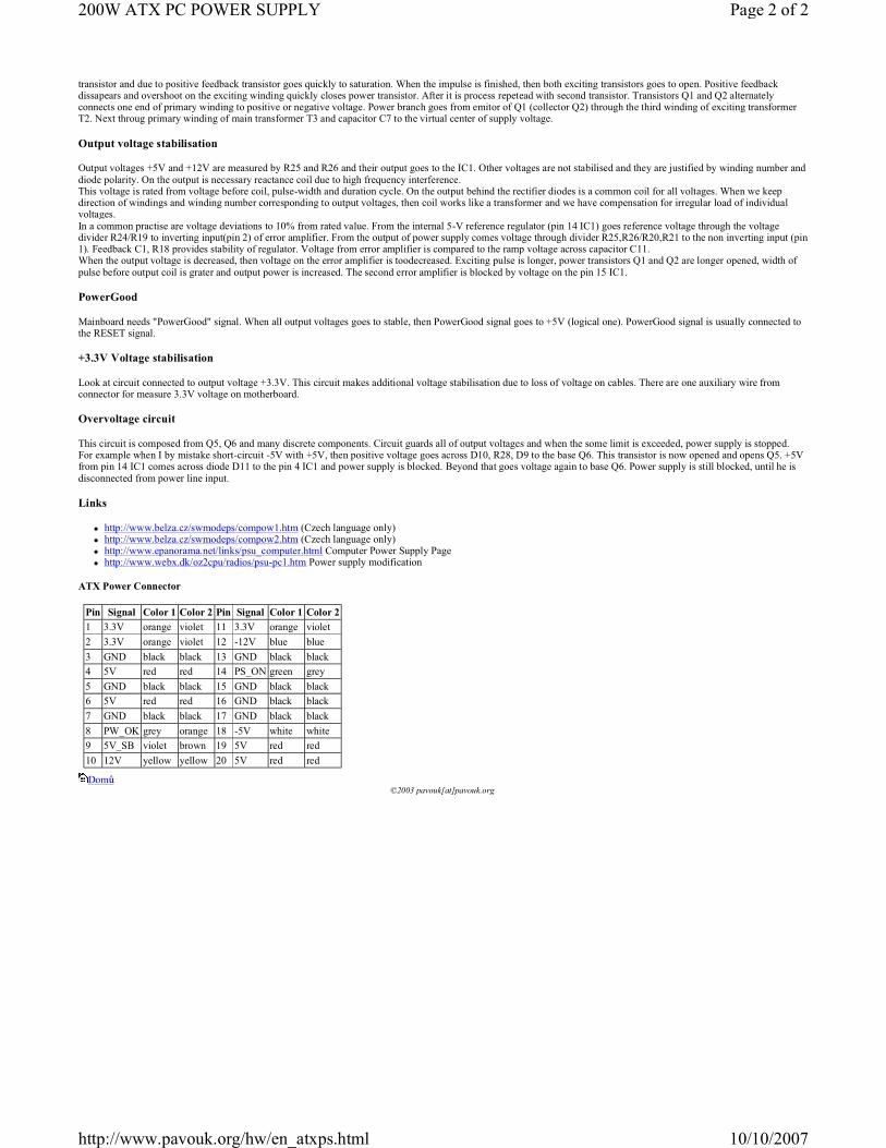
ATX Power Connector
Domů©2003 pavouk[at]pavouk.org
Pin Signal Color 1 Color 2 Pin Signal Color 1 Color 2
1 3.3V orange violet 11 3.3V orange violet
2 3.3V orange violet 12 -12V blue blue
3 GND black black 13 GND black black
4 5V red red 14 PS_ON green grey
5 GND black black 15 GND black black
6 5V red red 16 GND black black
7 GND black black 17 GND black black
8 PW_OK grey orange 18 -5V white white
9 5V_SB violet brown 19 5V red red
10 12V yellow yellow 20 5V red red
Page 2 of 2200W ATX PC POWER SUPPLY
10/10/2007http://www.pavouk.org/hw/en_atxps.html