the generalised constrained finite strip method for thin ...steel.org.au/media/file/r963.pdf ·...
TRANSCRIPT
school of ciVil engineering
research rePort r963august 2016
issn 1833-2781
the generalised constrained finite striP method for thin-Walled, Prismatic memBers under aPPlied shear
morgan a rendallgregory J hancocKKim Jr rasmussen

SCHOOL OF CIVIL ENGINEERING
THE GENERALISED CONSTRAINED FINITE STRIP METHOD FOR THIN-WALLED, PRISMATIC MEMBERS UNDER APPLIED SHEAR RESEARCH REPORT R963 MORGAN A RENDALL, GREGORY J HANCOCK, KIM JR RASMUSSEN August 2016 ISSN 1833-2781

The generalised constrained finite strip method for thin-walled prismatic members under applied shear
School of Civil Engineering Research Report R963 Page 2 The University of Sydney
Copyright Notice School of Civil Engineering, Research Report R963 The generalised constrained finite strip method for thin-walled prismatic members under applied shear Morgan A Rendall, Gregory J Hancock, Kim JR Rasmussen August 2016 ISSN 1833-2781 This publication may be redistributed freely in its entirety and in its original form without the consent of the copyright owner. Use of material contained in this publication in any other published works must be appropriately referenced, and, if necessary, permission sought from the author. Published by: School of Civil Engineering The University of Sydney Sydney NSW 2006 Australia This report and other Research Reports published by the School of Civil Engineering are available at http://sydney.edu.au/civil

The generalised constrained finite strip method for thin-walled prismatic members under applied shear
School of Civil Engineering Research Report R963 Page 3 The University of Sydney
ABSTRACT The constrained finite strip method (cFSM) is an extension of the semi-analytical finite strip method (SAFSM) of structural analysis of thin-walled members, where consideration of the displacement fields utilised and of various mechanical criteria allows constraint matrices to be formed. The application of these constraint matrices to the linear buckling eigenvalue problem of the SAFSM results in deformation fields that satisfy the considered criteria and, therefore, isolate particular modes. Through careful selection of the mechanical criteria, the deformation fields obtained may be restricted to particular buckling modes. This is referred to as modal decomposition. While the cFSM has been applied to modal decomposition of thin-walled, prismatic members under the action of longitudinal normal stresses, it has yet to be applied to such members under the action of shear stresses. Recent work using the SAFSM to analyse the buckling behaviour of thin-walled, prismatic members under applied shear stresses, notably by Hancock and Pham, has shown that the issues of potentially indistinct minima or multiple minima in the signature curve can occur under this loading, as they did for compression and bending. This paper briefly presents the derivation of a SAFSM that permits coupling between longitudinal series terms of sines and cosines and also considers membrane instability due both to shear stresses and transverse normal stresses. It then presents the application of the cFSM to such a finite strip and results are produced for members under shear stresses. While the results are presented for members with unrestrained ends (equivalent to infinitely long members with simply-supported ends), simplification via removal of the degrees of freedom not present in typical FSM formulations would allow finite length members with simply-supported ends to be analysed.
KEYWORDS Constrained finite strip method, semi-analytical finite strip method, shear buckling analysis, membrane instability

The generalised constrained finite strip method for thin-walled prismatic members under applied shear
School of Civil Engineering Research Report R963 Page 4 The University of Sydney
TABLE OF CONTENTS ABSTRACT .......................................................................................................................................................... 3 KEYWORDS ........................................................................................................................................................ 3 TABLE OF CONTENTS....................................................................................................................................... 4 1. Introduction ...................................................................................................................................................... 5 2. SAFSM for applied shear ................................................................................................................................ 5
2.1. Finite strip theory ...................................................................................................................................... 5 2.1.1. Linear buckling analysis ..................................................................................................................... 5 2.1.2. Displacement functions ...................................................................................................................... 6 2.1.3. Development of stiffness matrices ..................................................................................................... 8 2.1.4. Development of stability matrices ...................................................................................................... 9
2.1.4.1. Stability matrices for uniform transverse normal stress and uniform shear stress .................... 10 2.1.5. Assembly of global matrices for solution of the linear buckling eigenvalue problem ....................... 11
2.2. Examples of numerical analysis of sections in pure shear ..................................................................... 12 2.2.1. Lipped channel section ..................................................................................................................... 12 2.2.2. Rectangular hollow flange beam ...................................................................................................... 16
3. Application of the generalised cFSM ............................................................................................................. 19 3.1. Overview of the generalised cFSM [21, 22] ............................................................................................ 19
3.1.1. Fundamentals ................................................................................................................................... 19 3.1.2. Definitions of the modal spaces ....................................................................................................... 19 3.1.3. Formulation of constraint matrices ................................................................................................... 21
3.2. Application to an augmented displacement field .................................................................................... 21 3.3. Examples of modal decomposition and identification of sections in shear ............................................. 22
3.3.1. Lipped channel section in pure shear .............................................................................................. 22 3.3.2. Rectangular hollow flange beam in pure shear ................................................................................ 26
4. Conclusions ................................................................................................................................................... 29 5. Acknowledgements........................................................................................................................................ 29 6. References .................................................................................................................................................... 29 A. Explicit displacement and strain expressions for local stiffness and stability matrices ................................. 30 B. Cross-section orthogonal base vectors for a rectangular hollow flange beam ............................................. 31

The generalised constrained finite strip method for thin-walled prismatic members under applied shear
School of Civil Engineering Research Report R963 Page 5 The University of Sydney
1. INTRODUCTION The finite strip method (FSM) developed by Cheung [1] is a specialisation of the finite element method that utilises longitudinal regularity of the analysed member to reduce the dimension of the problem being analysed. First utilised for local buckling analysis of thin-walled members by Przemienicki [2], before being extended to other forms of buckling by Plank and Wittrick [3], the FSM has become an indispensable design tool thanks to its ability to generate a curve showing the critical elastic buckling stress of a section as a function of the buckling half-wavelength, when only a single longitudinal half-wavelength is considered; this is known as the signature curve of a section and is a concept that was popularised by Hancock [4]. The ubiquity of the FSM in the analysis and design of thin-walled, cold-formed steel members has only become more prevalent with the development of the Direct Strength Method (DSM) [5] which, in practice, predicts the ultimate strength of a member by considering the signature curve and the geometric and material properties of the section. Typically, this process involves taking the buckling stress values of the signature curve at its two minima as the critical stresses corresponding to local and distortional buckling, and using these in the DSM strength equations [6, 7]. However, there are many sections for which the signature curve may not have two minima, or may have more than one minimum for local or distortional buckling [8]. Further, the buckling modes at the lengths where the signature curve attains its minima may not be ‘pure’ local or distortional modes. These ambiguities in the signature curve prompted the development of the constrained finite strip method (cFSM) [9-11], which draws on the mechanical assumptions of Generalised Beam Theory (GBT) [12] in order to define pure global, distortional and local buckling modes. Application of the cFSM, available in the finite strip computer program CUFSM [13], then allows the critical buckling stresses of these pure local and distortional buckling modes to be determined. As the DSM is calibrated based on signature curves developed for the general (i.e. unconstrained) deformation field of the FSM, application of cFSM to the DSM and further development of the cFSM are fields of ongoing research [14-16].
Until recently, the DSM has only been applicable to members under longitudinal normal stresses, i.e. compression and/or bending; it has recently been extended to C-section members under shear [17]. As for the DSM for compression and bending, the DSM for shear requires knowledge of the signature curve of the section. The first finite strip capable of analysing members under shear stresses was that of Plank and Wittrick [3], which was recently revitalised by Hancock and Pham [18, 19] who applied the formulation to the buckling of C-sections under shear stresses. It should be noted that, as the FSM assumes longitudinal regularity, including stresses, the moment gradient necessary for a section under shear to be in equilibrium cannot be replicated and so the members analysed are under ‘pure’ shear. Their analysis, as well as subsequent analyses, such as of C-sections with longitudinal stiffeners [20], revealed signature curves that display many of the same ambiguities of those developed for members in compression and/or bending; i.e. indistinct minima and possible mode coupling. In light of this, applying the cFSM methodology to members in pure shear would prove useful, both as a theoretical tool for examining the buckling behaviour of such members and for assisting in further development of the DSM for shear. As the cFSM methodology is largely separate from the FSM to which it is applied, this paper will first present a finite strip that may be applied to members in a combined loading state, where all components of the Green-Lagrange in-plane strains are considered in formulating the stability matrices. Coupling between longitudinal series terms of different numbers of half-wavelengths is also permitted. Subsequently, the application of the cFSM methodology to this FSM will be elucidated, using the recently-developed generalised cFSM [21, 22].
2. SAFSM FOR APPLIED SHEAR
2.1. FINITE STRIP THEORY
2.1.1. Linear buckling analysis The linear buckling eigenvalue problem of the SAFSM is a second-order analysis formulated via the theorem of stationary potential energy. The total potential energy of the system is the sum of the internal elastic strain energy , which is obtained by evaluating the energy stored by the actions of the internal linear stresses in the linear strains , and the potential energy due to the externally applied stresses, which is obtained as the negative of the work of the applied stresses in the respective non-linear strains . This total potential energy is as shown in Eq. (2.1), where the integral is over the volume of the elements of the system

The generalised constrained finite strip method for thin-walled prismatic members under applied shear
School of Civil Engineering Research Report R963 Page 6 The University of Sydney
and the linear stresses and strains are related by , where is the relevant constitutive matrix for the problem at hand.
12
12
2.1
By relating the strains to the degrees of freedom of the system, the total potential energy may be rewritten as given in Eq. (2.2), where is the global elastic stiffness matrix of the system and is the global geometric stability matrix of the system, which scales linearly with the applied stresses and so is often written as a load factor multiplied by calculated for some reference stresses. Obtaining the stiffness and stability matrices for the SAFSM is described in the following sections.
12
12
12
2.2
By making the total potential energy of Eq. (2.2) stationary with respect to each degree of freedom, the classic linear buckling eigenvalue problem of the SAFSM is formulated and is as given in Eq. (2.3).
2.3
2.1.2. Displacement functions The first FSM able to analyse members under shear was that of Plank and Wittrick [3], who utilised complex degrees of freedom coupled with complex exponentials as defined by Eq. (2.4), where is proportional to the coordinate in the longitudinal direction and is the imaginary unit, to incorporate the phase-shift of displacements across the strip width that occurs for a member under shear stresses.
cos ∙ sin 2.4 The displacement fields were then defined as,
Re ∙ 2.5 where is the vector of transverse shape functions for the current displacement field, is the vector of corresponding complex degrees of freedom and ‘Re’ denotes the real part of its argument. When evaluating the longitudinal (warping) displacements, the argument of Eq. (2.5) was multiplied by to incorporate the out-of-phase nature of these displacements with respect to the transverse displacements. The utilised longitudinal functions correspond to a finite-length member with unrestrained ends or, equivalently, a member of infinite length with supported ends. Due to its complex mathematics, formulation of the stiffness and stability matrices depends on the identity given in Eq. (2.6), where and are vectors of equal length, is a square matrix of corresponding size and the bar denotes the complex conjugate. This identity has no direct analog for the case where the arguments of the two complex exponentials differ and so coupling between longitudinal series terms is not possible.
Re ∙ ∙ Re ∙ Re 2.6
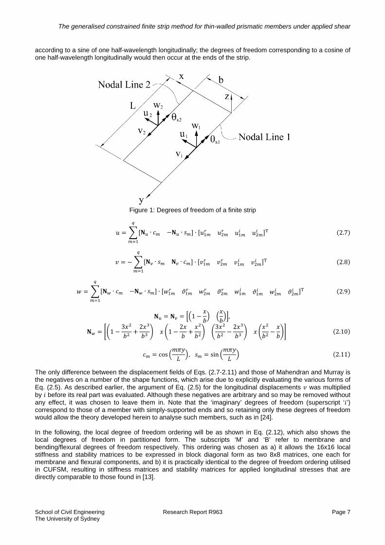
One method to potentially overcome this is to explicitly evaluate the ‘realness’ of Eq. (2.5) prior to formulating the stiffness and stability matrices. This was done by Mahendran and Murray [23] and resulted in a FSM with twice the usual number of degrees of freedom. Although this explicitly real displacement field of sines and cosines makes it possible to consider coupling between longitudinal series terms, Mahendran and Murray did not do so. The right-handed coordinate system and degrees of freedom utilised herein are as shown in Fig. 1; the corresponding displacement fields are as given in Eqs. (2.7-2.10), where and are as defined by Eq. (2.11) and so correspond to half-wavelengths along the member of length , the superscripts ‘ ’ and ‘ ’ refer to the real and imaginary components of the complex degrees of freedom of Eq. (2.5), and is the number of series terms considered. Note that, due to the sign of the shape functions used for the rotational degrees of freedom, a positive rotation about the longitudinal axis is defined by the left-hand rule. The degrees of freedom in Fig. 1 are all shown at the mid-length of the strip, which would correspond to longitudinal variation
The generalised constrained finite strip method for thin-walled prismatic members under applied shear
School of Civil Engineering Research Report R963 Page 7 The University of Sydney
according to a sine of one half-wavelength longitudinally; the degrees of freedom corresponding to a cosine of one half-wavelength longitudinally would then occur at the ends of the strip.
Figure 1: Degrees of freedom of a finite strip
∙ ∙ ∙ 2.7
∙ ∙ ∙ 2.8
∙ ∙ ∙ 2.9
1 ,
13 2
12 3 2
2.10
cos , sin 2.11
The only difference between the displacement fields of Eqs. (2.7-2.11) and those of Mahendran and Murray is the negatives on a number of the shape functions, which arise due to explicitly evaluating the various forms of Eq. (2.5). As described earlier, the argument of Eq. (2.5) for the longitudinal displacements was multiplied by before its real part was evaluated. Although these negatives are arbitrary and so may be removed without any effect, it was chosen to leave them in. Note that the ‘imaginary’ degrees of freedom (superscript ‘ ’) correspond to those of a member with simply-supported ends and so retaining only these degrees of freedom would allow the theory developed herein to analyse such members, such as in [24]. In the following, the local degree of freedom ordering will be as shown in Eq. (2.12), which also shows the local degrees of freedom in partitioned form. The subscripts ‘M’ and ‘B’ refer to membrane and bending/flexural degrees of freedom respectively. This ordering was chosen as a) it allows the 16x16 local stiffness and stability matrices to be expressed in block diagonal form as two 8x8 matrices, one each for membrane and flexural components, and b) it is practically identical to the degree of freedom ordering utilised in CUFSM, resulting in stiffness matrices and stability matrices for applied longitudinal stresses that are directly comparable to those found in [13].

The generalised constrained finite strip method for thin-walled prismatic members under applied shear
School of Civil Engineering Research Report R963 Page 8 The University of Sydney
2.12
2.1.3. Development of stiffness matrices The linear components of the transverse normal strain , longitudinal normal strain and in-plane shear strain , gathered as a single vector , may be split into membrane and bending components as in Eq. (2.13), of which the membrane components are calculated at the mid-line of the strip and the bending components follow Kirchoff thin-plate theory.
→
∙
∙
2 ∙
2.13
Interpreting the derivatives of Eq. (2.13) as a set of linear operators and substituting in Eqs. (2.7-2.9) using the degree of freedom ordering of Eq. (2.12) allows the linear strains to be expressed as,
∙ ∙ ∙ ∙ 2.14 where is the matrix of transverse and longitudinal shape functions, given in Appendix A. The 3x4 matrix components of on the right-hand side of Eq. (2.14) are also given, explicitly, in Appendix A. Comparing the terms for the internal strain energy in Eqs. (2.1) and (2.2) to the form of given in Eq. (2.14), the component of the local stiffness matrix that considers the internal elastic strain energy due to the stresses of the -th series term in the strains of the -th series term is,
∙ ∙ 2.15
where is the orthotropic constitutive matrix, given by Eq. (2.16), and is the strip volume.
00
0 0
/ 1 / 1 0
/ 1 / 1 00 0
2.16
The resultant membrane and bending components of the local stiffness matrix are then identical to a repetition of the same components of the local stiffness matrix of CUFSM (see Eqs. (9) and (10) of [13], respectively) on a 2x2 grid which defines the longitudinal functions to be integrated. This grid and its relationship to the notation of [13] are given in Eq. (2.17).
2.17
Excluding constants arising due to differentiation of the longitudinal functions utilised, the only longitudinal integrals that need be evaluated to fully define the stiffness matrix are those of the pairs of sines and cosines in Eq. (2.17). As only positive integer values of and are considered herein, the necessary values of these integrals are as given in Eq. (2.18).
2⁄ ,0,
;
∙2
, odd
0, even 2.18

The generalised constrained finite strip method for thin-walled prismatic members under applied shear
School of Civil Engineering Research Report R963 Page 9 The University of Sydney
The non-zero values of the integrals of and provide coupling between terms of different numbers of half-wavelengths longitudinally. It is this coupling that makes it possible to analyse members under shear with simply-supported ends [24].
2.1.4. Development of stability matrices The nonlinear strain components for the in-plane strains considered, calculated at the strip mid-line, are as shown in Eq. (2.19). In most FSM formulations, all of the nonlinear terms due to flexural displacements are included, while of the nonlinear terms due to membrane displacements, only those corresponding to the longitudinal normal strain are included. In Mahendran and Murray [23], for each strain, the terms associated with membrane displacements in the direction(s) of the strain were neglected. Herein, none of the nonlinear strain components will be neglected.
12
12
2.19
Noting that the displacement fields of Eqs. (2.7-2.9) may be written succinctly in the form of Eq. (2.20), it is apparent that the nonlinear strain terms of Eq. (2.19), excluding constants, may each be rewritten in the form of Eq. (2.21), where and are the relevant directions for the strain being considered; for the strains of Eq. (2.19), they may each be either or . The explicit forms of and are given by Eqs. (A2) and (A3) in Appendix A.
∙ 2.20
∙
∙
∙
2.21
Note that for the membrane shear strain, the nonlinear strain components for each displacement field are given by two components, as shown in Eq. (2.22), which are identical in scalar form, but are not when in vector form.
12
2.22
Applying Eq. (2.22) to Eq. (2.21) and then multiplying by the relevant applied stresses allows the work done by the applied stresses to be calculated, from which the local geometric stiffness matrix may be formed, which is given in Eq. (2.23). The permitted stress state on a strip is as shown in Fig. 2.

The generalised constrained finite strip method for thin-walled prismatic members under applied shear
School of Civil Engineering Research Report R963 Page 10 The University of Sydney
Figure 2: Permitted stress state on a strip
In the expression of Eq. (2.23), is an index for the total different stresses applied to the strip, is the applied stress to which and are the coordinate directions of the corresponding nonlinear strain components, and is a factor that takes a value of 1/2 when and is unity otherwise, in order to allow the different nonlinear strain components of Eq. (2.19) to all be included in Eq. (2.23).
∙∙ ∙
∙ ∙
2.23
As with the local stiffness matrix, the local stability matrix has uncoupled membrane and bending components. Each of these components consists of two terms in Eq. (2.23), which are transposes of one another if the indices and are also swapped. That is,
∙ → ∙ 2.24
∙ → ∙ 2.24
Note that if , then the two terms are equal to one another for each component. As with the local stiffness matrix, the membrane and bending components of the local stability matrix for applied longitudinal normal stresses are of identical form as the same components of the local stability matrix for applied longitudinal stresses of CUFSM (see Eqs. (11) and (12) of [13], respectively), repeated on the 2x2 grid of Eq. (2.17). The necessary values of the longitudinal integrals are again as given by Eq. (2.18).
2.1.4.1. Stability matrices for uniform transverse normal stress and uniform shear stress For an applied uniform transverse normal stress , the relevant nonlinear strain coordinate directions are
. By letting represent the longitudinal function of half-wavelengths longitudinally, as in [13], and letting ⁄ , the membrane component of the local stability matrix for transverse normal stresses may be expressed as a 4x4 matrix, given in Eq. (2.25), replicated on the 2x2 grid of Eq. (2.17). Eq. (2.25) was produced by noting that the constituent terms in Eq. (2.24a) of the membrane component are equal and that
1/2. The bending component may be similarly derived. Due to the form of (see Eq. (A3) in Appendix A), the bending component of the local stability matrix for transverse normal stresses may be expressed as a 4x4 matrix, given in Eq. (2.26), replicated on the 2x2 grid of Eq. (2.17).

The generalised constrained finite strip method for thin-walled prismatic members under applied shear
School of Civil Engineering Research Report R963 Page 11 The University of Sydney
0 0
0 0
0 0
0 0
2.25
65
110
65
110
110
215
110 30
65
110
65
110
110 30
110
215
2.26
For an applied uniform shear stress , the relevant nonlinear strain coordinate directions are and
(this assignment is arbitrary). The expressions on either side of Eqs. (2.24a) and (2.24b) are not equivalent in this case, so the associated local stability matrix components are somewhat more complicated. The membrane and bending components of the local stability matrix for uniform shear stress may be expressed as 4x4 matrices, given in Eqs. (2.27) and (2.28) respectively, replicated on the 2x2 grid of Eq. (2.17).
2
0 0
0 0
0 0
0 0
2.27
12 10
12 10
100
10 6012 10
12 10
10 60 100
2.28
The shear stability matrices are notably different to the stiffness and other stability matrices in that, when
, its non-zero quadrants as defined by Eq. (2.17) are the off-diagonal quadrants, rather than those on the main diagonal, and vice versa when is odd. This explicitly shows the coupling between components of different phases (i.e. sines and cosines) that is required to incorporate the phase-shift of displacements across the strip width when under applied shear. Note that the bending component of the shear stability matrix is nearly skew-symmetric; the integrated pairs of longitudinal functions along the main diagonal sum to zero in all cases except when and is odd, in which case they sum to 2.
2.1.5. Assembly of global matrices for solution of the linear buckling eigenvalue problem Once the local stiffness and stability matrices are assembled for a strip, they are transformed to global coordinates by application of the transformation matrix , given in Eq. (2.29), where cos and sin , where is the angle about the longitudinal axis between the global coordinate system and the local strip coordinate system, taken as positive when clockwise. (Note that the longitudinal axes of the two coordinate systems are parallel). Transforming a local matrix to global coordinates is achieved by .
,diag 1 1 1 1diag 0 0 0 0
2.29
The generalised constrained finite strip method for thin-walled prismatic members under applied shear
School of Civil Engineering Research Report R963 Page 12 The University of Sydney
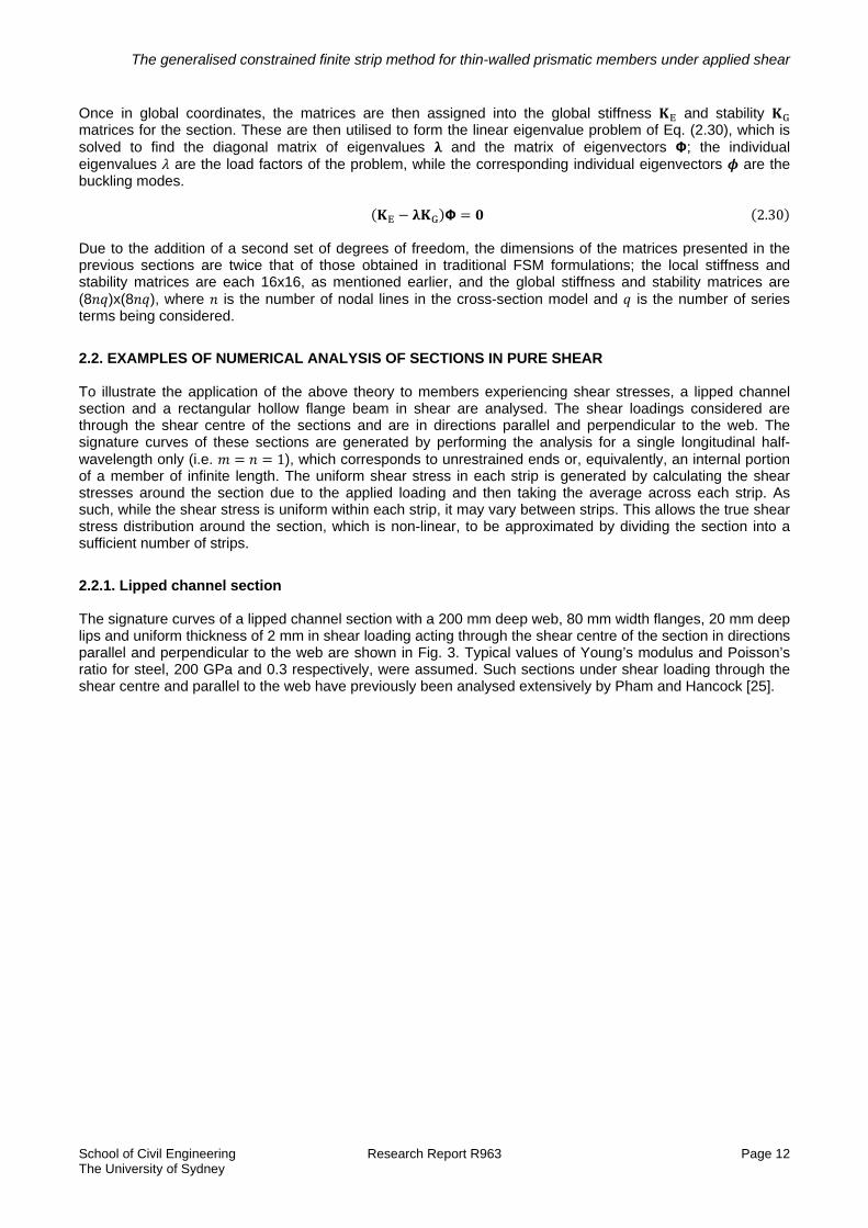
Once in global coordinates, the matrices are then assigned into the global stiffness and stability matrices for the section. These are then utilised to form the linear eigenvalue problem of Eq. (2.30), which is solved to find the diagonal matrix of eigenvalues and the matrix of eigenvectors ; the individual eigenvalues are the load factors of the problem, while the corresponding individual eigenvectors are the buckling modes.
2.30 Due to the addition of a second set of degrees of freedom, the dimensions of the matrices presented in the previous sections are twice that of those obtained in traditional FSM formulations; the local stiffness and stability matrices are each 16x16, as mentioned earlier, and the global stiffness and stability matrices are (8 )x(8 ), where is the number of nodal lines in the cross-section model and is the number of series terms being considered.
2.2. EXAMPLES OF NUMERICAL ANALYSIS OF SECTIONS IN PURE SHEAR To illustrate the application of the above theory to members experiencing shear stresses, a lipped channel section and a rectangular hollow flange beam in shear are analysed. The shear loadings considered are through the shear centre of the sections and are in directions parallel and perpendicular to the web. The signature curves of these sections are generated by performing the analysis for a single longitudinal half-wavelength only (i.e. 1), which corresponds to unrestrained ends or, equivalently, an internal portion of a member of infinite length. The uniform shear stress in each strip is generated by calculating the shear stresses around the section due to the applied loading and then taking the average across each strip. As such, while the shear stress is uniform within each strip, it may vary between strips. This allows the true shear stress distribution around the section, which is non-linear, to be approximated by dividing the section into a sufficient number of strips.
2.2.1. Lipped channel section The signature curves of a lipped channel section with a 200 mm deep web, 80 mm width flanges, 20 mm deep lips and uniform thickness of 2 mm in shear loading acting through the shear centre of the section in directions parallel and perpendicular to the web are shown in Fig. 3. Typical values of Young’s modulus and Poisson’s ratio for steel, 200 GPa and 0.3 respectively, were assumed. Such sections under shear loading through the shear centre and parallel to the web have previously been analysed extensively by Pham and Hancock [25].

The generalised constrained finite strip method for thin-walled prismatic members under applied shear
School of Civil Engineering Research Report R963 Page 13 The University of Sydney
Figure 3: Signature curves for a lipped channel section in shear
As noted in [25], the signature curve for the section loaded in shear parallel to the web drops to a minimum at a half-wavelength of 200 mm, where the buckling mode is local in nature, then increases and peaks, with a corresponding transition through to distortional buckling, and then begins to decrease again as the mode switches to a flexural-torsional one. These modes are shown in Figs. 4(a-c) for the section analysed in Fig. 3 in shear parallel to the web. The modes shown are at half-wavelengths of a) 200 mm, corresponding to the minimum in the signature curve; b) 900 mm and c) 3500 mm. In each of these modes, the phase-shift of displacements as one moves around the section is evident. As mentioned in the Introduction, the member is in a fictitious state of ‘pure’ shear, where moment gradient (or indeed any moment) is not present along the member, and so the modes at longer buckling half-wavelengths are somewhat artificial.
Figure 4: Buckling modes of a lipped channel section in shear loading parallel to the web, at half-wavelengths
of a) 200 mm, b) 900 mm and c) 3500 mm

The generalised constrained finite strip method for thin-walled prismatic members under applied shear
School of Civil Engineering Research Report R963 Page 14 The University of Sydney
To delve further into the buckling modes consider that, as the SAFSM utilised produces buckling modes that vary longitudinally according to the combination of a sine and a cosine, the cross-sectional variation of the buckling mode at the ends of the half-wavelength is purely due to the cosine, while that at the middle is purely due to the sine. This suggests that it is possible to examine the cross-sectional variation of the buckling mode at these locations to visualise the two modes (sine and cosine) that constitute the full buckling mode. However, as the utilised harmonic functions correspond to examining an internal portion of an infinitely long member, it is clear that the exact portion of the member which the eigenvectors correspond to is arbitrary. That is, the buckling modes may be phase-shifted up and down the length of the member without any effect on the eigenvalues/load factors and so the cross-sectional variations at the ends and middle are not unique. Despite this, it is clear from the nature of sines and cosines (i.e. they are identical except for a phase-shift of 2⁄ , or one quarter-wavelength) that the two modes that constitute the full buckling mode may always be
found one quarter-wavelength apart, or half of the buckling half-wavelength. To illustrate this, consider Fig. 5, which displays the buckling mode of a lipped channel in shear parallel to the web at a buckling half-wavelength of 2000 mm. At two cross-sections, denoted by “a)” and “b)” respectively, the cross-section deformation relative to the undeformed section is also shown; these sections are exactly one quarter-wavelength apart. These two sections show very different deformations, corresponding to symmetric distortional and flexural-torsional modes respectively; the overall mode might then be classified as a coupled distortional-flexural-torsional mode.
Figure 5: Buckling mode of a lipped channel in shear parallel to the web at a half-wavelength of 2000 mm and
‘pure’ cross-section deformations separated by one quarter-wavelength The buckling behaviour of the lipped channel in shear perpendicular to the web is quite different to that of the section in shear parallel to the web. The signature curve indicates that the maximum stress in the section at buckling is significantly greater at all half-wavelengths with the shear applied perpendicular, rather than parallel, to the web. The shape of the curve is also different, with a flattening of the curve around half-wavelengths of 200-300 mm, but no minimum forming, and a similar flattening, with a minimum just forming at a half-wavelength of 900 mm, before the mode suddenly switches to include torsional deformations at a half-wavelength of 1400 mm. That the mode switch is sudden is indicated by the discontinuity in the slope of the signature curve at this half-wavelength. These differences may be partially explained by examining the shear stress distributions around the section for each loading; these are shown in Fig. 6, where the abscissa represents the distance around the centreline of the section, and the sign convention is such that a positive shear stress would generate a clockwise moment about the centroid of the section.

The generalised constrained finite strip method for thin-walled prismatic members under applied shear
School of Civil Engineering Research Report R963 Page 15 The University of Sydney
Figure 6: Shear stress distribution around centreline of a lipped channel section in shear
From Fig. 6 it is clear that, for a given magnitude of shear load, the stresses in the web are significantly higher when the load is applied parallel to the web, with the maximum shear stress in the section occurring at the middle of the web, whereas the maximum shear stress in the section occurs in the flanges when the load is perpendicular to the web. Further, the shear stresses through the depth of the web are all of the same sign when the loading is parallel to the web, whereas they are of opposite signs in the upper and lower halves of the web when the loading is perpendicular to the web. Since the plate flexural behaviour of the web dominates that for the section, it is then clear that it is significantly easier for the section to buckle in local modes at shorter half-wavelengths when the shear load is applied parallel rather than perpendicular to the web, to the point that a minimum forms on the signature curve. For distortional modes at moderate half-wavelengths, the stresses in the flanges and lips play a significant role and so the higher shear stresses in these elements when the section is loaded in shear perpendicular to the web allows the signature curve to provide a clear ‘dip’ at these half-wavelengths. No such drop in critical maximum stress is observed when the section is loaded in shear parallel to the web, likely due to the shear stresses in the flanges and lips being much smaller than those in the web. The greater critical maximum stresses persist for the section loaded in shear perpendicular to the web and this continues into the long half-wavelength range, perhaps due to the stresses in the top and bottom halves of the section being of opposite signs. Examples of the buckling modes obtained at short, moderate and long half-wavelengths for the lipped channel loaded in shear perpendicular to the web are shown in Figs. 7(a-c).

The generalised constrained finite strip method for thin-walled prismatic members under applied shear
School of Civil Engineering Research Report R963 Page 16 The University of Sydney
Figure 7: Buckling modes of a lipped channel section in shear loading perpendicular to the web, at half-
wavelengths of a) 200 mm, b) 900 mm and c) 3500 mm While the flexural-torsional mode is similar to the case of shear loading parallel to the web in Fig. 6c, the local and distortional modes are different. This is likely due to the symmetric shear stress distribution around the section when loaded in shear perpendicular to the web, which would then tend to favour buckling modes in which the phase shift of displacements around the section is also symmetric. An example of this symmetry may easily be examined in the separate sine and cosine vectors that constitute the overall buckling mode, as shown in Fig.8 for the local buckling mode of Fig. 7a.
Figure 8: Component buckling mode vectors of a lipped channel in shear loading perpendicular to the web at
a half-wavelength of 200 mm
2.2.2. Rectangular hollow flange beam The signature curves of a rectangular hollow flange beam in shear loading acting through the shear centre of the section in directions parallel and perpendicular to the web are shown in Fig. 9. The geometric and material properties of the section are identical to those of the lipped channel analysed in Figs. 3-8, except that additional flat elements are added horizontally between the tips of the lips and the web to form closed tubular flanges. Similar hollow flange sections in shear have been analysed by Keerthan and Mahendran [26, 27] using the finite element method, but have yet to be analysed using the SAFSM.

The generalised constrained finite strip method for thin-walled prismatic members under applied shear
School of Civil Engineering Research Report R963 Page 17 The University of Sydney
Figure 9: Signature curves of a rectangular hollow flange beam in shear
It is clear from Fig. 9 that the addition of the elements to form closed tubular flanges has a significant effect on the shear behaviour of the section. Except at very short half-wavelengths, the signature curves display significantly higher critical shear stresses than the corresponding curves of Fig. 3. Due to the reduction of the clear width of the web and also the greater restraint offered by the tubes, the minima in the signature curves occur at shorter half-wavelengths of 140 mm and 120 mm for shear loading parallel and perpendicular to the web respectively. The buckling modes at these minima are shown in Figs. 10(a-c), where ‘parallel’ and ‘perpendicular’ refer to the shear loading directions with respect to the web and Fig. 10c is simply that of Fig. 10b phase-shifted by one quarter-wavelength to be a closer representation of Fig. 7a. (Remember that the ends of the analysed members are unrestrained, so this phase-shift does not invalidate the mode). From Figs. 10(a-c) it is clear that the modes are qualitatively similar to those of the lipped channel (see Figs. 4a and 7a), although with significantly less deformation of the tubular flanges due to their greater torsional stiffness. This increased torsional stiffness is also the cause of the much more pronounced peaks in the signature curves at moderate half-wavelengths, where the buckling modes are mixed local-distortional modes. Since distortional buckling is characterised by significant flange deformation, the increased stiffness of the tubular flanges results in significantly greater critical stresses for distortional buckling.

The generalised constrained finite strip method for thin-walled prismatic members under applied shear
School of Civil Engineering Research Report R963 Page 18 The University of Sydney
Figure 10: Local buckling modes of a rectangular hollow flange beam at minimum on signature curves
To provide further comparison of the effects of closing the flanges to form tubes, the buckling modes of the rectangular hollow flange beam in shear loading parallel and perpendicular to the web are shown in Figs. 11(a-c) and 12(a-c), respectively, for the half-wavelengths utilised in Figs. 4(a-c) and 7(a-c).
Figure 11: Buckling modes of a rectangular hollow flange beam in shear loading parallel to the web, at half-
wavelengths of a) 200 mm, b) 900 mm and c) 3500 mm
Figure 12: Buckling modes of a rectangular hollow flange beam in shear loading perpendicular to the web, at
half-wavelengths of a) 200 mm, b) 900 mm and c) 3500 mm The modes of Figs. 11a and 12a are largely the same as those of Figs. 4a and 7a, but there are a number of differences in the modes at longer half-wavelengths when compared to those of the lipped channel section.
The generalised constrained finite strip method for thin-walled prismatic members under applied shear
School of Civil Engineering Research Report R963 Page 19 The University of Sydney
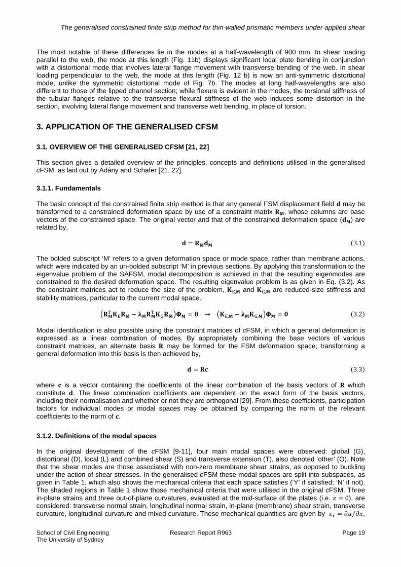
The most notable of these differences lie in the modes at a half-wavelength of 900 mm. In shear loading parallel to the web, the mode at this length (Fig. 11b) displays significant local plate bending in conjunction with a distortional mode that involves lateral flange movement with transverse bending of the web. In shear loading perpendicular to the web, the mode at this length (Fig. 12 b) is now an anti-symmetric distortional mode, unlike the symmetric distortional mode of Fig. 7b. The modes at long half-wavelengths are also different to those of the lipped channel section; while flexure is evident in the modes, the torsional stiffness of the tubular flanges relative to the transverse flexural stiffness of the web induces some distortion in the section, involving lateral flange movement and transverse web bending, in place of torsion.
3. APPLICATION OF THE GENERALISED CFSM
3.1. OVERVIEW OF THE GENERALISED CFSM [21, 22] This section gives a detailed overview of the principles, concepts and definitions utilised in the generalised cFSM, as laid out by Ádány and Schafer [21, 22].
3.1.1. Fundamentals The basic concept of the constrained finite strip method is that any general FSM displacement field may be transformed to a constrained deformation space by use of a constraint matrix , whose columns are base vectors of the constrained space. The original vector and that of the constrained deformation space ( ) are related by,
3.1 The bolded subscript ‘M’ refers to a given deformation space or mode space, rather than membrane actions, which were indicated by an un-bolded subscript ‘M’ in previous sections. By applying this transformation to the eigenvalue problem of the SAFSM, modal decomposition is achieved in that the resulting eigenmodes are constrained to the desired deformation space. The resulting eigenvalue problem is as given in Eq. (3.2). As the constraint matrices act to reduce the size of the problem, , and , are reduced-size stiffness and stability matrices, particular to the current modal space.
→ , , 3.2 Modal identification is also possible using the constraint matrices of cFSM, in which a general deformation is expressed as a linear combination of modes. By appropriately combining the base vectors of various constraint matrices, an alternate basis may be formed for the FSM deformation space; transforming a general deformation into this basis is then achieved by,
3.3 where is a vector containing the coefficients of the linear combination of the basis vectors of which constitute . The linear combination coefficients are dependent on the exact form of the basis vectors, including their normalisation and whether or not they are orthogonal [29]. From these coefficients, participation factors for individual modes or modal spaces may be obtained by comparing the norm of the relevant coefficients to the norm of .
3.1.2. Definitions of the modal spaces In the original development of the cFSM [9-11], four main modal spaces were observed: global (G), distortional (D), local (L) and combined shear (S) and transverse extension (T), also denoted ‘other’ (O). Note that the shear modes are those associated with non-zero membrane shear strains, as opposed to buckling under the action of shear stresses. In the generalised cFSM these modal spaces are split into subspaces, as given in Table 1, which also shows the mechanical criteria that each space satisfies (‘Y’ if satisfied; ‘N’ if not). The shaded regions in Table 1 show those mechanical criteria that were utilised in the original cFSM. Three in-plane strains and three out-of-plane curvatures, evaluated at the mid-surface of the plates (i.e. 0), are considered: transverse normal strain, longitudinal normal strain, in-plane (membrane) shear strain, transverse curvature, longitudinal curvature and mixed curvature. These mechanical quantities are given by ⁄ ,

The generalised constrained finite strip method for thin-walled prismatic members under applied shear
School of Civil Engineering Research Report R963 Page 20 The University of Sydney
⁄ , ⁄ ⁄ , ⁄ , ⁄ and ⁄ respectively. Also considered is whether or not the cross-section satisfies transverse equilibrium, as indicated by the ‘eq.’ row in Table 1.
Table 1: Mechanical criteria for mode classes in generalised cFSM [21]
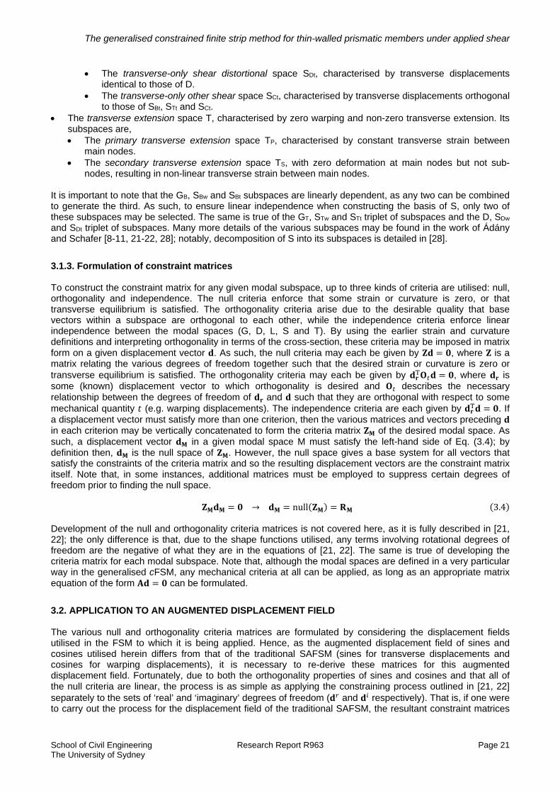
As some understanding of the various spaces that will be utilised is necessary for appropriate application of the cFSM, each space and subspace is now briefly described. First, a key distinction is to be made between the modes of primary and secondary spaces. The deformations of primary modes are fully defined by the degrees of freedom of the main nodes, or those at the junctions or ends of the plates comprising the section. Deformations of secondary modes are defined by the degrees of freedom of sub-nodes, or those that exist within a flat plate. With these definitions, it is worth noting that the G and D (sub)spaces are primary spaces. The base vectors of a rectangular hollow flange beam for each modal space are given in Appendix B, in the same order as the spaces are presented here. The global space G, which involves rigid-body transverse displacements and associated warping
displacements such that there is no transverse extension nor any in-plane shear strains. Its subspaces are, The global axial space GA, defined by uniform warping displacements only. The global bending space GB, defined by rigid-body transverse displacements with an associated
linear warping distribution over the section and null rotations. The global torsion space GT, defined by rigid-body torsion of the section with associated warping
displacements. This mode does not exist if the section has closed parts, as torsion without shear strains is impossible in such sections [28].
The distortional space D, where transverse extension and in-plane shear strains are again null, but the section may distort in such a way that transverse equilibrium is satisfied.
The local space L, where transverse extension, in-plane shear strains and warping displacements are null; deformations are similar to local-plate buckling. Its subspaces are, The primary local space LP, with mode deformations as though no sub-nodes exist. The secondary local space LS, with zero deformation at main nodes but not sub-nodes.
The shear space S, characterised by non-null in-plane shear strains. Its subspaces can be divided into two overarching types. The warping-only shear space Sw, where only warping displacements are non-zero. The subspaces
that fall under this category are, The warping-only shear bending space SBw, characterised by warping displacements identical to
those of GB. The warping-only shear torsion space STw, characterised by warping displacements identical to
those of GT. If GT does not exist, neither does STw. The warping-only shear distortional space SDw, characterised by warping displacements identical
to those of D. The warping-only other shear space SCw, characterised by linear warping distributions between
main nodes, orthogonal to those of SBw, STw and SCw. The secondary (warping-only) shear space SS, characterised by non-linear warping
displacements between main nodes. The transverse-only shear space St, where transverse displacements are non-zero while warping
displacements are zero. The subspaces in this category are, The transverse-only shear bending space SBt, characterised by rigid-body transverse
displacements identical to those of GB. The transverse-only shear torsion space STt, characterised by rigid-body transverse
displacements identical to those of GT. This mode always exists, even if GT does not.
The generalised constrained finite strip method for thin-walled prismatic members under applied shear
School of Civil Engineering Research Report R963 Page 21 The University of Sydney
The transverse-only shear distortional space SDt, characterised by transverse displacements identical to those of D.
The transverse-only other shear space SCt, characterised by transverse displacements orthogonal to those of SBt, STt and SCt.
The transverse extension space T, characterised by zero warping and non-zero transverse extension. Its subspaces are, The primary transverse extension space TP, characterised by constant transverse strain between
main nodes. The secondary transverse extension space TS, with zero deformation at main nodes but not sub-
nodes, resulting in non-linear transverse strain between main nodes. It is important to note that the GB, SBw and SBt subspaces are linearly dependent, as any two can be combined to generate the third. As such, to ensure linear independence when constructing the basis of S, only two of these subspaces may be selected. The same is true of the GT, STw and STt triplet of subspaces and the D, SDw and SDt triplet of subspaces. Many more details of the various subspaces may be found in the work of Ádány and Schafer [8-11, 21-22, 28]; notably, decomposition of S into its subspaces is detailed in [28].
3.1.3. Formulation of constraint matrices To construct the constraint matrix for any given modal subspace, up to three kinds of criteria are utilised: null, orthogonality and independence. The null criteria enforce that some strain or curvature is zero, or that transverse equilibrium is satisfied. The orthogonality criteria arise due to the desirable quality that base vectors within a subspace are orthogonal to each other, while the independence criteria enforce linear independence between the modal spaces (G, D, L, S and T). By using the earlier strain and curvature definitions and interpreting orthogonality in terms of the cross-section, these criteria may be imposed in matrix form on a given displacement vector . As such, the null criteria may each be given by , where is a matrix relating the various degrees of freedom together such that the desired strain or curvature is zero or transverse equilibrium is satisfied. The orthogonality criteria may each be given by , where is some (known) displacement vector to which orthogonality is desired and describes the necessary relationship between the degrees of freedom of and such that they are orthogonal with respect to some mechanical quantity (e.g. warping displacements). The independence criteria are each given by . If a displacement vector must satisfy more than one criterion, then the various matrices and vectors preceding in each criterion may be vertically concatenated to form the criteria matrix of the desired modal space. As such, a displacement vector in a given modal space M must satisfy the left-hand side of Eq. (3.4); by definition then, is the null space of . However, the null space gives a base system for all vectors that satisfy the constraints of the criteria matrix and so the resulting displacement vectors are the constraint matrix itself. Note that, in some instances, additional matrices must be employed to suppress certain degrees of freedom prior to finding the null space.
→ null 3.4 Development of the null and orthogonality criteria matrices is not covered here, as it is fully described in [21, 22]; the only difference is that, due to the shape functions utilised, any terms involving rotational degrees of freedom are the negative of what they are in the equations of [21, 22]. The same is true of developing the criteria matrix for each modal subspace. Note that, although the modal spaces are defined in a very particular way in the generalised cFSM, any mechanical criteria at all can be applied, as long as an appropriate matrix equation of the form can be formulated.
3.2. APPLICATION TO AN AUGMENTED DISPLACEMENT FIELD The various null and orthogonality criteria matrices are formulated by considering the displacement fields utilised in the FSM to which it is being applied. Hence, as the augmented displacement field of sines and cosines utilised herein differs from that of the traditional SAFSM (sines for transverse displacements and cosines for warping displacements), it is necessary to re-derive these matrices for this augmented displacement field. Fortunately, due to both the orthogonality properties of sines and cosines and that all of the null criteria are linear, the process is as simple as applying the constraining process outlined in [21, 22] separately to the sets of ‘real’ and ‘imaginary’ degrees of freedom ( and respectively). That is, if one were to carry out the process for the displacement field of the traditional SAFSM, the resultant constraint matrices

The generalised constrained finite strip method for thin-walled prismatic members under applied shear
School of Civil Engineering Research Report R963 Page 22 The University of Sydney
may be denoted , as all of will be zero and will contain all of the degrees of freedom of the base vectors. Consequently, the constraint matrix of the augmented displacement field is simply,
3.5 where is identical to except that the values of and are swapped. The same is also true of multiple series terms, again due to orthogonality between sines and cosines of different numbers of half-wavelengths; the constraint matrices for a given number of half-wavelengths do not influence nor are influenced by the presence of terms with different number of half-wavelengths. This leads to the constraint matrices of the augmented displacement field with multiple series terms being of the form,
diag … 3.6 where the subscript refers to the number of the half-wavelength considered. Clearly, the order of the columns in the constraint matrices is arbitrary, but keeping them grouped is desirable. While it is easy, mathematically, to show the above for most of the null criteria, the case of transverse equilibrium warrants a more intuitive explanation, which is now laid out. Consider an augmented displacement field of sines and cosines that satisfies transverse equilibrium at all points longitudinally. No matter the number of half-wavelengths being considered, there will be points where one of the sine or cosine is zero yet the other is non-zero. At these points, the non-zero component of the displacement field must then be in transverse equilibrium, regardless of the other component. For this component however, only the amplitude of transverse displacements varies along the length, not their relative values; hence, this component must satisfy transverse equilibrium at every point longitudinally, independently of the other component, for which the same is also true. As such, transverse equilibrium of the augmented displacement field, like the other null criteria, is enforced by applying the corresponding null criteria matrix separately for the ‘real’ and ‘imaginary’ degrees of freedom.
3.3. EXAMPLES OF MODAL DECOMPOSITION AND IDENTIFICATION OF SECTIONS IN SHEAR To illustrate the application of the generalised cFSM, the same lipped channel section and rectangular hollow flange beam analysed previously are again considered. For each section and type of loading modal solutions, generated by solving the appropriately constrained reduced eigenvalue problem, are generated and compared to the unconstrained FSM solutions. These results are presented for a single half-wavelength longitudinally (i.e. 1). Modal identification results are also presented and the modal participations so found are linked to the buckling modes that occur.
3.3.1. Lipped channel section in pure shear The pure modal solutions for the G, D and L modal spaces, generated by cFSM for a single buckling half-wavelength longitudinally, are shown in Fig. 13 for the lipped channel section analysed previously, along with the FSM signature curves. For each loading, the local modal solution is practically identical to the FSM signature curve at short half-wavelengths, with significant deviations only appearing after the buckling half-wavelength exceeds the section web depth, while at very long half-wavelengths the critical maximum stress of the global modal solution rapidly decreases until it is practically coincident with the FSM signature curve. The most significant deviations from the FSM signature curve occur for the distortional modal solutions. For shear loading parallel to the web it is likely that, as mentioned previously, the lower stresses in the flanges render it more difficult for the section to buckle in a purely distortional manner, resulting in the distortional solution sitting significantly above the signature curve. For the shear load applied perpendicular to the web, the elements of the reduced geometric stability matrix are almost singular relative to those of the reduced elastic stiffness matrix, resulting in ludicrously large critical maximum stresses. This suggests that the shear stress distribution for shear loading through the shear centre of the section and perpendicular to the web does negligible work in the pure distortional modes of the lipped channel section. In contrast, the work done by this stress distribution in combined local-distortional modes is significant, as suggested by the presence of significant local buckling deformations in the ‘distortional’ buckling mode of Fig. 7b.

The generalised constrained finite strip method for thin-walled prismatic members under applied shear
School of Civil Engineering Research Report R963 Page 23 The University of Sydney
Figure 13: FSM and modal cFSM signature curves for a lipped channel section in shear
That local buckling deformations are still significant at moderate half-wavelengths under this shear stress distribution may be examined by producing modal solutions for the combined distortional and local modal space (D + L), as shown in Fig. 14. Comparing the D + L modal solutions to both the FSM signature curves and the local modal solutions of Fig. 13 reveal that the combination of distortional and local deformations plays a significant role in the unconstrained buckling behaviour of a lipped channel in shear loading perpendicular to the web, as expected. In contrast, the same comparison carried out for the shear loading parallel to the web reveals that the addition of the distortional deformations to the local deformations has a relatively minor effect on the modal solution.

The generalised constrained finite strip method for thin-walled prismatic members under applied shear
School of Civil Engineering Research Report R963 Page 24 The University of Sydney
Figure 14: FSM and D + L cFSM signature curves for a lipped channel section in shear
A number of prior observations, including those just made on the degree to which distortional deformations affect the unconstrained buckling behaviour, may be made more explicit by carrying out modal identification. In carrying out the identification process, base vectors were normalised such that the greatest magnitude of any degree of freedom was unity (vector norm) and the participation results obtained for the individual mode vectors were combined into participation for the five modal spaces using the -norm (Euclidean norm). These choices for normalisation and norm were made based on the work of Li et. Al [29]. As mentioned previously, three triplets of subspaces are linearly dependent, meaning only two may be selected from each triplet; here, the shear-free subspaces (e.g. D) and the corresponding transverse-only shear subspaces (e.g. SDt) were utilised. The identification results are given in Fig. 15.

The generalised constrained finite strip method for thin-walled prismatic members under applied shear
School of Civil Engineering Research Report R963 Page 25 The University of Sydney
Figure 15: Modal identification results for a lipped channel section in shear
The modal identification results for shear loading applied parallel to the web are fairly typical of open sections analysed using cFSM. At short half-wavelengths, the results indicate essentially pure local participation, which smoothly but rapidly transitions to more distortional participation as the half-wavelength is increased. At moderate half-wavelengths the distortional participation peaks at ~67%, with small contributions of both local and global modes. As the half-wavelength increases further, distortional participation drops off sharply as the modal participation becomes essentially purely global in nature. Shear and transverse extension participation are essentially negligible at all analysed half-wavelengths. The results for shear loading applied perpendicular to the web are qualitatively similar to those for parallel loading, but there are a few noticeable differences. At very short half-wavelengths, there is a small dip in the local participation as there exist very small amounts of shear and transverse extension participation. The peak in the distortional mode participation is greater at ~75%, but occurs at the same half-wavelength as for the parallel shear loading. At a half-wavelength of ~1400 mm, there are sharp jumps in the modal participation results; these indicate a sudden mode switch which, as mentioned earlier, is also indicated by the discontinuity in the slope of the signature curve at this half-wavelength. Fig. 16 shows the buckling modes a) before the switch and b) after the switch. The most obvious change is of the distortional mode, which switches from symmetric to anti-symmetric; the second mode involved changes from a local mode to a torsional mode, resulting in the drop in local participation and rise in global participation evident in Fig. 15.
Figure 16: Mode switch of a lipped channel section in shear loading perpendicular to the web, between half-
wavelengths of a) 1402 mm and b) 1404 mm In both cases of loading it is important to note that, despite the distortional modal solutions of Fig. 13 lying significantly higher than the unconstrained FSM solutions, the distortional participation is still significant over a large range of half-wavelengths due to the critical modes at those half-wavelengths being a combined distortional and local/global mode.

The generalised constrained finite strip method for thin-walled prismatic members under applied shear
School of Civil Engineering Research Report R963 Page 26 The University of Sydney
3.3.2. Rectangular hollow flange beam in pure shear The pure modal solutions for the G + STt, D and L modal spaces, generated by cFSM for a single buckling half-wavelength longitudinally, are shown in Fig. 17 for the rectangular hollow flange beam analysed previously, along with the FSM signature curves. As the section has closed loops, neither GT nor STw exist, hence STt has been combined with the G modal space (which consists of only GA and GB here) to ensure that overall torsion of the section is included in the analysis, as was done in [21, 22].
Figure 17: FSM and modal cFSM signature curves for a rectangular hollow flange beam in shear
As with the lipped channel section, the local modal solution is practically coincident with the FSM signature curve at short half-wavelengths, with deviations appearing as moderate half-wavelengths are approached. The distortional solutions again display significantly higher critical stresses than the FSM signature curves, however that for shear loading perpendicular to the web now displays more typical behaviour. This is because the closed loops, by eliminating the GT mode, gives rise to a new distortional mode in its place; this mode may be deemed a lateral-distortional mode and is shown in Fig. 18 along with the usual symmetric and anti-symmetric distortional modes. This lateral-distortional mode then couples with the anti-symmetric distortional mode to produce elements of the geometric stability matrix that are, in this case, within a few orders of magnitude of the elements of the elastic stiffness matrix. In the case of shear loading parallel to the web, the lateral-distortional mode couples with the symmetric distortional mode although, in each loading case, the lateral-distortional mode is the dominant one.

The generalised constrained finite strip method for thin-walled prismatic members under applied shear
School of Civil Engineering Research Report R963 Page 27 The University of Sydney
Figure 18: cFSM distortional modes of a rectangular hollow flange beam
It is also interesting, yet unsurprising, to note that the loss of the GT mode means that its ‘intended’ warping profile is then found in the lateral-distortional mode; this is shown in Fig. 19, which displays the warping profiles of the GT mode of a lipped channel section and of the lateral-distortional (DLat) mode for the rectangular hollow flange beam.
Figure 19: Warping profiles of GT for a lipped channel and DLat for a rectangular hollow flange beam
As the half-wavelength becomes very long, the modal solutions of the combined global and transverse-only shear torsion space approach the FSM signature curves, but do not coincide with them, instead levelling out somewhat above them. As mentioned previously, this is due to the torsional stiffness of the tubular flanges relative to the transverse flexural stiffness of the web inducing some distortion in the section. There are also significant shear strains in these buckling modes and so to have the modal solution become nearly coincident with the FSM signature curve at very long half-wavelengths requires consideration of a combined space consisting of the global, distortional and primary shear modes. This is also borne out by the modal identification results, shown in Fig. 20. Note that, while the STt mode was coupled with the global modes in producing the modal solutions of Fig. 17, it is classified as a shear mode for the purposes of modal identification, as the global modes are strictly free of in-plane shear strains.

The generalised constrained finite strip method for thin-walled prismatic members under applied shear
School of Civil Engineering Research Report R963 Page 28 The University of Sydney
Figure 20: Modal identification results for a rectangular hollow flange beam in shear
The results for the shear loading parallel to the web are as expected at short half-wavelengths, with essentially pure local participation. As the half-wavelength increases, distortional participation increases and peaks at a longer half-wavelength than for the lipped channel section, before dropping off again but still being quite significant at very long half-wavelengths, with ~10% participation. Unlike the lipped channel, the presence of the tubular flanges results in the development of significant shear strains and hence the shear mode participation is evident over a wide range of half-wavelengths. It is especially noticeable at long half-wavelengths, where the STt mode comes into play. The dip in the shear mode participation, which coincides with the peak in the distortional participation, likely indicates a switch in which shear modes are taking part in the overall buckling mode. While the global mode participation does increase as the half-wavelength becomes very long, it is less marked than for the lipped channel section due to the significant distortional and shear participation at these half-wavelengths. The results for shear loading perpendicular to the web display a more complicated buckling behaviour; at very short half-wavelengths the buckling mode is purely local in nature, as expected. As the half-wavelength increases, there is a marked drop in the local participation as distortional participation rises to a small peak. The local participation is then essentially constant over a small range of half-wavelengths, where the increasing half-wavelength allows the symmetric distortional mode to be replaced by a flexural mode, hence the swap from distortional to global participation. Between half-wavelengths of 828 mm and 830 mm, for which the corresponding buckling modes are shown in Fig. 21, there is a mode switch from a combined local-flexural mode to a distortional mode involving significant shear strains and a significantly lesser amount of local participation.
Figure 21: Mode switch of a rectangular hollow flange beam in shear loading perpendicular to the web,
between half-wavelengths of a) 828 mm and b) 830 mm

The generalised constrained finite strip method for thin-walled prismatic members under applied shear
School of Civil Engineering Research Report R963 Page 29 The University of Sydney
4. CONCLUSIONS A semi-analytical finite strip method (SAFSM) for analysis of members in general loading including shear has been presented, utilising an augmented displacement field of sines and cosines to allow the phase-shift of displacements due to shear stresses to be incorporated. All of the Green’s strains were included in formulating the geometric stability matrix, where the nonlinear membrane shear strains and nonlinear membrane transverse strains are usually neglected in the formulation. Signature curves were produced for a lipped channel section and a similarly-sized rectangular hollow flange beam in shear loading parallel and perpendicular to the web, for which typical buckling modes were shown and elucidated. Further, it was made clear that the resulting overall mode consists of two separate modes, one each for the sine and the cosine, which need not be remotely similar. The generalised constrained finite strip method was then summarised and its application to the developed SAFSM was elucidated. Modal decomposition and identification were then performed for the sections analysed previously and were used to further explore the nature of the buckling modes obtained by the SAFSM, including the presence of sudden mode switches.
5. ACKNOWLEDGEMENTS The authors are grateful for the work of Prof. Ben Schafer, Assoc. Prof. Sándor Ádány, Assoc. Prof. Zhanjie Li and others in developing the open-source finite strip software CUFSM [13], whose plotting codes were utilised to produce the cross-sections displayed in this paper. Thanks are also extended to Mr. Song Hong Pham and Mr. Van Vinh Nguyen for providing the graphics program used to generate the 3D buckling modes in this paper.
6. REFERENCES [1] Y.K. Cheung, Finite strip method in the analysis of elastic plates with two opposite ends, ICE Proc. 40 (1) (1968) 1–7. [2] J.S. Przemieniecki, Finite element structural analysis of local instability, AIAA J. 11 (1) (1973) 33-39. [3] R.J Plank, W.H. Wittrick, Buckling under combined loading of thin, flat-walled structures by a complex finite strip method, Int. J. Numer. Meth. Eng. 8 (2) (1974) 323-339. [4] G.J. Hancock, Local, distortional, and lateral buckling of I-beams, ASCE J. Struct. Div. 104 (11) (1978) 1787-1798. [5] B.W. Schafer, T. Peköz, Direct strength prediction of cold-formed steel members using numerical elastic buckling solutions, Proc. 14th Int. Spec. Conf. on Cold-Formed Steel Struct. St. Louis, Missouri (1998) 69-76. [6] American Iron and Steel Institute (AISI), North American specification for the design of cold-formed steel structural members [2012 Ed.], AISI S100-2012, 2012. [7] Standards Australia, AS/NZS 4600, Cold-Formed Steel Structures, Standards Australia/Standards New Zealand, 2005. [8] S. Ádány, Buckling mode classification of members with open thin-walled cross-sections by using the finite strip method, Research Report, Johns Hopkins University (2004). [9] S. Ádány, B.W. Schafer, Buckling mode decomposition of single-branched open cross-section members via finite strip method: Derivation, Thin-Walled Struct. 44 (5) (2006) 563-584. [10] S. Ádány, B.W. Schafer, Buckling mode decomposition of single-branched open cross-section members via finite strip method: Applications and examples, Thin-Walled Struct. 44 (5) (2006) 585-600. [11] S. Ádány, B.W. Schafer, A full modal decomposition of thin-walled, single-branched open cross-section members via the constrained finite strip method, J. Constr. Steel Res. 64 (1) (2008) 12-29. [12] R. Schardt, Verallgameinerte Technische Biegetheorie, Springer-Verlag, Berlin, 1989 (in German).

The generalised constrained finite strip method for thin-walled prismatic members under applied shear
School of Civil Engineering Research Report R963 Page 30 The University of Sydney
[13] Z. Li, B.W. Schafer, Buckling analysis of cold-formed steel members with general boundary conditions using CUFSM: conventional and constrained finite strip methods, Proc. Int. Spec. Conf. on Cold-Formed Steel Struct., St. Louis, Missouri (2010). [14] Z. Beregszászi, S. Ádány, Application of the constrained finite strip method for the buckling design of cold-formed steel columns and beams via the direct strength method, Comput. Struct. 89 (21-22) (2011) 2020-2027. [15] Z. Li, B.W. Schafer, Application of the finite strip method in cold-formed steel member design, J. Constr. Steel Res. 66 (8-9) (2010) 971-980. [16] S. Ádány, Z. Beregszászi, Modal decomposition for thin-walled members with rounded corners: An extension to cFSM by using elastic corner elements, Proc. 8th Int. Conf. on Adv. in Steel Struct. (2015). [17] C.H. Pham, G.J. Hancock, Direct strength design of cold-formed C-sections for shear and combined actions, ASCE J. Struct. Eng. 138 (6) (2012) 759-768. [18] G.J. Hancock, C.H. Pham, Direct Strength Method of design for shear of cold-formed channels based on a shear signature curve, Proc. 21st Int. Spec. Conf. on Cold-Formed Steel Struct. (2012). [19] G.J. Hancock, C.H. Pham, A signature curve for cold-formed channel sections in pure shear, Research Report R919, The University of Sydney (2011). [20] S.H. Pham, C.H. Pham, and G.J Hancock, Direct strength method of design for shear including sections with longitudinal web stiffeners, Thin-Walled Struct. 81 (2014) 19-28. [21] S. Ádány, B.W. Schafer, Generalized constrained finite strip method for thin-walled members with arbitrary cross-section: Primary modes, Thin-Walled Struct. 84 (2014) 150-169. [22] S. Ádány, B.W. Schafer, Generalized constrained finite strip method for thin-walled members with arbitrary cross-section: Secondary modes, orthogonality, examples, Thin-Walled Struct. 84 (2014) 123-133. [23] M. Mahendran, N.W. Murray, Elastic buckling analysis of ideal thin-walled structures under combined loading using a finite strip method, Thin-Walled Struct. 4 (5) (1986) 329-362. [24] G.J. Hancock, C.H. Pham, Shear buckling of channel sections with simply supported ends using the Semi-Analytical Finite Strip Method, Thin-Walled Struct. 71 (2013) 72-80. [25] C.H. Pham, G.J. Hancock, Shear buckling of channels using the semi-analytical and spline finite strip methods, J. Constr. Steel Res. 90 (2013) 42-48. [26] P. Keerthan, M. Mahendran, Elastic buckling characteristics of LiteSteel beams, J. Constr. Steel Res. 66 (11) (2010) 1309-1319. [27] P. Keerthan, M. Mahendran, Improved shear design rules of cold-formed steel beams, Eng. Struct. 99 (2015) 603-615. [28] S. Ádány, Decomposition of in-plane shear in thin-walled members, Thin-Walled Struct. 73 (2013) 27-38. [29] Z. Li, M.T. Hanna, S. Ádány, B.W. Schafer, Impact of basis, orthogonalization and normalization on the constrained Finite Strip Method for stability solutions of open thin-walled members, Thin-Walled Struct. 49 (9) (2011) 1108-1122.
A. EXPLICIT DISPLACEMENT AND STRAIN EXPRESSIONS FOR LOCAL STIFFNESS AND STABILITY MATRICES Due to the assumption of small displacements, the membrane and flexural local displacements of a strip are uncoupled. As such, all three displacement fields may be expressed at once as in Eq. (A1), where the longitudinal sinusoids have been absorbed into the matrix .

The generalised constrained finite strip method for thin-walled prismatic members under applied shear
School of Civil Engineering Research Report R963 Page 31 The University of Sydney
∙ ∙ A1
Utilising the expressions of Eqs. (2.10) and (2.11), the forms of and are,
,1 0 0
0 1 0,
1 0 0
0 1 0 A2
∙ ∙ A3
Using Eqs. (A2) and (A3), the components of the strain matrix of Eq. (2.14) (reproduced as Eq. (A4)) are as given by Eqs. (A5-A8). The longitudinal functions have been expressed using the substitutions of Eq. (2.11). A prime represents differentiation with respect to the longitudinal direction.
∙ ∙ ∙ ∙ A4
10
10
0 1 0
11 1
A5
1
01
0
0 1 0
11 1
A6
6 12 4 6 6 12 6 2
13 2
12 3 2
12 122
8 6 12 12 6 4
A7
6 12 4 6 6 12 6 2
13 2
12 3 2
12 122
8 6 12 12 6 4
A8
B. CROSS-SECTION ORTHOGONAL BASE VECTORS FOR A RECTANGULAR HOLLOW FLANGE BEAM The base vectors for a rectangular hollow flange beam are illustrated in Figs. B1-B7. Within each modal subspace, the vectors have been orthogonalised with respect to various cross-section mechanical quantities, using the process outlined in [22]. As the cross-sectional variation of the base vectors for the sines and

The generalised constrained finite strip method for thin-walled prismatic members under applied shear
School of Civil Engineering Research Report R963 Page 32 The University of Sydney
cosines are identical up to a factor, only one set need be illustrated. A section with a coarse mesh is used for visualisation; the only effect of using fewer sub-nodes is that each secondary space has a smaller number of base vectors. There are a few things to note in Figs. B1-B7. The first is that the modes GA and GT are not shown; GA is not illustrated as it corresponds to uniform warping displacements and null transverse displacements, while GT does not exist for this section, due to the presence of closed loops. Further, the warping and transverse displacement profiles of Fig. B1, if taken in isolation from one another, correspond to the equivalent warping-only shear and transverse-only shear base vectors, due to the linear independence explained at the end of Section 3.1.2. Hence the primary Sw and St spaces both have seven base vectors; five each from Fig. B1 and two each from Fig. B4. Finally, note that the base vectors for the TP space, given in Fig. B6, differ from those in [22]; this is due to encountering multiplicative eigenvalues in the orthogonalisation process, which prevents the modes being orthogonalised.
Figure B1: Warping (top) and transverse (bottom) displacement profiles of orthogonal base vectors for the GB
and D spaces

The generalised constrained finite strip method for thin-walled prismatic members under applied shear
School of Civil Engineering Research Report R963 Page 33 The University of Sydney
Figure B2: Orthogonal base vectors for the LP space
Figure B3: Orthogonal base vectors for the LS space
Figure B4: Remaining base vectors for the SP space
The generalised constrained finite strip method for thin-walled prismatic members under applied shear
School of Civil Engineering Research Report R963 Page 34 The University of Sydney
Figure B5: Orthogonal base vectors for the SS space
Figure B6: Base vectors (non-orthogonal) for the TP space
Figure B7: Orthogonal base vectors for the TS space