th international command and control research and ... · creating c4isr applications with...
TRANSCRIPT

Creating C4ISR Applications with Composable, Component-Based Architectures Ken Graves, Darius Miller, and Laurence Bernstein
CHI Systems, Inc. 11838 Bernardo Plaza Court, Suite 102A
San Diego, CA 92128
Submission to 10th International Command and Control Research and Technology Symposium (ICCRTS)
Mr. Graves holds a B.S. in Nuclear Engineering from the US Military Academy, 1978, and has over 26 years experience in technical C4I-related systems development and evaluation, operations and safety assessment. He has performed a wide variety of RDT&E, operational, and training tasks for the US Navy, US Marine Corps, US Army, and Special Operations Forces. He currently directs advanced research, development, and production of tactical C4ISR systems for five Army programs and one Marine Corps program. Prior to joining CHI Systems, Mr. Graves served in the Army as an airborne artillery battalion S3 (operations officer), Corps Artillery G3 Planner, Brigade and Battalion Fire Support Officer, chief of operations for a heavy weapons training complex, twice as commander of combat units, and in various positions with special operations forces. Mr. Miller holds an M.S. in Computer Science from the University of Delaware, 1995, and has over 14 years of extensive software design and implementation experience in the M&S, C4ISR, and artificial intelligence domains. He was the principal architect of the C3Core architecture. Currently he is the technical project lead of the CDAS and CDAS FFW programs, each of which is a large scale C++ project with hundreds of classes. He was also the PI for the ARDEC Reference Architecture Tool Support (RATS) Phase II SBIR program, which is a highly abstracted set of software architecture design tools designed for building modular, component-based, “plug and play” software systems. Mr. Miller has extensive expertise in network and algorithm design, optimization and simulation, using these capabilities to develop the C3Core terrain component which is currently fielded with the US Marine Corps. Mr. Bernstein holds a B.A. in Computer Science from the University of California, San Diego, 1988, and has over 17 years of extensive software design and implementation experience in the M&S, imagery analysis, and artificial intelligence domains. Currently he is the head of CHI Systems’ C3Core architecture team, with primary responsibility for architecture and software development for the CDAS and CDAS FFW programs. He is also the project manager for the Intermediate Staging Base Decision Aid (ISBDA), which involves the development of simulated robotic system behaviors for a number of robotic resupply systems, as well as combat systems. This project is being performed in support of the FCS program. Prior to joining CHI Systems, Mr. Bernstein was the president of Triptyk Software, where he was also the lead designer and developer for a suite of applications used by the Callaway Golf Company to analyze launch parameters of golf clubs and balls for equipment research and development. He also led software development and production of a number of image processing and financial services applications, and developed one of the leading commercially used compression algorithms.

Page 1 of 16
Creating C4ISR Applications with Composable, Component-Based Architectures Ken Graves, Darius Miller, and Laurence Bernstein
CHI Systems Inc.
ABSTRACT A critical problem in filling C4ISR technology gaps in future or existing systems is the
inability to reconfigure existing “stovepipe” C4ISR architectures to test and prototype solutions. Existing C4ISR systems, such as those in the Army Battle Command System (ABCS) are inflexible, and costly and time consuming to alter in attempts to find solutions. To solve this problem, CHI Systems has developed a revolutionary new architecture called C3Core, for developing custom, composable, flexible C4ISR configurations and applications. C3Core uses a repository of “plug and play” components which can be selected and packaged by a developer, or in some cases users, to provide tailored C4ISR applications to suit different needs. There are minimal dependencies between components. All components interact with each other via the use of a small backplane which registers component services and provides a transport mechanism. C3Core provides a common toolbox framework for insertion, removal, and improvement of components to allow developers to package different C4ISR application configurations for different needs using a core repository of building blocks. Application flexibility ranges from Future Combat System (FCS) Unit of Action (UA) level fires and effects coordination, vehicle level route planning, and soldier-level situational awareness and fire distribution.
1. INTRODUCTION
In the current and projected warfighting environment, it is extremely difficult to provide leaders and soldiers with C4ISR applications which are tailored to the exact needs of their environment. Most existing C4ISR systems such as ABCS were designed for traditional warfighting scenarios such as “Fulda Gap.” Our soldiers now face asymmetric threats in many different environments; these threats and environments were not even envisioned when our current C4ISR systems were developed, and it is now proving very difficult to modify these systems to cope with the threats.
The C4ISR systems envisioned for the Future Combat System (FCS) and Future Force Warrior (FFW) programs will take into account many of the threats and environments which we are seeing in today’s conflicts. However, these systems are many years away, and will still require the flexibility to be quickly adapted to new threats and environments. Given that some portions of the current ABCS systems seem to have a chance of continuing into the Future Force C4ISR architecture, it remains to be seen whether that architecture will be agile enough to be quickly and cost effectively tailored to meet unexpected or unforeseen requirements.
C3Core was developed by CHI Systems to meet the C4ISR community’s need to provide rapidly tailorable, scaleable and cost effective C4ISR solutions. C3Core is a composable, extensible, scaleable, and reconfigurable architecture of reusable software components designed to support rapid application design, development, testing, and deployment of advanced concepts in C4ISR, networked fires and effects, wearable computing, and embedded computing. C3Core is not a specific software application, but rather a set of tools and reusable components for developing applications in an evolutionary and spiral development manner.
Component reuse within C3Core leads to great cost effectiveness, as we can develop once and field multiple times. At the heart of C3Core is a small set of backplane services which enable a large set of independent, highly leveled and refactored components to interact with one

Page 2 of 16
another and with an (extensible) set of C2 databases and knowledge-bases. The plug-in architecture of C3Core facilitates rapid spiral development of prototype and production-level command and control systems in support of network-centric warfare. C3Core has been employed to create applications for multiple US Army weapons systems and programs including FCS, FFW, and the USMC’s Command and Control Personal Computer (C2PC). A custom application is developed by plugging a specific set of components and data/knowledge bases (possibly with customizations or extensions) into the 'core services' backplane.
C3Core fills an extremely valuable and unique role as a development framework for future technology. There are few, if any, existing systems which can be configured to fill the many different C4ISR needs of commanders, staff officers, small unit leaders, and soldiers for future force organizations such as the Unit of Action (UA). C3Core has the capability to provide flexible, prototypical functionality of the different C4ISR capabilities which are required from the individual soldier or vehicle up to FCS UA commanders and staffs, and across the various domains such as fires and effects, logistics, situational awareness, and others. It serves as a proving ground for developing new software components that can fill technology gaps in existing C4ISR systems or in future force C4ISR systems.
A series of brief examples are given immediately below illustrating how C3Core has been used to enable rapid development and evolution of a range of command and control systems. In the remainder of the paper, the C3Core architecture is described in more depth, and a detailed case study is presented.
1.1 Illustrative Examples A long-term and successful illustration of C3Core’s technology development role is the
Combat Decision Aid Suite (CDAS), an $11M program for the US Army Armaments Research, Development, & Engineering Command (ARDEC). CDAS is a testbed for developing new software components that can fill technology gaps in existing and planned Army C4ISR systems. Over the last 4 years, the C3Core team at CHI Systems has been delivering regular 6-month spiral prototypes of CDAS along a growing number of development threads (e.g., for netted fires, logistics, common operating picture) and numerous shorter spirals for concept experiments at the Depth & Simultaneous Attack Battle Lab (D&SABL), Fort Sill; Unit of Action Maneuver Battle Lab (UAMBL), Fort Knox; and the Dismounted Battlespace Battle Lab (DBBL) at Fort Benning (CHI Systems, Inc., 2004). CDAS is, however, only one possible implementation of the C3Core architecture; many different implementations have been developed, using different transport mechanisms, software languages, and development environments. Each implementation has the basic composable, component-based, plug and play nature of the C3Core architecture.
To develop components that fill technology gaps, C3Core is configured to mimic most functions of a legacy system at appropriate levels of fidelity, and the new components are then designed, developed, and tested within the simulated legacy system environment. When a new component is proven in simulation, it is then tested within a battle lab environment to determine suitability and maturity. Successful testing in a battle lab environment can then lead to the component being determined ready to offer as Government Furnished Software for improving legacy systems with technology gaps, or for use in developmental future force systems.
The API structure and the real-time nature of the core services allow C3Core to function as a developmental testbed during rapid, spiral development. Functionality that is needed but which is not present in any development spiral can be simulated or emulated by a legacy system and integrated through a standard C3Core API. When the functionality is later developed in a future

Page 3 of 16
spiral as a true functional component, that component can replace the simulation/ emulation with a simple plug-and-play operation (which can be made at run time). This approach has been used many times to provide rapid reconfiguration and modification in support of concept experiments at battle labs and operational demonstrations. This process has resulted in numerous transition successes for C3Core-based applications and component, including:
• The C3Core Terrain component has been fielded as government furnished software since 2001 with the USMC’s Command and Control Personal Computer (C2PC) application; C2PC is a DII COE system and is the USMC’s primary C4ISR system. Annual upgrades to this component are performed for the USMC.
• The C3Core Weapon System Knowledge Base component is being fielded as government furnished software in C2PC beginning in FY05 to allow display of US and other country weapon system characteristics.
• The C3Core Fires component is currently being provided as government furnished software to the Future Force Warrior (FFW) Lead System Integrator for inclusion in FFW software with scheduled fielding in 2008 (CHI Systems & ARDEC, 2003).
• The C3Core “Typical Package” plus the symbology component is currently being packaged for emergency deployment of radio direction finding capability for Improvised Explosive Device (IED) transmitters. From initial requirements definition to delivery required less than 6 weeks, with a prototype delivered for testing after only two weeks.
• C3Core is currently beginning the process of transitioning portions of the terrain services component as GFE to use in AFATDS for determination of terrain-based flight routes for NLOS-LS Precision Attack Missiles.
• C3Core currently supplies the networked fires and effects capability for the Army RDECOM’s Modeling Architecture Technology, Research and Experimentation (MATREX) program.
• C3Core has been used in 4 Future Fires Command and Control experiments at the D&SABL, Fort Sill; a Future Combat Command & Control experiment at the UAMBL, Fort Knox; and also has 50 installations at the DBBL at Fort Benning.
C3Core implementations demonstrated a high degree of scalability and flexibility in a number of FCS/FFW battle lab experiments where different C3Core implementations were used by UA-level commanders and staffs down to individual FFW soldiers. The same C3Core components used on UA-level workstations quickly and easily scaled for use in individual soldier and vehicle systems. In these experiments, different plug and play variants of C3Core were used by a variety of role players to include:
• Brigade Commander, Intelligence, Operations, and Plans Officers • Artillery Forward Observer • Fires and Effects Control Officers and NCOs • Logistics Officers and NCOs • Mortar Platoon Leaders and Artillery Battery Commanders • RSTA team leader • FFW soldier, squad leader, and platoon leader
Each role player could configure C3Core for their own needs by tailoring the toolsets available to them within the application. While performing their duties, each role player could communicate and collaborate with other role players in a common environment for information

Page 4 of 16
sharing, such that logisticians, fire supporters, maneuver commanders, and intelligence personnel had a common operational picture that facilitated rapid planning and tactical execution. The architecture eliminated the “stovepipe” communications and software architecture problems encountered with the current Army Battle Command System (ABCS) applications.
Figures 1 and 2 show the dramatic range in flexibility of C3Core configurations for battle lab experiments. Figure 1 illustrates how C3Core (configured as Future Fires Decision Support System) provided tailored C4ISR tools for eighteen different role players during an experiment that tested possible battle staff configurations for fires and effects management across a FCS UA (Depth & Simultaneous Attack Battle Lab, 1999). In Figure 2, the same C3Core architecture is configured with different plug-and-play components as a soldier-mounted situational awareness and fire support application for the FFW program. This configuration was used in recent user evaluations of C3Core FFW capabilities at the DBBL at Fort Benning, Georgia (Coleman & Graves, 2003 and 2004).
HQ 63A HQ 63B ECC
MVR Bn 1 MVR Bn 2 MVR Bn 3 4 Firing Batteries
SoftwareEngineering
CSS Officer
OPSSergeant
Deputy CO Plans
Plans Officer
Force Prot. Officer
OPSOfficer
Deputy CO OPS
CSS Officer
Lar
ge S
cree
n M
onito
r
Lar
ge S
cree
n M
onito
r
Larg
e Scr
een
Mon
itor
IntelOfficer
TargetingOfficer
Fire Control 1 & 2
Brigade Commander
DISNetwork
Battalion ECC
Battalion ECC
Battalion ECC
Battery Commander
DSABL & CHI Systems
Figure 1. C3Core Used in Eighteen Different C4ISR Roles During
Future Fires Command and Control Experiment.

Page 5 of 16
Figure 2. Soldiers Using Tailored C3Core Components for
Collaborative Planning During FFW CDAS User Evaluation.
C3Core can be used to create many different applications in different domains. Figure 3 summarizes the cross-platform, multi-domain composability and portability of the architecture. These applications span a range of areas that require C4ISR capabilities, from Homeland Security to man- and vehicle-mounted applications in several different operating systems.
Figure 3. Multiple Variations of C3Core for Different Domains.

Page 6 of 16
2. ARCHITECTURE
The C3Core architecture is described below, beginning with its fundamental organization as a service-based infrastructure populated with plug-and-play sets of independent, functional components. The key component sets available within C3Core are then discussed. 2.1 Plug-in concept
C3Core is an architecture of reusable, plugin components and services, which are used in
conjunction with a “core backplane” to facilitate rapid development of conceptual and production-level decision aids in support of FCS and FFW C4ISR research, experimentation and development. Rapid tailoring is a key feature. For example, a custom C3Core application, which interfaces with various sensors and performs sensor fusion to allow the location of Improvised Explosive Device (IED) factories was recently developed. Only six weeks were required to analyze the requirement, build a new sensor interface component, package existing components, test, and deliver the package for acceptance testing and deployment. In an even more extreme example, C3Core was used to create a custom application for presentation to the Border Patrol Search, Trauma, and Rescue (BORSTAR) team in San Diego. That custom package was built in 12 hours using existing components, with no software development or recompile required.
Some components in the C3Core architecture, such as the map server component, are common to most packages. These common components and others from within the C3Core repository of components can be used, along with the core backplane to rapidly tailor various decision aiding applications for multiple uses. The plugin architecture of C3Core is designed to provide composable, cross-platform support from embedded weapons systems through Brigade level command in domains such as Tactical/Technical Fire Control, Netted Fires, Common Operational Picture, Terrain and Mobility Analysis, Collaborative Planning, Operations, Intelligence and Analysis, and Logistics Monitoring. Components may be used to create C3Core-based applications, or components may be exported to other applications after they have matured.
By using the concept of a plugin architecture, C3Core furthers the concept of software reuse, and hence cost effectiveness, for multiple applications. The architecture features a number of decision aiding components, such as terrain services, weapon system knowledge, tactical symbology and weapon-target pairing, which can be reused in other architectures or applications.
For instance, by selecting various components from the repository such as map server, C3 Database, Logistics Monitoring and weapon-target pairing, the architecture can be used to configure a decision aiding application for artillery tactical fire control for use on a desktop computer. By using other components, a decision aiding application can be built for mortar fire direction on a palm device or a tailored situation awareness and networked fires application on a wearable PC for dismounted operations. This concept is illustrated in Figure 4.
More detailed discussion of the technical aspects of the architecture is contained Appendix 1.

Page 7 of 16
Figure 4. Conceptual View of C3Core Plug and Play Application Building.
2.2 Major C3Core Components The C3Core architecture and component repository consists of 230 plugins and components.
Generally, plugins are small, and provide incremental functionality to one of the major components. For example, the C3Core map server component in its most basic form consists of 5 plugins. These plugins provide basic georeferencing capabilities, the ability to zoom and pan on a map, and ability to display a single map type known as GSHHS. The addition of other plugins allow the user to access more sophisticated map functionality, such as the ability to read georeferenced satellite imagery, National Geospatial-Intelligence Agency (NGA) raster, vector and elevation maps, US Geographic Service raster maps, and various commercial map formats. The most capable variant of the map server would have 24 plugins, and provide functionality similar to that of the Commercial Joint Mapping Tool Kit.

Page 8 of 16
Figure 5. C3Core’s Levelized, Component-Based Architecture.
The C3Core architecture is highly levelized; within any level of the architecture, no component is dependent on any component which falls lower in the architecture as shown in Figure 5. Levelized packages, as shown in the figure, contain the components in the level above them, and the components within that level. At the “Core Package” level, the only component supplied in a package would be the core services that allow component registration and transport. At the “Minimal Package” level, the three components in the minimal package, plus the “Core Package” would be supplied. The same pattern holds true for the “Interface Package” and “Typical Package” levels. Other components outside the main levels, such as Terrain, Map_Pack, Simulation, and Fires can be added into the packages at the appropriate levels as shown in the figure to produce different and more sophisticated variants of a basic C4ISR application. The following sections briefly discuss the most significant of the components within the C3Core architecture. Most of the major components have APIs and Software Development Kits (SDKs).
2.2.1 Fires Component The fires component provides all required functions associated with the selection of
appropriate weapon systems to engage one or more targets. A number of plugins comprise this component in order to provide a complete fires package which encompasses the entire chain of events from designating a target for attack (forward observer) to tactical fire control through sending of the fire missions to individual weapon platforms. The component allows manual,

Page 9 of 16
semi-automated, or fully automated attack of targets. The component considers multiple cross-service weapon systems (land, air, surface and subsurface) for attack of single or large arrays of pop-up or time critical targets. It accounts for different joint weapon systems effects on different targets, target state and disposition, availability of friendly weapon systems and munitions, usage rate of friendly systems, commander’s guidance, logistics constraints, timeliness of effects, and 4-D battlespace deconfliction. Current targeting and deconfliction methods can take from 20 minutes to hours to generate firing orders. In comparison, C3Core’s fires component reduced the time to less time than it takes the weapon to reach the target, and typically to less than a second1.
2.2.2 Map Server Component This component allows the user to view and manipulate all NGA and USGS maps, as well as
commercial maps produced by the major commercial mapping system vendors. Multiple map windows are supported, as well as GPS navigation, rotating maps for orientation, and moving maps. Distance measuring and azimuth utilities allow the user to remain oriented at all times.
2.2.2 Terrain Component The terrain server component performs a variety of calculations which allow the user to
display such terrain-related data as mobility corridors, line of sight, contour maps, Restricted and Severely Restricted terrain, fastest routes, and mobility range rings. The mobility and terrain analysis algorithms contained in the component make use of both elevation data and feature data contained in either Vector Maps (VMAP) or Vector Interim Terrain Data (VITD). The component also contains a checklist which guides a user through the steps of the Intelligence Preparation of the Battlefield (IPB) process, and assists him in preparation of an intelligence annex. The terrain server component has been subjected to formal VV&A, and is currently fielded with the USMC’s C2PC application as the Decision Support Toolbox (DSTB).
2.2.3 Messaging Component This component serves as a translator for different messages external to C3Core, such as
DIS, HLA, and Joint Variable Message Formats (JVMF); and allows C3Core users to communicate to other C3Core users via email, chat, newsgroups, and instant messaging. This component is also the source of C3Core’s capability to share databases such that peer-to-peer, versus client-server, communications are the norm. This ensures that any data server which fails does not affect the overall shared data within C3Core; the system is self-healing. As long as one system remains operational all shared data is maintained, allowing rapid restoration of shared databases in the case of system failure. Objects within C3Core are translated into messages which can be sent to external sources in an appropriate format. This component can process between 1,000 and 2,000 messages per second, depending on the complexity of the message.
2.2.4 Symbology Component This component allows the user to manipulate his visualization of data contained within the
C3Core common operational picture. The component also supports drawing and display of all MIL-STD-2525B tactical symbology.
2.2.6 Database Component
1 This component recently won the 2005 IEEE (Mid-Atlantic Region) Corporate Innovation Award

Page 10 of 16
This component allows the user to manage and display multiple databases; to hide or show loaded databases; to automatically assign tactical objects to different layers within a database; to selectively hide or display the different layers within a database; and to selectively filter tactical units by echelon or type. This component provides the user or software developer with a variety of data monitoring tools to monitor different aspects of system performance.
2.2.7 Simulation Component This component allows a user to create and then wargame a simulated course of action.
Intelligent agents within the component allow red and blue forces which the user creates to move on objectives, and also engage each other. Timelines, tasks, attrition, and ammunition consumption are some of the products which result from the wargame. Within this component, the user can create an enemy order of battle and friendly task organization. These can then be used during actual operations for monitoring of unit status.
2.2.8 Logistics Component This component allows the user to continuously monitor the status of all weapon systems and
units that he wishes to monitor. The user may monitor unit rollups, or drill down to individual vehicles. All classes of supply, as well as maintenance and activity status are tracked and available to the user. The user can filter for any class or classes of supply to be displayed. The user can also have fuel, ammunition, and personnel status displayed next to unit icons on the map display for quick reference. Within the component, there is a small subcomponent which tracks consumption rates, and performs predictive analysis on these consumption rates in order to alert the user to impending logistics problems which may occur in the near future. This allows the user ample time to modify his logistics plan and/or perform emergency resupply. Another small subcomponent allows the user to manipulate basic load information in order to determine the best mix of munitions to defeat a hostile force array.
2.2.9 C3_Interfaces Component C3_Interfaces enables the sharing of databases between C3Core applications. Many of the
C3Core databases are shared by default, as long as C3_Interfaces is present. The COP database is shared by all systems; individual users may tailor their view of the COP data. Fire mission data is contained in this COP, as is all logistics data. Attack Guidance is also a shared database, which is common to all users within a C3Core network. Users may create additional databases, for example a tactical graphics database to support an operation, and share them across the network. A user-created database has the same advantages as one of the system-created databases, i.e., once the user shares the database, the data will not be lost if his system is disabled; another machine becomes the “owner” of the data and continues to maintain the data.
3. C3CORE APPLICATION CASE STUDY – FFW CDAS USER EVALUATION
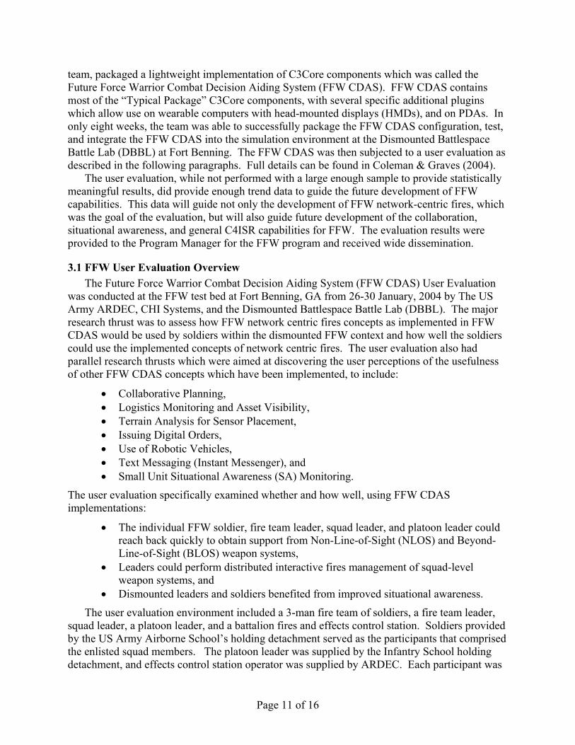
A detailed case study can best illustrate how the C3Core architecture can be used as a framework to assist in development of future systems. The following case study shows the use of C3Core components to provide a surrogate dismounted computing capability for experimentation in Future Force Warrior concepts. In partnership with ARDEC, the C3Core
Page 11 of 16
team, packaged a lightweight implementation of C3Core components which was called the Future Force Warrior Combat Decision Aiding System (FFW CDAS). FFW CDAS contains most of the “Typical Package” C3Core components, with several specific additional plugins which allow use on wearable computers with head-mounted displays (HMDs), and on PDAs. In only eight weeks, the team was able to successfully package the FFW CDAS configuration, test, and integrate the FFW CDAS into the simulation environment at the Dismounted Battlespace Battle Lab (DBBL) at Fort Benning. The FFW CDAS was then subjected to a user evaluation as described in the following paragraphs. Full details can be found in Coleman & Graves (2004).
The user evaluation, while not performed with a large enough sample to provide statistically meaningful results, did provide enough trend data to guide the future development of FFW capabilities. This data will guide not only the development of FFW network-centric fires, which was the goal of the evaluation, but will also guide future development of the collaboration, situational awareness, and general C4ISR capabilities for FFW. The evaluation results were provided to the Program Manager for the FFW program and received wide dissemination.
3.1 FFW User Evaluation Overview The Future Force Warrior Combat Decision Aiding System (FFW CDAS) User Evaluation
was conducted at the FFW test bed at Fort Benning, GA from 26-30 January, 2004 by The US Army ARDEC, CHI Systems, and the Dismounted Battlespace Battle Lab (DBBL). The major research thrust was to assess how FFW network centric fires concepts as implemented in FFW CDAS would be used by soldiers within the dismounted FFW context and how well the soldiers could use the implemented concepts of network centric fires. The user evaluation also had parallel research thrusts which were aimed at discovering the user perceptions of the usefulness of other FFW CDAS concepts which have been implemented, to include:
• Collaborative Planning, • Logistics Monitoring and Asset Visibility, • Terrain Analysis for Sensor Placement, • Issuing Digital Orders, • Use of Robotic Vehicles, • Text Messaging (Instant Messenger), and • Small Unit Situational Awareness (SA) Monitoring.
The user evaluation specifically examined whether and how well, using FFW CDAS implementations:
• The individual FFW soldier, fire team leader, squad leader, and platoon leader could reach back quickly to obtain support from Non-Line-of-Sight (NLOS) and Beyond-Line-of-Sight (BLOS) weapon systems,
• Leaders could perform distributed interactive fires management of squad-level weapon systems, and
• Dismounted leaders and soldiers benefited from improved situational awareness.
The user evaluation environment included a 3-man fire team of soldiers, a fire team leader, squad leader, a platoon leader, and a battalion fires and effects control station. Soldiers provided by the US Army Airborne School’s holding detachment served as the participants that comprised the enlisted squad members. The platoon leader was supplied by the Infantry School holding detachment, and effects control station operator was supplied by ARDEC. Each participant was

Page 12 of 16
provided with the FFW CDAS Combat View system. Additionally, the squad leader and platoon leader were supplied with the Toshiba tablet computer specified by the FFW Lead System Integrator for testing and integration. Finally, all participants were given an opportunity to use the FFW CDAS PDA variant during the “Actions at Danger Area” scenario, with the aim being to assess the utility of the PDA in calling for effects.
The effects control workstation operator used a desktop version of the CDAS netted fires workstation. From the FFW CDAS systems, each soldier and leader could request BLOS and NLOS fires from representative Future Combat System (FCS) weapon systems such as the Mobile Combat System, Future Cannon System, Future Mortar, and Precision Attack Missile (PAM) launchers. The CDAS netted fires workstation managed all incoming calls for fire from soldiers, and assigned weapon systems and munitions in response to the calls for fire. All targeting was provided by users of the FFW CDAS tablet computers, FFW CDAS Combat View, and FFW CDAS PDA. Figures 6, 7, and 8 show the FFW CDAS Combat View, FFW CDAS tablet, and the FFW CDAS PDA.
Figure 6. FFW CDAS Combat View. Figure 7. FFW CDAS Tablet.
Figure 8. FFW CDAS PDA.
The simulation environment consisted of the DBBL’s SimStorm immersive individual combat simulation, and the Mounted Maneuver Battlespace Lab’s (MMBL) OTBSAF version 137. CDAS FFW provided simulation capabilities in the form of a simulated robotic MULE and robotic Platoon UAV. SimStorm allowed the participants to interact with the simulation environment in the first person, with representative squad weapons such as the M4 carbine, M249 SAW, and M203 grenade launcher. The MMBL variant of OTBSAF was used in the user evaluation, as CDAS is able to directly control the firing of FCS weapon systems in this variant.

Page 13 of 16
During the user evaluation, participants were presented with 5 different scenario vignettes which were closely patterned after the FFW scenario developed by the FFW LSI. These 5 vignettes were:
• Sustainment Operations, • Military Decision Making Process, • Maintain Situation Awareness During Movement, • Actions at a Danger Area, and • Actions on Contact.
Each scenario vignette was run one time using the FFW CDAS Combat View and tablet computers. The Actions at a Danger Area vignette was run a second time with the sole object of allowing each soldier to use the PDA, rather than Combat View to perform a call for effects. Following completion of each vignette, all participants completed participant questionnaires.
The major findings and insights derived from the evaluation are summarized below:
Each of the soldiers who participated in the experiment was able to call for fire using the FFW CDAS. All participants felt that sending the call for fire was easy using FFW CDAS. Nearly all participants agreed that sending the call for fire using FFW CDAS was easier than sending a voice call for fire. Most participants felt that effects on target were better using the FFW CDAS call for fire technique than using the current voice call for fire as described in FM 6-30, Observed Fire Procedures. All participants felt that the FFW CDAS PDA was better than the FFW CDAS Combat View or voice call for fire.
The average for single mission times sent from a soldier using the PDA was about 40 seconds from the initial sighting of the target until sending of the call for effects to the CDAS Netted Effects station. This includes the time required to stop moving, extract the PDA from the soldier’s pocket, extract the PDA stylus from the PDA, and prepare and send the call for fire. Actual time required to set up and send the mission with the PDA was much less than overall time, and was on the order of 10 seconds.
The FFW CDAS Combat View users and tablet users were able to select multiple targets for BLOS or NLOS engagement and send calls for effects on the multiple targets simultaneously. This greatly increased the rate at which targets may be engaged as compared with sending consecutive calls for effects on multiple targets.
The ability to collaborate during mission planning was found to be extremely useful by the leaders and soldiers. The platoon leader felt that any time that may have been lost in drawing out a more detailed plan on the tablet (versus drawing out a plan on a paper map), was more than made up for by the instant plan distribution down to the last soldier and the ability to make plan adjustments in real time.
Situational awareness was greatly improved when using the FFW CDAS Combat View. Even the platoon leader and squad leader felt that they had greater awareness using the combat view as opposed to the tablet, although both contain the same data.
The FFW CDAS allowed the leaders to direct soldiers to engage the enemy with the appropriate weapon systems for organic fires distribution, using the M203 as an example. The leaders agreed that a voice interface to perform this function would be invaluable and improve

Page 14 of 16
the utility of the system, over the current mouse-based method. About half the participants agreed that orders sent to them to engage a target were easy understand within the FFW CDAS Combat View.
The concept of instant messaging, if the user must type, is probably not viable, unless the user is in a situation where he is either unable or unwilling to talk on the radio. Voice communications are preferred whenever possible. Leaders invariably used voice, rather than instant messaging.
The better the situational awareness (SA), the more quickly the leader is able to perceive changes to the situation and issue orders to his soldiers. During the battle runs with full SA, the leaders were able to see where their soldiers were and where the enemy was, and able to rapidly issue orders both digitally and verbally. Even the very limited amount of user input required for generation of FFW CDAS digital orders is too much. A means of generating digital orders based on voice interaction with the system would be far more preferable.
More human factors research and investigation is required to determine whether left/right eye dominance, monocular HMD design, and other factors can be overcome to allow the soldier to focus on the combat view display and perform combat functions outside the display. Alternate HMD technologies need to be investigated. Soldiers would not be likely to try to use the display while in close combat and firing a weapon. They would be far more likely to alternate between close combat and display use. During close combat they would rely on their own senses and sighting of the weapons they carry, and during lulls they would refer to the display for any updates to the tactical situation. They also would be very unlikely to interrupt their close combat actions for any but the most dire alert asking them to look at the display, since this switch in attention might very well be lethal during close combat.
The FFW CDAS self-oriented map display was used extensively by all of the participants. This allowed the soldier to navigate the urban complex where the experiment took place, with the map moving and rotating to account for the soldier’s direction of travel and location, and also showing friendly and enemy locations. All participants desired to have this capability in real world applications. The self orientation ability of the Combat View map appears to given the participants a better “connection” to the terrain, and blue/red forces, than if looking at an unoriented map.
Ease of use and rapid training are essential elements for success of any FFW system which is used by the dismounted soldier. Based on the results of this evaluation, the FFW CDAS appears to be moving in the right direction concerning usability and training. Training could be accomplished in less than one hour, and sometimes in less than 10 minutes.
The FFW CDAS evaluation allowed the Army to evaluate both new operational concepts and evolving software/hardware intended to enable those operational concepts. The importance of this is that the use of C3Core allowed this evaluation cycle to unfold both quickly and with minimal cost, while yielding high quality feedback on the operational and system designs involved. Specific conclusions were developed regarding:
• Lethality. Given appropriate equipment, decision aids, and communications architecture, the FFW dismounted soldier’s lethality is greatly increased over that of the present-day soldier.

Page 15 of 16
• Distribution and Management of Squad Level Fires. With good SA, FFW leaders can quickly direct the fires of their organic weapon systems, and can also coordinate direct and NLOS/BLOS fires.
• Reachback. Rapid reachback for NLOS and BLOS munitions is absolutely essential to ensuring the ability of the FFW soldier to fight outnumbered and win. The participants in this experiment were severely outnumbered and could generally destroy the entire hostile force when they had the reachback capability combined with good SA.
• Survivability. The ability to use NLOS and BLOS fires greatly enhances the ability of the FFW soldier to engage and destroy the enemy before the enemy can close within direct fire engagement range. Enhanced situation awareness allows the soldier to see the enemy and shoot first, and at the same time, reduces the likelihood of friendly fire engagements.
• Future Utility. The FFW CDAS user evaluation was an excellent vehicle for probing the netted fires issues and requirements needed to increase the lethality and survivability of the FFW soldier. The insights and findings from this effort laid the groundwork for additional experimentation as the Army moves toward development and fielding of Future Force Warrior netted fires capabilities.
This rapid development and evaluation cycle was able to identify (risk) areas where further R&D was needed and where it wasn't. For the latter, the process helped quantify the expected operational gains in capability. Such rapid cycles are essential to meeting the needs for agile, rapidly evolvable, and customizable C2 structures, processes, and systems identified at the beginning of this paper. Conversely, the traditional system architectures and waterfall design processes would have been unable to support the above type of process.
4. CONCLUSION C3Core has proven to be highly successful at solving the speed, flexibility, and efficiency
problems associated with developing custom C4ISR solutions to solve difficult problems. C3Core application variants and components are being used for both future force C4ISR system development, and also have been fielded into existing systems. Figure 9 summarizes how C3Core has and continues to be successful in providing cost effective, rapidly composable, component-based, custom C4ISR applications and off-the-shelf components to support existing and future C4ISR systems.
The key discriminator (or success factor) between the C3Core architecture and other architectures for C4ISR is the extreme rapidity with which the architecture and its components can be tailored to meet the needs of any given customer. The large repository of components means that we have an off-the-shelf, cost effective solution to meet many of the customer needs. Some repackaging of components may be necessary, but this is quickly done, often without the need to recompile code. Typical packaging to meet a customer need requires about six months if different software interfaces must be accommodated through use of adapter component; or if a new component must be built. Emergency packaging of components for specific needs has occurred in as little as 12 hours. This extreme flexibility and speed in tailoring software, while maintaining low technical and schedule risk for mission critical software, is critical to meeting the emerging development needs of the command and control world.

Page 16 of 16
Figure 9. C3Core Architecture Successfully Supports Multiple C4ISR Application
Development.
5. REFERENCES
CHI Systems, Inc. (2004). CDAS Software Design Description. (Contract No. DAAE30-01-C-1049). Picatinny Arsenal, NJ: US Army ARDEC.
CHI Systems, Inc. (1999). Functional Description Document for Terrain Analysis Injector. Prepared for MARCORSYSCOM.
CHI Systems, Inc. & US Army ARDEC. (2003). Software Requirements Specification for Objective Force Warrior (OFW) Netted Fires Management. (Contract No. DAAE30-01-C-1049). Picatinny Arsenal, NJ: US Army ARDEC.
Coleman, N.R. & Graves, K.P. (2004). Final Report, Future Force Warrior (FFW) Combat Decision Aiding System (CDAS), User Evaluation Test for CDAS FFW Networked Effects Capability. (Contract No. DAAE30-01-C-1049). Picatinny Arsenal, NJ: US Army ARDEC.
Coleman, N.R. & Graves, K.P. (2003). Objective Force Warrior (OFW) Combat Decision Aiding System (CDAS), Implementing Netted Fires for the OFW Squad, Fire Team, and Individual Soldier. Final Report. (Contract No. DAAE30-01-C-1049). Picatinny Arsenal, NJ: US Army ARDEC.
Page 17 of 16
Coleman, N.R., DePaul, J., Graves, K.P., McAllister, G., Pappanagopoulos, G. & Price, J. (2001). Combat Decision Aiding System (CDAS) Research Results from Future Combat Command and Control Concept Evaluation Program (FCC2 CEP) Experiment, 13-24 May 2001. Picatinny Arsenal, NJ: 1999.
Depth & Simultaneous Attack Battle Lab. (1999). Memorandum Report of Future Fires Command and Control (F2C2) Concept Experimentation Program 1 (CEP 1), Designing the Army After Next Field Artillery Battalion Tactical Operations Center (FABNTOC), 99C0639. Fort Sill, OK: 1999.

A-1
Appendix A. Technical Discussion of C3Core Architecture.
A.1 C3Core Architecture-High level description The C3Core architecture can be divided orthogonally into three planes; the service level, the
abstraction level, and the interface or packaging level (Figure A.1).
Figure A.1: Orthogonal planes in the CDAS architecture
The service level defines a hierarchical view of plug-in components and services. Lower level services can be utilized at a higher level and provide building blocks for applications. Services at the lowest levels can be thought of as utilities analogous to operating system level services. Components at higher levels would include plug-ins such as Window_viewport, map_builders, map_renderers, and Network_Bridge in order to provide application-level functionality such as a Common Operational Picture (COP). A COP also would require lower level core backplane services such as database services, drawing services and interface services.
The abstraction dimension utilizes the concepts of Object Oriented Design (OOD) where "Is A" and "Has A" relationships are formed between objects and components. The abstraction facilitates extensibility through two primary means. The first is that components can interact without knowing the final implementation or type of the component. For example, a client may wish to draw a box on the CDAS map display. Provided with a Draw_Box routine, the client does not need to know, or to be concerned with how the line is to be drawn, what platform the operation will happen upon or if this is drawn upon a screen or plotter. This abstraction also facilitates the ability to change the implementation of the operation by different parties to suite their own needs. Abstraction also provides clients a level of "insulation" which allows the system to mutate without affecting 3rd party developers.
The final dimension of the architecture is that of interfaces. Interfaces provide the means in which one component is capable of eliciting actions from another component. In other words, an interface allows one component to communicate with another component. The CDAS architecture clearly delineates between the concept of an invocation interface and the transport mechanism as two distinct elements. This can be seen in Figure A.2.
Figure A.2: C3Core Separates Invocation Interfaces and Transport. An invocation interface is a function, method or procedure call into a component. This
requires that the caller’s invocation is within the callees memory space (i.e., part of the same
Abstraction
Service LevelInterface
Component A Component B Transport

A-2
binary application). The transport mechanism allows components which are in different memory space or computers to communicate. Examples of commonly utilized transport mechanism are COM, CORBA, RPC and TCP/IP. Most of the C3Core plug-in components can be readily "wrapped" to facilitate any transport mechanism. This is demonstrated in Figure A.3.
Figure A.3: C3Core Plug-in Wrapping for Transport.
There are instances where a 3rd party component needs to reside within the same memory space as another C3Core component. This may be required when invocations need to be as fast as possible or when data needs to be shared between components. The C3Core architecture provides for this through the use of "Plugins". A Plugin is a software component which is dynamically loaded at run time by the application and allows the component to "connect" to the application memory space. Often plugins are used as a proxy agent, which can allow external applications to communicate with C3Core. An example of this is shown in Figure A.4.
Figure A.4: C3Core Plug-in Transport to Third Party Plug-In A.2 Component View
The C3Core software architecture is component-based. Though the meaning of “component”
varies from author to author, within this C3Core, a component is defined as a consistent set of software or software packages which is well encapsulated and provides a service or collection of services as a logical unit. Typically, components build upon the services provided by components at lower levels in order to provide higher level functionality. Through the organization of components in this fashion, a component hierarchy is often formed.
Components at the lowest conceptual level within C3Core provide core backplane services and form the leaves of the hierarchical tree. These components tend to be generic services such as Input/Output, Logging and Alerting, and for convenience are all contained in the core component for the architecture. These core level services can also be highly specialized such as a protocol translator. As one moves up the component hierarchy, components become more specialized and domain specific. For example, the fire_docked and fire_tab plug ins, which we will call the Fires component, are high level components specific to military fires and effects management. The bulk of all components within C3Core tend to fall in the middle of the
Component A Component B
Transport Transport
CDAS application
Plugin Manager
Proxy 3rd Party application Transport
CDAS application space
N

A-3
hierarchy and provide services such as Database, Collaboration and Knowledge Bases. A conceptual description of the Fires component is presented in the following example.
In the fires example, two different user interfaces could be connected to the C3Core architecture. This is possible, since each plug in or component contains an abstract interface layer. Since the two different user interfaces are separate components, different user interface looks and feels can be tailored to specific domains. For example, the effects control personnel at an FCS company and an FCS Unit of Action would have significantly different user interfaces, though both need most of the common services from the Fire_tab and fires_docked plugins. The use of an abstract interface with all plugins facilitates the ability to readily "plug and play" different visual components. The abstract interface communicates with the two fires user interface plugins and defines the control behavior of the interface. This may include such items as user input validation and presentation data format. The use of an abstract user interface insulates the application from specific windowing systems such as MFC and X11.
In this example, the user interfaces communicate to the abstract interface, which then communicates with the Fires component to invoke operations and provide user input data. A 3rd party component developer may also invoke this abstract interface to invoke behavior, such as is the case when integrating with existing legacy systems. This also facilitates the use of alternative input devices such as eye, voice or terminal data entry.
Figure A.5: Typical Component Interfaces in Configuring CDAS Components.
As shown in Figure A.5, the Fires component relies on services from the Logistics and C2 components to provide the functionality to perform fire control. Each of these components consists of a number of plugins such as rollup_tab, icon_rep, logistics_tab, and unit_rep. To continue, Situation Awareness requires a feed of the tactical picture which is received from the Communications component. The Communications component insulates the C2 component from the underlying physical communications medium and protocols. In this example the Radio and Network components both receive tactical information. These components would be composed in turn of smaller, service type plug-ins such as network_bridge and email.
Fires
Abstract Interface
User Interface 1 User Interface 2
Logistics
C2
Communication Radio
Network