teletrac navman eld installation guide - btcgps.com · eld installation parts outline 2 the...
TRANSCRIPT

Teletrac Navman ELD Installation Guide
05/23/2017
V.1
1

ELD Installation Parts Outline
2
The Teletrac Navman ELD Certified solution is built on the Qube300, MNAV, JPOD/VPO hardware platform. Established installation process for these units must be applied. The information in this guide will provided a hardware overview and ELD specific information. For questions, please contact Teletrac Navman Field Service team at [email protected]
Parts required for ELD installation• Qube300 – antenna, power harness• MNav950 – cradle, and MN950 cable• JPOD2 or VPOD – Always required for ELD compliance• Product Documentation – Left in each vehicle

Qube 300 Overview
3
Qube300
1) Serial Port 1: RJ45 Connector Type – MNav and Driver ID 2) Power Connection: Constant Switched and Ground3) Serial Port 2: 8 PIN Harness – SAT Modem, Temp 1-Wire, Serial Data Capture, ConEx4) Serial Port 3: ConEx, JPOD, VPOD 5) SIM Card6) GPS Antenna7) Cellular Antenna

Power connections
4
The power connections will be made to a location that is appropriate to the vehicle being installed, this may be the key switch, terminal block at fuse box, or other location deemed appropriate. A digital multi-meter should always be used to confirm connections.
The Qube300 needs 3 connections for power: • Red – Constant – has power at all times regardless of key position• Pink – Ignition – must be connected to a true ignition source that provides power when the key
is in the On position and while vehicle is cranking• Black – ground – you will use the provided ring terminal, screw, and star washer to make this
connection to a good metal location under the dash
*Scotch locs and T-Taps are never recommended*
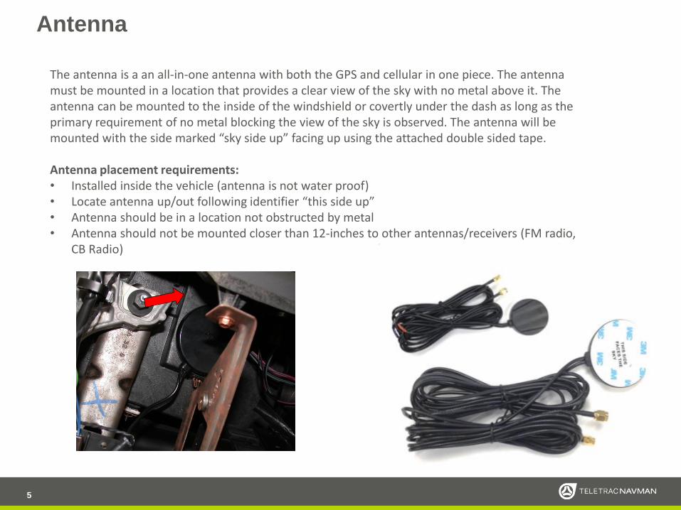
Antenna
5
The antenna is a an all-in-one antenna with both the GPS and cellular in one piece. The antenna must be mounted in a location that provides a clear view of the sky with no metal above it. The antenna can be mounted to the inside of the windshield or covertly under the dash as long as the primary requirement of no metal blocking the view of the sky is observed. The antenna will be mounted with the side marked “sky side up” facing up using the attached double sided tape.
Antenna placement requirements:• Installed inside the vehicle (antenna is not water proof)• Locate antenna up/out following identifier “this side up”• Antenna should be in a location not obstructed by metal • Antenna should not be mounted closer than 12-inches to other antennas/receivers (FM radio,
CB Radio)

MNAV 950
6
MNav 950 will be installed in a location that allows the driver easy access to use the display, but one that will not interfere with any functions of the vehicle or the drivers visibility of the road and mirrors.
When the location is determined the MNav 950 must be mounted using the correct screws or nuts & bolts (not provided). Run the MNav 950 cable to Qube300, care must be taken that the cable is routed in a manner that will not cause damage to the cable.
Note: Always review the MNAV Installation location with the customer prior to mounting the device.

JPOD – VPOD Vehicle Diagnostics Interface Cables
One of the following vehicle diagnostics interface cables must be used. This is an ELD requirement and failure to
properly install these interfaces will negate compliance.
7
VPOD2 for OBDII vehicles

Vehicle Diagnostics Interface
8
Vehicle diagnostics will be interfaced using one of the available cables. The cable will be installed to the factory diagnostics connector. The Mack and Volvo specific cables will be installed using the proper method for those cables.
1. Locate the diagnostic connector (usually found under the driver side of the dash) and determine whether it is a 6 or 9 pin. 2. Run the JPOD2 from the dash to the Qube 300. 3. Disconnect the factory diagnostic connector from the dash. 4. Replace the factory male connector with JPOD2 6 or 9 pin male deutch connector dongle. 5. Connect the factory male connector to the Vehicle’s Management female connector. 6. Connect the Vehicle Management Cable to the Main Cable’s red connector. Tighten the barrel connector and wrap the connection in electrical tape. 7. Secure the JPOD2 with zip ties
Ring adaptor for Kenworth and
Peterbilt

ELD User Manuals
Included in each hardware shipment the installation technician will find a user manuals and an ELD sticker. These documents must be left in the vehicle. Please leave this information with the customer contact or on the Driver's seat after the installation is completed.
Leave behind documents: • ELD On Board Sticker• ELD Quick Start Guide• Garmin User Manual
9

PRESENTATION NOTE, IF NECESSARY10
Installation Verification – Live Test (RIMU)
Power the system up and follow the standard RIMU installation verification process to test Qube and Messaging functionality.
An installer login is available as: 6789
After completing RIMU verification the installer should also check the ELD Indicator ( when functioning properly the Icon should be green ) by selecting the Icon and looking at the line items checking for any warnings, malfunction messages for the following : o Data recording compliance o Data transfer compliance o Engine synchronization compliance o Positioning compliance o Power complianceo Timing compliance o Data transfer data o Engine synchronization data o Missing required data elements data o Power data o Unidentified records data
Upon inspection of the Diagnostics screen each line item should read “ OK “ in green text under the < State > column as shown below when functioning properly. If warning should read “ warning “ in yellow text ; If malfunction should read “ malfunction “ in red text.
Any failures must be called into the Verification department for live troubleshooting.

Verification Support
11
ELD product will be verified by calling Teletrac Navman verification number to confirm complete functionality of the installed hardware.
Teletrac Navman verification number –877.778.2478
Before calling in for verification please be sure you have completed at least 2 ignition cycles of the installed Qube300 so the unit has pinged the Teletrac Navman servers and will speed up the verification process.