teletrac navman tm470 eld installation guide...eld installation parts outline 3 the teletrac navman...
TRANSCRIPT
Teletrac Navman TM470 ELD Installation
Guide

Contents
2
Topic Page(s)
ELD Introduction 3
TM470 Overview 4 - 6
TM470 Installation 7
Power Connections 6 - 7
Antenna Installation 11
Garmin670 Installation 12 - 13
Diagnostic Connections 14 – 18
JBUS Port Replacement – 2007+ Peterbilt / Kenworth 19
ELD Documentation – In-vehicle 20-21
Testing (RIMU) 17 - 22
Verification and Technical Support 23 - 27
DE / RE Installation (Garmin reset) 28
Remove ELD Application (Garmin) 29
Troubleshooting 30 - 32
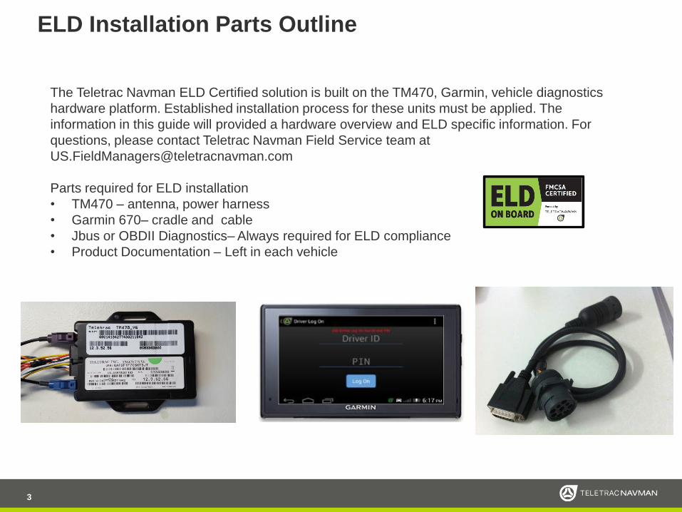
ELD Installation Parts Outline
3
The Teletrac Navman ELD Certified solution is built on the TM470, Garmin, vehicle diagnostics
hardware platform. Established installation process for these units must be applied. The
information in this guide will provided a hardware overview and ELD specific information. For
questions, please contact Teletrac Navman Field Service team at
Parts required for ELD installation
• TM470 – antenna, power harness
• Garmin 670– cradle and cable
• Jbus or OBDII Diagnostics– Always required for ELD compliance
• Product Documentation – Left in each vehicle
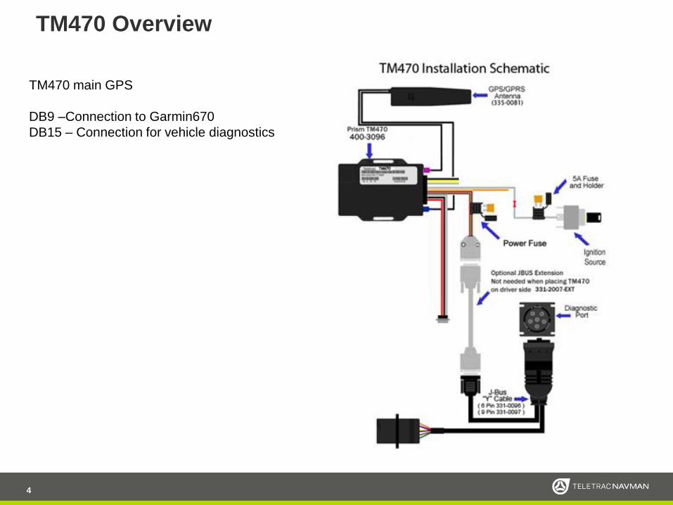
TM470 Overview
4
TM470 main GPS
DB9 –Connection to Garmin670
DB15 – Connection for vehicle diagnostics

Unit Picture Overview
10
A GPS/GPRS Dual AntennaB (5 amp) Fuse/holder
C TM470 D VLU Power Harness
E Red Wire- Power Voltage input “+”F White Wire - Ignition Voltage input "+“
G Ground Wire Voltage input “-”H Blue Wire - Output 1 "-"
Grey Wire - Input 1 "-"Orange Wire - Input 3 "+"
Twisted Yellow, Black and White- FIL L Display connection (DB9) Q OBDII ext. cable, O B&B Box Y OBDII y Cable
S 3 Pin Power HarnessP Vehicles Data Connection DB15 connection Connect Jbus Y Cable or OBDII Cable
W Jbus 9 pin
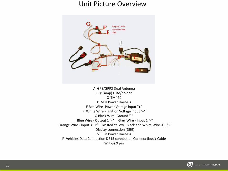
Unit Picture Overview
10
A GPS/GPRS Dual AntennaB (5 amp) Fuse/holder
C TM470 D VLU Power Harness
E Red Wire- Power Voltage input “+”F White Wire - Ignition Voltage input "+“
G Black Wire- Ground “-”Blue Wire - Output 1 "-" I Grey Wire - Input 1 "-"
Orange Wire - Input 3 "+“ Twisted Yellow , Black and White Wire -FIL "-"Display connection (DB9) S 3 Pin Power Harness
P Vehicles Data Connection DB15 connection Connect Jbus Y Cable W Jbus 9 pin

• The TM470 should be installed in
a covert location • TM470 hardware is not water proof and
must be installed inside the vehicle
• Avoid locations that as subject to
excessive heat
• Choose a location that will not interfere
with normal operation of the vehicle
• Avoid locations that are accessed for
normal vehicle maintenance
• Mount the device with screws or wire
ties
• Spare antenna cable and power
harness should be neatly bundled
and secured
7
TM470 Installation Location

Power connections - Explained
8
The system is designed to receive power and ground via the JBUS connector. Only the Ignition wire is to be
connected to a source of power. Attach one end of fuse holder to the Ignition run source that will rest at ground while
ignition is off (verify with suitable Multi-meter).
Recommended locations are behind the ignition cylinder or behind fuse box. To test for ignition, use a multi-meter to
find a wire that has +12volts while the engine is being cranked and turns off when the key is turned off.
The power and diagnostics connections for the 2013+ Mack and 2013+ Volvo are special circumstances. Please
reference those sections of this installation guide for the correct method on those vehicles.
Typical Ignition Key Cylinder
Note1: If the vehicle has a master battery disconnect switch, TM470 must be connected
on the battery (hot) side of that switch.
START
OFF
ACC
ON

Power Connections JBus vehicles continued
Some vehicles the JBus connector does not supply the required constant and ground needed for the TM470. In these cases the installer will be
required to make an alternate power connections.
• All connections must either be soldered (preferred) or poke and wrapped. Scotch-Loc, or T-Tap connections may not be used, if they are
discovered during a QC inspection they will be corrected and installer will be billed for repairs.
• Use of supplied provided fuse holders is mandatory, their placement should be as close to the connection point in the vehicle as possible. These
fuses are provided to protect the vehicle not the TM470.
Identifying correct wires• Remove any interior trim as necessary to gain access to the vehicles wiring as well as any areas where interconnecting wire harnesses
may be located.Attach fuse holders to the Constant and Ignition wires of the TM470 power harness.It is always recommended the installer locate the constant and ignition wires at the ignition switch. (This is not a given acceptablelocation for connection. There may be extreme difficulties accessing the ignition switch wires, the wires may be low amperage controlwires not acceptable to power the TM470. In these cases the installers experience and knowledge will allow connections in otherappropriate locations.)Always use a multimeter in identifying the appropriate wires following the guidelines on the next page.
••
•
25

te
Power Connections JBus vehicles Alternate Power Input
It is always a good practice to verify that you are getting a good constant and ground connection through the JBus connector. There are numerous
situations where there will not be power or ground provided from the connector. In these situations an alternate power input is required to be
sourced. You will use a 3-pin power connector to make the power connections. This is the same 3-pin connector used for OBDII installations,
connection method will be identical to the OBDII installation.
Standard connection using the JBus VD connection to power theVLU.
Connection using provided 3-pin harness needed when alternapower connection is required.
26

Antenna
11
The antenna is a an all-in-one antenna with both the GPS and cellular in one piece. The antenna must be mounted in a location that provides a clear view of the sky with no metal above it. The antenna can be mounted to the inside of the windshield or covertly under the dash as long as the primary requirement of no metal blocking the view of the sky is observed. The antenna will be mounted with the side marked “sky side up” facing up using the attached double sided tape.
Antenna placement requirements:• Installed inside the vehicle (antenna is not water proof)• Locate antenna up/out following identifier “sky side”• Antenna should be in a location not obstructed by metal • Antenna should not be mounted closer than 12-inches to other antennas/receivers (FM radio,
CB Radio)

Garmin670
12
Garmin670 will be installed in a location that allows the driver easy access to use the
display, but one that will not interfere with any functions of the vehicle or the drivers visibility
of the road and mirrors.
When the location is determined the Garmin670 must be mounted using the correct screws
or nuts & bolts (not provided). Run the Garmin670 cable to TM470, care must be taken that
the cable is routed in a manner that will not cause damage to the cable.
Note: Always review the Garmin Installation location with the customer prior to
mounting the device.

Assembling the Garmin Ram Mount
1.
2.
3.
Connect the Garmin power cable to the DB9 of the TM470.
Take the magnetic holder and snap it onto the top of stand mounting ball.
Plug the Garmin power cable into the side of the magnetic holder. Do not attempt to
plug the power cable directly into the Garmin display as they are not compatible.
The display will now attach to the mount magnetically. You will note the display will only
attach in one orientation because of the magnetic mount.
4.
24

Vehicle Diagnostics Interface Cables
One of the following vehicle diagnostics interface cables must be used. This is an ELD requirement and
failure to properly install these interfaces will negate compliance.
**Note** The OBD or JBUS Port must have good power and ground on the correct PINs for the diagnostic
function to work. These power sources can be lost due to blown fuses. Always verify at time of installation.
14
Y-Cable and diagnostics adapter for OBDII vehicles
9-pin y-cable 6-pin cable y-cable

Vehicle Diagnostics Interface - JBUS
15
Vehicle diagnostics will be interfaced using one of the available cables. The cable will be installed
to the factory diagnostics connector.
1. Locate the diagnostic connector (usually found on the driver side of the dash) and determine
whether it is a 6 or 9 pin.
2. Run the y-cable from the dash to the TM470.
3. Disconnect the factory diagnostic connector from the dash.
4. Replace the factory male connector with JBus 6 or 9 pin male deutsch connector dongle.
5. Connect the factory male connector to the Vehicle’s Management female connector.
6. Connect the Vehicle Management Cable to the Main Cable’s red connector. Tighten the barrel
connector and wrap the connection in electrical tape.
7. Secure the y-cable with zip ties

Vehicle Diagnostics Interface - OBDII
Correct connection for constant, ignition and ground for OBDII• The installer is required to change the connection method when installing the TM470V8 into an OBDII vehicle. It is important that this is
followed correctly or the customer will experience issues with the installation, specifically battery life of the vehicle.
The installer must disconnect the 3-pin power harness from its connection point as shipped, the included 3-pin harness will be plugged
into its place and all power connections will be completed as normal at the ignition switch or other approved location. See Page 10 for unit overview•
18
• Remove the factory OBDII connection and connect the OBDII Y-adaptor to the factory connection.
• Replace the factory OBDII connection with the OBDII Y-cable.
• Next place the other end of the OBDII adaptor into the vehicle connection of the B&B box and plug the host extension cable into the host connection of the B&B box.
• The other end of the extension cable plugs
into DB15 of the TM470 Harness.

Vehicle Diagnostics Interface –Mack 2013+
Power and diagnostics connections for the 2013+ Mack is made using the special harness. After you have connected the harness into the Macktruck you will connect to the TM470 VLU using the DB15 connection. You will be required to connect the white ignition wire separately as itdoes not run through the DB15 connector.
The connection strip in the Mack truck is labeled for easy connectionby the installer.The connection are as follows –
••
•
•
•
Red – Constant battery powerWhite – IgnitionGrey – Serial A – for VDBlue – Serial B – for VDBlack - Ground
27

Vehicle Diagnostics Interface – Volvo 2013+
Power and diagnostics connections for the 2013+ Volvo is made using the special harness. After you have connected the harness into the Volvotruck you will connect to the TM470 VLU using the DB15 connection. You will be required to connect the white ignition wire separately as itdoes not run through the DB15 connector.
Plug the Power and Ground connection into B2 on the Fuse Box,Plug Ignition into B4.If you have no power for the ignition plug make sure there is a fusein F31/F32 fuse.
28 PRESENTATION NOTE, IF NECESSARY

Kenworth – Peterbilt: Diagnostic Port Installation
Ring adaptor for 2007+ Kenworth and Peterbilt
Trucks
Kenworth and Peterbilt trucks (2007+) utilize a
unique mounting system for the 9 PIN diagnostic
connection. To support the OEM port replacement
TTNM have designed a ring adaptor that will
secure port in place on the dashboard.
1. Remove the OEM port by unscrewing the
mounting nut.
2. From the inside of the dashboard, fit the
replacement port into the OEM location.
3. From the front of the dashboard, fit the ring
adaptor legs through the hole.
4. Inside the dashboard, pinch the ring adaptor
legs to secure the replacement port in place.
• Note: Screw the OEM mounting nut onto the
factory port so it is available to restore the
vehicle to OEM spec at time of DE-Installation

ELD Documents - In vehicle
• Each installation kits has a ELD DRIVE
user manual (66 pages)
• User manual and ELD sticker must be
placed in the vehicle
• IMPORTANT: Per FMCSA 49 PARTS
385, 386, 390, and 395, this guide must
be kept in the vehicle at all times
20

21
Installation Verification – Live Test (RIMU)
Power the system up and follow the standard RIMU
installation verification process to test TM470 and
Messaging functionality.
After completing RIMU verification the installer should also check the
ELD Indicator ( when functioning properly the Icon should be green )
by selecting the Icon and looking at the line items checking for any
warnings, malfunction messages for the following :
o Data recording compliance
o Data transfer compliance
o Engine synchronization compliance
o Positioning compliance
o Power compliance
o Timing compliance
o Data transfer data
o Engine synchronization data
o Missing required data elements data
o Power data
o Unidentified records data
Upon inspection of the Diagnostics screen each line item should read “
OK “ in green text under the < State > column as shown below when
functioning properly. If warning should read “ warning “ in yellow text ;
If malfunction should read “ malfunction “ in red text.
Any failures must be called into the Verification department for
live troubleshooting.

RIMU URL - https://onlineavl2sup-
us.navmanwireless.com/AVL3WebSysadmin/Account/Login
Enter Username and Password and select the “Log In”
button
If you have DIRECTOR access this will be the same login
credentials.
Username will be your email address. Please enter your
password.
ELD Verification
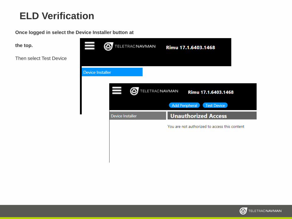
Once logged in select the Device Installer button at
the top.
Then select Test Device
ELD Verification

Now select Any Device
ELD Verification
You will then enter the min number of the device twice, once in the Qube box and the other for the M-Nav box. The min number will be the 0Cxxxxxxx to the right of the IP
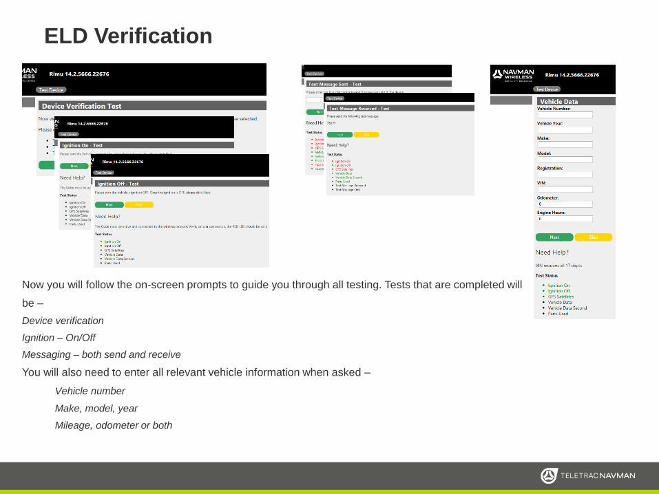
Now you will follow the on-screen prompts to guide you through all testing. Tests that are completed will
be –
Device verification
Ignition – On/Off
Messaging – both send and receive
You will also need to enter all relevant vehicle information when asked –
Vehicle number
Make, model, year
Mileage, odometer or both
ELD Verification

After all tests have been completed you will be
shown a list that details in green or red which tests
were completed/passed (Green) and which failed
(Red).
Any failed tests can be retested by selecting the
Red text to go back and redo that portion.
Once all tests are completed you will be given a
self-test code that you need to document.
Progress and Test Results

Installation worksheet and Verification
Prior to calling Teletrac Navman make sure you have the following fields filled out.
Work Order Number Case Number Date
Customer Name
Installed By (tech name) Installation Company
Vehicle Number VIN Number Odometer
Year Make & Model License Plate
Options Installed (JBUS, OBDII, PTO, Display, etc.)
Numbers to call
Activation and Testing (714) 934 8770 or expanded support (847)832-6987
Pass Code (Given by Teletrac Navman Verification after testing)
37

Installation Verification support
Technical Support Department
Hours: Monday – Saturday9am – 6:00pm (CentralTime)
e-mail: [email protected]
Toll Free Phone # (714) 934-8770 Installation Support Phone #
847.832.6987
Before calling in for verification please be
sure you have completed at least 2 ignition
cycles of the installed TM470 so the unit
has pinged the Teletrac Navman servers
and will speed up the verification process.

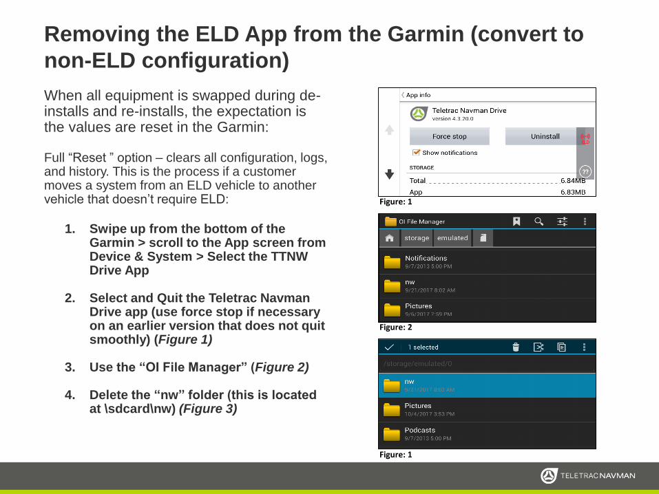
When all equipment is swapped during de-
installs and re-installs, the expectation is the
values are reset in the Garmin:
Delete only old ELD data, but leave the Garmin
configured for ELD use in a different vehicle. This is the
standard DE/RE installation process:
1. Swipe up from the bottom of the Garmin >
scroll to the App screen from Device &
System > Select the TTNW Drive App
2. Select and Quit the Teletrac Navman Drive
app (use force stop if necessary on an
earlier version that does not quit smoothly)
(Figure 1)
3. Use the “OI File Manager” (Figure 2)
4. Delete the “nw\data\eld.db” folder (this is
located at \sdcard\nw) (Figure 3)
DE/RE Installation Special Instructions
Figure: 1
Figure: 2
Figure: 1
When all equipment is swapped during de-installs and re-installs, the expectation is the values are reset in the Garmin:
Full “Reset ” option – clears all configuration, logs, and history. This is the process if a customer moves a system from an ELD vehicle to another vehicle that doesn’t require ELD:
1. Swipe up from the bottom of the Garmin > scroll to the App screen from Device & System > Select the TTNW Drive App
2. Select and Quit the Teletrac NavmanDrive app (use force stop if necessary on an earlier version that does not quit smoothly) (Figure 1)
3. Use the “OI File Manager” (Figure 2)
4. Delete the “nw” folder (this is located at \sdcard\nw) (Figure 3)
Removing the ELD App from the Garmin (convert to
non-ELD configuration)
Figure: 1
Figure: 2
Figure: 1

TROUBLESHOOTING
31
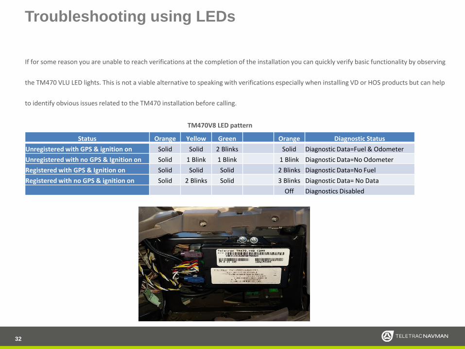
Troubleshooting using LEDs
If for some reason you are unable to reach verifications at the completion of the installation you can quickly verify basic functionality by observing
the TM470 VLU LED lights. This is not a viable alternative to speaking with verifications especially when installing VD or HOS products but can help
to identify obvious issues related to the TM470 installation before calling.
32
Status Orange Yellow Green Orange Diagnostic Status
Unregistered with GPS & ignition on Solid Solid 2 Blinks Solid Diagnostic Data=Fuel & Odometer
Unregistered with no GPS & Ignition on Solid 1 Blink 1 Blink 1 Blink Diagnostic Data=No Odometer
Registered with GPS & Ignition on Solid Solid Solid 2 Blinks Diagnostic Data=No Fuel
Registered with no GPS & ignition on Solid 2 Blinks Solid 3 Blinks Diagnostic Data= No Data
Off Diagnostics Disabled
TM470V8 LED pattern

VLU Troubleshooting
33
No Power or Ignition to the Unit - Check the TM470 Power & Ignition fuses. Replace if needed. (Always replace fuses with the same amperage fuse.)
a. Check the Power connection point and confirm that connection is solid. Fix the connection as needed.
*** If unit is a TM470V8 power and ground will come from JBusconnection. ***
b. Check the Ground connection point and confirm that the connection is solid and free from rust or corrosion. Fix the connection as needed.
*** If unit is a TM470V8 power and ground will come from JBus connection. ***
c. Check the vehicle fuse for that power source. Replace as necessary.
*** Vehicles with JBus the factory vehicle fuse will sometimes blow causing unit not to receive power. **
d. Fix any cut or broken wires and connections. *** Most installs will have 1(JBus) to 3 (Tracking only) connections wires. Power, Ignition & Ground***
No GPS
a. Remove antenna connectors and make both connectors don’t have any bent pins on the inside of the connectors.
a. Make sure antenna hasn’t fallen down and the antenna has the correct side facing the windshield of the vehicle.
a. The correct side should say sky side. Make sure antenna isn’t blocked by metal and is only covered by plastic if antenna is hidden under dash.
Display is Not Working: No power to Tablet no red light, Tablet stuck on loading stage
a. Remove the Tablet and check for broken or stuck cradle Pinsb. Check and make sure that DB9 is connected to TM450/470 power harnessc. Check for bend or brakes in the CTO cable.d. Try swapping out CTO cradlee. Try swapping out CTO
Android will not pair or doesn’t see Bluetooth: Disconnect power to the
unit then unplug Bluetooth. Reconnect Bluetooth then reconnect power to the unit: make sure Bluetooth is secured and not hanging down loose. Try swapping out Bluetooth or Android if the steps above do not work.
Android restart/reboot when it has a route. Request a replacement from
your account rep. Tablet probably needs firmware updated
Android app keeps crashing. Request a replacement from your account rep.
Tablet probably needs firmware updated
No Diagnostics
a. Check and make sure JBus or OBDII cable is connected.b. Check and make sure OBDII y cable is plugged directly to the Factory OBDII
cable and not through a 3rd cablec. Check for blown fuse on vehicle. ** should be a 10amp fuse on fuse box for
Ford & Freightliners , 20amp fuse marked LTR for Chevy vehicles **
Unit will not register:a. Unplug Power harness wait 10 seconds then reconnect unit.
b. Check and make sure the purple antenna is securely connected to the unit and
pins are not bent.
c. Disconnect power then remove SD card: to make sure sim card holder isn’t
broken, try cleaning the SD card and put back into unit. Reconnect power to
unit.

Disclaimer
34
Although Navman Wireless’s goods, services, and software can be useful as a part of a logistics and/or property management
program, Navman Wireless makes no warranty whatsoever that its goods, services, or software will prevent or
mitigate any theft, misappropriation, injury, delay, or other adverse condition. Navman Wireless’s goods, services,
and software are not designed, intended, authorized, or warranted to be suitable for use or resale as control
equipment in, or for other applications related to, hazardous or critical environments requiring fail-safe performance, such
as in the operation of nuclear facilities, aircraft navigation or communications systems, air traffic control, life support,
weapons systems, or other application in which the failure of a product could lead to death, personal injury, or physical or
environmental damage.