technical specification for construction works · clarence city council – technical specification...
TRANSCRIPT

Clarence City Council – Technical Specification for Construction Works - June 2008 1
1
TECHNICAL SPECIFICATION FOR CONSTRUCTION WORKS
I N D E X
PART TITLE 1 GENERAL 2 EARTHWORKS 3 SUBSOIL DRAINS 4 STORMWATER AND SEWER RETICULATION 5 WATER RETICULATION 6 MATERIAL AND PAVEMENT CONSTRUCTION 7 CONCRETE KERB AND CHANNEL 8 FOOTPATH CONCRETE 9 CONSTRUCTION OF MINOR CONCRETE STRUCTURES 10 SEALING 11 ASPHALT SURFACING 12 SERVICE CONDUITS 13 GUIDE POSTS AND STEEL BEAM GUARD FENCE

Clarence City Council – Technical Specification for Construction Works - June 2008 2
2
TECHNICAL SPECIFICATION FOR CONSTRUCTION WORKS
PART 1
GENERAL
I N D E X
CLAUSE TITLE 1.1 GENERAL CONDITIONS OF CONTRACT 1.2 INTERPRETATION OF DOCUMENTS 1.3 STANDARDS 1.3.1 AUSTRALIAN STANDARDS 1.3.2 STANDARD DRAWINGS 1.4 ENDORSED DRAWINGS 1.5 ENGINEER 1.6 NOTICE OF COMMENCEMENT OR RESUMPTION OF
WORK 1.7 HOURS OF WORK 1.8 CONSTRUCTION PROGRAM 1.9 SITE OFFICE 1.10 EXISTING SERVICES 1.11 EXISTING ROADS 1.12 ACCESS 1.13 TRAFFIC CONTROL 1.13.1 SIGNS AND LIGHTS 1.13.2 STOP AND SLOW SIGNS 1.13.3 INSPECTION 1.14 INSPECTIONS 1.15 EXPLOSIVES 1.16 LOT PEGS 1.17 SURVEY MARKS 1.18 MAINTENANCE

Clarence City Council – Technical Specification for Construction Works - June 2008 3
3
1.1 GENERAL CONDITIONS OF CONTRACT All works are to be carried out in accordance with the Australian Standards, General Conditions of Contract AS2124-1992, this Specification, the Drawings and are all to be carried out to the satisfaction of the Engineer. 1.2 INTERPRETATION OF DOCUMENTS If there is any inconsistency between the wording of the clauses in this Specification and the General Conditions of Contract, the clauses in this Specification are to take precedence over clauses in the General Conditions of Contract. Notes and details on the Drawings are to take precedence over this Specification. 1.3 STANDARDS 1.3.1 Australian Standards Wherever reference to an Australian Standard is stated it is to include a reference to the latest issue of the particular Australian Standard applicable at the commencement date of the contract. 1.3.2 Standard Drawings The standard drawings referred to in the specification shall be those as issued by the Council. 1.4 ENDORSED DRAWINGS The Drawings referred to in this Specification are those endorsed by the Council's Engineer. The Drawings must not be varied without the written approval of the Engineer. 1.5 ENGINEER In this Specification the term "Engineer" is the Engineer, or the Engineer's representative, employed by the Clarence City Council. The Engineer will inspect the work to ensure compliance with the Contract. The Engineer may appoint a representative to act as Clerk of Works and the Engineer or his representative has the right to inspect all stages of the work. 1.6 NOTICE OF COMMENCEMENT OR RESUMPTION OF WORK The Engineer is to be notified in writing on the approved form at least two (2) working days before the commencement, or resumption of work, where the work has ceased for six (6) or more working days.

Clarence City Council – Technical Specification for Construction Works - June 2008 4
4
1.7 HOURS OF WORK Subject to paragraph 1.13, no works to be carried out pursuant to this contract is to proceed outside the hours of 7.00 a.m. to 5.30 p.m. Monday to Friday or on public holidays without the prior approval of the Engineer and such other approvals as may be required. The Contractor must pay the costs of any additional inspections made necessary by work outside the times specified above. 1.8 CONSTRUCTION PROGRAM Prior to commencement of work on site the Contractor is to provide the Engineer with two (2) copies of the proposed construction program. This is to be in an acceptable bar chart form showing planned weekly progress and is to have provision for entering comparative actual progress. The Engineer must be notified in writing of any changes to the programme. 1.9 SITE OFFICE The Contractor is to provide on site an office that may be used by the Engineer, containing a complete set of the Drawings at all times. 1.10 EXISTING SERVICES The Contractor must not interfere with the Council's Services without prior approval of the Engineer. All damage caused to existing Council services by the Contractor will be repaired by the Council at the Contractors expense unless otherwise approved by the Engineer. 1.11 EXISTING ROADS Any damage to a local highway, caused by the Contractor, is to be repaired in accordance with the Engineers requirements at the Contractor’s cost. No material is to be stored on any local highway without approval of the Engineer. 1.12 ACCESS Access over abutting properties is not permitted unless agreed to in writing by the owners and occupiers. Access to existing properties is to be maintained at all times.

Clarence City Council – Technical Specification for Construction Works - June 2008 5
5
1.13 TRAFFIC CONTROL Without limiting the provisions of Clause 15, of the General Conditions of Contract, the Contractor is to; 1.13.1 Sign and Lights Provide signs and lights, complying with the Manual of Uniform Traffic Control Devices AS 1742 and the Tasmanian Traffic Regulations. 1.13.2 Stop and Slow Signs Provide traffic control signage including "stop"/"slow" signs when less than two lanes are available to traffic. 1.13.3 Inspection Provide regular inspection and maintenance of signs, lights, safety equipment and barriers at all times including inspections on weekends and holidays. 1.14 INSPECTIONS The Contractor must give the Engineer notice of all inspections in accordance with this Specification. The Engineer may require the Contractor to uncover any works that have not been inspected by the Engineer, and require remedial works to be carried out at the Contractor's expense. 1.15 EXPLOSIVES No blasting is to take place on site without all necessary approvals being given by the appropriate authorities. 1.16 LOT PEGS Lot Pegs must not be disturbed by the Contractor unless it is necessary to carry out the work of the Contract. If lot pegs are disturbed by the Contractor the lot pegs are to be replaced by a licensed surveyor as soon as possible. The Contractor is responsible for the replacement of lot pegs prior to the works being placed on maintenance.

Clarence City Council – Technical Specification for Construction Works - June 2008 6
6
1.17 SURVEY MARKS State Permanent Marks must not be disturbed without the written permission of the Engineer. The Engineer will require the Contractor to pay the cost of re-establishing the State Permanent Marks if disturbed. Temporary benchmarks must be established on site in accordance with the Drawings and must be maintained by the Contractor for the duration of the contract. 1.18 MAINTENANCE Upon completion of the work, the Engineer will arrange an inspection to certify that the works are completed. Subject to the approval of the Engineer the works are to be maintained for a period of six (6) months or as otherwise required by the Engineer. At the end of the Maintenance period the Engineer will arrange a final inspection. Subject to the approval of the Engineer the works may be taken over by Council.

Clarence City Council – Technical Specification for Construction Works - June 2008 7
7
TECHNICAL SPECIFICATION FOR CONSTRUCTION WORKS
PART 2
EARTHWORKS
I N D E X
CLAUSE TITLE 2.1 SCOPE OF WORK 2.2 STANDARDS 2.3 MATERIALS 2.3.1 FILLING MATERIAL 2.3.2 GEOTEXTILE FABRIC 2.4 SET-OUT 2.5 DRAINAGE 2.6 CLEARING AND GRUBBING 2.7 STRIPING AND STOCKPILING OF TOPSOIL 2.8 EXCAVATION 2.8.1 EXTENT OF WORK 2.8.2 DISPOSAL OF SURPLUS MATERIAL 2.9 FILLING 2.9.1 UNSOUND FOUNDATIONS 2.9.2 BENCHING 2.9.3 PLACING AND COMPACTION 2.10 GEOTEXTILE SEPARATION LAYER 2.11 SUBGRADE 2.11.1 PREPARATION AND TRIMMING 2.11.2 UNSOUND SUBGRADE MATERIAL 2.12 ACCEPTANCE 2.12.1 INSPECTIONS 2.12.2 TOLERANCES 2.12.3 TESTING
Clarence City Council – Technical Specification for Construction Works - June 2008 8
8
2.1 SCOPE OF WORK This section includes clearing and grubbing of material from the site, excavation, filling and compaction necessary for the satisfactory construction of the works. 2.2 STANDARDS The following Australian Standards and Standard Drawings are referred to: Australian Standards AS 1289 Methods of Testing Soil for Engineering Purposes AS 3704 Geotextiles - Glossary of Terms AS 3705 Geotextiles - Identification marking and general data AS 3706 Geotextiles - Methods of Test Standard Drawings MSD 1-08A Rural Road Typical Cross Section MSD 2-01 Urban Road Typical Cross Section 2.3 MATERIALS 2.3.1 Filling Material All materials used in filling must meet CBR of 15 be free from all vegetation, organic matter or deleterious material and must be approved by the Engineer and shall be obtained from cuttings where possible. 2.3.2 Geotextile Fabric Geotextile fabric shall be non-woven type, thermally bonded, of minimum weight 140g/m2 or equivalent as approved by the Engineer. References, identification and testing of geotextile fabric must comply with the requirements of the Australian Standards. 2.4 SET-OUT The Contractor is responsible for setting out alignments and levels from the Drawings and shall establish sufficient set-out pegs to ensure smooth changes in both vertical and horizontal alignment. Bench marks, survey pegs, level pegs or supplementary reference marks must not be adjusted or moved without written approval of the Engineer. The contractor must transfer any pegs affected by the earthworks to side positions clear of operations and must note the extent of the movement in distance and level.
Clarence City Council – Technical Specification for Construction Works - June 2008 9
9
2.5 DRAINAGE During the progress of the work the surface profile must be maintained in shape and condition to ensure free drainage at all times. 2.6 CLEARING AND GRUBBING Clearing must be carried out in advance of any earthwork operations and is to include the removal of all foreign material and vegetation, except trees and plants required to be preserved, from within the boundaries of areas affected by earthworks or other areas to be cleared as designated on the Drawings. All stumps and roots must be grubbed to a depth of at least 300mm below finished subgrade level under pavements and at least 150mm below the finished surface level elsewhere. Grub holes are to be backfilled and well compacted with approved material. All foreign material and vegetation cleared except topsoil must be removed from the site and is to be deposited at the appropriate disposal site. Burning off of these materials is not permitted. 2.7 STRIPPING AND STOCKPILING OF TOPSOIL All topsoil is to be stripped from areas to be paved, excavated or filled and from other areas as shown on the Drawings. Topsoil is to be stored in approved stockpiles for use in re-instatement of the work by the Contractor. 2.8 EXCAVATION 2.8.1 Extent of Work Excavation is to be taken out accurately to the lines, levels, grades and sections shown on the Drawings. 2.8.2 Disposal of Surplus Material Where specified on the Drawings or where directed by the Engineer, the Contractor is to remove surplus material from the site. Where material is required to be stockpiled the locations are to be as approved by the Engineer.

Clarence City Council – Technical Specification for Construction Works - June 2008 10
10
2.9 FILLING 2.9.1 Unsound Foundations If in the opinion of the Engineer the existing material is unsound, the material is to be removed and replaced with approved material and compacted to 95 per cent standard compaction as specified in AS 1289. 2.9.2 Benching Where the cross slope of the natural surface is steeper than 1 vertical in 3 horizontal, the base of the entire embankment is to be benched horizontally to sufficient width to allow the use of compaction equipment during the placement of fill material and to allow filling in horizontal layers across the whole width of the embankment. Embankment construction must not start until the benching of the embankment has been approved by the Engineer. 2.9.3 Placing and Compaction The total width on which fill material is to be placed is to be compacted to produce a minimum of 95 per cent standard compaction as specified in AS 1289. Filling is to be carried up in horizontal layers, extending the full width of the embankment, in layers not exceeding 400mm uncompacted. The fill is to be taken above finished surface level and then trimmed, graded and compacted to finished levels. 2.10 GEOTEXTILE SEPARATION LAYER Geotextile fabric installed as a separation layer and complying with the requirements of Clause 2.3.2 must be placed over areas as shown on the Drawings or where directed by the Engineer. All joints in geotextile fabric are to have a 500mm minimum overlap. 2.11 SUBGRADE 2.11.1 Preparation and Trimming The subgrade is to be finished true to alignment dimensions and levels, compacted, tested and approved by the Engineer before any pavement material is placed. Trimming must extend for a sufficient width to include the kerb and channel and/or shoulders. The subgrade must be compacted to produce a minimum of 100 per cent standard compaction as specified in AS 1289.

Clarence City Council – Technical Specification for Construction Works - June 2008 11
11
2.11.2 Unsound Subgrade Material Where the surface of the subgrade in cutting consists of material, which, in the opinion of the Engineer, is less than the design bearing capacity, the Contractor shall excavate to a further depth and replace with an approved material to the satisfaction of the Engineer. 2.12 ACCEPTANCE 2.12.1 Inspections The Contractor must arrange for the following stages of the works to be inspected;
a) prior to commencement of the work; b) set-out of the work; c) completion of clearing and grubbing prior to the stripping of topsoil; d) excavations and benching; e) prior to filling; f) preparation and trimming of subgrade.
The Contractor must give twenty-four (24) hours notice for any of the above inspections. Work must not proceed unless each stage of the work has been inspected and passed by the Engineer. 2.12.2 Tolerances The finished profile of excavations and earthworks must be to the alignments and grades indicated on the Drawings and shall be within a tolerance of +0 mm to -50 mm of design levels. The finished surface level of the subgrade must not deviate from a 3.0 metre straight edge laid in any direction by more than 30 mm.

Clarence City Council – Technical Specification for Construction Works - June 2008 12
12
2.12.3 Testing The Contractor must arrange or carry out the following tests as required by the Engineer:
a) Filling. Supply standard laboratory soil tests in accordance with AS 1289 for fill materials in the construction of the works.
b) Test Rolling. Test roll fill embankment benches and road pavement subgrade. Test rolling must be performed by a static weight roller of 8 to 10 tonnes mass, or a single rear axle truck fitted with dual wheels and 9.00 x 20 tyres inflated to 550 kPa loaded to produce a rear axle mass of 8.2 tonne, or such other vehicle as may be approved by the Engineer, travelling at 4 to 5 kph. The allowable deflection of the subgrade must not be more than is just visible to an observer standing still as the test vehicle passes.

Clarence City Council – Technical Specification for Construction Works - June 2008 13
13
TECHNICAL SPECIFICATION FOR CONSTRUCTION WORKS
PART 3
SUBSOIL DRAINS
I N D E X
CLAUSE TITLE 3.1 SCOPE OF WORK 3.2 STANDARDS 3.3 MATERIAL 3.3.1 PIPES 3.3.2 FILTER MATERIAL 3.3.3 GEOTEXTILE FABRIC 3.3.4 ALTERNATIVE DRAIN 3.4 EXCAVATION 3.5 TRENCH LINING 3.6 LAYING AND JOINTING SUBSOIL DRAIN PIPE 3.7 BACKFILLING 3.8 OUTLETS 3.9 INSPECTIONS

Clarence City Council – Technical Specification for Construction Works - June 2008 14
14
3.1 SCOPE OF WORK This Specification covers the requirements for the supply of materials, equipment, labour and services for the construction of subsoil drains. 3.2 STANDARDS The following Australian Standards and drawings are referred to: Australian Standards AS 2439.1 Perforated Drainage Pipe and Associated Fittings. AS 3704 Geotextiles - Glossary of Terms. AS 3705 Geotextiles - Identification, marking and general data. AS 3706 Geotextiles - Methods of test. Standard Drawings MSD 3-10 Subsoil Drain. 3.3 MATERIAL 3.3.1 Pipes The type, diameter and lengths of pipe used is to be as shown on the Drawings. Subsoil drain pipe must comply with the relevant Australian Standard. 3.3.2 Filter Material Filter material is to consist of an angular, clean, hard and durable crushed rock with a uniformly sized particle size of 20mm. The filter material is to be free from lumps of clay or organic matter. 3.3.3 Geotextile Fabric Geotextile fabric is to be of non-woven type thermally bonded, minimum weight 100g/m2, or equivalent as approved by the Engineer. References, identification and testing of geotextile fabric must comply with the requirements of the relevant Australian Standards. 3.3.4 Alternative Drain Alternative drain types shall not be installed unless otherwise approved by the Engineer. 3.4 EXCAVATION Trenches must be excavated and trimmed clean true to grade and alignment as shown on the Drawings or directed by the Engineer. Unless noted on the Drawings the trenches must be constructed in accordance with the Standard Drawings to a grade not flatter than that of the carriageway but having a minimum grade of 1 in 200. (0.5 per cent).

Clarence City Council – Technical Specification for Construction Works - June 2008 15
15
3.5 TRENCH LINING Trenches must be lined with geotextile filter fabric as shown on the Standard Drawings. Where fabric requires jointing, fabric is to overlap a minimum of 500mm at transverse joints and the full trench width at the top. 3.6 LAYING AND JOINTING SUBSOIL DRAIN PIPE Subsoil drains must be laid and bedded as detailed on the Drawings. Subsoil drain pipe must be jointed according to the manufacturer's recommendations. 3.7 BACKFILLING The trench must be backfilled with filter material as described in Clause 3.3.2 and in layers not exceeding 150mm loose depth. Where trenches are not covered by pavement or other works, 100mm of material matching the surrounding must be placed as a surface layer. 3.8 OUTLETS Outlets must be placed as shown on the Drawings. Outlets to discharge clear of embankments must be of sufficient slope to prevent silting and where outlets will discharge into culverts, waterways, etc., the pipes must be positioned above flood level. Outlets for street drainage must discharge into stormwater pits at locations or intervals as shown on the Drawings. Where subsoil drains discharge through concrete headwalls, pits, stone walls, etc., a neat entry is required, free of any obstruction. Any blockouts are to be rendered after drain installation. 3.9 INSPECTIONS The Contractor must give not less than twenty-four (24) hours notice of the commencement or completion of the undermentioned works, and must submit such works for inspection. The Contractor must not proceed with the next succeeding operation until specific approval has been given for the following: a) Trench excavation. b) Trench lining with filter fabric and laying of subsoil drain pipe. c) Filter material backfill.

Clarence City Council – Technical Specification for Construction Works - June 2008 16
16
TECHNICAL SPECIFICATION FOR CONSTRUCTION WORKS
PART 4
STORMWATER AND SEWER RETICULATION
I N D E X
CLAUSE TITLE 4.1 SCOPE OF WORK 4.2 STANDARDS 4.3 MATERIALS 4.3.1 PIPES AND FITTINGS 4.3.2 STORAGE AND HANDLING 4.3.3 BEDDING AND HAUNCHING 4.3.4 BACKFILL 4.3.5 CONCRETE 4.3.6 ACCESS CHAMBER SECTIONS 4.4 EXCAVATION 4.4.1 GENERAL 4.4.2 SURFACE EXCAVATION 4.4.3 TRENCHING 4.4.4 STORAGE AND DISPOSAL OF MATERIAL 4.5 LOCATION OF PIPES, PITS, ACCESS CHAMBERS AND
ENDWALLS 4.6 CONNECTION TO EXISTING FACILITIES 4.7 DEWATERING 4.8 PIPE LAYING, JOINTING AND BACKFILLING 4.8.1 TRENCH FOUNDATION 4.8.2 BEDDING 4.8.3 LAYING 4.8.4 JOINTING 4.8.5 HAUNCHING 4.8.6 BACKFILLING 4.8.7 CUTTING OF PIPES 4.8.8 PROPERTY CONNECTIONS

Clarence City Council – Technical Specification for Construction Works - June 2008 17
17
TECHNICAL SPECIFICATION FOR CONSTRUCTION WORKS
PART 4
STORMWATER AND SEWER RETICULATION
I N D E X cont.
CLAUSE TITLE 4.9 STRUCTURES 4.9.1 ACCESS CHAMBERS 4.9.2 STORMWATER AND SIDE ENTRY PITS 4.9.3 ENDWALLS 4.9.4 ANCHOR BLOCKS 4.10 INSPECTIONS 4.11 TESTING 4.11.1 COST OF TESTING 4.11.2 TESTING OF BEDDING, HAUNCHING AND BACKFILL
MATERIAL 4.11.3 PIPELINE INSPECTION AND TESTING 4.11.4 ACCESS CHAMBER TESTING 4.11.5 CONCRETE TESTING

Clarence City Council – Technical Specification for Construction Works - June 2008 18
18
4.1 SCOPE OF WORK This section includes the supply of materials, equipment, labour and services necessary for the construction of stormwater and sewer reticulation. 4.2 STANDARDS The following Australian Standards and Standard Drawings are referred to: Australian Standards AS 3725 Loads on Buried Concrete Pipes AS 3600 Supplement 2 - Extracts from AS 3600 Concrete Structures AS 3600 Concrete Structures AS 1726 Site Investigations AS 2280 D.I.C.L. Pipes and Fittings AS 1477 UPVC Pipes and Fittings for Pressure Applications AS 1379 Ready Mixed Concrete AS 4058 Precast Concrete Drainage Pipes AS 1289 Methods of Testing Soils for Engineering Purposes AS 1260 UPVC Pipes and Fittings for Sewerage Applications. AS 1254 UPVC Pipes and Fittings for Storm and Surface Water Applications AS 1012 Methods of Testing Concrete Standard Drawings MSD 3-01 Precast Concrete Stormwater Access chamber MSD 3-02 Stormwater Pit Type A & B MSD 3-03 Grated Stormwater Pit MSD 3-04 Single Side Entry Pit MSD 3-05 Double Side Entry Pit MSD 3-06A Grated Side Entry Pit MSD 3-07A Grated Deflector Pit MSD 3-08 Precast Concrete Surrounds and Inserts MSD 3-09A Grate Details MSD 3-10 Subsoil Drain MSD 3-11 Precast Concrete Endwall MSD 4-01 Precast Concrete Sewer Access chamber MSD 6-01 Concrete Pipe Installation Details MSD 6-02 DICL Pipe Installation Details MSD 6-03 UPVC Pipe Installation Details MSD 6-05A Property Connection Details, Sewer and Stormwater MSD 6-06 Anchor Block
Clarence City Council – Technical Specification for Construction Works - June 2008 19
19
4.3 MATERIALS 4.3.1 Pipes and Fittings Pipes and fittings must comply with the relevant Australian Standards. Type of pipes used in the Contract must be shown on the Drawings unless otherwise approved by the Engineer. 4.3.2 Storage and Handling Materials must be stored and handled in such a manner necessary to prevent their damage and deterioration. The Contractor must employ adequate means to safely handle pipes, access chambers and other materials. 4.3.3 Bedding and Haunching Pipe bedding and haunching material will depend on the type of pipe installed as shown in the Standard Drawings MSD 6-01 to MSD 6-03. It must be clean sand, gravel or crushed rock, free from organic matter and clay lumps and conform with the grading given in Table 4.3.1. Pipe bedding material shall also have a sand equivalent of at least 60.
Table 4.3.1
AS Sieve (mm)
Percentage Passing By Mass
9.5 100 2.36 25 - 100 0.425 0 - 60 0.075 0 - 10
Where referred to on the Standard Drawings alternative bedding material may be fine crushed rock in accordance with Clause 4.3.4 (c). 4.3.4 Backfill
a) Select Fill. Must comply with the requirements of AS 3725, Section 4, generally being sands
or gravels or sand and gravel mixtures with fines of low plasticity obtained from excavation of the pipe trench or elsewhere with a particle size not greater than 75mm.
b) Ordinary Fill. Must comply with the requirements of AS 3725, Section 4, being material obtained
from excavation of the pipe trench or elsewhere and containing not more than 20 per cent by mass of stones with a size between 75mm and 150mm and none larger than 150mm.

Clarence City Council – Technical Specification for Construction Works - June 2008 20
20
c) Fine Crushed Rock. Must be material complying with the requirements of aggregate used for base
course construction and in accordance with Part 6 of this specification.
4.3.5 Concrete Concrete for pits, access chambers, headwalls and culverts must be N20 unless otherwise shown on the Drawings. 4.3.6 Access Chamber Sections Precast access chamber risers, tapers and other precast units must be of a type approved by the Engineer. 4.4 EXCAVATION 4.4.1 General Prior to excavation the Contractor must note all existing surface features and locate all underground services. 4.4.2 Surface Excavation Surface material is to be carefully stripped and set aside. Where the material is to be re-used it is to be stacked separately. 4.4.3 Trenching Trenches are to be excavated to the lines and levels shown on the Drawings with allowance being made for bedding. The dimensions of the trench must comply with the relevant Standard Drawing. The base of the excavated trench is to be trimmed neat and uniform for its full length. Boulders, roots and any other hard objects in the bottom of the trench are to be removed. Soft areas in the bottom of the trench are to be taken out and filled to grade level with approved bedding material and compacted. The Contractor must maintain all trenches in a safe condition for protection of people and property and must notify the Industry Services Division of Tasmania - Development and Resources, of any excavation over 1.5m deep and be responsible for carrying out the instructions of its officers.
Clarence City Council – Technical Specification for Construction Works - June 2008 21
21
4.4.4 Storage and Disposal of Material Excavated material is to be stored in a safe manner and in a location approved by the Engineer. No excavated material is to be placed against any fence or wall without the written consent of the owner and the approval of the Engineer. Material is to be placed a minimum of 1.0m clear of the edge of the trench. Surplus material shall be disposed of in locations approved by the Engineer. 4.5 LOCATION OF PIPES, PITS, ACCESS CHAMBERS AND ENDWALLS All pipes, pits, access chambers, and endwalls are to be located as shown on the Drawings unless otherwise approved by the Engineer. 4.6 CONNECTION TO EXISTING FACILITIES Connections to existing pipes and access chambers are to be undertaken by the Council at the Contractor's cost unless otherwise noted on the Drawings. The Contractor is responsible for notifying the Engineer of the requirements for the connection to the existing service fourteen (14) days prior to the need for that connection. 4.7 DEWATERING During the progress of drainage works, the Contractor must provide for effective diversion and disposal of surface water and the Contractor is responsible for all damage to the works, or part of the works, surrounding properties due to inadequate drainage diversion or inadequate de-watering equipment. 4.8 PIPE LAYING, JOINTING AND BACKFILLING 4.8.1 Trench Foundation The trench foundation must be finished to the approval of the Engineer prior to placing of the bedding material. 4.8.2 Bedding Bedding is to be compacted bedding material complying with Clause 4.3.3 placed in accordance with the relevant Standard Drawing. Compaction is to be to 95 per cent of standard compaction in accordance with AS 1289. 4.8.3 Laying All pipes are to be layed straight and are to be free from dirt and foreign matter and in good condition and layed with manufacturing marks visible. All pipes must be bedded for the full length of their barrel. Laying is to commence at the downstream end and proceed upstream with the socket ends of pipes placed upstream.

Clarence City Council – Technical Specification for Construction Works - June 2008 22
22
4.8.4 Jointing Jointing of pipes must be in accordance with the manufacturer’s specifications. 4.8.5 Haunching Haunching must be material complying with Clause 4.3.3 placed in accordance with the relevant Standard Drawing. Material must be placed and well tamped to the satisfaction of the Engineer. 4.8.6 Backfilling Backfilling material must be as shown on the relevant Standard Drawing and must be placed in layers not exceeding 150mm thick when compacted. The degree of compaction will depend on the location of the trench. For trenches clear of trafficked areas the layers must be compacted to a minimum density of 95 per cent standard compaction in accordance with AS 1289. For trenches under trafficked areas the layers must be compacted to comply with the pavement requirements as shown in Table 4.8.1.
Table 4.8.1
Pavement Layer Characteristic Density in accordance with AS 1289
Sub-grade 95% standard compaction Sub-base 95% modified compaction
Base 98% modified compaction The ground surface must be reinstated to its original condition or as shown on the Drawings and to the satisfaction of the Engineer. 4.8.7 Cutting of Pipes Where pipes are cut the ends are to be left neat and regular. 4.8.8 Property Connections Property connections must be laid and located as shown on the Drawings. An Inspection Opening is to be installed at the lot connection and is to be raised to the surface in accordance with the Standard Drawing.
Clarence City Council – Technical Specification for Construction Works - June 2008 23
23
4.9 STRUCTURES 4.9.1 Access Chambers Access chambers are to be constructed of approved precast sections or grade N20 concrete. Invert channels and benches must be constructed as shown on the Standard Drawing and are to be formed of N20 concrete finished with a 20mm thick layer of 2:1 sand/cement mortar smoothed down with a steel tool. The access chamber base is to be constructed before access chamber wall construction proceeds. The entrance and outlet are to be fully smoothed and shaped to allow free passage for flow and be clear of any obstructions or irregularities. In straight through access chambers the invert may be formed with half pipe sections embedded in concrete. Sewer access chambers are to be free of infiltration. Flexible joints for all PVC lines entering the access chamber are required. For cast in-situ access chambers, inside and outside shutters are to be used. The walls are to be 150mm thick and have a smooth internal finish. Where precast sections are used in access chambers, joints are to be made with mortar or an approved glue. Drop connections are to be constructed as shown on the Standard Drawing and shall be constructed as close as possible to the inside of the access chamber. Approved step rungs are to be built into the access chamber walls as shown on the Standard Detail Drawing. Unless otherwise directed by the Engineer access chamber covers are to be set flush with and have the same crossfall as the existing surfaces of the road, footway or finished ground levels. Capped branch drain connection pipe or starter pipes are to be built into access chambers as shown on the Drawings. Sewer connections must not protrude inside the access chamber. 4.9.2 Stormwater and Side Entry Pits Stormwater pits and Side Entry pits are to be constructed of grade N20 concrete and in accordance with the Standard Drawings and of the type shown on the Drawings. The pit base is to be constructed before pit wall construction proceeds. Inside and outside shutters are to be used at all times unless otherwise authorised by the Engineer.

Clarence City Council – Technical Specification for Construction Works - June 2008 24
24
Invert channels and benches are to be constructed as shown on the Standard Drawing and are to be formed of grade N20 concrete finished with a 20mm thick layer of 2:1 sand/cement mortar smoothened with a steel tool. The entrance and outlets are to be smoothened and well shaped to allow free passage for flow and be clear of any obstructions and irregularities. Allowance is to be made for connection of subsoil drains as shown on the Standard Drawings. 4.9.3 Endwalls Precast endwalls must be in accordance with the Standard Drawing and bedded on compacted bedding material complying with Clause 4.3.3 as required for concrete pipe. In-situ endwalls are to be constructed as shown on the Drawings. All concrete work must comply with Part 9 of this specification. Where shown on the Drawings stone pitching of inlet and outlet channels is to consist of approved quarry stone that is to be dense, resistant to weathering, and of reasonably uniform size and appearance. Nominal stone size shall be 200mm. The stone shall be bedded on grade N20 concrete, to a minimum depth 150mm. 4.9.4 Anchor Blocks Anchor blocks and cut off walls are to be constructed as shown on the Drawings. 4.10 INSPECTIONS The Contractor is to arrange for the following inspections by the Engineer; a) Inspection of the site prior to commencing work. b) Completion of trench excavation prior to placement of bedding material. c) Completion of pipe laying prior to any backfilling. d) Stages of backfilling. e) Completion of excavation for access chamber bases. f) Completion of access chamber bases prior to rendering. g) Completion of access chambers. Twenty-four (24) hours notice must be given for any of the above inspections. Work must not proceed unless each stage of work has been inspected and passed by the Engineer.

Clarence City Council – Technical Specification for Construction Works - June 2008 25
25
4.11 TESTING 4.11.1 Cost of Testing All tests required by the Engineer are to be at the Contractors cost. 4.11.2 Testing of Bedding, Haunching and Backfill Material The Engineer may request a sample of bedding or backfill material to be taken and tested by a registered N.A.T.A. testing laboratory in order to determine whether the material complies with this specification. Any material which is found not to comply with the requirements must not be used for bedding or backfill. 4.11.3 Pipeline Inspection and Testing
a) Pipeline Inspection. The pipelines are to be inspected by means of a mirror and lamp to ensure there are
no obstructions in the barrel and to ensure that pipes are laid straight. b) Sewer Pipeline Testing Completed sewer pipelines must be tested by the Contractor with an approved
method (ie. hydraulic or air). For water testing, all openings in the length of sewer must be sealed with
watertight plugs and the sewer then filled with water to give a hydrostatic head of two (2) metres on the highest point of the section under test. If any undue sweating at joints occurs or the pressure head drops, the sewer line is defective.
For air testing, all openings in the length of pipeline must be sealed with airtight
plugs with provision to alter the atmospheric pressure within the sewer via a clear tube connected to a plug. The meniscus is to be held at a constant level 100mm below water surface level.
4.11.4 Access Chamber Testing Access chamber leakage tests may be required by the Engineer at the Contractor’s cost. The access chamber entries and outlets are to be temporarily sealed and the access chamber filled with water. Any visible leakage or leakage which exceeds five litres in twenty-four (24) hours will not be acceptable. 4.11.5 Concrete Testing Compressive strength and slump tests may be required at the Contractor’s cost. These are to be carried out in accordance with AS 1012.

Clarence City Council – Technical Specification for Construction Works - June 2008 26
26
TECHNICAL SPECIFICATION FOR CONSTRUCTION WORKS
PART 5
WATER RETICULATION
I N D E X
CLAUSE TITLE
5.1 SCOPE OF WORK 5.2 STANDARDS 5.3 MATERIALS 5.3.1 PIPES AND FITTINGS 5.3.2 STORAGE AND HANDLING 5.3.3 BEDDING AND HAUNCHING 5.3.4 BACKFILL 5.3.5 CONCRETE 5.3.6 VALVES, HYDRANTS AND COVERS 5.4 EXCAVATION 5.4.1 GENERAL 5.4.2 TRENCHING 5.4.3 DEWATERING 5.4.4 STORAGE AND DISPOSAL OF MATERIALS 5.5 LOCATION OF PIPES, VALVES, HYDRANTS ETC. 5.6 CONNECTION TO EXISTING MAINS 5.7 PIPE LAYING, JOINTING AND BACKFILLING 5.7.1 TRENCH FOUNDATION 5.7.2 BEDDING 5.7.3 LAYING 5.7.4 JOINTING 5.7.5 HAUNCHING 5.7.6 BACKFILLING 5.7.7 CUTTING OF PIPES 5.7.8 CABLES IN COMMON TRENCH 5.7.9 PROPERTY CONNECTIONS 5.7.10 ENDS OF PIPEWORK
Clarence City Council – Technical Specification for Construction Works - June 2008 27
27
TECHNICAL SPECIFICATION FOR CONSTRUCTION WORKS
PART 5
WATER RETICULATION
I N D E X cont.
CLAUSE TITLE 5.8 VALVES AND HYDRANTS 5.9 THRUST AND ANCHOR BLOCKS 5.10 INDICATOR POSTS 5.11 INSPECTIONS 5.12 TESTING 5.12.1 COST OF TESTING 5.12.2 TESTING OF BEDDING, HAUNCHING AND BACKFILL
MATERIAL 5.12.3 5.12.4
PIPELINE INSPECTION AND TESTING BACKFLOW PREVENTION DEVICE INSPECTION AND TESTING
Clarence City Council – Technical Specification for Construction Works - June 2008 28
28
5.1 SCOPE OF WORK. This section includes the supply of materials, equipment, labour and services necessary for the construction of water reticulation. 5.2 STANDARDS The following Australian Standards and Standard Drawings are referred to: Australian Standards AS 3725 Loads on Buried Concrete Pipes AS 3500-1 National Plumbing and Drainage Code - Water Supply AS 2638 Cast Iron Sluice Valves for Waterworks Purposes AS 2280 Ductile Iron Pressure Pipes and Fittings AS 2033 Installation of Polyethylene Pipe Systems AS 2032 Code of Practice for Installation of UPVC Pipe Systems AS 1724 Grey Cast Iron Pressure Pipes and Fittings with Bolted Gland Joints AS 1646 Rubber Ring Joints for Water Supply Sewerage and Drainage Purposes AS 1628 Copper Alloy Gate Valve and Non-Return Valves for use in Water AS 2977 UPVC Pipes and Fittings for Pressure Applications - Compatible with Cast Iron Pipe Outside Diameters AS 1460 Fittings for use with Polyethylene Pipes AS 1432 Copper Tubes for Plumbing, Gasfitting and Drainage Applications AS 1289 Methods for Testing Soil for Engineering Purposes AS 2129 Flanges for Pipes, Valves and Fittings AS 2700 Colour Standards for general purposes Standard Drawings MSD 1-01B Service locations (urban subdivisions) MSD 5-01 Fire Hydrant, sluice and scour valve installation details MSD 5-02A Property connection details - water MSD 5-03 Thrust block details MSD 6-02 DICL pipe - installation details MSD 6-03 UPVC pipe - installation details MSD 6-04 Copper and polyethylene pipe - installation details MSD 6-06 Anchor Blocks 5.3 MATERIALS 5.3.1 Pipes and Fittings Pipes and fittings must comply with the relevant Australian Standards and type of pipes used in the Contract must be as shown on the Drawings unless otherwise approved by the Engineer. Fittings for polyethylene pipework must be Plasson fittings of a type approved by the Engineer. 5.3.2 Storage and Handling Materials must be stored and handled in such a manner necessary to prevent their damage and deterioration. The Contractor must employ adequate means to safely handle pipes, fittings and other materials.

Clarence City Council – Technical Specification for Construction Works - June 2008 29
29
5.3.3 Bedding and Haunching Pipe bedding and haunching material will depend on the type of pipe installed as shown in the Standard Drawings MSD 6-01 to MSD 6-04. It shall be clean sand, gravel or crushed rock, free from organic matter and clay lumps and conform with the grading given in Table 5.3.1. Pipe bedding material must also have a sand equivalent of at least 60.
Table 5.3.1
AS SIEVE (mm)
PERCENTAGE PASSING BY MASS
9.5 2.36 0.425 0.075
100 25 - 100 0 - 60 0 - 10
Where referred to on the Standard Drawings alternative bedding material may be fine crushed rock in accordance with Clause 5.3.4 (c). 5.3.4 Backfill
a) Select Fill. Select fill must comply with the requirements of AS 3725, Section 4, generally
being sands or gravels or sand and gravel mixtures with fines of low plasticity obtained from excavation of the pipe trench or elsewhere with a particle size not greater than 75mm.
b) Ordinary Fill. Ordinary fill must comply with the requirements of AS 3725, Section 4, being
material obtained from excavation of the pipe trench or elsewhere and containing not more than 20 per cent by mass of stones with a size between 75mm and 150mm and none larger than 150mm.
c) Fine Crushed Rock Fine crushed rock is to be material complying with the requirements of aggregate
used for base course construction and in accordance with Part 6 of this specification.
5.3.5 Concrete Concrete for minor concrete structures is to be in accordance with Part 9 of this specification. 5.3.6 Valves, Hydrants and Covers
a) Sluice Valves. Sluice valves are to be fitted with a C.I. cap and comply with AS 2638, Sluice
Valves for Waterworks Purposes. They are to have non-rising spindles forged from high tension bronze with inside screw thread. Spindle nuts shall be gun metal. Valves are to open with an anti-clockwise rotation.
b) Gate Valves. Gate valves must comply with AS 1628, Copper Alloy Gate Valves for General
Purposes and are to have a non-rising stem and hand wheel.

Clarence City Council – Technical Specification for Construction Works - June 2008 30
30
c) Fire Hydrants. Hydrant valves must be 100mm diameter spring loaded bayonet type or “L-Type”
Hydrant as specified on the drawings. d) Non-return and Air Valves. Valves must be from an approved manufacturer and comply where applicable with
BS 4090 and AS 1628. e) Stop Taps. Stop taps are to be brass, fitted with screwed connections and comply with AS
1718. Copper alloy draw-off taps, stop taps and female or main taps for use in water supply and hot water services. All stop taps are to be supplied with a female threaded outlet.
f) Valve and Hydrant Covers. Valve and hydrant covers are to be to the requirements of the Engineer. Hydrant covers and “L-Type” Hydrant to be painted in accordance with AS2700
Y14 “Golden Yellow”. g) Pressure Relief and Reducing Valves. Pressure relief and reducing valves are to be subject to the approval of the
Engineer. h) Backflow Prevention Device.
Device to be supplied and installed as per AS3500.1 and must be a testable RPZD valve.
5.4 EXCAVATION 5.4.1 General Prior to excavation the Contractor is to note all existing surface features and locate all underground services. 5.4.2 Trenching Trenches are to be excavated to the lines and levels shown on the Drawings with allowance being made for bedding. The dimensions of the trench must comply with the relevant Standard Drawing. The Contractor is to excavate such chambers or recesses as are necessary to enable joints to be made, and is to trim the trench bottom so as to give even bedding to the pipe. The cost of such excavation is to be included in the schedule rate for laying and jointing. The base of the excavated trench is to be trimmed neat and uniform for its full length. Boulders, roots and any other hard objects in the bottom of the trench are to be removed, soft areas in the bottom of the trench are to be taken out and filled to grade level with approved bedding material and compacted. The Contractor must maintain all trenches in a safe condition. The Contractor must notify the Industry Services Division of Tasmania - Development and Resources, of any excavation over 1.5m deep and be responsible for carrying out the instructions of its officers. 5.4.3 Dewatering During the progress of drainage works, the Contractor must provide for effective diversion and disposal of surface and ground water and the Contractor is responsible for all damage to the works or part of the works or surrounding properties due to inadequate drainage diversion or inadequate dewatering equipment.
Clarence City Council – Technical Specification for Construction Works - June 2008 31
31
5.4.4 Storage and Disposal of Material Excavated material not required or not suitable for the works is to be removed from the site. No excavated material is to be placed against any fence or wall without the written consent of the owner and the approval of the Engineer. Material is to be placed a minimum of 1.0m clear of the edge of the trench. Excavated materials that are to be reused are to be stacked separately on site. 5.5 LOCATION OF PIPES, VALVES, HYDRANTS ETC. All pipes, valves, hydrants etc. are to be located as shown on the Drawings unless otherwise approved by the Engineer. 5.6 CONNECTION TO EXISTING MAINS Arrangements are to be made with the Council for connection to existing mains. 5.7 PIPE LAYING, JOINTING AND BACKFILLING 5.7.1 Trench Foundation The trench foundation is to be finished to the approval of the Engineer prior to placing of the bedding material. 5.7.2 Bedding Bedding is to be compacted to comply with Clause 5.3.3 and placed in accordance with the relevant Standard Drawing. Compaction must be to 95% of Standard Compaction in accordance with AS 1289. 5.7.3 Laying All pipes are to be laid free from dirt and foreign matter and in good condition and laid with manufacturing marks visible. Pipes and fittings are to be laid with all branches, valves, fireplugs, bends and closer pipes in the positions shown on the Drawings or as directed. 5.7.4 Jointing Jointing of pipes is to be in accordance with the manufacturers’ specifications. 5.7.5 Haunching Haunching material is to comply with Clause 4.3.3 and must be placed in accordance with the relevant Standard Drawing. Material is to be well tamped to the satisfaction of the Engineer. 5.7.6 Backfilling Backfilling material is to be as shown on the relevant Standard Drawing and is to be compacted in layers not exceeding 150mm thick when compacted. The degree of compaction will depend on the location of the trench. For trenches clear of trafficked areas the layers are to be compacted to a minimum density of 95% standard compaction in accordance with AS 1289. For trenches under trafficked areas the layers must be compacted to comply with the pavement requirements shown in Table 5.7.1.
Clarence City Council – Technical Specification for Construction Works - June 2008 32
32
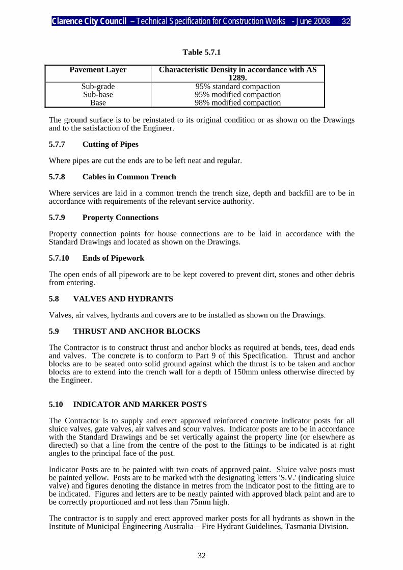
Table 5.7.1
Pavement Layer Characteristic Density in accordance with AS 1289.
Sub-grade Sub-base
Base
95% standard compaction 95% modified compaction 98% modified compaction
The ground surface is to be reinstated to its original condition or as shown on the Drawings and to the satisfaction of the Engineer. 5.7.7 Cutting of Pipes Where pipes are cut the ends are to be left neat and regular. 5.7.8 Cables in Common Trench Where services are laid in a common trench the trench size, depth and backfill are to be in accordance with requirements of the relevant service authority. 5.7.9 Property Connections Property connection points for house connections are to be laid in accordance with the Standard Drawings and located as shown on the Drawings. 5.7.10 Ends of Pipework The open ends of all pipework are to be kept covered to prevent dirt, stones and other debris from entering. 5.8 VALVES AND HYDRANTS Valves, air valves, hydrants and covers are to be installed as shown on the Drawings. 5.9 THRUST AND ANCHOR BLOCKS The Contractor is to construct thrust and anchor blocks as required at bends, tees, dead ends and valves. The concrete is to conform to Part 9 of this Specification. Thrust and anchor blocks are to be seated onto solid ground against which the thrust is to be taken and anchor blocks are to extend into the trench wall for a depth of 150mm unless otherwise directed by the Engineer. 5.10 INDICATOR AND MARKER POSTS The Contractor is to supply and erect approved reinforced concrete indicator posts for all sluice valves, gate valves, air valves and scour valves. Indicator posts are to be in accordance with the Standard Drawings and be set vertically against the property line (or elsewhere as directed) so that a line from the centre of the post to the fittings to be indicated is at right angles to the principal face of the post. Indicator Posts are to be painted with two coats of approved paint. Sluice valve posts must be painted yellow. Posts are to be marked with the designating letters 'S.V.' (indicating sluice valve) and figures denoting the distance in metres from the indicator post to the fitting are to be indicated. Figures and letters are to be neatly painted with approved black paint and are to be correctly proportioned and not less than 75mm high. The contractor is to supply and erect approved marker posts for all hydrants as shown in the Institute of Municipal Engineering Australia – Fire Hydrant Guidelines, Tasmania Division.
Clarence City Council – Technical Specification for Construction Works - June 2008 33
33
5.11 INSPECTIONS Unless otherwise required by the Engineer the Contractor is to arrange for inspections to be carried out at the following stages of the work:
a) Completion of trench excavation prior to placement of bedding material. b) Completion of bedding material prior to actual laying of pipes. c) Completion of pipe laying prior to any backfilling. d) Testing of pipelines. e) Stages of backfilling. f) Completion of work at Practical Completion. g) Final inspection after Defects Liability Period.
Twenty four (24) hours notice is required for any of the above inspections. Work must not proceed unless each stage of work has been inspected and passed by the Engineer. 5.12 TESTING 5.12.1 Cost of Testing All tests required by the Engineer are to be at the Contractor’s expense. 5.12.2 Testing of Bedding, Haunching and Backfill Material The Engineer may request a sample of bedding or backfill material to be taken and tested by a registered N.A.T.A. testing laboratory in order to determine whether the material complies with this specification. Any material which is found not to comply with the requirements must not be used for bedding or backfill. 5.12.3 Pipeline Inspection and Testing
a) Flushing. The pipeline must be flushed clean prior to testing. b) Pipeline Testing All lines must be tested in the presence of the Engineer to a pressure of 1500kPa in
accordance with the appropriate Australian Standard. Each line is to be tested after it has been laid and jointed and sufficient filling has been placed over the centre of each pipe to hold it in position except at the joints. No line is to be tested less than forty eight (48) hours after construction of all thrust blocks and anchors.
The Contractor is to provide a 20mm tapping and ferrule tap or other suitable
approved means for connecting the line to be tested. Such tapping is to be provided, where directed, for each section of water main to be separately tested.
5.12.4 Backflow Prevention Device Inspection and Testing.
Must comply to Section 4 of AS3500.1 and must be tested by a qualified backflow prevention device tester prior to practical completion.
Clarence City Council – Technical Specification for Construction Works - June 2008 34
34
TECHNICAL SPECIFICATION FOR CONSTRUCTION WORKS
PART 6
MATERIAL AND PAVEMENT CONSTRUCTION
I N D E X
CLAUSE TITLE 6.1 SCOPE OF WORK 6.2 STANDARDS 6.3 MATERIALS 6.3.1 GENERAL 6.3.2 SOURCE OF MATERIALS 6.3.3 CRUSHED AGGREGATE 6.3.4 SHOULDER MATERIAL 6.3.5 WATER 6.3.6 WET MIX 6.4 CONSTRUCTION 6.4.1 SPREADING OF MATERIALS 6.4.2 COMPACTION OF MATERIALS 6.4.3 CONSTRUCTION TOLERANCES 6.5 INSITU STABILISATION 6.5.1 GENERAL 6.5.2 SAFETY 6.5.3 DESCRIPTION 6.5.4 MATERIALS 6.5.5 CONTRACTOR’S PERSONNEL & EQUIPMENT 6.5.6 INITIAL SURFACE PREPARATION AND MILLING 6.5.7 SPREADING OF BINDER 6.5.8 MIXING 6.5.9 MOISTURE CONTENT

Clarence City Council – Technical Specification for Construction Works - June 2008 35
35
TECHNICAL SPECIFICATION FOR CONSTRUCTION WORKS
PART 6
MATERIAL AND PAVEMENT CONSTRUCTION
I N D E X cont.
CLAUSE TITLE 6.5.10 COMPACTION 6.5.11 FINISHING 6.5.12 CURING 6.5.13 SAMPLING AND TESTING 6.6 ACCEPTANCE 6.6.1 INSPECTION 6.6.2 TESTING

Clarence City Council – Technical Specification for Construction Works - June 2008 36
36
6.1 SCOPE OF WORK This section includes the supply of all materials, equipment, labour and services necessary for the construction of pavements. 6.2 STANDARDS The following Australian Standards and Standard Drawings are referred to: Australian Standards AS 1141 Methods of Sampling and Testing Aggregates. AS 1289 Methods of Testing Soil for Engineering Purposes. AS 1348.1 Road and Traffic Engineering - Glossary of Terms. Standard Drawings MSD 1-08A Urban Road (Typical Cross Section). MSD 2-01 Rural Road (Typical Cross Section). 6.3 MATERIALS 6.3.1 General Unless otherwise specified, all pavement material is to be crushed aggregate produced from sound unweathered igneous rock and shoulder material is to be natural gravel. 6.3.2 Source of Materials The Contractor is to identify the source of materials and may be required to provide N.A.T.A. endorsed certificates plus a 20kg representative sample at least three (3) days prior to use for approval by the Engineer. Changes to the material source must be approved by the Engineer. 6.3.3 Crushed Aggregate
a) Base Course Material. Base course material is to be crushed aggregate with grading conforming with
Table 6.3.1, with a Plasticity Index not greater than 6, a Liquid Limit not greater than 25 and have a Los Angeles Abrasion Test value not greater than 35.
b) Sub-base Materials. Sub-base materials are to be crushed aggregate with grading conforming to Table
6.3.1, with a Plasticity Index not greater than 12 a Liquid Limit not greater than 30 and a Los Angeles Abrasion Test value not greater than 35.

Clarence City Council – Technical Specification for Construction Works - June 2008 37
37
Table 6.3.1
Sieve Size (mm) Class of Material Sub-base Course Base Course
53 37.5 26.5 19 9.5 4.75 2.36 0.425 0.075
100 95 - 100 90 - 100 78 - 100 54 - 78 37 - 62 27 - 48 13 - 24 6 - 13
100 95 - 100 62 - 86 43 - 67 32 - 52 15 - 26 7 - 14
6.3.4 Shoulder Material Shoulder material is to be natural gravel with grading conforming to Table 6.3.2, a Plasticity Index of 10-15 and a Liquid Limit not greater than 35.
Table 6.3.2
A.S. Sieve Size (mm) Percentage Passing 37.5 26.5 19.0 9.50 4.75 2.36 0.425 0.075
100 85 - 100 75 - 100 64 - 100 45 - 90 30 - 73 16 - 39 9 - 22
6.3.5 Water The water used is to be clear, clean and free of deleterious substances. 6.3.6 Wet Mix Wet mix is to consist of a uniform blend of base course material and water to provide a uniform moisture content of 3 to 7 percent. The actual water content is to be as recommended by the Superintendent and approved by the Engineer. The aggregate and water are to be mixed by a central mixing plant in a mixer approved by the Engineer. Discharge from the mixer into delivery trucks must be effected in such a manner as to avoid segregation.

Clarence City Council – Technical Specification for Construction Works - June 2008 38
38
6.4 CONSTRUCTION 6.4.1 Spreading of Materials Materials are to be spread uniformly and in layers not exceeding 150mm loose depth in a manner which avoids segregation. 6.4.2 Compaction of Materials The sub-base material and shoulder material must be compacted to a minimum characteristic dry density ratio of 95 per cent of modified compaction at optimum moisture content. The base course material is to be compacted to a minimum characteristic dry density ratio of 98 per cent of modified compaction at optimum moisture content. Compaction of each layer is to commence immediately using a smooth wheeled roller of minimum static mass of 10 tonne or approved equivalent. Water is to be added and must be thoroughly mixed to give the required moisture content through the depth of the layer. Material with excess moisture is to be dried to the required moisture content. Each pass of the compaction plant is to be parallel with the centreline of the pavement. On sections having one-way crossfall, compaction is to start at the lower edge and progress towards the higher edge. On crowned sections, compaction is to start at the outer edges and progress towards the crown. The method of compaction is to allow for 300mm minimum overlap between passes. 6.4.3 Construction Tolerances Each pavement course, consisting of one or more layers of the same material, is to be finished to a smooth and uniform surface and must conform to the levels, grades and shapes shown on the Drawings. The finished surface of the sub-base is to be within +20mm of the designated levels and when measured with a 3.0 metre straight edge laid in any direction on the surface, the deviation of the surface from the straight edge must not exceed 25mm. The finished surface of the base is to be within +10mm of the designated levels and when measured with a 3.0 metre straight edge laid in any direction of the surface, the deviation of the surface from the straight edge must not exceed 15mm. Any departures in excess of the requirements for finished surface must be corrected by scarifying the layer concerned, removing excess or adding deficient pavement material, as required and recompacting the area to a uniform surface.

Clarence City Council – Technical Specification for Construction Works - June 2008 39
39
6.5 INSITU STABILISATION This clause is based upon the AusStab Model Specification for Insitu Stabilisation of Local Government Roads using Cementitious Binders including Lime {Version A – 1998]. Where specified in the design documentation pavement material is to be stabilised with the nominated type and amount of cementitious binder in accordance with this clause. 6.5.1 General Incorporation of the binder shall be accomplished using a purpose built stabilising mixer with mixing box referred to as a "stabiliser". The Contractor is to confirm that all services have adequate clearance to the area to be stabilised before stabilisation commences. 6.5.2 Safety The Contractor is responsible for minimising dust nuisance from his operations. This is to include the use of dust suppression equipment on binder spreaders, suitable control of traffic and limiting the work to days free of excessive wind. The Contractor is to ensure that his personnel are issued with and are making use of appropriate personal protective equipment at all times. As a minimum this shall include safety boots, high visibility vests and hearing protection issued to all personnel and overalls, gloves, dust mask and eye protection for those personnel coming into contact with free cement or lime. The Contractor shall also ensure that one member of the stabilising crew is issued with a first aid kit suitable for the work undertaken. 6.5.3 Description The stabilised pavement is to be composed of a combination of soil and binder uniformly mixed, moistened and compacted in accordance with this specification and shaped to conform to the lines, grades, thicknesses and typical cross-sections shown on the plans, or as directed by the Engineer. Stabilisation is to be undertaken by using the equipment described in this specification with a minimum of two mixing operations to ensure sufficient uniformity of the binder in the pavement material. The stabilised pavement is to be cured prior to sealing.

Clarence City Council – Technical Specification for Construction Works - June 2008 40
40
6.5.4 Materials
a) Binder All binders shall be supplied by the Contractor, and shall be of Australian manufacture and comply with the following Australian Standards:
Binder Australian Standard GP & GB Cement AS 3972 Lime AS4889.1 Fly ash AS3582.1 Slag AS3582.2
When required by the Engineer, documentary or other acceptable evidence of the quality of the binder shall be furnished by the Contractor, and any binder that is not satisfactory shall be rejected.
b) Water The water used for the modification work must be potable and free from any substance which could cause blockage of jets in the stabiliser.
6.5.5 Contractor’s Personnel and Equipment The Contractor’s staff must be suitably experienced in stabilisation operations and is to include at least one Professional Engineer capable of providing the necessary technical support to the operations. The equipment must be purpose built for the necessary tasks, satisfying the requirements of the Specification and shall be maintained in excellent mechanical condition. 6.5.6 Initial Surface Preparation and Milling Machinery used for reclamation of the pavement is to be capable of pulverising asphalt to depths of up to 150 mm and to a nominal size of 40 mm. Where, in the opinion of the Engineer, it is necessary, the surface of the insitu material is to be proof rolled to reveal any irregularities in the surface of the material, and to allow the stabilising equipment to traverse the area without excessive displacement of the surface. The surface is then to be trimmed to the required alignment, levels and cross-sections necessary to produce the required final compacted thickness of stabilised material. Where a conventional stabiliser is used, the insitu material is to be given a preliminary ripping to a depth not exceeding the depth of stabilisation, to assist the cutting and pulverising action of the stabiliser. If thick in-fill layers of asphalt have been identified the Contractor is to mill the asphalt and evenly spread the milled asphalt onto the surface of the existing pavement to minimise the need for imported granular material.
Clarence City Council – Technical Specification for Construction Works - June 2008 41
41
6.5.7 Spreading of Binder Spreading equipment used for spreading binder must be capable of being pneumatically filled on site. The machinery is to have a rigid cover and other measures to prevent dust generation during handling. The binder is to be uniformly spread at a controlled weight by area rate (kg/m2 ) across the pavement. The rate of spreading is to provide the specified binder content in the compacted material. The spreader is to be equipped with gates to allow variable widths of binders to be deposited onto the pavement surface. The contractor is to record the area of spread, tonnage of binder used per run, and mat or tray results at the frequencies specified in clause 6.5.13 (b), and keep these records for at least 12-months after completion of the project. The construction tolerance for the spread rate is to be better than 10%. Once the binder has been spread, the only traffic that is to travel over the area to be stabilised is to be construction plant employed for the stabilisation work. GP cement is not to be spread on the road in excess of two hours prior to incorporation into the pavement. If the binder is quicklime slaking is to be completed before mixing. 6.5.8 Mixing The total specified quantity of binder required for the full depth of the treatment is to be uniformly spread over the surface to be treated prior to the mixing process, or incorporated in the pavement by an approved controlled mechanical feed, in one operation, in a manner satisfactory to the Engineer. No equipment except that used in spreading and mixing will be allowed to pass over the freshly spread binder until mixing operations are complete. Water is to be added during the mixing process by means of a controlled pressure feed distributor located inside the mixing chamber and the quantity applied is to be such that the materials in the pavement are brought to the required moisture content as determined by the Engineer. The moisture content is to be uniformly distributed through the pavement material. The water additive system is to be capable of delivering a controlled quantity of water per unit area irrespective of ground speed and is to be capable of automatically stopping the water flow when the stabiliser stops moving. The stabiliser is to be capable of maintaining a constant rotor speed irrespective of ground conditions. The stabiliser is to be capable of mixing to a depth of at least 250 mm in a single pass. The stabiliser is to be capable of automatically maintaining a preset uniform depth of cut without operator input and is to be designed such that the position of the rotor in the cut is not effected by pitching or other unforseen movements of the stabiliser. The mixing equipment is to be so constructed and operated that the compacted depth of stabilised pavement is to be to the specified full depth. Mixing using graders, profilers, rotary hoes and other agricultural type implements will not be approved for stabilisation work.
Clarence City Council – Technical Specification for Construction Works - June 2008 42
42
For GP, GB and most cement blends, two passes of the stabiliser are to be performed to obtain an even mixture of the binder throughout the pavement depth. Where lime is used the lime, soil and water is to be rotary mixed to achieve even distribution through the full depth of the layer being stabilised. A minimum of two passes of the stabiliser is required unless directed otherwise by the Engineer. The Engineer may reduce the number of passes required if, in the first pass, mixing reduces the clay clods so that they are broken down to pass a 26.5 mm screen and at least 60% pass a 4 mm screen, exclusive of any non-slaking. After mixing, the lime treated layer is to be promptly graded to shape and compacted. Compaction is to begin immediately after final mixing when the moisture content of the processed layer is at optimum. If, due to weather conditions, plant breakdown or other causes, the binder cannot be uniformly incorporated in the pavement in accordance with the above procedure before becoming damp, then additional binder is to be spread before final mixing. The rate of binder is a function of the time interval and the binder type, with slower setting binders providing greater flexibility. Mixing is to proceed in lanes working from one side of the pavement to the other, without intervening lanes of unmixed material. 6.5.9 Moisture Content The moisture content of the material immediately after mixing shall be 80% to 110% of the moisture content specified by the Engineer and not greater than the optimum moisture content. 6.5.10 Compaction Compaction of the material in the pavement is to commence within thirty [30] minutes after the addition of water to the mix. Initial compaction, after mixing shall be carried out by a smooth steel drum or pad-foot roller with an equivalent static weight of between 8 and 16 tonnes consistent with the degree of compaction and vibration risks associated with each site. The compaction achieved, as determined by tests of the insitu material, shall not be less than 95% of the maximum dry density determined by comparison of the results of AS1289.5.1.1 & AS1289.5.3.1.

Clarence City Council – Technical Specification for Construction Works - June 2008 43
43
6.5.11 Finishing The finished surfaces shall be true to line and level, with correct crossfall, and free from loose pockets, holes, bumps and flakes of material. The pavement surface is to be finished to a straight uniform profile from crown of pavement to the lip of gutter in the case of full width stabilisation. The finished stabilised pavement must not vary by more than 10mm in any direction when tested with a 3m straight edge. Where shoulders only are to be stabilised, the finished profile is to comprise a straight uniform crossfall from the edge of the existing pavement to the outer edge of the construction. All final trimming is to be cut to waste or reused in other applications as directed by the Engineer. 6.5.12 Curing The stabilised pavement must be protected from moisture loss for a period of 4 days or until a wearing surface or further pavement layer is applied; whichever the earliest. This curing may be attained by: a) keeping the pavement damp by means of water spray; or b) applying a sprayed bituminous curing membrane consisting of either a rapid-setting
bitumen emulsion or a cutback bitumen within 24 hours of the finishing operations. The Contractor is to carry out the necessary curing works. 6.5.13 Sampling and Testing
a) General The Contractor is to make available equipment and a trained Soils Technician to carry out moisture, compaction control or other specified tests as required by the Engineer. The Contractor is to submit with the tender unit prices for this service and those noted below.
b) Spread Rate
The spread rate is to be verified as per AustStab National Guidelines at least once per hour or once per four tonnes whichever is the lesser or as directed by the Engineer.
Clarence City Council – Technical Specification for Construction Works - June 2008 44
44
c) Depth The depth of stabilisation shall be verified by measuring the depth of “cutting” adjacent to an existing pavement material in at least two locations within the street and measured to the nearest 5 mm. The construction tolerance for the stabilised and compacted depth is +/-10mm.
d) Density The density of stabilisation is to be verified by testing in at least two locations within the street in accordance with AS1289.5.1.1 & AS1289.5.3.1.
e) Other Tests Other tests, such as UCS and moisture content, are to be carried as direct by the Engineer at the Principal’s expense.
6.6 ACCEPTANCE 6.6.1 Inspection The Contractor is responsible for arranging inspection by the Engineer of the various stages of the work. The following inspections are required:
a) Inspection of the subgrade prior to commencing pavement construction. b) Completion of each layer of the pavement.
Twenty-four (24) hours notice is required for each inspection. Work must not proceed unless each stage of the work is passed by the Engineer. 6.6.2 Testing
a) Materials Testing. The Engineer may direct the Contractor to supply to the Engineer copies of
delivery dockets for all pavement material used. The Engineer may direct the Contractor to test the materials supplied in accordance with this specification. The requested tests are to be conducted by an approved N.A.T.A. laboratory at a rate of three (3) tests from each 1,000 tonnes of material supplied or part thereof, as directed by the Engineer. Cost of testing is to be met by the Contractor.
b) Pavement Testing. All pavement layers are to be compacted so that they are capable of withstanding
proof rolling, without visible deformation or springing with a smooth wheeled roller of approximately 8-10 tonnes static mass or a single rear axle truck fitted with dual wheels and 9.00 x 20 tyres inflated to 550 kPa loaded to produce a rear axle mass of 8.2 tonne, or such other vehicle as may be approved by the Engineer, travelling at 4 to 5 kph. Unstable areas detected by proof rolling are to be rectified by the Contractor using methods approved by the Engineer.

Clarence City Council – Technical Specification for Construction Works - June 2008 45
45
TECHNICAL SPECIFICATION FOR CONSTRUCTION WORKS
PART 7
CONCRETE KERB AND CHANNEL
I N D E X
CLAUSE TITLE 7.1 SCOPE OF WORK 7.2 STANDARDS 7.3 MATERIALS 7.3.1 READY-MIXED CONCRETE 7.3.2 MORTAR 7.4 PROFILES 7.5 PLACING 7.5.1 BASE PREPARATION 7.5.2 POURING 7.5.3 FORMWORK 7.5.4 JOINTS 7.5.5 SURFACE FINISH 7.5.6 PRE-CAST UNITS 7.6 PROTECTION AND CURING 7.6.1 PROTECTION 7.6.2 CURING 7.7 ACCEPTANCE 7.7.1 INSPECTIONS 7.7.2 TOLERANCES

Clarence City Council – Technical Specification for Construction Works - June 2008 46
46
7.1 SCOPE OF WORK This section includes the supply and delivery of materials, labour and services necessary for the construction of manually-placed or machine-placed insitu and pre - cast concrete kerb and channel. 7.2 STANDARDS The following Australian Standards and Standard Drawings are referred to: Australian Standards AS 3972 Portland and Blended Cements. AS 2758.1 Aggregates and Rock for Engineering Purposes.
AS 2876 Concrete Kerb and Channels (Gutters) - Manually or Machine Placed. Standard Drawings MSD 1-02A Kerb and Channel Profiles. MSD 1-06C Kerb Ramps. MSD 1-07 Vehicle Crossing (Urban Residential). 7.3 MATERIALS 7.3.1 Ready-mixed Concrete Concrete used in the construction of in-situ kerb and channel is to be ready-mixed concrete manufactured and supplied by a concrete manufacturer in accordance with Part 9 of this specification. Manually-placed concrete is to be normal grade N20 concrete and must have the following properties:
a) Minimum strength 20 MPa. b) Maximum aggregate size 20 mm. c) Maximum slump 60 +/-15 mm.
Machine-placed concrete is to be Special-Class (S20) and must have the following properties:
a) Minimum strength 20 MPa. b) Maximum aggregate size 20 mm. c) Maximum slump 20 mm. d) Minimum cement content 280 kg/m3.
Clarence City Council – Technical Specification for Construction Works - June 2008 47
47
The concrete must be mixed with sufficient water to produce a consistency which maintains the design profile after extrusion. The combined aggregate grading is to be arranged so that not more than 80 per cent passes the 6.7mm AS sieve. 7.3.2 Mortar Mortar for finishing is to consist of not less than one (1) part cement to three (3) parts of sand, metal dust or an approved equivalent, by loose pour volume. The water quantity is to be just sufficient to obtain thorough mixing and adequate workability.
a) Cement. Cement is to be Type A Portland cement complying with AS 1315. b) Sand. Sand is to be composed of sharp tough grains, free of mica, clay or foreign matter
and is to be in accordance with AS 2758 Part 1. c) Water. Water for use in mortar shall be clean and free of all substances harmful to
concrete and reinforcing steel. d) Bedding. The bedding material is to consist of sub-base material in accordance with Part 6 of
this specification, Material and Pavement Construction.
7.4 PROFILES The selection and position of the kerb and channel is to be in accordance with the Drawings. Kerb and channel profiles are to be in accordance with Standard Drawings or as otherwise shown on the Drawings. 7.5 PLACING Construction is to be in accordance with Part 9 of this specification and the following clauses. 7.5.1 Base Preparation
a) New Pavement. All kerb and channel is to be bedded on an extension of the road pavement, which
shall be equal in thickness to the depth of the pavement, but is not to be less than 75mm. The bedding is to be placed and compacted in accordance with AS 2876. The bedding is to be lightly watered and dowels for joints are to be available on site and fixed in place where necessary.
Clarence City Council – Technical Specification for Construction Works - June 2008 48
48
b) Existing Pavement. The excavation for bedding for kerb and channel is to be to the depth of the
existing pavement and in any case is to be to a minimum of 75mm below the base of the kerb and channel. Excavation is to extend 500mm into the existing pavement from the face of kerb or invert of channels, and 150mm behind the back of the kerb or channel.
The sides of the excavation are to extend at an inclination of 45 degrees beyond
these limits. The bedding is to be placed and prepared in accordance with Clause 7.5.1 (a). c) Pre-cast Kerbing. Where pre-cast kerb is to be installed on the top of the pavement, it is to be swept
clear of dust and loose stone prior to installation.
7.5.2 Pouring Kerb and channel is to be poured to the specified line, level and minimum grade as shown on the Drawings or as directed by the Engineer. Pouring of the kerb is to generally be carried out using a self propelled kerb and channel paving machine designed to compact and extrude the final profile and capable of automatically adjusting the mould position while in operation. Manually-placed concrete is to be placed in bays of 3.0 metres in length. 7.5.3 Formwork Templates of the finished shape and profile are to be provided at 3.0 metre centres. Forms are to be firmly held in place and capable of easy release and removal. End forms are to be provided at the end of each pour. 7.5.4 Joints Joints are to be located as shown on the Drawings and are to be formed in accordance with AS 2876. Unless otherwise approved by the Engineer, contraction or shrinkage control joints are to be cut in machine laid kerb and channel at 3.0 metre centres using a template and the joints finished with a suitable grooving tool. R10 mild steel dowels are to be inserted into the back of the kerb at 1.0 metre centres in accordance with Standard Drawings MSD 1-03A and MSD 1-04A, where concrete footpath is to be laid adjacent to the kerb.

Clarence City Council – Technical Specification for Construction Works - June 2008 49
49
7.5.5 Surface Finish All kerb and channel is to be finished to a smooth steel trowel finish in accordance with AS 2876. Machine-placed kerb and channel is to be rendered with a mortar in accordance with AS 2876. 7.5.6 Pre-cast Units Pre-cast units are to be installed by spiking through each unit or tags cast into it, using 2 spikes of at least 10 mm. diameter, driven at least 100 mm. into the underlying pavement, or when approved by the Engineer, by proprietary adhesive applied in accordance with the manufacturer's instructions. 7.6 PROTECTION AND CURING 7.6.1 Protection Newly finished concrete surfaces must be protected from premature drying and damage by rain, frost or vandalism for a period of twenty-four (24) hours after pouring. Appropriate signs, barricades and lights must be erected to protect the newly-laid work from traffic, and to protect the public from injury. 7.6.2 Curing Concrete is to be cured by covering with hessian kept wet for a period of not less than seven (7) days, or by other methods as approved by the Engineer. 7.7 ACCEPTANCE 7.7.1 Inspections Inspection, sampling and testing of the concrete is to be carried out in accordance with AS 2876. The contractor must notify the Engineer to allow inspection of the following stages of the work:
a) Preparation of the sub-grade; b) Compaction of the base and set-out of the kerb and channel alignment prior to
pouring; c) Completion of the work.
The Engineer may inspect the laying of the concrete and is to reject any concrete that has not the correct property, texture, depth, shape or level. .7.2 Tolerances

Clarence City Council – Technical Specification for Construction Works - June 2008 50
50
Unless otherwise specifically permitted in writing by the Engineer, the tolerances on the concrete mix and construction are to be in accordance with AS 2876.

Clarence City Council – Technical Specification for Construction Works - June 2008 51
51
TECHNICAL SPECIFICATION FOR CONSTRUCTION WORKS
PART 8
FOOTPATH CONCRETE
I N D E X
CLAUSE TITLE 8.1 SCOPE OF WORK 8.2 STANDARDS 8.3 MATERIALS 8.3.1 CONCRETE MATERIALS 8.3.2 BEDDING 8.3.3 STEEL REINFORCING FABRIC 8.4 CONSTRUCTION 8.4.1 SUBGRADE FORMATION 8.4.2 BEDDING 8.4.3 FORMWORK 8.4.4 REINFORCEMENT 8.4.5 CONCRETE WORK 8.5 ACCEPTANCE 8.5.1 INSPECTION 8.5.2 TESTING 8.5.3 TOLERANCES
Clarence City Council – Technical Specification for Construction Works - June 2008 52
52
8.1 SCOPE OF WORK This part of the specification includes the supply of all materials, equipment, labour and services necessary for the construction of reinforced concrete footpaths. 8.2 STANDARDS The following Australian Standards and Standard Drawings are referred to: Australian Standards AS 1304 Hard-Drawn Steel Wire Reinforcing Fabric for Concrete Standard Drawings MSD 1-04A Reinforced Concrete Footpath MSD 1-06C Kerb Ramps MSD 1-07 Vehicle Crossing (Urban Residential) 8.3 MATERIALS 8.3.1 Concrete Materials All concrete materials are to be in accordance with Part 9 of this specification, Construction of Minor Concrete Structures. 8.3.2 Bedding Bedding material is to be in accordance with Part 6 of this specification, Material and Pavement Construction. 8.3.3 Steel Reinforcing Fabric All steel reinforcing fabric must comply with the requirements of AS1304. 8.4 CONSTRUCTION 8.4.1 Subgrade Formation The subgrade must be formed in accordance with Part 2 of this specification, Earthworks. 8.4.2 Bedding Bedding material is to be placed and compacted as shown on drawings MSD 1-04A and MSD 1-07, in accordance with Part 6 of this specification, Material and Pavement Construction.
Clarence City Council – Technical Specification for Construction Works - June 2008 53
53
8.4.3 Formwork The construction, use and removal of all formwork is to be in accordance with Part 9 of this specification, Construction of Minor Concrete Structures. 8.4.4 Reinforcement Steel reinforcing bars and fabric are to be placed as shown on drawing MSD 1-04A. Bar chairs are to be provided to support all reinforcement at 1.0 metre maximum spacings. 8.4.5 Concrete Work Concrete work is to be in accordance with drawings MSD 1-04A, MSD 1-06C, MSD 1-07 and Part 9 of this specification, Construction of Minor Concrete Structures. The surface finish is to be a broomed non-slip finish. 8.5 ACCEPTANCE 8.5.1 Inspection The Contractor is responsible for arranging inspections by the Engineer of the various stages of the work as follows:
a) Inspection of the site prior to commencement of the works. b) Completion of the subgrade formation prior to construction of the bedding. c) Completion of construction of the bedding prior to placement of reinforcement and
formwork. d) Completion of placement of reinforcement and formwork prior to pouring
concrete. e) Completion of the work.
24 hours notice is required for any of the above inspections. Work is not to proceed unless the Engineer passes each stage. 8.5.2 Testing Testing of the subgrade formation, bedding material and concrete work is to be in accordance with Part 6 of this specification, Material and Pavement Construction, and Part 9 of this specification, Construction of Minor Concrete Structures.

Clarence City Council – Technical Specification for Construction Works - June 2008 54
54
8.5.3 Tolerances a) The finished thickness of the concrete footpath is to be as shown on the drawings and
must be within a tolerance of +5mm to +0mm. The finished crossfall of the footpath must not deviate by more than 5mm from the design level change.
b) The finished width of the concrete footpath must be within a tolerance of +5mm to -
5mm from the design width. c) Footpath located against the kerb is to match the finished top of kerb level.
d) Footpath located elsewhere must not deviate from the finished design level by more than +20mm.

Clarence City Council – Technical Specification for Construction Works - June 2008 55
55
TECHNICAL SPECIFICATION FOR CONSTRUCTION WORKS
PART 9
CONSTRUCTION OF MINOR CONCRETE STRUCTURES
I N D E X
CLAUSE TITLE 9.1 SCOPE OF WORK 9.2 STANDARDS 9.3 MATERIALS 9.4 CONCRETE MIX DESIGN 9.5 CONCRETE MANUFACTURE 9.6 CONSTRUCTION 9.6.1 FOUNDATION 9.6.2 FORMWORK 9.6.3 REINFORCEMENT 9.6.4 CONCRETE PLACEMENT, SURFACE CURING AND FINISH 9.7 ACCEPTANCE 9.7.1 INSPECTION 9.7.2 SAMPLING AND TESTING 9.7.3 ACCEPTANCE OF CONCRETE
Clarence City Council – Technical Specification for Construction Works - June 2008 56
56
9.1 SCOPE OF WORK This section includes the supply of materials, equipment, labour and services necessary for the construction of minor concrete structures including pits, access chambers, anchor blocks, minor walls, footpaths, pavements and vehicular crossings. 9.2 STANDARDS The following Australian Standards are referred to: Australian Standards AS 1012 Methods of Testing Concrete AS 1141 Methods of Sampling and Testing Aggregates AS 1302 Steel Reinforcing Bars for Concrete AS 1303 Steel Reinforcing Wire for Concrete AS 1304 Welded Wire Reinforcing Fabric for Concrete AS 1379 The Specification and Manufacture of Concrete AS 1478 Chemical Admixtures for use in Concrete AS 1509 Formwork for Concrete AS 2758.1 Concrete Aggregates AS 3600 Concrete Structures AS 3972 Portland and Blended Cements 9.3 MATERIALS Water is to be free of all substances harmful to concrete and reinforcing steel. Cement is to be Portland Cement Type A unless otherwise shown on the Drawings and bedding is to be base course in accordance with Part 6 of this specification, Material and Pavement Construction. 9.4 CONCRETE MIX DESIGN Unless otherwise specified concrete is to be normal grade and have the following properties:
a) Minimum Strength 20 MPa b) Maximum Aggregate Size 20 mm c) Maximum Slump 80 mm
The Contractor is responsible for the design of the concrete mix required to attain the specified concrete requirements. The use of chemical admixtures and fly ash is to only be used with the prior direction or approval of the Engineer.
Clarence City Council – Technical Specification for Construction Works - June 2008 57
57
9.5 CONCRETE MANUFACTURE All concrete is to be ready-mixed concrete from an approved mixing plant. 9.6 CONSTRUCTION 9.6.1 Foundation Excavations and embankments are to be formed and compacted to the lines, levels and grades shown on the Drawings or as directed by the Superintendent. Organic and soft material forming part of the subgrade is to be removed and replaced with suitable material compacted in layers not exceeding 150mm, measured loose prior to compaction, and bedding spread and compacted as shown on the Drawings. 9.6.2 Formwork Forms are to be of approved material, rigid, securely braced and supported to produce mortar tight joints and smooth even surfaces. Interior surfaces of forms are to be thoroughly cleaned and oiled before erection. 9.6.3 Reinforcement Reinforcement is to be placed in accordance with the reinforcement details as shown on the Drawings. Approved chairs, spacers and other supports are to be used for the support of all reinforcement. Reinforcing steel fabric is to be supported and held in position with approved supports spaced at one (1) metre intervals in each direction. Reinforcing bars are to be placed in the positions indicated in the Drawings and held with 1.6mm wire ties at each intersection and sufficient chairs and spacers to prevent movement. Cover is to be as specified on the Drawings or as directed by the Superintendent. 9.6.4 Concrete Placement, Surface Curing and Finish Concrete must not be placed until all formwork, installation of reinforcement and preparation of all surfaces have been approved by the Engineer. Except with approval of the Engineer, concrete must be placed in dry conditions and only in such quantities as are required for immediate use and must be placed before initial set has occurred.
Clarence City Council – Technical Specification for Construction Works - June 2008 58
58
Concrete must be placed so as to avoid segregation and in layers not exceeding 300mm depth and shall be thoroughly compacted during and immediately after placing by means of continuing tamping, spading or use of vibrators, as directed by the Engineer. Under no circumstances is concrete to be shaken, displaced or disturbed after the initial set of the concrete. After placement of the concrete, exposed surfaces are to be kept continuously wet for a minimum period of seven (7) days by covering with water saturated material. New surfaces are to be protected from rain damage until hard set has occurred. Except as otherwise directed, formwork is to be removed after a period of not less than twenty-four (24) hours after concrete pouring. Formed concrete is to have a smooth finish and be free from blowholes, voids and honeycomb. Top surfaces are to be finished with a steel trowel and have tooled edges, with slabs having a broomed surface if required by the Engineer. Any defective concrete must be repaired as directed within twenty-four (24) hours of formwork removal. 9.7 ACCEPTANCE 9.7.1 Inspection The Contractor is to arrange for the following inspections:
a) Formation or excavation prior to placement of bedding material. b) Bedding construction prior to placement of reinforcement. c) Placement of reinforcement and formwork prior to pouring of concrete. d) Completion of work.
Twenty-four (24) hours notice is required for any of the above inspections. Work must not proceed until each stage has been approved by the Engineer. 9.7.2 Sampling and Testing Sampling and testing of concrete is to be as requested by the Engineer. The making, handling, caring, storage, transportation and testing of the samples is to be by a N.A.T.A. testing laboratory approved by the Engineer. All testing of concrete is to be carried out in accordance with AS 1012, Australian Standard Methods of Sampling and Testing.
Clarence City Council – Technical Specification for Construction Works - June 2008 59
59
9.7.3 Acceptance of Concrete The Engineer may reject concrete at the site of placement where:
a) The slump tests fail to meet the requirements of AS 1379, Clause 3.1. b) More than one and a half hours, has elapsed after the introduction of the mixing
water to the cement and aggregate.
Clarence City Council – Technical Specification for Construction Works - June 2008 60
60
TECHNICAL SPECIFICATION FOR CONSTRUCTION WORKS
PART 10
SEALING
I N D E X
CLAUSE TITLE 10.1 SCOPE OF WORK 10.2 STANDARDS 10.3 MATERIALS 10.3.1 AGGREGATE 10.3.2 BINDER 10.3.3 PRIMER 10.3.4 PRIMER-BINDER 10.4 PREPARATION 10.4.1 PROTECTION OF OTHER WORKS 10.4.2 SURFACE PREPARATION 10.4.3 PRE-COATING 10.4.4 PROVISION FOR TRAFFIC 10.5 SEALING 10.5.1 ORGANISATION OF THE WORK 10.5.2 APPLICATION RATES 10.5.3 SPRAYERS 10.5.4 TEMPERATURE 10.5.5 PRIMING 10.5.6 PRIMER-BINDER AND BINDER 10.6 SPREADING AGGREGATE 10.6.1 AGGREGATE SPREADERS 10.6.2 APPLICATION 10.7 COMPACTION 10.7.1 COMPACTION PLANT 10.7.2 COMPACTION 10.7.3 REMOVAL OF LOOSE AGGREGATE 10.8 ACCEPTANCE
Clarence City Council – Technical Specification for Construction Works - June 2008 61
61
10.1 SCOPE OF WORK This section covers the supply and delivery of all materials, labour and plant necessary for bituminous priming and sealing of the road surface. 10.2 STANDARDS The following Australian Standards are referred to:
Australian Standards AS 2008 Residual Bitumen For Pavements AS 1742.3 Traffic Control Devices For Works on Roads AS 2341 Methods of Testing Bitumen and Related Road-making Products AS 2758.2 Aggregates for Sprayed Bituminous Surfacing AS 2891 Methods of Sampling and Testing Asphalt AS 2157 Cutback Bitumen AS 1160 Bitumen Emulsions for Construction and Maintenance of Pavements
10.3 MATERIALS 10.3.1 Aggregate Aggregates are to be produced by crushing clean, sound unweathered crushed rock or crushed gravel or shingle, of uniform quality and must have at least 75 per cent by mass of its particles with two or more crushed faces. Aggregates must meet the requirements of AS 2758 Part 2, and are to be Class N unless otherwise approved by the Engineer. In particular, aggregates must have the following properties in accordance with the specified procedure:
a) Aggregate shape is to be determined by Flakiness Index, as defined in Clause 9.2.3
of AS 2758 Part 2. b) Aggregate durability is to be determined by Los Angeles value only, as defined in
Table 5 of AS 2758 Part 2. In addition the percentage by mass passing the 0.075mm AS Sieve is to be not greater than 0.5 per cent for aggregate of nominal size 10mm or greater, and is not to be greater than 1.0 per cent for aggregate of nominal size 7mm or smaller.
10.3.2 Binder The binder is to be Class 170 Residual Bitumen in accordance with AS 2008 and with the following additional requirements:
a) Minimum density of 1.00 kg/litre, measured at 15O Celsius, when tested in accordance with AS 2341.7;
Clarence City Council – Technical Specification for Construction Works - June 2008 62
62
b) Minimum time to reach the specified apparent viscosity level is to be nine (9) days; c) Viscosity test is to be carried out by either the DIER Test T61 or AS 2341 - Part
13. d) Binders for use in Cul-de-sacs and Loop roads are to be fluxed with distillate.
10.3.3 Primer The primer is to consist of either a class AMC00 or AMC0 cutback bitumen to AS 2157 or a rapid setting bitumen emulsion to AS 1160. 10.3.4 Primer-binder The Primer-binder is to consist of either a cutback bitumen to class AMC2 or AMC3 to AS 2157 or rapid setting bitumen emulsion conforming to AS 1160. 10.4 PREPARATION 10.4.1 Protection of Other Works Concrete kerb and channel, access chamber and utility covers and such like are to be masked with paper or covered prior to carrying out surfacing works. Gratings are to be firmly covered to prevent bitumen aggregate from entering the drain or pit. 10.4.2 Surface Preparation The surface is to be swept to remove any loose stones, dust, dirt, or foreign material from the previously prepared base. Care must be taken to avoid damage to the surface by sweeping. The pressure applied to the brooms is to be appropriate to the pavement material and type of bristle used. The surface is to be dampened prior to sweeping as required. Sweeping is to extend to the edge of kerb and channel or 300mm beyond the line of the proposed surfacing in the case of shoulders. Any grass or weed growth encroaching on or through the surface to be treated is to be sprayed with an approved herbicide and removed well in advance of sealing. Any area affected by oil contamination is to be cleaned or removed and replaced. Sufficient paper is to be placed across the pavement at the beginning of each spray run to ensure material is sprayed at the specified rate, and at the end of the planned spray run to obtain a square cut-off.
Clarence City Council – Technical Specification for Construction Works - June 2008 63
63
10.4.3 Pre-coating Aggregate is to be pre-coated with a suitable material to a uniformly surface-damp condition. 10.4.4 Provision for Traffic Warning signs and other traffic control devices must be provided and erected in accordance with Part 1 of this Specification, General. The work must be carried out to minimise disruption to traffic and particular account is to be taken of the direction of traffic flow and peak periods. Traffic or personnel are to be prevented from travelling or walking over the prime or fresh seal. 10.5 SEALING 10.5.1 Organisation of the Work Spraying is not to commence until sufficient bitumen or aggregate is on site to allow continuous operations. The speed of the spraying plant is to be matched to the rate of delivery to minimise delays. Spraying is not to proceed if the road is wet or rain is imminent, or if the ambient shade temperature is below 12oC, or during high winds or dust storms, or any inclement weather. Before each sprayer run the Contractor is to mark out on the surface the length to be sprayed on that run to allow checking of application rates. The area to be sprayed is not to exceed that which can be covered with aggregate within ten (10) minutes. The line to be followed by the sprayer is to be marked in such a way that the edges of the primerseal or seal are straight lines or smooth curves in the positions shown on the Drawings. The primer seal or seal is to be applied so that the edges are flush with any adjoining asphalt or structure and within 25mm of the design locations shown on the Drawings. Each run of the sprayer is to commence and finish with a neat , sharp edge without dribble or overspray. Due care must be taken to ensure that no roadside structure is sprayed. Any such overspray must be removed by the Contractor, at the Contractor's expense. On steep grades spraying is to be done downhill in the appropriate gear. Spraying is to cease immediately any defect develops in the spraying equipment and is not to be recommenced until the fault has been rectified. After each sprayer run the quantity of material is to be checked against the area covered and any adjustments are to be made to ensure that the specified or ordered rate of application is maintained in subsequent runs.

Clarence City Council – Technical Specification for Construction Works - June 2008 64
64
10.5.2 Application Rates Application rates and quantities for bituminous products are to apply to the volume of residual binder consisting of bitumen and adhesion agent only. The volumes of the materials specified are to be at 15oC and the volume at other temperatures is to be converted to the 15oC volume by use of the conversion factor from Table 10.5.1.
Table 10.5.1 - Volume Correction Table
Temp. oC Factor Temp. oC Factor Temp. oC Factor 15 1.0000 140 0.9236 170 0.9060 145 0.9207 175 0.9031
120 0.9356 150 0.9177 180 0.9002 125 0.9326 155 0.9136 185 0.8973 130 0.9296 160 0.9118 190 0.8944 135 0.9254 165 0.9089 195 0.8915
NOTE 1. To convert the volume at 15oC to the equivalent volume at a higher
temperature, multiply by the relevant factor. 2. To convert the volume at a higher temperature to the equivalent volume at
15oC, divide by the relevant factor.
The application rates specified are given as a guide only and the Contractor is to provide application rates together with calculations and test results to the Engineer for approval prior to commencing the sealing work. 10.5.3 Sprayers Mechanical spraying equipment must comply with the performance requirements, design, construction and operational requirements defined in NAASRA "Bitumen Sprayers". Where a current Certificate from a State Road Authority is not available for a particular sprayer, the Contractor is to supply sufficient recent calibration and testing evidence to satisfy the Engineer that the sprayer complies with the requirements specified above, and must obtain the Engineer's approval prior to the use of the sprayer. Any damaged or defective jets are to be replaced by satisfactory jets of the same type and a sufficient number of spare jets for this purpose are to be available at the site of the work and are to be available at all times. The spraying table for the sprayer being used is to be available and is to be used to determine the appropriate road speed and sprayer control setting prior to the start of each sprayer run.

Clarence City Council – Technical Specification for Construction Works - June 2008 65
65
10.5.4 Temperature Heating rates are to comply with the requirements of NAASRA "Bitumen Sprayers". Primer and bitumen delivered direct from the supplier in insulated containers may be heated to no more than 150 oC and 190 oC respectively. Bituminous materials are not to be held at temperatures within the spraying range for periods in excess of ten (10) hours. During the heating of the bituminous products the temperature is to be monitored regularly by means of a long stemmed thermometer accurate to within +/-2.5oC. During application the temperature of the bituminous product must be within the range specified in Table 10.5.2.
Table 10.5.2 - Bituminous Product Spraying Temperature
Material. Temperature. oC Minimum Maximum
Primer 120 150 Primer-binder 120 150
Binder 160 185 10.5.5 Priming All previously unsealed pavements must be pre-treated using an approved primer coat. The application rate of the primer coat is to depend on the type and condition of the pavement material and the amount of dilution or cutting required. The application rate is to be generally in accordance with Table 10.5.3.
Table 10.5.3. - Application Rates For Primer Coats
Material Class/ Grade Application Rate (l/m2 at 15 oC)
Bitumen emulsion ARS 0.80 - 1.10 Bitumen emulsion CRS 0.80 - 1.10 Cutback bitumen AMC00 0.80 - 1.10 Cutback bitumen AMC0 0.80 - 1.10
Sufficient time is to be allowed for the primer to cure or set. Curing time will depend on traffic, percentage of cutter in the primer or the weather conditions but in no cases is a previously primed surface to be resurfaced within forty-eight (48) hours of the priming being completed.

Clarence City Council – Technical Specification for Construction Works - June 2008 66
66
10.5.6 Primer-binder and Binder Where cutting or fluxing is required it is to be added at the site of the works. The whole of the primer-binder or binder of each sprayer load is to be circulated for at least twenty (20) minutes prior to spraying to achieve a uniform and homogeneous mix. The application rate of the primer-binder or binder coat will depend on the amount of dilution or cutting required. The application rate is to be generally in accordance with Table 10.5.4.
Table 10.5.4 - Application Rates For Bituminous Products.
Product Rate at 15 oC for nominal aggregate size (l/m2) Primer-binder Binder
7 mm 1.2 N/A 10 mm 0.7 1.6 14 mm 1.3 N/A 16 mm 1.2 1.9
10.6 SPREADING AGGREGATE 10.6.1 Aggregate Spreaders Aggregate spreaders are to be purpose built for the task and must be capable of spreading aggregates in a transverse direction, and must be capable of being controlled to give a uniform distribution of aggregate in the longitudinal direction. 10.6.2 Application The aggregate is to be spread at the rate specified in Table 10.6.1 or as approved by the Engineer and is to be finished within ten (10) minutes of the completion of spraying.
Table 10.6.1 - Aggregate Spreading Rates
Nominal Size (mm) Spreading Rate (m2/m3) 7 160 10 130 14 95 16 80
Clarence City Council – Technical Specification for Construction Works - June 2008 67
67
The quantity of aggregate is to be based on volume measurement in the trucks at the spreading site. Trucks are to be filled and struck level with the top of the sides. No spare tyres, tools or other items are to be carried in the tray. The aggregate is to be spread so that the particles are bedded against one another to form a dense mosaic of single particle thickness. Bare patches are to be filled by hand spreading directly after mechanical spreading and the aggregate lightly broomed to evenly distribute the aggregate. Before a second coat of binder is applied in the case of a two-coat seal, the first coat is to be swept lightly once the first coat has hardened to remove any loose particles, but not to disturb the aggregate bedded in the binder. 10.7 COMPACTION 10.7.1 Compaction Plant Rollers are to consist of self propelled dual-axle multi-wheeled, pneumatic, smooth tyred rollers with a minimum load of one (1) tonne per tyre at a minimum pressure of 600 kPa. The Engineer may approve the use of steel wheeled rollers if it can be shown not to cause significant breakdown of the aggregate, but such use is to be limited to one (1) pass prior to the use of pneumatic multi-tyred rollers. 10.7.2 Compaction Rolling is to be carried out immediately after the aggregate has been applied using at least two (2) rollers, and is to continue until the aggregate is firmly embedded in the primer-binder or binder. Aggregate is to be spread and rolled downhill on steep grades. 10.7.3 Removal of Loose Aggregate In all cases of final seal coat, immediately after the primer-binder or binder has hardened to the stage at which no more aggregate can be pressed into it by rolling, any remaining loose aggregate is to be removed from the pavement by brooming. 10.8 ACCEPTANCE The Engineer may arrange for inspection at the plant of production, loading and testing, and may endorse the delivery dockets. Such endorsement must not be taken to indicate approval of the mix nor effect the right of the Engineer to later reject materials not in conformity with this Specification. Wherever the Engineer or his representative undertakes such endorsement, any material arriving at the sealing site without such endorsement may be liable to rejection. At the discretion of the Engineer, testing of the bitumen or other raw materials may be carried out at any time to ensure compliance with this specification and the Contractor is to arrange for facilities to be provided to allow samples to be taken.
The Engineer may inspect the spraying and spreading and may reject any material that has not the correct temperature or quality, and any "fatty", "hungry" or “stripped” areas.
Clarence City Council – Technical Specification for Construction Works - June 2008 68
68
TECHNICAL SPECIFICATION FOR CONSTRUCTION WORKS
PART 11
ASPHALT SURFACING
I N D E X
CLAUSE TITLE 11.1 SCOPE 11.2 STANDARDS 11.3 MIX TYPE 11.3.1 SELECTION OF MIX TYPE 11.3.2 MIX PROPERTIES 11.4 MATERIALS 11.4.1 AGGREGATE 11.4.2 FILLER 11.4.3 BINDER 11.4.4 ADDITIVES 11.4.5 PRIMER 11.4.6 TACK COAT 11.5 PREPARATION 11.5.1 PROTECTION OF OTHER WORKS 11.5.2 SURFACE PREPARATION 11.5.3 PRIMING 11.5.4 REGULATING (CORRECTION) COARSE 11.5.5 TACK COAT 11.5.6 PROVISION FOR TRAFFIC 11.6 TRANSPORT 11.6.1 TRANSPORT AND DELIVERY 11.6.2 TEMPERATURE 11.6.3 DELIVERY DOCKETS 11.7 SPREADING 11.7.1 ORGANISATION OF THE WORK 11.7.2 SPREADING 11.7.3 HAND SPREADING

Clarence City Council – Technical Specification for Construction Works - June 2008 69
69
PART 11
ASPHALT SURFACING
I N D E X cont.
CLAUSE TITLE 11.8 JOINTS 11.8.1 LONGITUDINAL JOINTS 11.8.2 TRAVERSE JOINTS 11.9 COMPACTING 11.9.1 GENERAL 11.9.2 COMPACTION PLANT 11.9.3 INITIAL COMPACTION 11.9.4 INTERMEDIATE COMPACTION 11.9.5 FINAL COMPACTION 11.9.6 HAND COMPACTION 11.10 ACCEPTANCE 11.10.1 INSPECTIONS 11.10.2 TOLERANCES

Clarence City Council – Technical Specification for Construction Works - June 2008 70
70
11.1 SCOPE This section includes the supply and delivery of materials, equipment, labour and plant necessary for the placement of asphaltic concrete pavement. 11.2 STANDARDS The following Australian Standards are referred to:
Australian Standards AS 2150 Asphalt (Hotmixed) AS 2734 Asphalt (Hotmixed) Paving - Guide to Good Practice AS 2008 Residual Bitumen For Pavements AS 1742.3 Traffic Control Devices For Works on Roads AS 1160 Bitumen Emulsions for Construction and Maintenance of Pavements AS 2157 Cutback Bitumen AS 2341 Methods of Testing Bitumen and Related Roadmaking Products AS 2357 Mineral Fillers for Asphalt AS 2891 Methods of Sampling and Testing Asphalt
11.3 MIX TYPE 11.3.1 Selection of Mix Type The mix type to be used for the paving of the residential streets and parking areas is to be in accordance with the following:
Type A - A continuously graded hotmixed asphaltic concrete (AC) of 10mm nominal size. To be used on more heavily trafficked collector roads and bus routes, or as otherwise approved;
Type B - A gap graded hotmixed sheet asphalt (Hotmix) to be used on cul-de-sacs and
other access streets, car-parks and driveways; Type R - A continuously graded hotmixed asphaltic concrete (AC) of 5mm nominal
size. To be used on footpaths, bicycle ways and recreation areas. 11.3.2 Mix Properties Mixes must be designed and manufactured in accordance with AS 2150 and within the limits of Table 11.3.2 based on the Marshall method, using 35 blow compactive effort:
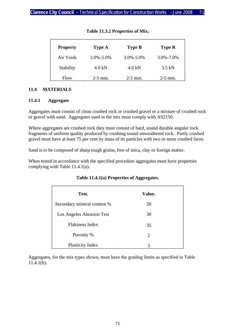
Clarence City Council – Technical Specification for Construction Works - June 2008 71
71
Table 11.3.2 Properties of Mix.
Property
Air Voids
Stability
Flow
Type A
3.0%-5.0%
4.0 kN
2-5 mm.
Type B
3.0%-5.0%
4.0 kN
2-5 mm.
Type R
3.0%-7.0%
3.5 kN
2-5 mm. 11.4 MATERIALS 11.4.1 Aggregate Aggregates must consist of clean crushed rock or crushed gravel or a mixture of crushed rock or gravel with sand. Aggregates used in the mix must comply with AS2150. Where aggregates are crushed rock they must consist of hard, sound durable angular rock fragments of uniform quality produced by crushing sound unweathered rock. Partly crushed gravel must have at least 75 per cent by mass of its particles with two or more crushed faces. Sand is to be composed of sharp tough grains, free of mica, clay or foreign matter. When tested in accordance with the specified procedure aggregates must have properties complying with Table 11.4.1(a).
Table 11.4.1(a) Properties of Aggregates.
Test.
Secondary mineral content %
Los Angeles Abrasion Test
Flakiness Index
Porosity %
Plasticity Index
Value.
20
30
35
2
3 Aggregates, for the mix types shown, must have the grading limits as specified in Table 11.4.1(b).

Clarence City Council – Technical Specification for Construction Works - June 2008 72
72
Table 11.4.1(b) Grading Limits for Mix.
% Passing AS Sieve.
13.2
9.5
6.7
4.75
2.36
1.18
0.600
0.300
0.150
0.075
Type A
100
95-100
80-95
65-80
45-60
35-50
25-40
15-25
7-15
3-10
Type B
100
90-100
65-85
60-80
55-75
45-65
30-50
20-30
10-18
0 5-11
Type R
100
100
100
85-100
55-80
38-60
25-43
15-30
0 8-20
0 8-20 11.4.2 Filler Where additional filler is required to be added to obtain the requirements of the above grading they must conform with AS 2357. 11.4.3 Binder The binder to be used in the mix is to be Class 170 Bitumen in accordance with AS 2008. The binder is to form the following percentage of the total mix for the mix types specified in Table 11.4.3.
Table 11.4.3 Proportion of Bitumen Binder in Mix
Binder content as Bitumen.
Percentage of mix.
Type A
6.0-7.0
Type B
5.8-6.8
Type R
6.5-7.5

Clarence City Council – Technical Specification for Construction Works - June 2008 73
73
11.4.4 Additives No additives are to be added to the mix without the approval of the Engineer. 11.4.5 Primer The primer is to consist of either a class AMC2 or AMC3 cutback bitumen to AS 2157 or a rapid setting bitumen emulsion conforming to AS 1160. 11.4.6 Tack Coat The tack coat is to consist of either a cutback bitumen to class AMC2 or AMC3 to AS 2157 or rapid setting bitumen emulsion conforming to AS 1160. 11.5 PREPARATION 11.5.1 Protection of Other Works Concrete kerbs and channel, access chamber and utility covers and such like are to be masked with paper or covered prior to carrying out surfacing works. Gratings must be firmly covered to prevent bitumen, aggregate or asphalt from entering the drain or pit. The location of utility or access chamber covers within the area to be surfaced are to be either raised or clearly marked and recorded prior to carrying out the surfacing and must be uncovered as soon as practicable after the completion of the work. 11.5.2 Surface Preparation The surface is to be swept to remove any loose stones, dust, dirt, or foreign material from the previously prepared base. Care is to be taken to avoid damage to the surface by sweeping. The pressure applied to the brooms is to be appropriate to the pavement material and type of bristle used. The surface must be dampened prior to sweeping as required. Sweeping is to extend to the edge of kerb and channels or 300mm beyond the line of the proposed surfacing in the case of shoulders. Any grass or weed growth encroaching on or through the surface to be paved must be sprayed with an approved herbicide and removed well in advance of paving. Any area affected by oil contamination is to be cleaned or removed and replaced with asphalt. 11.5.3 Priming All previously unsealed pavements are to be pre-treated using an approved primer coat. The application rate of the primer coat is to depend on the type and condition of the pavement material and the amount of dilution or cutting required. The application rate must generally be in accordance with Table 11.5.3.

Clarence City Council – Technical Specification for Construction Works - June 2008 74
74
Table 11.5.3 Application Rates For Primer Coats
Material
Bitumen emulsion
Bitumen emulsion
Cutback bitumen
Cutback bitumen
Class/ Grade
ARS
CRS
AMC2
AMC3
Application Rate (l/m2)
0.80 - 1.10
0.80 - 1.10
0.80 - 1.10
0.80 - 1.10
Spraying Temperature
(oC)
Ambient
Ambient
75 - 100
95 - 115
Sufficient time is to be allowed for the primer to cure or set. Curing time is to depend on traffic, percentage of cutter in the primer or the weather conditions but in no cases is a previously primed surface to be resurfaced within 48 hours of the priming being completed. 11.5.4 Regulating (Correction) Coarse Where the surface to be paved varies by more than 20mm from the bottom of a 3.0 metre long straight edge laid in any direction the Engineer may require a separate regulating (correction) coarse to be placed. Details of the proposed mix design to be used for the regulation (correction) coarse are to be submitted to the Superintendent for approval prior to commencing the works. 11.5.5 Tack Coat Where in the opinion of the Engineer a tack coat is required between a previously sealed or primed pavement surface the Contractor must apply an approved tack coat. The tack coat is to normally consist of cut-back bitumen in accordance with Clause 11.4.6. However where conditions dictate, a bitumen emulsion may be used subject to the approval of the Engineer. The application rate of the tack coat is to depend on the type and condition of the pavement material and the amount of dilution or cutting required. The application rate must generally be in accordance with Table 11.5.5.
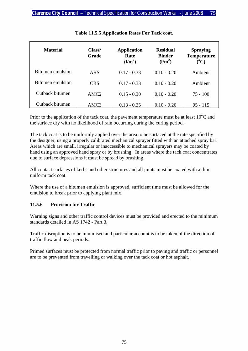
Clarence City Council – Technical Specification for Construction Works - June 2008 75
75
Table 11.5.5 Application Rates For Tack coat.
Material
Bitumen emulsion
Bitumen emulsion
Cutback bitumen
Cutback bitumen
Class/ Grade
ARS
CRS
AMC2
AMC3
Application Rate (l/m2)
0.17 - 0.33
0.17 - 0.33
0.15 - 0.30
0.13 - 0.25
Residual Binder (l/m2)
0.10 - 0.20
0.10 - 0.20
0.10 - 0.20
0.10 - 0.20
Spraying Temperature
(oC)
Ambient
Ambient
75 - 100
95 - 115 Prior to the application of the tack coat, the pavement temperature must be at least 10oC and the surface dry with no likelihood of rain occurring during the curing period. The tack coat is to be uniformly applied over the area to be surfaced at the rate specified by the designer, using a properly calibrated mechanical sprayer fitted with an attached spray bar. Areas which are small, irregular or inaccessible to mechanical sprayers may be coated by hand using an approved hand spray or by brushing. In areas where the tack coat concentrates due to surface depressions it must be spread by brushing. All contact surfaces of kerbs and other structures and all joints must be coated with a thin uniform tack coat. Where the use of a bitumen emulsion is approved, sufficient time must be allowed for the emulsion to break prior to applying plant mix. 11.5.6 Provision for Traffic Warning signs and other traffic control devices must be provided and erected to the minimum standards detailed in AS 1742 - Part 3. Traffic disruption is to be minimised and particular account is to be taken of the direction of traffic flow and peak periods. Primed surfaces must be protected from normal traffic prior to paving and traffic or personnel are to be prevented from travelling or walking over the tack coat or hot asphalt.

Clarence City Council – Technical Specification for Construction Works - June 2008 76
76
11.6 TRANSPORT 11.6.1 Transport and Delivery Asphalt must be delivered to the site without undue loss of temperature, separation of the mix or contamination with foreign matter. Delivery is to be uniform and the rate must be within the capacity of the spreading and compacting plant. Waiting time and delays at the site are to be avoided. No loads are to be delivered to the site so late in the day that they cannot be completely spread and compacted before sunset. All trucks used for delivering the mix must have clean, smooth metal tipping bodies with a minimum capacity of 6 tonnes and be in good mechanical condition. The trucks are to be fitted with suitable tailgates and chutes to permit controlled discharge without spillage. The interior of each truck body is to be cleaned of all foreign matter and lightly lubricated with an approved release agent, and any excess release agent removed, prior to loading. The loads are to be covered during transport with heavy duty covers to protect the load from the weather. The truck bodies and cover are to be insulated to the satisfaction of the Engineer if the delivery distance exceeds 50 km and the ambient temperature is below 15oC. 11.6.2 Temperature The temperature of the asphalt mix must be controlled to protect the mix and allow adequate spreading and compacting. The temperature of the mix, when delivered into the spreading plant, for a range of ambient shade temperatures measured at the road surface, is to be within the ranges specified in Table 11.6.2.
Table 11.6.2 Acceptable mix Temperature.
Material. Temperature. oC Asphalt on discharge from plant. Asphalt at spreading plant for Ambient Temp. of;
10 - 15oC 15 - 25oC above 25oC
Minimum. -
145 140 135
Maximum.
170
170 160 155
Clarence City Council – Technical Specification for Construction Works - June 2008 77
77
Where the layer thickness exceeds 40mm the above minimum temperatures of the mix may be reduced by up to 5oC and, if laid on a previously placed layer that has not cooled below 60oC, the above minimum temperatures of the mix may be reduced by up to 15oC. In no circumstances is the mix be laid when the ambient temperature is below 5oC. 11.6.3 Delivery Dockets Delivery dockets are to be provided with each load and a copy is to be made available to the Engineer or his representative. Each docket must state the following:
a) Loaded and unloaded mass of the truck; b) The registration number of the truck; c) Date and time of loading; d) The temperature of the mix at loading; e) The name of the supplier; and f) The mix type designation and plant location.
11.7 SPREADING 11.7.1 Organisation of the Work Unless otherwise approved by the Engineer, the work is to be organised to ensure that each days layer spread covers the full width of the carriageway. The asphalt is to be spread in such a manner as to minimise the number of longitudinal joints and traverse joints. Laying of the asphalt mix must not commence until sufficient asphalt is on site to allow continuous spreading operations. The speed of the spreading plant is to be matched to the rate of delivery to minimise delays. 11.7.2 Spreading The asphalt layer is to be spread and compacted to the specified line, level and minimum depth shown on the drawings or as directed. The spreading of the asphalt mix must generally be carried out using a self propelled paver. Laying of the asphalt must not proceed if the road is wet or rain is imminent, the temperature is less than that specified in Clause 11.6.2 of this specification or if cold winds cool the mix to the extent that spreading or compaction would be adversely effected. The asphalt must be spread without tearing, gouging or displacement of the aggregate to produce a smooth, even surface. Immediately after laying and before compacting commences the surface is to be checked and any unevenness corrected. All fatty, sandy, hungry or dusty areas must be removed and replaced with fresh hot asphalt. Irregularities in the edge are to be corrected by the removal or addition of fresh hot asphalt. Where asphalt is required to match an existing surface, road, bridge deck, fixed rail or other fixture, particular care is to be taken to achieve a smooth surface.

Clarence City Council – Technical Specification for Construction Works - June 2008 78
78
11.7.3 Hand Spreading Spreading of the asphalt mix by hand is not permitted except for inaccessible areas and footpaths. Where material is required to be laid by hand it must be placed without segregation and spread from the centre by lute or the back of a rake. No material is to be thrown or scattered and any segregated coarse particles are to be removed. All workman employed in hand work are to be experienced and competent in the spreading and correcting of asphalt. 11.8 JOINTS 11.8.1 Longitudinal Joints Longitudinal joints are to be located parallel to the centreline of the carriageway and must be displaced at least 150mm from a joint in a lower layer. 11.8.2 Traverse Joints Traverse joints are to be made wherever the spreading operation is stopped for thirty (30) minutes or more. Traverse joints must be at right angles to the direction of paving. The joints may be formed with a vertical face against a stop board or feathered out. The feathered material is to be cut out at least 25mm into sound, full depth asphalt prior to recommencing laying. Traverse joints must be separated by at least two (2) metres between successive layers and adjacent runs. 11.9 COMPACTING 11.9.1 General Compacting of the mix must commence as soon as the asphalt can support the compacting equipment without undue displacement. Delays in the commencement of compacting will not be permitted. The asphalt layer is to be compacted to a target density of 95% of the compacted density determined in accordance with Clause 11.3.2 of this specification. 11.9.2 Compaction Plant Rollers must be fitted with scrapers or bars and kept moist to avoid any pick-up of asphalt. The rollers are to be operated by experienced and competent drivers in a continuous operation to ensure that all parts of the pavement receive equal compacting. Rollers are not to remain stationary on recently compacted work.

Clarence City Council – Technical Specification for Construction Works - June 2008 79
79
11.9.3 Initial Compaction Material spread by paver is to be compacted initially using tandem steel wheel static or vibratory rollers of 6 - 10 tonnes. Vibratory rollers are to be fitted with a cut off to stop vibration when coming to a stop or changing direction and must have a maximum amplitude of vibration of 1.0mm and a frequency of between 30 - 50 Hz. Any traverse or longitudinal joints are to be rolled first and rolling is to then continue in longitudinal runs at a uniform speed of approximately 5 km/h, commencing from the lowest edge and continuing to the higher side of the spread asphalt. Adjoining runs are to be overlapped by at least 150mm and adjacent runs are to be of different lengths. The first pass , and second for Type B mix, of a vibrating roller is to be made using the static weight only and must be completed before the temperature of the mix at mid-depth has reached 105oC. 11.9.4 Intermediate Compaction Intermediate rolling is to be carried out to achieve the target compaction using tandem steel wheel vibratory rollers of 6 - 10 tonnes, or multi-wheel pneumatic tyred rollers of 10 - 12 tonne mass fitted with 7 - 11 wheels so placed to give overlapping tyre paths and complete coverage for the effective width of the roller and tyres capable of being inflated to 700 kPa. Rolling is to be carried out in a similar pattern to the initial passes at speeds no greater than 25 km/h and must be completed before the temperature of the mix at mid-depth has reached 80oC. 11.9.5 Final Compaction Final rolling is to be carried out as necessary to remove all roller marks, using static steel wheeled tandem rollers or multi-wheel pneumatic tyred rollers and must be completed before the temperature of the mix at mid-depth has reached 60oC. 11.9.6 Hand Compaction Asphalt requiring compacting by hand around manholes, where rollers cannot operate or in footpaths are to be compacted in layers of sufficient thickness to allow compacting to the specified density, and are to be finished with a texture similar to rolled asphalt.

Clarence City Council – Technical Specification for Construction Works - June 2008 80
80
11.10 ACCEPTANCE 11.10.1 Inspections The Engineer may arrange for inspection at the plant of production, loading and testing, and may endorse the delivery dockets. Such endorsement is not to be taken to indicate approval of the mix nor effect the right of the Engineer to latter reject asphalt not in conformity with this specification. Wherever such endorsement is undertaken by the Engineer or his representative, any asphalt arriving at the spreading site without such endorsement may be liable to rejection. At the discretion of the Engineer, testing of the mix or raw materials may be carried out at any time to ensure compliance with this specification and facilities must be provided to allow samples to be taken. The Engineer may inspect the laying of the asphalt and will reject any asphalt that has not the correct temperature, texture, depth, shape or level. 11.10.2 Tolerances Unless otherwise specifically permitted in writing by the Engineer, the tolerances on the asphalt mix and construction shall be as set out below and the Engineer may reject any material not complying with these standards.
a) Grading
The production tolerances on the job mix grading must be in accordance with the following table:
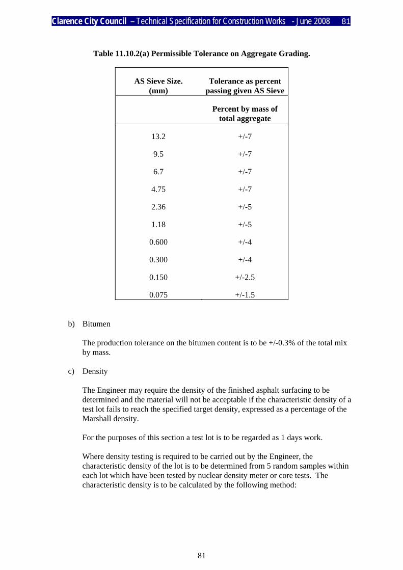
Clarence City Council – Technical Specification for Construction Works - June 2008 81
81
Table 11.10.2(a) Permissible Tolerance on Aggregate Grading.
AS Sieve Size. (mm)
Tolerance as percent passing given AS Sieve
Percent by mass of total aggregate
13.2
9.5
6.7
4.75
2.36
1.18
0.600
0.300
0.150
0.075
+/-7
+/-7
+/-7
+/-7
+/-5
+/-5
+/-4
+/-4
+/-2.5
+/-1.5
b) Bitumen
The production tolerance on the bitumen content is to be +/-0.3% of the total mix by mass.
c) Density
The Engineer may require the density of the finished asphalt surfacing to be determined and the material will not be acceptable if the characteristic density of a test lot fails to reach the specified target density, expressed as a percentage of the Marshall density. For the purposes of this section a test lot is to be regarded as 1 days work. Where density testing is required to be carried out by the Engineer, the characteristic density of the lot is to be determined from 5 random samples within each lot which have been tested by nuclear density meter or core tests. The characteristic density is to be calculated by the following method:

Clarence City Council – Technical Specification for Construction Works - June 2008 82
82
D = x - 1.53 * ( n - 1 ) where
x = mean of the sample densities. n - 1 = standard deviation of the lot expressed as a percentage of the
Marshall density.
d) Thickness The tolerance of the compacted layer thickness is to be +10/-0 millimetres.
e) Level The level of the finished surface is to have a tolerance of +/- 10 mm., except that where the asphalt is placed up against kerb and channel the level is to have a tolerance of +/- 5 mm. from the lip of the channel.
f) Surface The surface of the finished asphalt layer must not vary from the bottom of a 3.0 metre straight edge laid in any direction by more than the tolerances set out in Table 11.10.2(b).
Table 11.10.2(b) Permissible Tolerance on Shape.
Location.
Minor roads and residential streets
Parking areas, driveways handwork.
Deviation from Straight Edge
mm.
+/-7
+/-10

Clarence City Council – Technical Specification for Construction Works - June 2008 83
83
TECHNICAL SPECIFICATION FOR CONSTRUCTION WORKS
PART 12
SERVICE CONDUITS
I N D E X
CLAUSE TITLE 12.1 SCOPE OF WORK 12.2 STANDARDS 12.3 MATERIALS 12.3.1 BEDDING AND HAUNCHING 12.3.2 CONDUITS 12.4 LOCATION 12.5 INSTALLATION 12.5.1 EXCAVATION 12.5.2 CONDUITS 12.5.3 BEDDING AND HAUNCHING 12.5.4 BACKFILL 12.5.5 LOCATION INDICATORS 12.6 ACCEPTANCE
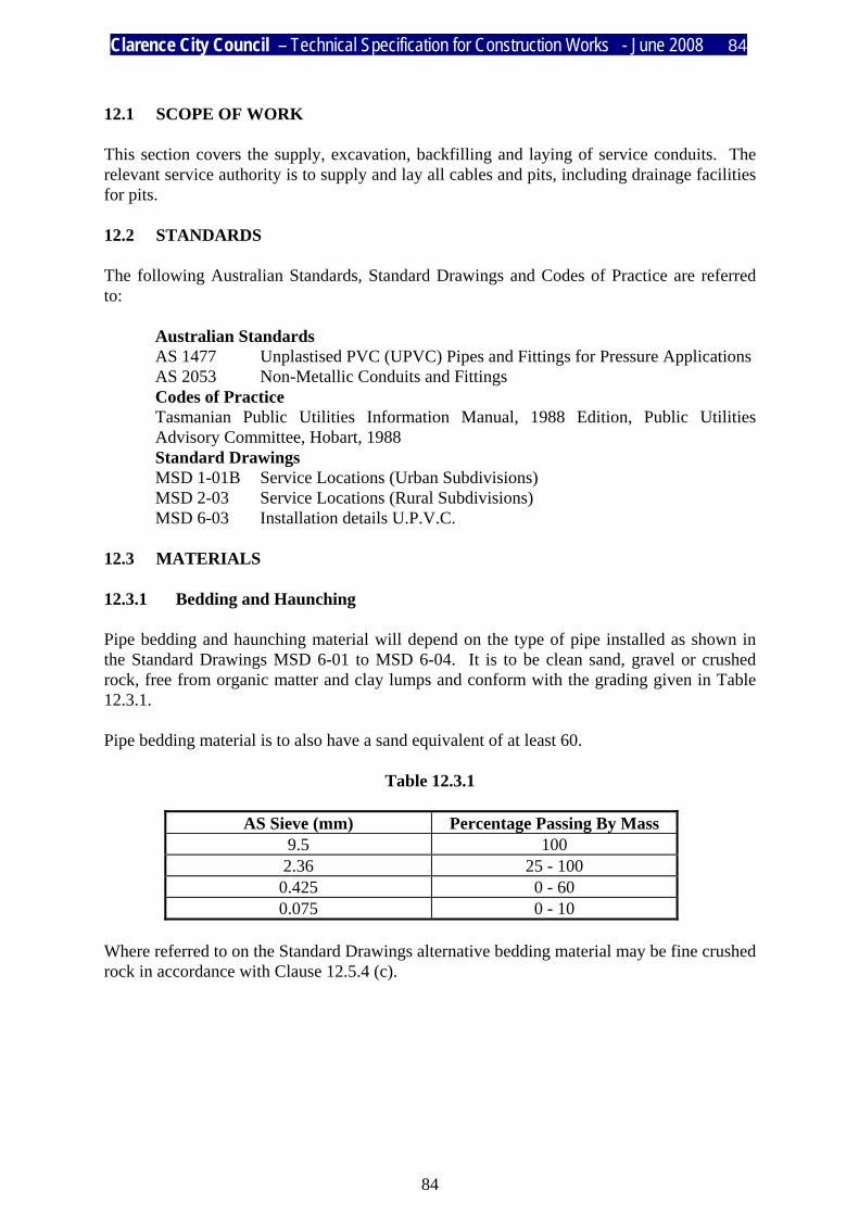
Clarence City Council – Technical Specification for Construction Works - June 2008 84
84
12.1 SCOPE OF WORK This section covers the supply, excavation, backfilling and laying of service conduits. The relevant service authority is to supply and lay all cables and pits, including drainage facilities for pits. 12.2 STANDARDS The following Australian Standards, Standard Drawings and Codes of Practice are referred to:
Australian Standards AS 1477 Unplastised PVC (UPVC) Pipes and Fittings for Pressure Applications AS 2053 Non-Metallic Conduits and Fittings Codes of Practice Tasmanian Public Utilities Information Manual, 1988 Edition, Public Utilities Advisory Committee, Hobart, 1988 Standard Drawings MSD 1-01B Service Locations (Urban Subdivisions) MSD 2-03 Service Locations (Rural Subdivisions) MSD 6-03 Installation details U.P.V.C.
12.3 MATERIALS 12.3.1 Bedding and Haunching Pipe bedding and haunching material will depend on the type of pipe installed as shown in the Standard Drawings MSD 6-01 to MSD 6-04. It is to be clean sand, gravel or crushed rock, free from organic matter and clay lumps and conform with the grading given in Table 12.3.1. Pipe bedding material is to also have a sand equivalent of at least 60.
Table 12.3.1
AS Sieve (mm) Percentage Passing By Mass 9.5 100 2.36 25 - 100 0.425 0 - 60 0.075 0 - 10
Where referred to on the Standard Drawings alternative bedding material may be fine crushed rock in accordance with Clause 12.5.4 (c).

Clarence City Council – Technical Specification for Construction Works - June 2008 85
85
12.3.2 Conduits Conduits supplied by the Contractor are to be UPVC pipe of a type, size and colour approved by the appropriate service authority. 12.4 LOCATION Services must be located as shown on the Drawings. Unless otherwise stated, common trenching is to be used in accordance with the requirements of the Engineer and relevant service authorities. Covers to services are to be as shown on the Standard Drawings or as otherwise required by the relevant service authority. 12.5 INSTALLATION 12.5.1 Excavation Trenches are to be excavated to the location and minimum dimensions shown on the Drawings. Excavation is to be in accordance with Clause 12.4. Prior to excavation the Contractor is to confirm the location of all services. Excavations in existing pavement areas are to be made by first saw cutting the pavement surfacing. 12.5.2 Conduits Conduits must be supplied and installed as shown on the Drawings. Where pipes are cut the ends shall be left neat and regular. Conduits must be fitted with 2mm diameter galvanised draw wire and the ends plugged to prevent the entry of backfill. 12.5.3 Bedding and Haunching Bedding and haunching is to be placed as shown in the Standard Drawings and firmly compacted to the satisfaction of the Engineer. Care must be taken to ensure that the conduit is fully and evenly supported by the bedding material. Fine crushed rock bedding is to be compacted to 95 per cent of Standard Compaction in accordance with AS 1289. Metallic detector tape is to be installed above the pipe haunching.

Clarence City Council – Technical Specification for Construction Works - June 2008 86
86
12.5.4 Backfill a) Outside pavement areas. Backfill free of rocks or stones larger than 50mm, clay lumps larger than 150mm,
organic material or other deleterious matter, is to be placed in uniform layers not exceeding 450mm compacted thickness and watered and compacted to a minimum of 95 per cent of Standard Compaction.
b) New pavement areas. Backfill to the formation level, comprising sub-base material in accordance with
Part 6 of this Specification, Material and Pavement Construction, is to be placed in uniform layers not exceeding 150mm compacted thickness, and watered and compacted to a minimum of 95 per cent of Standard Compaction.
c) Existing pavement areas. The pavement is to be backfilled and reinstated to the satisfaction of the Engineer
using wet-mixed base course material in accordance with Part 6 of this Specification, Material and Pavement Construction. Backfill is to be placed in uniform layers not exceeding 150mm compacted thickness, and compacted to a minimum of 98 per cent of Modified Compaction. Excavations in existing pavements are to be reinstated as soon as practicable and in all cases a minimum carriageway width of 4.0 metres is to be maintained. No excavation is permitted to remain open over night without the written approval of the Engineer, and must therefore, be safely secured and made safe by the Contractor overnight. Unless otherwise approved by the Engineer, resurfacing of the pavement is to be carried out by the Council at the Contractor's expense.
12.5.5 Location Indicators The location of roadway conduit crossings are to be marked on kerbs using symbols approved by the Engineer. Where there is no kerb, the conduit location is to be marked using indicator posts in accordance with the requirements of the Engineer. 12.6 ACCEPTANCE The Engineer must inspect and approve the installation of conduits prior to backfill.

Clarence City Council – Technical Specification for Construction Works - June 2008 87
87
TECHNICAL SPECIFICATION FOR CONSTRUCTION WORKS
PART 13
GUIDE POSTS AND GUARD FENCE
I N D E X
CLAUSE TITLE 13.1 SCOPE OF WORK 13.2 STANDARDS 13.3 MATERIALS 13.3.1 GUIDE POSTS 13.3.2 STEEL BEAM GUARD FENCE AND POST AND CABLE GUARD
FENCE 13.3.3 DELINEATORS 13.3.4 PAINT 13.4 GUIDE POSTS 13.4.1 SPACING 13.4.2 INSTALLATION 13.4.3 PAINTING 13.5 STEEL BEAM GUARD FENCE 13.5.1 HANDLING 13.5.2 INSTALLATION 13.6 POST AND CABLE GUARD FENCE 13.6.1 HANDLING 13.6.2 INSTALLATION 13.7 DELINEATORS 13.8 ACCEPTANCE
Clarence City Council – Technical Specification for Construction Works - June 2008 88
88
1. SCOPE OF WORK This specification covers the supply and delivery of all materials, labour and plant necessary for installation or removal of guide posts, steel beam guard fence, post and cable guard fence and delineators. 13.2 STANDARDS The following Australian Standards and Standard Drawings are referred to:
Australian Standards AS 1214 Hot-dipped Galvanised Coatings on Threaded Fasteners AS 1627.5 Pickling Steel Surfaces AS 1650 Hot-dipped Galvanised Coatings on Ferrous Articles AS 1742.3 Traffic Control Devices For Works on Roads AS 1906.2 Retroreflective Devices (Non-pavement Application) AS 2082 Visually Stress-Graded Hardwood for Structural Purposes AS 3569 Steel Wire Ropes Department of Transport and Standard Drawings 3402-4/P65-1 Post and Cable Guard MSD 2-04 Guide Posts and Delineators
13.3 MATERIALS 13.3.1 Guide Posts Posts are to be 100mm by 50mm nominal size and are to be cut from rough sawn green hardwood complying with Clause 2.4, Structural Grade 4, and Clause 2.7, Appearance Grades, of AS 2082, except that the requirements for bow, spring and twist shall be reduced by 75 per cent of the values given in Appendix B, Tables B1 and B2 of AS 2082. Steel guide posts may be used subject to the approval of the Engineer. 13.3.2 Steel Beam Guard Fence and Post and Cable Guard Fence Except where specified otherwise in the relevant Australian Standards, rails, posts, terminals and stiffening plates are to be manufactured from capped or semi-killed steel having an ultimate tensile strength of not less than 356 MPa and a thickness of not less than 2.5 mm. Bolts, nuts and washers are to be manufactured from Grade 250 steel. All rails, steel fittings and fasteners are to be hot dip galvanised to Type B in accordance with AS 1650 and AS 1627, Part 5. After galvanising the surface is to be chromate pacified in accordance with AS 1214. Surface finish is to be smooth to the touch and free from runs, blisters and irregularities.
Clarence City Council – Technical Specification for Construction Works - June 2008 89
89
13.3.3 Delineators Delineators are to be corner cube retro-reflectors in accordance with AS 1906, Part 2. 13.3.4 Paint Primer is to consist of approved oil based lead oxide wood primer. Finish coats are to be an approved flat white, free chalking paint in accordance with the Government Paint Committee approval scheme and complying with specification GPC-P-58. 13.4 GUIDE POSTS 13.4.1 Spacing Guide posts are to be installed on both sides of the carriageway at 150 metres maximum spacing, on curves in accordance with MSD 2-04, at either side of culverts and property access, or as otherwise directed by the Engineer. 13.4.2 Installation Posts are to be installed vertically to a depth of 500mm with the maximum dimension normal to the centre line of the carriageway. Driven posts are to be capped to avoid damage to the post. 13.4.3 Painting Posts are to be prepared and painted with one prime coat and two finish coats in accordance with the manufacturer's instructions. 13.5 STEEL BEAM GUARD FENCE 13.5.1 Handling Care must be taken during storage, handling and loading to avoid wet-storage staining and mechanical damage to the zinc coating. 13.5.2 Installation Steel beam guard fence must be installed as indicated on the drawings or as otherwise directed by the Engineer. Posts and block out pieces are to be erected vertically, with flanges parallel to the road centre line and with the open end of the channel section facing away from the approaching traffic. Posts are to be firmly fixed in the ground at the required centres.
Clarence City Council – Technical Specification for Construction Works - June 2008 90
90
Steel brackets suitable for fixing delineators are to be fixed to the posts at 150 metres maximum spacing and on curves in accordance with MSD 2-04. Rail sections are to be adjusted to form a smooth line and lapped so that exposed ends face away from the approaching traffic. 13.6 POST AND CABLE GUARD FENCE 13.6.1 Handling Care must be taken during storage, handling and loading to avoid wet-storage staining and mechanical damage to the zinc coating. 13.6.1 Installation Post and cable guard fence must be installed as indicated on the drawings or as otherwise directed by the Engineer. Posts must be erected vertically, with flanges parallel to the road centre line and with the open end of the channel section facing away from the approaching traffic. Posts are to be firmly fixed in the ground at the required centres. Steel brackets suitable for fixing delineators are to be fixed to the posts at 150 metres maximum spacing and on curves in accordance with MSD 2-04. Delineator plates are to be as shown on Department of Transport drawing 3402-4/P65-1. Steel cable is to be tensioned to the satisfaction of the Engineer so as to minimise cable sag but must not be tensioned to an extent whereby the supporting posts give visible indication of movement. Anchorage points are to be located to allow tensioning as specified above. 13.7 DELINEATORS Delineators are to be fixed to all guide posts and steel brackets attached to the steel beam guard fence and post and cable guard fence as in 13.5.2 and 13.6.2 above. One delineator is to be fixed to both faces of each post or bracket in accordance with Table 13.7.1.
Table 13.7.1 - Colour of Delineators
Road Type Colour Left Right
One way Two way
Red Red
Orange White
13.8 ACCEPTANCE The Engineer may inspect and approve the installation of all guide posts, steel beam guard fence, post and cable guard fence and delineators.