model construction specification
TRANSCRIPT
STEEL BUILDINGS IN EUROPE
Single-Storey Steel Buildings
Part 10: Model Construction
Specification


Single-Storey Steel Buildings
Part 10: Model Construction
Specification

10 - ii
Part 10: Model Construction Specification
10 - iii
FOREWORD
This publication is the tenth part of the design guide, Single-Storey Steel Buildings.
The 11 parts in the Single-Storey Steel Buildings guide are:
Part 1: Architect’s guide
Part 2: Concept design
Part 3: Actions
Part 4: Detailed design of portal frames
Part 5: Detailed design of trusses
Part 6: Detailed design of built up columns
Part 7: Fire engineering
Part 8: Building envelope
Part 9: Introduction to computer software
Part 10: Model construction specification
Part 11: Moment connections
Single-Storey Steel Buildings is one of two design guides. The second design guide is Multi-Storey Steel Buildings.
The two design guides have been produced in the framework of the European project “Facilitating the market development for sections in industrial halls and low rise buildings (SECHALO) RFS2-CT-2008-0030”.
The design guides have been prepared under the direction of Arcelor Mittal, Peiner Träger and Corus. The technical content has been prepared by CTICM and SCI, collaborating as the Steel Alliance.

Part 10: Model Construction Specification
10 - iv

Part 10: Model Construction Specification
10 - v
Contents Page No
FOREWORD iii
SUMMARY vii
1 INTRODUCTION 1 1.1 Scope 2
2 NORMATIVE REFERENCES 4
3 BASIS OF STRUCTURAL DESIGN 9 3.1 General assumptions according to EN 1990 9
4 ACTIONS ON STRUCTURES 10 4.1 Self-weight and imposed loads for buildings 10 4.2 Snow loads 10 4.3 Wind loads 11 4.4 Thermal actions 11 4.5 Actions during execution 11 4.6 Accidental actions 13 4.7 Actions induced by cranes 14 4.8 Seismic actions 15
5 DESIGN OF STEEL STRUCTURES 17 5.1 Rules for single-storey buildings – EN 1993-1-1 17 5.2 Supplementary rules for sheeting – EN 1993-1-3 18 5.3 Design of plated structural elements – EN 1993-1-5 18 5.4 Design of joints – EN 1993-1-8 18 5.5 Fatigue – EN 1993-1-9 19 5.6 Material toughness and through-thickness properties – EN 1993-1-10 19 5.7 Crane supporting structures – EN 1993-6 20
6 EXECUTION SPECIFICATION 21 6.1 General 21 6.2 Execution classes 21 6.3 Preparation grades 21 6.4 Geometrical tolerances 21
7 CONSTITUENT PRODUCTS 23 7.1 Identification, inspection documents and traceability 23 7.2 Structural steel products 23 7.3 Welding consumables 23 7.4 Mechanical fasteners 23 7.5 Grouting materials 24
8 PREPARATION AND ASSEMBLY 25 8.1 Identification 25 8.2 Handling and storage 25 8.3 Cutting 25 8.4 Shaping 25 8.5 Holing 25 8.6 Assembly 26
9 WELDING 27 9.1 General 27 9.2 Qualification of welding procedures 27

Part 10: Model Construction Specification
10 - vi
9.3 Welders and welding operators 27 9.4 Welding coordination 27 9.5 Preparation and execution of welding 27 9.6 Acceptance criteria 29
10 MECHANICAL FASTENING 30
11 ERECTION 31
12 CONSTRUCTOR’S DOCUMENTATION 34
13 INTERFACES OF THE STEEL STRUCTURE 35 13.1 Interface to concrete surfaces 35 13.2 Interface to neighbouring constructions 36
Appendix A MODEL PROJECT SPECIFICATION 37
Part 10: Model Construction Specification
10 - vii
SUMMARY
This guide is a Model Construction Specification to be used in contract documents for a typical construction project of a single-storey building. Its main objectives are to achieve greater uniformity in steelwork contract specifications in Europe and to provide a guide to specification of appropriate standards for the design, fabrication and erection of steelwork structures for buildings.
It deals with structural steelwork designed in accordance with applicable parts of the Eurocode Standards, to be executed in accordance with applicable parts of EN 1090. All the relevant Sections of the model specification are included in an appendix that can be directly copied and used in contracts, with any additional project-specific information that may be required.
Part 10: Model Construction Specification
10 - viii
Part 10: Model Construction Specification
10 - 1
1 INTRODUCTION
This guide is a Model Construction Specification to be used in contract documents for a typical construction project of a single-storey building. Its main objectives are:
To achieve greater uniformity in steelwork contract specifications in Europe.
To provide a guide to specification of appropriate standards for the design, fabrication and erection of steelwork structures for buildings.
It is essential that the designer and the steelwork contractor receive, on time, all information necessary for them to carry out the contract. This Model Construction Specification gives guidance on the items and information that should be included in the Project Specification.
The Member States of the EU and EFTA recognise that Eurocodes serve as reference documents for the following purposes:
As a means to prove compliance of building and civil engineering works with the essential requirements of Construction Products Directive 89/106/EEC of 21 December 1988 (amended by Directive 93/68/EEC of 22 July 1993), particularly Essential Requirement No. 1 – Mechanical resistance and stability – and Essential Requirement No. 2 – Safety in case of fire.
As a basis for specifying contracts for construction works and related engineering services.
As a framework for drawing up harmonised technical specifications for construction products (ENs and ETAs).
The Eurocodes, as far as they concern the construction works themselves, have a direct relationship with the Interpretative Documents referred to in Article 12 of the Construction Products Directive, although they are of a different nature from harmonised product standards. There is a need for consistency between the harmonised technical specifications for construction products and the technical rules for works.
The steel construction industry in Europe will have to use CE marked products. The performances of these products can be declared by reference to requirements given in:
The harmonised European Standards such as the standards EN 10025 and EN 1090. Parts 1 of these Standards (i.e. EN 10025-1 and EN 1090-1 respectively) include a special Annex ZA relating to CE marking.
A European Technical Approval (ETA).
CE Marking of steel products to EN 10025 has been mandatory since 2006. The use of CE marked products according to EN 1090 will be mandatory from the first semester 2011 for most of the European countries. Once it appears in the European Official Journal, the standard will be in the application phase.
Part 10: Model Construction Specification
10 - 2
In EN 1090-1, for some special types of construction products (modular construction for example), reference is made to the Eurocodes. In this case, it shall be mentioned which Nationally Determined Parameters have been taken into account.
Much of the information noted in this Model Construction Specification is based upon that given in these Standards, but it must not be inferred that the full details of the standards are not relevant.
References to applicable parts of European Standards have been made throughout this Model Construction Specification.
1.1 Scope This Model Construction Specification deals with structural steelwork designed in accordance with applicable parts of the Eurocode Standards and executed in accordance with applicable parts of EN 1090.
It can be used for all types of single- storey building construction designed for static loading, including cases where the dynamic effects are assessed using equivalent quasi-static loads and dynamic amplification factors, including wind actions and actions induced by hoists and cranes and cranes on runway beams.
It is not intended to be used for steelwork in dynamically loaded structures.
This Model Construction Specification covers structural steelwork produced from hot rolled structural steel products only. It does not cover structural steelwork produced from cold formed structural steel (only cold formed profiled steel sheeting and cold formed stressed-skin sheeting used as a structural diaphragm are herein covered), structural hollow sections, channels and tubes, and stainless steel products.
This Model Construction Specification should be introduced into a steelwork contract by a Project Specification, the contents of which are detailed in Appendix A of this document and completed with project-specific information. The Project Specification should also include any additions or modifications that may be required by the National Structural Steelwork Specification by the Client for a particular contract if the form of behaviour or other aspects of the structure are unorthodox.
Contract documents (which include architectural and/or structural design drawings, specifications and addenda) vary considerably in intricacy and completeness. Nonetheless, the designer, the fabricator and the erector must be able to rely upon the accuracy of the contract documents, in order to allow them to provide the Client with bids that are adequate and complete. It also enables the preparation of the general arrangement drawings and the shop and erection drawings, the ordering of materials and the timely fabrication and erection of construction components.
Critical requirements that are necessary to protect the Client’s interest, that affect the integrity of the structure or that are necessary for the designer, the

Part 10: Model Construction Specification
10 - 3
fabricator and the erector to proceed with their work, must be included in the contract documents. Non-exhaustive examples of critical information include:
Standard specifications and codes that govern structural steel design and construction, including bolting and welding
Material specifications
Welded-joint configuration and weld-procedure qualification
Surface preparation and shop painting requirements
Shop and field inspection requirements
If any, non-destructive testing (NDT) requirements, including acceptance criteria
Special requirements on delivery and special erection limitations.

Part 10: Model Construction Specification
10 - 4
2 NORMATIVE REFERENCES
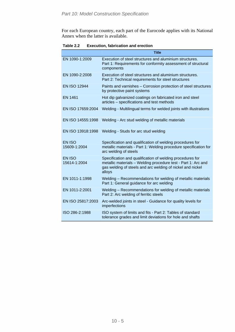
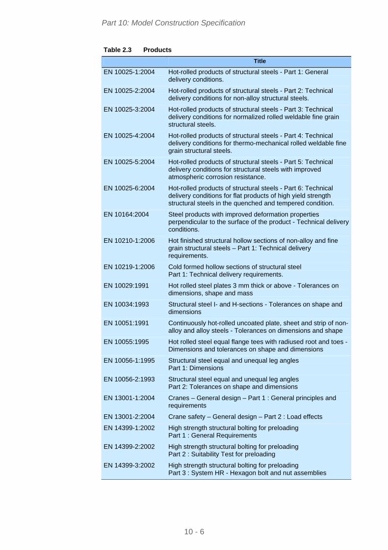
The European Standards incorporate, by dated or undated reference, provisions from other publications. These normative references are cited at the appropriate places in the text and the publications are listed in Tables 2.1 to 2.3.
Table 2.1 Design and structural engineering
Title
EN 1990:2002 Basis of structural design
EN 1991-1-1:2003 Actions on structures – Part 1-1: General actions – Densities, self- weight, imposed loads for buildings
EN 1991-1-2:2002 Actions on structures – Part 1-2: General actions – Actions on structures exposed to fire
EN 1991-1-3:2003 Actions on structures – Part 1-3: General actions – Snow loads
EN 1991-1-4:2005 Actions on structures – Part 1-4: General actions – Wind loads
EN 1991-1-5:2003 Actions on structures – Part 1-5: General actions – Thermal actions
EN 1991-1-6:2005 Actions on structures – Part 1-6: General actions – Actions during execution
EN 1991-1-7:2006 Actions on structures – Part 1-7: General actions – Accidental actions
EN 1991-3:2006 Actions on structures – Part 3 : Actions induced by cranes and machinery
EN 1993-1-1:2005 Design of steel structures – Part 1-1: General rules and rules for buildings
EN 1993-1-2:2005 Design of steel structures – Part 1-2: General rules – Structural fire design
EN 1993-1-3:2006 Design of steel structures – Part 1-3: General rules – Supplementary rules for cold-formed members and sheeting
EN 1993-1-4:2006 Design of steel structures – Part 1-4: General rules – Supplementary rules for stainless steels
EN 1993-1-5:2005 Design of steel structures – Part 1-5: Plated structural elements
EN 1993-1-8:2005 Design of steel structures – Part 1-8: Design of joints
EN 1993-1-9:2005 Design of steel structures – Part 1-9: Fatigue
EN 1993-1-10:2005 Design of steel structures – Part 1-10: Material toughness and through-thickness properties
EN 1993-6:2007 Design of steel structures – Part 6: Crane supporting structures
EN 1998-1:2004 Design of structures for earthquake resistance – Part 1: General rules, seismic actions and rules for buildings
Part 10: Model Construction Specification
10 - 5
For each European country, each part of the Eurocode applies with its National Annex when the latter is available.
Table 2.2 Execution, fabrication and erection
Title
EN 1090-1:2009 Execution of steel structures and aluminium structures. Part 1: Requirements for conformity assessment of structural components
EN 1090-2:2008 Execution of steel structures and aluminium structures. Part 2: Technical requirements for steel structures
EN ISO 12944 Paints and varnishes – Corrosion protection of steel structures by protective paint systems
EN 1461 Hot dip galvanized coatings on fabricated iron and steel articles – specifications and test methods
EN ISO 17659:2004 Welding - Multilingual terms for welded joints with illustrations
EN ISO 14555:1998 Welding - Arc stud welding of metallic materials
EN ISO 13918:1998 Welding - Studs for arc stud welding
EN ISO 15609-1:2004
Specification and qualification of welding procedures for metallic materials - Part 1: Welding procedure specification for arc welding of steels
EN ISO 15614-1:2004
Specification and qualification of welding procedures for metallic materials – Welding procedure test - Part 1: Arc and gas welding of steels and arc welding of nickel and nickel alloys
EN 1011-1:1998 Welding – Recommendations for welding of metallic materials Part 1: General guidance for arc welding
EN 1011-2:2001 Welding – Recommendations for welding of metallic materials Part 2: Arc welding of ferritic steels
EN ISO 25817:2003 Arc-welded joints in steel - Guidance for quality levels for imperfections
ISO 286-2:1988 ISO system of limits and fits - Part 2: Tables of standard tolerance grades and limit deviations for hole and shafts
Part 10: Model Construction Specification
10 - 6
Table 2.3 Products
Title
EN 10025-1:2004 Hot-rolled products of structural steels - Part 1: General delivery conditions.
EN 10025-2:2004 Hot-rolled products of structural steels - Part 2: Technical delivery conditions for non-alloy structural steels.
EN 10025-3:2004 Hot-rolled products of structural steels - Part 3: Technical delivery conditions for normalized rolled weldable fine grain structural steels.
EN 10025-4:2004 Hot-rolled products of structural steels - Part 4: Technical delivery conditions for thermo-mechanical rolled weldable fine grain structural steels.
EN 10025-5:2004 Hot-rolled products of structural steels - Part 5: Technical delivery conditions for structural steels with improved atmospheric corrosion resistance.
EN 10025-6:2004 Hot-rolled products of structural steels - Part 6: Technical delivery conditions for flat products of high yield strength structural steels in the quenched and tempered condition.
EN 10164:2004 Steel products with improved deformation properties perpendicular to the surface of the product - Technical delivery conditions.
EN 10210-1:2006 Hot finished structural hollow sections of non-alloy and fine grain structural steels – Part 1: Technical delivery requirements.
EN 10219-1:2006 Cold formed hollow sections of structural steel Part 1: Technical delivery requirements.
EN 10029:1991 Hot rolled steel plates 3 mm thick or above - Tolerances on dimensions, shape and mass
EN 10034:1993 Structural steel I- and H-sections - Tolerances on shape and dimensions
EN 10051:1991 Continuously hot-rolled uncoated plate, sheet and strip of non-alloy and alloy steels - Tolerances on dimensions and shape
EN 10055:1995 Hot rolled steel equal flange tees with radiused root and toes - Dimensions and tolerances on shape and dimensions
EN 10056-1:1995 Structural steel equal and unequal leg angles Part 1: Dimensions
EN 10056-2:1993 Structural steel equal and unequal leg angles Part 2: Tolerances on shape and dimensions
EN 13001-1:2004 Cranes – General design – Part 1 : General principles and requirements
EN 13001-2:2004 Crane safety – General design – Part 2 : Load effects
EN 14399-1:2002 High strength structural bolting for preloading Part 1 : General Requirements
EN 14399-2:2002 High strength structural bolting for preloading Part 2 : Suitability Test for preloading
EN 14399-3:2002 High strength structural bolting for preloading Part 3 : System HR - Hexagon bolt and nut assemblies

Part 10: Model Construction Specification
10 - 7
Table 2.3 Continued…
Title
EN 14399-4:2002 High strength structural bolting for preloading Part 4 : System HV - Hexagon bolt and nut assemblies
EN 14399-5:2002 High strength structural bolting for preloading Part 5 : Plain washers for system HR
EN 14399-6:2002 High strength structural bolting for preloading Part 6 : Plain chamfered washers for systems HR and HV
EN ISO 898-1:1999 Mechanical properties of fasteners made of carbon steel and alloy steel - Part 1: Bolts, screws and studs (ISO 898-1:1999)
EN 20898-2:1993 Mechanical properties of fasteners Part 2: Nuts with special proof load values - Coarse thread (ISO 898-2:1992)
EN ISO 2320:1997 Prevailing torque type steel hexagon nuts - Mechanical and performance requirements (ISO 2320:1997)
EN ISO 4014:2000 Hexagon head bolts - Product grades A and B (ISO 4014:1999)
EN ISO 4016:2000 Hexagon head bolts - Product grade C (ISO 4016:1999)
EN ISO 4017:2000 Hexagon head screws - Product grades A and B (ISO 4017:1999)
EN ISO 4018:2000 Hexagon head screws - Product grade C (ISO 4018:1999)
EN ISO 4032:2000 Hexagon nuts, style 1 - Product grades A and B (ISO 4032:1999)
EN ISO 4033:2000 Hexagon nuts, style 2 - Product grades A and B (ISO 4033:1999)
EN ISO 4034:2000 Hexagon nuts - Product grade C (ISO 4034:1999)
EN ISO 7040:1997 Prevailing torque hexagon nuts (with non-metallic insert), style 1 - Property classes 5, 8 and 10
EN ISO 7042:1997 Prevailing torque all-metal hexagon nuts, style 2 - Property classes 5, 8, 10 and 12
EN ISO 7719:1997 Prevailing torque type all-metal hexagon nuts, style 1 - Property classes 5, 8 and 10
ISO 1891:1979 Bolts, screws, nuts and accessories - Terminology and nomenclature – Trilingual edition
EN ISO 7089:2000 Plain washers- Nominal series- Product grade A
EN ISO 7090:2000 Plain washers, chamfered - Normal series - Product grade A
EN ISO 7091:2000 Plain washers - Normal series - Product grade C
EN ISO 10511:1997 Prevailing torque type hexagon thin nuts (with non-metallic insert)
EN ISO 10512:1997 Prevailing torque type hexagon nuts thin nuts, style 1, with metric fine pitch thread - Property classes 6, 8 and 10
EN ISO 10513:1997 Prevailing torque type all-metal hexagon nuts, style 2, with metric fine pitch thread - Property classes 8, 10 and 12
When manufactured construction products, with Harmonised Standards (i.e. EN 10025, EN 1090), are to be used, CE marking shall be placed on the products according to the relevant European Harmonised Standards. Harmonised Standards are European Standards adopted by the European
Part 10: Model Construction Specification
10 - 8
Committee for Standardisation (CEN), following a mandate issued by the European Commission (mandate M/120 for structural metallic products). Not all European Standards (ENs) are harmonised - only those which have been listed in the Official Journal.
When manufactured construction products, without Harmonized Standards, are to be used (i.e. metal anchors, fire protective products, metal frame building kits, fire stopping and fire sealing products, prefabricated building units, etc.), European Technical Approval Guidelines (ETAG) require manufacturers to place CE marking on their products in accordance with the relevant European Technical Approval (ETA).
The relevant ETAs shall be specified in the contract documents.
An full list of valid ETAs is available on the official website of the European Organisation for Technical Approvals (EOTA): www.eota.be.
The latest edition of the publication referred to applies.
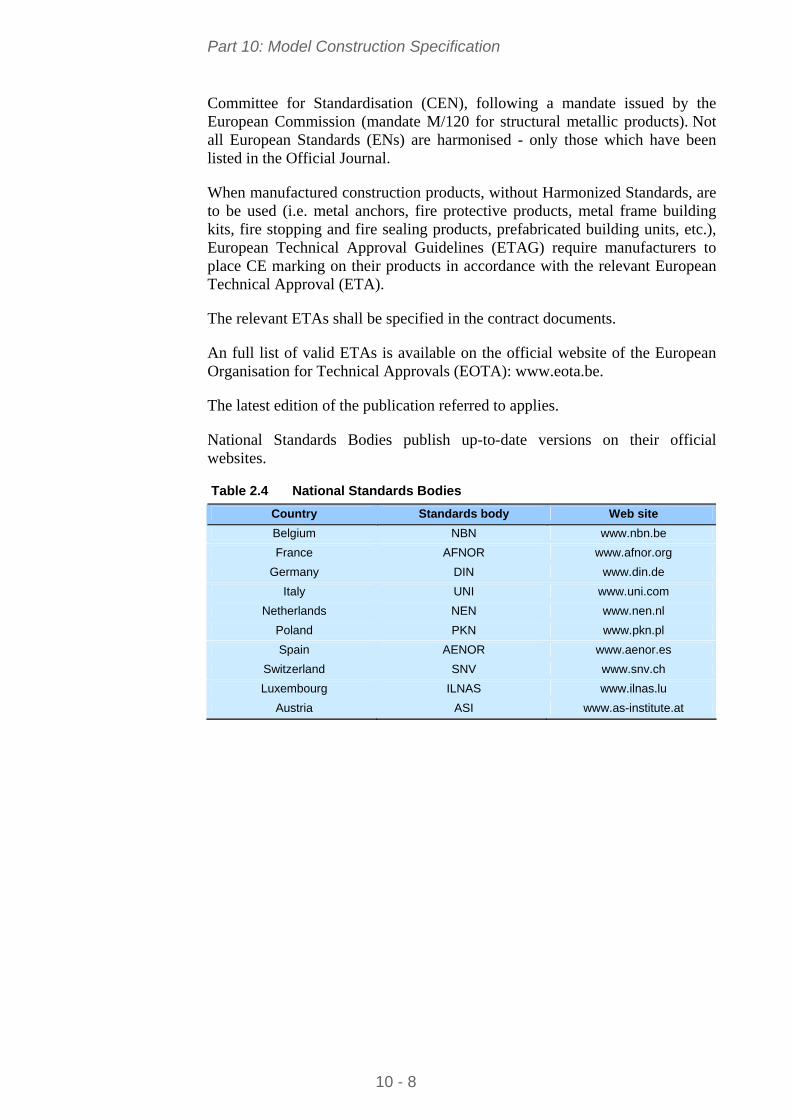
National Standards Bodies publish up-to-date versions on their official websites.
Table 2.4 National Standards Bodies
Country Standards body Web site
Belgium NBN www.nbn.be
France AFNOR www.afnor.org
Germany DIN www.din.de
Italy UNI www.uni.com
Netherlands NEN www.nen.nl
Poland PKN www.pkn.pl
Spain AENOR www.aenor.es
Switzerland SNV www.snv.ch
Luxembourg ILNAS www.ilnas.lu
Austria ASI www.as-institute.at
Part 10: Model Construction Specification
10 - 9
3 BASIS OF STRUCTURAL DESIGN
EN 1990 establishes the Principles and Requirements for safety, serviceability and durability of structures, describes the basis for their design and verification and gives guidelines for related aspects of structural reliability.
For the design of new structures, EN 1990 is intended to be used, for direct application, together with Eurocodes EN 1991 to 1999.
EN 1990 is applicable for the structural appraisal of existing construction, in developing the design of repairs and alterations or in assessing changes of use.
Design of steel structures shall conform to the basic requirements of § 2.1 of EN 1990.
Reliability, durability and quality management shall conform to § 2.2, § 2.4 and § 2.5 of EN 1990.
National choice is allowed through clauses listed in the Foreword to EN 1990.
3.1 General assumptions according to EN 1990 The choice of structural system and the design of the structure is made by
appropriately qualified and experienced personnel
Execution is carried out by personnel having the appropriate skill and experience
Adequate supervision and quality control is provided during the execution of the work, i.e. in design offices, factories, plants and on site
The construction materials and products are used as specified in EN 1990 or in the relevant execution standards or reference material or product specifications
The structure will be adequately maintained
The structure will be used in accordance with the design assumptions.
Additional contract document requirements
According to § 2.1(4)P of EN 1990, relevant additional specific events (impact, explosion, etc.), defined by the Client and the relevant authority, must be taken into account in the design and the execution of a structure.
According to § 2.3 of EN 1990, the contract documents should specify the design working life of the structure.
According to § 3.3(2) of EN 1990, the contract documents should state any relevant additional specific circumstances where the limit states that concern the protection of the contents are to classified as ultimate limit states.
According to § 3.4(1) of EN 1990, the contract documents shall specify the serviceability requirements of the project.
Part 10: Model Construction Specification
10 - 10
4 ACTIONS ON STRUCTURES
4.1 Self-weight and imposed loads for buildings EN 1991-1-1 gives design guidance and actions for the structural design of buildings, including the following aspects:
Densities of construction materials and stored materials
Self-weight of construction elements
Imposed loads for buildings.
National choice is allowed through clauses listed in the Foreword to EN 1991-1-1.
Additional contract document requirements
According to § 3.3.2(4) of EN 1991-1-1, the contract documents shall specify the imposed loads to be considered for serviceability limit state verifications, in accordance with the service conditions and the requirements concerning the performance of the structure.
According to § 4.1(1) and 4.1(2) of EN 1991-1-1, characteristic values of densities of construction and stored materials shall be specified in the contract documents, especially for materials which are not covered by the Tables in Appendix A.
According to § 6.1(4) of EN 1991-1-1, loads for heavy equipment (e.g. in communal kitchens, radiology rooms, boiler rooms, etc.) shall be agreed between the Client and the relevant authority and specified in the contract documents.
4.2 Snow loads EN 1991-1-3 gives guidance to determine the values of loads due to snow, to be used for the structural design of buildings.
National choice is allowed through clauses listed in the Foreword to EN 1991-1-3.
Additional contract document requirements
According to § 1.5 of EN 1991-1-3, in some circumstances tests and proven and/or properly validated numerical methods may be used to obtain snow loads on the construction works. These circumstances are those agreed with the Client and the relevant authority, and specified in the contract documents.
According to § 4.1(1) of EN 1991-1-3, to cover unusual local conditions, the National Annex may additionally allow the Client and the relevant authority to agree upon different characteristic values of snow load which have to be specified in the contract documents.
Part 10: Model Construction Specification
10 - 11
4.3 Wind loads EN 1991-1-4 gives guidance on the determination of natural wind actions for the structural design of buildings (with heights up to 200 m) for each of the loaded areas under consideration.
National choice is allowed through clauses listed in the Foreword to EN 1991-1-4.
Additional contract document requirements
According to § 7.2.2 of EN 1991-1-4, the rules for the velocity pressure distribution for leeward wall and sidewalls may be given in the National Annex or be defined for the individual project and specified in the contract documents.
4.4 Thermal actions EN 1991-1-5 gives design guidance, principles and rules for calculating thermal actions arising from climatic and operational conditions for the structural design of buildings. Principles needed for cladding and other appendages of buildings are also provided.
EN 1991-1-5 describes the changes in the temperature of structural elements. Characteristic values of thermal actions are presented for use in the design of structures which are exposed to daily and seasonal climatic changes. For structures not exposed to climatic conditions, thermal actions may not need to be considered.
National choice is allowed through clauses listed in the foreword to EN 1991-1-5.
Additional contract document requirements
According to § 5.2(2)P of EN 1991-1-5, operational effects (due to heating, technological or industrial processes) shall be considered in accordance with the particular project, and thus specified in the contract documents.
According to § 5.2(3)P of EN 1991-1-5, values of TM and Tp may be provided for the particular project, and thus specified in the contract documents.
4.5 Actions during execution EN 1991-1-6 gives principles and general rules for the determination of actions to be taken into account during the execution of buildings. EN 1991-1-6 can be used as guidance for the determination of actions to be taken into account during structural alterations, reconstruction, partial or full demolition, and for the determination of actions to be used for the design of auxiliary construction works (false-work, scaffolding, propping system, etc.) needed for the execution phases. Rules and additional information are given in Annexes A1 and B, and can also be defined in the National Annex or in the contract documents for the individual project.

Part 10: Model Construction Specification
10 - 12
National choice is allowed through clauses listed in the foreword to EN 1991-1-6.
Additional contract document requirements
The rules concerning the safety of persons, on and around the construction site, shall be specified in the contract documents for the individual project, and are outside the scope of EN 1991-1-6.
EN 1991-1-6 also provides rules for determining the actions that can be used for the calculation of auxiliary construction works needed for the execution phases.
The contract documents shall classify construction loads in accordance with Tables 2.2 and 4.1 of EN 1991-1-6.
Loads due to construction equipments, cranes and/or auxiliary structures can be classified as fixed or free loads, depending on their possible spatial variation; contract documents shall specify the loads and their classification.
If construction loads are classified as fixed, then the contract documents shall define tolerances for the possible deviations to the theoretical position.
If construction loads are classified as free, then the contract documents shall define the limits of the potential area of spatial variation.
In the absence of any specific requirement in the National Annex, the contract documents shall specify:
Return periods for the assessment of the characteristic values of variable (climatic, seismic, etc.) actions during execution phases (see § 3.1(5) of EN 1991-1-6)
A minimum wind velocity during execution phases (see § 3.1(5) of EN 1991-1-6)
Rules of combination of snow loads and wind action with the construction loads (see § 3.1(7) of EN 1991-1-6)
Geometric imperfections of the structure and the structural elements, for the selected design situations during execution (see § 3.1(8) of EN 1991-1-6)
Criteria associated with serviceability limit states during execution (see § 3.3(2) of EN 1991-1-6)
When appropriate, frequent values of particular loads to be taken into account (see § 3.3(5) of EN 1991-1-6)
Requirements of suitability for service of auxiliary structures in order to avoid excessive deformation and/or deflection that affect the durability, fitness for use or aesthetic appearance in the final stage (see § 3.3(6) of EN 1991-1-6).
Concerning the wind actions, the contract documents shall specify whether or not a procedure is needed for calculating dynamic response of the structure during the various stages of execution, taking into account the degree of

Part 10: Model Construction Specification
10 - 13
completion and stability of the structure and its components (see § 4.7(1) of EN 1991-1-6).
The contract documents shall specify the maximum allowable wind velocity during crane operations or other short term execution stages (see § 4.7(1) of EN 1991-1-6).
The contract documents shall specify, when relevant, accidental design situations due to cranes or exceptional conditions applicable to the structure or its exposure, such as impact, local failure and subsequent progressive collapse, fall of structural or non-structural parts, and abnormal concentrations of building equipment and/or building materials, water accumulation on steel roofs, fire, etc. (see § 4.12(1) and (3) of EN 1991-1-6).
The contract documents shall specify, when relevant, the design values of the ground acceleration as well as the importance factor I to be taken into account for the assessment of seismic actions, given the reference period of the considered transient situation (see § 4.13 of EN 1991-1-6).
The contract documents shall specify the characteristic values of horizontal actions due to imperfections or deformations related to horizontal displacements to be taken into account during execution phases (see § A1.3(1) of EN 1991-1-6).
4.6 Accidental actions EN 1991-1-7 describes Principles and Application rules for the assessment of accidental actions on buildings and bridges. The following actions are included:
Impact forces from vehicles, rail traffic, ships and helicopters
Actions due to internal explosions
Actions due to local failure from an unspecified cause.
EN 1991-1-7 does not specifically deal with accidental actions caused by external explosions, warfare and terrorist activities, or the residual stability of buildings damaged by seismic action or fire.
National choice is allowed through clauses listed in the Foreword to EN 1991-1-7.
Additional contract document requirements
According to § 2(2)P of EN 1991-1-7, the contract documents may specify the treatment of accidental actions which are not classified as free actions.
According to § 3.1(2) of EN 1991-1-7, the contract documents shall specify the strategies and rules to be considered for accidental design situations.
According to § 3.1(2) of EN 1991-1-7, notional values for identified accidental actions may be specified in the contract documents.
Part 10: Model Construction Specification
10 - 14
According to § 3.4(1) of EN 1991-1-7, the strategies for accidental design situations may be based on the Consequence Classes as set out in EN 1990. Thus, these Consequence Classes shall be specified in the contract documents.
According to § 4.3.1(2) of EN 1991-1-7, the contract documents shall specify whether or not the equivalent static design forces due to vehicular impact on members supporting structures over or adjacent to roadways, Fdx and Fdy, act simultaneously.
According to § 4.5.1.2 of EN 1991-1-7, if the building may be subject to impact from derailed railway traffic, the contract documents shall define whether it is a Class A or Class B structure.
According to § 4.5.2(1) of EN 1991-1-7, frontal and lateral dynamic design forces due to impact from river and canal traffic, as well as the height of application of the impact force and the impact area shall be specified in the contract documents.
4.7 Actions induced by cranes EN 1991-3 gives design guidance and specifies imposed loads (models and representative values) induced by hoists and cranes on runway beams, which include dynamic effects and braking, acceleration and accidental forces.
National choice is allowed through clauses listed in the Foreword to EN 1991-3.
Additional contract document requirements
Unless more accurate data (concerning the crane characteristics) is specified in the contract documents (the crane supplier shall therefore be known at the time of writing the contract documents), provisions of Section 2 of EN 1991-3 apply.
According to § 2.3(6) of EN 1991-3, the contract documents shall specify whether or not tests are performed with cranes on the supporting structures for the serviceability limit state verification.
According to § 2.5.2.2(2) of EN 1991-3, the contract documents shall specify whether one or several forces of the five horizontal types (a) to (e) listed in 2.5.2.2(1) shall be included in the same group of simultaneous crane load components.
According to § 2.5.2.2(4) of EN 1991-3, the contract documents shall specify the way the longitudinal horizontal forces HL,i and the transverse horizontal wheel forces HT,i, caused by acceleration and deceleration of masses of the crane or the crab, shall be applied. Otherwise, provisions given in Figure 2.3 of EN 1991-3 shall apply.
According to § 2.5.3(2) of EN 1991-3, the contract documents shall define the maximum number of cranes to be taken into account as acting simultaneously.

Part 10: Model Construction Specification
10 - 15
The Hoisting Class (HC1 to HC4) of the crane shall be specified in the contract documents, unless it is specified in the crane supplier specification. Reference can be made to Annex B (informative) of EN 1991-3.
According to § 2.9.1(1) of EN 1991-3, the contract documents shall specify the vertical load to be applied to access walkways, stairs and platform. Otherwise, provisions given in § 2.9.1(2), 2.9.1(3) or 2.9.1(4) shall apply.
According to § 2.9.2(1) of EN 1991-3, the contract documents shall specify the horizontal load to be applied to the guard rail. Otherwise, provisions given in § 2.9.2(1) or 2.9.2(2) shall apply.
To make allowance of relevant accidental actions, the contract documents shall specify:
Whether buffers are used or not
Whether or not a crane with horizontally restrained loads can tilt when its load or lifting attachment collides with an obstacle.
To make allowance for fatigue effects, the contract documents shall provide sufficient information on the operational conditions; the fatigue loads can then be determined according to EN 13001 and Annex A of EN 1993-1-9. Otherwise, provisions of § 2.12 of EN 1991-3 apply.
Where a simplified approach for determining the fatigue loads is favoured in the contract documents, the latter shall specify:
the class of load spectrum (Q0 to Q5) for all tasks of the crane
the class of total number of working cycles (U0 to U9) during the design life of the crane
the crane classification (S0 to S9). If the crane classification is not included in the crane supplier specification, reference can be made to Annex B (informative) of EN 1991-3.
According to § A.3.2(1) of the normative Annex A of EN 1991-3, the contract documents shall specify the partial factor for actions on crane supporting structures to be used in serviceability limit states. Otherwise, this partial factor shall be taken as 1,0.
4.8 Seismic actions EN 1998-1 applies to the design and construction of buildings and civil engineering works in seismic regions. Its purpose is to ensure that in the event of earthquakes:
Human lives are protected
Damage is limited
Structures important for civil protection remain operational (special structures such as nuclear power plants, offshore structures and large dams, are beyond the scope of EN 1998-1).
Part 10: Model Construction Specification
10 - 16
One fundamental issue in EN 1998-1 is the definition of the seismic action. Given the wide difference of seismic hazard and seismo-genetic characteristics in the various member countries, the seismic action is herein defined in general terms. The definition allows various Nationally Determined Parameters which shall be confirmed or modified in the National Annexes.
National choice is allowed through clauses listed in the Foreword to EN 1998-1.
Additional contract document requirements
According to § 2.1(2) and (3) of EN 1998-1, target reliabilities for the no-collapse requirement and for the damage limitation requirement are established by the National Authorities for different types of buildings on the basis of the consequences of failure. Contract documents shall specify the Importance Class of the individual project (see 4.2.5 of EN 1998-1).
Depending on the Importance Class of the structure and the particular conditions of the project, contract documents shall specify whether or not ground investigations and/or geological studies shall be performed to identify the ground type (A, B, C, D, E, S1 or S2), according to Table 3.1 of EN 1998-1.
Contract documents shall specify the seismic zone of the individual project (according to the zonation map, decided by the National Authority, and found in the National Annex to EN 1998-1).
Contract documents shall specify according to which concept earthquake resistant steel buildings shall be designed to (DCL, DCM or DCH).
According to 6.2(8) of EN 1998-1, the required toughness of steel and welds and the lowest service temperature adopted in combination with the seismic action shall be defined in the contract documents.

Part 10: Model Construction Specification
10 - 17
5 DESIGN OF STEEL STRUCTURES
Eurocode 3 is intended to be used in conjunction with:
EN 1990 Basis of structural design
EN 1991 Actions on structures
ENs, ETAGs and ETAs for construction products relevant for steel structures
EN 1090 Execution of Steel Structures – Technical requirements
EN 1992 to EN 1999 when steel structures or steel components are referred to.
Eurocode 3 is concerned only with requirements for resistance, serviceability, durability and fire resistance of steel structures. Other requirements, e.g. concerning thermal or sound insulation, are not covered.
5.1 Rules for single-storey buildings – EN 1993-1-1 EN 1993-1-1 gives basic design rules for steel structures with material thicknesses t > 3 mm. It also gives supplementary provisions for the structural design of single-storey steel buildings.
Material properties for steels and other construction products and the geometrical data to be used for design shall be those specified in the relevant ENs, ETAGs or ETAs unless otherwise indicated.
National choice is allowed through clauses listed in the Foreword to EN 1993-1-1.
Additional contract document requirements
The design working life shall be taken as the period for which a building structure is expected to be used for its intended purpose. For the specification of the intended design working life of a permanent building see Table 2.1 of EN 1990.
The effects of deterioration of material, corrosion or fatigue where relevant shall be taken into account by appropriate choice of material, see EN 1993-1-4 and EN 1993-1-10, and details, see EN 1993-1-9, or by structural redundancy and by the choice of an appropriate corrosion protection system.
The dimensional and mass tolerances of rolled steel sections and plates shall comply with the relevant product standard, ETAG or ETA unless more severe tolerances are specified.
Any semi-finished or finished structural product used in the structural design of buildings shall comply with the relevant EN Product Standard or ETAG or ETA.

Part 10: Model Construction Specification
10 - 18
With reference to Annex A1.4 of EN 1990, limits for vertical deflections according to Figure A1.1, for horizontal deflections according to Figure A1.2 and for vibrations of structures on which the public can walk, shall be specified in the contract documents and agreed with the Client.
5.2 Supplementary rules for sheeting – EN 1993-1-3 EN 1993-1-3 gives, among other, design requirements for profiled steel sheeting. Methods are also given, in this part of Eurocode 3, for stressed-skin design using steel sheeting as a structural diaphragm.
National choice is allowed through clauses listed in the Foreword to EN 1993-1-3.
Additional contract document requirements
According to § 2(6) of EN 1993-1-3, contract documents shall define the Structural Class (I to III) of the construction, associated with failure consequences according to Annex B of EN 1990:
Structural Class I: construction where sheeting is designed to contribute to the overall strength and stability of a structure
Structural Class II: construction where sheeting is designed to contribute to the strength and stability of individual structural elements
Structural Class III: construction where sheeting is used as an element that only transfers loads to the structure.
5.3 Design of plated structural elements – EN 1993-1-5 EN 1993-1-5 gives design requirements of stiffened and unstiffened plates which are subject to in-plane forces.
National choice is allowed through clauses listed in the Foreword to EN 1993-1-5.
5.4 Design of joints – EN 1993-1-8 EN 1993-1-8 gives design methods for the design of joints subject to predominantly static loading using steel grades S235, S275, S355 and S460.
National choice is allowed through clauses listed in the Foreword to EN 1993-1-8.
Additional contract document requirements
According to § 3.4.1 of EN 1993-1-8, the category of bolted connections (Category A, B or C for joints loaded in shear, and Category D or E for joints loaded in tension) shall be specified in the contract documents.

Part 10: Model Construction Specification
10 - 19
According to § 3.9 of EN 1993-1-8, the contract documents shall specify the class of friction surfaces for slip-resistant connections using pre-loaded 8.8 or 10.9 bolts.
According to § 4.1 of EN 1993-1-8, the contract documents shall specify the quality level of welds according to EN ISO 25817. The frequency of inspection of welds shall be specified in the contract documents and shall conform to the requirements of EN 1090-2.
5.5 Fatigue – EN 1993-1-9 EN 1993-1-9 gives methods for the assessment of fatigue resistance of members, connections and joints subjected to fatigue loading.
According to § 2(1) of EN 1993-1-9, structures designed using fatigue actions from EN 1991 (i.e., EN 1991-3) and fatigue resistance according to EN 1993-1-9 are deemed to satisfy an acceptable level of probability that their performance will be satisfactory throughout their design life.
National choice is allowed through clauses listed in the Foreword to EN 1993-1-9.
Additional contract document requirements
According to § 3(1) of EN 1993-1-9, contract documents shall specify whether fatigue assessment shall be undertaken using either ‘damage tolerant method’ or ‘safe life method’. If the ‘damage tolerant method’ is specified, a prescribed inspection and maintenance regime for detecting and correcting fatigue damage shall be implemented throughout the design life of the structure. The ‘safe life method’ shall be specified in cases where local formation of cracks in one component could rapidly lead to failure of the structural element or structure.
According to § 3(7) of EN 1993-1-9, contract documents shall specify the Failure Consequence classification (Low Consequence or High Consequence) in order to determine the partial factor for fatigue strength, in conjunction with the specified fatigue assessment method.
5.6 Material toughness and through-thickness properties – EN 1993-1-10 EN 1993-1-10 contains design guidance for the selection of steel for fracture toughness and for through-thickness properties of welded elements where there is a significant risk of lamellar tearing during fabrication, for constructions executed in accordance with EN 1090.
The guidance given in Section 2 of EN 1993-1-10 shall be used for the selection of material for new construction. The rules shall be used to select a suitable steel grade from the European Standards for steel products listed in EN 1993-1-1.
The choice of Quality Class shall be selected from Table 3.1 EN 1993-1-10 depending on the consequences of lamellar tearing.
Part 10: Model Construction Specification
10 - 20
Depending on the Quality Class selected from Table 3.1, either:
through thickness properties for the steel material shall be specified from EN 10164, or
post-fabrication inspection shall be used to identify whether lamellar tearing has occurred.
Guidance on the avoidance of lamellar tearing during welding is given in EN 1011-2.
National choice is allowed through clauses listed in the Foreword to EN 1993-1-10.
5.7 Crane supporting structures – EN 1993-6 EN 1993-6 provides design rules for the structural design of runway beams and other crane supporting structures. It covers overhead crane runways inside buildings and outdoor crane runways for:
Overhead travelling cranes, either:
- supported on top of the runway beams or
- underslung below the runway beams
Monorail hoist blocks.
National choice is allowed through clauses listed in the Foreword to EN 1993-6.
Additional contract document requirements
According to § 2.1.3.2(2) of EN 1993-6, the design working life of temporary crane supporting structures shall be agreed with the Client and the Public Authority, taking account of possible re-use.
According to § 4(3) of EN 1993-6, where crane rails are assumed to contribute to the strength or stiffness of a runway beam, contract documents shall specify the appropriate allowances for wear to be made in determining the properties of the combined cross-section.
According to § 4(4) of EN 1993-6, where actions from soil subsidence or seismic actions are expected, tolerances for vertical and horizontal imposed deformations shall be specified in the contract documents, agreed with the crane supplier, and included in the inspection and maintenance plans.
According to § 7.3(1) of EN 1993-6, the specific limits for deformations and displacements, together with the serviceability load combinations under which they apply, shall be specified in the contract documents for each project.
Part 10: Model Construction Specification
10 - 21
6 EXECUTION SPECIFICATION
6.1 General The necessary information and technical requirements for execution of each part of the works shall be agreed and complete before commencement of execution of that part of the works. Execution of works shall comply with the requirements of EN 1090-2.
6.2 Execution classes Execution Classes (EXC1 to EXC4) may apply to the whole structure or to a part of the structure or to specific details. A structure can include several Execution Classes. A detail or group of details will normally be ascribed one Execution Class. However, the choice of an Execution Class does not necessarily have to be the same for all requirements.
If no Execution Class is specified EXC2 shall apply.
The list of requirements related to Execution Classes is given in Annex A.3 of EN 1090-2.
Guidance for the choice of Execution Classes is given in Annex B of EN 1090-2.
The choice of Execution Classes is related to Production Categories and Service Categories, with links to Consequence Classes as defined in Annex B of EN 1990.
6.3 Preparation grades Preparation grades (P1 to P3 according to ISO 8501-3) are related to the expected life of the corrosion protection and corrosivity category as defined in § 10 of EN 1090-2.
Preparation grades may apply to the whole structure or to a part of the structure or to specific details. A structure can include several preparation grades. A detail or group of details will normally be ascribed one preparation grade.
6.4 Geometrical tolerances Two types of geometrical tolerances are defined in § 11 of EN 1090-2:
a) Essential tolerances shall be in accordance with Annex D.1 of EN 1090-2. The values specified are permitted deviations.
- Manufacturing tolerances are described in § 11.2.2 of EN 1090-2;
- Erection tolerances are described in § 11.2.3 of EN 1090-2.

Part 10: Model Construction Specification
10 - 22
b) Functional tolerances in terms of accepted geometrical deviations shall be in accordance with one of the following two options:
- The tabulated values described in § 11.3.2 and Annex D.2 of EN 1090-2;
- The alternative criteria defined in § 11.3.3 of EN 1090-2.
If no option is specified the tabulated values shall apply.
Tolerances on products are defined in the standards:
- EN 10034 for structural steel I and H sections,
- EN 10056-2 for angles,
- EN 10210-2 for hot-finished structural hollow sections,
- EN 10219-2 for cold formed hollow sections.
Part 10: Model Construction Specification
10 - 23
7 CONSTITUENT PRODUCTS
7.1 Identification, inspection documents and traceability If constituent products that are not covered by the European Standards listed in Table 2 of EN 1090-2, are to be used, their properties shall be specified in the contract documents.
The properties of supplied constituent products shall be documented in a way that enables them to be compared to the specified properties. Their conformity with the relevant product standard shall be checked in accordance with § 12.2 of EN 1090-2.
For metallic products, the inspection documents according to EN 10204 shall be as listed in Table 1 of EN 1090-2.
For Execution Classes EXC3 and EXC4, constituent products shall be traceable at all stages from receipt to hand over after incorporation in the works.
For Execution Classes EXC2, EXC3 and EXC4, if differing grades and/or qualities of constituent products are in circulation together, each item shall be designated with a mark that identifies its grade.
Methods of marking shall be in accordance with that for components given in § 6.2 of EN 1090-2.
7.2 Structural steel products Structural steel products shall conform to the requirements of the relevant European product standards as listed in Table 2 of EN 1090-2, unless otherwise specified. Grades, qualities and, if appropriate, coating weights and finishes, shall be specified together with any required options permitted by the product standard, including those related to suitability for hot dip zinc-coating, if relevant.
7.3 Welding consumables All welding consumables shall conform to the requirements of EN 13479 and the appropriate product standard, as listed in Table 5 of EN 1090-2. The type of welding consumables shall be appropriate to the welding process (defined in § 7.3 of EN 1090-2), the material to be welded and the welding procedure.
7.4 Mechanical fasteners All mechanical fasteners (connectors, bolts, fasteners) shall conform to the requirements of § 5.6 of EN 1090-2.

Part 10: Model Construction Specification
10 - 24
7.5 Grouting materials The grouting materials to be used shall conform to the requirements of § 5.7 of EN 1090-2.
Part 10: Model Construction Specification
10 - 25
8 PREPARATION AND ASSEMBLY
This Section specifies the requirements for cutting, shaping, holing and assembly of constituent steel components.
Structural steelwork shall be fabricated considering the surface treatment requirements in § 10 of EN 1090-2, and within the geometrical tolerances specified in § 11 of EN 1090-2.
8.1 Identification At all stages of manufacturing, each piece or package of similar pieces of steel components shall be identifiable by a suitable system, according to the requirements of § 6.2 of EN 1090-2.
8.2 Handling and storage Constituent products shall be handled and stored in conditions that are in accordance with product manufacturer's recommendations. Structural steel components shall be packed, handled and transported in a safe manner, so that permanent deformation does not occur and surface damage is minimized.
Handling and storage preventive measures specified in Table 8 of EN 1090-2 shall be applied as appropriate.
8.3 Cutting Known and recognized cutting methods are sawing, shearing, disc cutting, water jet techniques and thermal cutting. Hand thermal cutting shall be used only if it is not practical to use machine thermal cutting. Cutting shall be carried out in such a way that the requirements for geometrical tolerances, maximum hardness and smoothness of free edges as specified in § 6.4 of EN 1090-2 are met.
8.4 Shaping Steel may be bent, pressed or forged to the required shape either by the hot or by the cold forming processes, provided the properties are not reduced below those specified for the worked material.
Requirements of § 6.5 of EN 1090-2 shall be applied as appropriate.
8.5 Holing Dimensions of holes, tolerances on hole-diameters and execution of holing shall comply with the requirements of § 6.6 of EN 1090-2.

Part 10: Model Construction Specification
10 - 26
8.6 Assembly Assembly of components shall be carried out so as to fulfil the specified tolerances. Precautions shall be taken so as to prevent galvanic corrosion produced by contact between different metallic materials.
Requirements of § 6.9 and § 6.10 of EN 1090-2 shall be applied as appropriate.

Part 10: Model Construction Specification
10 - 27
9 WELDING
9.1 General Welding shall be undertaken in accordance with the requirements of the relevant part of EN ISO 3834 or EN ISO 14554 as applicable.
A welding plan shall be provided as part of the production planning required by the relevant part of EN ISO 3834. The content of a welding plan is described in § 7.2.2 of EN 1090-2.
Welding may be performed by the welding processes defined in EN ISO 4063, and listed in § 7.3 of EN 1090-2.
9.2 Qualification of welding procedures Welding shall be carried out with qualified procedures using a Welding Procedure Specification (WPS) in accordance with the relevant part of EN ISO 15609 or EN ISO 14555 or EN ISO 15620. If specified, special deposition conditions for tack welds shall be included in the WPS.
Qualifications of welding procedures, depending on welding processes, are described in § 7.4.1.2 and § 7.4.1.3 of EN 1090-2.
9.3 Welders and welding operators Welders shall be qualified in accordance with EN 287-1 and welding operators in accordance with EN 1418. Records of all welder and welding operator qualification tests shall be kept available.
9.4 Welding coordination For Execution Class EXC2, EXC3 and EXC4, welding coordination shall be maintained during the execution of welding by welding coordination personnel suitably qualified for, and experienced in the welding operations they supervise as specified in EN ISO 14731.
With respect to the welding operations being supervised, and for structural carbon steels, welding coordination personnel shall have a technical knowledge according to Table 14 of EN 1090-2.
9.5 Preparation and execution of welding Precautions shall be taken to avoid stray arcing, and if stray arcing does occur the surface of the steel shall be lightly ground and checked. Visual checking shall be supplemented by penetrant or magnetic particle testing.
Precautions shall be taken to avoid weld spatter. For Execution Class EXC3 and EXC4, it shall be removed.
Part 10: Model Construction Specification
10 - 28
Visible imperfections such as cracks, cavities and other not permitted imperfections shall be removed from each run before deposition of further runs.
All slag shall be removed from the surface of each run before each subsequent run is added and from the surface of the finished weld.
Particular attention shall be paid to the junctions between the weld and the parent metal.
Any requirements for grinding and dressing of the surface of completed welds shall be specified.
Joint preparation shall be appropriate for the welding process. If qualification of welding procedures is performed in accordance with EN ISO 15614-1, EN ISO 15612 or EN ISO 15613, joint preparation shall comply with the type of preparation used in the welding procedure test. Tolerances for joints preparations and fit-up shall be given in the WPS.
Joint preparation shall be free from visible cracks. Visible cracks shall be removed by grinding and the joint geometry corrected as necessary.
If large notches or other errors in joint geometry are corrected by welding, a qualified procedure shall be used, and the area shall be subsequently ground smooth and feathered into the adjacent surface.
All surfaces to be welded shall be dry and free from material that would adversely affect the quality of the welds or impede the process of welding (rust, organic material or galvanizing).
Prefabrication primers (shop primers) may be left on the fusion faces only if they do not adversely affect the welding process. For Execution Class EXC3 and EXC4, prefabrication primers shall not be left on the fusion faces, unless welding procedure tests in accordance with EN ISO 15614-1 or EN ISO 15613 have been completed using such prefabrication primers.
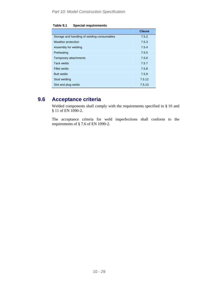
Other special requirements are described in EN 1090-2, as indicated in Table 9.1:
Part 10: Model Construction Specification
10 - 29
Table 9.1 Special requirements
Clause
Storage and handling of welding consumables 7.5.2
Weather protection 7.5.3
Assembly for welding 7.5.4
Preheating 7.5.5
Temporary attachments 7.5.6
Tack welds 7.5.7
Fillet welds 7.5.8
Butt welds 7.5.9
Stud welding 7.5.12
Slot and plug welds 7.5.13
9.6 Acceptance criteria Welded components shall comply with the requirements specified in § 10 and § 11 of EN 1090-2.
The acceptance criteria for weld imperfections shall conform to the requirements of § 7.6 of EN 1090-2.
Part 10: Model Construction Specification
10 - 30
10 MECHANICAL FASTENING
Section 8 of EN 1090-2 covers requirements for shop and site fastening, including the fixing of profiled sheeting; it refers to bolting assemblies consisting of matching bolts, nuts and washers (as necessary).
Contract documents shall specify if, in addition to tightening, other measures or means are to be used to secure the nuts.
Minimum nominal fastener diameter, bolt length, length of protrusion, length of the unthreaded bolt shaft and clamp length shall comply with the requirements of § 8.2.2 of EN 1090-2.
Requirements given in § 8.2.3 of EN 1090-2 for washers shall apply.
Tightening of non-preloaded bolts shall comply with the requirements of § 8.3 of EN 1090-2.
Precautions and preparation of contact surfaces in slip resistant connections shall comply with the requirements of § 8.4 and Table 18 of EN 1090-2. Slip factor shall be determined by test as specified in Annex G of EN 1090-2.
Tightening methods of preloaded bolts shall comply with the requirements of § 8.5 of EN 1090-2, and shall be specified in the contract documents.

Part 10: Model Construction Specification
10 - 31
11 ERECTION
Section 9 of EN 1090-2 gives requirements for erection and other work undertaken on site including grouting of bases as well as those relevant to the suitability of the site for safe erection and for accurately prepared supports.
Erection shall not commence until the site for the construction works complies with the technical requirements with respect to the safety of the works. Safety items related to site conditions are listed in § 9.2 of EN 1090-2.
If the structural stability in the part-erected condition is not evident, a safe method of erection, on which the design was based, shall be provided. Items related to the design basis method of erection are listed in § 9.3.1 of EN 1090-2.
A method statement describing the steelwork contractor's erection method shall be prepared and checked in accordance with design rules. The erection method statement shall describe procedures to be used to safely erect the steelwork and shall take into account the technical requirements regarding the safety of the works. The erection method statement shall address all relevant items in § 9.3.1 of EN 1090-2; additional items are listed in § 9.3.2 of EN 1090-2.
Erection drawings or equivalent instructions, in accordance with the requirements of § 9.6.1 of EN 1090-2, shall be provided and form part of the erection method statement.
Site measurements for the works shall be in accordance with the survey requirements of § 9.4 of EN 1090-2.
The condition and location of the supports shall be checked visually and by appropriate measurement before the commencement of erection. If supports are unsuited to erection, they shall be corrected prior to the commencement of erection. Nonconformities shall be documented.
All foundations, foundation bolts and other supports for the steelwork shall be suitably prepared to receive the steel structure. Installation of structural bearings shall comply with the requirements of EN 1337-11. Erection shall not commence until the location and levels of the supports, anchors or bearings comply with the acceptance criteria in § 11.2 of EN 1090-2, or an appropriate amendment to the specified requirements.
If foundation bolts are to be pre-stressed, arrangements shall be made that the upper 100 mm of the bolt, as a minimum, has no adhesion to the concrete. Foundation bolts intended to move in sleeves shall be provided with sleeves three times the diameter of the bolt with a minimum diameter of 75 mm.
Whilst erection is proceeding, the supports for the steelwork shall be maintained in an equivalent condition to their condition at the commencement of erection.

Part 10: Model Construction Specification
10 - 32
Areas of supports that require protection against rust staining shall be identified and appropriate protection provided.
Compensation for settlement of supports is acceptable, unless otherwise specified in the contract documents. This shall be done by grouting or packing between steelwork and support. The compensation will generally be placed beneath the bearing.
Shims and other supporting devices used as temporary supports under base plates shall be placed in accordance with the requirements of § 8.3, 8.5.1, § 9.5.4 and § 9.6.5.3 of EN 1090-2.
Grouting, sealing and anchoring shall be set in accordance with their specification and the requirements of § 5.8, 9.5.5 and § 9.5.6 of EN 1090-2.
Components that are individually assembled or erected at the site shall be allocated an erection mark, in accordance with the requirements of § 6.2 and § 9.6.2 of EN 1090-2.
Handling and storage on site shall comply with the requirements of § 6.3 and § 9.6.3 of EN 1090-2.
Any site trial erection shall be performed in accordance with the requirements of § 6.10 and § 9.6.10 of EN 1090-2.
The erection of the steelwork shall be carried out in conformity with the erection method statement and in such a way as to ensure stability at all times.
Foundation bolts shall not be used to secure unguyed columns against overturning unless they have been checked for this design situation.
Throughout the erection of the structure, the steelwork shall be made safe against temporary erection loads, including those due to erection equipment or its operation and against the effects of wind loads on the unfinished structure.
At least one third of the permanent bolts in each connection should be installed before that connection can be considered to contribute to stability of the part completed structure.
All temporary bracing and temporary restraints shall be left in position until erection is sufficiently advanced to allow its safe removal.
All connections for temporary components provided for erection purposes shall be made in accordance with the requirements of EN 1090-2 and in such a way that they do not weaken the permanent structure or impair its serviceability.
If backing bars and draw cleats are used to support the structure during welding, it shall be ensured that they are sufficiently strong and that their retaining welds are appropriate for the erection load conditions.
If the erection procedure involves rolling or otherwise moving the structure, or part of the structure, into its final position after assembly, provision shall be
Part 10: Model Construction Specification
10 - 33
made for controlled braking of the moving mass. Provision for reversing the direction of movement may need to be considered.
All temporary anchoring devices shall be made secure against unintentional release.
Only jacks that can be locked in any position under load shall be used unless other safety provisions are made.
Care shall be taken that no part of the structure is permanently distorted or over-stressed by stacking of steelwork components or by erection loads during the erection process.
Each part of the structure shall be aligned as soon as practicable after it has been erected and final assembly completed as soon as possible thereafter.
Permanent connections shall not be made between components until sufficient of the structure has been aligned, levelled, plumbed and temporarily connected to ensure that components will not be displaced during subsequent erection or alignment of the remainder of the structure.
Alignment of the structure and lack-of-fit in connections may be adjusted by the use of shims (see above). If lack-of-fit between erected components cannot be corrected by the use of shims, components of the structure shall be locally modified in accordance with the methods specified in EN 1090-2. The modifications shall not compromise the performance of the structure in the temporary or permanent state. This work may be executed on site. Care shall be taken with structures built of welded latticed components and space structures to ensure that they are not subjected to excessive forces in an attempt to force a fit against their inherent rigidity.
Unless otherwise prohibited in the contract documents, drifts may be used to align connections. Elongation of holes for bolts used for transmission of loads shall not be more than the values given in § 6.9 of EN 1090-2.
In case of misalignment of holes for bolts, the method of correction shall be checked for consistency with the requirements of § 12 of EN 1090-2.
Realigned holes may be proven to comply with the oversize or slotted hole requirements specified in 8.1 of EN 1090-2, provided the load path has been checked.
Correction of misalignment by reaming or using a hollow milling cutter is preferred, but if the use of other cutting methods is unavoidable, the internal finish of all holes formed by these other methods shall be specifically checked for consistency with the requirements of § 6 of EN 1090-2.
Completed site connections shall be checked in accordance with 12.5 of EN 1090-2.
Erection tolerances are detailed in § 11.2.3 and Tables D.1.11 to D.1.15 and Tables D.2.19 to D.2.28 of Annex D of EN 1090-2.
Part 10: Model Construction Specification
10 - 34
12 CONSTRUCTOR’S DOCUMENTATION
Quality documentation, mandatory for Execution Classes EXC2 to EXC4, is defined in § 4.2.1 of EN 1090-2.
If required, a quality plan (defined in EN ISO 9000) for the execution of the works is described in § 4.2.2 of EN 1090-2. Annex C of EN 1090-2 gives a check-list for the content of a quality plan recommended for the execution of structural steelwork with reference to the general guidelines in ISO 10005.
Method statements giving detailed work instructions shall comply with the technical requirements relating to the safety of the erection works as given in § 9.2 and § 9.3 of EN 1090-2.
Sufficient documentation shall be prepared during execution and as a record of the as-built structure to demonstrate that the works have been carried out according to the execution specification.
Design and structural engineering documentation shall be prepared before execution of the works, and approved by any approval body designated by the Owner. The documentation should contain:
Design assumptions
Software used (if any)
Member and joint design verification
General Arrangement drawings and joint details.
Part 10: Model Construction Specification
10 - 35
13 INTERFACES OF THE STEEL STRUCTURE
13.1 Interface to concrete surfaces Information showing holding-down bolts and the interface of steelwork components to foundations shall include a Foundation Plan showing the base location, position and orientation of columns, the marks of all columns, any other components in direct contact with the foundations, their base location and level, and the datum level.
Similar information shall also be provided for components connecting to walls and other concrete surfaces.
Complete details of fixing steel and bolts to the foundations or walls, method of adjustment and packing space shall be provided.
Before erection of steelwork starts, the steelwork contractor shall inspect the prepared foundations and holding-down bolts for position and level; if he finds any discrepancies which are outside the deviations specified in § D.2.20 of EN 1090-2, he shall request that remedial work be carried out before erection commences.
Shims and other supporting devices used as temporary supports under base plates shall present a flat surface to the steel and be of adequate size, strength and rigidity to avoid local crushing of the substructure concrete or masonry.
If packings are subsequently to be grouted, they shall be placed so that the grout totally encloses them with a minimum cover of 25 mm unless otherwise specified.
If packings are left in position after grouting, they shall be made from materials with the same durability as the structure.
If adjustment to the position of the base is achieved using levelling nuts on the foundation bolts under the base plate, these may be left in position unless otherwise specified. The nuts shall be selected to ensure that they are suitable to maintain the stability of the part-erected structure but not to jeopardize the performance of the foundation bolt in service.
If spaces under base plates are to be grouted, fresh material shall be used in accordance with § 5.8 of EN 1090-2.
Grouting shall not be carried out under column base plates until a sufficient portion of the structure has been aligned, levelled, plumbed and adequately braced.
Grouting material shall be used as follows:
The material shall be mixed and used in accordance with product manufacturer's recommendations notably regarding its consistency when used. Material shall not be mixed or used below 0°C unless the manufacturer's recommendations permit it.
Part 10: Model Construction Specification
10 - 36
The material shall be poured under a suitable head so that the space is completely filled.
Tamping and ramming against properly fixed supports shall be used if specified and/or recommended by the grout manufacturer.
Vent holes shall be provided as necessary.
Immediately before grouting, the space under the steel base plate shall be free from liquids, ice, debris and contaminants.
If treatment of steelwork, bearings and concrete surfaces is required before grouting, it shall be specified in the contract documents.
Care shall be taken that the external profile of grouting allows water to be drained away from structural steel components. If there is a danger of water or corrosive liquid becoming entrapped during service, the grout around base plates shall not be surcharged such that it rises above the lowest surface of the base plate and the geometry of the concrete grout shall form an angle from the base plate.
If no grouting is needed, and the edges of the base plate are to be sealed, the method shall be specified.
Anchoring devices in concrete parts of the structure or adjacent structures shall be set in accordance with their specification. Suitable measures shall be taken to avoid damage to concrete in order to achieve the necessary anchoring resistance.
Foundations shall be adequately designed by a qualified foundation engineer to support the building reactions and other loads which may be imposed by the building use. The design shall be based on the specific soil conditions of the building site.
13.2 Interface to neighbouring constructions The mutual influence of neighbouring constructions for wind or snow actions must be carefully considered. Design wind and snow loads may vary considerably regarding the site and the construction environment, hence, precise indications shall be given, in the contract documents, concerning the surrounding constructions.
Part 10: Model Construction Specification
10 - 37
APPENDIX A MODEL PROJECT SPECIFICATION
The execution of steelwork for single-storey buildings in Europe will generally be specified to be in accordance with EN 1090-2, and the design to be in accordance with applicable parts of the Eurocode Standards. These Standards, which cover technical requirements for a wide range of steel structures, include clauses where the execution/design specification for the works is required to give additional information or where it has the option to specify other requirements.
Appendix A offers a set of clauses that may be used for single-storey steel building projects to supplement and quantify the rules of the European Standards.
The clauses are arranged in a two-column format. The left column contains the proposed clauses. The right column gives a commentary to several clauses, for the information of the person drawing up project documents; those commentaries are not intended to be included within the execution specification. The model specification must be made specific to the construction project by completing the relevant clauses with appropriate information.
The model project specification proposed in this Appendix covers structural steelwork produced from hot rolled structural steel products only. It does not cover structural steelwork produced from cold formed structural steel (only cold formed profiled steel sheeting and cold formed stressed-skin sheeting used as a structural diaphragm are herein covered), structural hollow sections, channels and tubes and stainless steel products. This model project specification relates principally to conventional construction using constituent products to the standards referenced in EN 1090-2. If more complex forms of construction are involved or other products are used, designers need to consider any modifications that might be needed to the execution specification to ensure that the desired quality and/or functionality are achieved.
For consistency, in Appendix A, those clause headings that are numbered and in bold, correspond to the Section headings of this document.
Part 10: Model Construction Specification
10 - 38
Proposed Clauses Commentary
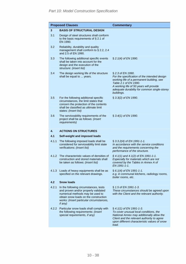
3 BASIS OF STRUCTURAL DESIGN
3.1 Design of steel structures shall conform to the basic requirements of § 2.1 of EN 1990.
3.2 Reliability, durability and quality management shall conform to § 2.2, 2.4 and 2.5 of EN 1990.
3.3 The following additional specific events shall be taken into account for the design and the execution of the structure: (insert list)
§ 2.1(4) of EN 1990.
3.4 The design working life of the structure shall be equal to ... years.
§ 2.3 of EN 1990. For the specification of the intended design working life of a permanent building, see Table 2.1 of EN 1990. A working life of 50 years will provide adequate durability for common single-storey buildings.
3.5 For the following additional specific circumstances, the limit states that concern the protection of the contents shall be classified as ultimate limit states: (insert list)
§ 3.3(2) of EN 1990.
3.6 The serviceability requirements of the project shall be as follows: (insert requirements)
§ 3.4(1) of EN 1990.
4. ACTIONS ON STRUCTURES
4.1 Self-weight and imposed loads
4.1.1 The following imposed loads shall be considered for serviceability limit state verifications: (insert list)
§ 3.3.2(4) of EN 1991-1-1. In accordance with the service conditions and the requirements concerning the performance of the structure.
4.1.2 The characteristic values of densities of construction and stored materials shall be taken as follows: (insert list)
§ 4.1(1) and 4.1(2) of EN 1991-1-1. Especially for materials which are not covered by the Tables in Annex A of EN 1991-1-1.
4.1.3 Loads of heavy equipments shall be as specified on the relevant drawings.
§ 6.1(4) of EN 1991-1-1. e.g. in communal kitchens, radiology rooms, boiler rooms, etc.
4.2 Snow loads
4.2.1 In the following circumstances, tests and proven and/or properly validated numerical methods may be used to obtain snow loads on the construction works: (insert particular circumstances, if any)
§ 1.5 of EN 1991-1-3. These circumstances should be agreed upon with the Client and the relevant authority.
4.2.2 Particular snow loads shall comply with the following requirements: (insert special requirements, if any)
§ 4.1(1) of EN 1991-1-3. To cover unusual local conditions, the National Annex may additionally allow the Client and the relevant authority to agree upon different characteristic values of snow load.
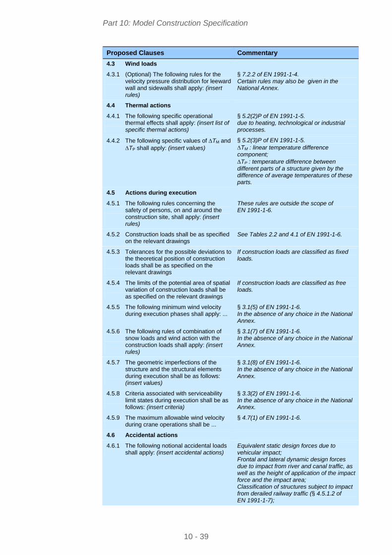
Part 10: Model Construction Specification
10 - 39
Proposed Clauses Commentary
4.3 Wind loads
4.3.1 (Optional) The following rules for the velocity pressure distribution for leeward wall and sidewalls shall apply: (insert rules)
§ 7.2.2 of EN 1991-1-4. Certain rules may also be given in the National Annex.
4.4 Thermal actions
4.4.1 The following specific operational thermal effects shall apply: (insert list of specific thermal actions)
§ 5.2(2)P of EN 1991-1-5. due to heating, technological or industrial processes.
4.4.2 The following specific values of TM and TP shall apply: (insert values)
§ 5.2(3)P of EN 1991-1-5. TM : linear temperature difference component; TP : temperature difference between different parts of a structure given by the difference of average temperatures of these parts.
4.5 Actions during execution
4.5.1 The following rules concerning the safety of persons, on and around the construction site, shall apply: (insert rules)
These rules are outside the scope of EN 1991-1-6.
4.5.2 Construction loads shall be as specified on the relevant drawings
See Tables 2.2 and 4.1 of EN 1991-1-6.
4.5.3 Tolerances for the possible deviations to the theoretical position of construction loads shall be as specified on the relevant drawings
If construction loads are classified as fixed loads.
4.5.4 The limits of the potential area of spatial variation of construction loads shall be as specified on the relevant drawings
If construction loads are classified as free loads.
4.5.5 The following minimum wind velocity during execution phases shall apply: ...
§ 3.1(5) of EN 1991-1-6. In the absence of any choice in the National Annex.
4.5.6 The following rules of combination of snow loads and wind action with the construction loads shall apply: (insert rules)
§ 3.1(7) of EN 1991-1-6. In the absence of any choice in the National Annex.
4.5.7 The geometric imperfections of the structure and the structural elements during execution shall be as follows: (insert values)
§ 3.1(8) of EN 1991-1-6. In the absence of any choice in the National Annex.
4.5.8 Criteria associated with serviceability limit states during execution shall be as follows: (insert criteria)
§ 3.3(2) of EN 1991-1-6. In the absence of any choice in the National Annex.
4.5.9 The maximum allowable wind velocity during crane operations shall be ...
§ 4.7(1) of EN 1991-1-6.
4.6 Accidental actions
4.6.1 The following notional accidental loads shall apply: (insert accidental actions)
Equivalent static design forces due to vehicular impact; Frontal and lateral dynamic design forces due to impact from river and canal traffic, as well as the height of application of the impact force and the impact area; Classification of structures subject to impact from derailed railway traffic (§ 4.5.1.2 of EN 1991-1-7);
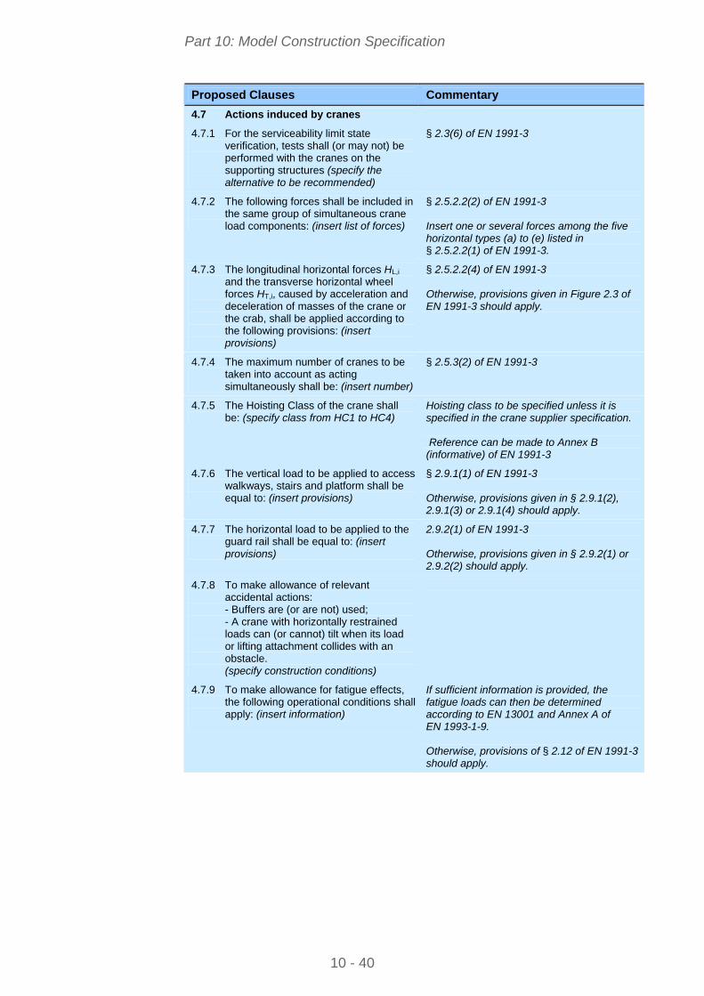
Part 10: Model Construction Specification
10 - 40
Proposed Clauses Commentary
4.7 Actions induced by cranes
4.7.1 For the serviceability limit state verification, tests shall (or may not) be performed with the cranes on the supporting structures (specify the alternative to be recommended)
§ 2.3(6) of EN 1991-3
4.7.2 The following forces shall be included in the same group of simultaneous crane load components: (insert list of forces)
§ 2.5.2.2(2) of EN 1991-3 Insert one or several forces among the five horizontal types (a) to (e) listed in § 2.5.2.2(1) of EN 1991-3.
4.7.3 The longitudinal horizontal forces HL,i and the transverse horizontal wheel forces HT,i, caused by acceleration and deceleration of masses of the crane or the crab, shall be applied according to the following provisions: (insert provisions)
§ 2.5.2.2(4) of EN 1991-3 Otherwise, provisions given in Figure 2.3 of EN 1991-3 should apply.
4.7.4 The maximum number of cranes to be taken into account as acting simultaneously shall be: (insert number)
§ 2.5.3(2) of EN 1991-3
4.7.5 The Hoisting Class of the crane shall be: (specify class from HC1 to HC4)
Hoisting class to be specified unless it is specified in the crane supplier specification. Reference can be made to Annex B (informative) of EN 1991-3
4.7.6 The vertical load to be applied to access walkways, stairs and platform shall be equal to: (insert provisions)
§ 2.9.1(1) of EN 1991-3 Otherwise, provisions given in § 2.9.1(2), 2.9.1(3) or 2.9.1(4) should apply.
4.7.7 The horizontal load to be applied to the guard rail shall be equal to: (insert provisions)
2.9.2(1) of EN 1991-3 Otherwise, provisions given in § 2.9.2(1) or 2.9.2(2) should apply.
4.7.8 To make allowance of relevant accidental actions: - Buffers are (or are not) used; - A crane with horizontally restrained loads can (or cannot) tilt when its load or lifting attachment collides with an obstacle.
(specify construction conditions)
4.7.9 To make allowance for fatigue effects, the following operational conditions shall apply: (insert information)
If sufficient information is provided, the fatigue loads can then be determined according to EN 13001 and Annex A of EN 1993-1-9. Otherwise, provisions of § 2.12 of EN 1991-3 should apply.
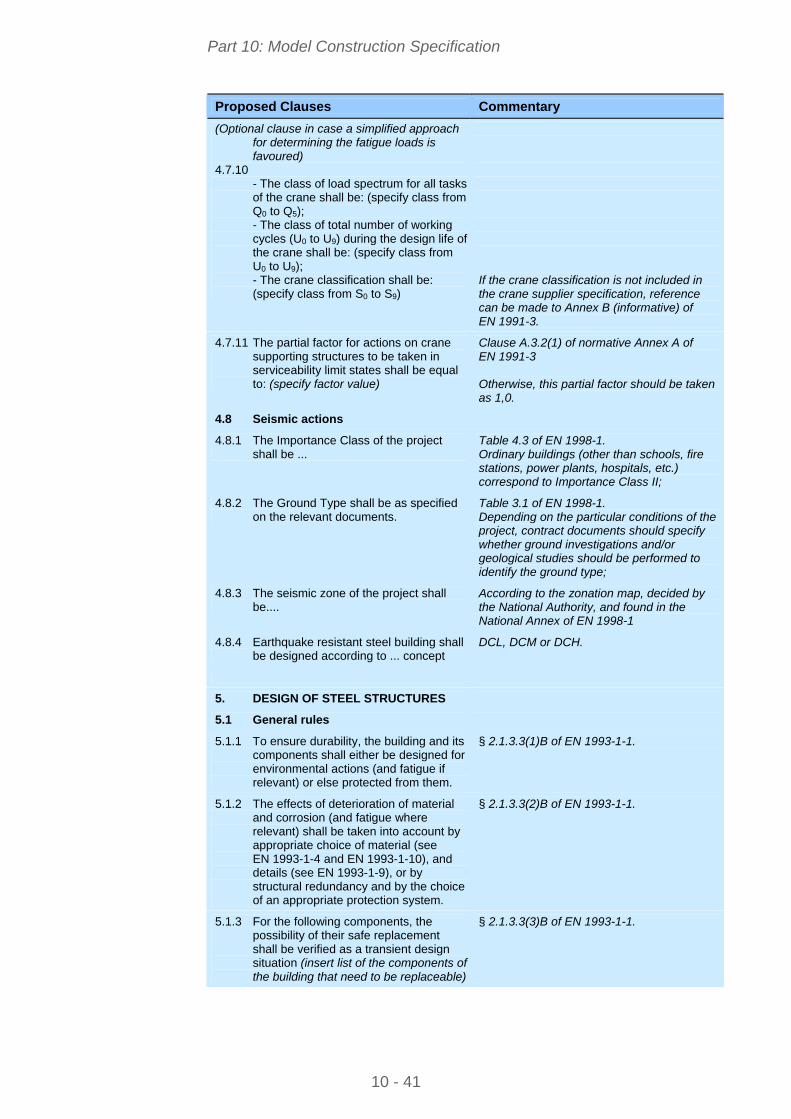
Part 10: Model Construction Specification
10 - 41
Proposed Clauses Commentary
(Optional clause in case a simplified approach for determining the fatigue loads is favoured)
4.7.10 - The class of load spectrum for all tasks
of the crane shall be: (specify class from Q0 to Q5);
- The class of total number of working cycles (U0 to U9) during the design life of the crane shall be: (specify class from U0 to U9);
- The crane classification shall be: (specify class from S0 to S9)
If the crane classification is not included in the crane supplier specification, reference can be made to Annex B (informative) of EN 1991-3.
4.7.11 The partial factor for actions on crane supporting structures to be taken in serviceability limit states shall be equal to: (specify factor value)
Clause A.3.2(1) of normative Annex A of EN 1991-3 Otherwise, this partial factor should be taken as 1,0.
4.8 Seismic actions
4.8.1 The Importance Class of the project shall be ...
Table 4.3 of EN 1998-1. Ordinary buildings (other than schools, fire stations, power plants, hospitals, etc.) correspond to Importance Class II;
4.8.2 The Ground Type shall be as specified on the relevant documents.
Table 3.1 of EN 1998-1. Depending on the particular conditions of the project, contract documents should specify whether ground investigations and/or geological studies should be performed to identify the ground type;
4.8.3 The seismic zone of the project shall be....
According to the zonation map, decided by the National Authority, and found in the National Annex of EN 1998-1
4.8.4 Earthquake resistant steel building shall be designed according to ... concept
DCL, DCM or DCH.
5. DESIGN OF STEEL STRUCTURES
5.1 General rules
5.1.1 To ensure durability, the building and its components shall either be designed for environmental actions (and fatigue if relevant) or else protected from them.
§ 2.1.3.3(1)B of EN 1993-1-1.
5.1.2 The effects of deterioration of material and corrosion (and fatigue where relevant) shall be taken into account by appropriate choice of material (see EN 1993-1-4 and EN 1993-1-10), and details (see EN 1993-1-9), or by structural redundancy and by the choice of an appropriate protection system.
§ 2.1.3.3(2)B of EN 1993-1-1.
5.1.3 For the following components, the possibility of their safe replacement shall be verified as a transient design situation (insert list of the components of the building that need to be replaceable)
§ 2.1.3.3(3)B of EN 1993-1-1.
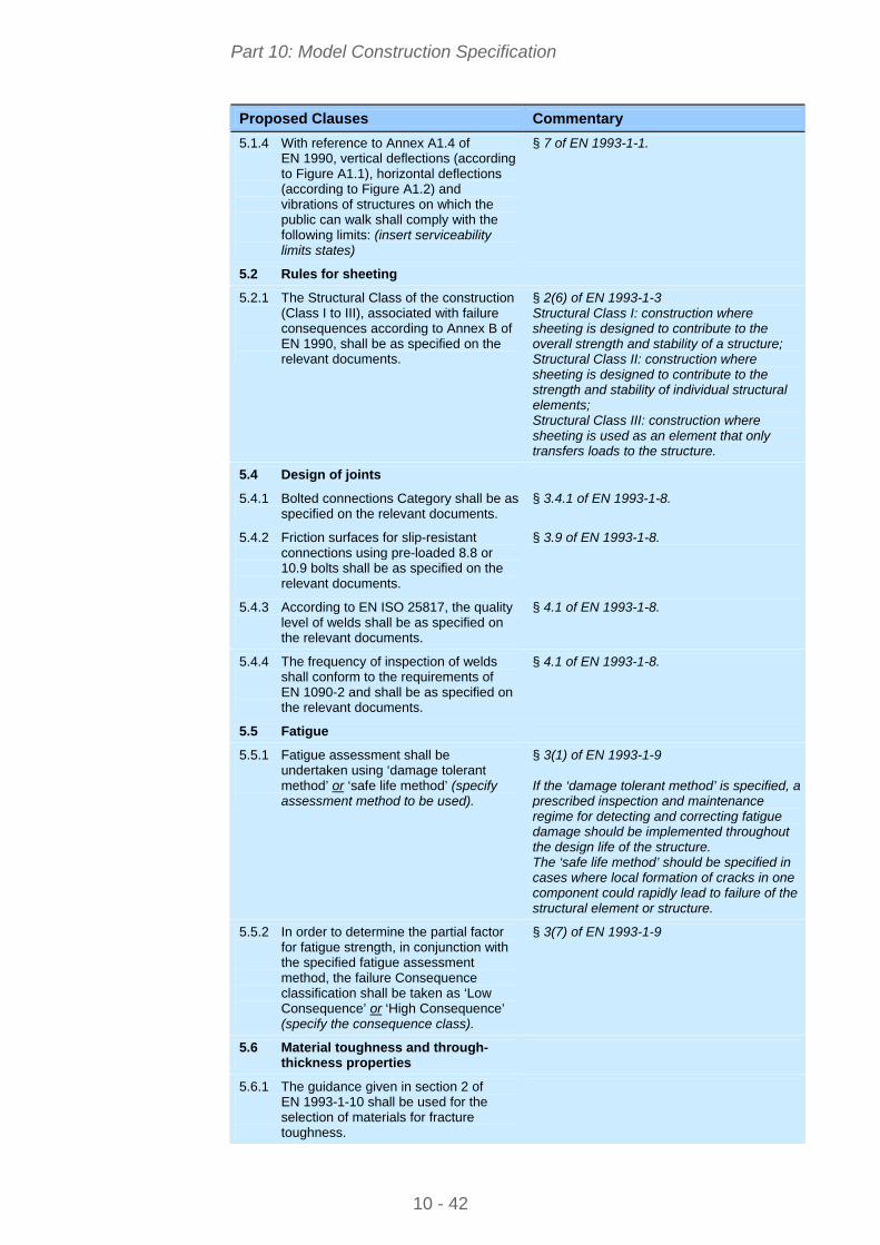
Part 10: Model Construction Specification
10 - 42
Proposed Clauses Commentary
5.1.4 With reference to Annex A1.4 of EN 1990, vertical deflections (according to Figure A1.1), horizontal deflections (according to Figure A1.2) and vibrations of structures on which the public can walk shall comply with the following limits: (insert serviceability limits states)
§ 7 of EN 1993-1-1.
5.2 Rules for sheeting
5.2.1 The Structural Class of the construction (Class I to III), associated with failure consequences according to Annex B of EN 1990, shall be as specified on the relevant documents.
§ 2(6) of EN 1993-1-3 Structural Class I: construction where sheeting is designed to contribute to the overall strength and stability of a structure; Structural Class II: construction where sheeting is designed to contribute to the strength and stability of individual structural elements; Structural Class III: construction where sheeting is used as an element that only transfers loads to the structure.
5.4 Design of joints
5.4.1 Bolted connections Category shall be as specified on the relevant documents.
§ 3.4.1 of EN 1993-1-8.
5.4.2 Friction surfaces for slip-resistant connections using pre-loaded 8.8 or 10.9 bolts shall be as specified on the relevant documents.
§ 3.9 of EN 1993-1-8.
5.4.3 According to EN ISO 25817, the quality level of welds shall be as specified on the relevant documents.
§ 4.1 of EN 1993-1-8.
5.4.4 The frequency of inspection of welds shall conform to the requirements of EN 1090-2 and shall be as specified on the relevant documents.
§ 4.1 of EN 1993-1-8.
5.5 Fatigue
5.5.1 Fatigue assessment shall be undertaken using ‘damage tolerant method’ or ‘safe life method’ (specify assessment method to be used).
§ 3(1) of EN 1993-1-9 If the ‘damage tolerant method’ is specified, a prescribed inspection and maintenance regime for detecting and correcting fatigue damage should be implemented throughout the design life of the structure. The ‘safe life method’ should be specified in cases where local formation of cracks in one component could rapidly lead to failure of the structural element or structure.
5.5.2 In order to determine the partial factor for fatigue strength, in conjunction with the specified fatigue assessment method, the failure Consequence classification shall be taken as ‘Low Consequence’ or ‘High Consequence’ (specify the consequence class).
§ 3(7) of EN 1993-1-9
5.6 Material toughness and through-thickness properties
5.6.1 The guidance given in section 2 of EN 1993-1-10 shall be used for the selection of materials for fracture toughness.
Part 10: Model Construction Specification
10 - 43
Proposed Clauses Commentary
5.6.2 The guidance given in section 3 of EN 1993-1-10 shall be used for the selection of materials for through-thickness properties.
5.7 Crane supporting structures
5.7.1 Where crane rails are assumed to contribute to the strength or stiffness of a runway beam, the properties of the combined cross-section shall be determined as follows:
(Specify the appropriate allowances for wear to be made).
§ 4(3) of EN 1993-6
5.7.2 Where actions from soil subsidence or seismic actions are expected, tolerances for vertical and horizontal imposed deformations shall be taken as follows:
(Specify the appropriate allowances).
§ 4(4) of EN 1993-6 These allowances should be agreed with the crane supplier, and included in the inspection and maintenance plans.
5.7.3 The limits for deformations and displacements shall be taken as follows: (specify the specific limits together with the serviceability load combinations under which they apply).
§ 7.3(1) of EN 1993-6
6. EXECUTION SPECIFICATION
6.1 General
6.1.1 The requirements for the execution of structural steelwork for the project are given in the following documents: (Insert list)
Insert a list of the relevant drawings and other documents, including reference to EN 1090-2.
6.2 Execution Class
6.2.1 For building structures, EXC2 shall generally apply, except where specified otherwise on the drawings.
The use of EXC2 as the default class will provide adequate reliability for most elements of ordinary buildings. For some structures, a greater scope of inspection and testing and/or higher quality level acceptance criteria may be required, either generally or for particular details. Particular details where this is required, such as where special inspection and testing is required, should be indicated on the drawings. Table A.3 of EN 1090-2 gives a list of requirements related to execution classes; Annex B of EN 1090-2 gives guidance for the choice of execution classes; The choice of execution classes is related to production categories and service categories, with links to consequence classes as defined in Annex B of EN 1990.
6.3 Preparation grades
6.3.1 The preparation grade of all surfaces to which paints and related products are to be applied shall be ... Otherwise, The expected life of the corrosion protection shall be ... years or corrosivity category shall be ...
Preparation grades (P1 to P3 according to ISO 8501-3) are related to the expected life of the corrosion protection and corrosivity category as defined in § 10 of EN 1090-2.
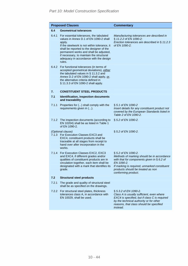
Part 10: Model Construction Specification
10 - 44
Proposed Clauses Commentary
6.4 Geometrical tolerances
6.4.1 For essential tolerances, the tabulated values in Annex D.1 of EN 1090-2 shall apply. If the steelwork is not within tolerance, it shall be reported to the designer of the permanent works and shall be adjusted, if necessary, to maintain the structural adequacy in accordance with the design rules.
Manufacturing tolerances are described in § 11.2.2 of EN 1090-2; Erection tolerances are described in § 11.2.3 of EN 1090-2;
6.4.2 For functional tolerances (in terms of accepted geometrical deviations), either the tabulated values in § 11.3.2 and Annex D.2 of EN 1090-2 shall apply, or, the alternative criteria defined in § 11.3.3 of EN 1090-2 shall apply.
7. CONSTITUENT STEEL PRODUCTS
7.1 Identification, inspection documents and traceability
7.1.1 Properties for (...) shall comply with the requirements given in (...).
§ 5.1 of EN 1090-2 Insert details for any constituent product not covered by the European Standards listed in Table 2 of EN 1090-2.
7.1.2 The inspection documents (according to EN 10204) shall be as listed in Table 1 of EN 1090-2.
§ 5.2 of EN 1090-2.
(Optional clause) 7.1.3 For Execution Classes EXC3 and
EXC4, constituent products shall be traceable at all stages from receipt to hand over after incorporation in the works.
§ 5.2 of EN 1090-2.
7.1.4 For Execution Classes EXC2, EXC3 and EXC4, if different grades and/or qualities of constituent products are in circulation together, each item shall be designated with a mark that identifies its grade.
§ 5.2 of EN 1090-2. Methods of marking should be in accordance with that for components given in § 6.2 of EN 1090-2. If marking is required, unmarked constituent products should be treated as non conforming product.
7.2 Structural steel products
7.2.1 The grade and quality of structural steel shall be as specified on the drawings.
7.2.2 For structural steel plates, thickness tolerances class A, in accordance with EN 10029, shall be used.
§ 5.3.2 of EN 1090-2. Class A is usually sufficient, even where EXC4 is specified, but if class C is required by the technical authority or for other reasons, that class should be specified instead.
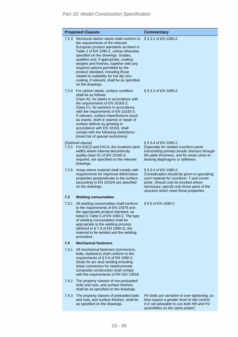
Part 10: Model Construction Specification
10 - 45
Proposed Clauses Commentary
7.2.3 Structural carbon steels shall conform to the requirements of the relevant European product standards as listed in Table 2 of EN 1090-2, unless otherwise specified on the drawings. Grades, qualities and, if appropriate, coating weights and finishes, together with any required options permitted by the product standard, including those related to suitability for hot dip zinc-coating, if relevant, shall be as specified on the drawings.
§ 5.3.1 of EN 1090-2.
7.2.4 For carbon steels, surface condition shall be as follows: Class A2, for plates in accordance with the requirements of EN 10163-2; Class C1, for sections in accordance with the requirements of EN 10163-3. If relevant, surface imperfections (such as cracks, shell or seams) or repair of surface defects by grinding in accordance with EN 10163, shall comply with the following restrictions : (insert list of special restrictions)
§ 5.3.3 of EN 1090-2.
(Optional clause) 7.2.5 For EXC3 and EXC4, the locations (and
width) where internal discontinuity quality class S1 of EN 10160 is required, are specified on the relevant drawings.
§ 5.3.4 of EN 1090-2. Especially for welded cruciform joints transmitting primary tensile stresses through the plate thickness, and for areas close to bearing diaphragms or stiffeners.
7.2.6 Areas where material shall comply with requirements for improved deformation properties perpendicular to the surface (according to EN 10164) are specified on the drawings.
§ 5.3.4 of EN 1090-2. Consideration should be given to specifying such material for cruciform, T and corner joints. Should only be invoked where necessary; specify only those parts of the structure which need these properties.
7.3 Welding consumables
7.3.1 All welding consumables shall conform to the requirements of EN 13479 and the appropriate product standard, as listed in Table 5 of EN 1090-2. The type of welding consumables shall be appropriate to the welding process (defined in § 7.3 of EN 1090-2), the material to be welded and the welding procedure.
§ 5.5 of EN 1090-2.
7.4 Mechanical fasteners
7.4.1 All mechanical fasteners (connectors, bolts, fasteners) shall conform to the requirements of § 5.6 of EN 1090-2. Studs for arc stud welding including shear connectors for steel/concrete composite construction shall comply with the requirements of EN ISO 13918.
7.4.2 The property classes of non-preloaded bolts and nuts, and surface finishes, shall be as specified on the drawings.
7.4.3 The property classes of preloaded bolts and nuts, and surface finishes, shall be as specified on the drawings.
HV bolts are sensitive to over-tightening, so they require a greater level of site control. It is not advisable to use both HR and HV assemblies on the same project.
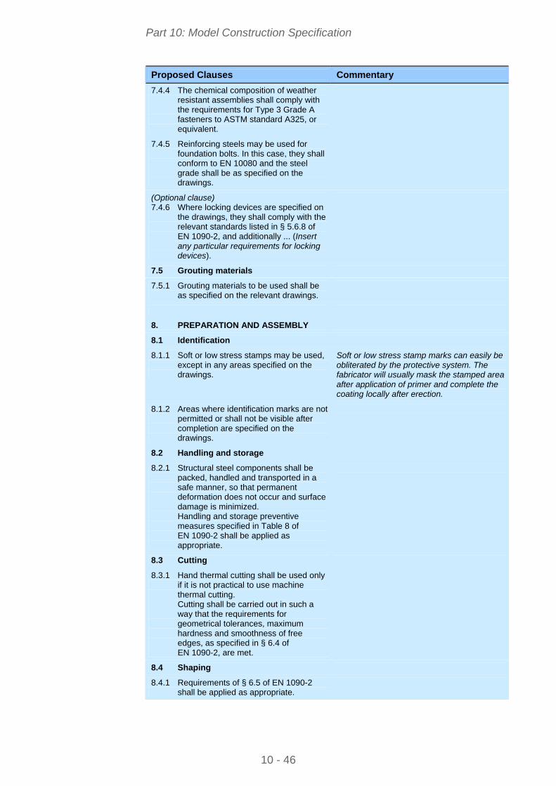
Part 10: Model Construction Specification
10 - 46
Proposed Clauses Commentary
7.4.4 The chemical composition of weather resistant assemblies shall comply with the requirements for Type 3 Grade A fasteners to ASTM standard A325, or equivalent.
7.4.5 Reinforcing steels may be used for foundation bolts. In this case, they shall conform to EN 10080 and the steel grade shall be as specified on the drawings.
(Optional clause) 7.4.6 Where locking devices are specified on
the drawings, they shall comply with the relevant standards listed in § 5.6.8 of EN 1090-2, and additionally ... (Insert any particular requirements for locking devices).
7.5 Grouting materials
7.5.1 Grouting materials to be used shall be as specified on the relevant drawings.
8. PREPARATION AND ASSEMBLY
8.1 Identification
8.1.1 Soft or low stress stamps may be used, except in any areas specified on the drawings.
Soft or low stress stamp marks can easily be obliterated by the protective system. The fabricator will usually mask the stamped area after application of primer and complete the coating locally after erection.
8.1.2 Areas where identification marks are not permitted or shall not be visible after completion are specified on the drawings.
8.2 Handling and storage
8.2.1 Structural steel components shall be packed, handled and transported in a safe manner, so that permanent deformation does not occur and surface damage is minimized. Handling and storage preventive measures specified in Table 8 of EN 1090-2 shall be applied as appropriate.
8.3 Cutting
8.3.1 Hand thermal cutting shall be used only if it is not practical to use machine thermal cutting. Cutting shall be carried out in such a way that the requirements for geometrical tolerances, maximum hardness and smoothness of free edges, as specified in § 6.4 of EN 1090-2, are met.
8.4 Shaping
8.4.1 Requirements of § 6.5 of EN 1090-2 shall be applied as appropriate.
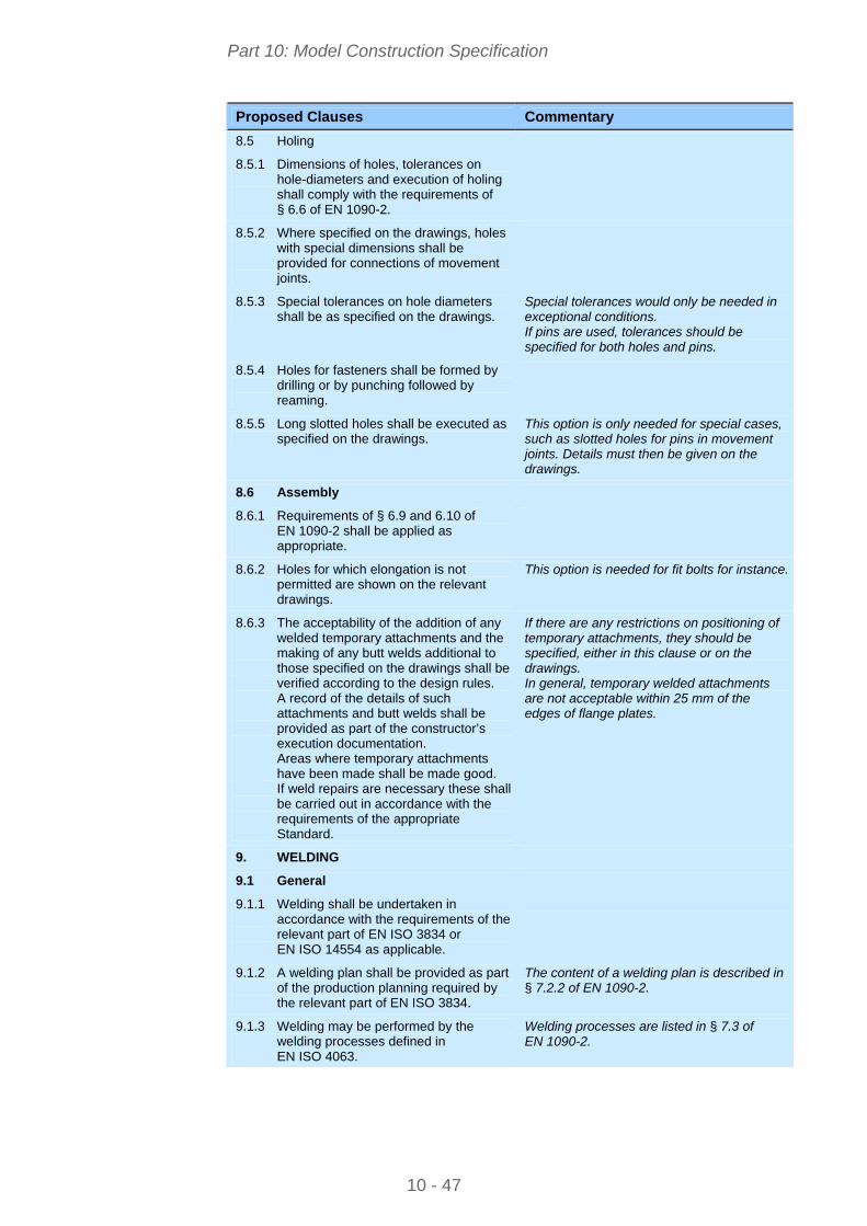
Part 10: Model Construction Specification
10 - 47
Proposed Clauses Commentary
8.5 Holing
8.5.1 Dimensions of holes, tolerances on hole-diameters and execution of holing shall comply with the requirements of § 6.6 of EN 1090-2.
8.5.2 Where specified on the drawings, holes with special dimensions shall be provided for connections of movement joints.
8.5.3 Special tolerances on hole diameters shall be as specified on the drawings.
Special tolerances would only be needed in exceptional conditions. If pins are used, tolerances should be specified for both holes and pins.
8.5.4 Holes for fasteners shall be formed by drilling or by punching followed by reaming.
8.5.5 Long slotted holes shall be executed as specified on the drawings.
This option is only needed for special cases, such as slotted holes for pins in movement joints. Details must then be given on the drawings.
8.6 Assembly
8.6.1 Requirements of § 6.9 and 6.10 of EN 1090-2 shall be applied as appropriate.
8.6.2 Holes for which elongation is not permitted are shown on the relevant drawings.
This option is needed for fit bolts for instance.
8.6.3 The acceptability of the addition of any welded temporary attachments and the making of any butt welds additional to those specified on the drawings shall be verified according to the design rules. A record of the details of such attachments and butt welds shall be provided as part of the constructor’s execution documentation. Areas where temporary attachments have been made shall be made good. If weld repairs are necessary these shall be carried out in accordance with the requirements of the appropriate Standard.
If there are any restrictions on positioning of temporary attachments, they should be specified, either in this clause or on the drawings. In general, temporary welded attachments are not acceptable within 25 mm of the edges of flange plates.
9. WELDING
9.1 General
9.1.1 Welding shall be undertaken in accordance with the requirements of the relevant part of EN ISO 3834 or EN ISO 14554 as applicable.
9.1.2 A welding plan shall be provided as part of the production planning required by the relevant part of EN ISO 3834.
The content of a welding plan is described in § 7.2.2 of EN 1090-2.
9.1.3 Welding may be performed by the welding processes defined in EN ISO 4063.
Welding processes are listed in § 7.3 of EN 1090-2.
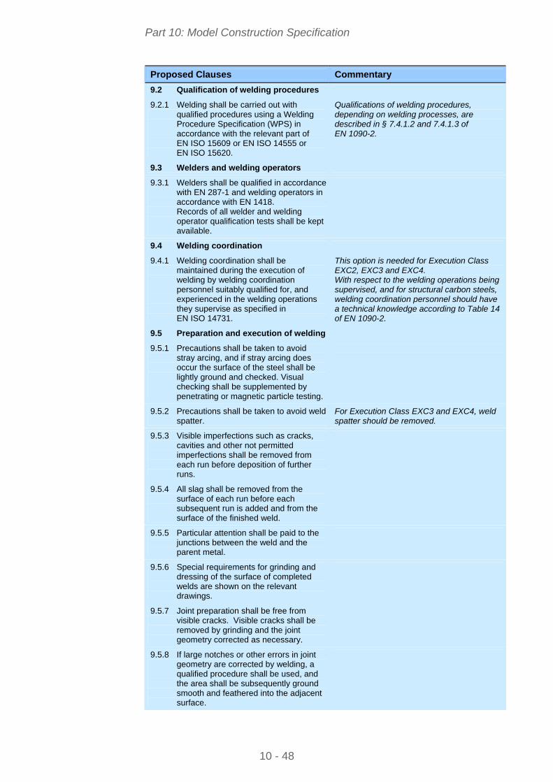
Part 10: Model Construction Specification
10 - 48
Proposed Clauses Commentary
9.2 Qualification of welding procedures
9.2.1 Welding shall be carried out with qualified procedures using a Welding Procedure Specification (WPS) in accordance with the relevant part of EN ISO 15609 or EN ISO 14555 or EN ISO 15620.
Qualifications of welding procedures, depending on welding processes, are described in § 7.4.1.2 and 7.4.1.3 of EN 1090-2.
9.3 Welders and welding operators
9.3.1 Welders shall be qualified in accordance with EN 287-1 and welding operators in accordance with EN 1418. Records of all welder and welding operator qualification tests shall be kept available.
9.4 Welding coordination
9.4.1 Welding coordination shall be maintained during the execution of welding by welding coordination personnel suitably qualified for, and experienced in the welding operations they supervise as specified in EN ISO 14731.
This option is needed for Execution Class EXC2, EXC3 and EXC4. With respect to the welding operations being supervised, and for structural carbon steels, welding coordination personnel should have a technical knowledge according to Table 14 of EN 1090-2.
9.5 Preparation and execution of welding
9.5.1 Precautions shall be taken to avoid stray arcing, and if stray arcing does occur the surface of the steel shall be lightly ground and checked. Visual checking shall be supplemented by penetrating or magnetic particle testing.
9.5.2 Precautions shall be taken to avoid weld spatter.
For Execution Class EXC3 and EXC4, weld spatter should be removed.
9.5.3 Visible imperfections such as cracks, cavities and other not permitted imperfections shall be removed from each run before deposition of further runs.
9.5.4 All slag shall be removed from the surface of each run before each subsequent run is added and from the surface of the finished weld.
9.5.5 Particular attention shall be paid to the junctions between the weld and the parent metal.
9.5.6 Special requirements for grinding and dressing of the surface of completed welds are shown on the relevant drawings.
9.5.7 Joint preparation shall be free from visible cracks. Visible cracks shall be removed by grinding and the joint geometry corrected as necessary.
9.5.8 If large notches or other errors in joint geometry are corrected by welding, a qualified procedure shall be used, and the area shall be subsequently ground smooth and feathered into the adjacent surface.

Part 10: Model Construction Specification
10 - 49
Proposed Clauses Commentary
9.5.9 All surfaces to be welded shall be dry and free from material that would adversely affect the quality of the welds or impede the process of welding.
Such as rust, organic material or galvanizing.
9.5.10 Requirements of § 7.5.1 to 7.5.16 of EN 1090-2 shall be applied as appropriate.
9.6 Acceptance criteria
9.6.1 Welded components shall comply with the requirements specified in § 10 and 11 of EN 1090-2.
9.6.2 The acceptance criteria for weld imperfections shall conform to the requirements of § 7.6 of EN 1090-2.
10. MECHANICAL FASTENING
10.1 General
10.1.1 Minimum nominal fastener diameter, bolt length, length of protrusion, length of the unthreaded bolt shaft and clamp length shall comply with the requirements of § 8.2.2 of EN 1090-2.
10.1.2 Requirements given in § 8.2.3 of EN 1090-2 for washers shall apply.
10.1.3 Tightening of non-preloaded bolts shall comply with the requirements of § 8.3 of EN 1090-2. The bolt shall protrude from the face of the nut, after tightening, not less than one full thread pitch.
10.1.4 Precautions and preparation of contact surfaces in slip resistant connections shall comply with the requirements of § 8.4 and Table 18 of EN 1090-2. Slip factor shall be determined by test as specified in Annex G of EN 1090-2.
10.1.5 Tightening methods of preloaded bolts shall comply with the requirements of § 8.5 of EN 1090-2; special requirements are specified on the relevant documents.
10.2 Bolts
10.2.1 Bolt sizes for structural bolting shall be as specified on the drawings.
10.2.2 Where the structure has been designed to utilise the shear resistance of the unthreaded shank of bolts, this is specified on the drawings and the dimensions of the bolts are given.
The locations and dimensions must be given on the drawings. Reliance on the resistance of the unthreaded shank, rather than the threaded part, is inadvisable because it requires a higher level of control on bolt supply and installation to ensure that only unthreaded parts exist in the part of the connection where the resistance to shear is required.
10.3 Nuts
10.3.1 Nuts shall be assembled so that their designation markings are visible for inspection after assembly.

Part 10: Model Construction Specification
10 - 50
Proposed Clauses Commentary
10.3.2 Nuts shall run freely on their partnering bolt, which is easily checked during hand assembly.
Any nut and bolt assembly where the nut does not run freely should be discarded.
10.4 Washers
10.4.1 Washers shall be provided under the nut or the bolt head of non-preloaded bolts, whichever is to be rotated.
10.4.2 For preloaded bolts : - for 8.8 bolts, a washer shall be used under the bolt head or the nut, whichever is to be rotated; - for 10.9 bolts, washers shall be used under both the bolt head and the nut.
10.5 Preparation of contact surfaces in slip-resistant connections.
10.5.1 The area of contact surfaces in preloaded connections shall be as specified on the drawings. For contact surfaces in slip-resistant connections shown on the relevant drawings, the following particular treatment shall apply: ... (Insert requirements). The treated surfaces shall be adequately protected until they are brought together.
10.5.2 Preparation of contact surfaces in slip-resistant connections shall comply with the requirements of § 8.4 of EN 1090-2; special requirements are specified on the relevant documents.
10.6 Tightening of preloaded bolts
10.6.1 The nominal minimum preloading force Fp,C shall be taken as indicated on the relevant drawings.
Usually, Fp,C = 0,7.fub.As.
10.6.2 The following tightening method(s) shall be used: ... (insert specific tightening methods)
The different tightening methods are described in Table 20 of EN 1090-2.
10.6.3 As an alternative to Table 20 of EN 1090-2, calibration to Annex H of EN 1090-2 may be used: - for all tightening methods; - for all tightening methods, except for the torque method.
(choose one of the above options)
10.6.4 When bolts are tightened by rotation of the bolt head, the following special precautions shall be taken: ... (insert special precautions depending on the tightening method adopted).
10.6.5 For thick surface coatings shown on the relevant drawings, the following measures shall be taken to offset possible subsequent loss of preloading force: ... (insert specific measures, depending on the tightening method adopted).
If torque method is used, this may be by retightening after a delay of some days.

Part 10: Model Construction Specification
10 - 51
Proposed Clauses Commentary
10.6.6 For the combined method, when using the value Mr,1 for the first tightening step, the simplified expression of Mr,1 (in § 8.5.4 of EN 1090-2) may (or may not) be used. (choose one of the above options)
10.6.7 For the combined method, values other than those given in Table 21 of EN 1090-2 shall not be used unless calibrated in accordance with Annex H of EN 1090-2.
10.6.8 For the HRC method, the first tightening step shall be repeated as necessary if the pre-tightening is relaxed by the subsequent tightening of the remainder of the bolts in the connection.
This first step should be completed for all bolts in one connection prior to commencement of the second step. Guidance of the equipment manufacturer may give additional information on how to identify if pre-tightening has occurred, e.g. sound of shear wrench changing, or if other methods of pre-tightening are suitable.
10.7 Fit bolts
10.7.1 Where permitted on the drawings, the length of the threaded portion of the shank of a fit bolt may exceed 1/3 of the thickness of the plate, subject to the following requirements: ... (Insert details)
Insert this clause if such permission is to be given and specify on the drawings for which bolts the longer thread length is permitted.
11. ERECTION
11.1 The design is based on the construction method and/or sequences given in the following documents: (Insert list).
11.2 Requirements for temporary bracing compatible with the construction method and/or sequences are specified on the following drawings: (Insert list)
Insert list of relevant drawings and other documents. Information should include, amongst other things, allowances for permanent deformations (pre-camber), settlement of supports, assumptions for temporary stability and assumptions about propped/un-propped conditions in staged construction. The designer has the duty to ensure that the permanent works can be built safely. The drawings will show a construction method and/or sequences and will show either in detail or indicatively the nature and positions of temporary bracings compatible with those sequences. These temporary bracings will normally be those required to provide stability in the ‘bare steel’ and ‘wet concrete’ conditions. The elements of the temporary bracing would normally be designed by the permanent works designer; if that is not the case, it should be stated in the contract documents (preferably on the drawings) that their design is the constructor’s responsibility.
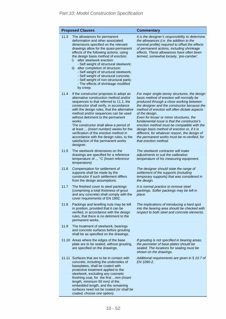
Part 10: Model Construction Specification
10 - 52
Proposed Clauses Commentary
11.3 The allowances for permanent deformation and other associated dimensions specified on the relevant drawings allow for the quasi-permanent effects of the following actions, using the design basis method of erection: i) after steelwork erection: - Self weight of structural steelwork; ii) after completion of structure: - Self weight of structural steelwork; - Self weight of structural concrete; - Self weight of non-structural parts; - The effects of shrinkage modified
by creep.
It is the designer’s responsibility to determine the allowances (i.e. the addition to the nominal profile) required to offset the effects of permanent actions, including shrinkage effects. These allowances have often been termed, somewhat loosely, ‘pre-camber’.
11.4 If the constructor proposes to adopt an alternative construction method and/or sequences to that referred to 11.1, the constructor shall verify, in accordance with the design rules, that the alternative method and/or sequences can be used without detriment to the permanent works. The constructor shall allow a period of at least ... (insert number) weeks for the verification of the erection method in accordance with the design rules, to the satisfaction of the permanent works designer.
For major single-storey structures, the design basis method of erection will normally be produced through a close working between the designer and the constructor because the method of erection will often dictate aspects of the design. Even for lesser or minor structures, the fundamental issue is that the constructor's erection method must be compatible with the design basis method of erection or, if it is different, for whatever reason, the design of the permanent works must be re-verified, for that erection method.
11.5 The steelwork dimensions on the drawings are specified for a reference temperature of ... °C (Insert reference temperature)
The steelwork contractor will make adjustments to suit the calibration temperature of his measuring equipment.
11.6 Compensation for settlement of supports shall be made by the constructor if such settlement differs from the design assumptions.
The designer should state the range of settlement of the supports (including temporary supports) that was considered in the design.
11.7 The finished cover to steel packings (comprising a total thickness of grout and any concrete) shall comply with the cover requirements of EN 1992.
It is normal practice to remove steel packings. Softer packings may be left in place.
11.8 Packings and levelling nuts may be left in position, provided that it can be verified, in accordance with the design rules, that there is no detriment to the permanent works.
The implications of introducing a hard spot into the bearing area should be checked with respect to both steel and concrete elements.
11.9 The treatment of steelwork, bearings and concrete surfaces before grouting shall be as specified on the drawings.
11.10 Areas where the edges of the base plate are to be sealed, without grouting, are specified on the drawings.
If grouting is not specified in bearing areas, the perimeter of base plates should be sealed. The locations for sealing must be shown on the drawings.
11.11 Surfaces that are to be in contact with concrete, including the undersides of baseplates, shall be coated with protective treatment applied to the steelwork, excluding any cosmetic finishing coat, for the first ...mm (insert length, minimum 50 mm) of the embedded length, and the remaining surfaces need not be coated (or shall be coated, choose one option).
Additional requirements are given in § 10.7 of EN 1090-2.