construction specification for civil works c224 open drains
TRANSCRIPT
Tamworth Regional Council Revision 1 (20/05/2019)
Construction Specification for Civil Works
C224 – Open Drains
(including Kerb and Gutter)
CONSTRUCTION SPECIFICATION FOR CIVIL WORKS C224 – OPEN DRAINS (INCLUDING KERB AND GUTTER)
Tamworth Regional Council Page: 1 Revision 1 (20/05/2019)
TABLE OF CONTENTS
CLAUSE CONTENTS PAGE
ORIGIN OF DOCUMENT, COPYRIGHT ....................................................................................................................2
REVISIONS: C224 - OPEN DRAINS, INCLUDING KERB & GUTTER .....................................................................2
GENERAL .................................................................................................................................. 3
C224.01 SCOPE ..............................................................................................................................................3
C224.02 DEFINITION ......................................................................................................................................3
C224.03 REFERENCE DOCUMENTS ...........................................................................................................3
UNLINED OPEN DRAINS ......................................................................................................... 5
C224.04 GENERAL .........................................................................................................................................5
C224.05 TYPES ...............................................................................................................................................5
C224.06 CONSTRUCTION .............................................................................................................................5
LINED OPEN DRAINS ............................................................................................................... 7
C224.07 GENERAL .........................................................................................................................................7
C224.08 CONCRETE LINING .........................................................................................................................7
C224.09 BATTER DRAINS .............................................................................................................................7
C224.10 PROPRIETARY PRODUCTS ..........................................................................................................8
C224.11 KERB AND GUTTER / CHANNEL ...................................................................................................8
ROCK FILLED WIRE MATTRESSES AND GABIONS ..........................................................10
C224.12 GENERAL ...................................................................................................................................... 10
C224.13 MATERIALS ................................................................................................................................... 10
C224.14 ASSEMBLY AND ERECTION ....................................................................................................... 11
LIMITS AND TOLERANCES ...................................................................................................12
C224.15 SUMMARY OF LIMITS AND TOLERANCES ............................................................................... 12
CONSTRUCTION SPECIFICATION FOR CIVIL WORKS C224 – OPEN DRAINS (INCLUDING KERB AND GUTTER)
Tamworth Regional Council Page: 2 Revision 1 (20/05/2019)
ORIGIN OF DOCUMENT, COPYRIGHT
This document was originally based on AUS-SPEC - Development Construction Specification C224 - Open Drains, Including Kerb & Gutter. Substantial parts of the original AUS-SPEC document have been deleted and replaced in the production of this Tamworth Regional Council Specification for Civil Works. The parts of the AUS-SPEC document that remain are still subject to the original copyright.
This document has been developed for use with the construction of civil works within the Tamworth Regional Council local government area.
This is not a controlled document. A full copy of the latest version of this document can be found on the Tamworth Regional Council Internet website: http://www.tamworth.nsw.gov.au/construction_specifications
REVISIONS: C224 - OPEN DRAINS, INCLUDING KERB & GUTTER
REVISIONS CLAUSES AMENDED AMENDMENT DETAILS DATE
1 Original Issue 20/05/2019
CONSTRUCTION SPECIFICATION FOR CIVIL WORKS C224 – OPEN DRAINS (INCLUDING KERB AND GUTTER)
Tamworth Regional Council Page: 3 Revision 1 (20/05/2019)
GENERAL
C224.01 SCOPE
This Specification is for the construction, lining and protection of all types of open drains including the construction of rock filled wire mattresses and gabions.
This Specification should be read in conjunction with C220 - Stormwater Drainage and other drainage Specifications as applicable:
C221- Pipe Drainage.
C222 - Precast Box Culverts.
C223 - Drainage Structures.
Associated Specifications
Requirements for quality control and testing, including maximum lot sizes and minimum test frequencies, are cited in CQC-Quality Control Requirements – Sub-Annexure B2.
Quality
C224.02 DEFINITION
Open drains are all drains other than pipe and box culverts and sub soil and include catch drains, contour drains, diversion drains, table drains, batter drains, swales, channels, gutters and kerbs and gutters.
Open Drains
The Works – Defined as follows:
Developer Infrastructure Works - work includes subdivisions and any public infrastructure work associated with an approved Development in the TRC local government area requiring a construction certificate.
Contracted Works – infrastructure work undertaken by a Principal Contractor or subcontractor formally appointed by TRC and supervised by TRC.
Internal Works - infrastructure work undertaken by TRC’s day labour workforce.
The Works
Constructor – Defined as the organisation responsible for construction of the Works and the Principal Contractor as defined in the Work Health and Safety Act 2011.
Constructor
TRC Representative – Defined as follows:
Developer Infrastructure Works – Nominated TRC officer(s) for the approved Development.
For Contracted Works – the Superintendent.
For Internal Works – TRC Asset Owner
TRC Representative
Constructor’s Representative – Defined as follows:
Contracted Works – the Principal Contractor’s nominated representative as per the relevant contract.
Internal Works – TRC officer responsible for delivery.
Constructor’s Representative
Developer’s Representative– Defined as the person or organisation appointed by the
Developer to administer the Constructor responsible for the delivery of Developer
Infrastructure Works.
Developer’s Representative
C224.03 REFERENCE DOCUMENTS
Documents referenced in this Specification are listed in full below whilst being cited in the text in the abbreviated form or code indicated.
Documents Standards Test Methods
CONSTRUCTION SPECIFICATION FOR CIVIL WORKS C224 – OPEN DRAINS (INCLUDING KERB AND GUTTER)
Tamworth Regional Council Page: 4 Revision 1 (20/05/2019)
Where not otherwise specified in the relevant Tamworth Regional Council (TRC) Construction Specifications or the approved design drawings, the Constructor shall use the latest versions of the Reference documentation, including amendments and supplements, listed in the TRC Construction Specifications at the time of the Works approval.
Currency
(a) Tamworth Regional Council (TRC) Specifications
C211- Control of Erosion and Sedimentation.
C220 - Stormwater Drainage.
C221 - Pipe Drainage.
C222 - Precast Box Culverts.
C271 - Minor Concrete Works.
C273 – Landscaping.
CQC - Quality Control Requirements
(b) Australian Standards
References in this Specification or on the approved design drawings to Australian Standards are noted by their prefix AS or AS/NZS.
AS 1141.22 - Wet/dry strength variation.
AS 1289.5.4.1 - Compaction control test - Dry density ratio, moisture variation and moisture ratio.
AS 2758.4 - Aggregate for gabion baskets and wire mattresses.
AS 2876 - Concrete kerbs and channels (gutters) - Manually or machine placed.
AS/NZS 4534 - Zinc and zinc/aluminium-alloy coatings on steel wire.
(c) Austroads Publications
AUSTROADS - Guide to Pavement Technology Part 4G: Geotextiles and Geogrids.
AUSTROADS - Guide to Road Design Part 5: Drainage – General and Hydrology Conssiderations.
(d) TRC Standard Drawings Applicable to this Section
RD003 - Kerb Profiles.
RD004 - Kerb Ramps.
RD008 - Driveways – Urban Residential.
RD009 - Driveways – Industrial.
RD010 - Driveways – Rural Access Across Table Drain
TRC Standard Drawings shall take precedence over ALL other drawings related to the Works.
Where any TRC Standard Drawings conflicts with this Specification, the requirements of this Specification shall take precedence. Proposals to deviate from this Specification shall
constitute a HOLD POINT.
HOLD POINT
All proposed deviations from the approved design drawings, TRC Standard Drawings, this Specification or the documents referenced within it, shall be submitted for approval to the TRC Representative with supporting evidence at least five (5) working days prior to the work being undertaken.
PROCESS HELD: The lot or element affected by the proposed deviation.
Hold Point
CONSTRUCTION SPECIFICATION FOR CIVIL WORKS C224 – OPEN DRAINS (INCLUDING KERB AND GUTTER)
Tamworth Regional Council Page: 5 Revision 1 (20/05/2019)
UNLINED OPEN DRAINS
C224.04 GENERAL
Unless shown otherwise on the approved design drawings, drains shall be of trapezoidal cross section and shall not be less than 300mm deep.
Shape
Open drains shall be graded to ensure free flow of water and, shall not have a grade of less than 1%.
Grade
Where trees marked for preservation or rock outcrops occur in the line of a drain, the drain may be diverted subject to approval by the TRC Representative.
Trees and Rock Outcrops
Open drains shall be extended as necessary to lead the water clear of the work to natural drainage depressions, culverts, or pits connected to underground drainage systems. The drains shall follow existing watercourses and depressions in the natural surface, unless other locations are shown on the approved design drawings.
Open Drains
All work shall be undertaken in accordance with the requirements of C211 - Control of Erosion and Sedimentation.
Control of Erosion
C224.05 TYPES
Catch drains shall be provided above the tops of cuttings or the toes of embankments where shown on the approved design drawings before construction of the adjacent roadway. The edges of catch-drains shall not be positioned less than 2m from the tops of cuttings or the toes of embankments nor more than is necessary to maintain the fall of the drains.
Catch Drains
Minor diversion and contour drains shall be constructed where shown on the approved design drawings. Minor diversion drains shall have the same capacity as the nearest pipe culvert on the line of the drain.
Diversion & Contour Drains
Table drains, swales and depressed medians shall be constructed to the line and level shown or calculated from the approved design drawings.
Table Drains
Inlet, outlet and diversion channels shall be excavated as shown on the approved design drawings and shall extend to join the existing stream bed in a regular manner, avoiding disturbance in stream flow. The channel shall be excavated to the full width of the structure but the existing stream bed shall be preserved as far as possible outside the limits of the excavation.
Channels
C224.06 CONSTRUCTION
Material excavated from drains shall be placed on the lower sides of the drains and formed as banks with slopes not steeper than 4H:1V on the cross section of the bank to increase the capacity of the drains. This material shall be compacted in accordance with AS 1289.5.4.1 and shall be not less than 95% for standard compactive effort or equivalent modified compactive effort. Excavated materials not placed will be spoiled in accordance with C213 - Earthworks.
Excavated Material
The Constructor shall ensure that none of the activities associated with the work disturbs any watercourse outside the site through the suitable implementation of erosion and sedimentation control measures in accordance with C211 – Control of Erosion and Sedimentation. Any excavation below the level of the natural channel shall be backfilled with suitable material compacted to a density equal to and compatible with that existing naturally.
Constructor's Responsibility
Any excess material shall be legally and responsibly disposed of by the Constructor. Excess Material
Unlined drains and areas adjacent to open drains shall be revegetated immediately after the drains are complete, in accordance with the approved design drawings. A suitable allowance shall be allowed downstream of open drains for the placement of surface
Revegetation
CONSTRUCTION SPECIFICATION FOR CIVIL WORKS C224 – OPEN DRAINS (INCLUDING KERB AND GUTTER)
Tamworth Regional Council Page: 6 Revision 1 (20/05/2019)
treatments such as turf or rip rap.
Deviations from the design position or cross section of the open drain shall be proposed to the TRC Representative for approval. The suitability of the revised location shall be validated by the Designer. Verification of the conformance of unlined drains shall be undertaken in accordance with C213 -Earthworks.
Revised Position
HOLD POINT
Deviations from the design position shall be submitted to the TRC Representative at least three (3) working days prior to constructing the affected lot.
Supporting information shall be submitted detailing the revised position and the reasons for the deviation.
PROCESS HELD: Construction of the open drain.
Hold Point
CONSTRUCTION SPECIFICATION FOR CIVIL WORKS C224 – OPEN DRAINS (INCLUDING KERB AND GUTTER)
Tamworth Regional Council Page: 7 Revision 1 (20/05/2019)
LINED OPEN DRAINS
C224.07 GENERAL
Lined open drains shall be formed as for unlined open drains with the inclusion of a lined invert in accordance with the approved design drawings.
Shape
Lining shall conform to the profile of the drain and shall be provided as soon as possible after forming the drain.
Profile
Before placing any lining material, the foundation material shall be shaped and compacted to form a firm base for the lining. Other than for kerb and gutter constructed on pavement courses, the relative compaction, as determined by AS 1289 5.4.1 shall not be less than 98% for standard compactive effort.
Compaction of Foundations
C224.08 CONCRETE LINING
Concrete lining for open drains shall be cast-in-situ or sprayed concrete supplied and placed in accordance with C271 - Minor Concrete Works. Weepholes shall be provided in the concrete channels greater than 0.5m in height at intervals of 2m.
Method
Contraction joints in concrete lining, consisting of narrow transverse and vertical grooves, 20mm deep, shall be formed neatly in the surface of the freshly placed concrete at intervals of 3m unless specified otherwise in the approved design drawings. Expansion joints shall be placed at intervals shown in the approved design drawings, but not more than 15m. Expansion Joints shall consist of a preformed jointing material of bituminous fibreboard and shall be of sufficient depth to fill the joint.
Jointing
A concrete mix design, complying with C271 - Minor Concrete Works shall be submitted for approval to the TRC Representative and/or the Developer’s Representative (for Developer Infrastructure Works) along with other verification records for reinforcement details where applicable.
Concrete Mix Design
HOLD POINT
Prior to the placement of concrete, records demonstrating conformance of the foundation, accompanied by a concrete mix design, shall be submitted by the Constructor to the TRC Representative and/or the Developer’s Representative (for Developer Infrastructure Works) for approval at least three (3) working days prior to pouring the concrete lined drain.
PROCESS HELD: Delivery and placement of insitu concrete.
Hold Point
C224.09 BATTER DRAINS
Batter drains shall be constructed using precast nestable concrete units or as detailed on the approved design drawings.
Type
The units shall be installed in carefully excavated and template controlled trench to produce an even rim line of +0mm to –50mm from the batter line at the underside of topsoil.
Installation
Any over excavation and undulations in the batter line shall be backfilled and both sides of the drain compacted over the full length to form a firm shoulder against the rim of the batter drain.
Compaction
When topsoil is placed it shall be tapered over a width of 1m to zero thickness at the rim of the drain. Both sides of the drain shall then be turfed for minimum width of 600mm and pinned down as provided in C273 - Landscaping.
Topsoil and Turfing
CONSTRUCTION SPECIFICATION FOR CIVIL WORKS C224 – OPEN DRAINS (INCLUDING KERB AND GUTTER)
Tamworth Regional Council Page: 8 Revision 1 (20/05/2019)
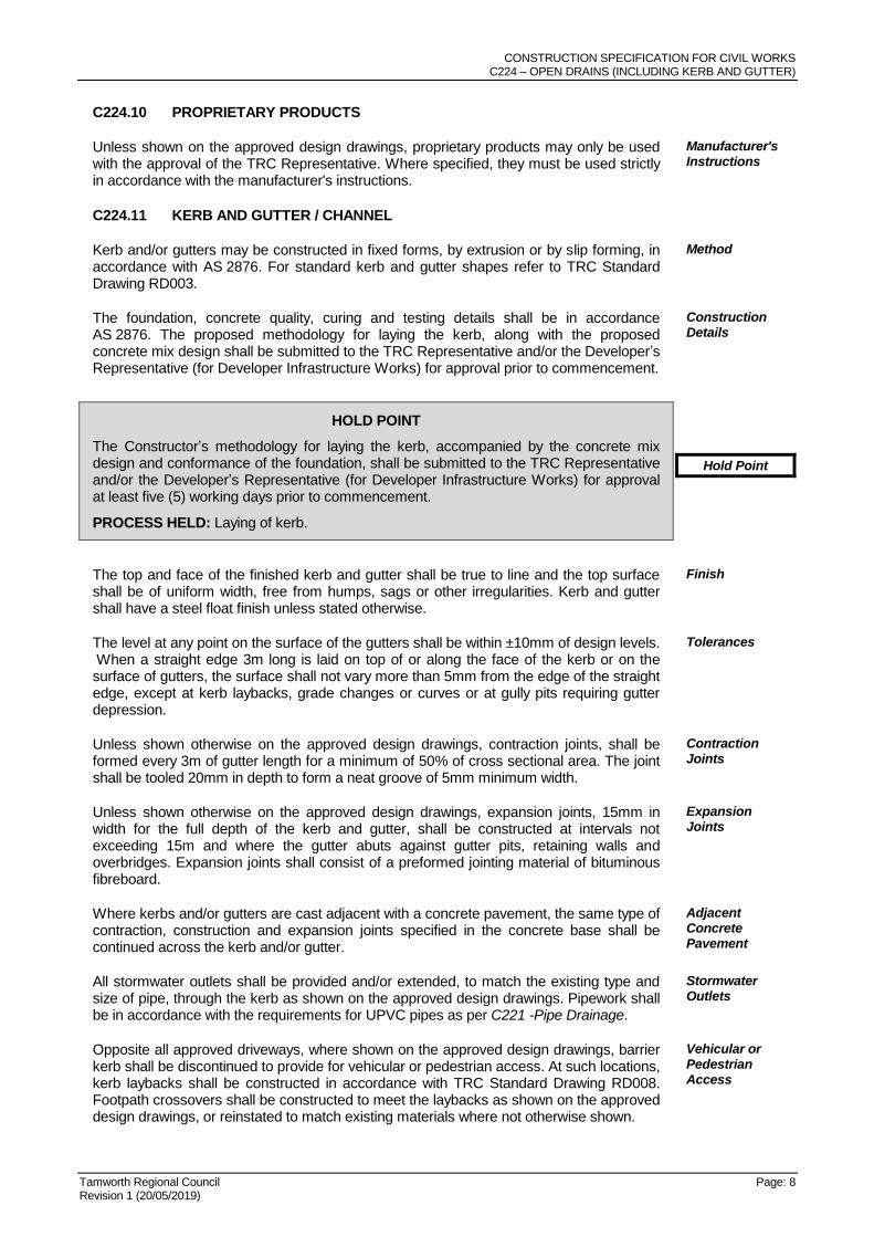
C224.10 PROPRIETARY PRODUCTS
Unless shown on the approved design drawings, proprietary products may only be used with the approval of the TRC Representative. Where specified, they must be used strictly in accordance with the manufacturer's instructions.
Manufacturer's Instructions
C224.11 KERB AND GUTTER / CHANNEL
Kerb and/or gutters may be constructed in fixed forms, by extrusion or by slip forming, in accordance with AS 2876. For standard kerb and gutter shapes refer to TRC Standard Drawing RD003.
Method
The foundation, concrete quality, curing and testing details shall be in accordance AS 2876. The proposed methodology for laying the kerb, along with the proposed concrete mix design shall be submitted to the TRC Representative and/or the Developer’s Representative (for Developer Infrastructure Works) for approval prior to commencement.
Construction Details
HOLD POINT
The Constructor’s methodology for laying the kerb, accompanied by the concrete mix design and conformance of the foundation, shall be submitted to the TRC Representative and/or the Developer’s Representative (for Developer Infrastructure Works) for approval at least five (5) working days prior to commencement.
PROCESS HELD: Laying of kerb.
Hold Point
The top and face of the finished kerb and gutter shall be true to line and the top surface shall be of uniform width, free from humps, sags or other irregularities. Kerb and gutter shall have a steel float finish unless stated otherwise.
Finish
The level at any point on the surface of the gutters shall be within ±10mm of design levels. When a straight edge 3m long is laid on top of or along the face of the kerb or on the surface of gutters, the surface shall not vary more than 5mm from the edge of the straight edge, except at kerb laybacks, grade changes or curves or at gully pits requiring gutter depression.
Tolerances
Unless shown otherwise on the approved design drawings, contraction joints, shall be formed every 3m of gutter length for a minimum of 50% of cross sectional area. The joint shall be tooled 20mm in depth to form a neat groove of 5mm minimum width.
Contraction Joints
Unless shown otherwise on the approved design drawings, expansion joints, 15mm in width for the full depth of the kerb and gutter, shall be constructed at intervals not exceeding 15m and where the gutter abuts against gutter pits, retaining walls and overbridges. Expansion joints shall consist of a preformed jointing material of bituminous fibreboard.
Expansion Joints
Where kerbs and/or gutters are cast adjacent with a concrete pavement, the same type of contraction, construction and expansion joints specified in the concrete base shall be continued across the kerb and/or gutter.
Adjacent Concrete Pavement
All stormwater outlets shall be provided and/or extended, to match the existing type and size of pipe, through the kerb as shown on the approved design drawings. Pipework shall be in accordance with the requirements for UPVC pipes as per C221 -Pipe Drainage.
Stormwater Outlets
Opposite all approved driveways, where shown on the approved design drawings, barrier kerb shall be discontinued to provide for vehicular or pedestrian access. At such locations, kerb laybacks shall be constructed in accordance with TRC Standard Drawing RD008. Footpath crossovers shall be constructed to meet the laybacks as shown on the approved design drawings, or reinstated to match existing materials where not otherwise shown.
Vehicular or Pedestrian Access

CONSTRUCTION SPECIFICATION FOR CIVIL WORKS C224 – OPEN DRAINS (INCLUDING KERB AND GUTTER)
Tamworth Regional Council Page: 9 Revision 1 (20/05/2019)
Kerb ramps shall be installed in accordance with TRC Standard Drawing RD004. Ker Ramps
After the new kerb and gutter has been constructed and not earlier than three (3) days after placing, the spaces on both sides of the kerb and/or gutters shall be backfilled and reinstated in accordance with the approved design drawings.
Backfill Timing
Backfill material behind the kerb shall consist of granular material, free of organic material, clay and rock in excess of 50mm in diameter.
Backfill Material
Backfill material behind the kerb shall be compacted in layers not greater than 150mm thick, to a relative compaction of 95% when tested in accordance with AS 1289.5.4.1, for standard compactive effort. The whole of the work shall be finished in a neat and workmanlike manner, free draining and free from surface undulations and trip hazards.
Behind Kerb
Pavement material adjacent to the new gutter shall be placed in accordance with the approved design drawings.
Pavement
CONSTRUCTION SPECIFICATION FOR CIVIL WORKS C224 – OPEN DRAINS (INCLUDING KERB AND GUTTER)
Tamworth Regional Council Page: 10 Revision 1 (20/05/2019)
ROCK FILLED WIRE MATTRESSES AND GABIONS
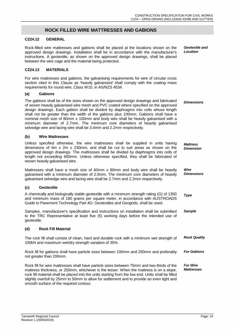
C224.12 GENERAL
Rock-filled wire mattresses and gabions shall be placed at the locations shown on the approved design drawings. Installation shall be in accordance with the manufacturer's instructions. A geotextile, as shown on the approved design drawings, shall be placed between the wire cage and the material being protected.
Geotextile and Location
C224.13 MATERIALS
For wire mattresses and gabions, the galvanising requirements for wire of circular cross section cited in this Clause as 'heavily galvanised' shall comply with the coating mass requirements for round wire, Class W10, in AS/NZS 4534.
(a) Gabions
The gabions shall be of the sizes shown on the approved design drawings and fabricated of woven heavily galvanised wire mesh and PVC coated where specified on the approved design drawings. Each gabion shall be divided by diaphragms into cells whose length shall not be greater than the width of the gabions plus 100mm. Gabions shall have a nominal mesh size of 80mm x 100mm and body wire shall be heavily galvanised with a minimum diameter of 2.7mm. The minimum core diameters of heavily galvanised selvedge wire and lacing wire shall be 3.4mm and 2.2mm respectively.
Dimensions
(b) Wire Mattresses
Unless specified otherwise, the wire mattresses shall be supplied in units having dimensions of 6m x 2m x 230mm, and shall be cut to suit areas as shown on the approved design drawings. The mattresses shall be divided by diaphragms into cells of length not exceeding 600mm. Unless otherwise specified, they shall be fabricated of woven heavily galvanised wire.
Mattress Dimension
Mattresses shall have a mesh size of 60mm x 80mm and body wire shall be heavily galvanised with a minimum diameter of 2.0mm. The minimum core diameters of heavily galvanised selvedge wire and lacing wire shall be 2.7mm and 2.2mm respectively.
Wire Dimensions
(c) Geotextile
A chemically and biologically stable geotextile with a minimum strength rating (G) of 1350 and minimum mass of 180 grams per square meter, in accordance with AUSTROADS Guide to Pavement Technology Part 4G: Geotextiles and Geogrids, shall be used.
Type
Samples, manufacturer's specification and instructions on installation shall be submitted to the TRC Representative at least five (5) working days before the intended use of geotextile.
Sample
(d) Rock Fill Material
The rock fill shall consist of clean, hard and durable rock with a minimum wet strength of 100kN and maximum wet/dry strength variation of 35%.
Rock Quality
Rock fill for gabions shall have particle sizes between 100mm and 250mm and preferably not greater than 200mm.
For Gabions
Rock fill for wire mattresses shall have particle sizes between 75mm and two-thirds of the mattress thickness, or 250mm, whichever is the lesser. When the mattress is on a slope, rock fill material shall be placed into the units starting from the low end. Units shall be filled slightly overfull by 25mm to 50mm to allow for settlement and to provide an even tight and smooth surface of the required contour.
For Wire Mattresses
CONSTRUCTION SPECIFICATION FOR CIVIL WORKS C224 – OPEN DRAINS (INCLUDING KERB AND GUTTER)
Tamworth Regional Council Page: 11 Revision 1 (20/05/2019)
HOLD POINT
The methodology for the construction of gabions or rock mattresses, accompanied by evidence that the gabions baskets or wire mattress, the rock and geotextile meets the specified requirements, shall be submitted for approval to the TRC Representative and/or the Developer’s Representative (for Developer Infrastructure Works) at least five (5) working days prior to commencement. Conformance of the respective foundations shall also be provided.
PROCESS HELD: Commencement of construction of gabion and rock mattresses.
Hold Point
C224.14 ASSEMBLY AND ERECTION
Before laying out the gabions or wire mattresses, geotextile shall be placed on the founding material. Preparation of the founding material shall be in accordance with the approved design drawings. The edges of wire mattresses shall be firmly tied to galvanised star pickets driven a minimum of 900mm into the surrounding ground at 1m maximum intervals and the star pickets cut off level with the top of the mattress. The upstream edge of wire mattresses shall be folded down into a trench of minimum depth 300mm and filled with rock fill. This edge shall be tied to star pickets.
Placement of rock fill material shall be by hand or suitable mechanical device to ensure fill is tightly packed with a minimum of voids. The front face, and all other faces that will remain visible shall be packed in a manner which provides a neat face free from excessive bulges, depressions or voids. Where rock is placed using mechanical devices care shall be taken to avoid damage to either the basket, mattress and associated wire coatings. The rock fill shall be levelled off 25mm to 50mm above the top of the mesh to allow for settlement.
Procedure
CONSTRUCTION SPECIFICATION FOR CIVIL WORKS C224 – OPEN DRAINS (INCLUDING KERB AND GUTTER)
Tamworth Regional Council Page: 12 Revision 1 (20/05/2019)
LIMITS AND TOLERANCES
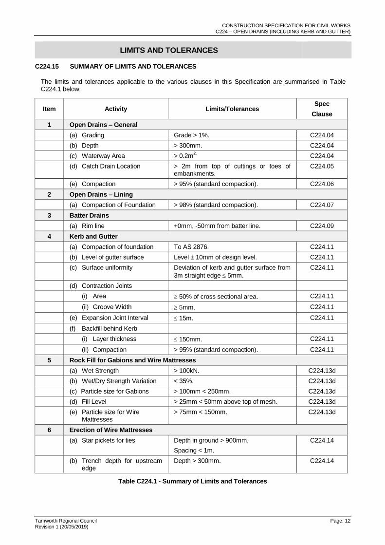
C224.15 SUMMARY OF LIMITS AND TOLERANCES
The limits and tolerances applicable to the various clauses in this Specification are summarised in Table C224.1 below.
Item Activity Limits/Tolerances Spec
Clause
1 Open Drains – General
(a) Grading Grade > 1%. C224.04
(b) Depth > 300mm. C224.04
(c) Waterway Area > 0.2m2. C224.04
(d) Catch Drain Location > 2m from top of cuttings or toes of embankments.
C224.05
(e) Compaction > 95% (standard compaction). C224.06
2 Open Drains – Lining
(a) Compaction of Foundation > 98% (standard compaction). C224.07
3 Batter Drains
(a) Rim line +0mm, -50mm from batter line. C224.09
4 Kerb and Gutter
(a) Compaction of foundation To AS 2876. C224.11
(b) Level of gutter surface Level ± 10mm of design level. C224.11
(c) Surface uniformity Deviation of kerb and gutter surface from
3m straight edge 5mm.
C224.11
(d) Contraction Joints
(i) Area 50% of cross sectional area. C224.11
(ii) Groove Width 5mm. C224.11
(e) Expansion Joint Interval 15m. C224.11
(f) Backfill behind Kerb
(i) Layer thickness 150mm. C224.11
(ii) Compaction > 95% (standard compaction). C224.11
5 Rock Fill for Gabions and Wire Mattresses
(a) Wet Strength > 100kN. C224.13d
(b) Wet/Dry Strength Variation < 35%. C224.13d
(c) Particle size for Gabions > 100mm < 250mm. C224.13d
(d) Fill Level > 25mm < 50mm above top of mesh. C224.13d
(e) Particle size for Wire Mattresses
> 75mm < 150mm. C224.13d
6 Erection of Wire Mattresses
(a) Star pickets for ties Depth in ground > 900mm.
Spacing < 1m.
C224.14
(b) Trench depth for upstream edge
Depth > 300mm. C224.14
Table C224.1 - Summary of Limits and Tolerances
CONSTRUCTION SPECIFICATION FOR CIVIL WORKS C224 – OPEN DRAINS (INCLUDING KERB AND GUTTER)
Tamworth Regional Council Page: 13 Revision 1 (20/05/2019)
This is the last page of the document