technical manual printed precision source model …
TRANSCRIPT
03-TM-0050 REV A Page 1 of 6
DUKANE SEACOM, INC. SARASOTA, FLORIDA 34243 PHONE: 941-741-3200 FAX: 941-739-3201
DOCUMENT NO. 03-TM-0050 © DUKANE SEACOM, INC.
INTERNET: www.radiantpowercorp.com
NOVEMBER 23, 2015
REV A
TECHNICAL MANUAL PRECISION SOURCE
MODEL CT200
UNCONTROLLED W
HEN PRIN
TED
To buy, sell, rent or trade-in this product please click on the link below:http://www.avionteq.com/Dukane-Avionics-CT-200-Calibration-Kit-for-TS-200.aspx
www.avionteq.com
03-TM-0050 REV A Page 2 of 6
This manual should be read in its entirety prior to operation of the CT200 Precision Source
UNCONTROLLED W
HEN PRIN
TED
03-TM-0050 REV A Page 3 of 6
SECTION I
GENERAL INFORMATION
1.1. INTRODUCTION
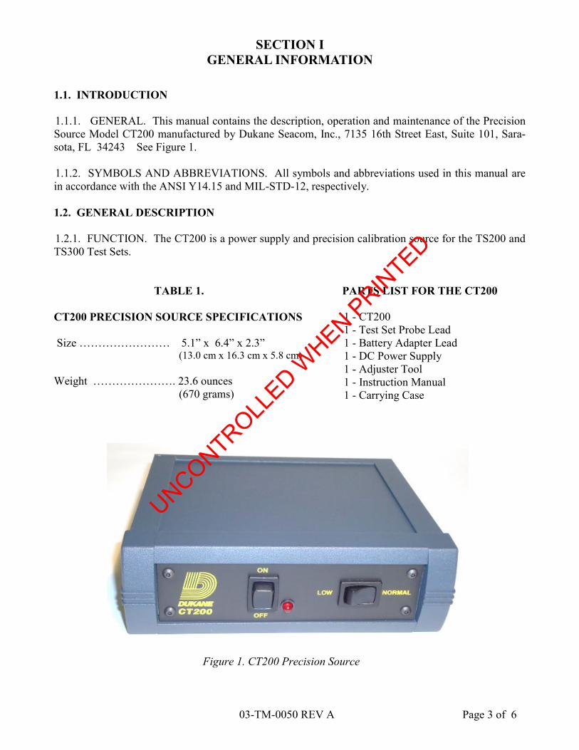
1.1.1. GENERAL. This manual contains the description, operation and maintenance of the Precision
Source Model CT200 manufactured by Dukane Seacom, Inc., 7135 16th Street East, Suite 101, Sara-
sota, FL 34243 See Figure 1.
1.1.2. SYMBOLS AND ABBREVIATIONS. All symbols and abbreviations used in this manual are
in accordance with the ANSI Y14.15 and MIL-STD-12, respectively.
1.2. GENERAL DESCRIPTION
1.2.1. FUNCTION. The CT200 is a power supply and precision calibration source for the TS200 and
TS300 Test Sets.
TABLE 1.
CT200 PRECISION SOURCE SPECIFICATIONS
Size …………………… 5.1” x 6.4” x 2.3” (13.0 cm x 16.3 cm x 5.8 cm)
Weight …………………. 23.6 ounces
(670 grams)
PARTS LIST FOR THE CT200
1 - CT200
1 - Test Set Probe Lead
1 - Battery Adapter Lead
1 - DC Power Supply
1 - Adjuster Tool
1 - Instruction Manual
1 - Carrying Case
Figure 1. CT200 Precision Source
UNCONTROLLED W
HEN PRIN
TED
03-TM-0050 REV A Page 4 of 6
2.1 OPERATION
2.1.1. CT200 SETUP
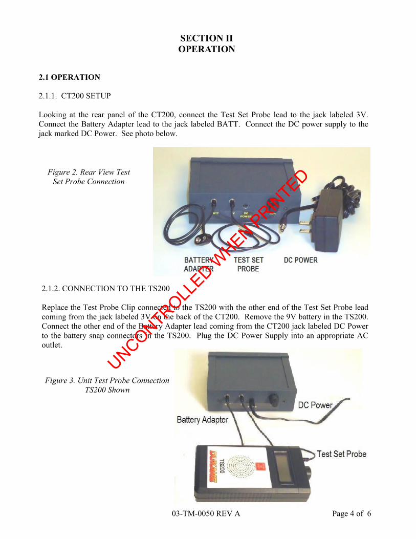
Looking at the rear panel of the CT200, connect the Test Set Probe lead to the jack labeled 3V.
Connect the Battery Adapter lead to the jack labeled BATT. Connect the DC power supply to the
jack marked DC Power. See photo below.
SECTION II
OPERATION
2.1.2. CONNECTION TO THE TS200
Replace the Test Probe Clip connected to the TS200 with the other end of the Test Set Probe lead
coming from the jack labeled 3V on the back of the CT200. Remove the 9V battery in the TS200.
Connect the other end of the Battery Adapter lead coming from the CT200 jack labeled DC Power
to the battery snap connectors in the TS200. Plug the DC Power Supply into an appropriate AC
outlet.
Figure 3. Unit Test Probe Connection
TS200 Shown
Figure 2. Rear View Test
Set Probe Connection
UNCONTROLLED W
HEN PRIN
TED

03-TM-0050 REV A Page 5 of 6
SECTION III
TS200 CALIBRATION PROCEDURE
3.1.4. Adjust the calibration test potentiometer with the Adjuster Tool until the TS200 display reads
3.00V. Reassemble the TS200 housing and attach an approved calibration label. This completes the
calibration.
3.1.5. The CT200 requires calibration every 2 years and 3 months. When calibration is required the
CT200 must be returned to Dukane Seacom,
Inc..
Ship to : Dukane Seacom, Inc.
7135 16th Street East, Suite 101
Sarasota, FL 34243
3.1 CALIBRATION
3.1.1. Low battery indication
Connect test leads from CT200 to the TS200 under test (see Section II). Turn on the power using the
rocker switch on front of CT200 labeled ON/OFF. Set rocker switch labeled LOW/NORMAL to the
“LOW” position. Turn on the TS200 and observe the display. There should be an “LB” (low battery)
indication on the left side of the display. Switch the LOW/NORMAL switch to the “NORMAL” posi-
tion, and observe the display. The “LB” indication will no longer be visible on the display. If either
of these conditions is not met, return the TS200 to Dukane Seacom, Inc. for service.
3.1.2. Calibration of the TS200 Volt Meter
Connect test leads from CT200 to the TS200 under test, (see Section II). Turn on the power to the
CT200. Set the LOW/NORMAL rocker switch to the “NORMAL” position. Turn on the TS200 and
observe the display. The TS200 should display 3.00V. If 3.00V is not displayed turn off power to the
TS200 and the CT200.
3.1.3. Remove the four screws from the back of the TS200; this will expose the calibration test poten-
tiometer (see figure below).
CAUTION
Observe precautions for handling
electrostatic sensitive devices. Wear
a wrist strap and touch ground to
discharge any static before handling.
Figure 4. Calibration Potentiometer
Location TS200 Shown
UNCONTROLLED W
HEN PRIN
TED
03-TM-0050 REV A Page 6 of 6
SECTION IV
WARRANTY
Dukane Seacom, Inc. warrants that the Test Set (referred to as the unit) will be free from defects in
materials and workmanship, when used under normal operating conditions as determined solely by
Dukane Seacom, Inc., for a period of one (1) year from the date of shipment from Dukane Seacom,
Inc..
As the sole remedy for breach of the foregoing warranty, Dukane Seacom, Inc. shall repair or re-
place, at Dukane Seacom, Inc.’s option, any unit, component or part thereof found defective or non-
conforming within said one (1) year period from the date of shipment. Customer shall give Dukane
Seacom, Inc. notice of any defect or nonconformity and, if so instructed by Dukane Seacom, Inc.,
customer shall, at its expense, ship the unit, component or part to Dukane Seacom, Inc.. If Dukane
Seacom, Inc. determines that the unit, component or part is actually defective or nonconforming, it
shall, at its expense, ship a new or a rebuilt unit, component or part to the customer. The customer
shall be responsible to perform, at its own expense, any necessary installation work related to any
defective or nonworking unit, component or part. The functionality and operational aspects of the
unit is determined by the unit operating within the specifications and is dependent of proper mainte-
nance as required to be performed by the customer.
Dukane Seacom, Inc. shall not be liable for any expense or damages resulting from interruptions in
the operation of the unit.
Dukane Seacom, Inc. shall not be liable for the cost of any repairs undertaken by the customer or
any third party without Dukane Seacom, Inc. prior written authorization.
Dukane Seacom, Inc. shall not be liable for any incidental, special consequential or exemplary dam-
ages arising out of the installation, use, testing, servicing or maintenance of any unit, component or
part. This warranty is given in lieu of all other warranties, express or implied, included the warran-
ties of merchantability or fitness for a particular purpose.
Dukane Seacom, Inc.’s total liability under this warranty is limited to the remanufacture or replace-
ment of the unit, component or part.
UNCONTROLLED W
HEN PRIN
TED