tdr o.m. 09-08
DESCRIPTION
PLEASE READ AND UNDERSTAND THE CONTENTS OF THIS MANUAL BEFORE OPERATING THE EQUIPMENT. 600 East Wayne Street Celina, Ohio 45822 Phone: 419-586-7727 Fax: 419-586-9724 Railgates By THIEMAN ! TT AA II LL GGAA TT EESS ,,II NN CC .. NATIONAL TRUCK EQUIPMENT ASSOCIATIONTRANSCRIPT

TDR SSEERRIIEESSRailgates By THIEMAN
TDR-44, 55, 66OWNERS MANUAL/PARTS LIST
IMPORTANT! KEEP IN VEHICLE!!PLEASE READ AND UNDERSTAND THE CONTENTS OF THIS
MANUAL BEFORE OPERATING THE EQUIPMENT.
TTAA IILLGGAA TTEESS,,��IINNCC..600 East Wayne Street
Celina, Ohio 45822Phone: 419-586-7727 Fax: 419-586-9724
NATIONAL TRUCK EQUIPMENT ASSOCIATION

TABLE OF CONTENTSPAGE
WARNINGS .........................................................................................3OPERATING INSTRUCTIONS ............................................................4MAINTENANCE GUIDE ......................................................................5SEMI-ANNUAL INSPECTION..............................................................6OPENING/CLOSING SPEED ADJUSTMENT .....................................7PARTS ORDERING PROCEDURE .....................................................7FRAME ASSEMBLY ......................................................................8 & 9SLIDER ASSEMBLY .................................................................10 & 11PLATFORM ASSEMBLY 62" & 74" DEEP.................................12 & 13PLATFORM ASSEMBLY 86" DEEP ..........................................14 & 15PUMP AND CYLINDER ASSEMBLY.........................................16 & 17PD PUMP & CYLINDER ASSEMBLY........................................18 & 19HARNESS ASSEMBLIES ..................................................................20PUMP ENCLOSURE ASSEMBLY-TOGGLE CONTROL ...................21INSPECTION AND LOCATION OF DECALS ....................................22ELECTRICAL SCHEMATICS.............................................................23ELECTRICAL PICTORIALS...............................................................24HYDRAULIC SCHEMATICS......................................................25 & 26TROUBLE SHOOTING GUIDE - GRAVITY DOWN .....................27-29TAILLIGHT PICTORIAL .....................................................................30
FOR YOUR RECORDSModel No. __________________________ Date Purchased _______________________
Serial No._________________________________________________________________NOTE: When Ordering Parts Be Sure To Include This Information!
Your Thieman Tailgate is constructed of top quality material and is warranted to be freefrom defects in material and workmanship under normal use. With routine maintenance andproper operation this liftgate will provide long lasting service and dependability.
3.
WARNING!
THE FOLLOWING LIST OF WARNINGS ARE TO BE READ BEFORE OPERATING THE TDRSERIES LIFTGATE:
+ Read this Ownerʼs Manual and all of the decals before operating the liftgate.+ All protective covers and guards must be in place before operating the liftgate.+ DO NOT operate the liftgate if you do not have a thorough understanding of the operation
of the liftgate. + NEVER OVERLOAD THE LIFTGATE! The maximum rated capacity of the TDR series dif-
fers with each model as follows:TDR 44 - 4400 lbsTDR 55 - 5500 lbsTDR 66 - 6600 lbs
+ Never use the liftgate if it makes any unusual noises, has vibrations, or fails to operatefreely.
+ Make certain that the area below the platform is clear before and at all times during theoperation of the liftgate.
+ Keep hands and feet clear of all pinch points.+ The platform must be in the closed position and lowered onto the stow latches before tran-
sit.+ Always load as close to the center of the platform and as close to the truck as possible.
See Figure 1.+ Never operate lift trucks on or over any part of the platform.+ Load and unload the platform from the rear and not from the side of the platform. Never
remove the platform support chains to load or unload.+ Only operate liftgate when vehicle is on level ground and parking brake is set.+ Follow the maintenance guide as outlined in this manual.+ DO NOT attempt any repairs unless you are a qualified and authorized THIEMAN distribu-
tor.+ If any repairs, adjustments, or maintenance not covered in this manual are required, con-
tact your nearest Thieman distributor or the factory.+ DO NOT ride the liftgate, it is not intended as a personnel lift.+ This liftgate is intended for the use of loading and unloading cargo only, and is not to be
used for anything other than this.+ DO NOT modify or alter the function of this liftgate. Altering this liftgate may cause serious
personal injury or damage the liftgate and will void all warranties.+ Dock loading bed heights for a 62" deep platform is 40 to 60 inches. Dock loading bed
heights for the 74" and 86" deep platforms are 45 to 60 inches.+ DO NOT fold or unfold the platform unless the liftgate is in the fully raised position or dam-
age to the liftgate may occur.+ DO NOT fold or unfold the platform with a load on the platform.
4.
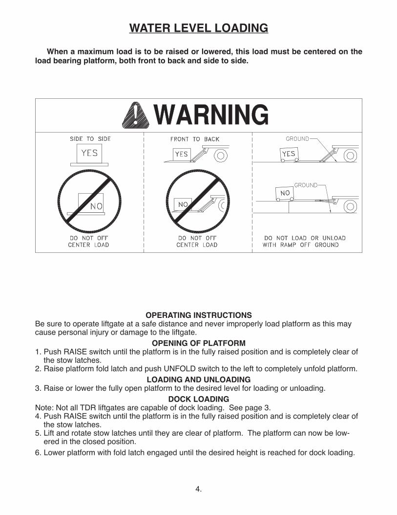
WATER LEVEL LOADINGWhen a maximum load is to be raised or lowered, this load must be centered on the
load bearing platform, both front to back and side to side.
OPERATING INSTRUCTIONSBe sure to operate liftgate at a safe distance and never improperly load platform as this maycause personal injury or damage to the liftgate.
OPENING OF PLATFORM1. Push RAISE switch until the platform is in the fully raised position and is completely clear of
the stow latches.2. Raise platform fold latch and push UNFOLD switch to the left to completely unfold platform.
LOADING AND UNLOADING3. Raise or lower the fully open platform to the desired level for loading or unloading.
DOCK LOADINGNote: Not all TDR liftgates are capable of dock loading. See page 3.4. Push RAISE switch until the platform is in the fully raised position and is completely clear of
the stow latches.5. Lift and rotate stow latches until they are clear of platform. The platform can now be low-
ered in the closed position.6. Lower platform with fold latch engaged until the desired height is reached for dock loading.
5.
7. After dock loading is complete, push RAISE switch until platform is in the fully raised position.8. Rotate and lower stow latches back to their locked position.
CLOSING OF PLATFORM9. Raise open platform completely to bed height.10. Push FOLD switch to the right until platform folds completely. Fold latch will engage automatically.
MAINTENANCE GUIDEThe following inspection and maintenance operations should be performed at therecommended intervals or anytime the liftgate shows signs of abuse, and improper orabnormal operation.
MONTHLY INSPECTION AND MAINTENANCEOperate the liftgate throughout its entire operational cycle and check the following:1. Check that there are no unusual noises or vibrations.2. Check that the platform is level when raised to bed height. If adjustments are necessary,
this can be done by adjusting the U-bolt thru the platform block.3. Check for apparent damage to the liftgate such as bent or distorted members and any
cracked welds which may have resulted from overloading or abuse. Repair as necessary. 4. Check for excessive wear in the following area:
A. Roller assemblies on sliderB. Platform hinge pins and platform pivot pinsC. Platform support chainsD. UHMW wear pads on slider
5. Check that the platform pivot pins are in place and retained by their proper retainers.6. Check that all protective covers and guards are in place and properly secured.7. Check for leaks in these areas:
A. Lift cylinders - replace or repack as necessaryB. Fold cylinders - replace or repack as necessaryC. Hydraulic hose - replace if it shows signs of wear or crackingD. Hydraulic fittings - tighten or replace as may be required to stop leakage
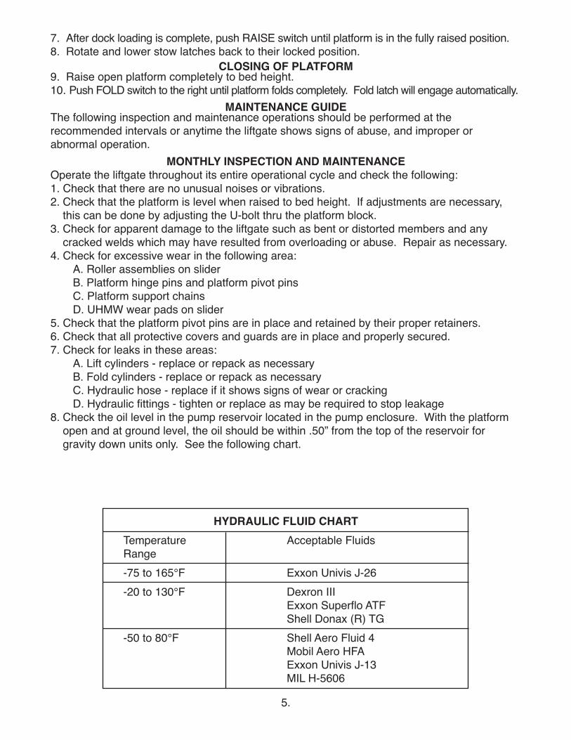
8. Check the oil level in the pump reservoir located in the pump enclosure. With the platformopen and at ground level, the oil should be within .50” from the top of the reservoir forgravity down units only. See the following chart.
HYDRAULIC FLUID CHARTTemperature Acceptable FluidsRange-75 to 165°F Exxon Univis J-26-20 to 130°F Dexron III
Exxon Superflo ATFShell Donax (R) TG
-50 to 80°F Shell Aero Fluid 4Mobil Aero HFAExxon Univis J-13MIL H-5606
6.
9. Check that all wiring and battery cable connections are tight and free of corrosion and all connections to be coated with dialectric grease.
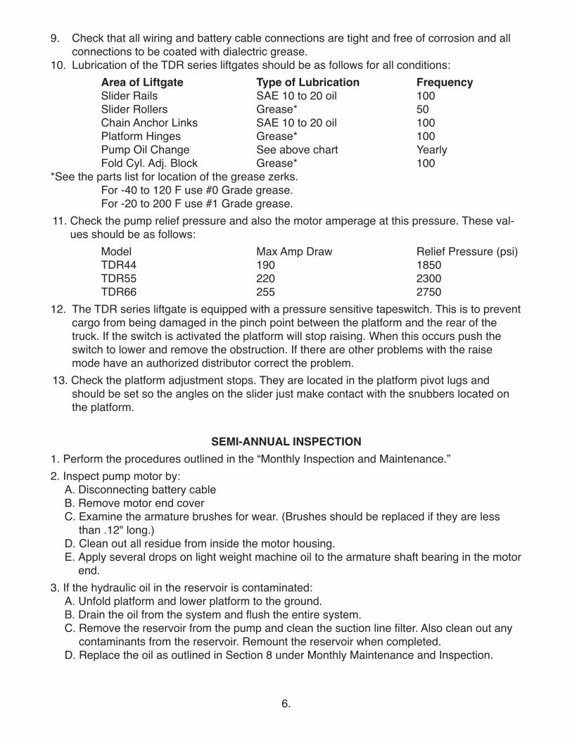
10. Lubrication of the TDR series liftgates should be as follows for all conditions:Area of Liftgate Type of Lubrication FrequencySlider Rails SAE 10 to 20 oil 100Slider Rollers Grease* 50Chain Anchor Links SAE 10 to 20 oil 100Platform Hinges Grease* 100Pump Oil Change See above chart YearlyFold Cyl. Adj. Block Grease* 100
*See the parts list for location of the grease zerks.For -40 to 120 F use #0 Grade grease.For -20 to 200 F use #1 Grade grease.
11. Check the pump relief pressure and also the motor amperage at this pressure. These val-ues should be as follows:
Model Max Amp Draw Relief Pressure (psi)TDR44 190 1850TDR55 220 2300TDR66 255 2750
12. The TDR series liftgate is equipped with a pressure sensitive tapeswitch. This is to preventcargo from being damaged in the pinch point between the platform and the rear of the truck. If the switch is activated the platform will stop raising. When this occurs push the switch to lower and remove the obstruction. If there are other problems with the raise mode have an authorized distributor correct the problem.
13. Check the platform adjustment stops. They are located in the platform pivot lugs and should be set so the angles on the slider just make contact with the snubbers located on the platform.
SEMI-ANNUAL INSPECTION1. Perform the procedures outlined in the “Monthly Inspection and Maintenance.”2. Inspect pump motor by:
A. Disconnecting battery cableB. Remove motor end coverC. Examine the armature brushes for wear. (Brushes should be replaced if they are less
than .12" long.)D. Clean out all residue from inside the motor housing.E. Apply several drops on light weight machine oil to the armature shaft bearing in the motor
end.3. If the hydraulic oil in the reservoir is contaminated:
A. Unfold platform and lower platform to the ground.B. Drain the oil from the system and flush the entire system.C. Remove the reservoir from the pump and clean the suction line filter. Also clean out any
contaminants from the reservoir. Remount the reservoir when completed.D. Replace the oil as outlined in Section 8 under Monthly Maintenance and Inspection.
7.
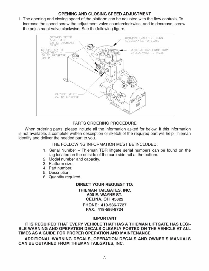
OPENING AND CLOSING SPEED ADJUSTMENT1. The opening and closing speed of the platform can be adjusted with the flow controls. To
increase the speed screw the adjustment valve counterclockwise, and to decrease, screwthe adjustment valve clockwise. See the following figure.
PARTS ORDERING PROCEDUREWhen ordering parts, please include all the information asked for below. If this information
is not available, a complete written description or sketch of the required part will help Thiemanidentify and deliver the needed part to you.
THE FOLLOWING INFORMATION MUST BE INCLUDED:1. Serial Number – Thieman TDR liftgate serial numbers can be found on the
tag located on the outside of the curb side rail at the bottom.2. Model number and capacity.3. Platform size.4. Part number.5. Description.6. Quantity required.
DIRECT YOUR REQUEST TO:THIEMAN TAILGATES, INC.
600 E. WAYNE ST.CELINA, OH 45822
PHONE: 419-586-7727FAX: 419-586-9724
IMPORTANTIT IS REQUIRED THAT EVERY VEHICLE THAT HAS A THIEMAN LIFTGATE HAS LEGI-
BLE WARNING AND OPERATION DECALS CLEARLY POSTED ON THE VEHICLE AT ALLTIMES AS A GUIDE FOR PROPER OPERATION AND MAINTENANCE.
ADDITIONAL WARNING DECALS, OPERATION DECALS AND OWNERʼS MANUALSCAN BE OBTAINED FROM THIEMAN TAILGATES, INC.
8.
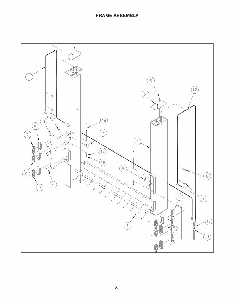
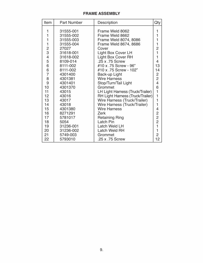
FRAME ASSEMBLY
Item Part Number Description Qty
1 31555-001 Frame Weld 8062 11 31555-002 Frame Weld 8662 11 31555-003 Frame Weld 8074, 8086 11 31555-004 Frame Weld 8674, 8686 12 27027 Cover 23 31618-001 Light Box Cover LH 14 31618-002 Light Box Cover RH 15 8109-014 .25 x .75 Screw 46 8111-002 #10 x .75 Screw - 96” 136 8111-002 #10 x .75 Screw - 102” 147 4301400 Back-up Light 28 4301381 Wire Harness 29 4301401 Stop/Turn/Tail Light 4
10 4301370 Grommet 611 43015 LH Light Harness (Truck/Trailer) 112 43016 RH Light Harness (Truck/Trailer) 113 43017 Wire Harness (Truck/Trailer) 114 43018 Wire Harness (Truck/Trailer) 115 4301380 Wire Harness 416 8271291 Zerk 217 5781017 Retaining Ring 218 5054 Latch Pin 219 31236-001 Latch Weld LH 120 31236-002 Latch Weld RH 121 5749-003 Grommet 222 5793010 .25 x .75 Screw 12
9.
FRAME ASSEMBLY
10.
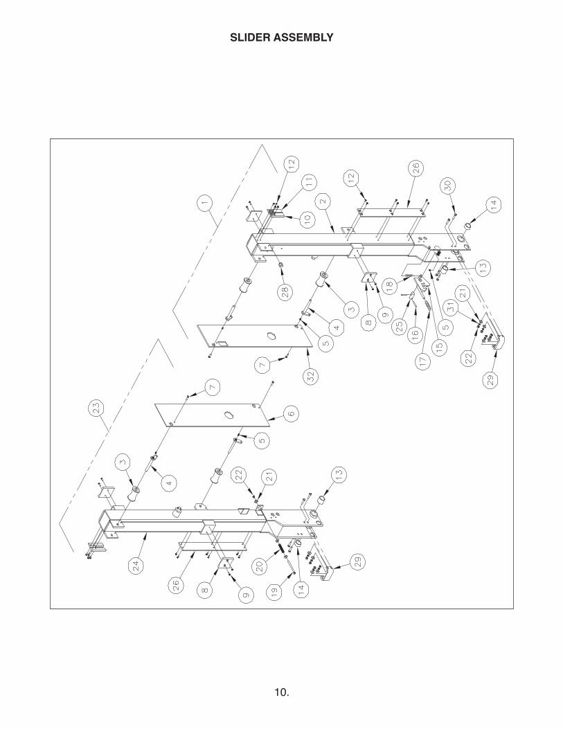
SLIDER ASSEMBLY
11.
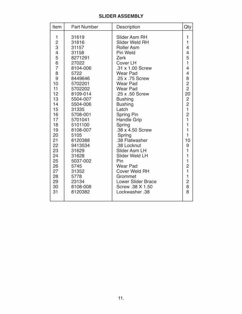
SLIDER ASSEMBLY
Item Part Number Description Qty
1 31619 Slider Asm RH 12 31616 Slider Weld RH 13 31157 Roller Asm 44 31158 Pin Weld 45 8271291 Zerk 56 27022 Cover LH 17 8104-006 .31 x 1.00 Screw 48 5722 Wear Pad 49 8449646 .25 x .75 Screw 8
10 5702201 Wear Pad 211 5702202 Wear Pad 212 8109-014 .25 x .50 Screw 2013 5504-007 Bushing 214 5504-006 Bushing 215 31335 Latch 116 5708-001 Spring Pin 217 5701041 Handle Grip 118 5101100 Spring 119 8108-007 .38 x 4.50 Screw 120 5105 Spring 121 8120388 .38 Flatwasher 1022 9413534 .38 Locknut 923 31629 Slider Asm LH 124 31628 Slider Weld LH 125 5037-002 Pin 126 5745 Wear Pad 227 31352 Cover Weld RH 128 5778 Grommet 129 23134 Lower Slider Brace 230 8108-008 Screw .38 X 1.50 831 8120382 Lockwasher .38 8
12.
PLATFORM ASSEMBLY - 62" & 74" DEEP
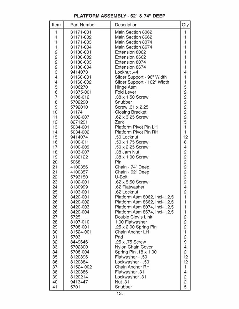
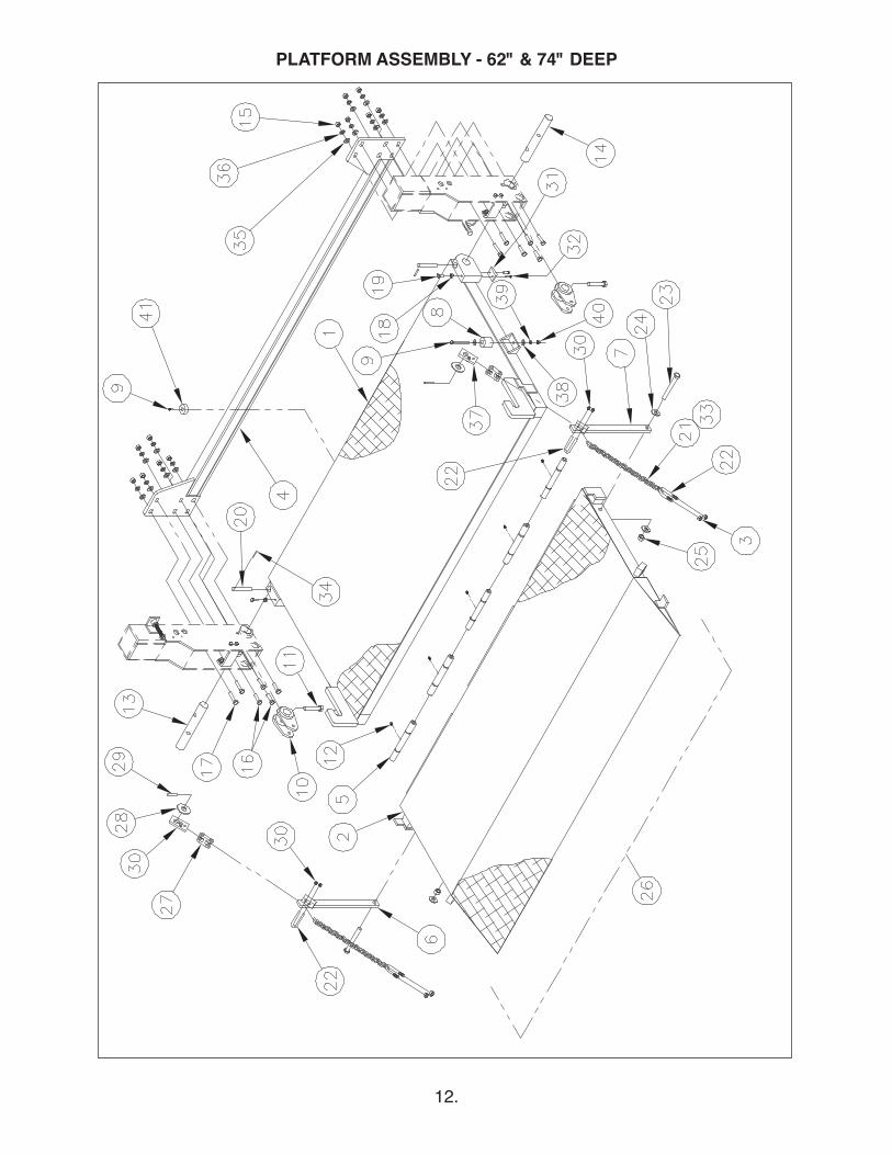
Item Part Number Description Qty1 31171-001 Main Section 8062 11 31171-002 Main Section 8662 11 31171-003 Main Section 8074 11 31171-004 Main Section 8674 12 31180-001 Extension 8062 12 31180-002 Extension 8662 12 31180-003 Extension 8074 12 31180-004 Extension 8674 13 9414073 Locknut .44 44 31160-001 Slider Support - 96" Width 14 31160-002 Slider Support - 102" Width 15 3106270 Hinge Asm 56 31375-001 Fold Lever 27 8108-012 .38 x 1.50 Screw 28 5702290 Snubber 29 5792010 Screw .31 x 2.25 2
10 31174 Closing Bracket 211 8102-007 .62 x 3.25 Screw 212 8271291 Zerk 513 5034-001 Platform Pivot Pin LH 114 5034-002 Platform Pivot Pin RH 115 9414074 .50 Locknut 1216 8100-011 .50 x 1.75 Screw 817 8100-009 .50 x 2.25 Screw 418 8103-007 .38 Jam Nut 219 8180122 .38 x 1.00 Screw 220 5068 Pin 221 4100356 Chain - 74" Deep 221 4100357 Chain - 62" Deep 222 5793150 U-Bolt 223 8102-001 .62 x 5.50 Screw 224 8130999 .62 Flatwasher 425 8103-001 .62 Locknut 226 3420-001 Platform Asm 8062, incl-1,2,5 126 3420-002 Platform Asm 8662, incl-1,2,5 126 3420-003 Platform Asm 8074, incl-1,2,5 126 3420-004 Platform Asm 8674, incl-1,2,5 127 5725 Double Clevis Link 228 8107-010 1.00 Flatwasher 229 5708-001 .25 x 2.00 Spring Pin 230 31524-001 Chain Anchor LH 131 5703 Pad 232 8449646 .25 x .75 Screw 933 5702300 Nylon Chain Cover 434 5708-004 Spring Pin .18 x 1.00 235 8120396 Flatwasher - .50 1236 8120384 Lockwasher - .50 1237 31524-002 Chain Anchor RH 138 8120386 Flatwasher .31 439 8120214 Lockwasher .31 240 9413447 Nut .31 241 5701 Snubber 5
13.
PLATFORM ASSEMBLY - 62" & 74" DEEP
14.
PLATFORM ASSEMBLY - 86" DEEP
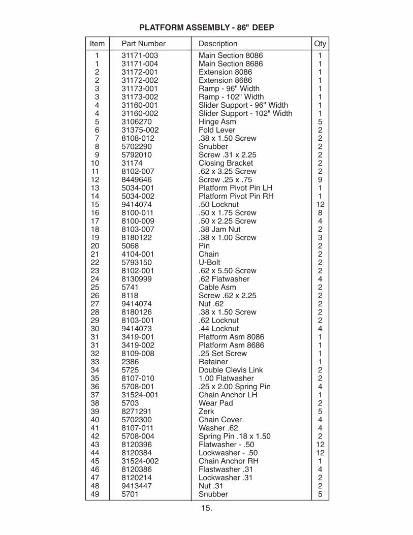
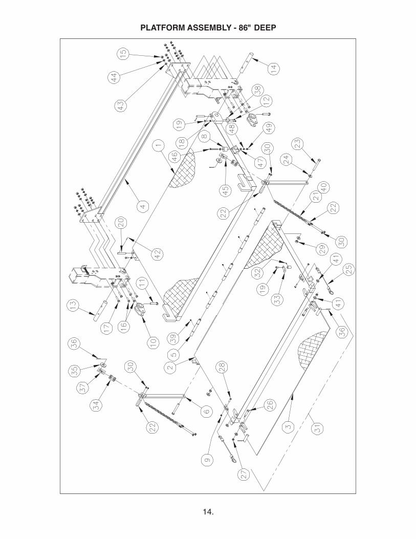
Item Part Number Description Qty1 31171-003 Main Section 8086 11 31171-004 Main Section 8686 12 31172-001 Extension 8086 12 31172-002 Extension 8686 13 31173-001 Ramp - 96" Width 13 31173-002 Ramp - 102" Width 14 31160-001 Slider Support - 96" Width 14 31160-002 Slider Support - 102" Width 15 3106270 Hinge Asm 56 31375-002 Fold Lever 27 8108-012 .38 x 1.50 Screw 28 5702290 Snubber 29 5792010 Screw .31 x 2.25 2
10 31174 Closing Bracket 211 8102-007 .62 x 3.25 Screw 212 8449646 Screw .25 x .75 913 5034-001 Platform Pivot Pin LH 114 5034-002 Platform Pivot Pin RH 115 9414074 .50 Locknut 1216 8100-011 .50 x 1.75 Screw 817 8100-009 .50 x 2.25 Screw 418 8103-007 .38 Jam Nut 219 8180122 .38 x 1.00 Screw 320 5068 Pin 221 4104-001 Chain 222 5793150 U-Bolt 223 8102-001 .62 x 5.50 Screw 224 8130999 .62 Flatwasher 425 5741 Cable Asm 226 8118 Screw .62 x 2.25 227 9414074 Nut .62 228 8180126 .38 x 1.50 Screw 229 8103-001 .62 Locknut 230 9414073 .44 Locknut 431 3419-001 Platform Asm 8086 131 3419-002 Platform Asm 8686 132 8109-008 .25 Set Screw 133 2386 Retainer 134 5725 Double Clevis Link 235 8107-010 1.00 Flatwasher 236 5708-001 .25 x 2.00 Spring Pin 437 31524-001 Chain Anchor LH 138 5703 Wear Pad 239 8271291 Zerk 540 5702300 Chain Cover 441 8107-011 Washer .62 442 5708-004 Spring Pin .18 x 1.50 243 8120396 Flatwasher - .50 1244 8120384 Lockwasher - .50 1245 31524-002 Chain Anchor RH 146 8120386 Flastwasher .31 447 8120214 Lockwasher .31 248 9413447 Nut .31 249 5701 Snubber 5
15.
PLATFORM ASSEMBLY - 86" DEEP
16.
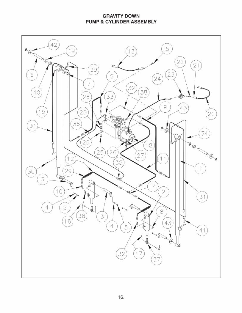
GRAVITY DOWNPUMP & CYLINDER ASSEMBLY
Item Part Number Description Qty
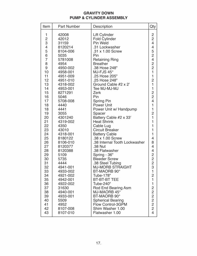
1 42008 Lift Cylinder 22 42012 Fold Cylinder 23 31159 Pin Weld 44 8120214 .31 Lockwasher 45 8104-006 .31 x 1.00 Screw 56 5035 Pin 27 5781008 Retaining Ring 48 4954 Breather 29 4950-002 .38 Hose 248" 210 4958-001 MJ-FJS 45° 111 4951-009 .25 Hose 205" 112 4951-010 .25 Hose 248" 213 4318-002 Ground Cable #2 x 2' 114 4953-001 Tee MJ-MJ-MJ 115 8271291 Zerk 216 5046 Pin 217 5708-008 Spring Pin 418 4440 Power Unit 118 4441 Power Unit w/ Handpump 119 3055 Spacer 220 4301240 Battery Cable #2 x 33' 121 4319-002 Heat Shrink 122 4350 Cable Lug 123 43010 Circuit Breaker 124 4318-001 Battery Cable 125 8180122 .38 x 1.00 Screw 426 8106-010 .38 Internal Tooth Lockwasher 827 8120377 .38 Nut 428 8120388 .38 Flatwasher 429 5109 Spring - 36" 230 5735 Bleeder Screw 231 4444 .38 Steel Tubing 232 4941-001 MJ-MORB STRAIGHT 333 4933-002 BT-MAORB 90° 134 4921-002 Tube-178" 235 4942-001 BT-BT-BT TEE 136 4922-002 Tube-240" 137 31630 Rod End Bearing Asm 238 4940-001 MJ-MAORB 45° 239 4933-001 BT-MAORB 90° 240 5509 Spherical Bearing 241 4952 Flow Control-3GPM 242 8107-008 Shim Washer 1.00 243 8107-010 Flatwasher 1.00 4
17.
GRAVITY DOWNPUMP & CYLINDER ASSEMBLY

18.
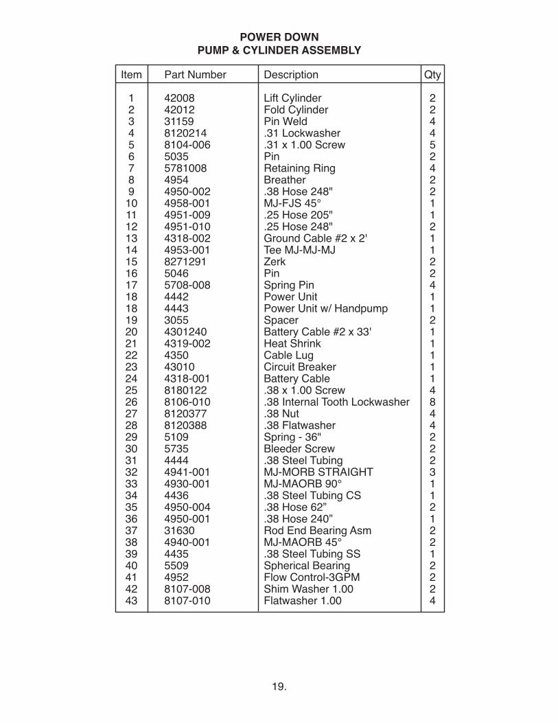
POWER DOWNPUMP & CYLINDER ASSEMBLY
19.
Item Part Number Description Qty
1 42008 Lift Cylinder 22 42012 Fold Cylinder 23 31159 Pin Weld 44 8120214 .31 Lockwasher 45 8104-006 .31 x 1.00 Screw 56 5035 Pin 27 5781008 Retaining Ring 48 4954 Breather 29 4950-002 .38 Hose 248" 210 4958-001 MJ-FJS 45° 111 4951-009 .25 Hose 205" 112 4951-010 .25 Hose 248" 213 4318-002 Ground Cable #2 x 2' 114 4953-001 Tee MJ-MJ-MJ 115 8271291 Zerk 216 5046 Pin 217 5708-008 Spring Pin 418 4442 Power Unit 118 4443 Power Unit w/ Handpump 119 3055 Spacer 220 4301240 Battery Cable #2 x 33' 121 4319-002 Heat Shrink 122 4350 Cable Lug 123 43010 Circuit Breaker 124 4318-001 Battery Cable 125 8180122 .38 x 1.00 Screw 426 8106-010 .38 Internal Tooth Lockwasher 827 8120377 .38 Nut 428 8120388 .38 Flatwasher 429 5109 Spring - 36" 230 5735 Bleeder Screw 231 4444 .38 Steel Tubing 232 4941-001 MJ-MORB STRAIGHT 333 4930-001 MJ-MAORB 90° 134 4436 .38 Steel Tubing CS 135 4950-004 .38 Hose 62” 236 4950-001 .38 Hose 240” 137 31630 Rod End Bearing Asm 238 4940-001 MJ-MAORB 45° 239 4435 .38 Steel Tubing SS 140 5509 Spherical Bearing 241 4952 Flow Control-3GPM 242 8107-008 Shim Washer 1.00 243 8107-010 Flatwasher 1.00 4
POWER DOWNPUMP & CYLINDER ASSEMBLY
Item Part Number Description Qty
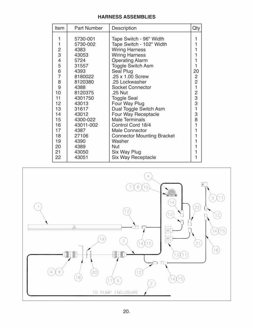
1 5730-001 Tape Switch - 96" Width 11 5730-002 Tape Switch - 102" Width 12 4383 Wiring Harness 13 43053 Wiring Harness 14 5724 Operating Alarm 15 31557 Toggle Switch Asm 16 4393 Seal Plug 207 8180022 .25 x 1.00 Screw 28 8120380 .25 Lockwasher 29 4388 Socket Connector 1
10 8120375 .25 Nut 211 4301750 Toggle Seal 312 43013 Four Way Plug 313 31617 Dual Toggle Switch Asm 114 43012 Four Way Receptacle 315 4300-022 Male Terminals 816 43011-002 Control Cord 18/4 117 4387 Male Connector 118 27106 Connector Mounting Bracket 119 4390 Washer 120 4389 Nut 121 43050 Six Way Plug 122 43051 Six Way Receptacle 1
20.
HARNESS ASSEMBLIES
21.
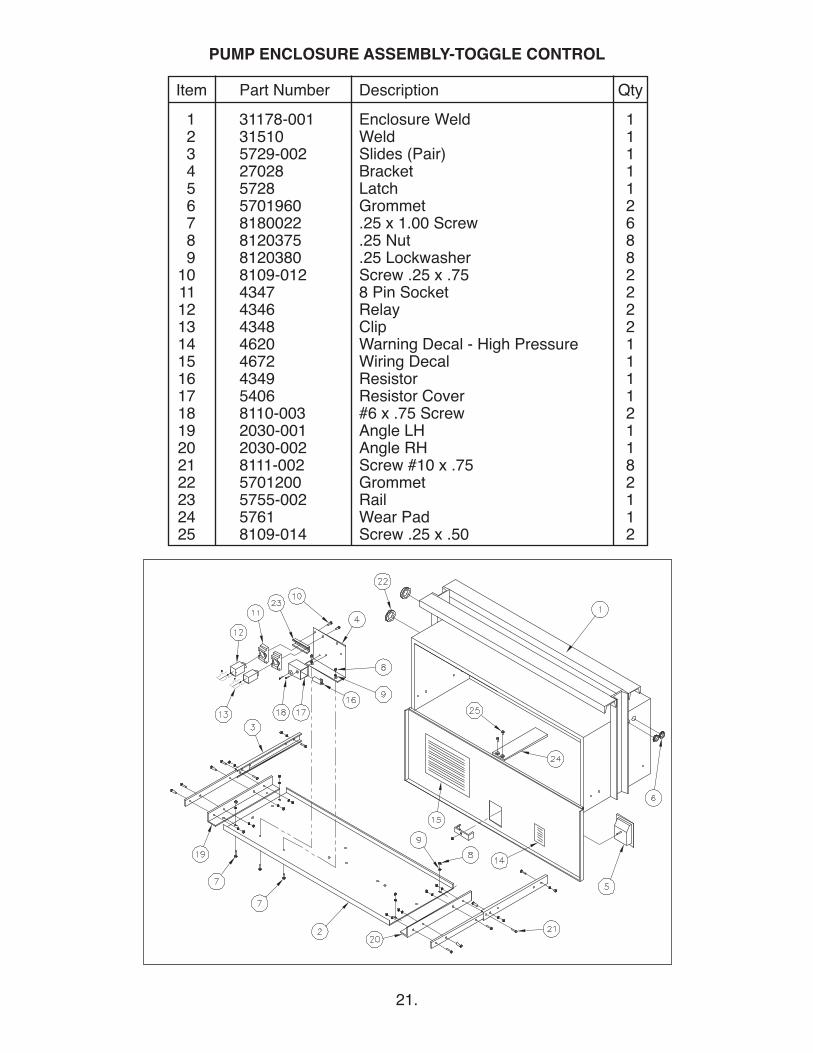
Item Part Number Description Qty1 31178-001 Enclosure Weld 12 31510 Weld 13 5729-002 Slides (Pair) 14 27028 Bracket 15 5728 Latch 16 5701960 Grommet 27 8180022 .25 x 1.00 Screw 68 8120375 .25 Nut 89 8120380 .25 Lockwasher 8
10 8109-012 Screw .25 x .75 211 4347 8 Pin Socket 212 4346 Relay 213 4348 Clip 214 4620 Warning Decal - High Pressure 115 4672 Wiring Decal 116 4349 Resistor 117 5406 Resistor Cover 118 8110-003 #6 x .75 Screw 219 2030-001 Angle LH 120 2030-002 Angle RH 121 8111-002 Screw #10 x .75 822 5701200 Grommet 223 5755-002 Rail 124 5761 Wear Pad 125 8109-014 Screw .25 x .50 2
PUMP ENCLOSURE ASSEMBLY-TOGGLE CONTROL
22.
Item Part Name Part Number
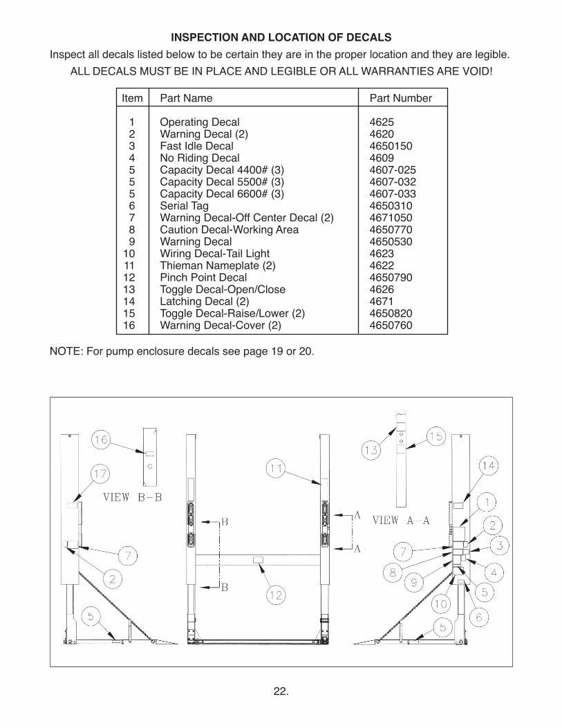
1 Operating Decal 46252 Warning Decal (2) 46203 Fast Idle Decal 46501504 No Riding Decal 46095 Capacity Decal 4400# (3) 4607-0255 Capacity Decal 5500# (3) 4607-0325 Capacity Decal 6600# (3) 4607-0336 Serial Tag 46503107 Warning Decal-Off Center Decal (2) 46710508 Caution Decal-Working Area 46507709 Warning Decal 4650530
10 Wiring Decal-Tail Light 462311 Thieman Nameplate (2) 462212 Pinch Point Decal 465079013 Toggle Decal-Open/Close 462614 Latching Decal (2) 467115 Toggle Decal-Raise/Lower (2) 465082016 Warning Decal-Cover (2) 4650760
INSPECTION AND LOCATION OF DECALSInspect all decals listed below to be certain they are in the proper location and they are legible.
ALL DECALS MUST BE IN PLACE AND LEGIBLE OR ALL WARRANTIES ARE VOID!
NOTE: For pump enclosure decals see page 19 or 20.
23.
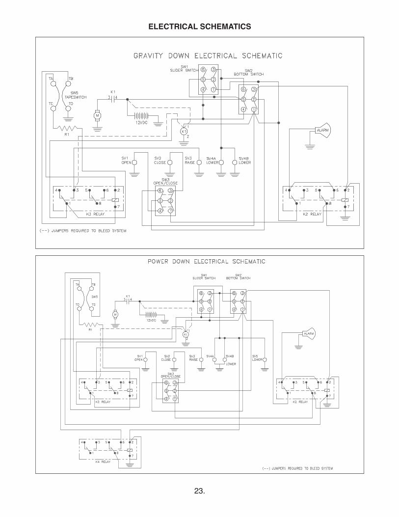
ELECTRICAL SCHEMATICS
24.
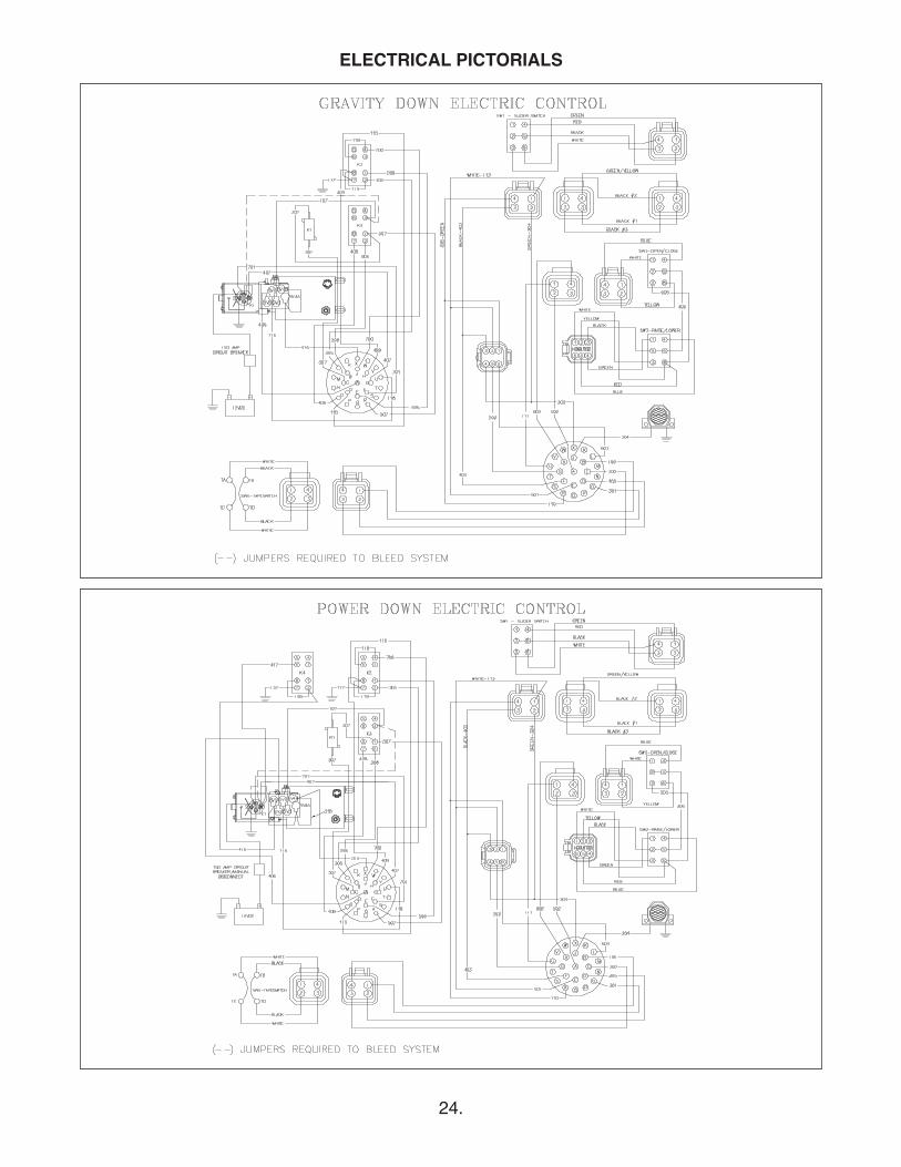
ELECTRICAL PICTORIALS
25.
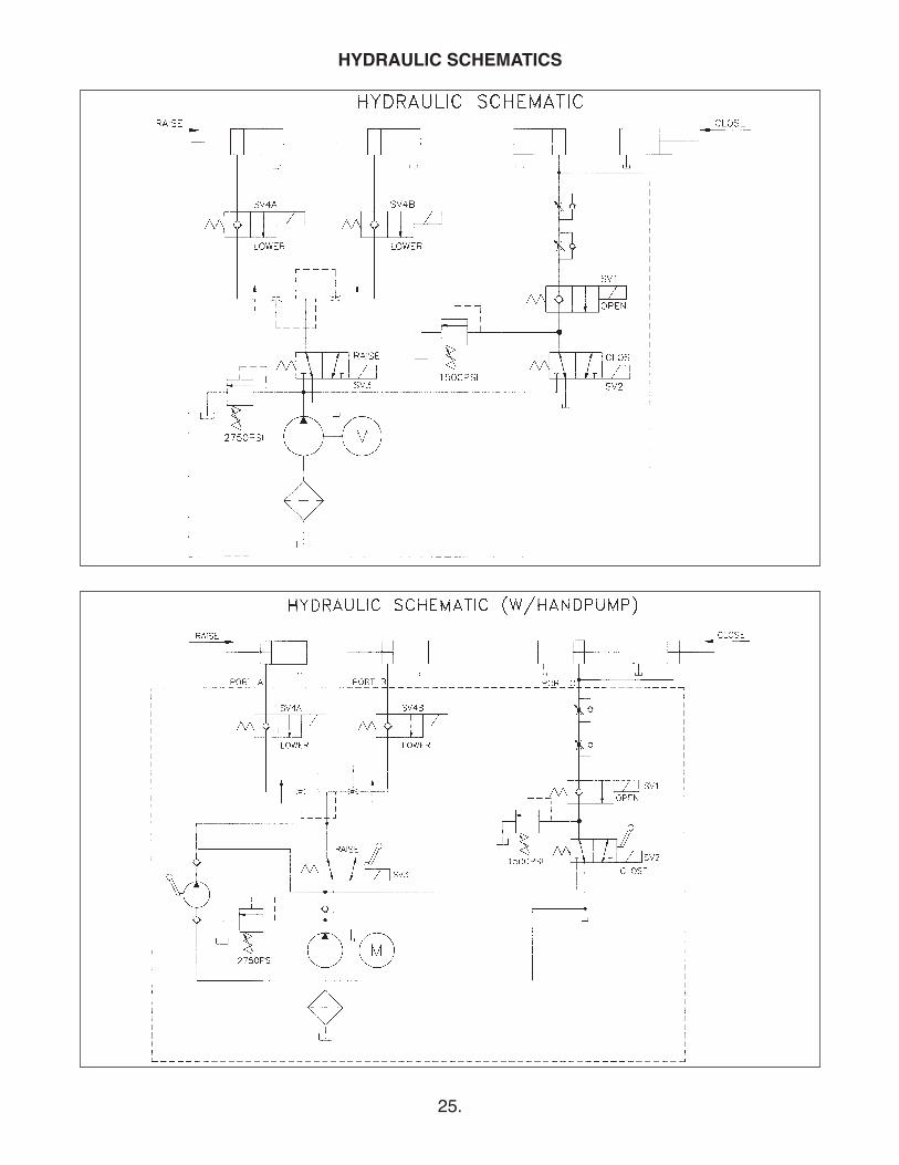
HYDRAULIC SCHEMATICS

26.
27.
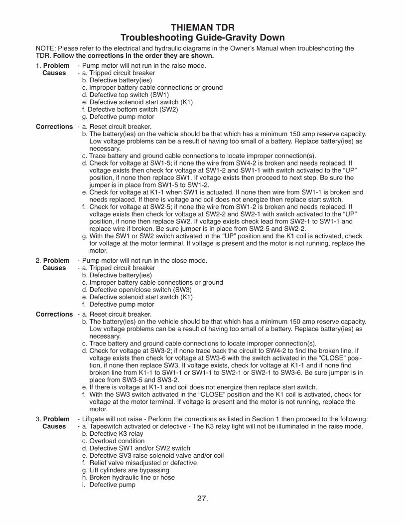
THIEMAN TDRTroubleshooting Guide-Gravity Down
NOTE: Please refer to the electrical and hydraulic diagrams in the Ownerʼs Manual when troubleshooting theTDR. Follow the corrections in the order they are shown.1. Problem - Pump motor will not run in the raise mode.
Causes - a. Tripped circuit breakerb. Defective battery(ies)c. Improper battery cable connections or groundd. Defective top switch (SW1)e. Defective solenoid start switch (K1)f. Defective bottom switch (SW2)g. Defective pump motor
Corrections - a. Reset circuit breaker.b. The battery(ies) on the vehicle should be that which has a minimum 150 amp reserve capacity.
Low voltage problems can be a result of having too small of a battery. Replace battery(ies) asnecessary.
c. Trace battery and ground cable connections to locate improper connection(s).d. Check for voltage at SW1-5; if none the wire from SW4-2 is broken and needs replaced. If
voltage exists then check for voltage at SW1-2 and SW1-1 with switch activated to the “UP”position, if none then replace SW1. If voltage exists then proceed to next step. Be sure thejumper is in place from SW1-5 to SW1-2.
e. Check for voltage at K1-1 when SW1 is actuated. If none then wire from SW1-1 is broken andneeds replaced. If there is voltage and coil does not energize then replace start switch.
f. Check for voltage at SW2-5; if none the wire from SW1-2 is broken and needs replaced. Ifvoltage exists then check for voltage at SW2-2 and SW2-1 with switch activated to the “UP”position, if none then replace SW2. If voltage exists check lead from SW2-1 to SW1-1 andreplace wire if broken. Be sure jumper is in place from SW2-5 and SW2-2.
g. With the SW1 or SW2 switch activated in the “UP” position and the K1 coil is activated, checkfor voltage at the motor terminal. If voltage is present and the motor is not running, replace themotor.
2. Problem - Pump motor will not run in the close mode.Causes - a. Tripped circuit breaker
b. Defective battery(ies)c. Improper battery cable connections or groundd. Defective open/close switch (SW3)e. Defective solenoid start switch (K1)f. Defective pump motor
Corrections - a. Reset circuit breaker.b. The battery(ies) on the vehicle should be that which has a minimum 150 amp reserve capacity.
Low voltage problems can be a result of having too small of a battery. Replace battery(ies) asnecessary.
c. Trace battery and ground cable connections to locate improper connection(s).d. Check for voltage at SW3-2; if none trace back the circuit to SW4-2 to find the broken line. If
voltage exists then check for voltage at SW3-6 with the switch activated in the “CLOSE” posi-tion, if none then replace SW3. If voltage exists, check for voltage at K1-1 and if none findbroken line from K1-1 to SW1-1 or SW1-1 to SW2-1 or SW2-1 to SW3-6. Be sure jumper is inplace from SW3-5 and SW3-2.
e. If there is voltage at K1-1 and coil does not energize then replace start switch.f. With the SW3 switch activated in the “CLOSE” position and the K1 coil is activated, check for
voltage at the motor terminal. If voltage is present and the motor is not running, replace themotor.
3. Problem - Liftgate will not raise - Perform the corrections as listed in Section 1 then proceed to the following:Causes - a. Tapeswitch activated or defective - The K3 relay light will not be illuminated in the raise mode.
b. Defective K3 relayc. Overload conditiond. Defective SW1 and/or SW2 switche. Defective SV3 raise solenoid valve and/or coilf. Relief valve misadjusted or defectiveg. Lift cylinders are bypassingh. Broken hydraulic line or hosei. Defective pump
28.
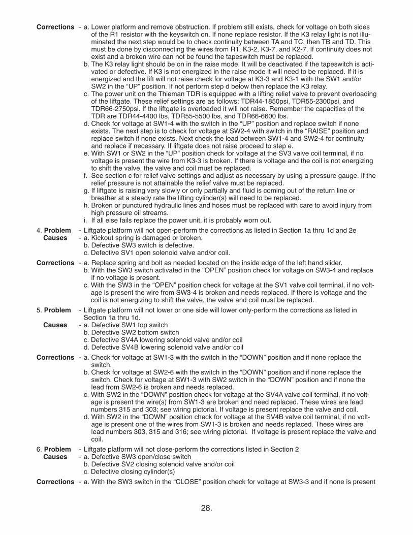
Corrections - a. Lower platform and remove obstruction. If problem still exists, check for voltage on both sidesof the R1 resistor with the keyswitch on. If none replace resistor. If the K3 relay light is not illu-minated the next step would be to check continuity between TA and TC, then TB and TD. Thismust be done by disconnecting the wires from R1, K3-2, K3-7, and K2-7. If continuity does notexist and a broken wire can not be found the tapeswitch must be replaced.
b. The K3 relay light should be on in the raise mode. It will be deactivated if the tapeswitch is acti-vated or defective. If K3 is not energized in the raise mode it will need to be replaced. If it isenergized and the lift will not raise check for voltage at K3-3 and K3-1 with the SW1 and/orSW2 in the “UP” position. If not perform step d below then replace the K3 relay.
c. The power unit on the Thieman TDR is equipped with a lifting relief valve to prevent overloadingof the liftgate. These relief settings are as follows: TDR44-1850psi, TDR55-2300psi, andTDR66-2750psi. If the liftgate is overloaded it will not raise. Remember the capacities of theTDR are TDR44-4400 lbs, TDR55-5500 lbs, and TDR66-6600 lbs.
d. Check for voltage at SW1-4 with the switch in the “UP” position and replace switch if noneexists. The next step is to check for voltage at SW2-4 with switch in the “RAISE” position andreplace switch if none exists. Next check the lead between SW1-4 and SW2-4 for continuityand replace if necessary. If liftgate does not raise proceed to step e.
e. With SW1 or SW2 in the “UP” position check for voltage at the SV3 valve coil terminal, if novoltage is present the wire from K3-3 is broken. If there is voltage and the coil is not energizingto shift the valve, the valve and coil must be replaced.
f. See section c for relief valve settings and adjust as necessary by using a pressure gauge. If therelief pressure is not attainable the relief valve must be replaced.
g. If liftgate is raising very slowly or only partially and fluid is coming out of the return line orbreather at a steady rate the lifting cylinder(s) will need to be replaced.
h. Broken or punctured hydraulic lines and hoses must be replaced with care to avoid injury fromhigh pressure oil streams.
i. If all else fails replace the power unit, it is probably worn out.4. Problem - Liftgate platform will not open-perform the corrections as listed in Section 1a thru 1d and 2e
Causes - a. Kickout spring is damaged or broken.b. Defective SW3 switch is defective.c. Defective SV1 open solenoid valve and/or coil.
Corrections - a. Replace spring and bolt as needed located on the inside edge of the left hand slider.b. With the SW3 switch activated in the “OPEN” position check for voltage on SW3-4 and replace
if no voltage is present.c. With the SW3 in the “OPEN” position check for voltage at the SV1 valve coil terminal, if no volt-
age is present the wire from SW3-4 is broken and needs replaced. If there is voltage and thecoil is not energizing to shift the valve, the valve and coil must be replaced.
5. Problem - Liftgate platform will not lower or one side will lower only-perform the corrections as listed inSection 1a thru 1d.
Causes - a. Defective SW1 top switchb. Defective SW2 bottom switchc. Defective SV4A lowering solenoid valve and/or coild. Defective SV4B lowering solenoid valve and/or coil
Corrections - a. Check for voltage at SW1-3 with the switch in the “DOWN” position and if none replace theswitch.
b. Check for voltage at SW2-6 with the switch in the “DOWN” position and if none replace theswitch. Check for voltage at SW1-3 with SW2 switch in the “DOWN” position and if none thelead from SW2-6 is broken and needs replaced.
c. With SW2 in the “DOWN” position check for voltage at the SV4A valve coil terminal, if no volt-age is present the wire(s) from SW1-3 are broken and need replaced. These wires are leadnumbers 315 and 303; see wiring pictorial. If voltage is present replace the valve and coil.
d. With SW2 in the “DOWN” position check for voltage at the SV4B valve coil terminal, if no volt-age is present one of the wires from SW1-3 is broken and needs replaced. These wires arelead numbers 303, 315 and 316; see wiring pictorial. If voltage is present replace the valve andcoil.
6. Problem - Liftgate platform will not close-perform the corrections listed in Section 2Causes - a. Defective SW3 open/close switch
b. Defective SV2 closing solenoid valve and/or coilc. Defective closing cylinder(s)
Corrections - a. With the SW3 switch in the “CLOSE” position check for voltage at SW3-3 and if none is present

this switch needs to be replaced.b. Check for voltage at the coil terminal of the SV2 valve and if none exists the wire from SW3-3
will need replaced. Otherwise the SV2 valve needs replaced if voltage is present and the plat-form is not closing.
c. If fluid is leaking from the closing cylinder(s) breather port or the rod seal at a steady stream thecylinder will need to be replaced or repaired.
7. Problem - One side or the other, or both sides of the platform are drifting at a rapid rate-more than 1" per dayCauses - a. Air in lifting hydraulic circuit
b. Defective SV4A and/or SV4B solenoid valvec. Defective cylinder piston seals
Corrections - a. Raise the liftgate completely then raise the latch on the curb side then open the platform withthe toggle switch. Once the platform is completely open, lower the platform to the ground andthen raise the platform completely to bed height and run the pump for five seconds to force anyair out of the system.Additional bleeding of the system can be done by fully extending the lift cylinders. It may benecessary to raise the truck or trailer to obtain a bed of 60 inches. Open one bleeder screw, seeparts list for location of this screw on the cylinder valve block. Connect a jumper wire from K1-1to K3-3 and a loose wire connected to K1-1. Touch the loose lead from K1-1 to K1-4 and holdthe toggle switch in the “Down” position. This will force out any air in the cylinder. Then closethe bleeder valve when a red stream of fluid is present. Repeat this procedure for the otherside.
b. Replace the solenoid valve for whichever side is drifting.c. Check the return lines for an excessive amount of fluid bypassing the piston seals and repair or
replace the cylinder as necessary.8. Problem - Alarm does not operate in the “UP”, “DOWN”, “OPEN”, and “CLOSE” only operations - perform
the corrections as listed in Section 1a thru 1g then proceed below. The alarm does not soundwhen the SW1 switch is activated in the “DOWN” position.
Causes - a. Defective alarm- b. Defective bottom switch SW2- c. Defective open/close switch SW3- d. Defective K2 relay
Corrections - a. Activate the SW2 switch in the “UP” position and check for voltage at K2-2. If voltage is presentand alarm does not sound, check the ground lead on the alarm for a proper ground and replacealarm if ground is good. If no voltage is present proceed to step b.
b. With the SW2 switch in the “DOWN” position check for voltage at SW2-3 and if none existsreplace SW2. If voltage is present check for voltage at K2-2 and if none exists the wire fromSW2-3 is broken and needs replaced. Check for voltage at K2-1 with the SW2 switch in the“UP” position and if none is present the wire from SW2-1 is broken and needs replaced.
c. Activate the SW3 switch to the “OPEN” position and check for voltage at SW3-1 and if noneexist replace the SW3 switch. If there is voltage present check for voltage at K2-8 and if none ispresent the wire from SW3-1 is broken and needs replaced.
d. Anytime SW2 is activated in the “DOWN” position or the SW3 is activated in the “OPEN” posi-tion the K2 relay should be energized. If the relay is not energizing it will need to be replaced. Ifthe relay is energized and the alarm is not sounding check for voltage at K2-8 with SW2 in the“DOWN” position and if none is present the wire from K2-2 is broken and needs replaced. Ifthere is voltage at K2-8 and the relay is energized check for voltage at K2-6 and if there is nonethe relay must be replaced. If voltage does exist here then check voltage at K2-4 and if nonethe wire from K2-6 is broken and needs replaced.
If you have any questions or problems that are not covered in this guide please call Thiemanʼs EngineeringDepartment at 1-800-524-5210.
29.

TAILLIGHT PICTORIAL
30.


Rev. 9/08 • 2.5C • MP65845