system (wms) watershed modeling drainage areas with ... - delineating drainage areas.pdffor a more...
TRANSCRIPT

[Type text] [Type text] [Type text]
1
Office of Design Policy & Support
Delineating Offsite Drainage Areas with Watershed Modeling
System (WMS)
Developed By Office of Design Policy & SupportProduct Version WMS – 10.0.13
Microstation v8i SS2
Document Revision Version _1.30
Release Date 4-29-16

[Type text] [Type text] [Type text]
2
Objective
To delineate offsite Drainage Areas using WMS (Watershed Modeling System), in conjunction with InRoads and Microstation.
[Type text] [Type text] [Type text]
3
Table of Contents
Creating Drainage DXF Reference File for WMS ...........................................................................4
Delineating Drainage Areas .........................................................................................................6
Set Projection.......................................................................................................................6
Open DXF File.......................................................................................................................7
Download and Convert Elevation Data to DEM....................................................................8
Compute Flow Direction/Accumulation ...............................................................................9
Place Outlet Points.............................................................................................................11
Delineate Initial Watershed ...............................................................................................12
Creating and Editing Stream/Feature Arcs .........................................................................14
Stream Arcs ................................................................................................................14
Feature Arcs ...............................................................................................................18
Smoothing Boundaries.......................................................................................................22
Exporting Drainage Area Boundaries .........................................................................................23

[Type text] [Type text] [Type text]
4
Creating Drainage DXF Reference File for WMS
In Microstation, create a (or use an existing) DGN file that includes the following:1. All drainage structures (proposed and existing), including flow arrows2. All ditches, including flow arrows3. Cut and Fill limits4. Centerline and stationing
Before continuing, you must define the coordinate system of your file. Enter the appropriate command in the Microstation Command window (and press enter):
For Georgia West Zone: geocoordinate assign GA83-WF
For Georgia East Zone: geocoordinate assign GA83-EF
It is best to not have any Reference Files in this DGN file, so if you need to use a Reference File, then Merge Into Master and then drop the Reference File.
For a more accurate drainage area, you should determine the flow directions along the Cut and Fill Limits. The reason you need to do this is that in WMS you will be creating Stream Arcs to keep the runoff from crossing over the roadway.
Once you have a complete Drainage DGN file to use as a Reference in WMS, you will need to export it as a DXF File. File>Export>DGN,DWG,DXF…
Click on the Save as type: pull-down and choose Autodesk® DXF Files (*.dxf). Next, click on Options. Click on Line Weights, under the General tab. Change the DWG Weight values for Line Weights 2-4 to match the values in the screen shot below. Otherwise, the lines will be too thick in WMS.

[Type text] [Type text] [Type text]
5
Microstation will remember (and keep) these values, even when you open a new file. If you ever want to change back to the default values, here they are:
Click Ok, and then Save. You now have a DXF Reference File to open in WMS with all of your drainage structures and ditches.

[Type text] [Type text] [Type text]
6
Delineating Drainage Areas
Set Projection
Open WMS. Before opening the DXF that you just created, you should first set the Projection.
Click on Edit > Current Projection…
Click on the Set Projection button.
In most cases, you will match the settings shown in the screen capture on the right, with the exception of the Zone. The Zone will either be Georgia West (FIPS 1002) or Georgia East (FIPS 1001), depending on where your project is located. Click OK when you are done, and OK again to get back to the main WMS screen.
[Type text] [Type text] [Type text]
7
Open DXF File
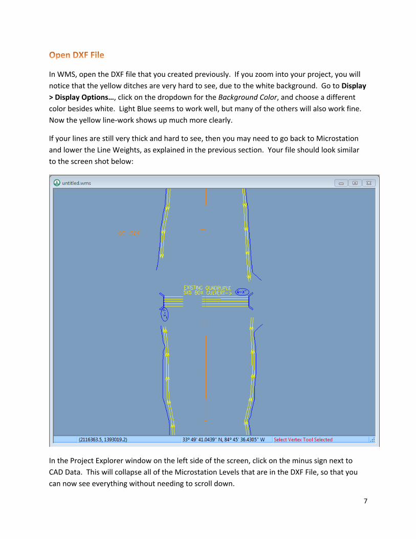
In WMS, open the DXF file that you created previously. If you zoom into your project, you will notice that the yellow ditches are very hard to see, due to the white background. Go to Display > Display Options…, click on the dropdown for the Background Color, and choose a different color besides white. Light Blue seems to work well, but many of the others will also work fine. Now the yellow line-work shows up much more clearly.
If your lines are still very thick and hard to see, then you may need to go back to Microstation and lower the Line Weights, as explained in the previous section. Your file should look similar to the screen shot below:
In the Project Explorer window on the left side of the screen, click on the minus sign next to CAD Data. This will collapse all of the Microstation Levels that are in the DXF File, so that you can now see everything without needing to scroll down.
[Type text] [Type text] [Type text]
8
Download and Convert Elevation Data to DEM
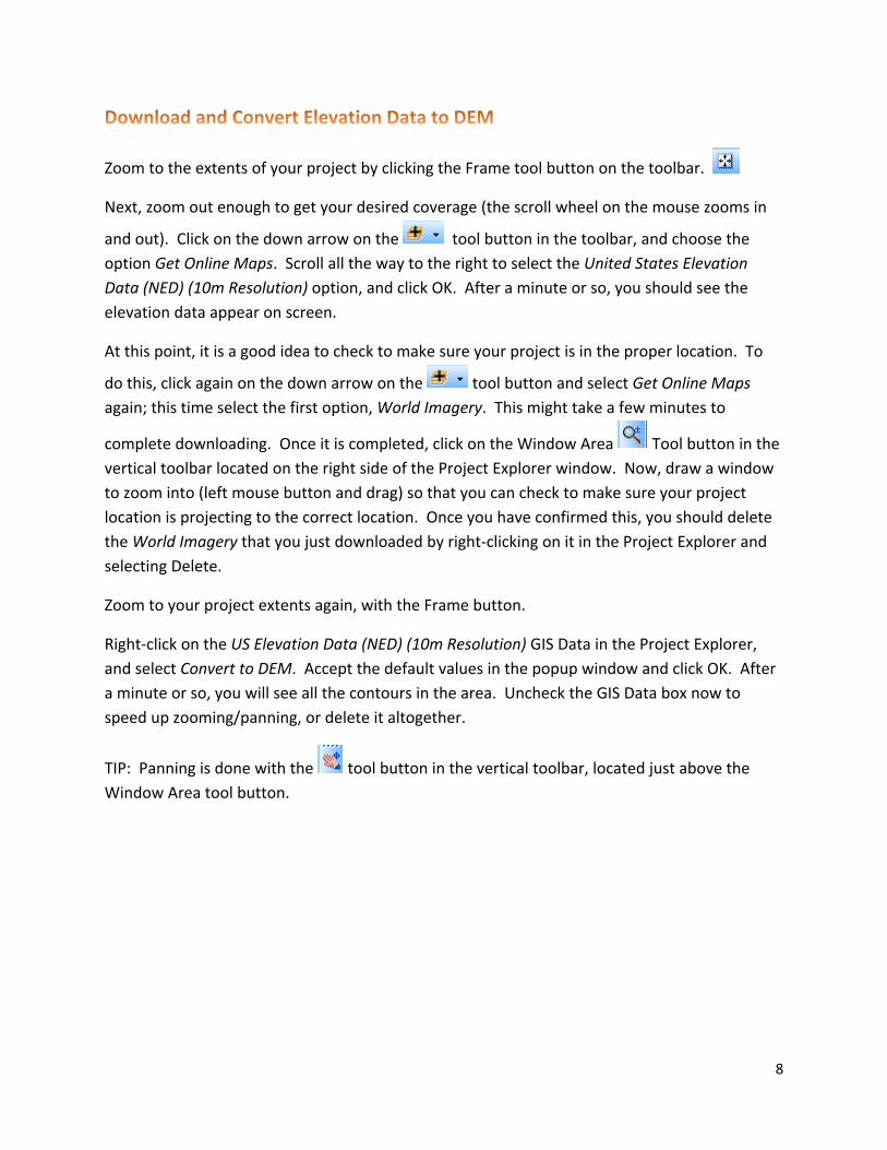
Zoom to the extents of your project by clicking the Frame tool button on the toolbar.
Next, zoom out enough to get your desired coverage (the scroll wheel on the mouse zooms in
and out). Click on the down arrow on the tool button in the toolbar, and choose the option Get Online Maps. Scroll all the way to the right to select the United States Elevation Data (NED) (10m Resolution) option, and click OK. After a minute or so, you should see the elevation data appear on screen.
At this point, it is a good idea to check to make sure your project is in the proper location. To
do this, click again on the down arrow on the tool button and select Get Online Maps again; this time select the first option, World Imagery. This might take a few minutes to
complete downloading. Once it is completed, click on the Window Area Tool button in the vertical toolbar located on the right side of the Project Explorer window. Now, draw a window to zoom into (left mouse button and drag) so that you can check to make sure your project location is projecting to the correct location. Once you have confirmed this, you should delete the World Imagery that you just downloaded by right-clicking on it in the Project Explorer and selecting Delete.
Zoom to your project extents again, with the Frame button.
Right-click on the US Elevation Data (NED) (10m Resolution) GIS Data in the Project Explorer, and select Convert to DEM. Accept the default values in the popup window and click OK. After a minute or so, you will see all the contours in the area. Uncheck the GIS Data box now to speed up zooming/panning, or delete it altogether.
TIP: Panning is done with the tool button in the vertical toolbar, located just above the Window Area tool button.

[Type text] [Type text] [Type text]
9
Compute Flow Direction/Accumulation
There is a Hydrologic Modeling Wizard that steps you through the entire process of delineating a watershed; however, once you manually draw or edit Stream Arcs (or Feature Arcs), they will be deleted if you use the Wizard. It is good to use the Wizard to delineate your initial Drainage Basins, but once you make any edits to existing Stream/Feature Arcs (or draw any new ones), you should not use the Wizard again (or else, you will lose all of the work you did manually). This section will use the Wizard; manual steps will be shown later in the guide.
Select the Hydrologic Modeling Wizard and then select the Compute Flow Directions and Accumulations (TOPAZ) tab on the left side of the dialog box. Change the units of area or distance, if needed. The Min flow accumulation threshold: value controls how many “streams” will show up. These “streams” are not necessarily existing rivers or creeks, but rather general flows based upon the DEM Data. You will very likely need to try different values to get your desired results. The lower the value used, the more “streams” that will appear. Try a value of 1 square mile, and then change it to a value of 0.5 square miles. If you need more flows, simply continue reducing this value until you reach the desired amount of visible flows. You will need these “streams” in order to place your Outlet points and to create Stream Arcs later. You can easily and quickly change these values on-the-fly by clicking the “Apply to Display” button after changing the value.
Once you have entered a value, click “Compute TOPAZ”. It may take approximately 1-2 minutes for the process to complete. Once you see the Abort button change to a Close button in the popup window, click on Close. You should now see these “streams” on your screen. See screen shots below for 2 examples:

[Type text] [Type text] [Type text]
10
Min Flow Accumulation Threshold value of 0.1 SQM:
Min Flow Accumulation Threshold value of 0.01 SQM:

[Type text] [Type text] [Type text]
11
Place Outlet Points
Now it is time to place Outlet Points on your major drainage structures. These WMS Outlet Points are actually the Inlets of your drainage structures. Outlet Points must be placed on an actual “stream”, or Flow Accumulation. Existing culverts and cross drains should already have streams relatively close to where these existing structures are, although you may want to edit/move them later if they are not close enough to the actual drainage structure. If there is no stream near, then you will need to draw a Stream Arc (see next section) instead of placing an Outlet Point. Decreasing the Min Flow Accumulation Threshold value may help as well. See screen shot below as an example:
To place an Outlet Point using the Wizard, click on the Choose Outlet Locations option on the left side of the Wizard dialog box (or click the Next> button if you are currently in the Compute Flow Directions and Accumulations section). Here you can choose to either create or delete an outlet point (to delete an outlet point, you must select it first).
Place Outlet Points at all culverts and cross drains. Also, when a stream crosses under a bridge, you should place an Outlet Point on the exit side.

[Type text] [Type text] [Type text]
12
Delineate Initial Watershed
After you have placed all desired Outlet Points at major drainage inlets (and stream crossings at bridge overpasses), and while still in the Hydrologic Modeling Wizard, click on the Next> button.
Here, you can change the Stream Threshold value if you like. You can also set a maximum area for your Basins, if desired, in which case it will sub-divide your Basins. Once you are ready, click the Delineate Watershed button. It might take several minutes to complete (possibly more than 10), depending on the size of your project and the stream system. Below is a screen shot of an example project’s initial watershed delineation:

[Type text] [Type text] [Type text]
13
As you can see on the western and southern borders, there was not quite enough coverage, as evidenced by the long straight Basin edges. You can update your contours by zooming further out, re-converting the GIS Data to DEM, and then re-computing the flows before delineating the areas again. The only problem is that the streams will change slightly, and some of your Outlet Points may no longer be located on an actual stream. In this case, simply relocate the Outlet Points to be on an actual stream, and re-delineate the watershed. See below for the new delineation:
Notice that one of the areas (a stream that goes under a bridge) increased significantly after zooming out.
If you zoom into an area near an outlet, you might notice the drainage area erroneously extends across the roadway. Also, notice that all of the streams within the drainage areas have been changed to Stream Arcs, which means you can edit them. The next section will show how to edit the drainage area so that it follows a ditch instead of toppling over into the roadway.
[Type text] [Type text] [Type text]
14
Creating and Editing Stream/Feature Arcs
Before continuing, save your working file, as the default file extension (.wms). This is fairly similar to the .rwk InRoads file, in that when you open the .wms file, it will open everything simultaneously (the DXF file you have referenced in, the contours you downloaded, all work done in WMS like stream arcs or outlet points, etc.).
There are two major reasons why you may need to edit existing Stream Arcs and/or Feature Arcs (or create new ones):
1. You need to direct runoff from crossing the roadway for some reason. For example, you have a long run of ditches that isn’t covered inside of an existing Drainage Basin, and without a stream arc, the water will cross the roadway. So, you simply draw a Stream Arc, hopefully by finding a cross drain or some other point that will be Outlet Point.
2. Modifying or Creating a new Drainage Basin boundary.
Important Note: Streams Arcs must be edited or created before modifying or manually creating a Drainage Basin boundary. If you create any new Stream Arcs or edit any existing ones after editing/creating a Drainage Basin boundary, then it will delete all of the manual work you performed on Drainage Basin boundaries. Therefore, the proper workflow is to do any Stream Arc work first, and then work on the Drainage Basin boundaries, if needed. Using either the command Define Basins or the Hydrologic Modeling Wizard to delineate watersheds will overwrite/delete any Feature Arcs (i.e. Drainage Basin boundaries) that were edited or manually created.
Stream Arcs
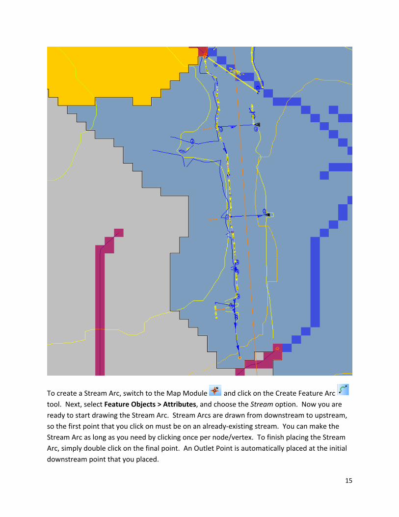
In the following screen capture, you will notice that the Drainage Area was not delineated automatically. We can create Stream Arcs to help delineate the area and also keep the boundary along the ditch. When creating Stream Arcs, the first point you click becomes an Outlet Point; therefore, they are created from downstream, to upstream (it flows the opposite way from how they are drawn). Start by using cross drains at the first points, and then follow the ditch flows. You must leave a small gap between Stream Arcs that flow in different directions. Once you have the area near the Fill/Ditch bounded by Stream Arcs, then you are ready to manually delineate the Drainage Basin. Here is a screen shot of the area:
[Type text] [Type text] [Type text]
15
To create a Stream Arc, switch to the Map Module and click on the Create Feature Arc tool. Next, select Feature Objects > Attributes, and choose the Stream option. Now you are ready to start drawing the Stream Arc. Stream Arcs are drawn from downstream to upstream, so the first point that you click on must be on an already-existing stream. You can make the Stream Arc as long as you need by clicking once per node/vertex. To finish placing the Stream Arc, simply double click on the final point. An Outlet Point is automatically placed at the initial downstream point that you placed.
[Type text] [Type text] [Type text]
16
If you need to delete an improperly placed Stream Arc, simply click the Select Feature
Point/Node button , select the Outlet Point that was automatically was placed on the
Stream Arc, and then click the Delete button . Unfortunately, there is no “undo” button.
NOTE: Sometimes you might have some Outlet Points/Nodes that for some reason were not
properly deleted. There are 2 methods to help remove these. First, go to the Map Module , and then use the command Feature Objects > Remove Orphaned Nodes. If this does not work,
then (staying in the Map Module) click the Select Feature Point/Node button , then select Feature Objects > Attributes, and choose the Generic option. You should then be able to delete the Outlet.
To place a second stream arc at the same Outlet location as another, simply click on the Outlet point as the first point of the new stream arc. This is useful when modeling two ditches that converge at the same inlet point on a drainage structure.
To delineate this new area:
1. Switch to the Drainage Module .2. Select DEM > Define Basins3. Select DEM > Basins->Polygons4. Select DEM > Compute Basin Data5. Select OK
You will notice that several boundaries were created, and also that they still slightly encroach onto the proposed roadway. Don’t worry about getting an exact area because you can easily change these areas in Microstation to more accurately be bound by the ditches. WMS uses square DEM flow cells to calculate flows, and that is why it looks so blocky. WMS is used to quickly determine rough drainage areas. Here is what the final delineation looks like, prior to smoothing it:

[Type text] [Type text] [Type text]
17
[Type text] [Type text] [Type text]
18
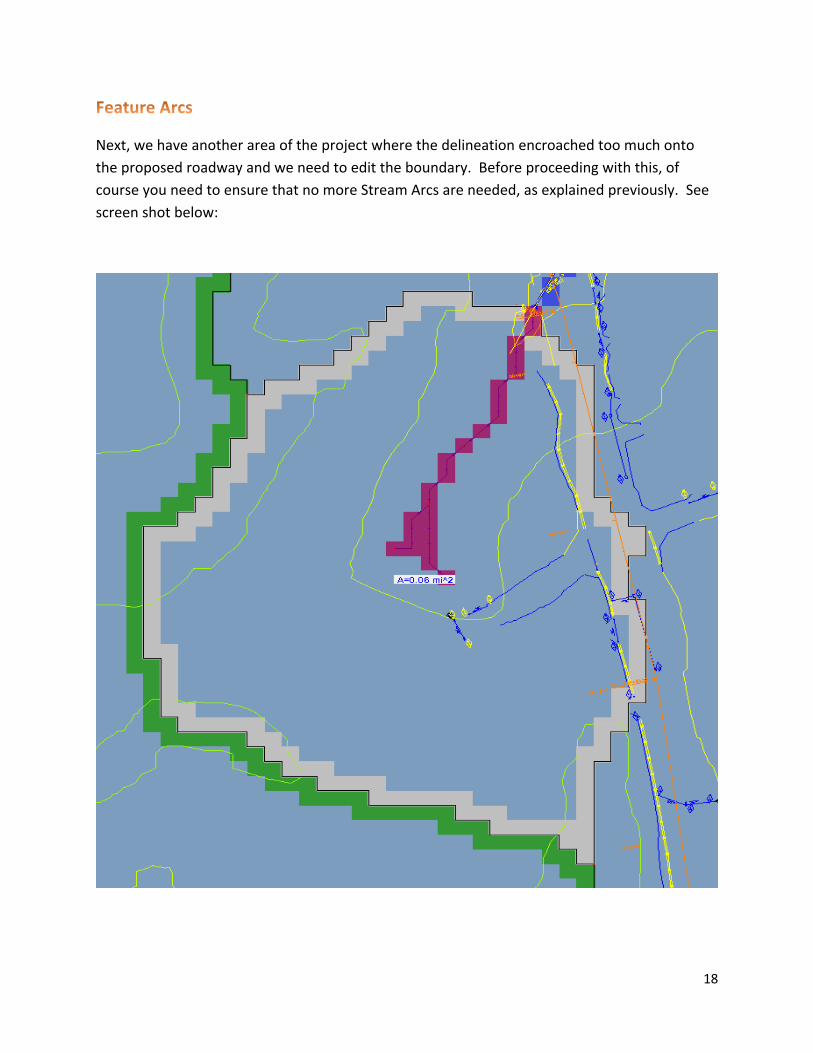
Feature Arcs
Next, we have another area of the project where the delineation encroached too much onto the proposed roadway and we need to edit the boundary. Before proceeding with this, of course you need to ensure that no more Stream Arcs are needed, as explained previously. See screen shot below:

[Type text] [Type text] [Type text]
19
To edit this boundary, click on the Select Feature Vertex button while in the Map Module. Then, simply click on any point/vertex of the Drainage Area boundary to edit it. You can drag and move the point wherever you desire, or you can delete it (by hitting the delete button in WMS or on the keyboard).
NOTE: Once you edit any existing Features/Streams or manually create any new ones, you must not use the Hydrologic Modeling Wizard. If you do, you will have deleted all of your manual work. The Wizard deletes all existing feature data except the outlet points when you click the Delineate button, although you will receive a warning message before it does so. Also, the Define Basins command is also off limits, as it will revert to your original, unedited basin boundaries.
In the above example, after editing the boundary to match more closely with the ditch, we will have to manually update the delineation. To do this:
1. Stay in the Map Module .2. Right-click on the Drainage Coverage in the Project Explorer and choose Build Polygon.3. Select OK to use all arcs.4. Right-click on the DEM under the Terrain Data in the Project Explorer and choose
Displace Options.5. In the DEM tab, toggle off the Fill Basin Boundary Only option and click OK.
6. Switch over to the Drainage Module .7. Select DEM > Polygon Basin IDs -> DEM8. Select DEM > Compute Basin Data (this command may take a while) and click OK.9. You may receive some messages that “basin edges were encountered”. This is normal
because you have manually manipulated the boundary. Simply click OK when these appear.
You will see on the following screen capture that since the polygons that make up the area are square blocks (i.e. DEM flow accumulation cells), the Drainage Basin does not exactly follow the new border. However, it is a lot closer to the true Drainage Basin of the proposed design than the automatically-generated basin. Also, as explained earlier, you can quickly and easily modify these areas in Microstation after exporting them from WMS, in order to obtain a more accurate basin size.

[Type text] [Type text] [Type text]
20
[Type text] [Type text] [Type text]
21
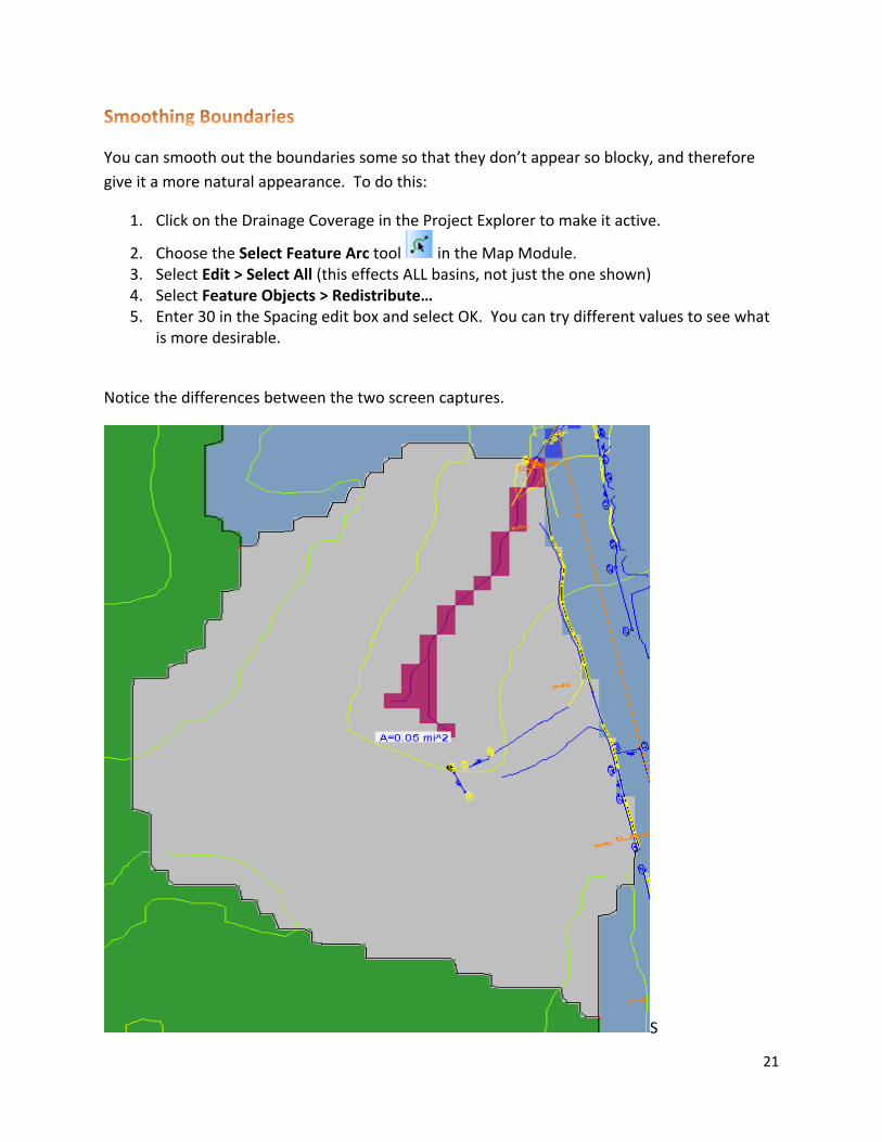
Smoothing Boundaries
You can smooth out the boundaries some so that they don’t appear so blocky, and therefore give it a more natural appearance. To do this:
1. Click on the Drainage Coverage in the Project Explorer to make it active.
2. Choose the Select Feature Arc tool in the Map Module.3. Select Edit > Select All (this effects ALL basins, not just the one shown)4. Select Feature Objects > Redistribute…5. Enter 30 in the Spacing edit box and select OK. You can try different values to see what
is more desirable.
Notice the differences between the two screen captures.
S

[Type text] [Type text] [Type text]
22
Exporting Drainage Area Boundaries
To export these Drainage Areas to Microstation:
1. Switch to the Map Module .2. Click File > Save As…3. In the “Save as type:” pull-down, choose the Shapefiles (*.shp) option.4. Type a file name (i.e. Drainage Areas) and click Save.5. In Microstation, open your project’s PI#DRNG.DGN file and turn off all levels. Also, turn
off the display of all of your current Reference files. Nothing should be displaying.6. Reference this new Shapefile created in Step 4. You will need to first change the “Files
of type:” pull-down to Shapefiles (*.shp) in order to be able to select this file.7. You should now see the Drainage Areas clearly, in the correct location. To verify the
Drainage Areas are in the correct location, turn on some levels as a reference. Once verified, turn those levels back off, leaving only the Drainage Areas.
8. Once you are satisfied with both the location and level, select the Drainage Area Reference File, right-click, and choose “Merge Into Master”. Click anywhere in the view window where you are working and choose OK if you see an ‘Alert’ window pop up.
9. All of the Drainage Areas will initially be the same level and color (white), but you must change them to match the current Electronic Data Guidelines (EDG). If you do not ensure the settings match the EDG, you will encounter problems later on when plotting.
10. Select all of the Drainage Areas (by Fence) and change their levels to what the most current EDG specifies. Currently, this level name is: DRNG_P_BASIN-Boundary-Major-Line.
You may also edit these areas however you like, as they are shapes. For example, you could edit the areas near the ditches in the previous section so that they are exactly where the ditches are, by simply moving the vertices as needed.