supporting virtualisation management - ljmu...
TRANSCRIPT

~ i ~
Supporting Virtualisation Management through an
Object Mapping Declarative Language Framework
Glyn David Hughes
A thesis submitted in partial fulfilment of the
requirements of Liverpool John Moores University
for the degree of Master of Philosophy
February 2017
~ ii ~
Abstract
Due to the inevitably vast scale of virtualised cloud computing systems, management of the numerous physical and virtual
components that make up their underlying infrastructure may become unwieldy. Many software packages that have historically
been installed on desktops / workstations for years are slowly but surely being ported to cloud computing. The virtualisation
management problems that are apparent today are only set to worsen as cloud computing systems become ever more
pervasive.
Backing cloud computing systems are equally elaborate database systems, many platforms of which have made extensive use
of distributed computing and virtualisation for years. The more recent emergence of virtualised big data systems with similarly
vast scale problems has escalated the urgent requirement for creative management of the numerous physical and virtual
components.
The thesis will initially synopsise previous investigatory research concerning these emerging problems and studies the current
disposition of virtualisation management including the associated concepts, strategies and technologies. The thesis then
continues, to describe the structure and operation of an object mapping declarative language to support the management of
these numerous physical and virtual components. The ultimate aim is to develop a Virtualisation Management System (VMS), a
software framework that is fully extensible in nature and which combines the rich capability of an imperative assembly with the
concise simplicity of a declarative language.
It is through this declarative language that human interaction and decision making may be richly yet concisely specified before
being converted through object mapping to the comparable imperative assembly for execution. It is also through parsing this
declarative language that autonomic algorithms may be able to integrate with and operate the VMS through a suitably defined
plug-in based mechanism.
The thesis will ultimately demonstrate via scenarios both basic and complex that the VMS is able to specify, observe, regulate
and adapt its virtualisation management domain to the changing disposition of the numerous physical and virtual components
that constitute cloud computing and big data systems.
~ iii ~
Acknowledgments
Directors of Study :
Dr. Dhiya Al-Jumeily - Liverpool John Moores University
Dr. Abir Hussain - Liverpool John Moores University
~ iv ~
Table of Contents
Abstract ii
Acknowledgments iii
Table of Contents iv
Table of Figures viii
Glossary of Terms ix
List of Publications xi
Chapter One ~ Introduction 1
1.1. Overview 1
1.2. Motivation 1
1.3. Research & Development Question 2
1.4. Aims & Objectives 2
1.5. Contributions to Knowledge 2
1.6. Research & Development Activity 3
1.6.1. Ethical Considerations 4
1.7. Thesis Structure 5
Chapter Two ~ Cloud Computing 7
2.1. Overview 7
2.2. Principle Architecture & Underlying Technology 8
2.3. Service Models 9
2.3.1. SaaS (Software as a Service) 9
2.3.2. PaaS (Platform as a Service) 9
2.3.3. IaaS (Infrastructure as a Service) 10
2.4. Cloud Computing’s Positioning 10
2.5. Relationship with Virtualisation 10
2.5.1. The Management Problem 11
2.6. Summary 11
Chapter Three ~ Big Data 12
3.1. Overview 12
3.2. Technology Stack 13
3.2.1. OLTP 13
3.2.2. ETL 14
3.2.3. OLAP 14
3.2.4. Data Analytics 15
3.2.5. Reporting & Visualisation 15
~ v ~
3.2.6. Bespoke Big Data Applications 15
3.3. Relationship with Virtualisation 16
3.3.1. The Management Problem 16
3.4. Summary 17
Chapter Four ~ Virtualisation 18
4.1. Overview 18
4.2. Types of Hypervisors 18
4.3. History of Hypervisors 19
4.4. Hypervisor Technology 19
4.4.1. Type-One (Native Hypervisors) 20
4.4.2. Type-Two (Hosted Hypervisors) 20
4.5. Operation of Hypervisors (Hyper-V Case Study) 21
4.5.1. Partitions 22
4.5.2. VSP (Virtualization Service Providers) & VSC (Virtualization Service Clients) 23
4.5.3. VMBus 23
4.5.4. Virtual Machine Management Service 23
4.5.5. Virtual Machine Worker Process 23
4.6. Management of Hypervisors (Hyper-V Case Study) 23
4.7. Summary 25
Chapter Five ~ Programming Paradigms 26
5.1. Overview 26
5.2. Programming Language Design 26
5.2.1. Expressivity 26
5.2.2. Abstraction 26
5.2.3. Inheritance & Polymorphism 27
5.2.4. Portability 27
5.2.5. Exception Handling 27
5.3. The Imperative Language 28
5.4. The Declarative Language 28
5.4.1. Object Mapping 29
5.4.2. Attribute Oriented Programming 31
5.5. The Multi-Paradigm Language 33
5.6. Summary 34
Chapter Six ~ Framework Requirements 35
6.1. Overview 35
6.2. Operating Requirements 35
~ vi ~
6.3. Human Interaction & Automatic / Autonomic Support 36
6.4. Summary 37
Chapter Seven ~ Framework Design 38
7.1. Overview 38
7.2. Physical Architecture 38
7.3. Software Components 39
7.4. Object Model 41
7.5. Operating Principle 42
7.5.1. Scheduling with System Agent 45
7.6. Object Mapping Declarative Language 45
7.6.1. Key / Value vs Property 49
7.6.2. Pre-Set Defaults 49
7.7. Summary 51
Chapter Eight ~ Verification & Validation 52
8.1. Overview 52
8.2. Types of Scenario 52
8.3. Scenario One (Problem & Solution) 52
8.4. Scenario Two (Problem & Solution) 56
8.5. Hypervisor Interaction 61
8.5.1. Default System Image Repository 62
8.5.2. Package Deployment 62
8.6. Human Interaction 62
8.6.1. Management DashBoard 64
8.6.2. Supporting the DashBoard 65
8.7. Immediate Limitations 66
8.8. Automatic / Autonomic Support 67
8.9. Summary 68
Chapter Nine ~ Conclusions & Future Work 69
9.1. Overview 69
9.2. Aims & Objectives Accomplished 69
9.3. Contributions to Knowledge 70
9.4. Research & Development Constraints 71
9.4.1. Access only to Local Servers 71
9.4.2. Long Term Data Storage / Archiving 71
9.4.3. Exception Handling 71
9.5. Future Work 71
~ vii ~
9.5.1. Autonomic Capability 72
9.5.2. Interoperability 72
9.5.3. Visualisation 72
9.6. Concluding Remarks 73
References 74
~ viii ~
Table of Figures
Figure 1.1 - Research & Development Map 4
Figure 2.1 - Cloud Computing Principle Architecture 8
Figure 3.1 - Big Data Technology Stack 13
Figure 4.1 - Hypervisor Technology 20
Figure 4.2 - Hyper-V Technology Stack 22
Figure 5.1 - Imperative Language Syntax 28
Figure 5.2 - Declarative Language Syntax 28
Figure 5.3 - Very Simple C# Objects 30
Figure 5.4 - Instantiating Objects Imperatively (using C#) 31
Figure 5.5 - Instantiating Objects Declaratively (using XAML) 31
Figure 5.6 - Declaring Custom Attribute Class 32
Figure 5.7 - Reflecting Custom Attribute Class 33
Figure 7.1 - Virtualisation Management System Physical Architecture 38
Figure 7.2 - Virtualisation Management System UML Component Diagram 40
Figure 7.3 - Virtualisation Management System Object Model Diagram 41
Figure 7.4 - Virtualisation Management System Control Flow Diagram 43
Figure 7.5 - Virtualisation Management System Interface, Class & Enumeration Definitions 47
Figure 7.6 - Virtualisation Management System Imperative Syntax (using C#) 48
Figure 7.7 - Virtualisation Management System Declarative Syntax (using XAML) 49
Figure 8.1 - Virtualisation Management System Scenario Resolutions 52
Figure 8.2 - Virtualisation Management System Scenario One’s Original XAML 53
Figure 8.3 - Virtualisation Management System Scenario One’s Revised XAML 55
Figure 8.4 - Virtualisation Management System Scenario Two’s Original XAML 57
Figure 8.5 - Virtualisation Management System Scenario Two’s System Agent XAML 58
Figure 8.6 - Virtualisation Management System Scenario Two’s Revised XAML 60
Figure 8.7 - Basic DashBoard Scenario Graphical User Interface 63
Figure 8.8 - Basic DashBoard Scenario Declarative Markup 64
Figure 8.9 - Virtualisation Management System C# RequestPacket Class 65
Figure 8.10 - Virtualisation Management System C# StatusPacket Class 66
Figure 9.1 - Aims & Objectives Accomplished 70
Figure 9.2 - The Very First Architecture Diagram 73

~ ix ~
Glossary of Terms
AJAX (Async. JavaScript & XML)
API (Application Programming Interface)
CCMS (Cloud Computing Management System)
CLR (Common Language Runtime)
COM (Component Object Model)
CPU (Central Processing Unit)
CSV (Comma Separated Value)
DLL (Dynamic Link Library)
ETL (Extract Transform & Load)
GUI (Graphical User Interface)
IaaS (Infrastructure as a Service)
IDE (Integrated Development Environment)
IIS (Internet Information Services)
I/O (Input/Output)
JSON (JavaScript Object Notation)
MMC (Microsoft Management Console)
MVC (Model View Controller)
NFS (Network File System)
OLAP (Online Analytical Processing)
OLTP (Online Transaction Processing)
PaaS (Platform as a Service)
QoS (Quality of Service)
RDBMS (Relational Database Management System)
RDP (Remote Desktop Protocol)
RESTful (Representational State Transfer)
SaaS (Software as a Service)
SQL (Structured Query Language)
UML (Unified Modelling Language)
VDev (Virtual Devices)
VMM (Virtual Machine Manager)
VMMS (Virtual Machine Management Service)
VMWP (Virtual Machine Worker Process)
VSC (Virtualization Service Clients)
~ x ~
VSP (Virtualization Service Providers)
WCF (Windows Communication Foundation)
WMI (Windows Management Instrumentation)
WPF (Windows Presentation Foundation)
XAML (eXtensible Application Markup Language)
XML (eXtensible Markup Language)
~ xi ~
List of Publications
This research and development has been documented, in part, within the following publications :
G.D. Hughes, D. Al-Jumeily, A.J. Hussain, “Research, Design & Development Review of the Cloud Computing
Management System (CCMS)”, 6th International Conference for Internet Technology & Secured Transactions (ICITST
2011), ISBN : 978-1-4577-0884-8, Abu Dhabi, UAE, 2011.
G.D. Hughes, D. Al-Jumeily, A.J. Hussain, “Supporting Cloud Computing Management through an Object Mapping
Declarative Language”, 3rd International Conference on Developments in eSystems Engineering (DeSE 2010), ISBN :
978-0-7695-4160-0, London, UK, 2010.
G.D. Hughes, D. Al-Jumeily, A.J. Hussain, “A Declarative Language Framework for Cloud Computing Management”, 2nd
International Conference on Developments in eSystems Engineering (DeSE 2009), ISBN 978-0-7695-3912-6, Abu Dhabi,
UAE, 2009.

~ 1 ~
Chapter One ~ Introduction
1.1. Overview
In any complex computing system there are, amongst others, two accompanying mechanisms, a management sub-
system and an underlying programmatic framework. Virtualisation is a cogent example of such a complex computing
system. Virtualisation may be employed in small scale desktop environments, but it is also frequently scaled to hugely
complex data centre infrastructure. In such a scenario, there may be hundreds or thousands of components and sub-
components and as such, a comprehensible requirement for effective and efficient management sub-systems.
Supporting such management sub-systems are typically programmatic frameworks, ranging from low level to high
level Application Programming Interfaces (APIs). Any proprietary management tools are typically designed atop these
APIs while third-party developers may access the programmatic frameworks to develop bespoke applications and
services. Alongside developers there are also, with growing frequency, automatic / autonomic systems that strive to
augment or replace human interaction.
When designing APIs to support both humans and automatic / autonomic systems there is a desire to provide a
readily understandable programmatic environment. With the complexity inherent in utilizing an imperative language
there are considerable advantages to be gained in utilizing a more declarative language, especially as object mapping
allows both humans and automatic / autonomic systems to specify considerable amounts of syntactically complete,
object oriented, imperative code without actually writing any imperative code.
1.2. Motivation
The evolution of the internet into an application and service oriented platform has resulted in the growth of cloud
computing as well as the underlying data centre infrastructure. The use of virtualisation in hugely complex data centre
infrastructure has seen comparable growth and today there are few physical servers directly hosting cloud computing
applications and services, they are now wholly virtualised!
Similarly, the evolution of the database from the relatively light weight Relational Database Management System
(RDBMS) through data warehousing to hugely complex, bespoke big data applications has placed differing yet no less
demanding requirements on the use of virtualisation in hugely complex data centre infrastructure.
While the problem of managing virtualisation technology is relatively new, there are historical parallels in any
complex infrastructure. A cogent example can be found in an electricity grid, where power is not only produced,
distributed and consumed, but the amount of power required, by whom and where is tracked, analysed and used to
anticipate and thusly balance future supply and demand.
~ 2 ~
The same management problems are now directly relevant to virtualisation technology as the enormous material and
running costs of hugely complex data centre infrastructure along with global initiatives in green computing require that
hardware and software resources be effectively and efficiently managed.
1.3. Research & Development Question
Motivated by these issues, the key research and development question that this thesis will attempt to address is as
follows (in the author’s original wording), “Can an object mapping declarative language framework effectively and
efficiently facilitate both humans and autonomic systems in the setup and management of virtualised systems, their
resources and their infrastructure?”
1.4. Aims & Objectives
The aims of this study are to design, develop and verify a framework that supports virtualisation management using
an object mapping declarative language to store the system schema in play at any specific moment. The declarative
language should form the interface between the framework and both humans and automatic / autonomic systems and
it should express its functionality through an underlying imperative language.
To help achieve these aims, the objectives of this study are as follows :
1. Explore key computing infrastructure that rely heavily on virtualisation technology.
2. Investigate virtualisation technology in terms of its functionality and management.
3. Investigate programming paradigms that may serve to satisfy the anticipated development to come.
4. Design and implement a programming framework that satisfies the framework
requirements using the appropriate programming paradigms.
5. Verify the framework in terms of its ability to effectively and efficiently manage the key computing infrastructure.
1.5. Contributions to Knowledge
The customary use of an object mapping declarative language has been within Graphical User Interface (GUI)
designers whereby a declarative language, such as eXtensible Markup Language (XML), is stubbed out by the designers
following a drag and drop GUI design session. A one-to-one relationship persists between the declarative language and
its visual equivalent in the designers and the declarative language can be thought of as the designers default data
storage format.
~ 3 ~
The story doesn’t end their though as the very same declarative language can also have a one-to-one relationship
with an imperative assembly, typically object oriented in nature. Indeed, one of the key characteristics of the object
oriented paradigm is the concept of composition, allowing any type to be embedded within others. A declarative (XML
alike) language uses a nested hierarchy structure to embed elements within others in much the same way. So much so
that an imperative assembly may be specified entirely using a declarative language, a mechanism known as object
mapping.
This results in an interesting situation in which designers and developers can now specify considerable amounts of
syntactically complete, object oriented, imperative code without actually writing any imperative code. This allows
problem solving the problem domain to remain at the forefront without the distractions inherent in boilerplate coding,
typically much more of an issue when working with imperative code.
The key contributions to knowledge can thusly be summarised as follows :
1. Encapsulating the key virtualisation management operations in a readily extensible imperative framework.
2. Exposing the imperative framework’s capability through a declarative language.
3. Providing a mechanism by which both humans and automatic / autonomic systems may employ
the declarative language interactively.
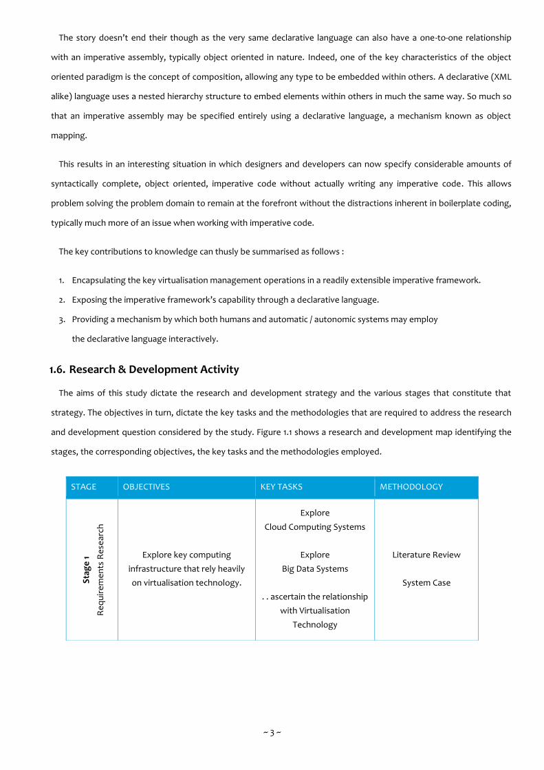
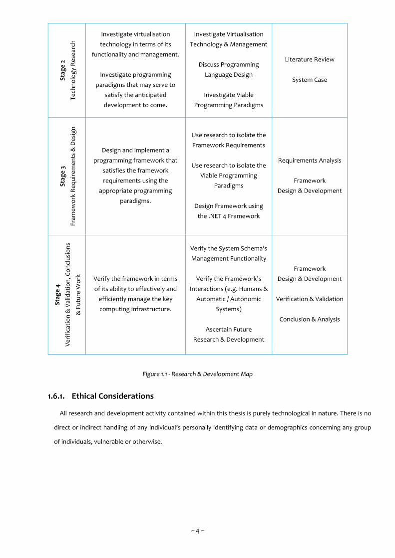
1.6. Research & Development Activity
The aims of this study dictate the research and development strategy and the various stages that constitute that
strategy. The objectives in turn, dictate the key tasks and the methodologies that are required to address the research
and development question considered by the study. Figure 1.1 shows a research and development map identifying the
stages, the corresponding objectives, the key tasks and the methodologies employed.
STAGE OBJECTIVES KEY TASKS METHODOLOGY
Sta
ge
1
Re
qu
ire
me
nts
Re
sear
ch
Explore key computing
infrastructure that rely heavily
on virtualisation technology.
Explore
Cloud Computing Systems
Explore
Big Data Systems
. . ascertain the relationship
with Virtualisation
Technology
Literature Review
System Case
~ 4 ~
Figure 1.1 - Research & Development Map
1.6.1. Ethical Considerations
All research and development activity contained within this thesis is purely technological in nature. There is no
direct or indirect handling of any individual’s personally identifying data or demographics concerning any group
of individuals, vulnerable or otherwise.
Sta
ge
2
Te
chn
olo
gy
Re
sear
ch
Investigate virtualisation
technology in terms of its
functionality and management.
Investigate programming
paradigms that may serve to
satisfy the anticipated
development to come.
Investigate Virtualisation
Technology & Management
Discuss Programming
Language Design
Investigate Viable
Programming Paradigms
Literature Review
System Case
Sta
ge
3
Fram
ew
ork
Re
qu
ire
me
nts
& D
esi
gn
Design and implement a
programming framework that
satisfies the framework
requirements using the
appropriate programming
paradigms.
Use research to isolate the
Framework Requirements
Use research to isolate the
Viable Programming
Paradigms
Design Framework using
the .NET 4 Framework
Requirements Analysis
Framework
Design & Development
Sta
ge
4
Ve
rifi
cati
on
& V
alid
atio
n, C
on
clu
sio
ns
& F
utu
re W
ork
Verify the framework in terms
of its ability to effectively and
efficiently manage the key
computing infrastructure.
Verify the System Schema’s
Management Functionality
Verify the Framework’s
Interactions (e.g. Humans &
Automatic / Autonomic
Systems)
Ascertain Future
Research & Development
Framework
Design & Development
Verification & Validation
Conclusion & Analysis
~ 5 ~
1.7. Thesis Structure
In terms of its chapters, the thesis’s structure follows the stages as shown in the research and development map :
Requirements Research (comprising chapters 2 & 3)
Technology Research (comprising chapters 4 & 5)
Framework Requirements & Design (comprising chapters 6 & 7)
Verification, Validation, Conclusions & Future Work (comprising chapters 8 & 9)
Chapter 2 is the first of two requirements research chapters concerned with establishing the necessity of and
requirements for virtualisation technology. The chapter contains an analysis of the characteristics that cloud computing
systems exhibit. The chapter then continues with a discussion of the principle architecture, underlying technology and
service models that existing and emerging cloud computing systems contain. As the first of two scenarios for
virtualisation, it is important to determine the requirements that are expected of virtualisation technology when
supporting cloud computing systems / infrastructure.
Chapter 3 is the second of two requirements research chapters concerned with establishing the necessity of and
requirements for virtualisation technology. The chapter contains an analysis of the concepts and characteristics that big
data systems exhibit. The chapter then continues with a discussion of the technology stack, including Online
Transaction Processing (OLTP), Extract Transform & Load (ETL), Online Analytical Processing (OLAP), Data Analytics
and Reporting & Virtualisation. As the second of two scenarios for virtualisation, big data systems / infrastructure have
somewhat differing but no less important requirements that are expected of virtualisation technology.
Chapter 4 is the first of two technology research chapters taking a comprehensive yet concise look at virtualisation
technology. The chapter examines how hypervisors actually operate as well as the existing and emerging management
mechanisms. Emerging from this knowledge, are a set of well-defined services and operations (i.e. the things that
hypervisors can actually do). It is this knowledge that will serve to inform the core functionality of the VMS.
Chapter 5 is the second of two technology research chapters that primarily concerns the relationship between the
imperative and declarative programming language. While they strive for a differing set of characteristics, internally a
declarative language can map to an imperative language. This combines the separation of concern inherent in
declarative markup with the fine grain control inherent in imperative code. The chapter then continues with a
discussion of two mechanisms that achieve this, object mapping and attribute oriented programming.
Chapter 6 combines the knowledge gained from the previous research chapters to identify the virtualisation
management operations that the VMS will need to support. The chapter will ultimately define a concise collection of
functional and non-functional requirements along with the required external interaction with both humans and
automatic / autonomic systems.
~ 6 ~
Chapter 7 is the first of two chapters that explore the VMS design and development. The chapter begins by designing
the physical architecture, software components, imperative (and by virtue, declarative) object model and operating
principle of the VMS. This chapter then continues by exampling the object mapping declarative language in situ along
with the various supporting mechanisms that allow the VMS to provide its core functionality.
Chapter 8 is the second of two chapters that explore the VMS design and development whilst concurrently verifying
and validating the VMS core functionality. The chapter aims to bring the VMS to life by way of two scenarios, with each
scenario demonstrating some core functionality as it attempts to solve specific problems that are typical of the VMS
operating domain. The chapter then continues by demonstrating the three key areas of external interaction that the
VMS supports (namely the hypervisor, the human and the automatic / autonomic plug-in) and by virtue, revealing the
key findings of VMS and identifying areas of ongoing design and development that will inform any future work.
Chapter 9 presents the research and development findings of the thesis in terms of the aims & objectives
accomplished, the contributions to knowledge, the research and the development constraints. The chapter then wraps
up the thesis with a discussion of the possible / likely future research and development concerns, with each significant
component / sub-component of the VMS containing areas that could be potentially augmented or extended.

~ 7 ~
Chapter Two ~ Cloud Computing
2.1. Overview
The term cloud computing is a moniker for a computing model that has existed for some time but is only now
evolving to the point where it is becoming commonplace. Broadly speaking, cloud computing describes a computing
model in which information technology systems are accessed purely over the internet, thusly removing the
requirement to setup software and servers locally [1] [2].
The internet based nature of cloud computing means that software becomes a service (actually, SaaS or “Software as
a Service” is a whole subset of cloud computing [3]) that may be freely available to the public or available only to a
specific group / institution. The following key characteristics are strongly representative of cloud computing :
Availability.
o The vast majority of data and processing is typically hosted server side so cloud applications can be accessed
from any device connected to the internet. In addition the level of redundancy that cloud computing brings
across applications, servers and data centres ensure that cloud applications are always online [3].
Scalability.
o Every cloud application can be hosted alongside numerous others in centralized servers and data centres. By
automatically provisioning and sharing resources, such as processing, memory and bandwidth, a data centre’s
resources can by optimized to respond to and even anticipate peak working periods [4].
Security.
o The security of user’s data is typically more elaborately protected due to the centralization of data within
servers and data centres that have hive like security concerns beyond those of any individual cloud
applications and of any less centralized, locally hosted applications [3].
Maintenance.
o Depending on the specific role of cloud applications, there is likely to be little or no maintenance activity
expected of users. Any such maintenance activity is the responsibility of the owners of the data centre and is
typically rolled in to the data centre’s service level agreement [4].
Performance.
o In much same way scalability can be achieved through optimizing a data centre’s resources, so too can the
outright performance of cloud applications [4]. In addition, a data centre by its very nature will be capable of
considerably more processing than any servers that host locally.
~ 8 ~
Costs.
o The costs to users may be reduced as cloud computing providers operate the entire architecture and users
need only have access to said architecture via the internet [3]. Costs at most are restricted to service
subscriptions, which are frequently known under the umbrella term, utility computing [5].
2.2. Principle Architecture & Underlying Technology
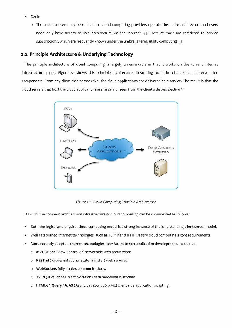
The principle architecture of cloud computing is largely unremarkable in that it works on the current internet
infrastructure [1] [6]. Figure 2.1 shows this principle architecture, illustrating both the client side and server side
components. From any client side perspective, the cloud applications are delivered as a service. The result is that the
cloud servers that host the cloud applications are largely unseen from the client side perspective [3].
Figure 2.1 - Cloud Computing Principle Architecture
As such, the common architectural infrastructure of cloud computing can be summarised as follows :
Both the logical and physical cloud computing model is a strong instance of the long standing client server model.
Well established internet technologies, such as TCP/IP and HTTP, satisfy cloud computing’s core requirements.
More recently adopted internet technologies now facilitate rich application development, including :
o MVC (Model View Controller) server side web applications.
o RESTful (Representational State Transfer) web services.
o WebSockets fully duplex communications.
o JSON (JavaScript Object Notation) data modelling & storage.
o HTML5 / jQuery / AJAX (Async. JavaScript & XML) client side application scripting.

~ 9 ~
The novel aspects of cloud computing revolve around scalability and include revised usage patterns concerning both
the hardware and software components [6]. Every cloud application is hosted in centralized data centres that provide
high performance processing, redundancy through hardware clustering and multiple backbone internet connections,
high availability afforded by backup power supplies and the economic sustainability of sharing such resources and
capabilities [2] [7].
Within these centralized data centres, individual servers are tasked with specific roles and responsibilities including
web servers, database servers, content management servers, backup and recovery servers and the all-important
management / load balancing servers. A collection of servers may also be clustered together so as to better facilitate
the advantages as discussed in the previous paragraph [6].
2.3. Service Models
There are three generalised tiers to the capability and service that cloud computing solutions may provide. They are
tiered by virtue of their level of logical abstraction. At the top end we have the ready for market applications that, from
the client side perspective appear as any locally hosted application would in the long standing client server model. At
the bottom end we have the raw infrastructure components upon which servers, applications and services are hosted.
When these tiers are provided at costs, they are commonly called utility computing and the provision of cloud
computing services becomes subscription based [5]. The utility computing approach has the advantage of a low or even
zero initial setup costs and cloud applications distributed through utility computing are simply supplied on a “pay as
you go” basis.
2.3.1. SaaS (Software as a Service)
The SaaS model is the most significant subset of cloud computing and represents its most core principle,
which primarily concerns the high availability of applications and services that are hosted in centralized data
centres. These applications and services range from the bespoke developed variety to the commercially available
and dynamically customizable variety [3].
2.3.2. PaaS (Platform as a Service)
PaaS is an extension of the SaaS model. The PaaS model exposes a complete set of tools and controls to
support the entire software development life cycle. This takes place without the need for any development tools
to be present on the client side computer. Effectively the developers / authors writes applications on the server
side directly and PaaS manages the entire process through well-defined workflows [8].
~ 10 ~
2.3.3. IaaS (Infrastructure as a Service)
The IaaS model is simultaneously the simplest and also the most extreme form of cloud computing. It exposes
a complete computing infrastructure, typically physical servers and networks that may support applications, data
storage and virtual servers and networks [9]. The engineers have considerable autonomy in how the servers are
setup and managed.
2.4. Cloud Computing’s Positioning
There is a grey area between the long established eCommerce application and the cloud application. A cogent
example might include long standing online services such as HotMail (now Outlook.com). HotMail has always been web
based, data driven, available globally with 99% uptime, scalable to foreseeable usage requirements and it has always
been a freely available online service. So by industry standards, does it qualify as a cloud application? Probably yes, but
the genesis of HotMail’s design and development was largely solitary from other online services and only much later on
was it incorporated into the wider Microsoft Live family, which can be considered a true first generation collection of
cloud applications.
There is also a grey area concerning cloud computing infrastructure. What is the difference between a group of well-
managed, high performance servers and a data centre specifically designed to operate cloud computing solutions? As
before, the actual hardware components are typically comparable, but with the data centre simply having more
hardware resources. The most significant distinction though is that cloud computing brings with it a set of service
models that define and manage how users interact with cloud applications [1] [6].
It is thusly not unreasonable to determine that cloud applications are either designed from scratch to exist within a
cloud computing infrastructure or are scaled up versions of existing online services that may or may not have already
exhibited characteristics typical of cloud computing.
2.5. Relationship with Virtualisation
Virtualisation, in respect of cloud computing, primarily involves consolidation, whereby numerous, typically less
capable physical servers are replaced by fewer, more capable physical servers [10]. This reduces costs as less hardware
resources are required. However, it is not favourable to fully consolidate host operating systems so each must be
converted to a guest operating system. In this guise, many virtual servers can execute on a single physical server.
The commercial growth in the use of virtualisation has tightly mirrored cloud computing [7]. This is not surprising as
top level virtualisation requires the centralized deployment and management of systems and resources, a definition
that is certainly descriptive of cloud computing [10]. The SaaS model abstracts information technology in a way
comparable to the abstraction of enterprise servers and software in virtual servers [3]. Recent advances in available
hypervisors have made virtualisation very attractive to industry and most if not all cloud computing architectures are
now based on virtual servers rather than physical servers [11] [1].

~ 11 ~
2.5.1. The Management Problem
By definition, the use of virtualisation as the basis of a cloud computing architecture implies a considerable
number of virtual servers, typically many more than the physical servers upon which they execute [6]. This poses a
system and resource management problem, especially in situations where virtual servers are constantly being
instantiated, allocated work (swapping in), de-allocated work (swapping out) and then destroyed. Indeed, many
operations might be performed on a cloud computing architecture, including :
Swapping In & Swapping Out.
o Generally to distribute work during any bottlenecks or peak work periods [4].
Scaling Up & Scaling Down.
o A less aggressive case of swapping which virtual servers are allocated more resources and vice versa [4].
Redundancy & Recovery.
o To provide an always online guarantee and to ensure that service and data is readily recoverable.
Typically, cloud applications themselves are not aware of these changes [1]. This is not only wise, but also
common practice in many computing technologies; software should not normally care about the hardware
resources on which it executes. However, there is a case to allow cloud applications to specify their preferred
operating environments and to describe their own projected requirements and characteristics.
Various software vendors have developed proprietary solutions that manage cloud computing infrastructure
and more specifically the virtual servers upon which they execute. The AutoPilot system was developed internally
at Microsoft to manage the initial growth and operation of the aforementioned Microsoft Live family [12].
However, it is ostensible that the AutoPilot system focuses on top down management and thusly makes
assumptions as to the specific preferred operating environments of its cloud applications [12]. Similarly the
OpenStack AutoPilot system which is developed by Canonical alongside their flagship Ubuntu Linux operating
system has seen considerable growth as an IaaS platform [13]. However, much like Microsoft’s AutoPilot system
and a representative characteristic of an IaaS platform, there is still a focus on top down management.
2.6. Summary
This chapter began by identifying some of the key characteristics that cloud computing systems exhibit, these
characteristics would later on in the chapter serve to specify the operations that virtualisation would need to provision
in support of cloud computing systems. This chapter has also discussed the principle architecture, underlying
technology and service models that existing and emerging cloud computing systems contain and critically, these
aspects have been found to closely relate to virtualisation technology.
~ 12 ~
Chapter Three ~ Big Data
3.1. Overview
The term big data is a relatively recent moniker that refers to a set of both evolutionally and revolutionary
developments in the field of data analytics. It concerns large data sets that are so substantial in size and complexity
that traditional data processing mechanisms are inadequate. Indeed, the long established Relational Database
Management System (RDBMS) along with similarly long established data reporting and visualisation tools perform
poorly when handling big data solutions [14].
The architecture of big data solutions thusly combines both existing and emerging data mechanisms to bestow a
previously unseen ability to manage huge sets of disparate data and more importantly, to derive timely analysis that
facilitates both tactical and strategic decision making [14]. This is commonly achieved through massively parallel
processing which in turn is achieved through distributed computing environments. The following key characteristics
(colloquially known as the three V’s) are strongly representative of big data [15] :
1. Volume.
o How much data is generated and processed?
2. Velocity.
o How quickly is the data generated and how quickly must it be processed?
3. Variety.
o What is the data’s nature and its format, ranging from traditional structured data to highly un-structured data?
This is perhaps the first significant departure from the long established RDBMS, which are typically designed to
manage traditional structured data only.
These initial three V’s provide an insight into the problems of managing such huge sets of disparate data, but they
could just as easily be applied to non big data solutions. Thusly, two additional V’s have recently been defined to help
describe the hugely complex nature of big data [15] :
4. Veracity.
o How accurate is the data? Critically, the accuracy of any analysis is highly dependent on the accuracy of the
original data and any resulting calculations may become totally unviable in the presence of erroneous or
missing data.
5. Variability.
o In what ways does the meaning of the data change? Frequently confused with variety, variability is especially
problematic when dealing with natural language as meaning changes constantly due to context (e.g. serious
vs sarcastic statements).
~ 13 ~
While it may be convenient to classify big data using these characteristics, they can be frequently misleading and
overly simplistic (e.g. big data solutions may involve huge volumes of traditional structured data or they may involve a
tiny amount of highly un-structured data and while both are complex problems, they require quite distinct solutions)
[14].
3.2. Technology Stack
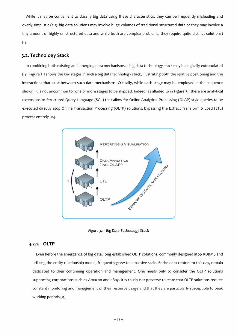
In combining both existing and emerging data mechanisms, a big data technology stack may be logically extrapolated
[14]. Figure 3.1 shows the key stages in such a big data technology stack, illustrating both the relative positioning and the
interactions that exist between such data mechanisms. Critically, while each stage may be employed in the sequence
shown, it is not uncommon for one or more stages to be skipped. Indeed, as alluded to in Figure 3.1 there are analytical
extensions to Structured Query Language (SQL) that allow for Online Analytical Processing (OLAP) style queries to be
executed directly atop Online Transaction Processing (OLTP) solutions, bypassing the Extract Transform & Load (ETL)
process entirely [16].
Figure 3.1 - Big Data Technology Stack
3.2.1. OLTP
Even before the emergence of big data, long established OLTP solutions, commonly designed atop RDBMS and
utilizing the entity relationship model, frequently grew to a massive scale. Entire data centres to this day, remain
dedicated to their continuing operation and management. One needs only to consider the OLTP solutions
supporting corporations such as Amazon and eBay. It is thusly not perverse to state that OLTP solutions require
constant monitoring and management of their resource usage and that they are particularly susceptible to peak
working periods [17].

~ 14 ~
Given this systemic knowledge, OLTP is a suitable case for virtualisation on its own. But, in the context of big
data, OLTP represents one of the primary data sources and thusly helps form the first stage in the big data
technology stack.
3.2.2. ETL
The ETL process is the primary mechanism by which a data warehouse is initially constructed. Additionally, the
process is typically re-run on a schedule such as weekly, quarterly, annually, so as to populate the data warehouse
with any newly available data [18].
The process begins with the extraction of data from one or more data sources such as RDBMS, SpreadSheets,
Plain Text and Comma Separated Value (CSV). Next, the transformation of data ensures that it conforms to a
single structure without losing any of its underlying semantics. Finally, the loading of data into the data
warehouse though an appropriate analytical data model (e.g. the multi-dimensional vs the tabular model).
Critically, each of these three stages are distinct and may take considerable processing, memory and data
storage, so it is common for suitably designed work flows to execute the three stages concurrently. This allows
data to progress from one stage to the next as a stream without having to wait for the entire block of data to
pass through the previous stage [18].
Thusly, in the context of a big data, ETL represents the transition of data from data sources to data warehouses
and thusly helps form the second stage in the big data technology stack.
3.2.3. OLAP
As with OLTP, long established OLAP solutions also pre-date big data. Based around the data warehouse and
primarily utilizing the multi-dimensional model, the role of OLAP is quite distinct from OLTP. Whereas the entity
relationship model is designed to minimize data redundancy and support large numbers of relatively tiny but
concurrent transactions, the multi-dimensional model is designed to process large amounts of data in lengthy
transactions to which only a few users have access rights [19]. These users are typically business executives who
use OLAP to inform in strategy and planning decisions.
As much of the work performed by OLAP is concerned with aggregating data when the ETL process must
populate the data warehouse with any newly available, it is not perverse to state that OLAP solutions experience
periods of relatively low resource usage and only on a set schedule, do they suddenly require extra processing,
memory and data storage [19].
~ 15 ~
3.2.4. Data Analytics
One emerging distinction between OLAP and data analytics is the extension of access rights to users who are
non-business executive. With data analytics, users who work on tactical rather than strategic decision making
may leverage real-time analysis to inform business operations within their operational area. In this way, data
analytics can be seen to move historically back office processing to the front office [20]. Many corporate business
applications, such as Microsoft Excel, are rapidly incorporating the client side functionality necessary to interact
with data analytics. In addition the field of data analytics has grown to the point where it may effectively envelop
OLAP [21].
3.2.5. Reporting & Visualisation
The developer’s interface to a database solution (be it OLTP or OLAP) is typically complex and not in any way
friendly to non-technical users. To enable such users to view data in a logical and concise way, data reporting
systems exist that provide simple operations, such as filtering and sorting, along with results displayed in tables
and graphs. While these systems have been deployed alongside database solutions for a long time, they may also
be employed in displaying results from data analytics solutions [22].
As the complexity of data grows, so too does the necessity to view data effectively. Visualisation is an emerging
technology that offers a more interactive, animation oriented interface than data reporting systems. They are
typically designed atop dedicated visualisation Application Programming Interfaces (APIs) or even fully
established 3D APIs such as OpenGL and DirectX [23]. These APIs are of special interest as they may require an
additional virtualisation technology, that of graphics virtualisation.
3.2.6. Bespoke Big Data Applications
Using the big data technology stack as shown in Figure 3.1 we can see that bespoke big data applications are
pervasive across every key stage. As an emerging technology, big data is highly dynamic and defining its scope
may be unproductive. Thusly, any big data applications are likely to have been designed and developed to
bespoke requirements.
Any big data solution can also be thought of as being horizontally or vertically aligned in scope when
considering the big data technology stack. A horizontally aligned solution would likely focus in depth on fewer
stages (e.g. taking the results from the reporting & visualisation stage). In contrast, a vertically aligned solution
would likely interact with more stages but perhaps not in as much depth (e.g. taking only pertinent data from
each stage).

~ 16 ~
3.3. Relationship with Virtualisation
Many of the key stages as shown in Figure 3.1 are implemented by the big three’s (e.g. Oracle, IBM & Microsoft)
flagship enterprise servers. When taking Microsoft as an example, the SQL Server platform supports OLTP, ETL, OLAP &
Reporting. The newly acquired R Server platform performs data analytics and visualisation with bespoke big data
applications on the platform’s immediate road map. For years now Microsoft has closely tied their enterprise servers
with their server operating system’s native capabilities, including technologies such as Always-On Failover Clustering
[24]. Always-On requires multiple instances of the enterprise servers to be hosted in a distributed environment typically
designed atop virtual servers. In such a scenario, enterprise servers are not only ideally suited to virtualisation
technology but in fact desire it.
In much the same way that most if not all cloud computing architectures are now based on virtual servers rather than
physical servers, the same can said for big data architectures. Staying with Microsoft as an example, the growth of
Azure has been astonishing and every enterprise server that Microsoft offers now has some degree of Azure
integration. Azure in turn, is almost entirely based on Microsoft’s own virtualisation platform, known as Hyper-V. Thusly
whenever big data architectures are running atop Azure, they are by definition running atop virtual servers.
3.3.1. The Management Problem
As discussed in Section 3.1, processing large data sets, be they structured or un-structured is inherently
preferable through distributed computing environments. As such, the processing tasks of big data solutions (e.g.
capture, organise, integrate, analyse & act) are typically processed independently yet in parallel [25]. MapReduce
processing is a cogent example of this scenario; as the Map and Reduce processes are independent, they can
allowed to compete constructively for resources depending on the processing payloads each has at any one time
and the current level of contention amongst the hosting virtual servers [25]. Virtualisation technology thusly
bestows big data solutions with the ability to scale dynamically to unexpected payloads no matter which tasks
may trigger the payload. Despite processing occurring independently yet in parallel, there are some work flow
considerations in big data architecture, including :
Scheduling.
o Be it a schedule defined by users, as is the case with the loading of data in ETL or a wholly automated
schedule, as is typically the case with the optimization and aggregation in OLAP.
Prioritising.
o With such huge sets of data being processed, there are logically going to be subsets of data that must be
processed first, either to support follow on data processing or to answer more urgent queries as posed
by users.
~ 17 ~
3.4. Summary
Mirroring the previous chapter, this chapter began by identifying some of the key characteristics that big data
systems exhibit, these characteristics would later on in the chapter serve to specify the operations that virtualisation
would need to provision in support of big data systems. This chapter has also discussed the technology stack,
identifying the key stages that existing and emerging big data systems contain and critically, as with the previous
chapter, these aspects have been found to closely relate to virtualisation technology.
~ 18 ~
Chapter Four ~ Virtualisation
4.1. Overview
The previous two chapters have established the positioning of virtualisation as one of the key technologies employed
in both cloud computing and big data solutions. Following a general discussion of the various types of virtualisation
that are available, this chapter moves on to catalogue the history of hypervisors and explore the concepts that
underpin the technology before concluding with a case study into one of the most common hypervisors in industry
today along with an investigation into the existing and emerging management mechanisms.
4.2. Types of Hypervisors
There are various types of virtualisation available with some representing the high level or primary layers and some
representing the nested or secondary layers. While it is both undesirable and unnecessary to describe every single type,
the following are representative of the primary layers :
Hardware Virtualization.
o Allows multiple operating systems to run on the same physical machine at the same time. The physical
machine is logically partitioned into multiple virtual machines and any hardware resources, such as memory
and processing, are shared between them. The virtual machines are thusly software representations of the
physical machine, yet they are able to perform the same tasks [11] [26].
Application Virtualisation.
o Allows for an application to be encapsulated inside its own miniature operating system “bubble” and then
deployed to a target operating system without any notion as to the runtime environment of that operating
system. A cogent example of application virtualisation is the Wine Platform which allows Windows
applications to run on Linux without necessarily being in any way aware [27]. An application virtualisation
platform must thusly replace some or all of the target operating system’s runtime environment and is
responsible for translating any Input/Output (I/O) requests that the encapsulated application might make [11]
[26].
Storage Virtualisation.
o Serves to combine physical storage resources into a single logical storage resource. Any applications accessing
the virtualised storage have no notion of how and where the data is actually stored and retrieved [26] [28]. A
cogent example of storage virtualisation is the Network File System (NFS) which may encapsulate physical
storage resources from disparate and even incompatible platforms (e.g. the native file systems of Windows
and Linux, NTFS and EXT4 respectively).
~ 19 ~
Network Virtualisation.
o A physical network may be virtualised in much the same way a physical machine may be and in data centres,
both networks and machines are typically virtualised together in one operating environment. There are two
general forms of network virtualisation, external and internal. External describes a scenario in which one or
more physical networks are encapsulated then partitioned into as many logical networks as are required [29].
Internal describes a scenario in which a single physical machine may host one or more wholly software driven
networks, typically to create a virtualised network between the guest operating systems that are running on
the host operating system [29].
4.3. History of Hypervisors
Virtualisation as a computing concept has existed for a long time in high performance computing, but in common
place computing it is only since the mid-noughties that hardware virtualisation has been steadily transforming both
server side and client side computing architecture. The previous generations of 32-bit hardware (x86-32) were designed
to run a single operating system. This scenario was perfectly acceptable for desktops / workstations. However, when
considering servers, there was a strong possibility that unless the operating system was constantly busy, considerable
portions of the hardware resources, such as memory and processing, would not being fully utilized. Virtualization
technology was designed to run multiple operating systems (called virtual machines) on a single physical machine [11].
The virtual machines share the hardware resources of the single physical machine and each virtual machine can run any
operating system that is compatible with the underlying hardware. While various virtualisation management tools were
available for x86-32, most would only run as an application on top of the single operating system resulting in software
mode virtualisation [10] [11].
With the release of the new generations of 64-bit hardware (x86-64), hypervisors took a decisive shift towards
deeply integrated hardware virtualisation [30]. The primary benefits of which are greatly enhanced performance along
with feature support that is only possible through direct access to the physical machine’s hardware resources. The
principle advancements in x86-64 virtualisation concern Central Processing Unit (CPU) technologies such as Intel’s VT-x
[31] and AMD-V [32].
4.4. Hypervisor Technology
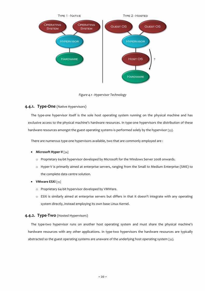
Broadly speaking, there are two categories of hypervisor technology in existence, type-one and type-two [33]. While
they provide comparable functionality to users of virtualisation, they differ considerably in their underlying operating
principle. Figure 4.1 shows the principle distinction between each hypervisor technology.
~ 20 ~
Figure 4.1 - Hypervisor Technology
4.4.1. Type-One (Native Hypervisors)
The type-one hypervisor itself is the sole host operating system running on the physical machine and has
exclusive access to the physical machine’s hardware resources. In type-one hypervisors the distribution of these
hardware resources amongst the guest operating systems is performed solely by the hypervisor [33].
There are numerous type-one hypervisors available, two that are commonly employed are :
Microsoft Hyper-V [34]
o Proprietary 64-bit hypervisor developed by Microsoft for the Windows Server 2008 onwards.
o Hyper-V is primarily aimed at enterprise servers, ranging from the Small to Medium Enterprise (SME) to
the complete data centre solution.
VMware ESXi [35]
o Proprietary 64-bit hypervisor developed by VMWare.
o ESXi is similarly aimed at enterprise servers but differs in that it doesn’t integrate with any operating
system directly, instead employing its own base Linux Kernel.
4.4.2. Type-Two (Hosted Hypervisors)
The type-two hypervisor runs on another host operating system and must share the physical machine’s
hardware resources with any other applications. In type-two hypervisors the hardware resources are typically
abstracted so the guest operating systems are unaware of the underlying host operating system [33].
~ 21 ~
Conversely, as alluded to in Figure 4.1 and discussed in Section 4.3 recent developments in hardware
virtualisation have allowed guest operating systems in type-two hypervisors to directly access the physical
machine’s hardware resources in much the same way as they would in type-one hypervisor. The distinction
between the two can thusly be frequently misleading and overly simplistic [36]. In addition, para-virtualisation has
also allowed type-two hypervisors to emulate the virtualisation characteristics in type-one hypervisors.
Similarly, there are numerous type-two hypervisors available, two that are commonly employed are :
Oracle VirtualBox [37]
o A 32 / 64-bit hypervisor developed by Oracle, freely licensed under the GNU General Public License.
o VirtualBox targets a wide range of platforms including servers, desktops and embedded systems.
VMware WorkStation & Player [38]
o Proprietary 32 / 64-bit hypervisor developed by VMWare.
o WorkStation & Player both use the same underlying core with WMware Player being freely available.
4.5. Operation of Hypervisors (Hyper-V Case Study)
Hyper-V is Microsoft’s own flagship virtualisation platform. It has been available to users through various editions of
the Windows Server operating system since 2008. Significantly, a wholly internal, bespoke version of Hyper-V serves as
the underlying operating system of Azure.
Hyper-V is designed using the micro-kernel architecture. This design places the proprietary device drivers in each
virtual machine and the virtualization stack is housed by a unique virtual machine whose primary role is to setup, deploy
and manage a Hyper-V solution. This allows for ease in isolating individual virtual machines while reducing the possible
attack surface. In contrast, VMware ESXi is designed using the monolithic-kernel architecture, meaning that the
proprietary device drivers and virtualization stack are placed within the hypervisor alone. This allows for ease in moving
individual virtual machines while consolidating the proprietary device drivers.
When the necessary virtual machine drivers and services are installed on the guest operating system, Hyper-V delivers
performance approaching that of a host operating system running on physical hardware. This is achieved through
Hyper-V virtual machine client code, also known as Hyper-V enlightened I/O enabling direct access to the Hyper-V virtual
machine bus, bypassing any device emulation. Both Windows Server 2008 R2 and Windows 7 onwards support Hyper-V
enlightened I/O through the installation of Hyper-V Integration Services. [39]. Hyper-V Integration Services are also
available for other client operating systems including several Linux distributions [40].
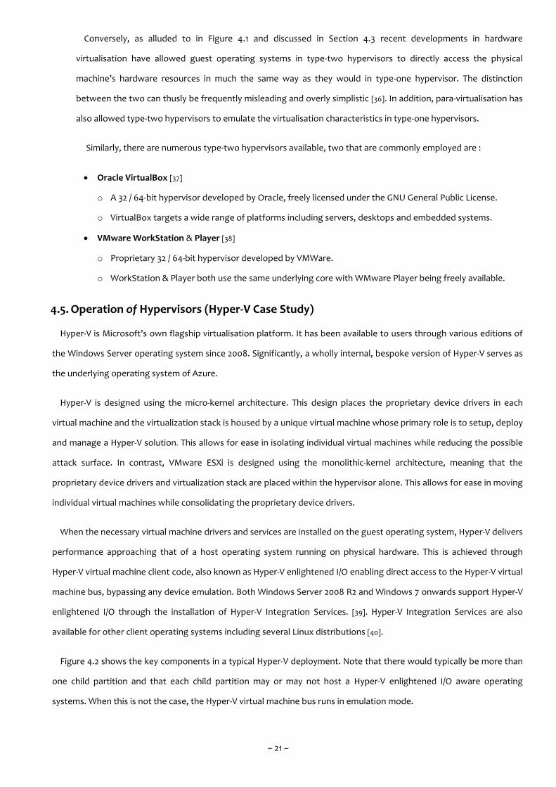
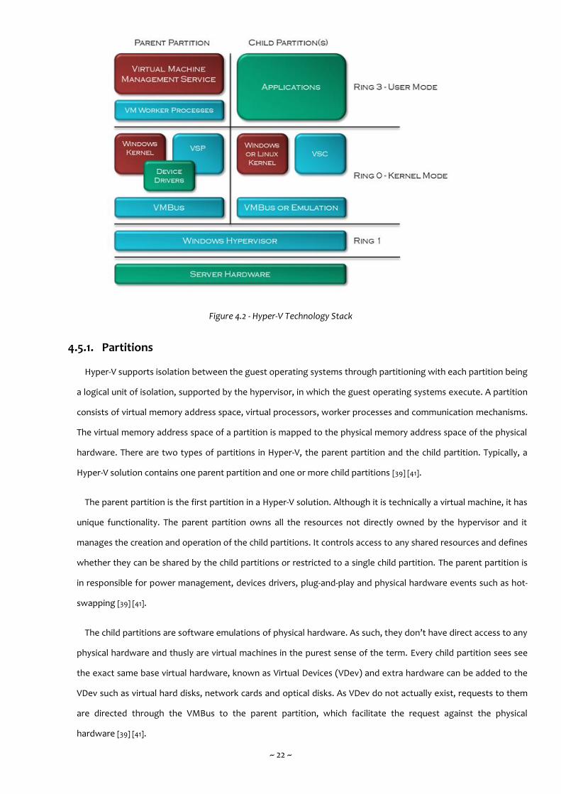
Figure 4.2 shows the key components in a typical Hyper-V deployment. Note that there would typically be more than
one child partition and that each child partition may or may not host a Hyper-V enlightened I/O aware operating
systems. When this is not the case, the Hyper-V virtual machine bus runs in emulation mode.
~ 22 ~
Figure 4.2 - Hyper-V Technology Stack
4.5.1. Partitions
Hyper-V supports isolation between the guest operating systems through partitioning with each partition being
a logical unit of isolation, supported by the hypervisor, in which the guest operating systems execute. A partition
consists of virtual memory address space, virtual processors, worker processes and communication mechanisms.
The virtual memory address space of a partition is mapped to the physical memory address space of the physical
hardware. There are two types of partitions in Hyper-V, the parent partition and the child partition. Typically, a
Hyper-V solution contains one parent partition and one or more child partitions [39] [41].
The parent partition is the first partition in a Hyper-V solution. Although it is technically a virtual machine, it has
unique functionality. The parent partition owns all the resources not directly owned by the hypervisor and it
manages the creation and operation of the child partitions. It controls access to any shared resources and defines
whether they can be shared by the child partitions or restricted to a single child partition. The parent partition is
in responsible for power management, devices drivers, plug-and-play and physical hardware events such as hot-
swapping [39] [41].
The child partitions are software emulations of physical hardware. As such, they don’t have direct access to any
physical hardware and thusly are virtual machines in the purest sense of the term. Every child partition sees see
the exact same base virtual hardware, known as Virtual Devices (VDev) and extra hardware can be added to the
VDev such as virtual hard disks, network cards and optical disks. As VDev do not actually exist, requests to them
are directed through the VMBus to the parent partition, which facilitate the request against the physical
hardware [39] [41].
~ 23 ~
4.5.2. VSP (Virtualization Service Providers) & VSC (Virtualization Service Clients)
The VSP are kernel-mode, software components that run on the parent partition and handle the I/O requests
that support the child partitions. The VSP provides this I/O interface via the VMBus to one or more VSC. VSP also
communicate directly with the physical hardware via the windows driver stack and proprietary device drivers to
facilitate system wide I/O requests using an Application Programming Interface (API) called HyperCall [39] [41].
The VSC are kernel-mode, synthetic device drivers that run on the child partitions. The VSC utilize the physical
hardware that has been provisioned by the corresponding VSP in the parent partition and communicate across
the VMBus to the VSP to invoke the child partitions I/O requests. Critically, the entire process is unseen to the
guest operating system [39] [41].
4.5.3. VMBus
The VMBus is a kernel-mode, high speed communication mechanism facilitating point-to-point communication
between child partitions and the parent partition as well as device enumeration. A single VSP can communicate
with multiple VSC and each VSP provides a dedicated channel for each child partition’s VSC [39] [41].
4.5.4. Virtual Machine Management Service
The Virtual Machine Management Service (VMMS) is a user mode, collection of software components that
manage virtual machines, primarily by creating and maintaining worker processes for child partitions. The VMMS
exists as a user-mode, executable service module under the windows service name Hyper-V Virtual Machine
Management [39] [41].
4.5.5. Virtual Machine Worker Process
The VMMS spawns a separate user-mode, Virtual Machine Worker Process (VMWP) for each virtual machine
that is operating or being configured. The VMWP provides management services from the parent partition to the
guest operating systems in the child partitions, including managing the virtual machines running state, managing
any associated VDev and managing Remote Desktop Protocol (RDP) sessions [39] [41].
4.6. Management of Hypervisors (Hyper-V Case Study)
Within the parent partition of Hyper-V, the VMMS exposes a set of Windows Management Instrumentation (WMI)
interfaces and their corresponding native Component Object Model (COM) Application Programming Interfaces (APIs)
for virtual machine management. WMI interfaces consist of a WMI service hosting WMI providers serving requests by
WMI clients and every characteristic concerning virtual machines can be monitored and controlled using the
appropriate WMI classes for Hyper-V [42]. In the most recent version, now called Windows Management Infrastructure,
the ability to communicate programmatically with WMI interfaces through the .NET 4 Framework has been fully
implemented and thusly, now supports comparable functionality to the native COM APIs [43].

~ 24 ~
Similarly, a constantly expanding set of Windows PowerShell cmdlets (cmdlets perform an action and typically return
a .NET 4 Framework object to the next operation in the pipeline) exist for virtual machine management, the significant
advantage being the highly scriptable nature of Windows PowerShell [44].
When deploying Hyper-V, the default high level management tools (designed atop WMI) consist of Hyper-V Manager,
which is a Microsoft Management Console (MMC) snap in and Virtual Machine Connection, which provides remote
connectivity to one or more virtual machines. However, Hyper-V Manager is considered a basic control panel, providing
only a minimal set of administrative operations such as starting / stopping virtual machines and configuring them when
they are not online.
Under ongoing development and provisioning many more administrative operations is System Centre Virtual Machine
Manager (designed atop Windows PowerShell). The Virtual Machine Manager (VMM) is Microsoft’s primary
management suite for hypervisors, enabling the robust configuration and management of physical and virtual servers,
networks and data storage resources either visually through a Graphical User Interface (GUI) dashboard or
programmatically through Windows PowerShell scripting. The VMM supports not only Hyper-V but other hypervisors
including VMware ESXi and may also integrate fully with Azure [45].
The VMM is composed of numerous software components that facilitate its management operations including
monitoring, data persistence, cataloguing and human interaction [45]. The key software components in a deployment of
VMM are as follows :
VMM Management Service.
o They primary operating component that processes commands and controls communications between the
VMM Database, VMM Library and the physical and virtual servers, networks and data storage resources.
VMM Database.
o Any configuration data is stored within a Microsoft SQL Server database. The data is primarily meta data
concerning the contents of the library catalogue including virtual machine templates, virtual data storage
metrics, operating profiles and task scheduling agents.
VMM Library.
o The actual library catalogue (e.g. the actual virtual machine templates, virtual data storage metrics, operating
profiles and task scheduling agents). A separate server that is sync with the VMM Database hosts the library
catalogue in various shared folders that contain the file system resources.
VMM Console.
o The primary human interaction component, a GUI allowing connections to one or more VMM Management
Services. The VMM Console allows for the central management of the physical and virtual servers, networks
and data storage resources, including virtual machine hosts and guests, services and the VMM Library.
~ 25 ~
VMM Command Shell.
o The secondary human interaction component allowing for direct programmatic access to the Windows
PowerShell cmdlets that underpin the core functionality of the VMM Management Services.
4.7. Summary
Contrasting the previous two chapters that focused solely on making the case for virtualisation, this chapter has
delved into virtualisation directly, discussing the various types of virtualisation that are available, cataloguing the
history of hypervisors and exploring the concepts that underpin the technology. Ultimately, the anticipated VMS sole
responsibility is the management of hypervisors and so this chapter concluded with a case study into one of the most
common hypervisors in industry today along with an investigation into the existing and emerging management
mechanisms. Critically, as much as the anticipated VMS is presently concerned, identifying suitable pathways to
communicate with hypervisors programmatically is this chapter’s key outcome.

~ 26 ~
Chapter Five ~ Programming Paradigms
5.1. Overview
This chapter commences with a discussion of programming language design, firstly by identifying some desirable
operating characteristics before exploring the concepts that underpin two key programming paradigms. While it is
both undesirable and unnecessary to describe every single operating characteristic / programming paradigm or the
myriad of interactions that may exist between them, we are ultimately concerned with two key, common place
paradigms (imperative and declarative) and some relatively recent interactions (object mapping and attribute oriented
programming) that frequently exist between them.
5.2. Programming Language Design
The ongoing study surrounding programming language design is by modern standards an ancient one. As the chapter
introduction stated, there are too many programming paradigms to realistically catalogue without a dedicated study
and there are yet innumerably more operating characteristics to any programming language’s specific nature and
composition. However, within the scope of the anticipated development to come, there are a number of desirable
operating characteristics that any candidate programming language should ideally support. These can be broadly
defined as follows :
5.2.1. Expressivity
When a programming language is perceived to be simple to write code in, that is readily understandable by
both humans and machines, then that programming language can be considered to be a more expressive
programming language than one which is more complex to write code in [46].
There are two key factors influencing this relative simplicity or complexity [46]. The first is intuitively legible
constructs (e.g. assembly language is less legible to humans than jQuery and while to machines, the reverse
might be true, compilers eliminate such a concern). The second is a minimum amount of boilerplate code (e.g. a
basic C# console application contains one or more package imports, a namespace, a class and an entry point
method with parameters while a basic F# console application contains nothing) [47] [48].
5.2.2. Abstraction
In software engineering, abstraction is a mechanism for managing the complexity of a computing problem by
supressing the many low level characteristics thereby reducing the computing problem to only a few high level
characteristics. This is typically achieved by encapsulating attributes and operations that do not need to be visible
to the developers (e.g. in the .NET 4 Framework, the StringBuilder class is an abstraction atop a character buffer
that allows developers to use the character buffer without concern for its low level operation).
~ 27 ~
Abstraction also forms one of the primary pillars of the object oriented paradigm and for good reason. It is not
necessary for the consumer of a given service to fully or even partially understand how that given service actually
works. A typical object oriented programming language (e.g. C# and Java) may use keywords (e.g. interface,
virtual, override and sealed) to define how an abstraction is to be utilized [47] [49].
5.2.3. Inheritance & Polymorphism
These are to two software engineering concepts that are logically separate but when activing together, also
form one of the primary pillars of the object oriented paradigm. Inheritance focusses on reusing existing data and
functionality from one base class (or super-class) in a wholly separate derived class (or sub-class). Typically the
two classes share at minimum, a moderate degree of commonality in terms of their constituent data and
functionality. Polymorphism recognises that while there is this commonality, there may also be a need for subtle
differences in the specific data and functionality. Polymorphism thusly allows for variations through a mechanism
knows as overriding (e.g. in the JavaSE Library the Writer class is a base class for writing to character streams and
there are numerous derived classes that inherit the data and functionality of the Writer class but which require a
unique twist, so the derived classes override the functionality that they initially inherited from the base class) [47]
[49].
5.2.4. Portability
When the same programming language can serve the same purpose (or even a differing purpose) on disparate
platforms then that programming language can be considered portable. In such a case, the developer’s
productivity may be increased while the development costs may be decreased simply by virtue of the familiarity
and commonality of the programming language respectively. Such a capability typically requires the
programming language to be platform agnostic, not concerned with the particulars of the platform. Frequently, a
virtual machine / runtime environment is employed between the programming language and the underlying
platform to translate the semantics of the programming language into the comparable semantics of underlying
platform [47] [48] [49].
5.2.5. Exception Handling
In software engineering it is commonly known that there are two categories of programmatic errors. The first
are compile-time errors that characterize themselves as a refusal of the parsing or pre-processing mechanism to
complete the compilation of the given code. Typically, compile-time errors arise from erroneous syntax and
usually manifest themselves as textual feedback from the parsing or pre-processing mechanism or as visual
feedback from a suitably configured Integrated Development Environment (IDE). The second are run-time errors
that characterize themselves as exceptions during execution. Typically, run-time errors arise from erroneous
semantics and usually manifest themselves as a fatal failure when not wrapped in appropriate try and catch
blocks underpinned by a native exception handling mechanism [47] [48] [49].
~ 28 ~
5.3. The Imperative Language
An imperative programming language allows developers to specify in a step-by-step fashion, how a problem should
be solved using a series of low level statements that change a program’s state. An imperative language thusly offers
fine grain control over the programming problem to be solved. A common example of an imperative language can be
found in C# and Java.
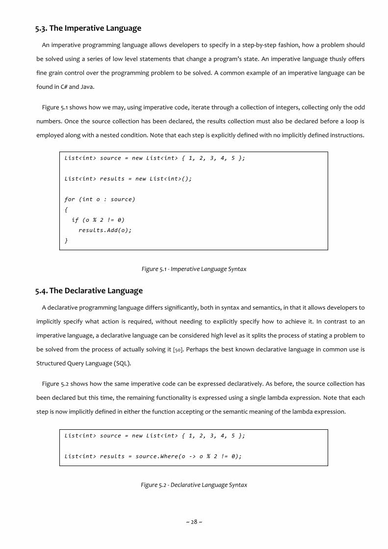
Figure 5.1 shows how we may, using imperative code, iterate through a collection of integers, collecting only the odd
numbers. Once the source collection has been declared, the results collection must also be declared before a loop is
employed along with a nested condition. Note that each step is explicitly defined with no implicitly defined instructions.
Figure 5.1 - Imperative Language Syntax
5.4. The Declarative Language
A declarative programming language differs significantly, both in syntax and semantics, in that it allows developers to
implicitly specify what action is required, without needing to explicitly specify how to achieve it. In contrast to an
imperative language, a declarative language can be considered high level as it splits the process of stating a problem to
be solved from the process of actually solving it [50]. Perhaps the best known declarative language in common use is
Structured Query Language (SQL).
Figure 5.2 shows how the same imperative code can be expressed declaratively. As before, the source collection has
been declared but this time, the remaining functionality is expressed using a single lambda expression. Note that each
step is now implicitly defined in either the function accepting or the semantic meaning of the lambda expression.
Figure 5.2 - Declarative Language Syntax
List<int> source = new List<int> { 1, 2, 3, 4, 5 };
List<int> results = new List<int>();
for (int o : source)
{
if (o % 2 != 0)
results.Add(o);
}
List<int> source = new List<int> { 1, 2, 3, 4, 5 };
List<int> results = source.Where(o -> o % 2 != 0);

~ 29 ~
Interestingly both Figure 5.1 and Figure 5.2 are written in the same, originally imperative language, with Figure 5.2
representing extensions that incorporate some new declarative constructs. The inverse may be seen in a language that
was originally purely declarative in nature. SQL is a common example having been subject to new imperative
constructs, such as conditions, loops and functions, being incorporated at a later stage.
5.4.1. Object Mapping
An object mapping declarative language allows designers and developers to specify considerable amounts of
syntactically complete, object oriented, imperative code without actually writing any imperative code. The key
advantages of this approach are quick design and development and ease of modification and maintenance.
A cogent example of such a language is eXtensible Application Markup Language (XAML) [51] released by
Microsoft in 2006 as part of the .NET 3 Framework. Originally, XAML was designed as a Graphical User Interface
(GUI) markup language for Windows Presentation Foundation (WPF) and subsequently SilverLight. As both these
technologies were slowly deprecated, XAML would somewhat fade into obscurity until it was revived by Xamarin
who began to use it once more as a GUI markup language supporting their multi-platform smart device
development framework [52]. Quite ironically, Microsoft would acquire Xamarin in early 2016.
As a language, XAML is developed from eXtensible Markup Language (XML) and allows designers and
developers to specify components of the .NET Common Language Runtime (CLR) in a nested hierarchy structure
[51]. When parsed, XAML markup is mapped to classes in the .NET CLR and the appropriate imperative code
(typically C#) is generated.
While XAML is extensible, it does have restrictions placed upon its tag set, as the declarative markup must be
mapped to the comparable imperative code (e.g. any .NET CLR namespaces are generally mapped to XAML
namespaces, classes are generally mapped as elements (or tags) and properties of those classes are generally
mapped as attributes). Thusly, to introduce additional namespaces, elements or attributes to XAML requires that
the underlying imperative code have been written previously [53].
Critically, XAML as a language supports each and every desirable operating characteristics as discussed in
Section 5.2, including expressivity, abstraction, inheritance, polymorphism, portability and exception handling.
Figure 5.3 shows two very simple class declarations written in C# that contain three and two properties (i.e.
class variables) respectively and default constructors. Note that object mapping with XAML doesn’t require non-
default constructors as objects are instantiated using the reflection mechanism in the .NET 4 Framework [53].

~ 30 ~
Figure 5.3 - Very Simple C# Objects
Figure 5.4 shows how objects of these classes can be instantiated and have their properties set with the usual
imperative syntax (using C#). Figure 5.5 shows how with an object mapping declarative language (using XAML),
the same objects can be specified declaratively with a more concise XML like syntax using a nested hierarchy
structure.
public class Author
{
public string Name { get; set; }
public string University { get; set; }
public IList<Works> Works { get; set; }
. .
public Author()
{
}
. .
}
public class Works
{
public string Title { get; set; }
public DateTime Release { get; set; }
. .
public Works()
{
}
. .
}

~ 31 ~
Figure 5.4 - Instantiating Objects Imperatively (using C#)
Figure 5.5 - Instantiating Objects Declaratively (using XAML)
Note that not only is the declarative language shown in Figure 5.5 less verbose (128 characters) in comparison
with the imperative language shown in Figure 5.4 (212 characters) but the declarative language also nests
elements in a much more readily understandable way thanks to a hierarchy structure. In contrast, the imperative
language must declare any nested objects before the containing object in which they are ultimately
encapsulated. Finally, specific knowledge of the .NET 4 Framework is required when instantiating a DateTime
object imperatively (e.g. using the Parse method), but not when instantiating declaratively.
5.4.2. Attribute Oriented Programming
The attribute oriented programming paradigm aims to support developers in extending source code semantics
through the addition of decorative comments called annotations. Annotations allow developers to express these
source code semantics implicitly, in a declarative way and by hiding the specifics of these semantics, attribute
oriented programming may increase programming abstraction and reduce programming complexity. Many a
programming language now provisions attribute oriented programming in support of programming initiatives
including web services, unit testing and object relational mapping [54] [55].
<Author ID="Author1" Name="GlynH" University="LJMU">
<Works ID="Works1" Title="jQuery Design" Release="05 Nov 2011" />
</Author>
Works Works1 = new Works();
Works1.Title = "jQuery Design";
Works1.Release = DateTime.Parse("05 Nov 2011");
Author Author1 = new Author();
Author1.Name = "GlynH";
Author1.University = "LJMU";
Author1.Works.Add(Works1);

~ 32 ~
In the .NET 4 Framework, attribute oriented programming is achieved by declaring a custom attribute class that
inherits directly or indirectly from the System . Attribute class. Figure 5.6 shows how (using C#) we may define a
custom attribute class called Author. Any constructors require what are known as positional parameters; in this
case there are two strings called name and university. In addition, any fields (i.e. class variables) are known as
named parameters and must be both publically visible and read-writable; in this case there is one double called
version. Any positional parameters must be given suitable arguments upon instantiation whilst named
parameters are allowed to default [56].
The use of the System . AttributeUsage class (itself an attribute class) and System . AttributeTargets enumeration
along with the non-conditional or operator signifies that the Author custom attribute class may be applied to any
future class or programmatic interface declaration. Note in Figure 5.6 that when being applied, the positional
parameters do not require fully qualified naming during value assignment [56].
Figure 5.6 - Declaring Custom Attribute Class
Declaring a custom attribute class and applying it to target class or interface declaration doesn’t modify the
contents of the target class or interface in any way. Note in Figure 5.6 that the SomeClass class is initially totally
empty, but the Author annotation may still be applied.
[AttributeUsage(AttributeTargets.Interface | AttributeTargets.Class)]
public sealed class Author : Attribute
{
private string name;
private string university;
public double version;
public Author(string name, string university)
{
this.name = name;
this.university = university;
version = 1.0;
}
public string GetName() { return name; }
public string GetUniversity() { return university; }
}
. .
[Author("GlynH", "LJMU", version = 1.1)]
class SomeClass
{
. .
}

~ 33 ~
By using reflection, the source code semantics can be retrieved from the target class or interface. In the .NET 4
Framework, the key method is called GetCustomAttributes, a static method of the System . Attribute class and
which returns an array of Attribute objects that are the runtime equivalents of the source code semantics. Figure
5.7 shows how using this method, we may then iterate over the returned array, determining which annotations
were applied (based on the object type of each array element) and extracting the source code semantics from
the annotations.
Figure 5.7 - Reflecting Custom Attribute Class
Note that in the interests of efficiency, the custom attribute class is not actually instantiated until a query is
made against it using the GetCustomAttributes method. This characteristic supports the fact that declaring and
applying a custom attribute class doesn’t modify the contents of the target in any way [56].
5.5. The Multi-Paradigm Language
With the discussion concerning two key programming paradigms (imperative and declarative) having shown some
compatible concepts, a question may be raised about the ability of a language or Application Programming Interface
(API) to support more than one paradigm at the same time. This phenomena is known under the umbrella term, multi-
paradigm programming. The concept is simple; allow a language or API to be written using any number of differing
programming concepts [57]. The aforementioned language F# is cogent example of a multi-paradigm programming
language; supporting functional, imperative, object, asynchronous, parallel, meta and agent programming [48].
Attribute[] attributes =
Attribute.GetCustomAttributes(typeof(SomeClass));
foreach (Attribute attribute in attributes)
{
if (attribute is Author)
{
Author author = (attribute as Author);
Console.WriteLine(author.GetName + " " + author.version);
}
}

~ 34 ~
5.6. Summary
This chapter has attempted to richly yet concisely describe two key, common place programming paradigms that
both have direct relevance to the anticipated development to come. With the core functionality being provided by an
imperative language and the concise simplicity being provided by a declarative language, an important interaction
between them known as object mapping has been discussed in some depth. This chapter also commenced by
reinforcing the discussions to come concerning these programming paradigms by identifying some desirable operating
characteristics that are applicable to any programming language design.
~ 35 ~
Chapter Six ~ Framework Requirements
6.1. Overview
The previous four chapters have established the necessity, requirements, operating principle and management
characteristics of virtualisation along with an investigation into the various nuances of the imperative and declarative
language. This chapter now uses this knowledge to define a concise collection of functional and non-functional
requirements that the anticipated VMS must satisfy.
6.2. Operating Requirements
An important stage of the VMS design and development was to identify the virtualisation management operations
that the system would need to support. Assuming a scenario where virtualisation is backing cloud computing solutions,
the operations are provisionally defined as follows :
1. Setup / Configuration.
o The VMS must generate an initial system schema for cloud computing solutions that specifies both the
components required, such as servers, applications, services & databases, and the allowable performance
quotients such as bandwidth, latency and memory.
2. Resource Allocation.
o The VMS must allocate resources at install time (as 1 above) and re-allocate resources at runtime based on the
system schema and any violation of the specified performance quotients. This capability is closely coupled to
scaling and swapping (as 3 & 4 below).
3. Scaling Up & Scaling Down / Peak Management.
o The VMS must stipulate the conditions under which applications and services have resources granted or
revoked. Such action is taken in response to triggers either by the application or service in question or its
surrounding operating environment.
4. Swapping In & Swapping Out.
o A more aggressive case of scaling. The VMS must determine when the operating environment is no longer able
to satisfy the demands of the application or service and scaling is insufficient to rectify the problem.
5. QoS (Quality of Service).
o The VMS must describe the required QoS conditions and the VMS must interact with recovery (as 6 below) or
reporting (as 7 below) should service provision not satisfy these QoS conditions.
6. Redundancy / Recovery.
o The VMS must specify the levels of redundancy that are required whether it be redundancy across virtual,
physical or geographically distributed machines. Recovery procedures (varying in severity) may be stipulated
that outline the stance the VMS should take when problems arise.
~ 36 ~
7. Reporting.
o The VMS must have the ability to extract or generate reports concerning all measurable aspects. Reports may
be designed for humans and automatic / autonomic systems or the VMS itself, the latter allowing real-time
data to be fed back into the system schema.
In addition to the operations as discussed in the previous paragraph and assuming a scenario where virtualisation is
backing big data solutions, some extra operations are provisionally defined as follows :
8. Scheduling.
o The VMS must allow for the predictable scheduling of tasks within the big data technology stack through
suitably defined and designed work flows.
9. Prioritising.
o Many work flows typically carry a priority (varying in urgency), be they statically or dynamically avowed. The
VMS must support the prioritisation of work flows as well as that of whole components such as servers,
applications, services and databases.
The operations of the VMS must be accessible to both humans and automatic / autonomic systems via either an
imperative or declarative syntax. Though for reasons of concise simplicity, discussed in Section 5.4 and again in Section
7.6, the declarative syntax is preferable.
6.3. Human Interaction & Automatic / Autonomic Support
Due to the inherent hierarchy structure, the adoption of a declarative syntax allows for both humans and automatic /
autonomic systems to quickly learn and interact with the VMS [50], but both will require a suitable interface with which
to interact with the VMS.
For humans, a control panel / dashboard will be required that is capable of encapsulating the operations of the VMS
and which provides humans with both scripting based Input/Output (I/O) as well as visual I/O through a suitable
Graphical User Interface (GUI). Given that the management of virtualisation is typically geographically distributed, the
control panel / dashboard will need to support operations remotely and securely, through local networks or the
internet.
For automatic / autonomic systems, a mechanism will be required that allows suitably encapsulated autonomic
algorithms to be plugged-in to the VMS. To achieve this, a plug-in manger will be required that exposes and in return
expects a pre-determined series of programming interfaces. The encapsulated autonomic algorithms need then only
observe and obey the requirements of these programming interfaces.
~ 37 ~
Future development will see the VMS employ its own automatic / autonomic capability that will manifest itself in the
methods / operations that are performed by the VMS in response to any changes that are detected in the system
schema. The inclusion of an autonomic capability within the VMS will result in a more effective VMS with less time
wasted, waiting for human interaction and decision making.
At this juncture, the distinction between automatic and autonomic capability is worth formally addressing. As much
as anticipated VMS is presently concerned, automatic refers to non-intelligent “knee jerk” responses to events whereas
autonomic refers to intelligent decision making processes that may or not be responses to those same events.
6.4. Summary
Suitably equipped with the key characteristics of both cloud computing and big data systems, combined with an
understanding of the capabilities of hypervisors and of the object mapping declarative language, the functional and
non-functional requirements could finally be defined. This chapter began by identifying the virtualisation management
operations that the anticipated VMS must support before concluding by identifying the required interactions with both
humans and automatic / autonomic systems.
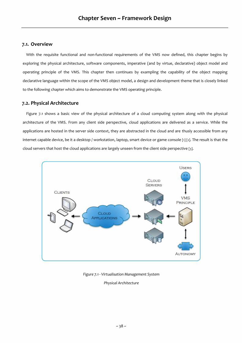
~ 38 ~
Chapter Seven ~ Framework Design
7.1. Overview
With the requisite functional and non-functional requirements of the VMS now defined, this chapter begins by
exploring the physical architecture, software components, imperative (and by virtue, declarative) object model and
operating principle of the VMS. This chapter then continues by exampling the capability of the object mapping
declarative language within the scope of the VMS object model, a design and development theme that is closely linked
to the following chapter which aims to demonstrate the VMS operating principle.
7.2. Physical Architecture
Figure 7.1 shows a basic view of the physical architecture of a cloud computing system along with the physical
architecture of the VMS. From any client side perspective, cloud applications are delivered as a service. While the
applications are hosted in the server side context, they are abstracted in the cloud and are thusly accessible from any
internet capable device, be it a desktop / workstation, laptop, smart device or game console [1] [2]. The result is that the
cloud servers that host the cloud applications are largely unseen from the client side perspective [3].
Figure 7.1 - Virtualisation Management System
Physical Architecture
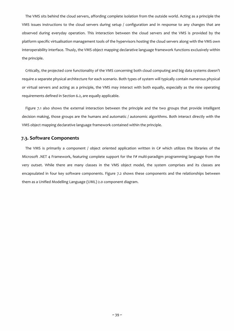
~ 39 ~
The VMS sits behind the cloud servers, affording complete isolation from the outside world. Acting as a principle the
VMS issues instructions to the cloud servers during setup / configuration and in response to any changes that are
observed during everyday operation. This interaction between the cloud servers and the VMS is provided by the
platform specific virtualisation management tools of the hypervisors hosting the cloud servers along with the VMS own
interoperability interface. Thusly, the VMS object mapping declarative language framework functions exclusively within
the principle.
Critically, the projected core functionality of the VMS concerning both cloud computing and big data systems doesn’t
require a separate physical architecture for each scenario. Both types of system will typically contain numerous physical
or virtual servers and acting as a principle, the VMS may interact with both equally, especially as the nine operating
requirements defined in Section 6.2, are equally applicable.
Figure 7.1 also shows the external interaction between the principle and the two groups that provide intelligent
decision making, those groups are the humans and automatic / autonomic algorithms. Both interact directly with the
VMS object mapping declarative language framework contained within the principle.
7.3. Software Components
The VMS is primarily a component / object oriented application written in C# which utilizes the libraries of the
Microsoft .NET 4 Framework, featuring complete support for the F# multi-paradigm programming language from the
very outset. While there are many classes in the VMS object model, the system comprises and its classes are
encapsulated in four key software components. Figure 7.2 shows these components and the relationships between
them as a Unified Modelling Language (UML) 2.0 component diagram.
~ 40 ~
Figure 7.2 - Virtualisation Management System UML
Component Diagram
At the core of the system is the Schema Monitor which is responsible for marshalling all modelling and scheduling
activity in the VMS. Initially and in simple terms it is an imperative assembly that receives declarative markup by way of
input from the XAML Handler, written by the human in the object mapping declarative language. It may also receive
declarative markup by way of input from the System Agent, which is responsible for scheduling activity. The declarative
markup is then converted to its imperative coding equivalent and commands are issued to the hypervisors via an
appropriate interoperability interface such as Windows Communication Foundation (WCF) web services / remoting and
Component Object Model (COM) interop.
The Schema Monitor is also responsible for interpreting data as it is actively or passively retrieved from the
hypervisors and modelling that data as revised declarative markup by way of output to the XAML Handler, thereby
facilitating any ongoing human interaction and decision making.

~ 41 ~
As discussed in Section 4.6, Virtual Machine Manager (VMM) is Microsoft’s primary management suite for hypervisors
and it contains two software components that provide long term data storage / archiving, the VMM Database and the
VMM Library. However, within the VMS, there is no immediate requirement for any comparable form of persistent data
beyond the semantic resources stored within the system schema as the hypervisors themselves manage the storage
and retrieval of the file system resources.
7.4. Object Model
The VMS contains two high level .NET Common Language Runtime (CLR) namespaces. The first is VMS . Core which
contains the operating classes that support the VMS as shown in Figure 7.2 (e.g. those belonging to Schema Monitor,
System Agent, XAML Handler and Plug-in Manager). The second is VMS . Entity which contains the classes that model
the objects within the VMS.
Figure 7.3 shows the most noteworthy objects in the namespace VMS . Entity. The object oriented design
methodology suits the VMS due to the inherent modularity of virtualisation components such as servers, applications,
services & databases. As with any object oriented solution, many objects within the VMS are not sealed and as such can
be extended to define new objects, assuming they are defined with appropriate polymorphic behaviours.
Figure 7.3 - Virtualisation Management System
Object Model Diagram
~ 42 ~
Broadly speaking, any VMS solution is firstly composed of a Cloud class object. In object oriented theory, the Cloud
class object is just a convenient placeholder for the root object in the inheritance hierarchy structure (comparable to
System . Object in the .NET 4 Framework). In practicality, Cloud class object represents a principle server whose purpose
is to perform no other task than to manage the working servers, be they physical or virtual in nature. Each Cloud class
object contains a collection of one or more IServer interface objects. The IServer interface objects may reference a
Physical or Virtual class object thusly allowing for polymorphic behaviour through a common set of methods. In much
the same fashion, each IServer interface object can contain one or more IContent interface objects. The IContent
interface objects may reference an Application or Service class object or an IStorage or ICommunicate interface object.
The same process is applied again for the IStorage and ICommunicate interface objects. During the development cycle, it
has not been necessary to abstract the Application or Service classes into their own interfaces or to specify any sub
classes, though this may change in any future development.
7.5. Operating Principle
In everyday operation, the VMS perpetually loops at any required time interval. Figure 7.4 shows how having
commenced with the employment of an initial system schema, the VMS proceeds to carry out a periodic analysis of the
system schema. When changes are required, an appropriate event mechanism is triggered and the changes are made to
the system schema. The revised system schema is then re-employed and the periodic analysis process starts again.

~ 43 ~
Figure 7.4 - Virtualisation Management System
Control Flow Diagram
The VMS . Entity objects are the only components of the VMS to which both humans and automatic / autonomic
algorithms have programmatic access. Each VMS . Entity object (with the exception of the Cloud object) is nested in a
containing object and each specifies its own initial configuration along with a set of Threshold attributes and Restriction
attributes.
The Threshold attributes are a series of allowable performance quotients for each noteworthy hardware, software
and networking resource. Critically, they are extensible so an exhaustive series at design time is not desirable. During
the current development cycle, these attributes are specified as a series of key / value pairs separated by semicolons
with the equal sign connecting each keyword and its value. The whole string is held in the appropriate object’s Worry
property and is parsed by the constructors (if applicable) and by the setter of the Worry property. An example Worry
property might be specified as follows :
{CPU=10; Memory=1024; Storage=32; Latency=50; BandWidth=500;}

~ 44 ~
The VMS would interpret this example Worry property as follows :
Processing must not drop below 10%.
Memory must not drop below 1024MB.
Data storage must not drop below 32MB..
Maximum network latency must not rise above 50ms.
Minimum network bandwidth must not drop below 500kb.
During a periodic analysis of the system schema, each Threshold attribute is extracted to determine if the associated
allowable performance quotients have been violated. Should this be the case, an appropriate Event is triggered to
inform the VMS that changes to the system schema are required and any Threshold attributes are extracted and
encapsulated in event arguments.
Alongside the Threshold attributes are the Restriction attributes which are a series of requisite requirements for each
noteworthy hardware, software and networking resource. The whole string is held in the appropriate object’s Want
property and is similarly parsed by the constructors (if applicable) and by the setter of the Want property. An example
Want property might be specified as follows :
{CPU=20; Memory=2048; OperatingSystem=Windows; DatabaseSystem=SQLS;}
The VMS would interpret this example Want property as follows :
Assigned 20% of processing.
Allocated 2048MB of memory.
The operating system must be Windows (or compatible).
The database system must be SQL Server (or compatible).
When an appropriate Event is triggered, any Restriction attributes are extracted and encapsulated in event arguments
that specify the requisite requirements that an Action object may work with as it attempts to make changes to the
system schema. Should the changes not violate the requisite requirements, then the Restriction attributes are ignored.
However, when the changes do violate the requisite requirements, the Action object must attempt to derive an
alternative strategy to address the cause of the Event being triggering.
The final step in the periodic analysis process is the Action performed in response to the triggering of an Event. Each
Action takes the form of an event handling method / operation. The VMS uses the data regarding the violation (from
the Event object), the allowable performance quotients (from the Threshold attributes) and the requisite requirements
(from the Restriction attributes) to make changes to the VMS . Entity objects before re-employing the revised system
schema.
~ 45 ~
7.5.1. Scheduling with System Agent
The System Agent, as shown in Figure 7.2 and discussed in Section 7.3 is responsible for scheduling activity. This
is provisioned by way of retrieving / employing the saved system schema in their native declarative markup. Each
saved system schema is associated with a given timing and the System Agent maintains a catalogue of these
pairings, triggering them when appropriate and retrieving / employing the saved system schema to the Schema
Monitor, in keeping with the VMS operating principle. The differing types of timings are provisionally defined as
follows :
Once Only.
o Suitable for single, foreknown events that may be scripted in advanced and which do not require human
interaction and decision making at the timing of their triggering. Such events might include any
scheduled component maintenance.
Recurring.
o Suitable for recurring, foreknown events that may be scripted against any required time interval, from
hours, though days and weeks to months. Such events might include the Extract Transform & Load (ETL)
process or any anticipated surge in one more components such as eCommerce systems during a Black-
Friday style shopping spree.
Triggered.
o A monitoring mechanism that allows for events internal or external to the VMS to be caught. These
events do not necessarily relate directly to the Threshold attributes defined within the saved system
schema but the action is much the same, with some change being made to the VMS . Entity objects
before re-employing the revised system schema.
In each instance, the pairings specify not only the given timing but also the time-to-live, during which time the
Schema Monitor may not revoke or re-organise any aspect of the saved system schema that the System Agent
has retrieved / employed.
7.6. Object Mapping Declarative Language
An object mapping declarative language allows designers and developers to specify considerable amounts of
syntactically complete, object oriented, imperative code without actually writing any imperative code [53]. The VMS is
able to fully demonstrate this advantage with even the most basic scenario.
~ 46 ~
As discussed in Section 7.4, the VMS defines a class called Physical (implementing interface IServer) which represents
a physical server. Class Physical has properties (amongst others) for the type of operating system, the memory capacity
and the data storage capacity. It also has a property which contains a collection of the currently hosted applications,
services, data storage and communication components. Similarly, a class called Database (implementing interface
IContent) represents a specific database instance within a Relational Database Management System (RDBMS). Class
Database has properties (amongst others) for the type of database system and the data storage capacity.
Figure 7.5 shows how such objects might exist, stubbed out in the underlying imperative language. Note that the
constructors are all currently non-default constructors. As an implementation issue, it is likely that multiple overloaded
constructors will be defined so as to allow objects to be either fully instantiated in one go or through property setting
at a later stage. However, as discussed in Section 5.4, object mapping with XAML doesn’t require non-default
constructors as objects are instantiated using the reflection mechanism in the .NET 4 Framework [53].
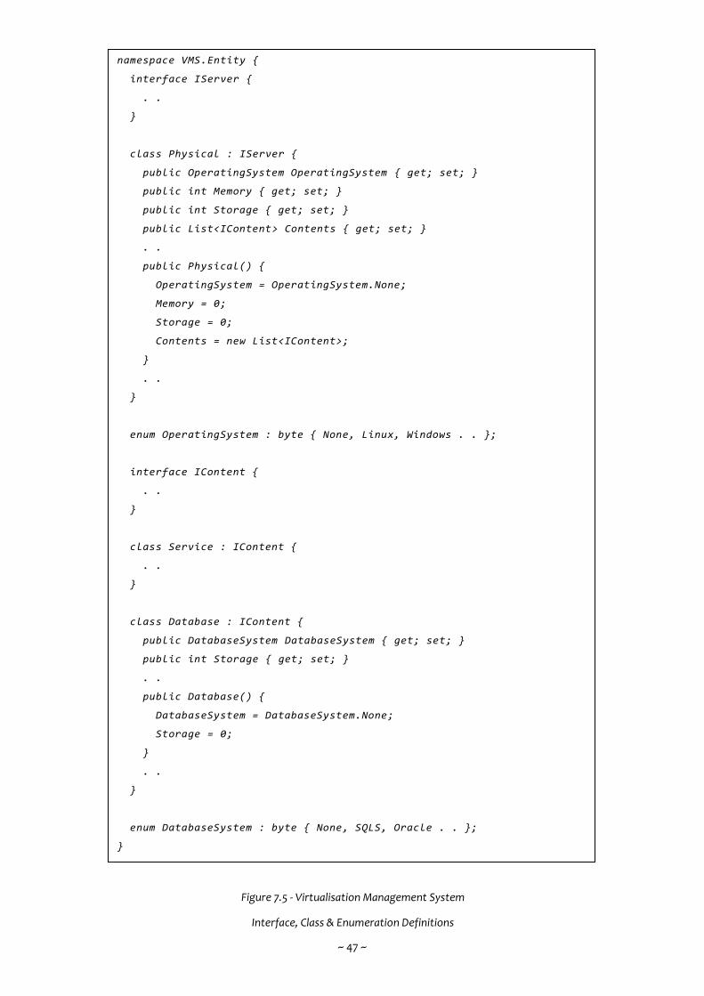
~ 47 ~
Figure 7.5 - Virtualisation Management System
Interface, Class & Enumeration Definitions
namespace VMS.Entity {
interface IServer {
. .
}
class Physical : IServer {
public OperatingSystem OperatingSystem { get; set; }
public int Memory { get; set; }
public int Storage { get; set; }
public List<IContent> Contents { get; set; }
. .
public Physical() {
OperatingSystem = OperatingSystem.None;
Memory = 0;
Storage = 0;
Contents = new List<IContent>;
}
. .
}
enum OperatingSystem : byte { None, Linux, Windows . . };
interface IContent {
. .
}
class Service : IContent {
. .
}
class Database : IContent {
public DatabaseSystem DatabaseSystem { get; set; }
public int Storage { get; set; }
. .
public Database() {
DatabaseSystem = DatabaseSystem.None;
Storage = 0;
}
. .
}
enum DatabaseSystem : byte { None, SQLS, Oracle . . };
}
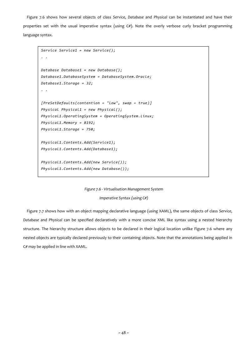
~ 48 ~
Figure 7.6 shows how several objects of class Service, Database and Physical can be instantiated and have their
properties set with the usual imperative syntax (using C#). Note the overly verbose curly bracket programming
language syntax.
Figure 7.6 - Virtualisation Management System
Imperative Syntax (using C#)
Figure 7.7 shows how with an object mapping declarative language (using XAML), the same objects of class Service,
Database and Physical can be specified declaratively with a more concise XML like syntax using a nested hierarchy
structure. The hierarchy structure allows objects to be declared in their logical location unlike Figure 7.6 where any
nested objects are typically declared previously to their containing objects. Note that the annotations being applied in
C# may be applied in line with XAML.
Service Service1 = new Service();
. .
Database Database1 = new Database();
Database1.DatabaseSystem = DatabaseSystem.Oracle;
Database1.Storage = 32;
. .
[PreSetDefaults(contention = "low", swap = true)]
Physical Physical1 = new Physical();
Physical1.OperatingSystem = OperatingSystem.Linux;
Physical1.Memory = 8192;
Physical1.Storage = 750;
Physical1.Contents.Add(Service1);
Physical1.Contents.Add(Database1);
Physical1.Contents.Add(new Service());
Physical1.Contents.Add(new Database());
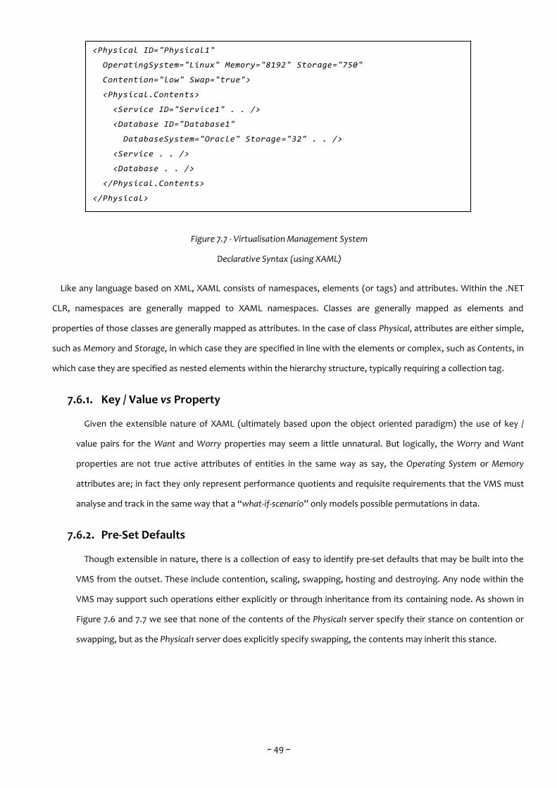
~ 49 ~
Figure 7.7 - Virtualisation Management System
Declarative Syntax (using XAML)
Like any language based on XML, XAML consists of namespaces, elements (or tags) and attributes. Within the .NET
CLR, namespaces are generally mapped to XAML namespaces. Classes are generally mapped as elements and
properties of those classes are generally mapped as attributes. In the case of class Physical, attributes are either simple,
such as Memory and Storage, in which case they are specified in line with the elements or complex, such as Contents, in
which case they are specified as nested elements within the hierarchy structure, typically requiring a collection tag.
7.6.1. Key / Value vs Property
Given the extensible nature of XAML (ultimately based upon the object oriented paradigm) the use of key /
value pairs for the Want and Worry properties may seem a little unnatural. But logically, the Worry and Want
properties are not true active attributes of entities in the same way as say, the Operating System or Memory
attributes are; in fact they only represent performance quotients and requisite requirements that the VMS must
analyse and track in the same way that a “what-if-scenario” only models possible permutations in data.
7.6.2. Pre-Set Defaults
Though extensible in nature, there is a collection of easy to identify pre-set defaults that may be built into the
VMS from the outset. These include contention, scaling, swapping, hosting and destroying. Any node within the
VMS may support such operations either explicitly or through inheritance from its containing node. As shown in
Figure 7.6 and 7.7 we see that none of the contents of the Physical1 server specify their stance on contention or
swapping, but as the Physical1 server does explicitly specify swapping, the contents may inherit this stance.
<Physical ID="Physical1"
OperatingSystem="Linux" Memory="8192" Storage="750"
Contention="low" Swap="true">
<Physical.Contents>
<Service ID="Service1" . . />
<Database ID="Database1"
DatabaseSystem="Oracle" Storage="32" . . />
<Service . . />
<Database . . />
</Physical.Contents>
</Physical>
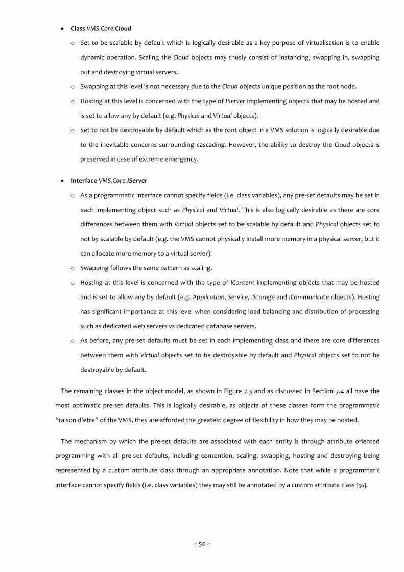
~ 50 ~
Class VMS.Core.Cloud
o Set to be scalable by default which is logically desirable as a key purpose of virtualisation is to enable
dynamic operation. Scaling the Cloud objects may thusly consist of instancing, swapping in, swapping
out and destroying virtual servers.
o Swapping at this level is not necessary due to the Cloud objects unique position as the root node.
o Hosting at this level is concerned with the type of IServer implementing objects that may be hosted and
is set to allow any by default (e.g. Physical and Virtual objects).
o Set to not be destroyable by default which as the root object in a VMS solution is logically desirable due
to the inevitable concerns surrounding cascading. However, the ability to destroy the Cloud objects is
preserved in case of extreme emergency.
Interface VMS.Core.IServer
o As a programmatic interface cannot specify fields (i.e. class variables), any pre-set defaults may be set in
each implementing object such as Physical and Virtual. This is also logically desirable as there are core
differences between them with Virtual objects set to be scalable by default and Physical objects set to
not by scalable by default (e.g. the VMS cannot physically install more memory in a physical server, but it
can allocate more memory to a virtual server).
o Swapping follows the same pattern as scaling.
o Hosting at this level is concerned with the type of IContent implementing objects that may be hosted
and is set to allow any by default (e.g. Application, Service, IStorage and ICommunicate objects). Hosting
has significant importance at this level when considering load balancing and distribution of processing
such as dedicated web servers vs dedicated database servers.
o As before, any pre-set defaults must be set in each implementing class and there are core differences
between them with Virtual objects set to be destroyable by default and Physical objects set to not be
destroyable by default.
The remaining classes in the object model, as shown in Figure 7.3 and as discussed in Section 7.4 all have the
most optimistic pre-set defaults. This is logically desirable, as objects of these classes form the programmatic
“raison d'etre” of the VMS, they are afforded the greatest degree of flexibility in how they may be hosted.
The mechanism by which the pre-set defaults are associated with each entity is through attribute oriented
programming with all pre-set defaults, including contention, scaling, swapping, hosting and destroying being
represented by a custom attribute class through an appropriate annotation. Note that while a programmatic
interface cannot specify fields (i.e. class variables) they may still be annotated by a custom attribute class [56].

~ 51 ~
7.7. Summary
This chapter’s priority has been to delve deeply rather than trawl widely, thusly the physical architecture, software
components and object model (which theoretically is heavily extensible) have all been described without the need for
an exhaustive cataloguing of each. That being said, this chapter has described in depth, the operating principle along
with a suitable example of the object mapping declarative language in situ along with the various supporting
mechanisms that allow the VMS to provide its core functionality. The following chapter extends on this by presenting
specific problems and hopefully the solutions that are typical of the VMS operating domain.
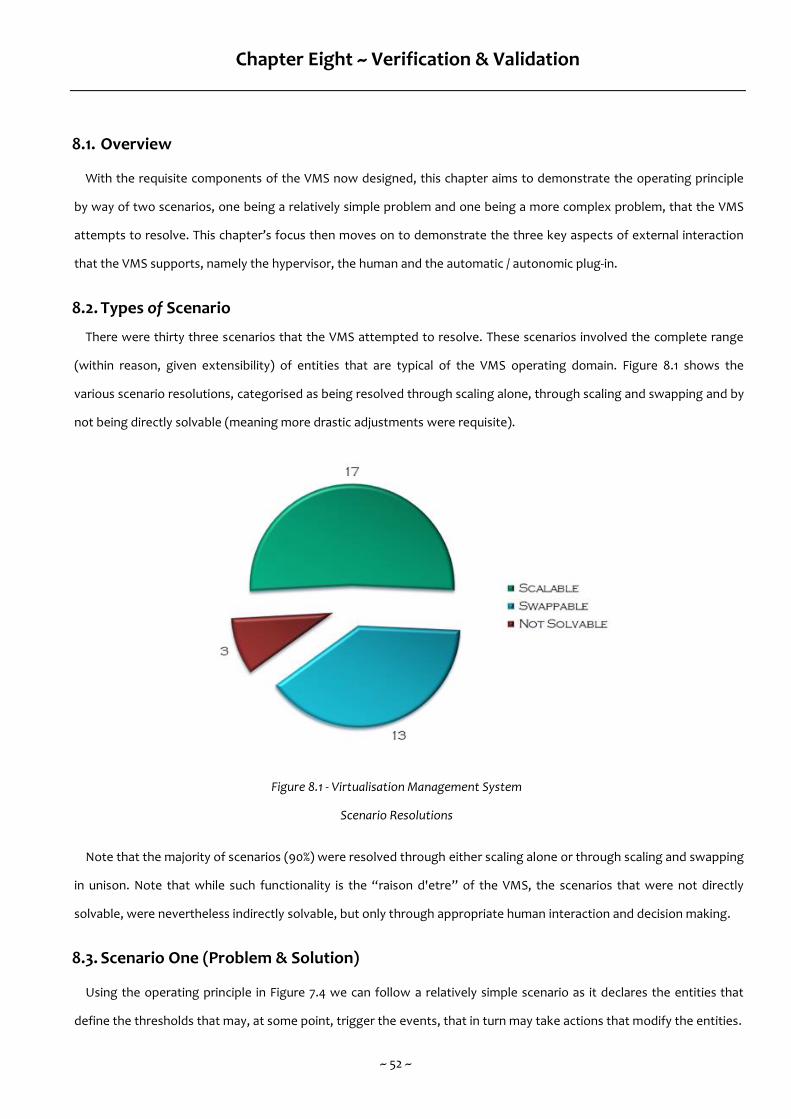
~ 52 ~
Chapter Eight ~ Verification & Validation
8.1. Overview
With the requisite components of the VMS now designed, this chapter aims to demonstrate the operating principle
by way of two scenarios, one being a relatively simple problem and one being a more complex problem, that the VMS
attempts to resolve. This chapter’s focus then moves on to demonstrate the three key aspects of external interaction
that the VMS supports, namely the hypervisor, the human and the automatic / autonomic plug-in.
8.2. Types of Scenario
There were thirty three scenarios that the VMS attempted to resolve. These scenarios involved the complete range
(within reason, given extensibility) of entities that are typical of the VMS operating domain. Figure 8.1 shows the
various scenario resolutions, categorised as being resolved through scaling alone, through scaling and swapping and by
not being directly solvable (meaning more drastic adjustments were requisite).
Figure 8.1 - Virtualisation Management System
Scenario Resolutions
Note that the majority of scenarios (90%) were resolved through either scaling alone or through scaling and swapping
in unison. Note that while such functionality is the “raison d'etre” of the VMS, the scenarios that were not directly
solvable, were nevertheless indirectly solvable, but only through appropriate human interaction and decision making.
8.3. Scenario One (Problem & Solution)
Using the operating principle in Figure 7.4 we can follow a relatively simple scenario as it declares the entities that
define the thresholds that may, at some point, trigger the events, that in turn may take actions that modify the entities.
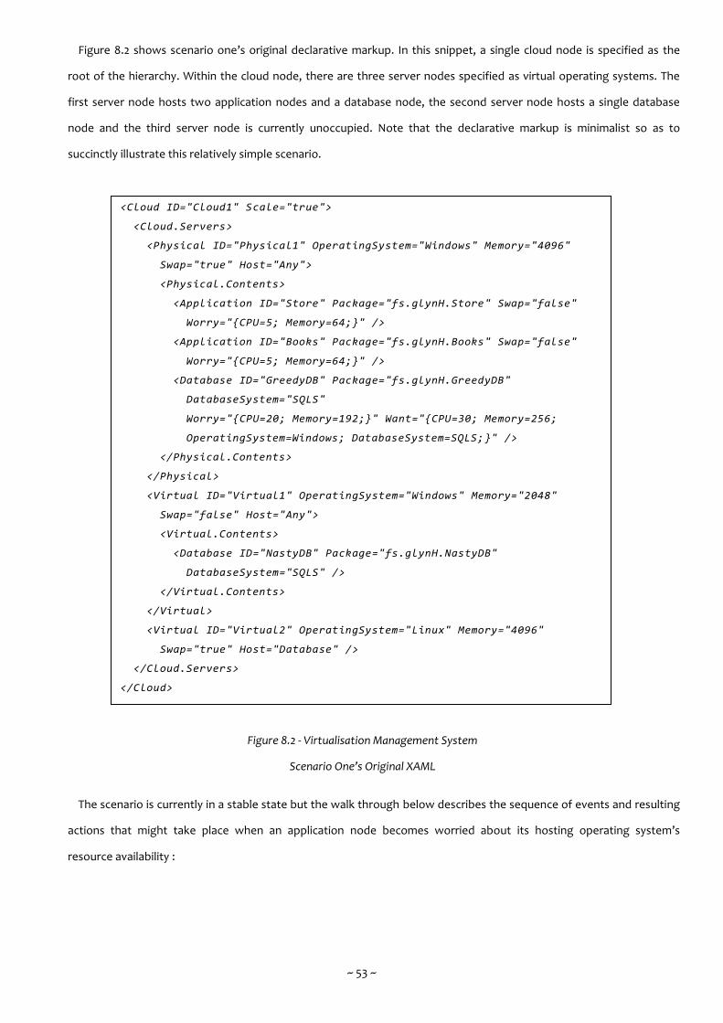
~ 53 ~
Figure 8.2 shows scenario one’s original declarative markup. In this snippet, a single cloud node is specified as the
root of the hierarchy. Within the cloud node, there are three server nodes specified as virtual operating systems. The
first server node hosts two application nodes and a database node, the second server node hosts a single database
node and the third server node is currently unoccupied. Note that the declarative markup is minimalist so as to
succinctly illustrate this relatively simple scenario.
Figure 8.2 - Virtualisation Management System
Scenario One’s Original XAML
The scenario is currently in a stable state but the walk through below describes the sequence of events and resulting
actions that might take place when an application node becomes worried about its hosting operating system’s
resource availability :
<Cloud ID="Cloud1" Scale="true">
<Cloud.Servers>
<Physical ID="Physical1" OperatingSystem="Windows" Memory="4096"
Swap="true" Host="Any">
<Physical.Contents>
<Application ID="Store" Package="fs.glynH.Store" Swap="false"
Worry="{CPU=5; Memory=64;}" />
<Application ID="Books" Package="fs.glynH.Books" Swap="false"
Worry="{CPU=5; Memory=64;}" />
<Database ID="GreedyDB" Package="fs.glynH.GreedyDB"
DatabaseSystem="SQLS"
Worry="{CPU=20; Memory=192;}" Want="{CPU=30; Memory=256;
OperatingSystem=Windows; DatabaseSystem=SQLS;}" />
</Physical.Contents>
</Physical>
<Virtual ID="Virtual1" OperatingSystem="Windows" Memory="2048"
Swap="false" Host="Any">
<Virtual.Contents>
<Database ID="NastyDB" Package="fs.glynH.NastyDB"
DatabaseSystem="SQLS" />
</Virtual.Contents>
</Virtual>
<Virtual ID="Virtual2" OperatingSystem="Linux" Memory="4096"
Swap="true" Host="Database" />
</Cloud.Servers>
</Cloud>
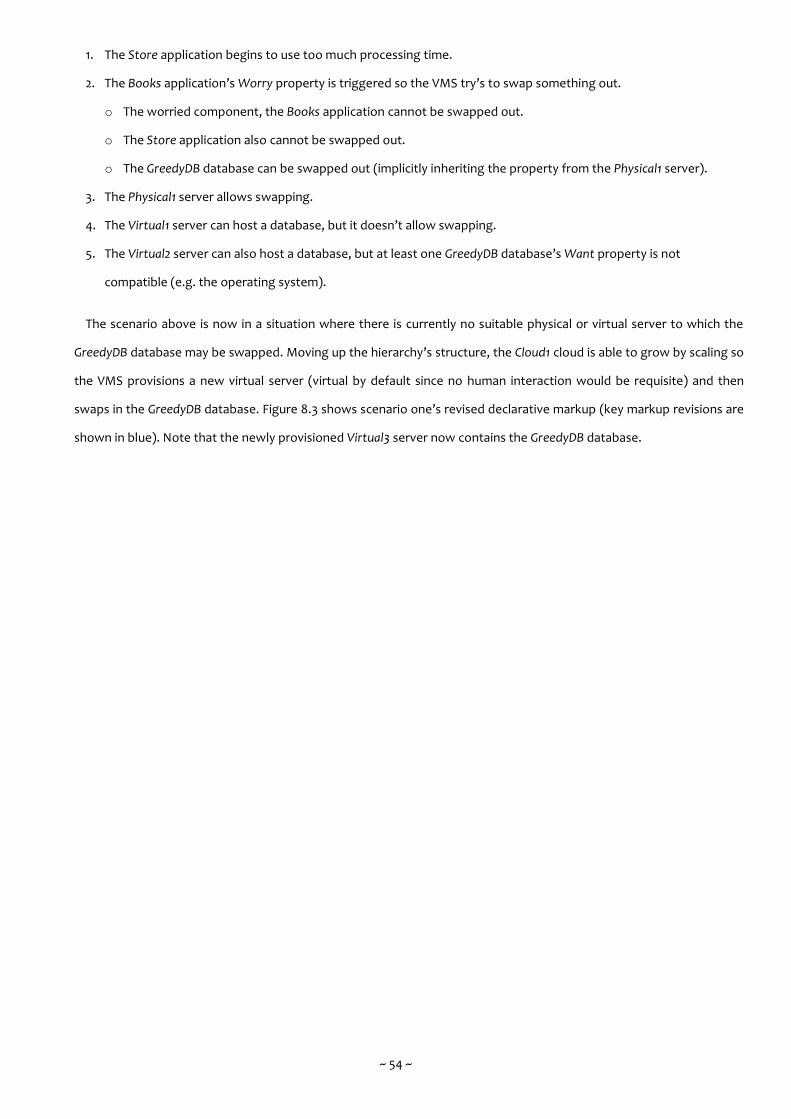
~ 54 ~
1. The Store application begins to use too much processing time.
2. The Books application’s Worry property is triggered so the VMS try’s to swap something out.
o The worried component, the Books application cannot be swapped out.
o The Store application also cannot be swapped out.
o The GreedyDB database can be swapped out (implicitly inheriting the property from the Physical1 server).
3. The Physical1 server allows swapping.
4. The Virtual1 server can host a database, but it doesn’t allow swapping.
5. The Virtual2 server can also host a database, but at least one GreedyDB database’s Want property is not
compatible (e.g. the operating system).
The scenario above is now in a situation where there is currently no suitable physical or virtual server to which the
GreedyDB database may be swapped. Moving up the hierarchy’s structure, the Cloud1 cloud is able to grow by scaling so
the VMS provisions a new virtual server (virtual by default since no human interaction would be requisite) and then
swaps in the GreedyDB database. Figure 8.3 shows scenario one’s revised declarative markup (key markup revisions are
shown in blue). Note that the newly provisioned Virtual3 server now contains the GreedyDB database.
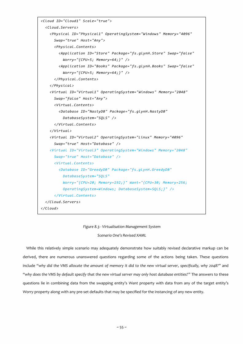
~ 55 ~
Figure 8.3 - Virtualisation Management System
Scenario One’s Revised XAML
While this relatively simple scenario may adequately demonstrate how suitably revised declarative markup can be
derived, there are numerous unanswered questions regarding some of the actions being taken. These questions
include “why did the VMS allocate the amount of memory it did to the new virtual server, specifically, why 2048?” and
“why does the VMS by default specify that the new virtual server may only host database entities?” The answers to these
questions lie in combining data from the swapping entity’s Want property with data from any of the target entity’s
Worry property along with any pre-set defaults that may be specified for the instancing of any new entity.
<Cloud ID="Cloud1" Scale="true">
<Cloud.Servers>
<Physical ID="Physical1" OperatingSystem="Windows" Memory="4096"
Swap="true" Host="Any">
<Physical.Contents>
<Application ID="Store" Package="fs.glynH.Store" Swap="false"
Worry="{CPU=5; Memory=64;}" />
<Application ID="Books" Package="fs.glynH.Books" Swap="false"
Worry="{CPU=5; Memory=64;}" />
</Physical.Contents>
</Physical>
<Virtual ID="Virtual1" OperatingSystem="Windows" Memory="2048"
Swap="false" Host="Any">
<Virtual.Contents>
<Database ID="NastyDB" Package="fs.glynH.NastyDB"
DatabaseSystem="SQLS" />
</Virtual.Contents>
</Virtual>
<Virtual ID="Virtual2" OperatingSystem="Linux" Memory="4096"
Swap="true" Host="Database" />
<Virtual ID="Virtual3" OperatingSystem="Windows" Memory="2048"
Swap="true" Host="Database" />
<Virtual.Contents>
<Database ID="GreedyDB" Package="fs.glynH.GreedyDB"
DatabaseSystem="SQLS"
Worry="{CPU=20; Memory=192;}" Want="{CPU=30; Memory=256;
OperatingSystem=Windows; DatabaseSystem=SQLS;}" />
</Virtual.Contents>
</Cloud.Servers>
</Cloud>
~ 56 ~
8.4. Scenario Two (Problem & Solution)
Using the operating principle in Figure 7.4 along with the differing types of timings of the System Agent we can
follow a more complex scenario as it declares the entities that will be undergoing management at the behest of the
System Agent.
Figure 8.4 shows scenario two’s original declarative markup. In this snippet, a single cloud node is specified as the
root of the hierarchy. Within the cloud node, there are three server nodes specified with two being physical operating
systems and one being a virtual operating system. There are differing contentions across the three server nodes and
the two database nodes that are currently hosted by the first server node. As before, note that the declarative markup
is minimalist so as to succinctly illustrate this more complex scenario.

~ 57 ~
Figure 8.4 - Virtualisation Management System
Scenario Two’s Original XAML
Figure 8.5 shows scenario two’s declarative markup as nested within the System Agent. In this snippet, there are two
agent nodes specified. The first agent node has attributes set including timing, interval and start date (not setting an
end date attribute implies the agent node is triggered according to schedule, indefinitely). The second agent node has
attributes set including interval, listen and status (setting the interval to triggered requires setting both the listen and
the status attributes). Both agent nodes also have the persist attribute set to false, indicating to the System Agent that
the nested declarative markup in each agent node should be removed in an attempt to restore scenario two’s original
declarative markup.
<Cloud ID="Cloud1" Scale="true">
<Cloud.Servers>
<Physical ID="Physical1" OperatingSystem="Windows" Memory="4096"
Contention="high" Swap="true" Host="Database">
<Physical.Contents>
<Database ID="MissionCrticalDB"
Package="fs.glynH.MissonCriticalDB"
DatabaseSystem="SQLS" Contention="high"
Worry="{CPU=30; Memory=256;}" Want="{CPU=40; Memory=320;
OperatingSystem=Windows; DatabaseSystem=SQLS;}" />
<Database ID="NonMissionCriticalDB"
Package="fs.glynH.NonMissionCriticalDB"
DatabaseSystem="SQLS" Contention="low"
Worry="{CPU=30; Memory=256;}" Want="{CPU=40; Memory=320;
OperatingSystem=Windows; DatabaseSystem=SQLS;}" />
</Physical.Contents>
</Physical>
<Physical ID="Physical2" OperatingSystem="Windows" Memory="4096"
Contention="low" Swap="true" Host="Any" />
<Physical.Contents>
<Application ID="Store" Package="fs.glynH.Store" Swap="false"
Worry="{CPU=5; Memory=64;}" />
<Application ID="Books" Package="fs.glynH.Books" Swap="false"
Worry="{CPU=5; Memory=64;}" />
</Physical.Contents>
<Virtual ID="Virtual1" OperatingSystem="Linux" Memory="2048"
Contention="low" Swap="false" Host="Any" />
</Cloud.Servers>
</Cloud>
~ 58 ~
Figure 8.5 - Virtualisation Management System
Scenario Two’s System Agent XAML
As before, the scenario is currently in a stable state but the walk through below describes the sequence of events and
resulting actions that might take place when the System Agent is triggered and the nested declarative markup in each
agent node is submitted for processing :
1. The Monthly-ETL agent is triggered (by date & time), beginning a search for a suitable hosting operating system.
2. Following the search, only one hosting operating system, the Physical1 server, is currently matching every
Monthly-ETL application’s Want property (e.g. the contention, operating system and database system).
3. The attempt is made to host the Monthly-ETL application within the Physical1 server.
o This results in a clash (specifically, processing time) between the Monthly-ETL application, the MissonCriticalDB
database and the NonMissionCriticalDB database.
o Amongst the three only the NonMissionCriticalDB database doesn’t require high contention and so can be
swapped out (implicitly inheriting the property from the Physical1 server).
4. The Physical1 server allows swapping.
5. The Physical2 server can host a database, it also allows swapping and every NonMissionCriticalDB database’s Want
property is compatible (e.g. the contention, operating system, database system, processing time and memory).
6. The Physical3 server can also host a database, but it doesn’t allow swapping and at least one NonMissionCriticalDB
database’s Want property is not compatible (e.g. the operating system).
<Agent ID="Monthly-ETL" Timing="Recurring"
Interval="Monthly" Start="01.01.2017 20:00:00"
Persist="false">
<Application ID="Monthly-ETL" Package="fs.glynH.SQLServerETL"
Contention="high" Swap="false" Scale="true"
Worry="{CPU=50; Memory=256;}" Want="{CPU=60; Memory=320;
OperatingSystem=Windows; DatabaseSystem=SQLS;}" />
</Agent>
<Agent ID="DataWH-CleanUp" Timing="Triggered"
Listen="Monthly-ETL" Event="Success"
Persist="false">
<Application ID="DataWH-CleanUp" Package="fs.glynH.SQLServerCleanUp"
Contention="low" Swap="true" Scale="true"
Want="{OperatingSystem=Windows; DatabaseSystem=SQLS;}" />
</Agent>
~ 59 ~
The scenario above is now in a situation where there is currently only a single suitable physical server to which the
NonMissionCriticalDB database may be swapped. Thusly, the VMS swaps in the NonMissionCriticalDB database to the
Physical2 server. Figure 8.6 shows scenario two’s revised declarative markup (key markup revisions are shown in blue).
Note that the Physical2 server now contains the NonMissionCriticalDB database and that there are no subsequent
clashes with the already existing Store application and Books application.
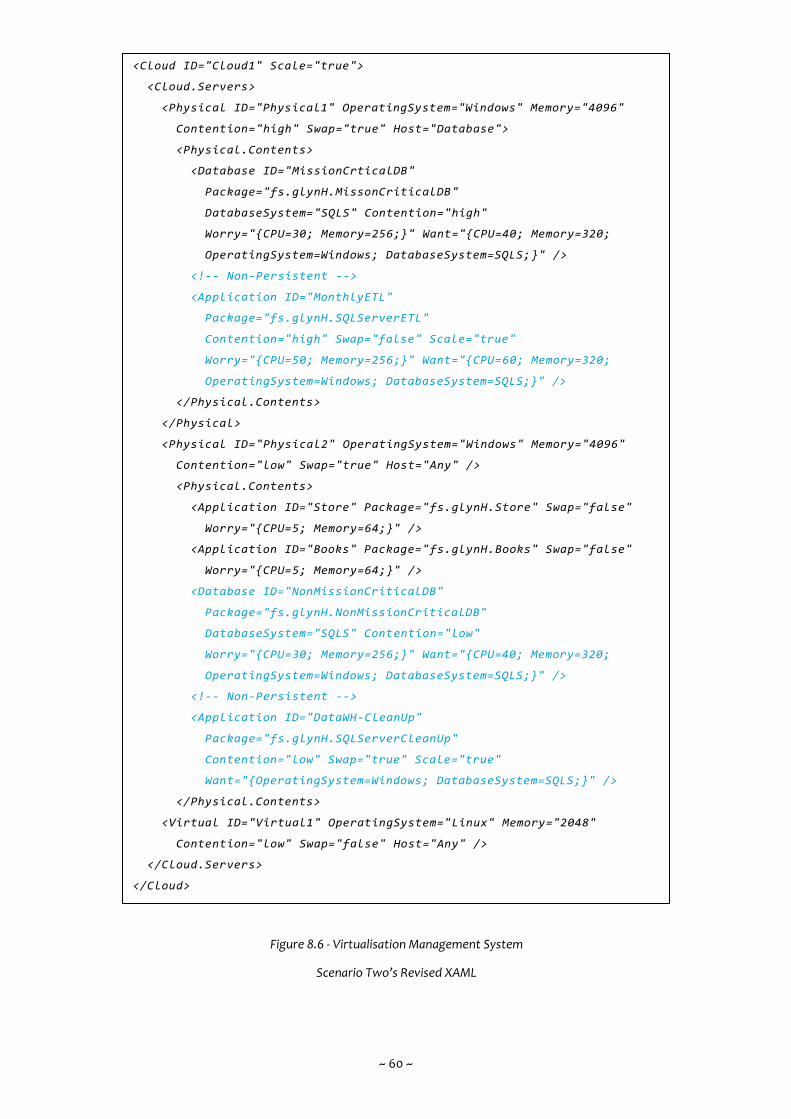
~ 60 ~
Figure 8.6 - Virtualisation Management System
Scenario Two’s Revised XAML
<Cloud ID="Cloud1" Scale="true">
<Cloud.Servers>
<Physical ID="Physical1" OperatingSystem="Windows" Memory="4096"
Contention="high" Swap="true" Host="Database">
<Physical.Contents>
<Database ID="MissionCrticalDB"
Package="fs.glynH.MissonCriticalDB"
DatabaseSystem="SQLS" Contention="high"
Worry="{CPU=30; Memory=256;}" Want="{CPU=40; Memory=320;
OperatingSystem=Windows; DatabaseSystem=SQLS;}" />
<!-- Non-Persistent -->
<Application ID="MonthlyETL"
Package="fs.glynH.SQLServerETL"
Contention="high" Swap="false" Scale="true"
Worry="{CPU=50; Memory=256;}" Want="{CPU=60; Memory=320;
OperatingSystem=Windows; DatabaseSystem=SQLS;}" />
</Physical.Contents>
</Physical>
<Physical ID="Physical2" OperatingSystem="Windows" Memory="4096"
Contention="low" Swap="true" Host="Any" />
<Physical.Contents>
<Application ID="Store" Package="fs.glynH.Store" Swap="false"
Worry="{CPU=5; Memory=64;}" />
<Application ID="Books" Package="fs.glynH.Books" Swap="false"
Worry="{CPU=5; Memory=64;}" />
<Database ID="NonMissionCriticalDB"
Package="fs.glynH.NonMissionCriticalDB"
DatabaseSystem="SQLS" Contention="low"
Worry="{CPU=30; Memory=256;}" Want="{CPU=40; Memory=320;
OperatingSystem=Windows; DatabaseSystem=SQLS;}" />
<!-- Non-Persistent -->
<Application ID="DataWH-CleanUp"
Package="fs.glynH.SQLServerCleanUp"
Contention="low" Swap="true" Scale="true"
Want="{OperatingSystem=Windows; DatabaseSystem=SQLS;}" />
</Physical.Contents>
<Virtual ID="Virtual1" OperatingSystem="Linux" Memory="2048"
Contention="low" Swap="false" Host="Any" />
</Cloud.Servers>
</Cloud>
~ 61 ~
Once complete the System Agent may firstly remove the MonthlyETL application from the Physical1 server as per the
agent node’s persist attribute (shown in the markup through commenting) and secondly, trigger the agent node
containing the DataWH-CleanUp application.
The DataWH-CleanUp application’s Want property is not fussy about its hosting operating system’s resource
availability beyond a compatible operating system and database system so can be attached to the low contention
Physical2 server. Once complete the System Agent may remove the DataWH-CleanUp application (again, shown in the
markup through commenting).
Both the relatively simple scenario and the more complex scenario pose yet more unanswered questions regarding
some of the actions being taken. Such a question is “does the VMS consolidate and compact the contents of unnecessarily
numerous servers (be they physical or virtual) once a period of turmoil has passed?” Specifically, the VMS could, in theory,
swap back the NonMissionCriticalDB database could (following events of scenario two) to the Physical1 server. The
answer to this questions lies not so much in the VMS but in adopting (via the System Agent) a periodic consolidate and
compact process.
8.5. Hypervisor Interaction
The use of hypervisors in cloud computing systems has been well documented [10] [11] [30]. As a viable proof of
concept the VMS needed to communicate with two or more hypervisors, preferably of differing types (e.g. Type-One
and Type-Two).
Being an application written in C# and utilizing the libraries of the Microsoft .NET 4 Framework, the VMS most logical
target was Microsoft’s Hyper-V [34], a proprietary 64-bit hypervisor for Windows Server 2008 onwards. This hypervisor
has its own management tools (largely manual in nature) that are able to communicate with the hypervisor through
Windows Communication Foundation (WCF) web services / remoting. With this WCF oriented infrastructure in place,
the VMS was able to communicate with Hyper-V through remoting calls in much the same way and with minimal
interoperability problems.
The next logical target was Oracle’s VirtualBox [37], a 32 / 64-bit hypervisor developed by Oracle, freely licensed under
the GNU General Public License. The VMS was able to communicate with VirtualBox though direct method calls using
Component Object Model (COM) interop with VirtualBox’s Dynamic Link Library (DLL).
Finally, to ease early development and testing, a dummy hypervisor was produced that would communicate with the
VMS through a WCF oriented infrastructure with attributes and operations characteristic of a light weight deployment
of Microsoft Hyper-V. While not able to fully emulate a hypervisor, the dummy allowed for proof of concept
development activity take place concerning hypervisor interaction.
~ 62 ~
8.5.1. Default System Image Repository
In order to support the mounting of guest operating systems and in unison, the necessary enterprise servers,
the VMS maintains a file system repository containing a suitably pre-configured default system image for any
anticipated role (e.g. a pre-configured Ubuntu Linux operating system with a pre-configured Oracle 12c database
system ready to go). Each default system image may then be mounted into a newly provisioned virtual machine
with any setup and configuration supporting the minimum amount of human interaction through an unattended
mode.
8.5.2. Package Deployment
Controlling the operations of the hypervisors is one problem (e.g. allocating more memory resources) and
controlling the operations of the guest operating systems is a quite distinct problem (e.g. swapping in the
GreedyDB database as shown in Figure 8.3). This requires direct administrative access to the guest operating
system, preferably with the minimum amount of human interaction. Fortunately most operating systems have a
native capability that allows software components to be deployed and removed through an unattended mode.
The various editions of the Windows operating system ship with Microsoft Installer packaging [58] while many
Linux distributions ship with either RPM packaging [59] or DEB packaging.
8.6. Human Interaction
The VMS was able to communicate with humans, the current system schema along with any advised changes,
through either declarative markup or Graphical User Interface (GUI). The GUI’s structure and operation is based on a
typical network diagram with a potentially unlimited number of layers, whose nodes can be drilled into so as to
decompose large components into their components and sub-components again and again. This allows for any view of
the system schema from the top level data centre architecture right down to the low level virtual machine contents.
Figure 8.7 shows a basic dashboard scenario, (representative of a small scale desktop environment / low level)
comprising two physical servers, the second of which is hosting three virtual servers, the first of which is hosting two
databases and an eXtensible Markup Language (XML) repository. As shown, by selecting each node the contents are
displayed in a hierarchy structure along with summary data regarding the selected node.
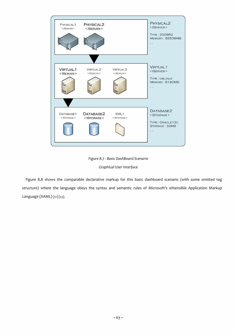
~ 63 ~
Figure 8.7 - Basic DashBoard Scenario
Graphical User Interface
Figure 8.8 shows the comparable declarative markup for this basic dashboard scenario (with some omitted tag
structure) where the language obeys the syntax and semantic rules of Microsoft’s eXtensible Application Markup
Language (XAML) [51] [53].
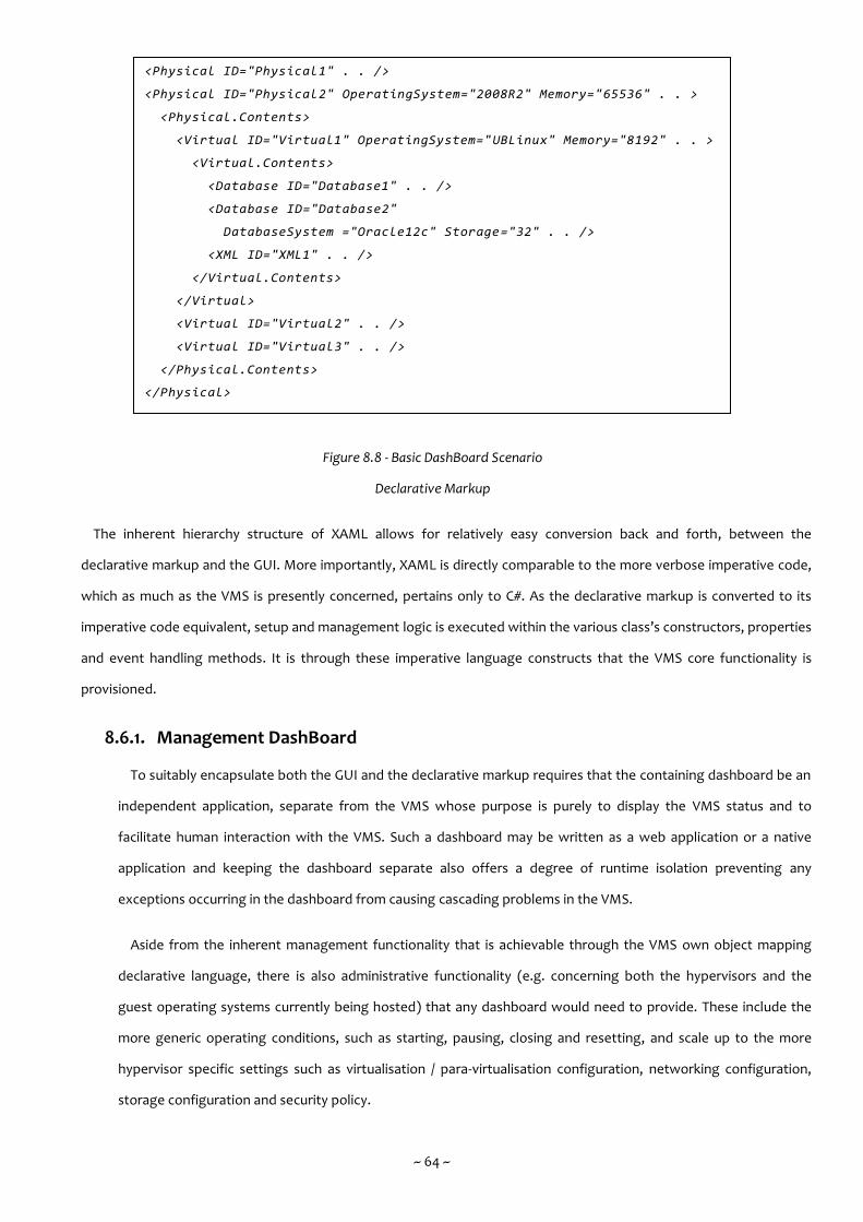
~ 64 ~
Figure 8.8 - Basic DashBoard Scenario
Declarative Markup
The inherent hierarchy structure of XAML allows for relatively easy conversion back and forth, between the
declarative markup and the GUI. More importantly, XAML is directly comparable to the more verbose imperative code,
which as much as the VMS is presently concerned, pertains only to C#. As the declarative markup is converted to its
imperative code equivalent, setup and management logic is executed within the various class’s constructors, properties
and event handling methods. It is through these imperative language constructs that the VMS core functionality is
provisioned.
8.6.1. Management DashBoard
To suitably encapsulate both the GUI and the declarative markup requires that the containing dashboard be an
independent application, separate from the VMS whose purpose is purely to display the VMS status and to
facilitate human interaction with the VMS. Such a dashboard may be written as a web application or a native
application and keeping the dashboard separate also offers a degree of runtime isolation preventing any
exceptions occurring in the dashboard from causing cascading problems in the VMS.
Aside from the inherent management functionality that is achievable through the VMS own object mapping
declarative language, there is also administrative functionality (e.g. concerning both the hypervisors and the
guest operating systems currently being hosted) that any dashboard would need to provide. These include the
more generic operating conditions, such as starting, pausing, closing and resetting, and scale up to the more
hypervisor specific settings such as virtualisation / para-virtualisation configuration, networking configuration,
storage configuration and security policy.
<Physical ID="Physical1" . . />
<Physical ID="Physical2" OperatingSystem="2008R2" Memory="65536" . . >
<Physical.Contents>
<Virtual ID="Virtual1" OperatingSystem="UBLinux" Memory="8192" . . >
<Virtual.Contents>
<Database ID="Database1" . . />
<Database ID="Database2"
DatabaseSystem ="Oracle12c" Storage="32" . . />
<XML ID="XML1" . . />
</Virtual.Contents>
</Virtual>
<Virtual ID="Virtual2" . . />
<Virtual ID="Virtual3" . . />
</Physical.Contents>
</Physical>
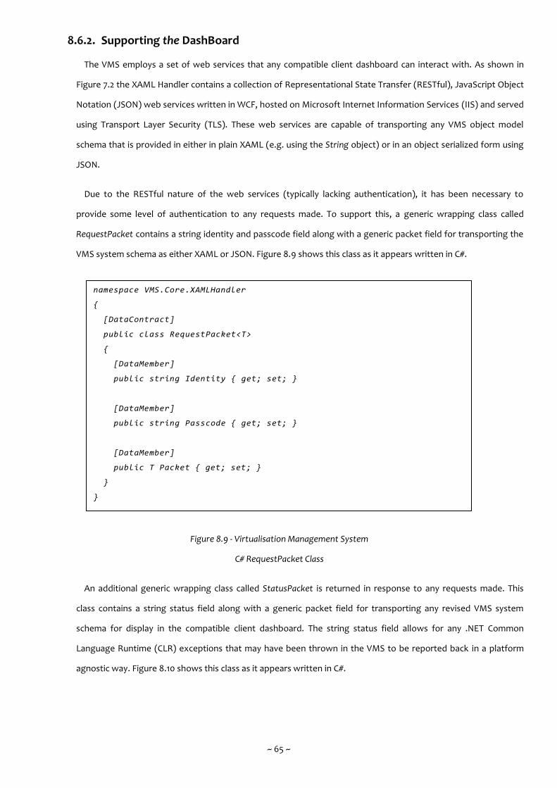
~ 65 ~
8.6.2. Supporting the DashBoard
The VMS employs a set of web services that any compatible client dashboard can interact with. As shown in
Figure 7.2 the XAML Handler contains a collection of Representational State Transfer (RESTful), JavaScript Object
Notation (JSON) web services written in WCF, hosted on Microsoft Internet Information Services (IIS) and served
using Transport Layer Security (TLS). These web services are capable of transporting any VMS object model
schema that is provided in either in plain XAML (e.g. using the String object) or in an object serialized form using
JSON.
Due to the RESTful nature of the web services (typically lacking authentication), it has been necessary to
provide some level of authentication to any requests made. To support this, a generic wrapping class called
RequestPacket contains a string identity and passcode field along with a generic packet field for transporting the
VMS system schema as either XAML or JSON. Figure 8.9 shows this class as it appears written in C#.
Figure 8.9 - Virtualisation Management System
C# RequestPacket Class
An additional generic wrapping class called StatusPacket is returned in response to any requests made. This
class contains a string status field along with a generic packet field for transporting any revised VMS system
schema for display in the compatible client dashboard. The string status field allows for any .NET Common
Language Runtime (CLR) exceptions that may have been thrown in the VMS to be reported back in a platform
agnostic way. Figure 8.10 shows this class as it appears written in C#.
namespace VMS.Core.XAMLHandler
{
[DataContract]
public class RequestPacket<T>
{
[DataMember]
public string Identity { get; set; }
[DataMember]
public string Passcode { get; set; }
[DataMember]
public T Packet { get; set; }
}
}
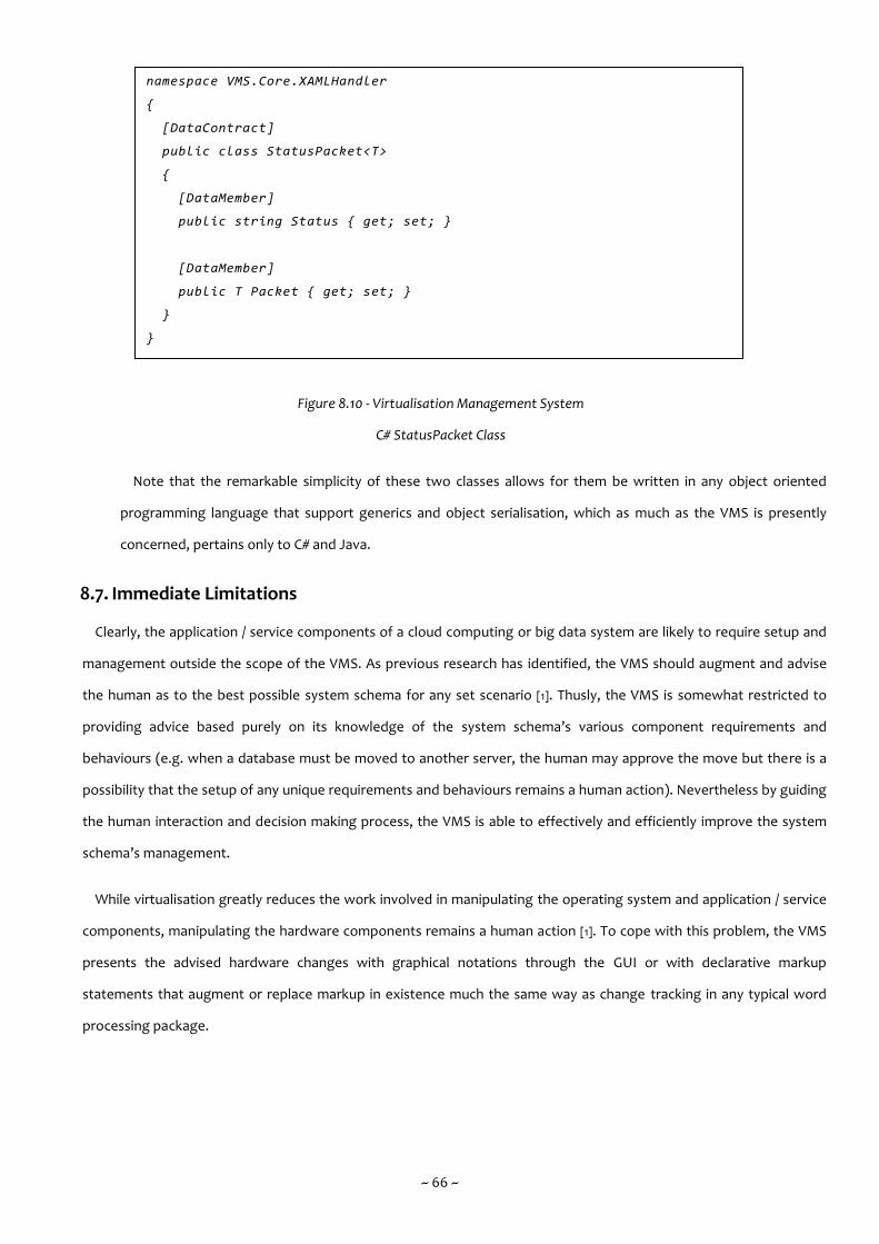
~ 66 ~
Figure 8.10 - Virtualisation Management System
C# StatusPacket Class
Note that the remarkable simplicity of these two classes allows for them be written in any object oriented
programming language that support generics and object serialisation, which as much as the VMS is presently
concerned, pertains only to C# and Java.
8.7. Immediate Limitations
Clearly, the application / service components of a cloud computing or big data system are likely to require setup and
management outside the scope of the VMS. As previous research has identified, the VMS should augment and advise
the human as to the best possible system schema for any set scenario [1]. Thusly, the VMS is somewhat restricted to
providing advice based purely on its knowledge of the system schema’s various component requirements and
behaviours (e.g. when a database must be moved to another server, the human may approve the move but there is a
possibility that the setup of any unique requirements and behaviours remains a human action). Nevertheless by guiding
the human interaction and decision making process, the VMS is able to effectively and efficiently improve the system
schema’s management.
While virtualisation greatly reduces the work involved in manipulating the operating system and application / service
components, manipulating the hardware components remains a human action [1]. To cope with this problem, the VMS
presents the advised hardware changes with graphical notations through the GUI or with declarative markup
statements that augment or replace markup in existence much the same way as change tracking in any typical word
processing package.
namespace VMS.Core.XAMLHandler
{
[DataContract]
public class StatusPacket<T>
{
[DataMember]
public string Status { get; set; }
[DataMember]
public T Packet { get; set; }
}
}
~ 67 ~
Once the changes have been made, the human must manually modify the hardware components in the VMS system
schema. In operation, this sequence of events was always going to prove somewhat problematic. The most
noteworthy problem has been that the time delay between the VMS advising hardware changes and the human action
actually being performed may be lengthy and may also demonstrate dangerously high variance. The consequence
being, that the VMS though its periodic analysis of the system schema, forgets the original reasoning behind modifying
the hardware components.
Attempts were made to cope with this problem by the use of a system generated job no. The VMS would optionally
use a unique job no to identify a specific set of advised hardware changes. No further action towards that scenario’s
solution would be undertaken by the VMS until the system schema was informed that the set of advised hardware
changes in the job no had been undertaken.
The problem was also partly addressed by allowing the human to lock certain sections of the system schema thereby
preventing the VMS from performing further analyses or suggestions within any locked sections. Once the human
action had been performed the lock would be removed and the VMS would be able to resume normally. A key
characteristic of the lock was an override value that specified which events, of varying severity, would be ignored (e.g.
a subtle system schema change) vs those which were able to override the lock (e.g. a serious resource shortage).
8.8. Automatic / Autonomic Support
The VMS employs a plug-in based mechanism to provide automatic / autonomic capability. As shown in Figure 7.2 the
Plug-in Manager is responsible for checking and invoking any decision making logic. This approach keeps the VMS
internal components separate from any decision making logic. Any such automatic / autonomic capability, whether it be
currently available or available in the future may be employed by the VMS through the use of an appropriately formed
.NET 4 Framework DLL. A developer need only ensure consistency with the various method signatures defined in the
programmatic interface of the Plug-in Manager and with the general compatibility of code that is aimed at managing
the differing systems and resources that are available to cloud computing or big data systems.
Selecting the .NET 4 Framework as the programmatic interface of the Plug-in Manager permits the use of any .NET
CLR compatible language. Given the likelihood that any such plug-in will be written using any practicable programming
paradigm with automatic / autonomic capability, such as functional and agent programming, it certainly makes sense to
fully support a multi-paradigm programming language from the very outset [57].
~ 68 ~
With regards to specific automatic / autonomic requirements, there has arisen an obvious distinction between those
that are proactive in nature and those that are reactive. A proactive requirement can be defined as a foreseeable
variance in the hardware / software components and the resources they require to effectively support a system’s
operations [60], a suitable example being an episodically observed (and thusly now predictable) change in demand for
an application / service. A reactive requirement can be defined as a response to a specific event that may or may not
draw on previous knowledge within the system [61], a suitable example being an unanticipated failure in a hardware /
software component.
The VMS is able to support both types of automatic / autonomic requirements, making changes to the hypervisors
that make up the cloud computing or big data systems either directly or where necessary through appropriate human
interaction and decision making.
8.9. Summary
This chapter’s priority has been to extend the previous chapter’s contents by bringing the VMS to life by way of two
scenarios, with each scenario demonstrating some core functionality as it attempts to solve specific problems that are
typical of the VMS operating domain. This chapter has also focussed on demonstrating the three key aspects of
external interaction that the VMS supports (namely the hypervisor, the human and the automatic / autonomic plug-in)
and by virtue, revealing the key findings of VMS and identifying areas of ongoing design and development that will
inform any future work.
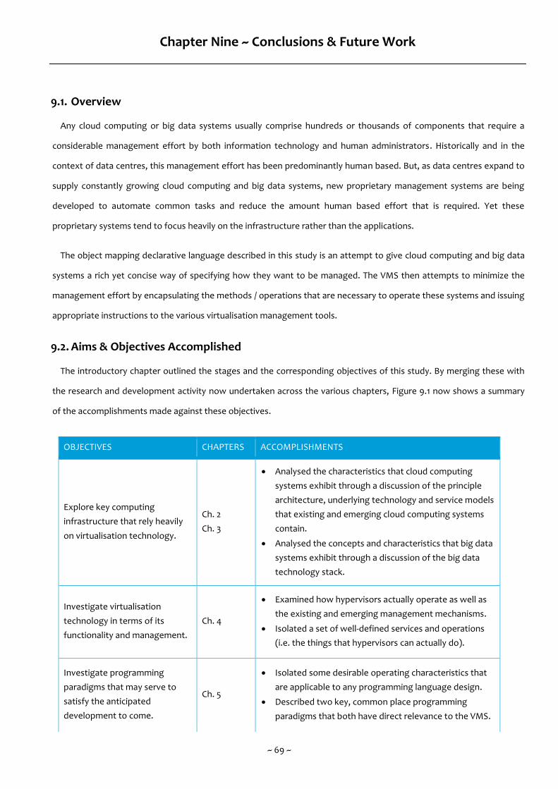
~ 69 ~
Chapter Nine ~ Conclusions & Future Work
9.1. Overview
Any cloud computing or big data systems usually comprise hundreds or thousands of components that require a
considerable management effort by both information technology and human administrators. Historically and in the
context of data centres, this management effort has been predominantly human based. But, as data centres expand to
supply constantly growing cloud computing and big data systems, new proprietary management systems are being
developed to automate common tasks and reduce the amount human based effort that is required. Yet these
proprietary systems tend to focus heavily on the infrastructure rather than the applications.
The object mapping declarative language described in this study is an attempt to give cloud computing and big data
systems a rich yet concise way of specifying how they want to be managed. The VMS then attempts to minimize the
management effort by encapsulating the methods / operations that are necessary to operate these systems and issuing
appropriate instructions to the various virtualisation management tools.
9.2. Aims & Objectives Accomplished
The introductory chapter outlined the stages and the corresponding objectives of this study. By merging these with
the research and development activity now undertaken across the various chapters, Figure 9.1 now shows a summary
of the accomplishments made against these objectives.
OBJECTIVES CHAPTERS ACCOMPLISHMENTS
Explore key computing
infrastructure that rely heavily
on virtualisation technology.
Ch. 2
Ch. 3
Analysed the characteristics that cloud computing
systems exhibit through a discussion of the principle
architecture, underlying technology and service models
that existing and emerging cloud computing systems
contain.
Analysed the concepts and characteristics that big data
systems exhibit through a discussion of the big data
technology stack.
Investigate virtualisation
technology in terms of its
functionality and management.
Ch. 4
Examined how hypervisors actually operate as well as
the existing and emerging management mechanisms.
Isolated a set of well-defined services and operations
(i.e. the things that hypervisors can actually do).
Investigate programming
paradigms that may serve to
satisfy the anticipated
development to come.
Ch. 5
Isolated some desirable operating characteristics that
are applicable to any programming language design.
Described two key, common place programming
paradigms that both have direct relevance to the VMS.
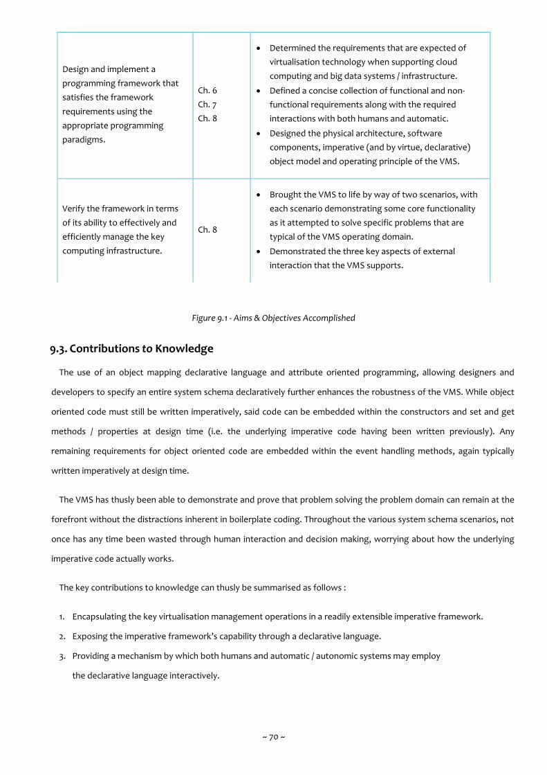
~ 70 ~
Figure 9.1 - Aims & Objectives Accomplished
9.3. Contributions to Knowledge
The use of an object mapping declarative language and attribute oriented programming, allowing designers and
developers to specify an entire system schema declaratively further enhances the robustness of the VMS. While object
oriented code must still be written imperatively, said code can be embedded within the constructors and set and get
methods / properties at design time (i.e. the underlying imperative code having been written previously). Any
remaining requirements for object oriented code are embedded within the event handling methods, again typically
written imperatively at design time.
The VMS has thusly been able to demonstrate and prove that problem solving the problem domain can remain at the
forefront without the distractions inherent in boilerplate coding. Throughout the various system schema scenarios, not
once has any time been wasted through human interaction and decision making, worrying about how the underlying
imperative code actually works.
The key contributions to knowledge can thusly be summarised as follows :
1. Encapsulating the key virtualisation management operations in a readily extensible imperative framework.
2. Exposing the imperative framework’s capability through a declarative language.
3. Providing a mechanism by which both humans and automatic / autonomic systems may employ
the declarative language interactively.
Design and implement a
programming framework that
satisfies the framework
requirements using the
appropriate programming
paradigms.
Ch. 6
Ch. 7
Ch. 8
Determined the requirements that are expected of
virtualisation technology when supporting cloud
computing and big data systems / infrastructure.
Defined a concise collection of functional and non-
functional requirements along with the required
interactions with both humans and automatic.
Designed the physical architecture, software
components, imperative (and by virtue, declarative)
object model and operating principle of the VMS.
Verify the framework in terms
of its ability to effectively and
efficiently manage the key
computing infrastructure.
Ch. 8
Brought the VMS to life by way of two scenarios, with
each scenario demonstrating some core functionality
as it attempted to solve specific problems that are
typical of the VMS operating domain.
Demonstrated the three key aspects of external
interaction that the VMS supports.

~ 71 ~
9.4. Research & Development Constraints
During the research and development activity there were various, predominantly technical constraints encountered.
9.4.1. Access only to Local Servers
Not surprisingly, access to any data centre, be it operating in an industry or research setting, is typically highly
restrictive and even when not, likely still costly. As such, the VMS has currently only communicated with a testing
environment containing three physical servers, each in turn, containing up to five virtual servers. Future research
and development activity is likely to require a testing environment more representative of the use of
virtualisation in large scale data centre infrastructure. With such an environment available, the VMS could be put
through its paces properly, though acting as a principle of many, it is likely a single physical machine could
perform the VMS processing work alone.
9.4.2. Long Term Data Storage / Archiving
With the exception of the numerous saved system schema in play by the VMS at any specific moment and the
saved system schema that may be retrieved / employed by the System Agent, the VMS currently has no provision
of long term data storage / archiving. Future research and development activity may give rise to a situation
whereby components not in play or snippets of a system schema may need some degree of non-volatile, long
term data storage / archiving.
9.4.3. Exception Handling
There is currently no provision within the VMS for capturing and handling exceptions that might be thrown by
the host operating systems, the hypervisors or the guest operating systems currently being hosted. Such
provision would require an additional sub-system within the VMS that is able to parse the appropriate error logs
(e.g. when Hyper-V writes its error logs to the Windows Event Logging service running on Hyper-V’s host
operating system).
In addition, any corrective action would require interaction with the human or the automatic / autonomic
system so as to resolve any exceptions. As shown in Figure 7.4 and as discussed in Section 7.5 this would require
changes to the VMS . Entity objects within the current system schema before re-employing the revised system
schema.
9.5. Future Work
Due to the considerable scope of virtualisation management operations that the VMS could conceivably encapsulate,
the discussion concerning future work is a whole sub-section in its own right, with each significant component / sub-
component of the VMS containing areas that could potentially be augmented or extended.
~ 72 ~
9.5.1. Autonomic Capability
The term autonomic computing was, in its genesis an IBM initiative, the goals of which were to develop
information technology systems that are capable of self-management [62]. The initiative argues that autonomic
computing can overcome the growing complexity of information technology systems, a trend that might pose
problems to further growth.
Given the inevitable scale of cloud computing or big data systems, the use of autonomic systems in the
management problem is inherently favourable. While a human control centre can regulate every aspect of the
physical and virtual servers, many tasks can be performed by autonomic systems with suitable awareness of the
operating environment. But, despite the apparent case for autonomic systems, they are ultimately only
comparable to humans in that they are merely management users of cloud computing or big data systems.
Future research and development activity will focus firstly on the plug-in manager, specifically when the VMS
attempts to make changes, or when restrictions are in place, attempts to derive an alternative strategy. These
aspects require the autonomic aspects of the VMS to function fully and the goal is (as with any autonomic
system) to make sound decisions based on the available system schema data.
9.5.2. Interoperability
An additional area of concern the VMS own interoperability interface, with interoperability currently being
achieved through Windows Communication Foundation (WCF) web services / remoting method calls and
Component Object Model (COM) interop method calls. Future research and development activity will thusly
focus on extending the influence that the VMS has over additional hypervisors such as VMware ESXi.
There is also scope to allow the VMS to integrate with existing proprietary management systems such as
Microsoft’s AutoPilot [12] and Canonical’s OpenStack AutoPilot [13]. This is possible because both systems expose
a suitable interoperability interface.
9.5.3. Visualisation
While the current DashBoard may provide a practicable Graphical User Interface (GUI) through which the VMS
may communicate with humans, it is somewhat inflexible and two dimensional. Given the hierarchy structure of
any system schema, it is certainly plausible to introduce a more flexible and three dimensional DashBoard. An
extreme version could even embed geographical data regarding the data centre’s physical layout in the object
model, thusly allowing for fully immersive, visualised, walk through environments.

~ 73 ~
9.6. Concluding Remarks
The early genesis of the VMS was nothing more than a proof of concept, programmatic experiment into using
Component Object Model (COM) interop from the .NET 4 Framework to control hypervisors such as Oracle’s
VirtualBox. When that proved to be a success, the experiment was expanded to incorporate a newly released object
mapping declarative language from Microsoft, what would ultimately become called eXtensible Application Markup
Language (XAML).
Figure 9.2 shows the very first architecture diagram (circa 2009) for the then (perhaps improperly) labelled Cloud
Computing Management System (CCMS). The CCMS was similarly, nothing more than a proof of concept to determine
at a very basic level if the given research & development question was even practicable. As it turned out, a single virtual
machine could be defined in XAML, parsed by the CCMS’s Control System and then spawned by Oracle’s VirtualBox
following direct method calls to the appropriate Dynamic Link Library (DLL).
Figure 9.2 - The Very First Architecture Diagram
Many design thoughts and development activities have changed and more than a few years on, the CCMS has
evolved into the VMS which is now a much more capable control system with plenty more research and development
activity still to come. It is thusly not unreasonable to say that the VMS internal components are almost as extensible as
the object oriented nature of its imperative and declarative programming language.
~ 74 ~
References
[1] Mladen A. Vouk, Computer Science, North Carolina State University, USA, 2008.
“Cloud Computing - Issues, Research & Implementations”.
[2] Chang, et al, Intel Incorporation, SOSE 2006, Second IEEE International Workshop,
“Service-Orientation in the Computing Infrastructure”.
[3] Abhijit Dubey, The McKinsey Quarterly, May 2007,
“Delivering Software as a Service”.
http://ai.kaist.ac.kr/~jkim/cs489-2007/Resources/DeliveringSWasaService.pdf
[4] KIT Software Quality Department. August 2011,
“Defining and Measuring Cloud Elasticity”.
[5] Rajkumar Buyya, et al, GRIDS Laboratory, Computer Science & Software Engineering, Melbourne University, Australia, July 2008,
“Market-Oriented Cloud Computing : Vision, Hype & Reality for Delivering IT Services as Computing Utilities”.
[6] Michael Armbrust, Electrical Engineering & Computer Sciences, Berkeley University, California, 2009,
“Above the Clouds: A Berkeley View of Cloud Computing”.
http://www.eecs.berkeley.edu/Pubs/TechRpts/2009/EECS-2009-28.html
[7] Sumalatha Adabala, et al, Future Generation Computer Systems 21, January 2005,
“From Virtualized Resources to Virtual Computing Grids : The In-VIGO System”.
[8] George Lawton, The IEEE Computer Society, Volume 41, Issue 6, June 2008,
“Developing Software Online with Platform as a Service Technology”.
[9] Sushil Bhardwaj, et al, International Journal of Engineering and Information Technology, India, July 2010,
“Cloud Computing : A Study of Infrastructure as a Service (IAAS)”.
[10] Rich Uhlig, et al, The IEEE Computer Society, Volume 38, Issue 5, May 2005,
“Intel Virtualization Technology”.
[11] Keith Adams, Ole Agesen, VMware, 12th International Conference on Architectural Support for Programming Languages & Operating Systems, 2006,
“A Comparison of Software and Hardware Techniques for x86”.
[12] Michael Isard, Microsoft Research, ACM SIGOPS Operating Systems Review, Volume 41, Issue 2, April 2007,
“AutoPilot: Automatic Data Centre Management”.
[13] OpenStack Autopilot, Canonical Limited, Retrieved May 2015.
~ 75 ~
http://www.ubuntu.com/cloud/openstack/autopilot/
[14] Kapil Bakshi, Aerospace Conference IEEE, Jan 2012,
“Considerations for Big Data : Architecture & Approach”.
[15] Mark van Rijmenam, DataFloQ, Retrieved May 2015,
“Why the 3 V’s are not sufficient to describe Big Data”.
https://datafloq.com/read/3vs-sufficient-describe-big-data/166
[16] Database Data WareHousing Guide, Oracle, Retrieved April 2016.
https://docs.oracle.com/cd/B19306_01/server.102/b14223/aggreg.htm
[17] Barzan Mozafari, et al, 2013 ACM SIGMOD International Conference on Management of Data, June 2013,
“Performance and Resource Modelling in Highly-Concurrent OLTP Work Loads”.
[18] Shaker H. Ali El-Sappagh, et al, Journal of King Saud University - Computer and Information Sciences, Volume 23, Issue 2, July 2011,
“A Proposed Model for Data WareHousing ETL Processes”.
[19] Alfredo Cuzzocrea, et al, 16th International Workshop on Data WareHousing and OLAP, October 2013,
“Data WareHousing and OLAP over Big Data: Current Challenges and Future Research Directions”.
[20] Overview of SQL Server in a SharePoint Environment. Microsoft, Retrieved July 2015.
https://technet.microsoft.com/en-us/library/ff945791.aspx
[21] Alfredo Cuzzocrea, IEEE 37th Annual Computer Software and Applications Conference, May 2013,
“Analytics over Big Data : Exploring the Convergence of Data WareHousing, OLAP and Data-Intensive Cloud Infrastructure”.
[22] SQL Server Reporting Services, Microsoft, Retrieved July 2015.
https://msdn.microsoft.com/en-us/library/ms159106(v=sql.105).aspx
[23] V. Mauch, et al, PCaPAC, Germany, Sep 2014,
“OpenGL - Based Data Analysis in Virtualized Self-Service Environments”.
[24] Always On Failover Cluster Instances (SQL Server), Microsoft, Retrieved May 2016.
https://msdn.microsoft.com/en-us/library/ms189134.aspx
[25] Jeffrey Dean, Sanjay Ghemawat, Communications of the ACM, Volume 53, Issue 1, January 2010,
“MapReduce : A Flexible Data Processing Tool”.
[26] Rochwerger et al, Future Internet Assembly, April 2009,
“Design for Future Internet Service Infrastructures”.
~ 76 ~
[27] Wine Developer's Guide, WineHQ, Retrieved August 2016.
https://wiki.winehq.org/Wine_Developer's_Guide
[28] Langner T, Schindelhauer C, Souza A, SOFSEM 2011 : Theory and Practice of Computer Science,
“Optimal File Distribution in Heterogeneous and Asymmetric Storage Networks”.
[29] N. M. Mosharaf, et al, University of Waterloo, IEEE Communications Magazine, Volume 47, Issue 7, July 2009,
“Network Virtualization : State of the Art and Research Challenges”.
[30] Jose Renato Santos, et al, Cambridge University, UK, 2008 - USENIX Annual Tech Conference,
“Bridging the Gap between Software & Hardware Techniques for I/O Virtualization”.
[31] Intel Virtualisation Technology, Intel ARK, Retrieved Dec 2014.
http://ark.intel.com/Products/VirtualizationTechnology
[32] AMD Client Virtualization, AMD, Retrieved Dec 2014.
http://www.amd.com/en-gb/solutions/pro/virtualization
[33] Michael Fenn, et al, 2nd International Conference on the Virtual Computing Initiative, USA, 2008,
“An Evaluation of KVM for Use in Cloud Computing”.
[34] Server 2008 R2 Virtualization, Microsoft, Retrieved May 2010.
http://www.microsoft.com/windowsserver2008/en/us/hyperv-main.aspx
[35] VMware ESXi, VMware, Retrieved June 2016.
http://www.vmware.com/products/esxi-and-esx/
[36] Graziano Charles, Iowa State University, August 2011,
“A performance analysis of Xen and KVM hypervisors for hosting the Xen Worlds Project”.
[37] VirtualBox Technical Documentation, Oracle, Retrieved May 2011.
http://www.virtualbox.org/wiki/technical_documentation
[38] VMware Workstation Pro, VMware, Retrieved June 2016.
http://www.vmware.com/products/workstation/
[39] Hyper-V Architecture and Feature Overview, Microsoft, Retrieved June 2016.
https://msdn.microsoft.com/en-us/library/dd722833(BTS.10).aspx
[40] Linux Integration Services Version 4.0 for Hyper-V, Microsoft, Retrieved July 2016.
https://www.microsoft.com/en-us/download/details.aspx?id=46842
~ 77 ~
[41] Yutaka Haga, et al, Fujitsu Scientific & Technical Journal 47, July 2011,
“Windows Server 2008 R2 Hyper-V Server Virtualisation”.
[42] Hyper-V WMI Classes, Microsoft, Retreived Jan 2016.
https://msdn.microsoft.com/en-us/library/hh850078(v=vs.85).aspx
[43] Windows Management Infrastructure (MI), Microsoft, Retreived Jan 2016.
https://msdn.microsoft.com/en-us/library/jj152383(v=vs.80).aspx
[44] Hyper-V Cmdlets in Windows PowerShell, Microsoft, Retreived Jan 2016.
https://technet.microsoft.com/en-us/library/hh848559(v=wps.630).aspx
[45] Virtual Machine Manager, Microsoft, Retrieved Jan 2016.
https://technet.microsoft.com/en-us/library/gg610610(v=sc.12).aspx
[46] Tatsuru Matsushita, University of York, Oct 1998,
“Expressive Power of Declarative Programming Languages”.
[47] C# Language Specification, Microsoft, Retrieved May 2016.
https://msdn.microsoft.com/en-us/library/ms228593.aspx
[48] F# Language Specification, F# Software Foundation, Retrieved May 2016.
http://fsharp.org/specs/language-spec/
[49] Java Language and Virtual Machine Specifications, Oracle, Retrieved May 2016.
https://docs.oracle.com/javase/specs/
[50] David Chu, et al, EECS Computer Science Division, University of California, Jan 2007,
“The Design and Implementation of a Declarative Sensor Network System”.
[51] XAML Overview, MSDN Library, Microsoft, Retrieved July 2011.
http://msdn.microsoft.com/en-us/library/ms752059.aspx
[52] Xamarin API Reference, Xamarin, Retrieved May 2016.
https://developer.xamarin.com/api/
[53] [MS-XAML-2012] : XAML Object Mapping Specification, Microsoft, Retrieved May 2015.
https://msdn.microsoft.com/en-us/library/hh857629.aspx
[54] Rouvoy Romain, Merle Philipp, 11th ECOOP International Workshop on Component-Oriented Programming, 2006,
“Leveraging Component-Oriented Programming with Attribute-Oriented Programming”.
~ 78 ~
[55] Ruska Štefan, Porubän Jaroslav, Acta Electrotechnica et Informatica, Volume 10, No 4, May 2010,
“Defining Annotation Constraints in Attribute Oriented Programming”.
[56] Attributes (C#), Microsoft, Retrieved July 2016.
https://msdn.microsoft.com/en-us/library/mt653979.aspx
[57] Elvira Albert, et al, Journal of Symbolic Computation, Volume 40, Issue 1, July 2005,
“Operational Semantics for Declarative Multi-Paradigm Languages”.
[58]] Overview of Windows Installer, Microsoft, Retrieved Oct 2015.
https://msdn.microsoft.com/en-us/library/aa370566(v=vs.85).aspx
[59] RPM Package Manager (RPM), Red Hat Linux, Retrieved Oct 2015.
http://www.rpm.org/
[60] David M. Chess, Alla Segal, Ian Whalley, Steve R. White, IBM, Thomas J. Watson Research Centre, 2004,
“Unity : Experiences with a Prototype Autonomic Computing System”.
[61] IBM Autonomic Computing, IBM, Retrieved July 2008.
http://www-01.IBM.Com/Software/tivoli/autonomic/pdfs/ac_blueprint_white_paper_4th.pdf
[62] Jeffrey Kephart, David Chess, The IEEE Computer Society, January 2003,
“The vision of Autonomic Computing”.