d2.32 - specification of the infrastructure virtualisation ... · infrastructure virtualisation,...
TRANSCRIPT
T-NOVA | Deliverable D2.32 Specification of the Infrastructure Virtualisation, Management and Orchestration - Final
© T-NOVA Consortium
1
Deliverable D2.32
Specification of the Infrastructure Virtualisation, Management and Orchestration - Final
Editor Michael J. McGrath (INTEL)
Contributors Vincenzo Riccobene (INTEL), Pedro Neves, José Bonnet, Jorge Carapinha, Antonio Gamelas (PTIN), Dora Christofi, Georgios Dimosthenous (PTL), Beppe Coffano, Luca Galluppi, Pierangelo Magli, Marco Di Girolamo (HP), Letterio Zuccaro, Federico Cimorelli, Roberto Baldoni (CRAT), George Xilouris, Eleni Trouva, Akis Kourtis (NCSRD), Zdravko Bozakov, Panagiotis Papadimitriou (LUH), Jordi Ferrer Riera (i2CAT), Piyush Harsh, Irena Trajkovska (ZHAW), Kimon Karras (FINT), Paolo Comi (ITALTEL)
Version 1.0
Date October 28th, 2015
T-NOVA | Deliverable D2.32 Specification of the Infrastructure Virtualisation, Management and Orchestration - Final
© T-NOVA Consortium
2
Executive Summary The specification presented in this document represents the final version for the Infrastructure Virtualisation, Management and Orchestration layers of the T-NOVA system. This specification utilises the requirements described in previous deliverables together with the latest Network Functions Virtualisation (NFV) and virtualisation requirements defined by various industry bodies including the ETSI ISG NFV and ITU-T, as well as excerpts of relevant parts of the ETSI ISG MANO WG architecture and associated Functional Entities (FEs). The concepts of virtualisation and NFV/SDN have a key influence on the design and implementation of the Infrastructure Virtualisation, Management and Orchestration layers. These approaches have respective pros and cons of both in the context of the T-NOVA system. The Orchestration and Infrastructure Virtualisation and Management (IVM) layers build these concepts to create a functional architecture that forms a key constituent of the overall T-NOVA system architecture.
The relationship between the T-NOVA Orchestrator and the NFV paradigm plays a key role in its design. The Orchestrator needs to address the challenges associated with the delivery of a suitable solution to support the deployment and management of virtualised network services (NS). The elucidation of associated functional requirements plays a key role in helping to addresses these challenges. Categorising the requirements also helps in ensuring a suitable level of granularity which makes sure all aspects of system functionality are appropriately captured and documented. These requirements are then used to identify system components such as interfaces, catalogues etc. and their associated functionalities.
The IVM layer is responsible to the provisioning and management of the infrastructure which provides the execution environment for T-NOVA’s network services. The overall design of the layer is driven by a variety of requirements such as performance, elasticity etc. The IVM layer is comprised of the Network Functions Virtualised Infrastructure (NFVI), Virtual Infrastructure Manager (VIM) and WAN Infrastructure Connection Manager (WICM) functional entities which are linked together with the other T-NOVA system components through various internal and external interfaces. The NFVI is comprised of compute, hypervisor and network constituent domains whose objectives and requirements need to be carefully considered in the context of the overall IVM design and implementation. With any architectural design it is important to interrogate it in order to determine if the design appropriately supports its associated requirements and design goals. The reference architectures for the IVM and Orchestration layers were interrogated and validated at a functional level through the development of NS and virtualised network function (VNF) sequence diagrams. These workflow diagrams illustrate the key actions and interactions within the layers during standard operational activities related to the deployment and management of VNF’s and NSs. In the design and implementation of any sophisticated system, gaps in available technologies will almost certainly emerge. If significant these gaps afford opportunities for new research and innovation. A focused gap analysis was carried out to determine the current technology gaps which affect the T-NOVA system together with potential steps to address them.
T-NOVA | Deliverable D2.32 Specification of the Infrastructure Virtualisation, Management and Orchestration - Final
© T-NOVA Consortium
3
Table of Contents
1. INTRODUCTION ........................................................................................................ 8
1.1. VIRTUALISATION ................................................................................................................................. 81.1.1 The Virtualisation Concept ......................................................................................... 81.1.2 The Pros and Cons of NFV Deployments ............................................................. 10
1.2 THE T-NOVA SOLUTION ......................................................................................................... 111.2.1 The T-NOVA Orchestration Platform (PTIN) ...................................................... 121.2.2 The T-NOVA IVM Platform ....................................................................................... 13
2. THE T-NOVA ORCHESTRATION LAYER ............................................................... 15
2.1. ORCHESTRATION LAYER OVERVIEW ............................................................................................. 152.2. ORCHESTRATOR REQUIREMENTS .................................................................................................. 18
2.2.1. NFVO Requirements Types .............................................................................................. 182.2.1.1. NS Lifecycle ...................................................................................................................................................... 192.2.1.2. VNF Lifecycle ................................................................................................................................................... 202.2.1.3. Resource Handling ........................................................................................................................................ 202.2.1.4. Monitoring Process ....................................................................................................................................... 212.2.1.5. Connectivity Handling ................................................................................................................................. 212.2.1.6. Policy Management ...................................................................................................................................... 222.2.1.7. Marketplace-specific Interactions ........................................................................................................... 22
2.2.2. VNFM Requirements Types .............................................................................................. 232.2.2.1. VNF Lifecycle ................................................................................................................................................... 232.2.2.2. Monitoring Process ....................................................................................................................................... 23
2.3. FUNCTIONAL ORCHESTRATOR ARCHITECTURE ........................................................................... 232.3.1. Reference Architecture ...................................................................................................... 242.3.2. Functional Entities .............................................................................................................. 25
2.3.2.1. Network Function Virtualisation Orchestrator (NFVO) ................................................................... 252.3.2.2. Virtual Network Function Manager (VNFM) ....................................................................................... 292.3.2.3. Repositories and Catalogues ..................................................................................................................... 30
2.3.3. External Interfaces .............................................................................................................. 312.3.3.1. Interface between the Orchestrator and the Network Function Store ..................................... 322.3.3.2. Interface between the Orchestrator and the Marketplace ............................................................ 332.3.3.3. Interface between the Orchestrator and the VIM ............................................................................. 332.3.3.4. Interface between the Orchestrator and the Transport Network Management ................... 342.3.3.5. Interface between the Orchestrator and the VNF ............................................................................. 35
3. THE T-NOVA IVM LAYER ....................................................................................... 36
3.1. INTRODUCTION .......................................................................................................................... 363.2. OBJECTIVES AND CHARACTERISTICS OF THE T-NOVA IVM LAYER ........................ 373.3. T-NOVA IVM LAYER REQUIREMENTS ................................................................................. 383.4. VIRTUAL INFRASTRUCTURE MANAGER (VIM) ............................................................................. 39
3.4.1. WAN Infrastructure Connection Manager ................................................................. 403.4.2. NFVI Compute ..................................................................................................................... 403.4.3. NFVI Hypervisor .................................................................................................................. 403.4.4. NFVI DC Network ............................................................................................................... 40
3.5. T-NOVA IVM ARCHITECTURE ..................................................................................................... 413.5.1. External Interfaces .............................................................................................................. 413.5.2. Internal IVM Interfaces ...................................................................................................... 44
T-NOVA | Deliverable D2.32 Specification of the Infrastructure Virtualisation, Management and Orchestration - Final
© T-NOVA Consortium
4
3.6. NFVI AND NFVI-POP ................................................................................................................... 463.6.1. IT Resources .......................................................................................................................... 47
3.6.1.1. Compute Domain .......................................................................................................................................... 473.6.1.2. Hypervisor Domain ....................................................................................................................................... 51
3.6.2. Infrastructure Network Domain ..................................................................................... 533.7. VIRTUALISED INFRASTRUCTURE MANAGEMENT ......................................................................... 54
3.7.1. IT Resource Management and Monitoring ................................................................. 563.7.1.1. Hypervisor Management ............................................................................................................................ 563.7.1.2. Computing Resources Management ..................................................................................................... 57
3.7.2. Infrastructure Network Resources Management and Monitoring ...................... 583.8. WAN INFRASTRUCTURE CONNECTION MANAGER .................................................................... 593.9. WICM: CONNECTING VNFS TO THE WAN ............................................................................... 61
3.9.1.1. SDN-enabled Network Elements ............................................................................................................. 623.9.1.2. Legacy Network Elements .......................................................................................................................... 62
4 T-NOVA VNFS AND NSS PROCEDURES ........................................................... 64
4.1 VNF RELATED PROCEDURES ..................................................................................................... 644.1.1 On-boarding .................................................................................................................. 644.1.2 Instantiation ................................................................................................................... 654.1.3 Monitoring ...................................................................................................................... 694.1.4 Scale-out ......................................................................................................................... 704.1.5 Termination .................................................................................................................... 71
4.2 NS RELATED PROCEDURES ....................................................................................................... 744.2.1 On-boarding .................................................................................................................. 744.2.2 Instantiation ................................................................................................................... 754.2.3 WAN Connections ........................................................................................................ 784.2.4 Supervision ..................................................................................................................... 784.2.5 Scale-out ......................................................................................................................... 804.2.6 Termination .................................................................................................................... 83
4.3 NS, VNF AND INFRASTRUCTURE MONITORING ................................................................... 83
5 GAP ANALYSIS .................................................................................................... 87
5.1 COMPUTE ................................................................................................................................... 875.2 HYPERVISOR ............................................................................................................................... 885.3 SDN CONTROLLERS .................................................................................................................. 895.4 CLOUD CONTROLLERS .............................................................................................................. 895.5 NETWORK VIRTUALISATION ..................................................................................................... 905.6 NFV ORCHESTRATOR ............................................................................................................... 92
6 CONCLUSIONS .................................................................................................... 94
ANNEX A - ORCHESTRATOR REQUIREMENTS ........................................................ 96
A.1 INTERNAL REQUIREMENTS ........................................................................................................ 97A.1.1 NFVO Requirements .................................................................................................... 97
A.1.1.1 NS Lifecycle requirements .................................................................................................................. 97A.1.1.2 VNF Lifecycle requirements ................................................................................................................ 98A.1.1.3 Resource Handling Requirements ................................................................................................... 99A.1.1.4 Monitoring Process requirements ................................................................................................. 100A.1.1.5 Connectivity Handling requirements ............................................................................................ 100A.1.1.7 Marketplace-specific interactions requirements ...................................................................... 101
T-NOVA | Deliverable D2.32 Specification of the Infrastructure Virtualisation, Management and Orchestration - Final
© T-NOVA Consortium
5
A.1.2 VNFM Requirements ................................................................................................ 101A.1.2.1 VNF Lifecycle requirements .............................................................................................................. 101A.1.2.2 Monitoring Process requirements ................................................................................................. 102
A.2 INTERFACE REQUIREMENTS .................................................................................................... 103A.2.1 Interface with VIM ..................................................................................................... 103A.2.2 Interface with VNF .................................................................................................... 105A.2.3 Interface with Marketplace .................................................................................... 106
ANNEX B - VIRTUALISED INFRASTRUCTURE MANAGEMENT REQUIREMENTS 108
B.1 VIRTUAL INFRASTRUCTURE MANAGEMENT REQUIREMENTS ............................................. 108B.2 WAN INFRASTRUCTURE CONNECTION MANAGER REQUIREMENTS ............................... 111B.3 NFV INFRASTRUCTURE REQUIREMENTS ............................................................................... 112
B.3.1 Computing ................................................................................................................... 112B.3.2 Hypervisor .................................................................................................................... 114B.3.3 Networking .................................................................................................................. 115
ANNEX C - TERMINOLOGY ..................................................................................... 118
C.1 GENERAL TERMS ...................................................................................................................... 118C.2 ORCHESTRATION DOMAIN .................................................................................................... 118C.3 IVM DOMAIN .......................................................................................................................... 119
LIST OF ACRONYMS ................................................................................................. 120
REFERENCES .............................................................................................................. 126
T-NOVA | Deliverable D2.32 Specification of the Infrastructure Virtualisation, Management and Orchestration - Final
© T-NOVA Consortium
6
Index of Figures
Figure 1-1 High-level view of overall T-NOVA System Architecture .................................. 12Figure 2-1: NSs and VNFs Complex Orchestration Overview ................................................ 16Figure 2-2: T-NOVA Orchestrator Reference Architecture ..................................................... 24Figure 2-3: NS Orchestrator (Internal & External) Interactions ............................................. 27Figure 2-4: Virtualised Resources Orchestrator (Internal & External) Interactions ....... 28Figure 2-5: VNF Manager (Internal & External) Interactions ................................................. 30Figure 3-1: T-NOVA infrastructure virtualisation and management (IVM) high level architecture ............................................................................................................................................... 42Figure 3-2: Compute Domain High Level Architecture ............................................................ 50Figure 3-3: Hypervisor domain architecture ................................................................................. 52Figure 3-4: High level architecture of the Infrastructure Network ...................................... 54Figure 3-5: T-NOVA VIM high level architecture ........................................................................ 55Figure 3-6: VIM Network Control Architecture ........................................................................... 59Figure 3-7 - End-to-end customer data path without VNFs and with VNFs ................... 60Figure 3-8 - WICM overall vision ...................................................................................................... 61Figure 4-1: VNF On-boarding Procedure ...................................................................................... 65Figure 4-2: VNF Instantiation Procedure (Orchestrator’s View) ............................................ 66Figure 4-3: VNF Instantiation Procedure (IVM’s View) ............................................................. 67Figure 4-4: VNF Monitoring Procedure (Orchestrator’s View) .............................................. 69Figure 4-5: VNF Supervision Procedure (IVM’s View) ............................................................... 70Figure 4-6: Scaling out a VNF ............................................................................................................ 71Figure 4-7 VNF Termination Procedure – Orchestrator’s View ............................................. 72Figure 4-8: VNF Termination Procedure – IVM’s View ............................................................. 73Figure 4-9: NS On-boarding Procedure ......................................................................................... 74Figure 4-10: NS Instantiation Procedure (Orchestrator’s View) ............................................ 75Figure 4-11: NS Instantiation Procedure (IVM’ View) ............................................................... 77Figure 4-12: WICM sequence diagram ........................................................................................... 78Figure 4-13: NS Monitoring Procedure .......................................................................................... 79Figure 4-14: Scaling-out a NS ............................................................................................................ 80Figure 4-15: NS Scale-out .................................................................................................................... 82Figure 4-16: NS Termination Procedure ........................................................................................ 83Figure 4-17: Communication of monitoring information across the T-NOVA system 84
T-NOVA | Deliverable D2.32 Specification of the Infrastructure Virtualisation, Management and Orchestration - Final
© T-NOVA Consortium
7
Index of Tables
Table 3.1: External Interfaces of the T-NOVA IVM ..................................................................... 43Table 3.2: Internal interfaces of the IVM ........................................................................................ 45Table 4.1: Monitoring metrics per infrastructure domain ....................................................... 85Table 5.1: Gap analysis in the compute domain ......................................................................... 87Table 5.2: Gap analysis in the Hypervisor domain ..................................................................... 88Table 5.3: Gap analysis regarding SDN Controllers ................................................................... 89Table 5.4: Gap analysis regarding Cloud Controllers ................................................................ 89Table 5.5: Gap analysis regarding Network Virtualisation ...................................................... 91Table 5.6: Gap analysis regarding Orchestration ........................................................................ 92Table 6.1: Orchestrator Requirements – NFVO- NS Lifecycle ................................................ 97Table 6.2: Orchestrator Requirements – NFVO- VNF Lifecycle ............................................. 98Table 6.3: Orchestrator Requirements – NFVO- Resource Handling .................................. 99Table 6.4: Orchestrator Requirements – NFVO- Monitoring Process ............................... 100Table 6.5: Orchestrator Requirements – NFVO- Connectivity Handling ......................... 100Table 6.6: Orchestrator Requirements – NFVO- Marketplace specific ............................. 101Table 6.7: Orchestrator Requirements – VNFM- VNF Lifecycle .......................................... 101Table 6.8: Orchestrator requirements – VNFM- Monitoring Process ............................... 102Table 6.9: Requirements between the Orchestrator and VIM ............................................. 103Table 6.10: Requirements between the Orchestrator and VNF .......................................... 105Table 6.11: Requirements between the Orchestrator and the Marketplace .................. 106Table 6.12: IVM Requirements – VIM ............................................................................................ 108Table 6.13: IVM Requirements – WICM ....................................................................................... 111Table 6.14: IVM requirements – Computing .............................................................................. 112Table 6.15: IVM Requirements – Hypervisor .............................................................................. 114Table 6.16: IVM Requirements – Networking ............................................................................ 115Table 6.17: General Terms ................................................................................................................. 118Table 6.18: Orchestration Domain Terminology ....................................................................... 118Table 6.19: IVM Domain Terminology .......................................................................................... 119
T-NOVA | Deliverable D2.32 Specification of the Infrastructure Virtualisation, Management and Orchestration - Final
© T-NOVA Consortium
8
1. INTRODUCTION
This deliverable outlines the outputs and the results of the activities carried out in Tasks 2.3 and 2.4 in Work Package 2 (WP2). These outputs and results are focused on the infrastructure virtualisation layer as well as of the management and orchestration layer within the T-NOVA system.
1.1. Virtualisation
Virtualisation is a general term that can apply to a variety of different technology approaches such as hardware, operating system, storage, memory and network. It is the key enabler technology that allows traditional physical network functions to be decoupled from fixed appliances and to be deployed onto industry standard servers large Data Centres (DCs). This approach is providing operators with key benefits such as greater flexibility, faster delivery of new services, a broader ecosystem enhancing innovation in the network etc.
1.1.1 The Virtualisation Concept
From a computing perspective virtualisation abstracts the computing platform and, in doing so, hides its physical characteristics from users or applications. Dating back to the 1960’s, the concept of virtualisation was first introduced with the Atlas Computer with the concept of virtual memory, and paging techniques for system memory. IBM’s M44/44X project building on these innovations developed an architecture which first introduced the concept of virtual machines (VMs). Their approach was based on a combination of hardware and software allowing the logical slicing of one physical server into multiple isolated virtual environments [1]. Virtualisation has now evolved from its initial mainframe origins to now being supported by the X86 architecture and being adopted by other non-computing domain such as storage and networking.
The term Full Virtualisation describes the technique where a complete simulation of the underlying hardware is provided. This approach has its origins in IBM’s control programs for the CP/CMS operating system. Today this approach is used to emulate a complete hardware environment in the form of a VM, in which a guest Operating System (OS) runs in isolation. Full virtualisation wasn’t completely possible with the x86 architecture until the addition of Intel’s VT and AMD-V extensions in 2005-2006. In fact, full x86 virtualisation relies on binary translation to trap and virtualise the execution of certain sensitivity “non-virtualisable” instructions. With this approach, critical instructions are discovered and replaced with traps into the Virtual Machine Manager (VMM), also called a hypervisor, to be emulated in software.
Virtualisation is now found in applications for other domains such as storage, and network to deliver similar benefits to those realised in the compute domain.
• Storage virtualisation refers to a process by which several physical disks appear to be a single unit. Virtualised storage is typically block-level rather than file-level, meaning that it looks like a normal physical drive to computers.
T-NOVA | Deliverable D2.32 Specification of the Infrastructure Virtualisation, Management and Orchestration - Final
© T-NOVA Consortium
9
The key advantages of the approach are: (i) easier management of heterogeneous storage environments, (ii) better utilisation of resources, (iii) greater flexibility in the allocation of storage to VMs,
• Network virtualisation comes in many forms like Virtual Local Area Networks (VLANs), Logical Storage Area Networks (LSANs) and Virtual Storage Area Networks (VSANs) that allow a single physical Local Area Networks (LAN) or Storage Area Networks (SAN) architecture to be carved up into separate networks without dependence on the physical connection. Virtual Routing and Forwarding (VRF) allows separate routing tables to be used on a single piece of hardware to support different routes for different purposes while virtual switching supports L2 Ethernet connectivity between VMs. The benefits of network virtualisation are very similar to server virtualisation, namely increased utilisation and flexibility.
These technologies in the form of cloud computing are now being rapidly adopted by network operators in their carrier network domains in order to consolidate traditional network devices onto standard high volume x86 servers, switches and storage in the form of VNFs. In doing so, they allow service providers to transform their network functions into an elastic pool of resources while seeking compatibility with network and operational management tools. Building on cloud DCs allows operators to create an orchestration environment for the management and control of their compute, network and storage resources. For VNFs to function properly the configuration of the network underneath them is critical. To provision or adapt VNFs to changing network conditions or customer requests requires the ability to configure or adapt network routes in a highly expeditious manner.
The advent of Software Defined Networking (SDN) with its support for programmatic provisioning transforms service delivery from weeks to a matter of minutes or even seconds. SDN is based around a new networking model where control of the network is decoupled from the physical hardware allowing a logically centralised software program (a network controller) to control the behaviour of an entire network. The use of centralised network control and a common communication layer protocol across the switching elements in the network can enable increased network efficiency, centralised traffic engineering, improve troubleshooting capabilities and the ability to build multiple virtual networks running over a common physical network fabric. In SDN, network elements are primarily focused on packet forwarding, whereas switching and routing functions are managed by centralised network controller which dynamically configures network elements using protocols such as OpenFlow or OVSDB. SDN is starting to be deployed in data centre and enterprise environments e.g. Google. Virtual networks to support VNF deployment can be deleted, modified or restored in a matter of seconds in much the same manner that we provision virtual machines in cloud environments.
Virtualisation and its adoption in the key constituent elements of networks and data centres has created an agility for service providers that was not previously possible. Virtualisation of infrastructure, networks as well as the applications and services that run on top will allow service providers to rapidly transform their networks and to embrace new innovations.
T-NOVA | Deliverable D2.32 Specification of the Infrastructure Virtualisation, Management and Orchestration - Final
© T-NOVA Consortium
10
1.1.2 The Pros and Cons of NFV Deployments
As highlighted by the ETSI ISG NFV in its first white paper [2], the scenario which defines the situation faced by most network operators nowadays, relates to the physical components of their networks, which are characterised by the use of a wide range of proprietary hardware appliances. This problem of appliance and technology diversity continues to grow for operators as new equipment is added to previous generations of equipment in the network.
This leads to significant challenges related to the launch of new services, increasing energy costs and capital investments coupled with the difficulty of finding people with the most appropriate skills to handle the design, integration and operation of increasingly complex hardware-based appliances. In addition, the trend towards shorter operational lifespan of hardware also affects revenues, leading to situations where there is no return on investment or where there is no time for innovation.
As previously outlined in the T-NOVA project scope [3], Network Functions Virtualisation (NFV) will address these challenges by leveraging standard Information Technology (IT) virtualisation technologies to consolidate various network equipment types onto industry standard high volume (SHV) servers, switches and storage located in DCs, Network Nodes and in the end user premises. In this context, NFV refers to the virtualisation of network functions carried out by specialised hardware devices and their migration to software-based appliances, which are deployed on top of commodity IT (including Cloud) infrastructures.
Virtualising Network Functions potentially offers many benefits, including:
• Reduction in both equipment costs and power consumption, • Reduced time to market, • Availability of network appliances that support multiple-versions and multi-
tenancy, with the ability to share resources across services, • Targeted service introduction based on geography or customer type, where
services can be quickly scaled up/down as required, • Enabling a wide variety of eco-systems, • Encouraging openness within the ecosystem.
One of the challenges in the deployment of NFV in the carrier domain is to leverage the advantages of the IT ecosystem while minimising any of the associated disadvantages. Standard high volume servers and software must be modified to meet the specific reliability requirements in the telecoms environment, including 99.999 percent uptime availability. This mission critical level of reliability is a key requirement and differentiates traditional IT (just reboot the system!) and Telecom (where downtime or poor performance is not acceptable) environments. To meet design goals without sacrificing performance, software applications must be specifically designed or rewritten to run optimally in virtualised Telecom environments to meet carrier grade requirements. Otherwise, applications ported to virtualised environments may experience significant performance issues and may not scale appropriately to the required network load. An additional challenge for virtualisation in a Telecom network environment is the requirement to deliver low latency to handle real-time applications such as voice and video traffic. In addition to
T-NOVA | Deliverable D2.32 Specification of the Infrastructure Virtualisation, Management and Orchestration - Final
© T-NOVA Consortium
11
performance, other operational characteristics that are crucial to successful deployments include: maturity of the hypervisor; Reliability, Availability, and Serviceability (RAS); scalability, security, management and automation; support and maintainability.
Deploying NFV also incurs other well-defined risks, e.g. scalability in order to handle carrier network demands; management of both IT and network resources in support of network connectivity services and Network Functions (NFs) deployment; handling of network fault and management operations; Operations Supporting System (OSS) / Business Supporting System (BSS) backwards compatibility in migration situations; interoperability required to achieve end-to-end services offerings, including end-to-end Quality of Service (QoS). In addition, essential software appliances should achieve performance comparable to their hardware counterparts which is currently not always possible due a variety of reasons such as the performance of the virtualisation technologies.
1.2 The T-NOVA Solution
The T-NOVA project is focused on addressing some of the key challenges of NFV deployment in Telco environments by designing and implementing an integrated architecture, which includes a novel open-source Orchestration platform. This platform is explicitly dedicated to the orchestration of IT (i.e. CPU, memory and storage) and end-to-end network resources for NFVs, as well as the automated provisioning, management, monitoring and optimisation of Network Functions-as-a-Service (NFaaS). The orchestration of the resources available across the NFV Infrastructure Points-of-Presence (NFVI-PoPs) is achieved through the T-NOVA Infrastructure Virtualisation and Management platform (IVM). IVM comprises of a number of components that offer functionalities, which collectively provide the virtualised compute, storage and network connectivity required to host VNFs.
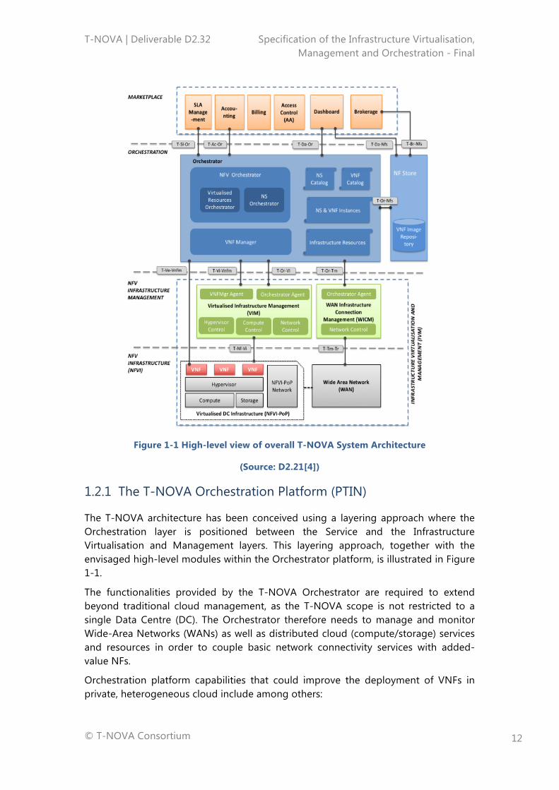
The overall T-NOVA system architecture is shown in Figure 1-1 which includes two platforms specified in the present deliverable: the T-NOVA Orchestration and the T-NOVA IVM platforms.
T-NOVA | Deliverable D2.32 Specification of the Infrastructure Virtualisation, Management and Orchestration - Final
© T-NOVA Consortium
12
Figure 1-1 High-level view of overall T-NOVA System Architecture
(Source: D2.21[4])
1.2.1 The T-NOVA Orchestration Platform (PTIN)
The T-NOVA architecture has been conceived using a layering approach where the Orchestration layer is positioned between the Service and the Infrastructure Virtualisation and Management layers. This layering approach, together with the envisaged high-level modules within the Orchestrator platform, is illustrated in Figure 1-1.
The functionalities provided by the T-NOVA Orchestrator are required to extend beyond traditional cloud management, as the T-NOVA scope is not restricted to a single Data Centre (DC). The Orchestrator therefore needs to manage and monitor Wide-Area Networks (WANs) as well as distributed cloud (compute/storage) services and resources in order to couple basic network connectivity services with added-value NFs.
Orchestration platform capabilities that could improve the deployment of VNFs in private, heterogeneous cloud include among others:
T-NOVA | Deliverable D2.32 Specification of the Infrastructure Virtualisation, Management and Orchestration - Final
© T-NOVA Consortium
13
• Application assignment to hardware platforms capable of improving its performance though specific features, such as special purpose instructions or accelerators i.e. allocation of a Single Root I/O Virtualisation (SR-IOV) virtual function to VMs running VNFs that can benefit from the capability;
• Exploitation of Enhanced platform awareness (EPA) information, which is extracted from each NFVI, in order to optimise the resource mapping algorithms.
• Support of live-migration (wherever applicable, taking into account the service provided by each VNF).
The Orchestrator’s requirements together with its detailed conception and description in terms of Functional Elements (Fes) constitute the outputs of Task T2.3 which are described in Section 3.
1.2.2 The T-NOVA IVM Platform
The IVM layer in the T-NOVA system is responsible for providing the execution environment for VNFs. The IVM is comprised of a Network Function Virtualised Infrastructure (NFVI), Virtualised Infrastructure Manager (VIM) and a WAN Infrastructure Connection Management (WICM). The IVM provides full abstraction of the NFVI resources to VNFs. The IVM achieves this by supporting separation of the software that defines the network function (the VNF) from the hardware and generic software that constitute the NFVI. Control and management of the NFVI is carried out by the VIM in unison with the Orchestrator. While the IVM provides orchestration of the virtualised resources in the form of compute, storage and networking, responsibility for the orchestration of the VNFs is solely a function of the Orchestration layer given its system wide view of the T-NOVA system and centralised coordination role in the system.
A major challenge for vendors developing NFV-based solutions is achieving near-native performance (i.e., similar to non-virtualised) in a virtualised environment. One critical aspect is minimising the inherent overhead associated with virtualisation, and there has been significant progress thanks to a number of key innovations. An example is hardware-assisted virtualisation in CPUs, such as Intel’s Xeon microprocessors with Intel VT-x, which reduces VM context switching time, among other things.
Another challenge is ensuring the orchestration layer fully exploits the capabilities of the servers it manages. Typical orchestration layer products can identify infrastructural features (e.g., CPU type, Random Access Memory (RAM) size and host operating system); however, some orchestrators are unaware of attached devices, like acceleration cards or network interface cards (NICs) with advanced capabilities. In such cases, they are unable to proactively load an application onto a platform capable of accelerating its performance, as in assigning an IP security (IPsec) VPN appliance to a server with cryptographic algorithm acceleration capabilities. Other features of the platform may be of interest, i.e. the model and version of CPU, the number of cores, and other specific features.
T-NOVA | Deliverable D2.32 Specification of the Infrastructure Virtualisation, Management and Orchestration - Final
© T-NOVA Consortium
14
The lack of platform and infrastructural awareness is a major drawback since many virtual appliances have intense I/O requirements and could benefit from access to high-performance instructions, accelerators and Network Interface Cards (NICs) for workloads such as compression, cryptography and transcoding. This is a key focus in WP3 (Task 3.2) and WP4 (Task 4.1). Undoubtedly, making the orchestration layer aware of the innate capabilities of the devices attached to server platforms can help maximise network performance.
The outputs of Task 2.4 with respect to the overall integrated architecture of the IVM layer are presented in Section 3.
T-NOVA | Deliverable D2.32 Specification of the Infrastructure Virtualisation, Management and Orchestration - Final
© T-NOVA Consortium
15
2. THE T-NOVA ORCHESTRATION LAYER
This section describes the Orchestration layer, starting with an overview of its main characteristics, challenges and framework (subsection 3.1); followed by a description of requirements associated with its FEs (subsection 3.2), and finally a description of its functional architecture (subsection 3.3).
2.1. Orchestration Layer Overview
NFV is an emerging concept, which refers to the migration of certain network functionalities, traditionally performed by dedicated hardware elements, to virtualised IT infrastructures where they are deployed as software components. NFV leverages commodity servers and storage to enable rapid deployment, reconfiguration and elastic scaling of network functionalities.
Decoupling the network functions software from the hardware creates a new set of entities, namely:
• Virtual Network Functions (VNFs): software-based network functions deployed over virtualised infrastructure;
• Network Functions Virtualized Infrastructure (NFVI): virtualised hardware that supports the deployment of network functions;
• Network Service (NS): chain of VNFs and/or Physical Network Functions (PNFs) interconnected through virtual network links (VLs).
Since VNFs, NFVIs, NSs and the relationships between them did not exist before the NFV paradigm, handling them requires a new and different set of management orchestration functions.
VNFs require more agile management procedures when compared with legacy PNFs deployed over dedicated appliances. Besides the traditional management procedures already in place for PNFs, in charge of BSSs/OSSs, such as customer management, accounting management and SLA management, VNFs require new management procedures, e.g. to automatically create, to update and/or to terminate VNFs and NSs. Furthermore, the automatic deployment and instantiation procedures associated with a specific VNF need to be in place as well as the monitoring and automatic scaling procedures during the service runtime phase.
Another challenge brought about by the NFV paradigm is the management of the virtualised infrastructure. In fact, one of the main advantages of virtualising network functions is to enable the automatic adjustment of NFVI resources according to the network function demands. To achieve this, the VNF specific requirements, according to the contracted SLA, have to be mapped to the required virtualised infrastructure assets (compute – e.g. virtual and physical machines, storage and networking – e.g. networks, subnets, ports and addresses). The mapping procedures should also consider the network topology, connectivity and network QoS constraints, as well as function characteristics (e.g. some functions may require low delay, low loss or high
T-NOVA | Deliverable D2.32 Specification of the Infrastructure Virtualisation, Management and Orchestration - Final
© T-NOVA Consortium
16
bandwidth). Since virtualised resources can be centralised in a single NFVI-PoP or distributed across several NFVI-PoPs, the management and orchestration entities will also have to decide what is the most appropriated NFVI-PoP or NFVI-PoPs to deploy the function.
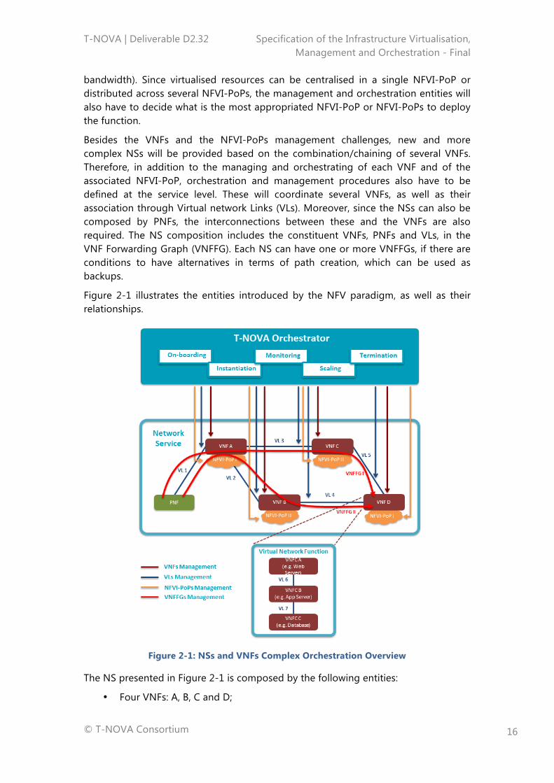
Besides the VNFs and the NFVI-PoPs management challenges, new and more complex NSs will be provided based on the combination/chaining of several VNFs. Therefore, in addition to the managing and orchestrating of each VNF and of the associated NFVI-PoP, orchestration and management procedures also have to be defined at the service level. These will coordinate several VNFs, as well as their association through Virtual network Links (VLs). Moreover, since the NSs can also be composed by PNFs, the interconnections between these and the VNFs are also required. The NS composition includes the constituent VNFs, PNFs and VLs, in the VNF Forwarding Graph (VNFFG). Each NS can have one or more VNFFGs, if there are conditions to have alternatives in terms of path creation, which can be used as backups.
Figure 2-1 illustrates the entities introduced by the NFV paradigm, as well as their relationships.
Figure 2-1: NSs and VNFs Complex Orchestration Overview
The NS presented in Figure 2-1 is composed by the following entities:
• Four VNFs: A, B, C and D;
T-NOVA | Deliverable D2.32 Specification of the Infrastructure Virtualisation, Management and Orchestration - Final
© T-NOVA Consortium
17
• One PNF;
• Five VLs: 1 (interconnecting VNF A and PNF), 2 (interconnecting VNF A and VNF B, 3 (interconnecting VNF A and VNF C), 4 (interconnecting VNF B and VNF D) and 5 (interconnecting VNF C and VNF D).
The VNFs are deployed over two different NVFI-PoPs:
• NFVI-PoP I: supports VNF A and D deployments;
• NFVI-PoP II: supports VNF B and C deployments.
Two VNFFGs are illustrated:
• VNFFG I: delivers the NS through the PNF – VNF A – VNF C – VNF D networking path;
• VNFFG II: delivers the NS through the PNF – VNF A – VNF B – VNF D networking path.
Internally, the VNFs can be composed by one or more software components, also known as Virtual Network Function Components (VNFCs). Each VNFC is typically deployed in a single Virtual Machine (VM), although other deployment procedures can exist. As VNFs, VNFCs can be instantiated in a single NFVI-PoP or distributed across several NFVI-PoPs. The VNFCs interconnections are made through dedicated VLs. Figure 2-1 illustrates the internals of a specific (VNF D). The latter software components, namely web server (VNFC A), application server (VNFC B) and database (VNFC C), interconnected through VLs (VL6 and VL7).
On top of all these entities (e.g. NS, VNF, VNFC, VL, NFVI-PoP, etc.) stands the orchestrator, which has responsibility for managing the complexity associated with the NSs and VNFs lifecycle management (e.g. on-boarding/deployment, instantiation, supervision, scaling, termination), including the internals of the VNFs (not illustrated in the figure).
In summary, the T-NOVA Orchestrator platform is focused on addressing two of the most critical issues in NFV:
1. Automated deployment and configuration of NSs/VNFs;
2. Management and optimisation of networking and IT resources for VNFs accommodation.
To address the complex management processes related with the NSs and VNFs, the Orchestrator is split in two main FEs:
1. NFV Orchestrator (NFVO): manages the virtualised NSs lifecycle procedures, including the networking links that interconnect the VNFs;
2. VNF Manager (VNFM): manages the VNFs lifecycle procedures.
The T-NOVA Orchestrator will also be able to deploy and monitor T-NOVA services by jointly managing WAN resources and cloud (compute/storage) assets (DCs). Indeed, the T-NOVA Orchestrator goes beyond traditional cloud management, since its scope is not restricted to a single DC; it needs to jointly manage WAN and distributed cloud resources in different interconnected DCs in order to couple the basic network connectivity service with added-value NFs.
T-NOVA | Deliverable D2.32 Specification of the Infrastructure Virtualisation, Management and Orchestration - Final
© T-NOVA Consortium
18
Further details regarding these T-NOVA Orchestrator entities and functionalities are provided in the following subsections. The VNF related concepts and architectural components are discussed extensively in Deliverable D2.41 [5].
2.2. Orchestrator Requirements
As already outlined in subsection 2.1, the T-NOVA Orchestrator is composed by two main building blocks: the NFVO and the VNFM.
The NFVO orchestrates the subset of functions that are responsible for the lifecycle management of Network Services (NSs). In addition, it is also responsible for the resource orchestration of the NFVI resources across:
• A single VIM, corresponding to a single NFVI-PoP, and/or
• Multiple VIMs, corresponding to multiple NFVI-PoPs, by using a specialized VIM designated by WICM.
The VNFM is the functional block that is responsible for the lifecycle management of the VNFs.
The deployment and operational behaviour of the Orchestrator is captured in deployment templates, where the most important for this subsection are the Network Service Descriptor (NSD) and the Virtual Network Function Descriptor (VNFD). Other templates are also used, e.g., Virtual Link Descriptor (VLD), and the VNF Forwarding Graph (VNFFGD), which will be further detailed in subsection 2.3.
This subsection details the Orchestrator requirements that have been identified after a research study involving several sources, e.g. use cases defined in D2.1 [6], ETSI ISG NFV requirements [7], ITU-T requirements for NV [8], as well as excerpts of relevant parts of the ETSI ISG MANO architecture and associated FEs [9].
The list of requirements for each FE may be found in Annex A, where 27 requirements have been identified for the NFVO and 6 requirements for the VNFM. However, it should be noted that none of these requirements imposes any specific solution at the implementation level, which will be performed in WP3/4.
Taking into account that the list of requirements is quite extensive, the entire set of requirements has been classified and divided into types as indicated in the remaining part of the current subsection.
2.2.1. NFVO Requirements Types
Network Services under the responsibility of the NFVO, are composed by VNFs and, as such, are defined by their functional and behavioural specification. In this context, the NFVO coordinates the lifecycle of VNFs that jointly realise a NS. This coordination includes managing the associations between the different VNFs that make-up part of the NS, and when applicable between VNFs and PNFs, the network topology of the NS, and the VNFFGs associated with the NS.
The operation of NSs defines the behaviour of the higher Orchestration layer, which is characterised by performance, dependability, and security specifications. The end-
T-NOVA | Deliverable D2.32 Specification of the Infrastructure Virtualisation, Management and Orchestration - Final
© T-NOVA Consortium
19
to-end network service behaviour is the result of combining individual network function behaviours as well as the behaviours of the composition mechanisms associated with the underlying network infrastructure layer, i.e. the IVM layer.
In terms of deployment and operational behaviour, the requirements of each NS are carried in a deployment template, the NSD, and stored during the NS on-boarding process in the NS catalogue, for future selection once the instantiation of the service takes place. The NSD fully describes the attributes and requirements necessary to implement a NS, including the service topology, i.e. constituent VNFs and the relationships between them, VLs, VNFFGs, as well as NS characteristics, e.g. in terms of SLAs and any other information necessary for the NS on-boarding and lifecycle management of its instances.
As the NS is the main responsibility of the NFVO, the NS lifecycle constitutes the most relevant technical area regarding the NFVO classification in terms of requirements.
As indicated below, the other requirement types are related with the VNF lifecycle management with respect to the actions and procedures taken by the NFVO, which also includes the second FE that constitutes part of the Orchestrator, together with the NFVO: the VNFM. The actions and procedures associated with the VNFM’s behaviour, and in particular those related to the VNF lifecycle, will be further discussed in subsection 2.2.2.
Regarding the remaining requirement types, it should be noted that there is one type related to the NFVO, which handles the management of the resources located in the VIM and in the WICM; another one related with the policy management; and another one, specific to the T-NOVA system, which is concerned with the most relevant interactions with the Marketplace, the layer immediately above the Orchestration layer.
Finally, there are still two further types that relate to NS lifecycle operations: connectivity handling and the monitoring process. A decision was taken to create separate groups for these two (sub)types in order to emphasize the importance they play in the overall operation of the Orchestrator.
2.2.1.1. NS Lifecycle
A Service Provider (SP) may choose one or more VNFs to compose a new NS, by parameterising those VNFs, selecting a SLA, etc. within the context of the T-NOVA system. The NFVO is then notified of the composition of this new NS, by the reception of a request that includes a NSD, which is validated in terms of description.
In a similar process, when a Customer subscribes to a NS, the Marketplace notifies the NFVO, which instantiates the NS according to its NSD description, agreed SLA and the current status of the overall infrastructure usage metrics. Upon a successful instantiation, the Orchestrator notifies the Marketplace, thus triggering the accounting process of the subscribed NS as well as of the customer.
T-NOVA | Deliverable D2.32 Specification of the Infrastructure Virtualisation, Management and Orchestration - Final
© T-NOVA Consortium
20
After these steps the NFVO becomes responsible for NS lifecycle management, where lifecycle management refers to a set of functions required to manage the instantiation, maintenance and termination of a NS.
2.2.1.2. VNF Lifecycle
The NFVO performs its capabilities by using the VNFM operation in what concerns the handling of the VNF lifecycle. Although the VNFM is the FE in charge of the management of the VNF lifecycle, as described in subsection 2.2.3, some operations require the intervention of the NFVO.
The requirement type specified in the current subsection refers precisely to those parts of the VNF lifecycle management that are performed by the NFVO.
In this context, Function Providers (FPs) publicise their VNFs in the Network Function Store (NF Store). This implies the use of a VNFD describing the infrastructure (computation, storage, network infrastructure and connection) needed for the VNF to be instantiated later on by a request sent to the Orchestrator.
After a validation of the VNFD, the NFVO publicises the VNF to the Marketplace as being ready to be part of a NS. Associated with the VNFD, there may be potentially a VM image that will make part of the deployment of such VNF.
As the FP provides newer versions this process is repeated. If and when the FP wishes to withdraw the VNF, the reverse process is executed taking into consideration the current status of NS exploiting the under deletion VNF.
2.2.1.3. Resource Handling
The NFVO is the Orchestrator FE that performs the resource handling of the subset of Orchestrator functions that are responsible for global resource management governance.
In terms of scope, the following domains and associated IT virtualised resources are managed by the NFVO: Compute, i.e. virtual processing CPUs and virtual memory; Storage, i.e. virtual storage; and Network, i.e. virtual links intra/interconnecting VNFs within the Data Centre Network (DCN). In T-NOVA, the NFVO also manages the resources of the WICM network domain.
The governance described above is performed by managing the between the VNF instances and the NFVI resources allocated to those VNF instances and by using the Infra Resources catalogue as well as information received from the VIM and from the WICM.
According to the characteristics of each service (agreed SLA) and the current usage of the infrastructure (computation, storage infrastructure and connectivity), there is an optimal allocation for the required infrastructure.
This optimal infrastructure allocation will be the responsibility of an allocation algorithm (or a set of algorithms) that will be defined, in WP3.
T-NOVA | Deliverable D2.32 Specification of the Infrastructure Virtualisation, Management and Orchestration - Final
© T-NOVA Consortium
21
2.2.1.4. Monitoring Process
One of the key aspects of the T-NOVA project is not only the ability to optimally allocate infrastructures for a NS, but also to react, in real time, to the current performance of a subscribed NS, so that the agreed SLA is maintained. To accomplish these two aspects, it is crucial that a meaningful set of infrastructure (computational, storage, infrastructure and connectivity) usage metrics be collected.
NS metrics must be defined together with the SLA(s) to be provided with every NS instantiation.
It is expected that the data to be collected will be significant with a high frequency of change, so adequate strategies will have to be designed to support collecting large volumes of data.
As such, during the NS lifecycle, the NFVO may monitor the overall operation of a NS with information provided by the VIM and/or by the WICM, if such requirements were captured in the NS deployment template.
Such data may be used to derive usage information for NFVI resources being consumed by VNF instances or groups of VNF instances. For instance, the process may involve collecting measurements about the number of NFVI resources consumed by NFVI interfaces, and then correlating NFVI usage records to VNF instances.
Beyond the infrastructure usage metrics sets of NS usage metrics, need to be defined upon service composition, in order to allow tracking of the agreed SLA and to determine if it is being maintained or not.
These metrics are more service oriented than infrastructure oriented, and are built on top of infrastructure usage metrics. For instance, a metric such as “the current number of simultaneous sessions” is something that the infrastructure cannot measure, but the “current maximum network latency” is something available at the infrastructure level, which might make sense at the service level as well. The choice between which metrics to track is made by the Marketplace, at service composition time.
The collection of these measurement metrics may be reported to external entities, e.g. the Customer, the SP or the FP, via the Marketplace, if such requirements were captured in the NS deployment template.
In addition, this information may be compared with additional information included in the on-boarded NS and VNF deployment templates, as well as with policies applicable to the NS that can be used to trigger automatic operational management of the NS instance, e.g. automatic scaling of VNF instances that are part of the NS.
2.2.1.5. Connectivity Handling
The NFVO has an abstracted view of the network topology and interfaces to the underlying VIMs and WICMs in order to handle connectivity services by performing the management of the NS instances, e.g., create, update, query, delete VNFFGs.
Connectivity management must be handled over the same domains as those indicated for resource handling.
T-NOVA | Deliverable D2.32 Specification of the Infrastructure Virtualisation, Management and Orchestration - Final
© T-NOVA Consortium
22
2.2.1.6. Policy Management
Policies are defined by conditions and corresponding actions/procedures, e.g. a scaling policy may state execution of specific actions/procedures if the required conditions occur during runtime. Different actions/procedures defined by the policy can be mutually exclusive, which implies a process of selection of a particular action/procedure (or set of actions/procedures) to be executed either automatically or manually.
In the context of T-NOVA, once declared, a policy may be bound to one or more NS instances, VNF instances, and NFVI resources. Policy management always implies some degree of evaluation for the NS instances and VNF instances, e.g., in term of policies related with affinity/anti-affinity, lifecycle operations, geography, regulatory rules, NS topology, etc.
In addition, policy management also refers to the management of rules governing the behaviour of Orchestrator functions, e.g., management of NS or VNF scaling operations, access control, resource management, fault management, etc.
Associated with the policy management terminology is the concept of policy enforcement, i.e. polices are defined by certain entities and are then enforced in other entities, which may in their turn enforce them in additional entities.
In the T-NOVA context, policies may be defined by external entities, e.g. the Customer, the SP or the FP, and are then enforced into the NFVO, via the Marketplace. In its turn, the NFVO may enforce them into the VNFM.
Policy enforcement may be static or on-demand.
2.2.1.7. Marketplace-specific Interactions
The Marketplace is the T-NOVA layer that interfaces with external entities, e.g., Customers, SPs and FPs. In the T-NOVA global architecture, it interacts with the Orchestration layer through an interface whose requirements are defined in subsection 2.4.
The deployment and behaviour of the Marketplace imposes requirements that the Orchestration must fulfil in order to offer those external entities an entire set of functionalities, which are defined in D2.41 [5].
The request made by the Marketplace for those requirements as well as the correspondent responses from the Orchestrator are, most of the time, implicit in the current description of the Orchestrator requirements.
However, for some of those requirements that are based within D2.1 [6], e.g. publishing the outcome of the NS instantiation, publishing NS metrics, or reporting usage metrics, it was decided to create a separate group in order to highlight their processing mechanisms.
For instance, the various kinds of metrics described above may be used by business-oriented processes residing in the Marketplace, namely to start and stop tracking of the usage a NS for billing purposes.
T-NOVA | Deliverable D2.32 Specification of the Infrastructure Virtualisation, Management and Orchestration - Final
© T-NOVA Consortium
23
2.2.2. VNFM Requirements Types
The deployment and operational behaviour requirements of each VNF is captured in a deployment template, the VNFD, and stored during the VNF on-boarding process in the VNF catalogue as part of a VNF Package, for future use. The deployment template describes the attributes and requirements necessary to realise such the VNF and captures, in an abstracted manner, the requirements to manage its lifecycle.
The VNFM performs the lifecycle management of a VNF based on the requirements included in this template. As such, the VNF lifecycle constitutes the most relevant type in the VNFM classification of requirements in relation to the procedures taken in this global process.
As also decided for the NFVO, there is still a further type that constitutes, in fact, an area of operation that belongs to the VNF lifecycle: the monitoring process. Once again, the reason behind the creation of a separate group for this (sub)type is related to emphasising the importance of its rule in the Orchestrator’s operation.
2.2.2.1. VNF Lifecycle
The VNFM is responsible for the VNF lifecycle management, where lifecycle management refers to a set of functions required to manage the instantiation, maintenance, scaling and termination of a VNF. The VNF lifecycle is defined in deliverable D2.42 [10].
2.2.2.2. Monitoring Process
During the lifecycle of a VNF, the VNF Management functions may monitor Key Parameter Indicator (KPIs) of a VNF, if such KPIs were captured in the deployment template. The management functions may use this information for scaling operations. Scaling may include changing the configuration of the virtualised resources (scale down, e.g., add CPU, or scale up, e.g., remove CPU), adding new virtualised resources (scale out, e.g., add a new VM), shutting down and removing VM instances (scale in), or releasing some virtualised resources (scale down).
So, every VNF will usually provide its own usage metrics to the VNFM, which will be, in general, specific to the function the VNF provides, although they might be based on the infrastructure on top of which the VNF has been deployed.
The treatment of the information collected during the VNF monitoring process is very similar to the one described for the NS process and may result in reports being sent external entities, via the Marketplace, and/or to trigger automatic operational management of the VNF instance, e.g. automatic scaling.
2.3. Functional Orchestrator Architecture
This subsection describes the Orchestrator reference architecture, including its functional entities as well as external interfaces.
T-NOVA | Deliverable D2.32 Specification of the Infrastructure Virtualisation, Management and Orchestration - Final
© T-NOVA Consortium
24
2.3.1. Reference Architecture
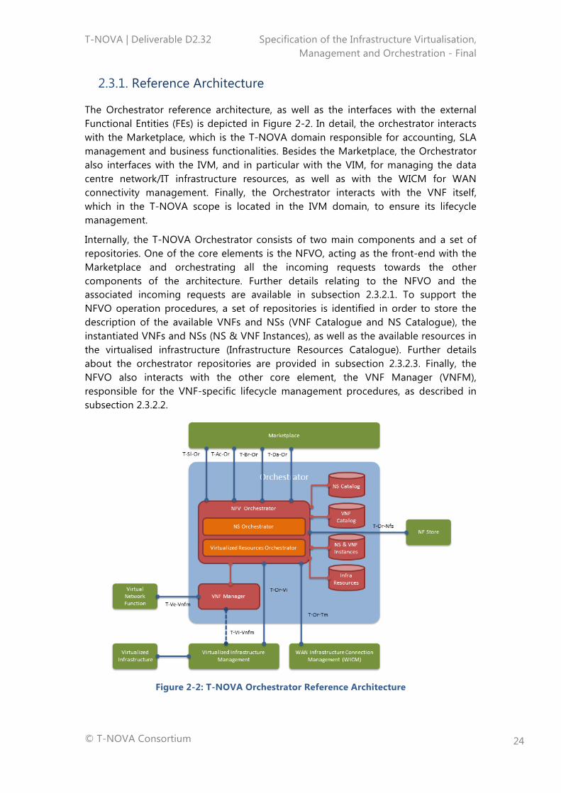
The Orchestrator reference architecture, as well as the interfaces with the external Functional Entities (FEs) is depicted in Figure 2-2. In detail, the orchestrator interacts with the Marketplace, which is the T-NOVA domain responsible for accounting, SLA management and business functionalities. Besides the Marketplace, the Orchestrator also interfaces with the IVM, and in particular with the VIM, for managing the data centre network/IT infrastructure resources, as well as with the WICM for WAN connectivity management. Finally, the Orchestrator interacts with the VNF itself, which in the T-NOVA scope is located in the IVM domain, to ensure its lifecycle management.
Internally, the T-NOVA Orchestrator consists of two main components and a set of repositories. One of the core elements is the NFVO, acting as the front-end with the Marketplace and orchestrating all the incoming requests towards the other components of the architecture. Further details relating to the NFVO and the associated incoming requests are available in subsection 2.3.2.1. To support the NFVO operation procedures, a set of repositories is identified in order to store the description of the available VNFs and NSs (VNF Catalogue and NS Catalogue), the instantiated VNFs and NSs (NS & VNF Instances), as well as the available resources in the virtualised infrastructure (Infrastructure Resources Catalogue). Further details about the orchestrator repositories are provided in subsection 2.3.2.3. Finally, the NFVO also interacts with the other core element, the VNF Manager (VNFM), responsible for the VNF-specific lifecycle management procedures, as described in subsection 2.3.2.2.
Figure 2-2: T-NOVA Orchestrator Reference Architecture
T-NOVA | Deliverable D2.32 Specification of the Infrastructure Virtualisation, Management and Orchestration - Final
© T-NOVA Consortium
25
2.3.2. Functional Entities
This subsection describes the functional entities of the Orchestrator architecture.
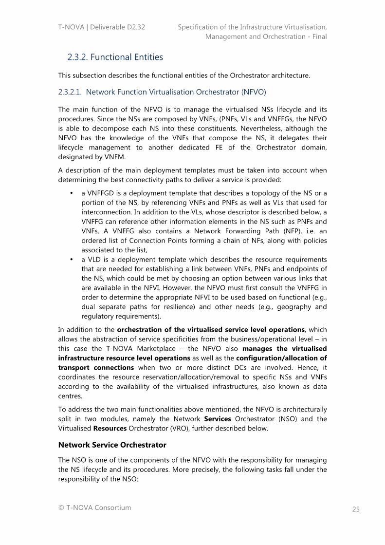
2.3.2.1. Network Function Virtualisation Orchestrator (NFVO)
The main function of the NFVO is to manage the virtualised NSs lifecycle and its procedures. Since the NSs are composed by VNFs, (PNFs, VLs and VNFFGs, the NFVO is able to decompose each NS into these constituents. Nevertheless, although the NFVO has the knowledge of the VNFs that compose the NS, it delegates their lifecycle management to another dedicated FE of the Orchestrator domain, designated by VNFM.
A description of the main deployment templates must be taken into account when determining the best connectivity paths to deliver a service is provided:
• a VNFFGD is a deployment template that describes a topology of the NS or a portion of the NS, by referencing VNFs and PNFs as well as VLs that used for interconnection. In addition to the VLs, whose descriptor is described below, a VNFFG can reference other information elements in the NS such as PNFs and VNFs. A VNFFG also contains a Network Forwarding Path (NFP), i.e. an ordered list of Connection Points forming a chain of NFs, along with policies associated to the list,
• a VLD is a deployment template which describes the resource requirements that are needed for establishing a link between VNFs, PNFs and endpoints of the NS, which could be met by choosing an option between various links that are available in the NFVI. However, the NFVO must first consult the VNFFG in order to determine the appropriate NFVI to be used based on functional (e.g., dual separate paths for resilience) and other needs (e.g., geography and regulatory requirements).
In addition to the orchestration of the virtualised service level operations, which allows the abstraction of service specificities from the business/operational level – in this case the T-NOVA Marketplace – the NFVO also manages the virtualised infrastructure resource level operations as well as the configuration/allocation of transport connections when two or more distinct DCs are involved. Hence, it coordinates the resource reservation/allocation/removal to specific NSs and VNFs according to the availability of the virtualised infrastructures, also known as data centres.
To address the two main functionalities above mentioned, the NFVO is architecturally split in two modules, namely the Network Services Orchestrator (NSO) and the Virtualised Resources Orchestrator (VRO), further described below.
Network Service Orchestrator
The NSO is one of the components of the NFVO with the responsibility for managing the NS lifecycle and its procedures. More precisely, the following tasks fall under the responsibility of the NSO:

T-NOVA | Deliverable D2.32 Specification of the Infrastructure Virtualisation, Management and Orchestration - Final
© T-NOVA Consortium
26
• NSs and VNFs on-boarding: management of Network Services deployment templates, also known as NS Descriptors and VNF Packages, as well as of the NSs instances topology (e.g., create, update, query, delete VNF Forwarding Graphs). On-boarding of a NS includes the registration in the NS catalogue therefore ensuring that all the templates (NSDs) are stored, see NS on-boarding procedure detailed in subsection 5.2.1;
• NS instantiation: trigger instantiation of NS and VNF instances, according to triggers and actions captured in the on-boarded NS and VNF deployment templates. In addition, management of the instantiation of VNFs, in coordination with VNFMs as well as validation of NFVI resource requests from VNFMs, as those may impact NSs, e.g. scaling process, see NS instantiation procedure detailed in subsection 5.2.2;
• NS update: support NS configuration changes of various complexity such as changing inter-VNF connectivity or the constituent VNFs;
• NS supervision: monitoring and measurement of the NS performance and correlation of the acquired metrics for each service instance. Data is obtained from the IVM layer (performance metrics related with the virtual network links interconnecting the network functions) and from the VNFM (aggregated performance metrics related with the VNF, see NS supervision procedure detailed in subsection 5.2.3;
• NS scaling: increase or decrease of the NS capacity according to per-instance and per-service auto-scaling policies. The NS scaling can imply either increasing/decreasing of a specific VNF capacity, create/terminate new/old VNF instances and/or increase/decrease the number of connectivity links between the network functions;
• NS termination: release of a specific NS instance by removing the associated VNFs and associated connectivity links, as well as the virtualised infrastructure resources, (see NS termination procedure detailed in subsection 4.2.5).
In addition to these lifecycle related procedures, the NSO also performs policy management and evaluation for the NS instances and VNF instances, e.g., policies related with scaling.
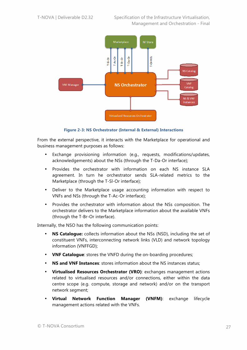
Figure 2-3 provides an illustration about the NSO interactions within the T-NOVA Orchestrator and with the remaining T-NOVA external entities:
T-NOVA | Deliverable D2.32 Specification of the Infrastructure Virtualisation, Management and Orchestration - Final
© T-NOVA Consortium
27
Figure 2-3: NS Orchestrator (Internal & External) Interactions
From the external perspective, it interacts with the Marketplace for operational and business management purposes as follows:
• Exchange provisioning information (e.g., requests, modifications/updates, acknowledgements) about the NSs (through the T-Da-Or interface);
• Provides the orchestrator with information on each NS instance SLA agreement. In turn he orchestrator sends SLA-related metrics to the Marketplace (through the T-Sl-Or interface);
• Deliver to the Marketplace usage accounting information with respect to VNFs and NSs (through the T-Ac-Or interface);
• Provides the orchestrator with information about the NSs composition. The orchestrator delivers to the Marketplace information about the available VNFs (through the T-Br-Or interface).
Internally, the NSO has the following communication points:
• NS Catalogue: collects information about the NSs (NSD), including the set of constituent VNFs, interconnecting network links (VLD) and network topology information (VNFFGD);
• VNF Catalogue: stores the VNFD during the on-boarding procedures;
• NS and VNF Instances: stores information about the NS instances status;
• Virtualised Resources Orchestrator (VRO): exchanges management actions related to virtualised resources and/or connections, either within the data centre scope (e.g. compute, storage and network) and/or on the transport network segment;
• Virtual Network Function Manager (VNFM): exchange lifecycle management actions related with the VNFs.
T-NOVA | Deliverable D2.32 Specification of the Infrastructure Virtualisation, Management and Orchestration - Final
© T-NOVA Consortium
28
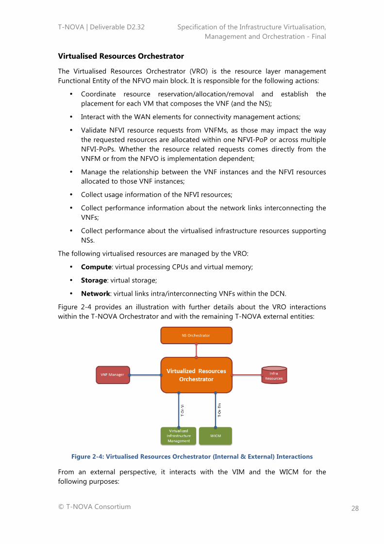
Virtualised Resources Orchestrator
The Virtualised Resources Orchestrator (VRO) is the resource layer management Functional Entity of the NFVO main block. It is responsible for the following actions:
• Coordinate resource reservation/allocation/removal and establish the placement for each VM that composes the VNF (and the NS);
• Interact with the WAN elements for connectivity management actions;
• Validate NFVI resource requests from VNFMs, as those may impact the way the requested resources are allocated within one NFVI-PoP or across multiple NFVI-PoPs. Whether the resource related requests comes directly from the VNFM or from the NFVO is implementation dependent;
• Manage the relationship between the VNF instances and the NFVI resources allocated to those VNF instances;
• Collect usage information of the NFVI resources;
• Collect performance information about the network links interconnecting the VNFs;
• Collect performance about the virtualised infrastructure resources supporting NSs.
The following virtualised resources are managed by the VRO:
• Compute: virtual processing CPUs and virtual memory;
• Storage: virtual storage;
• Network: virtual links intra/interconnecting VNFs within the DCN.
Figure 2-4 provides an illustration with further details about the VRO interactions within the T-NOVA Orchestrator and with the remaining T-NOVA external entities:
Figure 2-4: Virtualised Resources Orchestrator (Internal & External) Interactions
From an external perspective, it interacts with the VIM and the WICM for the following purposes:
T-NOVA | Deliverable D2.32 Specification of the Infrastructure Virtualisation, Management and Orchestration - Final
© T-NOVA Consortium
29
• Virtualised Infrastructure Manager: to enforce resource reservation/allocations/removal and to collect monitoring information about the virtual links interconnections of the VNFs, through the T-Or-Vi interface;
• Transport Network Manager: enforces resource/connectivity decisions allocations/removals and to collect monitoring information about the transport network elements, through the T-Or-Tm interface.
Internally, the VRO interacts with the following blocks:
• Network Services Orchestrator: exchanges resource reservation/allocation/removal management actions related with a specific NS, for all the constituent VNFs;
• Infrastructure Resources catalogue: queries and stores information about the virtualised and non-virtualised infrastructure resources;
• Virtual Network Function Manager: exchanges resource reservation/allocation/removal management actions, in the case the resource management is handled by the VNFM.
2.3.2.2. Virtual Network Function Manager (VNFM)
The VNFM is responsible for the lifecycle management of the VNF. Each VNF instance is assumed to have an associated VNFM. A VNFM may be assigned the management of a single VNF instance, or the management of multiple VNF instances of the same type or of different types. The Orchestrator uses the VNFD to create instances of the VNF it represents, and to manage the lifecycle of those instances. A VNFD has a one-to-one correspondence with a VNF Package, and it fully describes the attributes and requirements necessary to realize such a VNF. NFVI resources are assigned to a VNF based on the requirements captured in the VNFD (containing resource allocation criteria, among others), but also taking into consideration specific requirements accompanying the request for instantiation.
The following management procedures are within the scope of the VNFM:
• Instantiate: create a VNF on the virtualised infrastructure using the VNF on-boarding descriptor, as well as the VNF feasibility checking procedure, see VNF instantiation procedure detailed in subsection 4.1.2;
• Configure: configure the instantiated VNF with the required information to start the VNF. The request may already include some customer-specific attributes/parameters;
• Monitor: collect and correlate monitoring information for each instance of the VNF. The collected information is obtained from the IVM layer (virtualised infrastructure performance information) and from the VNF (service specific performance information), see VNF monitoring procedure detailed in section 4.1.3;
• Scale: increase or decrease the VNF capacity by adding/removing VMs (out/in horizontal scaling) see VNF scale-out procedure detailed in subsection 4.1.4;
• Update: modify configuration parameters;
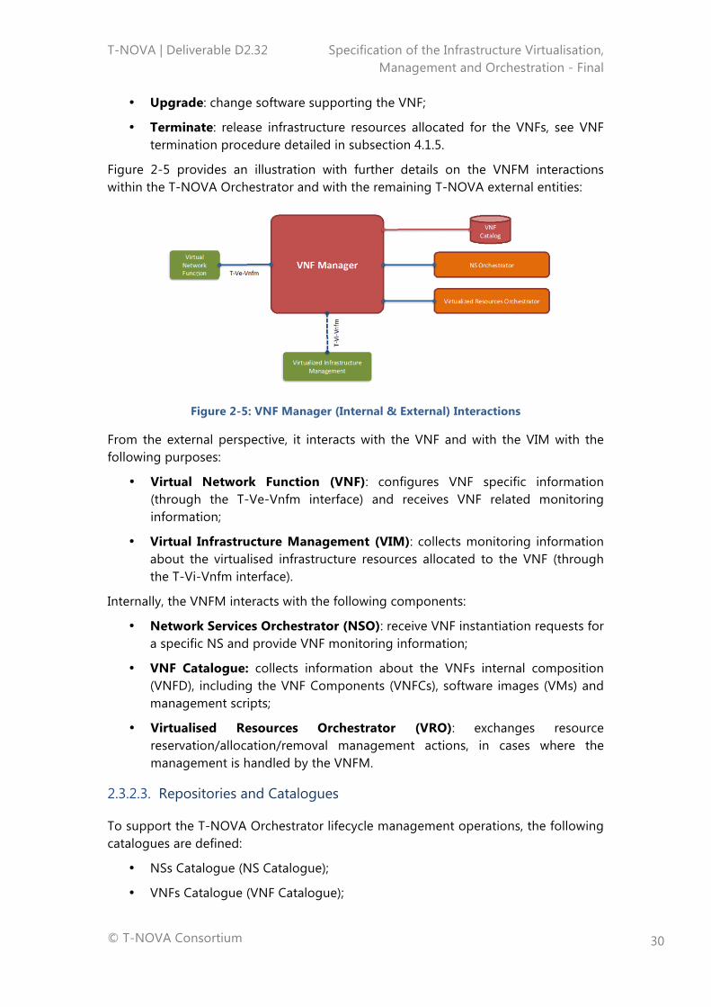
T-NOVA | Deliverable D2.32 Specification of the Infrastructure Virtualisation, Management and Orchestration - Final
© T-NOVA Consortium
30
• Upgrade: change software supporting the VNF;
• Terminate: release infrastructure resources allocated for the VNFs, see VNF termination procedure detailed in subsection 4.1.5.
Figure 2-5 provides an illustration with further details on the VNFM interactions within the T-NOVA Orchestrator and with the remaining T-NOVA external entities:
Figure 2-5: VNF Manager (Internal & External) Interactions
From the external perspective, it interacts with the VNF and with the VIM with the following purposes:
• Virtual Network Function (VNF): configures VNF specific information (through the T-Ve-Vnfm interface) and receives VNF related monitoring information;
• Virtual Infrastructure Management (VIM): collects monitoring information about the virtualised infrastructure resources allocated to the VNF (through the T-Vi-Vnfm interface).
Internally, the VNFM interacts with the following components:
• Network Services Orchestrator (NSO): receive VNF instantiation requests for a specific NS and provide VNF monitoring information;
• VNF Catalogue: collects information about the VNFs internal composition (VNFD), including the VNF Components (VNFCs), software images (VMs) and management scripts;
• Virtualised Resources Orchestrator (VRO): exchanges resource reservation/allocation/removal management actions, in cases where the management is handled by the VNFM.
2.3.2.3. Repositories and Catalogues
To support the T-NOVA Orchestrator lifecycle management operations, the following catalogues are defined:
• NSs Catalogue (NS Catalogue);
• VNFs Catalogue (VNF Catalogue);

T-NOVA | Deliverable D2.32 Specification of the Infrastructure Virtualisation, Management and Orchestration - Final
© T-NOVA Consortium
31
• NSs and VNFs Instances Repository;
• Infrastructure Resources Repository.
NS Catalogue
Represents the repository of all the on-boarded NSs in order to support the NS lifecycle management:
• NS Descriptor (NSD): contains the service description template, including SLAs, deployment flavours, references to the virtual links (VLDs) and the constituent VNFs (VNFFG);
• Virtual Link Descriptor (VLD): contains the description of the virtual network links that compose the service (interconnecting the VNFs);
• VNF Forwarding Graph Descriptor (VNFFGD): contains the NS constituent VNFs, as well as their deployment in terms of network connectivity.
VNF Catalogue
Represents the repository of all the on-boarded VNFs in order to support its lifecycle management:
• VNF Descriptor (VNFD): contains the VNF description template, including its internal decomposition in VNFCs, deployment flavours and references to the VLDs;
• Software images of the VMs located in the IVM layer.
NS and VNF Instances
Represents the repository of all the instantiated NSs and VNFs, which can be created/updated/released during the lifecycle management operations.
Infrastructure Resources
Represents the repository of available, reserved and allocated NFVI-PoP resources, also including the ones related to the WAN segment.
2.3.3. External Interfaces
In this section the external interfaces of the Orchestrator are described. However it is important within the perspective of the T-NOVA architecture to understand the context in which the term interface is used as is its relationship to reference points a common architectural locus used within the networking domain
In network terms a reference point is an abstract point in a model of network or protocol. This reference point essentially serves to partition functions or configurations and so assists in the description of a network model as well as serving as a point of interoperability between different parts of the network [11]. In a networking context, an interface may or may not be associated with any given reference point. An interface typically represents a protocol level connection which may or may not be mapped to a reference point.
T-NOVA | Deliverable D2.32 Specification of the Infrastructure Virtualisation, Management and Orchestration - Final
© T-NOVA Consortium
32
This strict delimitation between the definition of reference points and interfaces in the context of NFV and SDN given the hybridisation of networking and IT technologies can be challenging, i.e. in the network domain, this framework is strictly defined, and it is therefore normal practice to retain the use of the term reference point, while in the IT domain, there is a more flexible demarcation between technologies leading to a degree of hybridisation. As a consequence in the IT domain the term interface is used in a more flexible manner to encompass reference points also.
While strictly speaking the separation of the terms should be technically maintained the approach adopted in this deliverable is to utilise a broader and more flexible definition of interfaces and reference points given the expected one-to-one mapping of reference points and interfaces in the context of the proposed T-NOVA architecture. Additionally interfaces in the T-NOVA system may not necessarily be tied specifically to a protocol but rather act as point of information exchange through APIs. Hence within the context of this deliverable interfaces are envisioned to encompass both the architectural characteristics of interfaces and references points given fusion of the IT and networking domains.
Having clarified the use of the term, the description of the Orchestrator’s external interfaces will start to be provided by means of a very short reference on security, which is a common area that affects all the interfaces. It will be followed by an introduction to the interface requirements that are presented in Annex A.2 in a tabular format.
Regarding the common issue, and considering the most generic scenarios in which the roles described in D2.1 [6] are played by distinct entities all the external interfaces being described in this section must support at least a minimum degree of security. The decision on the exact degree of security for each implemented interface will be taken later in the project’s timeline.
2.3.3.1. Interface between the Orchestrator and the Network Function Store
The interface between the Orchestrator and the Network Function Store (NF Store) serves two purposes:
• For the NF Store, to notify the Orchestrator about new, updated and withdrawn VNFs;
• For the Orchestrator, to retrieve from the NF Store and store in the VNF Catalogue the VNFD and VMs images that need to be instantiated to support that VNF.
This “two-phase” interaction between the Orchestrator and the NF Store, instead of just one in which the NF Store could pass the Orchestrator the VNF Descriptor and VM images, allows for the optimisation of resources on both sides of the interface. On the NF Store side this is just a notification to the Orchestrator, and on the Orchestrator’s side, the download of the VM images is only carried out when the VNF is instantiated preventing unnecessary use of resources. Uploading of the VNFD to the VNF catalogue is executed at the start of the VNF on-boarding process.

T-NOVA | Deliverable D2.32 Specification of the Infrastructure Virtualisation, Management and Orchestration - Final
© T-NOVA Consortium
33
2.3.3.2. Interface between the Orchestrator and the Marketplace
The interface between the Orchestrator and the Marketplace serves the following purposes:
• Provide available VNFs: involves SP browsing and selection of VNFs, as well as composition of market services by the Marketplace, followed by a request to the Orchestrator;
• Publish a new network service: related to the request for the storage of information related to a new service by the Marketplace, included in the provision of the NSD (see subsection 2.2). This process is also called NS on-boarding by the Orchestrator FEs;
• Request for a Network Service: after a Customer’s or a SP subscription of a service, a subsequent request from the Marketplace is generated, which includes in the NSD all the VNFs the NS to be deployed needs, as well as all the VMs those VNFs need in the VNFD, the available infrastructure and its current usage;
• Change configuration of a deployed network service upon a request from the Marketplace;
• Provide network service state transitions: notification provided by the Orchestrator to the Marketplace;
• Provide network service monitoring data: notification provided by the Orchestrator to the Marketplace;
• Terminate a provisioned network service: upon a request from the Marketplace when there is an explicit solicitation.
2.3.3.3. Interface between the Orchestrator and the VIM
The interface between the Orchestrator and the VIM serves the following purposes:
• Allocate/release/update resources: upon a request from the Orchestrator to (re)instantiate, update the configuration of, or release a resource (VM or connection within the same DC);
• Reserve/release resources: upon an expected future need from the Orchestrator to instantiate or release a reserved resource (VM or connection in the same DC). This requirement makes sense in scenarios where allocating resources from scratch is complex or too time consuming for the purpose in mind. Reserved resources may have lower prices than effective allocated ones and become faster to allocate when time comes;
• Add/update/delete SW image: whenever a new, update or removal of a VM image is needed in the process of allocating, updating or removing a new VNF/VNFC instance;
• Retrieve infrastructure usage data to NSO: information provided by the VIM to the Orchestrator, NSO FE, so that optimal allocation of NS instances is
T-NOVA | Deliverable D2.32 Specification of the Infrastructure Virtualisation, Management and Orchestration - Final
© T-NOVA Consortium
34
possible and an adequate level of metrics can be reported to the Marketplace, if allowed by information included in the NSD;
• Retrieve infrastructure usage data to VNFM: information provided by the VIM to the Orchestrator, VNFM FE, so that optimal allocation of VNF instances is possible and an adequate level of metrics can be reported, via NSO, to the Marketplace, if allowed by information included in the VNFD;
• Retrieve infrastructure resources metadata to VRO: information provided by the VIM to the Orchestrator, VRO FE, so that optimal allocation of NS instances is possible, according to the characteristics of the supporting infrastructure (e.g., the availability of specialized components, such as Graphical Processing Units (GPUs) or Digital Signal Processors (DSPs), as well as the maximum number of vCPUs or Giga-bytes of RAM, which will influence the allocating algorithm for determining the most appropriate resources);
• Manage VM’s state: information provided by the VIM to the Orchestrator, VNFM FE, so that atomic operations, such as redeployment/withdrawal of an entire VNF, on the allocated VMs are feasible (depending on the implementation approach, these operations can also be done by the IVM layer).
2.3.3.4. Interface between the Orchestrator and the Transport Network Management
The interface between the Orchestrator and the Transport Network Management serves the following purposes:
• Allocate/release/update transport connection: upon a request from the Orchestrator to (re)instantiate, update the configuration of or release a transport connection (between two distinct DCs);
• Reserve/release transport connection: upon an expected future need from the Orchestrator to instantiate or release a transport connection (between two distinct DCs). This requirement makes sense in scenarios where allocating connections from scratch is complex or too time consuming. Reserved connections may have lower prices than effective allocated ones and become faster to allocate when time comes;
• Retrieve transport connection usage data to NSO: information provided by the WICM to the Orchestrator, NSO FE, so that optimal allocation of transport connections between two or more distinct DCs is possible and an adequate level of metrics can be reported, together with VNF an NS level metrics, to the Marketplace;
• Retrieve transport connection metadata: information provided by the WICM to the Orchestrator, VRO FE, such that the optimal allocation of transport connections between two or more distinct DCs is made possible, according to the characteristics of the supporting infrastructure e.g., maximum number of vLinks allowed, maximum bandwidth, etc.;
T-NOVA | Deliverable D2.32 Specification of the Infrastructure Virtualisation, Management and Orchestration - Final
© T-NOVA Consortium
35
• Manage transport connection state: information provided by the WICM to the Orchestrator, NSO FE, so that atomic operations, such as redeployment/withdrawal of an entire VNF within different DCs are feasible (depending on the implementation approach, these operations can also be executed by the IVM layer).
2.3.3.5. Interface between the Orchestrator and the VNF
The interface between the Orchestrator and the VNF serves the following purposes:
• Instantiate/terminate VNF: sent by the VNFM as a request, whenever an instance of a NS of which the VNF is a component is to be launched or removed. Removal of a VNF instance can only be done if there is no NS instance using that VNF.
• Retrieve VNF instance run-time information: sent by the VNFM, so that VNF SLA metrics can be checked and the SLA can be fulfilled;
• Configure a VNF: sent by the VNFM, so that open configuration parameters can be fulfilled later or changed after the VNF instance is already running;
• Manage VNF state: sent by the VNFM, so that the Orchestrator is able to start, stop, suspend already running VNF instances;
• Scale VNF: sent by the VNFM, so that VNF scaling is feasible. All the VNF scaling information is available in the VNFD. Virtualised resources are available through the VRO.
T-NOVA | Deliverable D2.32 Specification of the Infrastructure Virtualisation, Management and Orchestration - Final
© T-NOVA Consortium
36
3. THE T-NOVA IVM LAYER
3.1. INTRODUCTION
T-NOVA’s Infrastructure Virtualisation and Management (IVM) layer provides the requisite hosting and execution environment for VNFs. The IVM incorporates a number of key concepts that influence the associated requirements and architecture for the layer. Firstly the IVM supports separation between control and data planes and network programmability. The T-NOVA architecture leverages SDN for designing, dimensioning and optimising control- and data-plane operations separately, allowing capabilities from the underlying hardware to be exposed independently. Secondly the IVM is based around the use of clusters of SHV computing nodes in cloud computing configurations to support instantiation of software components in the form of VMs for NFV support, offering resource isolation, optimisation and elasticity. This configuration should support automated deployment of VNFs from the T-NOVA marketplace and dynamically expansion/resizing of VMs as required by SLAs. Building on physical IT and network resource domains the IVM provides full abstraction of these resources to VNFs. Finally the IVM must expose the necessary external and internal interfaces to support appropriate integration. The external interfaces provide connectivity with the T-NOVA Orchestration layer in order to execute requests from the Orchestrator and secondly to provide information such as performance metrics relating to the infrastructure and VNFs being hosted in order for the Orchestrator to make effective management decisions. The internal interfaces provide connectivity between the internal domains of the IVM to ensure the requests for the creation, deployment, management and termination of VNF services and their host VMs can be executed appropriately among the constituent infrastructure and control components.
For an architectural perspective the IVM is comprised by NFVI, VIM and WICM functional entities. The NFVI in turn is composed of Compute, Hypervisor and Network Domains. The VIM is comprised of compute, hypervisor and network control and management capabilities, while the WICM works as a single FE. All the FE’s within the IVM implement northbound and southbound interfaces to provide management, control and monitoring of the composite infrastructure, both physical and virtualised. Secondly these interfaces provide the key integration capabilities within the overall T-NOVA system architecture.
The following sections describe the key objectives and characteristics of the IVM and its constituent components, along with their requirements. These requirements where then utilised together with T-NOVA D2.1 [6] and D2.22 [4] to define the architecture of IVM in a manner that addressed these requirements and the overall goals of T-NOVA. The architecture for T-NOVA is presented as an overall integrated architecture together with detailed descriptions of the architecture FEs and interfaces of the constituent domains.
T-NOVA | Deliverable D2.32 Specification of the Infrastructure Virtualisation, Management and Orchestration - Final
© T-NOVA Consortium
37
3.2. OBJECTIVES AND CHARACTERISTICS OF THE T-NOVA IVM LAYER
The T-NOVA IVM is considered to manage a mixture of physical and virtual nodes and will be used to develop, implement and showcase T-NOVA’s services. The IVM will be fully integrated with the T-NOVA Orchestrator to ensure that requirements for the deployment and lifecycle management of T-NOVA VNF services can be carried out in an appropriate and effective manner. The IVM should be sufficiently flexible to support a variety of use cases beyond those explicitly identified in T-NOVA (see D2.1 [6]). As mentioned previously, infrastructure virtualisation plays a key role in achieving this vision in T-NOVA. Virtualisation and management of the virtualised resources extends beyond the compute and storage to include network infrastructure in order to fully exploit the capabilities of the T-NOVA architecture. Virtualisation of the DC network infrastructure allows decoupling of the control functions from the physical devices they control. In this regard T-NOVA is implementing an SDN control plane for designing, dimensioning and optimising the control- and data-plane operations separately, allowing capabilities from the underlying hardware to be exposed independently.
In summary the key objectives for the T-NOVA IVM are as follows:
• Support for the separation of control and data plane and network programmability at least at critical locations within the network such as the network access/borders,
• Utilisation of commodity computing nodes in cloud configurations to support the instantiation of software components in the form of VMs, containers or unikernels for NFV support, offering resource isolation, optimisation and elasticity,
• Use of L2 Ethernet switched networks (subnets) to provide physical network connectivity between servers,
• Each server supports virtualisation and hosts a number of VMs (virtual appliances) belonging to their respective vNets. Virtual switch instances or real physical SDN-capable switches handle network connectivity among the VMs either on the same server or among the servers co-located in the same DC,
• Interconnection of L2 subnets inside and outside DC’s boundaries via a L3 network (IP routers). This inter data centre connectivity is provisioned through appropriate WAN ingress and egress points.
• Virtualisation of compute and network resources allows the T-NOVA system to dynamically scale out VMs. This accommodates sudden spikes in workload traffic; the instantiation of network elements as VMs into clusters of nodes facilitates horizontal scaling1 (hosting of many VM instances into the same
1 The T-NOVA infrastructure in cloud based which typically only supports horizontal scaling.
T-NOVA | Deliverable D2.32 Specification of the Infrastructure Virtualisation, Management and Orchestration - Final
© T-NOVA Consortium
38
cluster) according to function requirements and traffic load) (see T-NOVA requirements/use cases – D2.1 [6]).
3.3. T-NOVA IVM LAYER REQUIREMENTS
The requirements capture process focused on identifying the desired behaviours of the IVM. The requirements identified focus on the entities within the IVM, the functions that are performed to change states or object characteristics, monitoring of state and the key interactions with the T-NOVA Orchestration layer. None of these requirements specifies how the system will be implemented. Implementation details are left to the appropriate tasks in WP3/4 as the implementation-specific descriptions are not considered to be requirements. The goal of the requirements was to develop an understanding of what the IVM needs, how it interacts with Orchestration layer, its relationship to the overall T-NOVA architecture described in D2.22 [4]. Additionally the use cases included in D2.1 [6] were also considered and cross-referenced with IVM requirements where appropriate.
The initial phase of eliciting requirements included: • Reviewing available documentation including drafts and final versions of D2.1
and ETSI’s specification of the Network Functions Virtualisation (NFV); Architectural Framework.
• Reviewing the high level T-NOVA architecture that was developed by Task 2.2 to gather information on how the users and service providers will perform their tasks such as VNF deployment, scale out etc., and to better understand the key characteristics of the T-NOVA system that will be required to realise user goals including those at a system level.
The adopted approach was generally in-line with the Institute of Electrical and Electronics Engineer (IEEE) guidelines for requirements specification. A similar process was used in Tasks 2.1 and 2.2. Requirements were primarily anchored to the existing T-NOVA use cases and the interactions with Orchestrator both in terms of the actions and requests that the Orchestrator would expect the IVM to execute. Additionally the data/information that is required by the Orchestrator to successful deploy and manage VNF services were considered. Identified requirements were primarily functional in nature since they were related to the behaviour that the IVM is expected to exhibit under specific conditions. In addition ETSI’s NFV Virtualisation Framework requirements were also considered, in order to ensure approach scope and coverage for the requirements that have been specified. The following are the key categories of requirements that were considered:
• Portability • Performance • Elasticity • Resiliency
• Security • Service Continuity • Service Assurance • Operations and Management
Using a system engineering approach the high level architecture for the IVM was previously described in [4]. Each component of the overall system was specified in terms of high-level functional block and the interactions between the functional
T-NOVA | Deliverable D2.32 Specification of the Infrastructure Virtualisation, Management and Orchestration - Final
© T-NOVA Consortium
39
blocks are specified as interfaces. This approach identified the following functional blocks:
• Virtualised Infrastructure Management (VIM), • WAN Infrastructure Connection Manager (WICM), • Infrastructure Elements, consisting of Computing, Hypervisor and Networking.
The requirements presented in the following section are related to these functional blocks and were developed using the previously described methodology. These requirements were used as a foundational input into the development of the overall IVM architecture and its constituent functional blocks, which is presented in subsection 3.4.
A detailed specification of the requirements for each module within the scope of the T-NOVA IVM architecture can be found in Annex B. A total of 66 final requirements were identified and documented relating to the VIM, NFVI (compute, hypervisor, DC network) and WICM. It should be noted that requirements that relate to basic expected behaviours of the various domains components have been excluded in order to focus on requirements that are specifically needed by the T-NOVA system. Analysis of these requirements has identified the following conclusions for each architectural module.
3.4. Virtual Infrastructure Manager (VIM)
The VIM is required to manage both the IT (compute and hypervisor domains) and network resources by controlling the abstractions provided by the Hypervisor and Infrastructure network domains. It also implements mechanisms to efficiently utilise the available hardware resources in order to meet the SLAs of NSs. The VIM is also required to play a key role in the VNF lifecycle management. Additionally, the VIM is required to collect infrastructure utilisation/performance data and to make this data available to the Orchestrator in order to generate usage/performance statistics, as well as triggering scaling of VNFs if necessary. The specifics of how the metrics are provisioned and processed at both the VIM and Orchestrator layers can vary and will typically be implementation specific. The details of the T-NOVA implementation are being determined in WP3/4. To accomplish these goals the VIM needs the following capabilities:
• The Network Control capability in the VIM exploits the presence of SDN features to manage the infrastructure network domain within an NFVI-PoP;
• Hardware abstraction in the Compute domain for efficient management of resources; however, the abstraction process should ensure that platform specific information relevant to the performance of VNFs is available for resource mapping decisions;
• Virtual resource management in the Hypervisor domain to provide appropriate control and management of VMs;
• Strong integration between the three sub-domains above through appropriate interfaces;
T-NOVA | Deliverable D2.32 Specification of the Infrastructure Virtualisation, Management and Orchestration - Final
© T-NOVA Consortium
40
• Integration with the Orchestrator via well-defined interfaces to provide infrastructure related data to the Orchestrator and to receive management and control requests from Orchestrator for execution by the VIM.
3.4.1. WAN Infrastructure Connection Manager
The WICM is expected to provide the link between WAN connectivity services and the NFVI hosting VNFs including connectivity to NSs allocated in more than one NFVI-PoP. Connectivity should take form of VLAN to WAN connections through ingress and egress points at each NFVI-PoP involved in the NS service. This connectivity has to be provided in a configurable manner (i.e. supports a high level of customisation). Moreover, to setup this connectivity, cooperation between the WICM and the NFVI Network domain is needed in order to allocate the traffic over the inter-DC and WAN networks in an appropriate manner.
3.4.2. NFVI Compute
The NFVI Compute domain should be able to provide an appropriated performance level for the VNFs that are been deployed in terms of performance while ensuring optimal utilisation of the available compute resource. Moreover, the compute nodes and the hypervisor should work in an integrated and performant manner. The compute domain should collect metrics on the performance of the physical resources and make them available at the VIM level for subsequent exposure to the Orchestration layer. Finally, the T-NOVA Compute domain should have the capability, if required by a network service, to support heterogeneous compute resources, such as Graphical Processing Unit (GPUs), Field Programmable Gate Array (FPGAs), Multi-Integrated Cores (MICs) etc.
3.4.3. NFVI Hypervisor
The NFVI Hypervisor domain should be able to implement hardware resource abstraction, virtual resource lifecycle management mechanisms which are coordinated by the Orchestrator via the VIM, and to provide to the VIM monitoring information while having minimal impact on the VNF workload performance. Additional details on the step involved in the collection, processing and utilisation of metrics in the T-NOVA system can be found in subsection 4.1.3.
3.4.4. NFVI DC Network
The NFVI DC Network domain should implement an SDN approach to provide network virtualisation capabilities inside a NFVI-PoP (creation of multiple distinct domains over one single physical network using VLANs), network programmability through the separation between Control Plane (CP) and Data Plane (DP). Moreover it should support transport tunnelling protocols of L2 packets over L3 networks, to assist the WICM in setting up the communication/ between different NFVI-PoPs. It should also be able to gather performance data and send them to the VIM Network Control module.
T-NOVA | Deliverable D2.32 Specification of the Infrastructure Virtualisation, Management and Orchestration - Final
© T-NOVA Consortium
41
3.5. T-NOVA IVM Architecture
As mentioned above, the T-NOVA IVM layer comprises of three key architectural components namely the NFVI, the VIM and the WICM.
The high-level architecture, which has previously been described in D2.22 [4], was designed to align with the ETSI MANO architecture featuring corresponding components to the NFVI and the VIM. However, the addition of the WICM is a T-NOVA specific feature.
The approach adopted in the design and elucidation of the IVM focused on the functional characteristics of the overall IVM architecture and its sub domains. Careful consideration was given to decoupling the functional characteristics from implementation-oriented designs. This allowed us to focus on what the IVM needs to do rather to avoid the inclusion of implementation-orientated functionality. A good example of where this approach generated challenges was with the VIM architecture where there was a tendency to gravitate towards technology solutions as a means to easily encapsulate functional needs. However careful consideration of the key inputs was important in fully decoupling functional needs from implementation details to ensure that T-NOVA IVM architecture remains technology-agnostic but at same time provides appropriate guidance and structure to the activities in WP3/4.
The key inputs that were considered during the architecture design process were the following:
• D2.1 (Use case and requirements) [6],
• D2.22 (Overall System Architecture and Interfaces) [4],
• DGS NFV-INF 001 v1.1.1 - Infrastructure Overview [12],
• DGS NFV-INF 003 v1.1.1 - Architecture of the Compute Domain [13],
• DGS NFV-INF 004 v1.1.1 - Architecture of the Hypervisor domain [14],
• DGS NFV-INF 005 v1.1.1 - Infrastructure network domain [15],
• DGS NFV-INF 007 v1.1.1 - Interfaces and Abstractions [16],
• DGS NFV-MAN 001 v1.1.1 - Management and Orchestration [9],
• DGS NFV-REL 001 v1.1.1 - Resiliency Requirements [17],
• DGS NFV-SWA 001 v1.1.1 - VNF Architecture [18].
The IVM architecture has been defined in accordance to a systems design process which was used to identify the components, modules, interfaces, and data necessary for the IVM in order to satisfy the requirements outlined in the previous subsection and those described in D2.1 [6] and D2.22 [4]. Figure 3-1 shows the overall architecture of the VIM, as discussed so far.
3.5.1. External Interfaces
The key external interfaces for the IVM are outlined in Table 3-1. These interfaces primarily deal with the connection between the IVM and the T-NOVA Orchestrator;
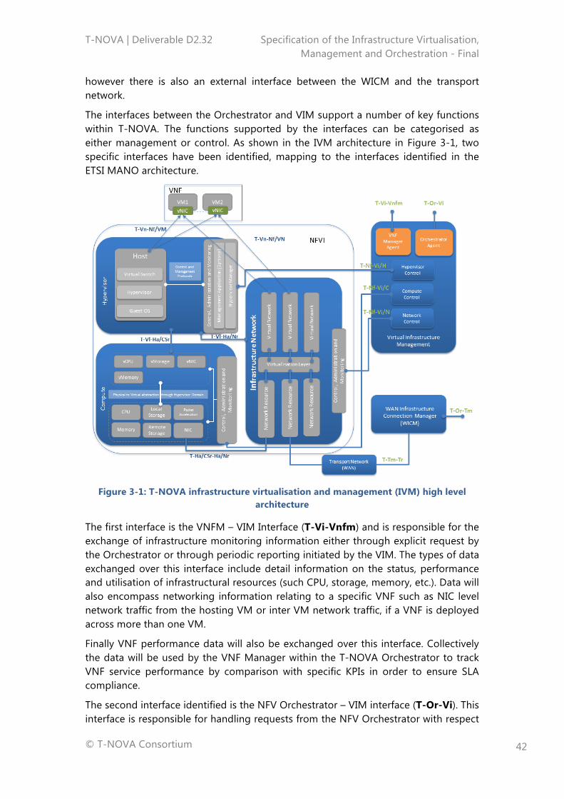
T-NOVA | Deliverable D2.32 Specification of the Infrastructure Virtualisation, Management and Orchestration - Final
© T-NOVA Consortium
42
however there is also an external interface between the WICM and the transport network.
The interfaces between the Orchestrator and VIM support a number of key functions within T-NOVA. The functions supported by the interfaces can be categorised as either management or control. As shown in the IVM architecture in Figure 3-1, two specific interfaces have been identified, mapping to the interfaces identified in the ETSI MANO architecture.
Figure 3-1: T-NOVA infrastructure virtualisation and management (IVM) high level
architecture
The first interface is the VNFM – VIM Interface (T-Vi-Vnfm) and is responsible for the exchange of infrastructure monitoring information either through explicit request by the Orchestrator or through periodic reporting initiated by the VIM. The types of data exchanged over this interface include detail information on the status, performance and utilisation of infrastructural resources (such CPU, storage, memory, etc.). Data will also encompass networking information relating to a specific VNF such as NIC level network traffic from the hosting VM or inter VM network traffic, if a VNF is deployed across more than one VM.
Finally VNF performance data will also be exchanged over this interface. Collectively the data will be used by the VNF Manager within the T-NOVA Orchestrator to track VNF service performance by comparison with specific KPIs in order to ensure SLA compliance.
The second interface identified is the NFV Orchestrator – VIM interface (T-Or-Vi). This interface is responsible for handling requests from the NFV Orchestrator with respect
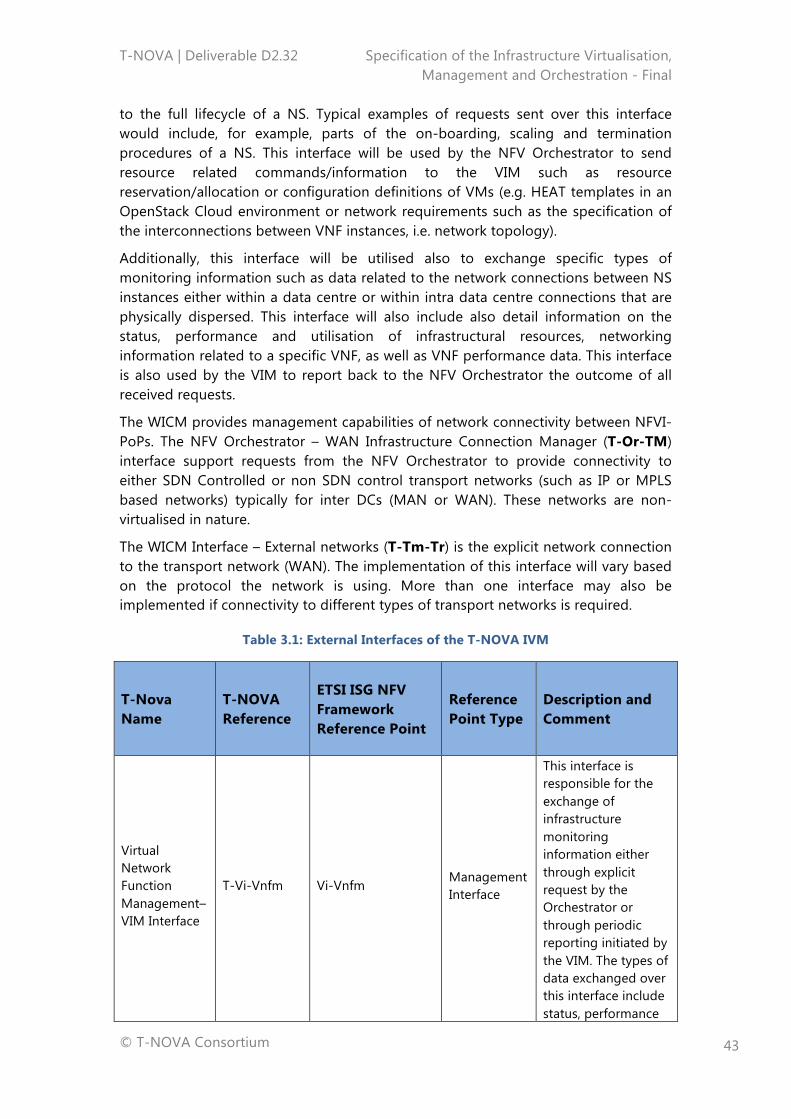
T-NOVA | Deliverable D2.32 Specification of the Infrastructure Virtualisation, Management and Orchestration - Final
© T-NOVA Consortium
43
to the full lifecycle of a NS. Typical examples of requests sent over this interface would include, for example, parts of the on-boarding, scaling and termination procedures of a NS. This interface will be used by the NFV Orchestrator to send resource related commands/information to the VIM such as resource reservation/allocation or configuration definitions of VMs (e.g. HEAT templates in an OpenStack Cloud environment or network requirements such as the specification of the interconnections between VNF instances, i.e. network topology).
Additionally, this interface will be utilised also to exchange specific types of monitoring information such as data related to the network connections between NS instances either within a data centre or within intra data centre connections that are physically dispersed. This interface will also include also detail information on the status, performance and utilisation of infrastructural resources, networking information related to a specific VNF, as well as VNF performance data. This interface is also used by the VIM to report back to the NFV Orchestrator the outcome of all received requests.
The WICM provides management capabilities of network connectivity between NFVI-PoPs. The NFV Orchestrator – WAN Infrastructure Connection Manager (T-Or-TM) interface support requests from the NFV Orchestrator to provide connectivity to either SDN Controlled or non SDN control transport networks (such as IP or MPLS based networks) typically for inter DCs (MAN or WAN). These networks are non-virtualised in nature.
The WICM Interface – External networks (T-Tm-Tr) is the explicit network connection to the transport network (WAN). The implementation of this interface will vary based on the protocol the network is using. More than one interface may also be implemented if connectivity to different types of transport networks is required.
Table 3.1: External Interfaces of the T-NOVA IVM
T-Nova Name
T-NOVA Reference
ETSI ISG NFV Framework Reference Point
Reference Point Type
Description and Comment
Virtual Network Function Management–VIM Interface
T-Vi-Vnfm Vi-Vnfm Management Interface
This interface is responsible for the exchange of infrastructure monitoring information either through explicit request by the Orchestrator or through periodic reporting initiated by the VIM. The types of data exchanged over this interface include status, performance
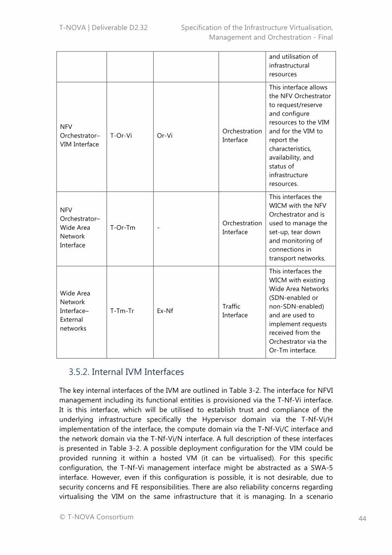
T-NOVA | Deliverable D2.32 Specification of the Infrastructure Virtualisation, Management and Orchestration - Final
© T-NOVA Consortium
44
and utilisation of infrastructural resources
NFV Orchestrator–VIM Interface
T-Or-Vi Or-Vi Orchestration Interface
This interface allows the NFV Orchestrator to request/reserve and configure resources to the VIM and for the VIM to report the characteristics, availability, and status of infrastructure resources.
NFV Orchestrator–Wide Area Network Interface
T-Or-Tm - Orchestration Interface
This interfaces the WICM with the NFV Orchestrator and is used to manage the set-up, tear down and monitoring of connections in transport networks.
Wide Area Network Interface–External networks
T-Tm-Tr Ex-Nf Traffic Interface
This interfaces the WICM with existing Wide Area Networks (SDN-enabled or non-SDN-enabled) and are used to implement requests received from the Orchestrator via the Or-Tm interface.
3.5.2. Internal IVM Interfaces
The key internal interfaces of the IVM are outlined in Table 3-2. The interface for NFVI management including its functional entities is provisioned via the T-Nf-Vi interface. It is this interface, which will be utilised to establish trust and compliance of the underlying infrastructure specifically the Hypervisor domain via the T-Nf-Vi/H implementation of the interface, the compute domain via the T-Nf-Vi/C interface and the network domain via the T-Nf-Vi/N interface. A full description of these interfaces is presented in Table 3-2. A possible deployment configuration for the VIM could be provided running it within a hosted VM (it can be virtualised). For this specific configuration, the T-Nf-Vi management interface might be abstracted as a SWA-5 interface. However, even if this configuration is possible, it is not desirable, due to security concerns and FE responsibilities. There are also reliability concerns regarding virtualising the VIM on the same infrastructure that it is managing. In a scenario
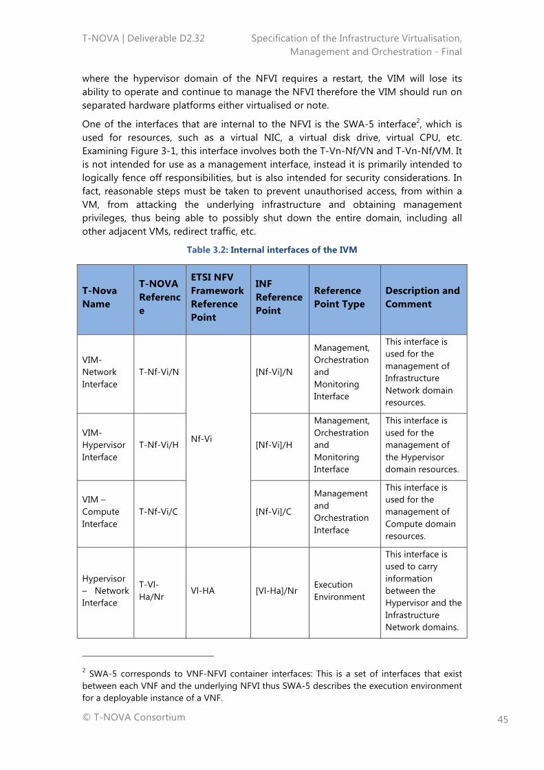
T-NOVA | Deliverable D2.32 Specification of the Infrastructure Virtualisation, Management and Orchestration - Final
© T-NOVA Consortium
45
where the hypervisor domain of the NFVI requires a restart, the VIM will lose its ability to operate and continue to manage the NFVI therefore the VIM should run on separated hardware platforms either virtualised or note.
One of the interfaces that are internal to the NFVI is the SWA-5 interface2, which is used for resources, such as a virtual NIC, a virtual disk drive, virtual CPU, etc. Examining Figure 3-1, this interface involves both the T-Vn-Nf/VN and T-Vn-Nf/VM. It is not intended for use as a management interface, instead it is primarily intended to logically fence off responsibilities, but is also intended for security considerations. In fact, reasonable steps must be taken to prevent unauthorised access, from within a VM, from attacking the underlying infrastructure and obtaining management privileges, thus being able to possibly shut down the entire domain, including all other adjacent VMs, redirect traffic, etc.
Table 3.2: Internal interfaces of the IVM
T-Nova Name
T-NOVA Reference
ETSI NFV Framework Reference Point
INF Reference Point
Reference Point Type
Description and Comment
VIM-Network Interface
T-Nf-Vi/N
Nf-Vi
[Nf-Vi]/N
Management, Orchestration and Monitoring Interface
This interface is used for the management of Infrastructure Network domain resources.
VIM-Hypervisor Interface
T-Nf-Vi/H [Nf-Vi]/H
Management, Orchestration and Monitoring Interface
This interface is used for the management of the Hypervisor domain resources.
VIM – Compute Interface
T-Nf-Vi/C [Nf-Vi]/C
Management and Orchestration Interface
This interface is used for the management of Compute domain resources.
Hypervisor– Network Interface
T-Vl-Ha/Nr
Vl-HA [Vl-Ha]/Nr Execution Environment
This interface is used to carry information between the Hypervisor and the Infrastructure Network domains.
2 SWA-5 corresponds to VNF-NFVI container interfaces: This is a set of interfaces that exist between each VNF and the underlying NFVI thus SWA-5 describes the execution environment for a deployable instance of a VNF.
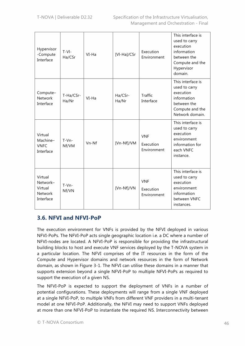
T-NOVA | Deliverable D2.32 Specification of the Infrastructure Virtualisation, Management and Orchestration - Final
© T-NOVA Consortium
46
Hypervisor-Compute Interface
T-Vl-Ha/CSr
VI-Ha [Vl-Ha]/CSr Execution Environment
This interface is used to carry execution information between the Compute and the Hypervisor domain.
Compute– Network Interface
T-Ha/CSr-Ha/Nr
VI-Ha Ha/CSr-Ha/Nr
Traffic Interface
This interface is used to carry execution information between the Compute and the Network domain.
Virtual Machine–VNFC Interface
T-Vn-Nf/VM
Vn-Nf [Vn-Nf]/VM
VNF
Execution Environment
This interface is used to carry execution environment information for each VNFC instance.
Virtual Network–Virtual Network Interface
T-Vn-Nf/VN
[Vn-Nf]/VN
VNF
Execution Environment
This interface is used to carry execution environment information between VNFC instances.
3.6. NFVI and NFVI-PoP
The execution environment for VNFs is provided by the NFVI deployed in various NFVI-PoPs. The NFVI-PoP acts single geographic location i.e. a DC where a number of NFVI-nodes are located. A NFVI-PoP is responsible for providing the infrastructural building blocks to host and execute VNF services deployed by the T-NOVA system in a particular location. The NFVI comprises of the IT resources in the form of the Compute and Hypervisor domains and network resources in the form of Network domain, as shown in Figure 3-1. The NFVI can utilise these domains in a manner that supports extension beyond a single NFVI-PoP to multiple NFVI-PoPs as required to support the execution of a given NS.
The NFVI-PoP is expected to support the deployment of VNFs in a number of potential configurations. These deployments will range from a single VNF deployed at a single NFVI-PoP, to multiple VNFs from different VNF providers in a multi-tenant model at one NFVI-PoP. Additionally, the NFVI may need to support VNFs deployed at more than one NFVI-PoP to instantiate the required NS. Interconnectivity between
T-NOVA | Deliverable D2.32 Specification of the Infrastructure Virtualisation, Management and Orchestration - Final
© T-NOVA Consortium
47
these PoPs is provisioned and managed in the case of T-NOVA by the WICM module, which is similar in function to the WAN Controller in the ETSI MANO architecture [9] (see subsection 3.8).
The network access capacity required at a particular NFVI-PoP will depend on the network service workload type, the number and capacity of the VNFs instantiated on the NFVI. The management and orchestration of virtualised resources should be able to handle NFVI resources in a single NFVI-PoP as well as when distributed across multiple NFVI-PoPs. Management of the NFVI is provided by the VIM through domain interfaces (T-Nf-Vi) as shown in Figure 3-1. The VIM also provides the intermediate interfaces between the Orchestrator and the NFVI (T-Or-Vi and T-Vi-VNFM). The NFVI will execute requests from the Orchestrator via the VIM relating to the lifecycle management of VNFs such as deployment scale in/out and termination.
The following sections describe the architecture and the respective internal components of the NFVI, namely the compute, hypervisor and network domains. The interfaces required to implement an overall functional architecture for the T-NOVA NFVI system are also described.
3.6.1. IT Resources
The T-NOVA IT Resources encompasses the compute and hypervisor domains of the NFVI. These domains have their origins in traditional enterprise IT environments and more recently in the deployment of cloud computing environments. In order to support the development of NFV architectural approaches in carrier grade environments, IT resources and capabilities have been embraced in these environments to support the deployment of VNFs. However the functionality, capabilities and how these IT resources are composed within virtualised network architectures need to be carefully considered. The enterprise origins of these technologies often have inherent gaps in capability such as line-rate packet processing performance limitations. These gaps can influence architectural decisions and may require innovative solutions to address any identified gaps for VNF service deployment. The following sections discuss the compute and hypervisor domain architecture considerations and the proposed approach in the context of the T-NOVA system architecture.
3.6.1.1. Compute Domain
The Compute Domain is one of three domains constituting the NFVI and consists of servers, NICs, accelerators, storage, racks, and associated physical components within the rack(s) related to the NFVI, including the networking Top of Rack (ToR) switch. The Compute domain may be deployed as a number of physical nodes (e.g. Compute and Storage Nodes) interconnected by Network Nodes (devices) within an NFVI-PoP.
Traditionally the compute environment within the telecoms domain has been heterogeneous based around a variety around microprocessor architectures such as MIPS, PowerPC, SPARC, etc. with tight coupling between the microprocessor and the software implementation. Many traditional telecommunication systems are built in
T-NOVA | Deliverable D2.32 Specification of the Infrastructure Virtualisation, Management and Orchestration - Final
© T-NOVA Consortium
48
C/C++ technology with high interdependence on the underlying processing infrastructure and a specific instruction set.
As the first generation of commercial VNFs have become available based on adaption of the software from previous fixed appliances to a version that can run in virtualised X86 environments some performance difficulties have been encountered. While virtualisation decouples software and hardware from a deployment point of view, it does not do it from a development point of view. Selection of an appropriate cross compiler for the target platform (e.g. X86) may address some of the issues. However in order to achieve optimal performance, a proper redesign of the software may be required to ensure appropriate use of specific capabilities, for example hyper threading in X86 processors. The application may also need to use certain software libraries to improve the performance of certain actions such as packet processing. However VNFs running on SHV servers generally will have some of trade trade-off between flexibility, ease of development & deployment, performance etc. in comparison to custom hardware platforms.
The compute domain architecture should have the capability to support distributed virtual appliances that can be hosted across multiple compute platforms as required by specific SLAs of network services. Moreover storage technologies and management solutions are included in the domain and show a large degree of variability in terms of different technologies; scalability and performance (see start of the art review). Depending on the workloads and use-cases the choice of storage technology is likely to be specific to certain workload types.
Another important objective of the compute domain is to expose hardware statistics of the compute node with high temporal resolution. The VIM communicates directly to the compute domain and through the hypervisor to access all the hardware metrics, which can be static or dynamic in nature.
Static metrics expose compute node characteristics which do not change or change slowly (e.g. once a day). These metrics ultimately act as a first order filter for selecting/provisioning a node for deploying a VNF. Static metrics are obtained from reading OS and ACPI tables. The Advanced Configuration and Power Interface (ACPI) specification provides an open standard for device configuration and power management by the operating system. Additional metrics may be stored in local structures provisioned by server vendors or system administrators. For example compute node performance index, energy efficiency index, geographic location, specific features enabled/supported, security level, etc.
An Orchestrator can identify a candidate platform based on static metrics, however in order to actually instantiate a VNF additional dynamic metrics are required, e.g. CPU utilisation, memory, I/O headroom currently available etc. These metrics could be provided on a per-query basis or the compute node could proactively update hypervisor domain at regular intervals.
Heterogeneous Compute Architectures
A VNF developed for a target compute architecture needs to be fully optimised and validated prior to rollout. This process will also need to be repeated on a per
T-NOVA | Deliverable D2.32 Specification of the Infrastructure Virtualisation, Management and Orchestration - Final
© T-NOVA Consortium
49
compute architecture basis. While the initial focus has been on X86 compute architectures, recently there has been interest in the use of co-processors such GPUs or FPGAs to accelerate certain VNF workloads: some workloads can experience performance benefits by having access to different processing solutions from a variety of silicon vendors including network processors and general-purpose co-processors. The move towards more heterogeneous cloud computing environments is starting to gain attention, as standard X86 processors may have performance limitations for certain workloads tasks e.g. high speed packet processing. This has led DC equipment vendors to investigate the use of alternative compute architectures provisioned in either in a standalone manner or coupled with X86 processors to enhance their offerings. In defining heterogeneous compute domain architectures for T-NOVA, we divided devices into two main categories:
• Devices which can only operate in conjunction with a host CPU, like GPUs, multi-integrated cores (MIC) and Micron’s Automata processor;
• Devices which can operate in a stand-alone fashion, like FPGAs and FPGA SoCs (although FPGAs and FPGA SoCs can also act as devices attached to a CPU-controlled system).
For the first class of devices we can derive a compute node architecture, where the compute node is complemented by a co-processor, which can be any of the four technologies mentioned above (in the FPGA and FPGA SoC cases, they will, act as slave devices to the processor). The extent to which the accelerator resources themselves are virtualised is left to each specific implementation, though such a solution is known to improve the performance of the accelerator hardware. It must be noted that such a solution is only available for GPUs (e.g. nVidia’s GRID), but not for FPGAs or the automata processor. This general architecture leaves a lot of the implementation choices open. For example the interconnection of the CPU and the co-processor could be implemented either over PCIe or over a direct link like Quick Path Interconnect (QPI) or division of the memory between the CPU and the co-processor. In any scenario, the system must be able to adhere to the requirements for the compute nodes as outlined down in Annex B.
The second class of devices is based around an FPGA SoC, which is an FPGA that integrates one or more processor cores in the same silicon die. Devices like these are available from all major FPGA vendors. In this case, the processing system on the FPGA SoC runs a Hypervisor on which OS’ and applications are executed. To a large extent the same considerations as in the previous scenario apply, both in terms of interconnection of components and virtualisation of accelerator resources. The important difference here is the degree of integration, since the whole heterogeneous compute node resides within one physical device.
Key Components of the Compute Domain
The main components of the Compute domain’s architecture are:
• CPU and Accelerator: A general-purpose compute architecture is considered based on commercial x86 server clusters. Additionally co-processors cards/FPGAs and GPUs are also considered for application specific workloads
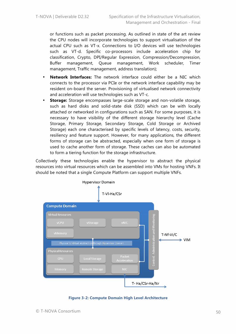
T-NOVA | Deliverable D2.32 Specification of the Infrastructure Virtualisation, Management and Orchestration - Final
© T-NOVA Consortium
50
or functions such as packet processing. As outlined in state of the art review the CPU nodes will incorporate technologies to support virtualisation of the actual CPU such as VT-x. Connections to I/O devices will use technologies such as VT-d. Specific co-processors include acceleration chip for classification, Crypto, DPI/Regular Expression, Compression/Decompression, Buffer management, Queue management, Work scheduler, Timer management, Traffic management, address translation);
• Network Interfaces: The network interface could either be a NIC which connects to the processor via PCIe or the network interface capability may be resident on-board the server. Provisioning of virtualised network connectivity and acceleration will use technologies such as VT-c.
• Storage: Storage encompasses large-scale storage and non-volatile storage, such as hard disks and solid-state disk (SSD) which can be with locally attached or networked in configurations such as SAN. For some purposes, it is necessary to have visibility of the different storage hierarchy level (Cache Storage, Primary Storage, Secondary Storage, Cold Storage or Archived Storage) each one characterised by specific levels of latency, costs, security, resiliency and feature support. However, for many applications, the different forms of storage can be abstracted, especially when one form of storage is used to cache another form of storage. These caches can also be automated to form a tiering function for the storage infrastructure.
Collectively these technologies enable the hypervisor to abstract the physical resources into virtual resources which can be assembled into VMs for hosting VNFs. It should be noted that a single Compute Platform can support multiple VNFs.
Figure 3-2: Compute Domain High Level Architecture
T-NOVA | Deliverable D2.32 Specification of the Infrastructure Virtualisation, Management and Orchestration - Final
© T-NOVA Consortium
51
Compute Domain Interfaces
The compute domain presents three external interfaces:
• The T-Nf-Vi/C - used by the VIM to manage the compute and storage portion of the NFVI. It is the reference point between the management and orchestration functions in compute domain and the management and orchestration functions in the virtual infrastructure management (VIM);
• The T-[Vi-Ha]/CSr interface is the interface between the compute domain and the hypervisor domain. It is primarily used by the hypervisor/OS to gain insight into the available physical resources of the compute domain;
• The T-HA/CSr-Ha/Nr interface is used to carry execution information between the Compute and the Network domain.
Orchestration and management of the NFVI is strictly implemented via the T-Nf-Vi interfaces. The implementation of the interface must match the requirements outlined in Annex B in addition to having the general characteristics of being dedicated and secure. This interface is utilised to establish trust and compliance between the VIM and the underlying compute infrastructure. The interface is exposed by management functions of the compute node and allows both control and monitoring of the compute domain. With regard to monitoring, agents are installed both at the host OS (to measure physical resources) as well as (optionally) at the guest OSs (to measure virtualised resources associated with a specific VNFC). The latter metrics are of particular interest to T-NOVA operations, since they provide an indication of the resources consumed by a VNFC instance and are directly used for service monitoring. Heterogeneous compute resources need to provide additional methods to extract the appropriate metrics from the devices and to send them via the T-Nf-Vi interfaces. Application performance such as SLA compliance depends on a variety metrics such as resource and system level metrics. The ability to measure application performance and consumption of resources plays a critical role in operational activities such as customer billing. Furthermore, statistical processing of VNFC metrics will be exploited to indicate a particular malfunction. Metrics to be collected at both physical compute node and VM include CPU utilisation, memory utilisation, network interface utilisation, processed traffic bandwidth, number of processes, etc.
3.6.1.2. Hypervisor Domain
The hypervisor domain is the part of the T-NOVA architecture that provides the virtualised compute environment to VNFs. Since the hypervisor domain embraces different types of hosts, with different Guest OSs and/or hypervisors, it is important to manage interoperability issues appropriately. Issues relating to the virtualisation of VNFs on technologies from different vendors need to be carefully considered.
The primary goal of the hypervisor domain is therefore to manage the heterogeneity of technologies from different vendors, thus providing an interoperable cloud environment to the VNFs. In that sense, the hypervisor domain provides an abstraction layer between the VIM (which controls, monitors and administrates the
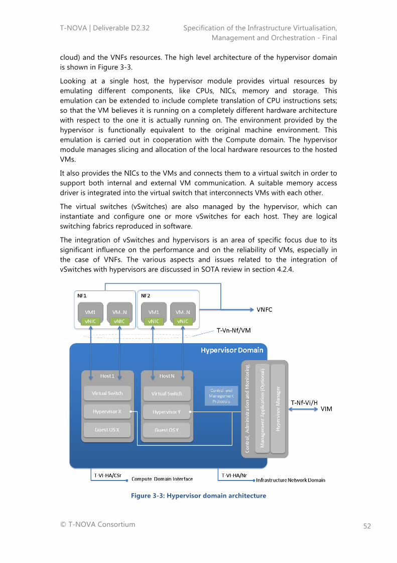
T-NOVA | Deliverable D2.32 Specification of the Infrastructure Virtualisation, Management and Orchestration - Final
© T-NOVA Consortium
52
cloud) and the VNFs resources. The high level architecture of the hypervisor domain is shown in Figure 3-3.
Looking at a single host, the hypervisor module provides virtual resources by emulating different components, like CPUs, NICs, memory and storage. This emulation can be extended to include complete translation of CPU instructions sets; so that the VM believes it is running on a completely different hardware architecture with respect to the one it is actually running on. The environment provided by the hypervisor is functionally equivalent to the original machine environment. This emulation is carried out in cooperation with the Compute domain. The hypervisor module manages slicing and allocation of the local hardware resources to the hosted VMs.
It also provides the NICs to the VMs and connects them to a virtual switch in order to support both internal and external VM communication. A suitable memory access driver is integrated into the virtual switch that interconnects VMs with each other.
The virtual switches (vSwitches) are also managed by the hypervisor, which can instantiate and configure one or more vSwitches for each host. They are logical switching fabrics reproduced in software.
The integration of vSwitches and hypervisors is an area of specific focus due to its significant influence on the performance and on the reliability of VMs, especially in the case of VNFs. The various aspects and issues related to the integration of vSwitches with hypervisors are discussed in SOTA review in section 4.2.4.
Figure 3-3: Hypervisor domain architecture
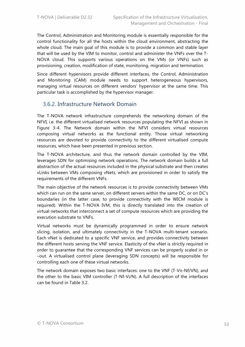
T-NOVA | Deliverable D2.32 Specification of the Infrastructure Virtualisation, Management and Orchestration - Final
© T-NOVA Consortium
53
The Control, Administration and Monitoring module is essentially responsible for the control functionality for all the hosts within the cloud environment, abstracting the whole cloud. The main goal of this module is to provide a common and stable layer that will be used by the VIM to monitor, control and administer the VNFs over the T-NOVA cloud. This supports various operations on the VMs (or VNFs) such as provisioning, creation, modification of state, monitoring, migration and termination.
Since different hypervisors provide different interfaces, the Control, Administration and Monitoring (CAM) module needs to support heterogeneous hypervisors, managing virtual resources on different vendors’ hypervisor at the same time. This particular task is accomplished by the hypervisor manager.
3.6.2. Infrastructure Network Domain
The T-NOVA network infrastructure comprehends the networking domain of the NFVI, i.e. the different virtualised network resources populating the NFVI as shown in Figure 3-4. The Network domain within the NFVI considers virtual resources composing virtual networks as the functional entity. Those virtual networking resources are devoted to provide connectivity to the different virtualised compute resources, which have been presented in previous section.
The T-NOVA architecture, and thus the network domain controlled by the VIM, leverages SDN for optimising network operations. The network domain builds a full abstraction of the actual resources included in the physical substrate and then creates vLinks between VMs composing vNets, which are provisioned in order to satisfy the requirements of the different VNFs.
The main objective of the network resources is to provide connectivity between VMs which can run on the same server, on different servers within the same DC, or on DC’s boundaries (in the latter case, to provide connectivity with the WICM module is required). Within the T-NOVA IVM, this is directly translated into the creation of virtual networks that interconnect a set of compute resources which are providing the execution substrate to VNFs.
Virtual networks must be dynamically programmed in order to ensure network slicing, isolation, and ultimately connectivity in the T-NOVA multi-tenant scenario. Each vNet is dedicated to a specific VNF service, and provides connectivity between the different hosts serving the VNF service. Elasticity of the vNet is strictly required in order to guarantee that the corresponding VNF services can be properly scaled in or –out. A virtualised control plane (leveraging SDN concepts) will be responsible for controlling each one of these virtual networks.
The network domain exposes two basic interfaces: one to the VNF (T-Vn-Nf/VN), and the other to the basic VIM controller (T-Nf-Vi/N). A full description of the interfaces can be found in Table 3.2.
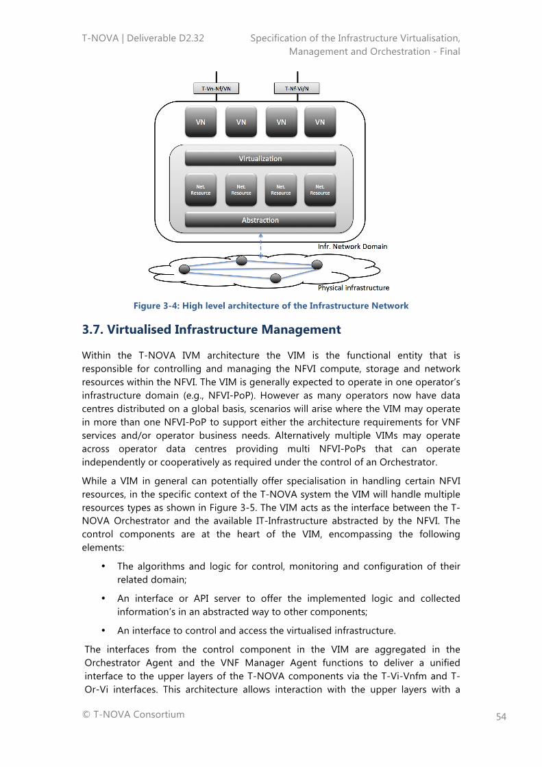
T-NOVA | Deliverable D2.32 Specification of the Infrastructure Virtualisation, Management and Orchestration - Final
© T-NOVA Consortium
54
Figure 3-4: High level architecture of the Infrastructure Network
3.7. Virtualised Infrastructure Management
Within the T-NOVA IVM architecture the VIM is the functional entity that is responsible for controlling and managing the NFVI compute, storage and network resources within the NFVI. The VIM is generally expected to operate in one operator’s infrastructure domain (e.g., NFVI-PoP). However as many operators now have data centres distributed on a global basis, scenarios will arise where the VIM may operate in more than one NFVI-PoP to support either the architecture requirements for VNF services and/or operator business needs. Alternatively multiple VIMs may operate across operator data centres providing multi NFVI-PoPs that can operate independently or cooperatively as required under the control of an Orchestrator.
While a VIM in general can potentially offer specialisation in handling certain NFVI resources, in the specific context of the T-NOVA system the VIM will handle multiple resources types as shown in Figure 3-5. The VIM acts as the interface between the T-NOVA Orchestrator and the available IT-Infrastructure abstracted by the NFVI. The control components are at the heart of the VIM, encompassing the following elements:
• The algorithms and logic for control, monitoring and configuration of their related domain;
• An interface or API server to offer the implemented logic and collected information’s in an abstracted way to other components;
• An interface to control and access the virtualised infrastructure.
The interfaces from the control component in the VIM are aggregated in the Orchestrator Agent and the VNF Manager Agent functions to deliver a unified interface to the upper layers of the T-NOVA components via the T-Vi-Vnfm and T-Or-Vi interfaces. This architecture allows interaction with the upper layers with a
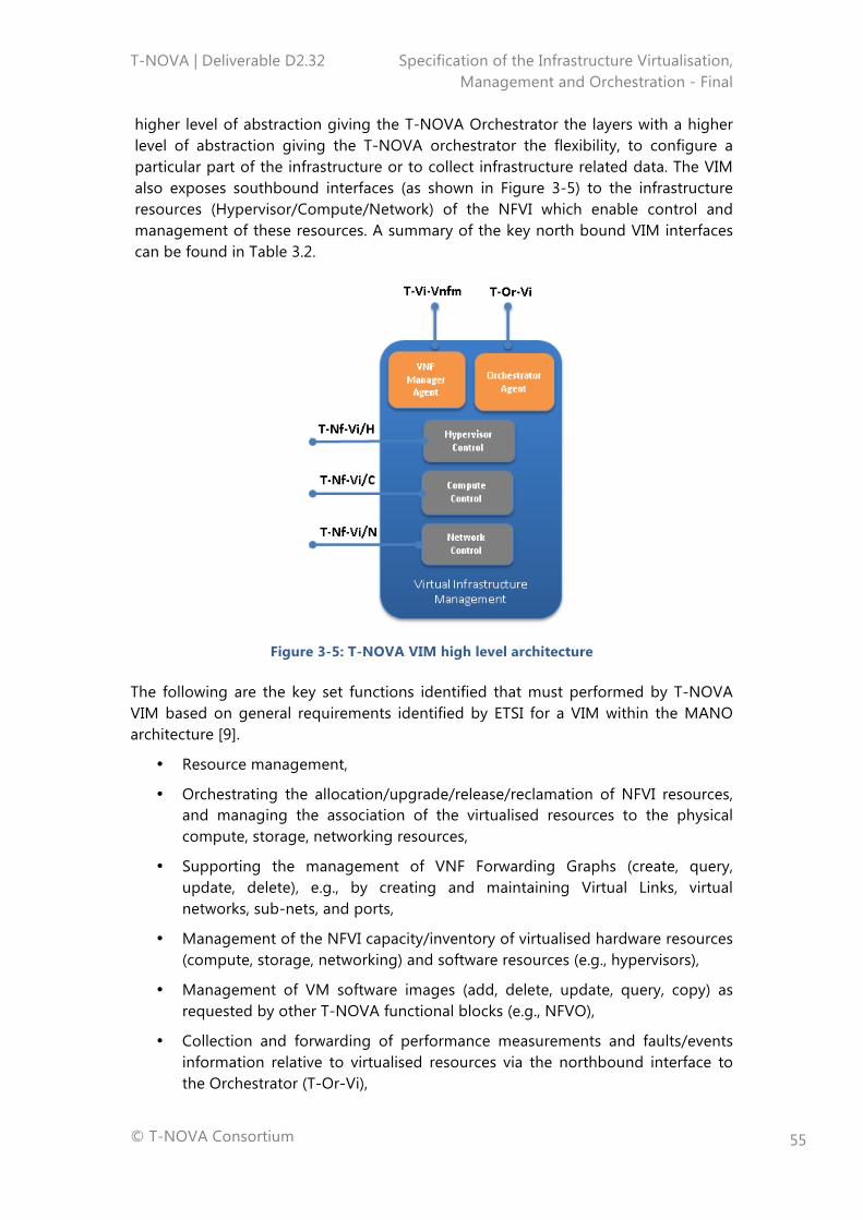
T-NOVA | Deliverable D2.32 Specification of the Infrastructure Virtualisation, Management and Orchestration - Final
© T-NOVA Consortium
55
higher level of abstraction giving the T-NOVA Orchestrator the layers with a higher level of abstraction giving the T-NOVA orchestrator the flexibility, to configure a particular part of the infrastructure or to collect infrastructure related data. The VIM also exposes southbound interfaces (as shown in Figure 3-5) to the infrastructure resources (Hypervisor/Compute/Network) of the NFVI which enable control and management of these resources. A summary of the key north bound VIM interfaces can be found in Table 3.2.
Figure 3-5: T-NOVA VIM high level architecture
The following are the key set functions identified that must performed by T-NOVA VIM based on general requirements identified by ETSI for a VIM within the MANO architecture [9].
• Resource management,
• Orchestrating the allocation/upgrade/release/reclamation of NFVI resources, and managing the association of the virtualised resources to the physical compute, storage, networking resources,
• Supporting the management of VNF Forwarding Graphs (create, query, update, delete), e.g., by creating and maintaining Virtual Links, virtual networks, sub-nets, and ports,
• Management of the NFVI capacity/inventory of virtualised hardware resources (compute, storage, networking) and software resources (e.g., hypervisors),
• Management of VM software images (add, delete, update, query, copy) as requested by other T-NOVA functional blocks (e.g., NFVO),
• Collection and forwarding of performance measurements and faults/events information relative to virtualised resources via the northbound interface to the Orchestrator (T-Or-Vi),
T-NOVA | Deliverable D2.32 Specification of the Infrastructure Virtualisation, Management and Orchestration - Final
© T-NOVA Consortium
56
• Management of catalogues of virtualised resources that can be consumed from the NFVI. The elements in the catalogue may be in the form of virtualised resource configurations (virtual CPU configurations, types of network connectivity (e.g., L2, L3), etc.), and/or templates (e.g., a virtual machine with 2 virtual CPUs and 2 GB of virtual memory).
The high level architecture for the T-NOVA VIM architecture reflects these key functions.
3.7.1. IT Resource Management and Monitoring
In the T-NOVA system we distinguish between IT and virtualised network resources Also from a management and control perspective this categorisation is clearly visible in the architectural design of the VIM. In fact, on the one hand, the VIM provides to the Orchestration layer a unified access point to all infrastructural resources at an abstracted level, but, on the other hand, internally the control modules are explicitly split into Compute and Hypervisor Control managing the IT resources, whereas the Network Control module manages the network resources. This architectural choice allows the T-NOVA system to manage them according to different requirements and needs (in terms of performance, time constraints, and so forth) The following subsections discuss the respective management and control needs of the hypervisor and compute resources within the VIM and their relationship to the NFVI.
3.7.1.1. Hypervisor Management
The hypervisor control function is responsible for providing high level control and configuration capability that is independent of the technology implementation within the hypervisor domain. The interface to the hypervisor domain (T-Nf-Vi/H) provides the necessary level of abstraction to the specifics of the underlying hypervisor. The hypervisor control component provides the basic commands like start, stop, reboot etc. and offers these commands through an API server to the VIM. Specific commands related to a particular hypervisor implementation may also be supported on case by case basis through the same API server allowing finer performance tuning. Additionally the hypervisor controller can implement a query API that can be used to provide detailed information such as configuration details, version numbers etc.
The network configuration of a newly created VM is usually configured by a script that runs at boot-time or can be done manually via a CLI after the VM has booted. The hypervisor control component will offer the capability to implement a network configuration during VM instantiation thus enabling a higher degree of automation which is important for service provider operations. The hypervisor controller is able to configure the VM, provided the hypervisor supports the action, the desired network settings before the first boot of the OS.
The reliability capabilities inside the hypervisor controller have an important role as custom configurations can be requested by the T-NOVA Orchestrator. Their primary role is to prevent the user of the API from placing the hypervisor in an inconsistent or error state leaving it unable to manage or respond to the VMs under its control. The module may also play a role in managing issues such as misconfiguration,
T-NOVA | Deliverable D2.32 Specification of the Infrastructure Virtualisation, Management and Orchestration - Final
© T-NOVA Consortium
57
compromised commands or hypervisor options that do not work well with the allocated hardware.
Additionally, the hypervisor provides VM resource metrics to be used for service monitoring, in addition to the metrics collected at the compute domain (see next section).
3.7.1.2. Computing Resources Management
A key functionality of the compute domain management will be the collection and processing of the monitoring metrics collected by both the physical compute nodes as well as the VMs (VNFCs). A dedicated monitoring manager is envisaged, to which monitoring agents will connect to communicate compute domain resource metrics’ measured values. At the monitoring manager, these metrics will undergo statistical processing in order to extract additional information such as fluctuation, distribution and correlation. This processing will provide useful information about the behaviour of each VNF component and will contribute towards the early detection of possible VNFC malfunctions or performance issues. This will be the case e.g. if some measurements fall outside the normal VNF load curve (e.g. if CPU utilisation rises abnormally even though processed network traffic volume does not).
The placement of a VM on a compute resource is a critical task and the compute controller carries out this function using a placement scheduler. This scheduler will, if no further options are specified, make a decision based on the requirements of the infrastructure provider and place the VM in an automated fashion. To influence this decision making process, the scheduler will have a filter API that can be used. Details related to the desired SLA or specific hardware and software requirements can be passed to the filter. The main filter categories that influence the decision process by the scheduler are:
• Specific hardware requirements like CPU speed or type of disk,
• Specific software requirements like the host OS or the hypervisor,
• Current load and performance metrics of the compute node such as average CPU utilisation rate etc.,
• Financial considerations such as newest hardware or most energy efficient hardware.
A further core task of the compute controller is to provide specific management capabilities of the VMs for the Orchestrator especially where the operations overlap with hypervisor and network controller actions. Such tasks include:
• Creation and deletion of a VM,
• Rebuilding, suspend and pause a VM,
• Migrating a VM from one compute node to another compute node,
• Resizing a VM.
Creation of a VM requires close interaction with the base image repository that contains the basic unmodified OS images.
T-NOVA | Deliverable D2.32 Specification of the Infrastructure Virtualisation, Management and Orchestration - Final
© T-NOVA Consortium
58
The capability to enable infrastructure administrators to carry out routine maintenance and administration tasks on compute nodes is required. For example, the administrators may need to migrate VMs on a physical compute node to another one as part of an infrastructure upgrade activity. Other potential action may include interaction with the scheduler and filters in order to modify the configuration of a VM or set of VMs to maintain an associated SLA for a VNF service running on the VMs. These types of functionalities can also be implemented in an automated manner in order to support not only management activities but also automatic SLA fulfilment.
3.7.2. Infrastructure Network Resources Management and Monitoring
The Network Control functional block within the VIM is responsible for configuring and managing the SDN-compatible network elements to provide an abstracted platform for running SDN applications (i.e. network virtualisation, load balancing, access control etc.).
In order to meet specific VNF services’ requirements, the network elements, physical and virtual, need to be properly programmed by the Network Control function to ensure appropriate network slicing, isolation and connectivity in a multi-tenant environment. In this way, the network will be properly partitioned and shared among several vNets, each dedicated to a specific VNF service. In the T-NOVA architecture there is an explicit distinction between virtual and physical network control domains: the virtual network control domain is managed by the VIM, whereas the physical network control domain is managed by the WICM entity (discussed in next section).
The virtualisation of the Network Control is intended to address scalability and centralisation issues affecting the SDN control plane in large network infrastructures. The proposed approach considers a cluster of controllers to manage the network elements, using a distributed data store to maintain a global view of the network. By exploiting cloud-computing capabilities, the cluster can easily scale through the deployment of new CP instances on VMs, as the demands on the SDN control plane grow. In this regard, the SDN Control Plane can offer elasticity, auto-scaling and computational load balancing.
In order to guarantee efficient CP virtualisation, a SDN Control Plane Coordinator is expected to manage and monitor each CP instance, balancing the distribution of the overall workload to multiple CP instances.
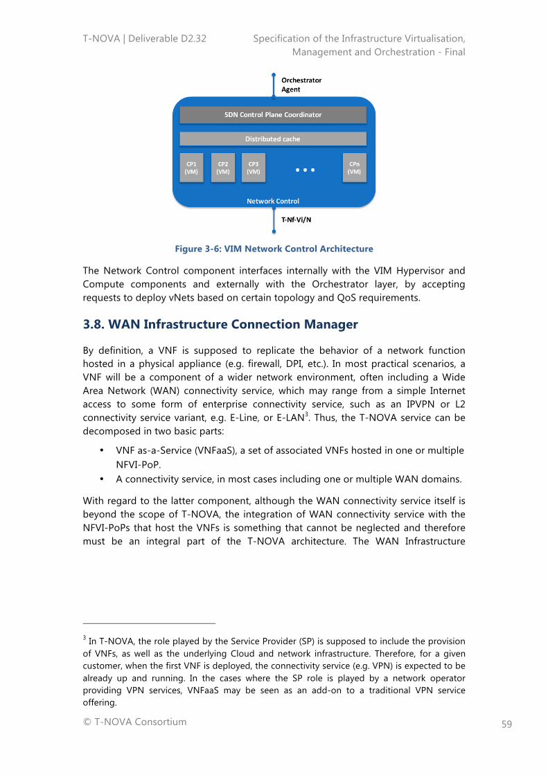
T-NOVA | Deliverable D2.32 Specification of the Infrastructure Virtualisation, Management and Orchestration - Final
© T-NOVA Consortium
59
Figure 3-6: VIM Network Control Architecture
The Network Control component interfaces internally with the VIM Hypervisor and Compute components and externally with the Orchestrator layer, by accepting requests to deploy vNets based on certain topology and QoS requirements.
3.8. WAN Infrastructure Connection Manager
By definition, a VNF is supposed to replicate the behavior of a network function hosted in a physical appliance (e.g. firewall, DPI, etc.). In most practical scenarios, a VNF will be a component of a wider network environment, often including a Wide Area Network (WAN) connectivity service, which may range from a simple Internet access to some form of enterprise connectivity service, such as an IPVPN or L2 connectivity service variant, e.g. E-Line, or E-LAN3. Thus, the T-NOVA service can be decomposed in two basic parts:
• VNF as-a-Service (VNFaaS), a set of associated VNFs hosted in one or multiple NFVI-PoP.
• A connectivity service, in most cases including one or multiple WAN domains.
With regard to the latter component, although the WAN connectivity service itself is beyond the scope of T-NOVA, the integration of WAN connectivity service with the NFVI-PoPs that host the VNFs is something that cannot be neglected and therefore must be an integral part of the T-NOVA architecture. The WAN Infrastructure
3 In T-NOVA, the role played by the Service Provider (SP) is supposed to include the provision of VNFs, as well as the underlying Cloud and network infrastructure. Therefore, for a given customer, when the first VNF is deployed, the connectivity service (e.g. VPN) is expected to be already up and running. In the cases where the SP role is played by a network operator providing VPN services, VNFaaS may be seen as an add-on to a traditional VPN service offering.
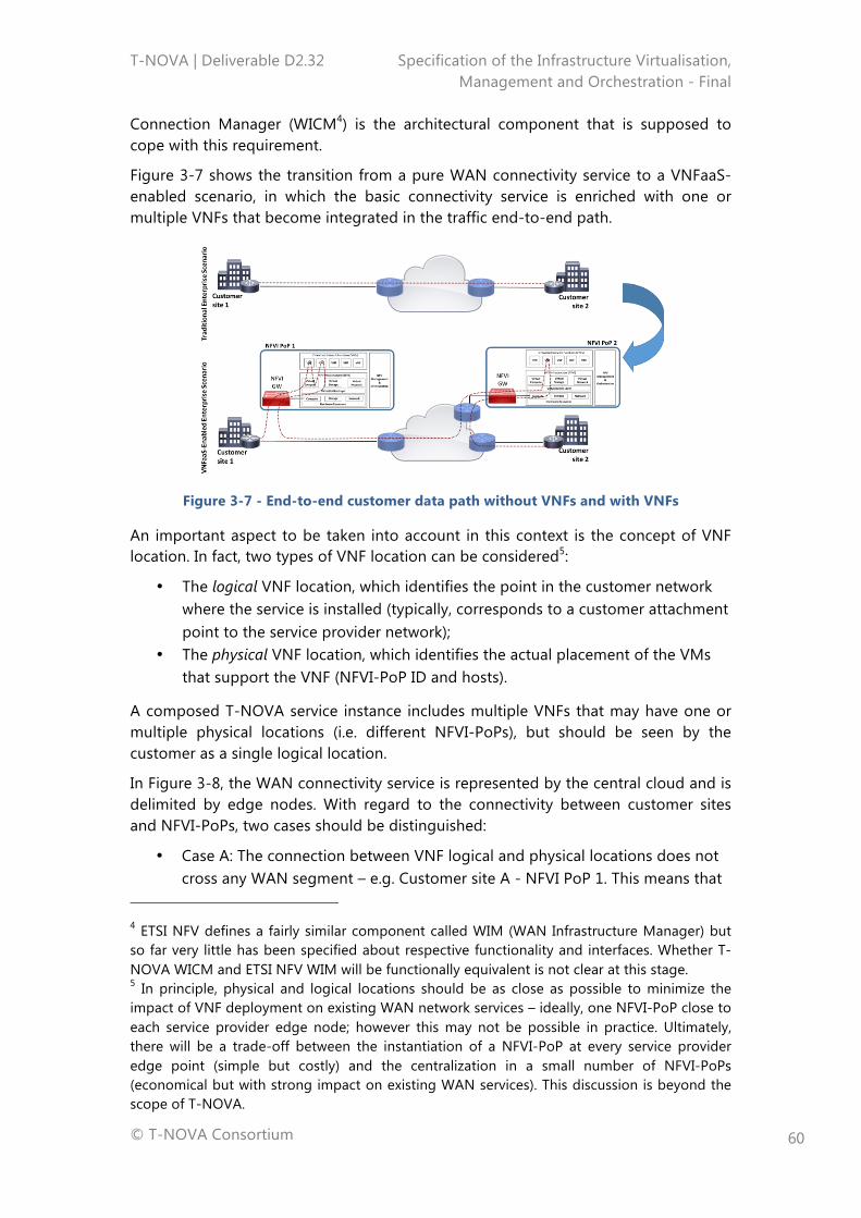
T-NOVA | Deliverable D2.32 Specification of the Infrastructure Virtualisation, Management and Orchestration - Final
© T-NOVA Consortium
60
Connection Manager (WICM4) is the architectural component that is supposed to cope with this requirement.
Figure 3-7 shows the transition from a pure WAN connectivity service to a VNFaaS-enabled scenario, in which the basic connectivity service is enriched with one or multiple VNFs that become integrated in the traffic end-to-end path.
Figure 3-7 - End-to-end customer data path without VNFs and with VNFs
An important aspect to be taken into account in this context is the concept of VNF location. In fact, two types of VNF location can be considered5:
• The logical VNF location, which identifies the point in the customer network where the service is installed (typically, corresponds to a customer attachment point to the service provider network);
• The physical VNF location, which identifies the actual placement of the VMs that support the VNF (NFVI-PoP ID and hosts).
A composed T-NOVA service instance includes multiple VNFs that may have one or multiple physical locations (i.e. different NFVI-PoPs), but should be seen by the customer as a single logical location.
In Figure 3-8, the WAN connectivity service is represented by the central cloud and is delimited by edge nodes. With regard to the connectivity between customer sites and NFVI-PoPs, two cases should be distinguished:
• Case A: The connection between VNF logical and physical locations does not cross any WAN segment – e.g. Customer site A - NFVI PoP 1. This means that
4 ETSI NFV defines a fairly similar component called WIM (WAN Infrastructure Manager) but so far very little has been specified about respective functionality and interfaces. Whether T-NOVA WICM and ETSI NFV WIM will be functionally equivalent is not clear at this stage. 5 In principle, physical and logical locations should be as close as possible to minimize the impact of VNF deployment on existing WAN network services – ideally, one NFVI-PoP close to each service provider edge node; however this may not be possible in practice. Ultimately, there will be a trade-off between the instantiation of a NFVI-PoP at every service provider edge point (simple but costly) and the centralization in a small number of NFVI-PoPs (economical but with strong impact on existing WAN services). This discussion is beyond the scope of T-NOVA.
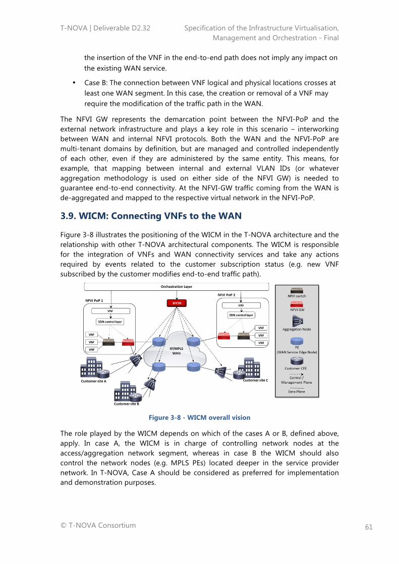
T-NOVA | Deliverable D2.32 Specification of the Infrastructure Virtualisation, Management and Orchestration - Final
© T-NOVA Consortium
61
the insertion of the VNF in the end-to-end path does not imply any impact on the existing WAN service.
• Case B: The connection between VNF logical and physical locations crosses at least one WAN segment. In this case, the creation or removal of a VNF may require the modification of the traffic path in the WAN.
The NFVI GW represents the demarcation point between the NFVI-PoP and the external network infrastructure and plays a key role in this scenario – interworking between WAN and internal NFVI protocols. Both the WAN and the NFVI-PoP are multi-tenant domains by definition, but are managed and controlled independently of each other, even if they are administered by the same entity. This means, for example, that mapping between internal and external VLAN IDs (or whatever aggregation methodology is used on either side of the NFVI GW) is needed to guarantee end-to-end connectivity. At the NFVI-GW traffic coming from the WAN is de-aggregated and mapped to the respective virtual network in the NFVI-PoP.
3.9. WICM: Connecting VNFs to the WAN
Figure 3-8 illustrates the positioning of the WICM in the T-NOVA architecture and the relationship with other T-NOVA architectural components. The WICM is responsible for the integration of VNFs and WAN connectivity services and take any actions required by events related to the customer subscription status (e.g. new VNF subscribed by the customer modifies end-to-end traffic path).
Figure 3-8 - WICM overall vision
The role played by the WICM depends on which of the cases A or B, defined above, apply. In case A, the WICM is in charge of controlling network nodes at the access/aggregation network segment, whereas in case B the WICM should also control the network nodes (e.g. MPLS PEs) located deeper in the service provider network. In T-NOVA, Case A should be considered as preferred for implementation and demonstration purposes.
T-NOVA | Deliverable D2.32 Specification of the Infrastructure Virtualisation, Management and Orchestration - Final
© T-NOVA Consortium
62
3.9.1.1. SDN-enabled Network Elements
Today’s WANs are becoming more complex and the introduction of SDN aligned approaches holds great potential for managing and monitoring network devices and the traffic which flows over them. The benefits are mainly related to automated network provisioning and to the flexibility in link deployment between different data centres.
From a T-NOVA perspective, the WICM has responsibility for controlling and monitoring the physical network devices which are SDN-enabled, with the purpose of providing WAN connectivity between different NFVI-PoPs while considering both SLAs required by VNFs and efficient management of cloud infrastructure resources. The WICM and VIM Network Control modules will need to be coordinated by the Orchestrator in an appropriate manner, in order to setup VLANs among different virtual and physical SDN-enabled devices.
Although for the intra-DC networking the deployment of SDN technologies is becoming more common place, the adoption of SDN at the transport level and especially at Layer 0 to 1, is still very much in its infancy [19] [20]. When considering the transport layers we encompass technologies at layer 0 (DWDM, photonics) and layer 1 (SONET/SDH and OTN). A key reason for the delay in SDN adoption in the transport network is the on-going transition from the analog to digital domain. The mechanisms for dealing with analog attributes in optical networks are vendor specific, and it is not possible for a generic controller to deal with the current myriad of vendor specific implementations. Nor is it possible for network operators to remove all of their transport equipment from their networks and replace it with a standardised optical hardware based around open standards. However, at higher layers (i.e. WAN) the adoption path is potentially more expeditious. Companies like Google and the Carrier Ethernet (MEF) and cloud business units of network operators have already adopted SDN solutions for their WANs [21].
For the purpose of the T-NOVA proof-of-concept demonstration the WICM development of SDN compatible devices is out of scope as it is not part of the objectives of the project which are mostly focusing on the NFVI-PoP network management and control. However, at an architectural level it is thoroughly supported to ensure appropriate future proofing.
3.9.1.2. Legacy Network Elements
Managing and monitoring legacy network domains is a well understood and mature capability. A variety of standardised and proprietary frameworks have been proposed and implemented in the form of commercial and open source solutions.
The WICM is the T-NOVA architectural component in charge of enabling interoperability between NFVI-PoP and WAN connectivity services, including legacy service models such as or MPLS-based IP-VPN, or Carrier Ethernet E-LAN, E-Line.
As noted above, the integration of NFVI-PoPs in legacy WAN services can be more or less complex, depending on factors such as the logical location of the NFVI-PoP,
T-NOVA | Deliverable D2.32 Specification of the Infrastructure Virtualisation, Management and Orchestration - Final
© T-NOVA Consortium
63
namely whether the connection between logical and physical locations of the VNFs crosses any WAN segment.
As outlined in the SOTA review (section 4.3) the standard method for allowing network overlays over legacy network domain is the exploitation of L2 to L3 tunnelling mechanisms. Those mechanisms introduce the use of tunnelling protocols that allow the management aspects of each tunnel on an end-to-end basis. The most interesting tunnelling protocols, from a T-NOVA architecture perspective, are VxLAN, and Generic Routing Encapsulation (GRE). In short these protocols allow the interconnection of NFVI-PoPs over L3 legacy network by encapsulating the NFVI network traffic (actually DC traffic) end-to-end. They require the setup of an end-point for each connected DC, which is responsible for encapsulation and decapsulation of packets.
At a WAN level the architecture design of T-NOVA supports any type of legacy WAN technology (i.e. MPLS, Optical, Carrier Ethernet etc.) or SDN compatible, provided that the appropriate interfaces are developed. In this context, and for the sake of demonstrating the UC as discussed in D2.1, T-NOVA will exploit an IP/MPLS transport network and provide a simple implementation of WICM in order to support provisioning of vNETs in an end-to-end manner.
From a monitoring perspective, there are a number of frameworks ranging from passive to active and hybrid that allow the monitoring of legacy networks [22] [23]. T-NOVA will employ such mechanisms in order to monitor adequately the status of the network and more importantly the status and resource usage of the established tunnels. Monitoring of the transport network resources will also be part of the considered WICM functionalities that will be implemented. Moreover, the monitoring information will be conveyed to the NFVO as an input in the mapping and path computation mechanism. Historical monitoring data collection will also be collected to facilitate tracking of SLA breaches.
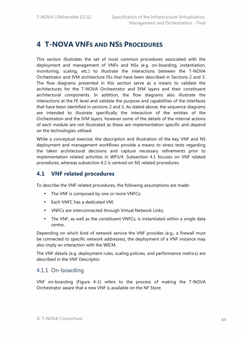
T-NOVA | Deliverable D2.32 Specification of the Infrastructure Virtualisation, Management and Orchestration - Final
© T-NOVA Consortium
64
4 T-NOVA VNFS AND NSS PROCEDURES
This section illustrates the set of most common procedures associated with the deployment and management of VNFs and NSs (e.g. on-boarding, instantiation, monitoring, scaling, etc.) to illustrate the interactions between the T-NOVA Orchestrator and IVM architecture FEs that have been described in Sections 2 and 3. The flow diagrams presented in this section serve as a means to validate the architectures for the T-NOVA Orchestrator and IVM layers and their constituent architectural components. In addition, the flow diagrams also illustrate the interactions at the FE level and validate the purpose and capabilities of the interfaces that have been identified in sections 2 and 3. As stated above, the sequence diagrams are intended to illustrate specifically the interaction of the entities of the Orchestration and the IVM layers, however some of the details of the internal actions of each module are not illustrated as these are implementation specific and depend on the technologies utilised.
While a conceptual exercise, the description and illustration of the key VNF and NS deployment and management workflows provide a means to stress tests regarding the taken architectural decisions and capture necessary refinements prior to implementation related activities in WP3/4. Subsection 4.1 focuses on VNF related procedures, whereas subsection 4.2 is centred on NS related procedures.
4.1 VNF related procedures
To describe the VNF related procedures, the following assumptions are made:
• The VNF is composed by one or more VNFCs;
• Each VNFC has a dedicated VM;
• VNFCs are interconnected through Virtual Network Links;
• The VNF, as well as the constituent VNFCs, is instantiated within a single data centre.
Depending on which kind of network service the VNF provides (e.g., a firewall must be connected to specific network addresses), the deployment of a VNF instance may also imply an interaction with the WICM.
The VNF details (e.g. deployment rules, scaling policies, and performance metrics) are described in the VNF Descriptor.
4.1.1 On-boarding
VNF on-boarding (Figure 4-1) refers to the process of making the T-NOVA Orchestrator aware that a new VNF is available on the NF Store.
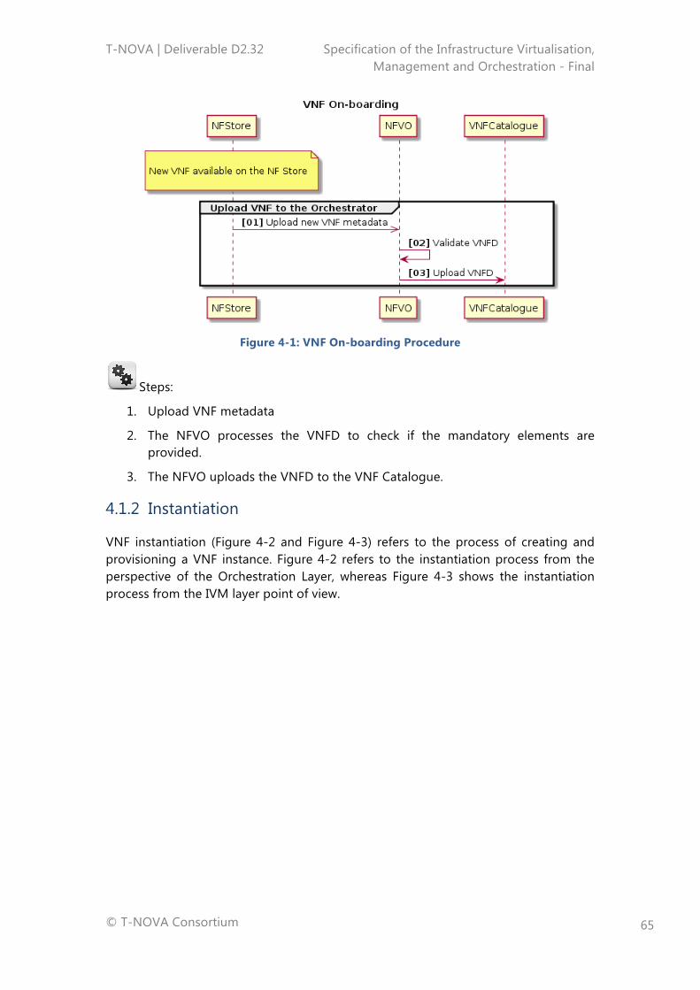
T-NOVA | Deliverable D2.32 Specification of the Infrastructure Virtualisation, Management and Orchestration - Final
© T-NOVA Consortium
65
Figure 4-1: VNF On-boarding Procedure
Steps:
1. Upload VNF metadata
2. The NFVO processes the VNFD to check if the mandatory elements are provided.
3. The NFVO uploads the VNFD to the VNF Catalogue.
4.1.2 Instantiation
VNF instantiation (Figure 4-2 and Figure 4-3) refers to the process of creating and provisioning a VNF instance. Figure 4-2 refers to the instantiation process from the perspective of the Orchestration Layer, whereas Figure 4-3 shows the instantiation process from the IVM layer point of view.
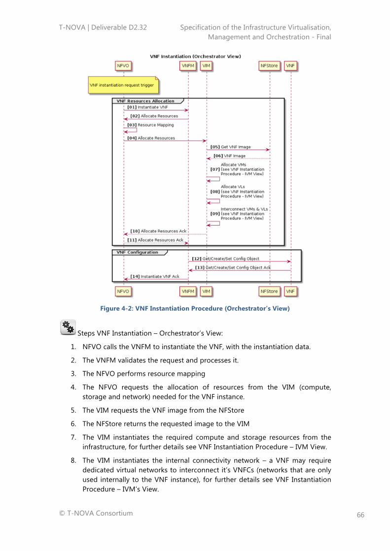
T-NOVA | Deliverable D2.32 Specification of the Infrastructure Virtualisation, Management and Orchestration - Final
© T-NOVA Consortium
66
Figure 4-2: VNF Instantiation Procedure (Orchestrator’s View)
Steps VNF Instantiation – Orchestrator’s View:
1. NFVO calls the VNFM to instantiate the VNF, with the instantiation data.
2. The VNFM validates the request and processes it.
3. The NFVO performs resource mapping
4. The NFVO requests the allocation of resources from the VIM (compute, storage and network) needed for the VNF instance.
5. The VIM requests the VNF image from the NFStore
6. The NFStore returns the requested image to the VIM
7. The VIM instantiates the required compute and storage resources from the infrastructure, for further details see VNF Instantiation Procedure – IVM View.
8. The VIM instantiates the internal connectivity network – a VNF may require dedicated virtual networks to interconnect it’s VNFCs (networks that are only used internally to the VNF instance), for further details see VNF Instantiation Procedure – IVM’s View.
T-NOVA | Deliverable D2.32 Specification of the Infrastructure Virtualisation, Management and Orchestration - Final
© T-NOVA Consortium
67
9. The VIM interconnects the instantiated internal connectivity network with the VNFCs, for further details see VNF Instantiation Procedure – IVM View.
10. Acknowledgement of completion of resource allocation back to NFVO.
11. The NFVO acknowledges the completion of the resource allocation back to VNFM, returning appropriate configuration information.
12. After the VNF is instantiated, the VNFM configures the VNF with any VNF specific lifecycle parameters (deployment parameters).
13. The VNF sends an acknowledgement to the VNFM that the configuration process is completed.
14. The VNFM acknowledges the completion of the VNF instantiation back to the NFVO.
The diagram corresponding to steps 8-10 is indicated below.
Figure 4-3: VNF Instantiation Procedure (IVM’s View)
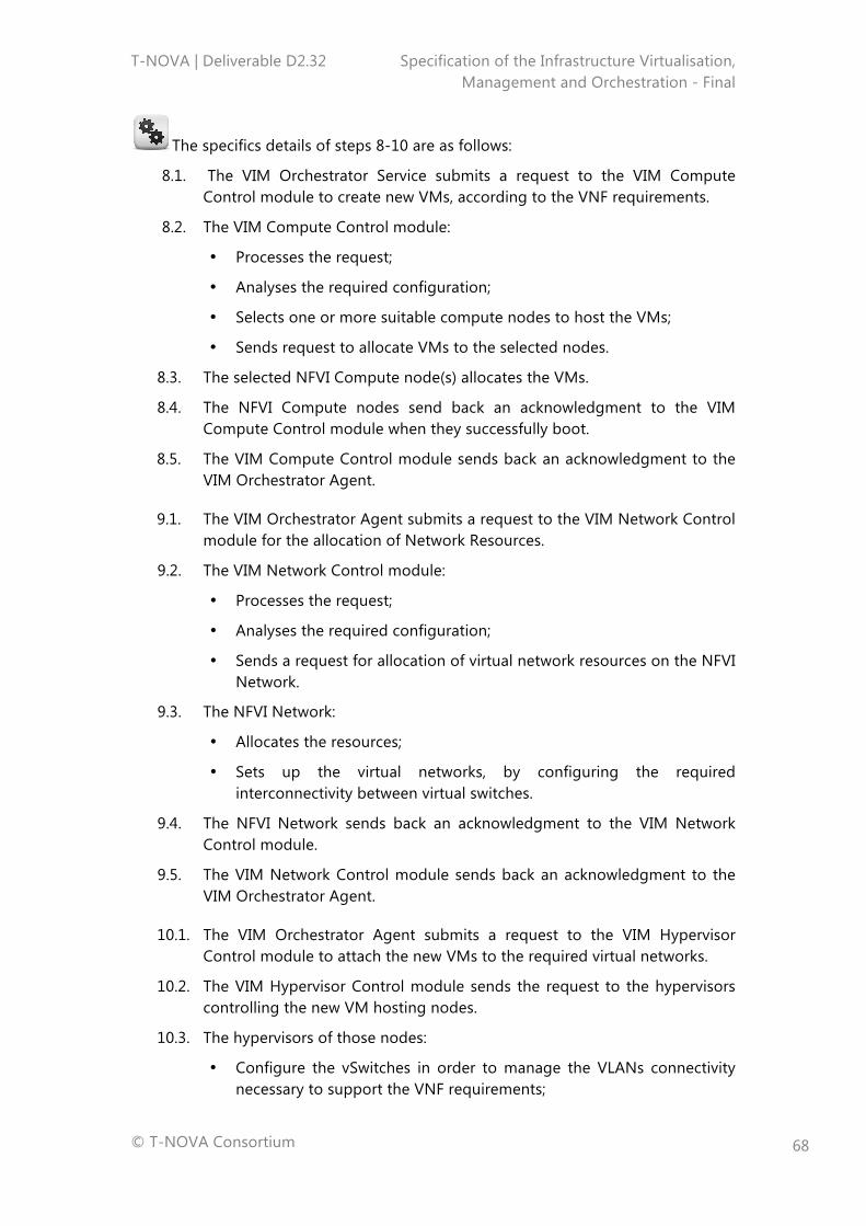
T-NOVA | Deliverable D2.32 Specification of the Infrastructure Virtualisation, Management and Orchestration - Final
© T-NOVA Consortium
68
The specifics details of steps 8-10 are as follows:
8.1. The VIM Orchestrator Service submits a request to the VIM Compute Control module to create new VMs, according to the VNF requirements.
8.2. The VIM Compute Control module:
• Processes the request;
• Analyses the required configuration;
• Selects one or more suitable compute nodes to host the VMs;
• Sends request to allocate VMs to the selected nodes.
8.3. The selected NFVI Compute node(s) allocates the VMs.
8.4. The NFVI Compute nodes send back an acknowledgment to the VIM Compute Control module when they successfully boot.
8.5. The VIM Compute Control module sends back an acknowledgment to the VIM Orchestrator Agent.
9.1. The VIM Orchestrator Agent submits a request to the VIM Network Control module for the allocation of Network Resources.
9.2. The VIM Network Control module:
• Processes the request;
• Analyses the required configuration;
• Sends a request for allocation of virtual network resources on the NFVI Network.
9.3. The NFVI Network:
• Allocates the resources;
• Sets up the virtual networks, by configuring the required interconnectivity between virtual switches.
9.4. The NFVI Network sends back an acknowledgment to the VIM Network Control module.
9.5. The VIM Network Control module sends back an acknowledgment to the VIM Orchestrator Agent.
10.1. The VIM Orchestrator Agent submits a request to the VIM Hypervisor Control module to attach the new VMs to the required virtual networks.
10.2. The VIM Hypervisor Control module sends the request to the hypervisors controlling the new VM hosting nodes.
10.3. The hypervisors of those nodes:
• Configure the vSwitches in order to manage the VLANs connectivity necessary to support the VNF requirements;
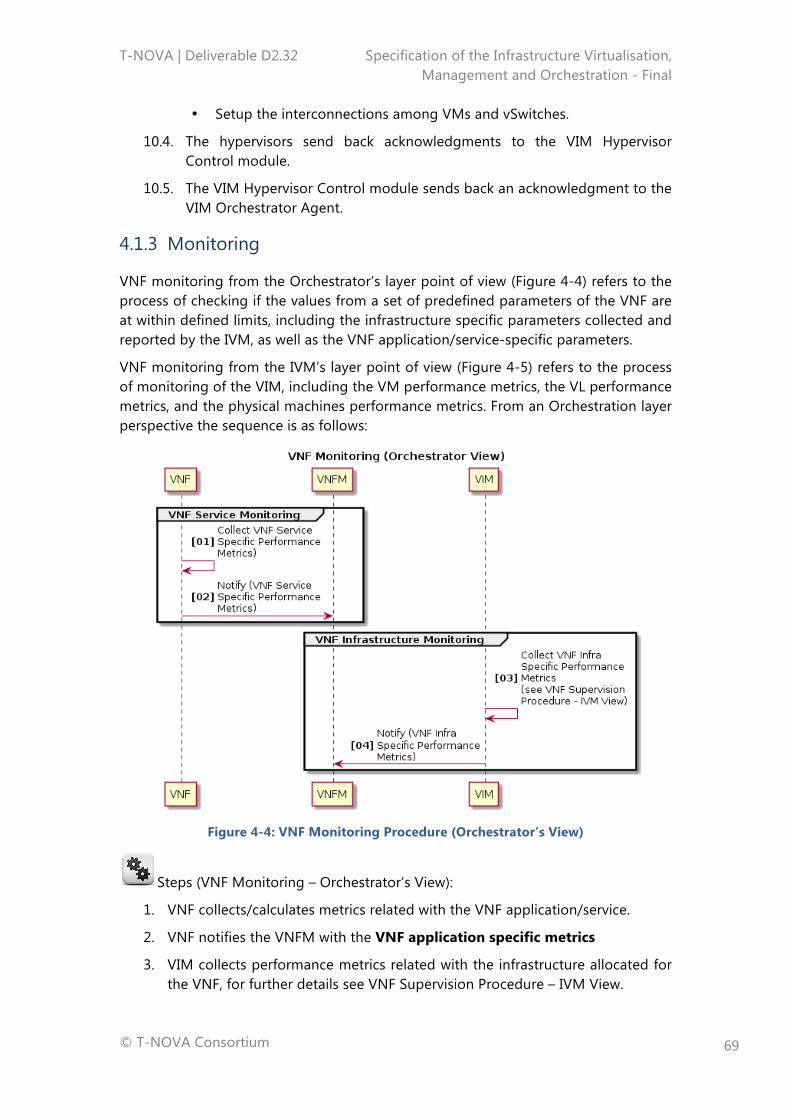
T-NOVA | Deliverable D2.32 Specification of the Infrastructure Virtualisation, Management and Orchestration - Final
© T-NOVA Consortium
69
• Setup the interconnections among VMs and vSwitches.
10.4. The hypervisors send back acknowledgments to the VIM Hypervisor Control module.
10.5. The VIM Hypervisor Control module sends back an acknowledgment to the VIM Orchestrator Agent.
4.1.3 Monitoring
VNF monitoring from the Orchestrator’s layer point of view (Figure 4-4) refers to the process of checking if the values from a set of predefined parameters of the VNF are at within defined limits, including the infrastructure specific parameters collected and reported by the IVM, as well as the VNF application/service-specific parameters.
VNF monitoring from the IVM’s layer point of view (Figure 4-5) refers to the process of monitoring of the VIM, including the VM performance metrics, the VL performance metrics, and the physical machines performance metrics. From an Orchestration layer perspective the sequence is as follows:
Figure 4-4: VNF Monitoring Procedure (Orchestrator’s View)
Steps (VNF Monitoring – Orchestrator’s View):
1. VNF collects/calculates metrics related with the VNF application/service.
2. VNF notifies the VNFM with the VNF application specific metrics
3. VIM collects performance metrics related with the infrastructure allocated for the VNF, for further details see VNF Supervision Procedure – IVM View.
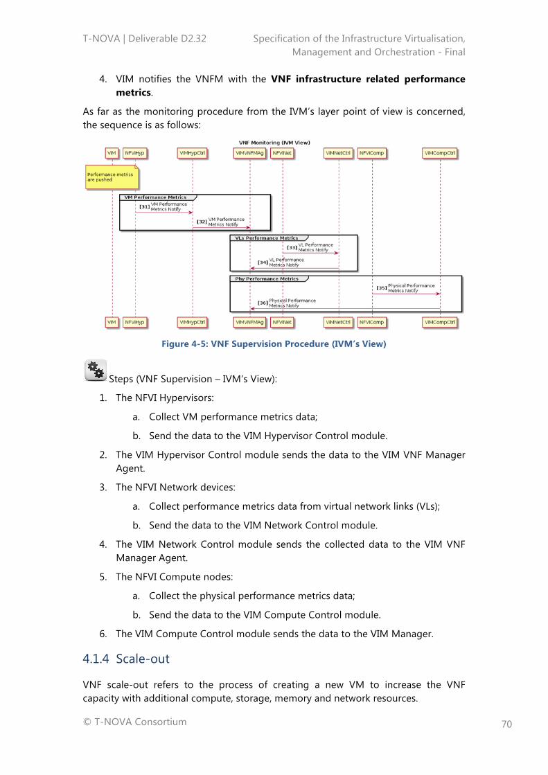
T-NOVA | Deliverable D2.32 Specification of the Infrastructure Virtualisation, Management and Orchestration - Final
© T-NOVA Consortium
70
4. VIM notifies the VNFM with the VNF infrastructure related performance metrics.
As far as the monitoring procedure from the IVM’s layer point of view is concerned, the sequence is as follows:
Figure 4-5: VNF Supervision Procedure (IVM’s View)
Steps (VNF Supervision – IVM’s View):
1. The NFVI Hypervisors:
a. Collect VM performance metrics data;
b. Send the data to the VIM Hypervisor Control module.
2. The VIM Hypervisor Control module sends the data to the VIM VNF Manager Agent.
3. The NFVI Network devices:
a. Collect performance metrics data from virtual network links (VLs);
b. Send the data to the VIM Network Control module.
4. The VIM Network Control module sends the collected data to the VIM VNF Manager Agent.
5. The NFVI Compute nodes:
a. Collect the physical performance metrics data;
b. Send the data to the VIM Compute Control module.
6. The VIM Compute Control module sends the data to the VIM Manager.
4.1.4 Scale-out
VNF scale-out refers to the process of creating a new VM to increase the VNF capacity with additional compute, storage, memory and network resources.
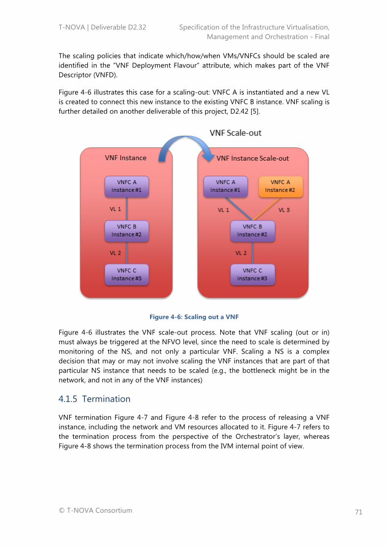
T-NOVA | Deliverable D2.32 Specification of the Infrastructure Virtualisation, Management and Orchestration - Final
© T-NOVA Consortium
71
The scaling policies that indicate which/how/when VMs/VNFCs should be scaled are identified in the ”VNF Deployment Flavour” attribute, which makes part of the VNF Descriptor (VNFD).
Figure 4-6 illustrates this case for a scaling-out: VNFC A is instantiated and a new VL is created to connect this new instance to the existing VNFC B instance. VNF scaling is further detailed on another deliverable of this project, D2.42 [5].
Figure 4-6: Scaling out a VNF
Figure 4-6 illustrates the VNF scale-out process. Note that VNF scaling (out or in) must always be triggered at the NFVO level, since the need to scale is determined by monitoring of the NS, and not only a particular VNF. Scaling a NS is a complex decision that may or may not involve scaling the VNF instances that are part of that particular NS instance that needs to be scaled (e.g., the bottleneck might be in the network, and not in any of the VNF instances)
4.1.5 Termination
VNF termination Figure 4-7 and Figure 4-8 refer to the process of releasing a VNF instance, including the network and VM resources allocated to it. Figure 4-7 refers to the termination process from the perspective of the Orchestrator’s layer, whereas Figure 4-8 shows the termination process from the IVM internal point of view.
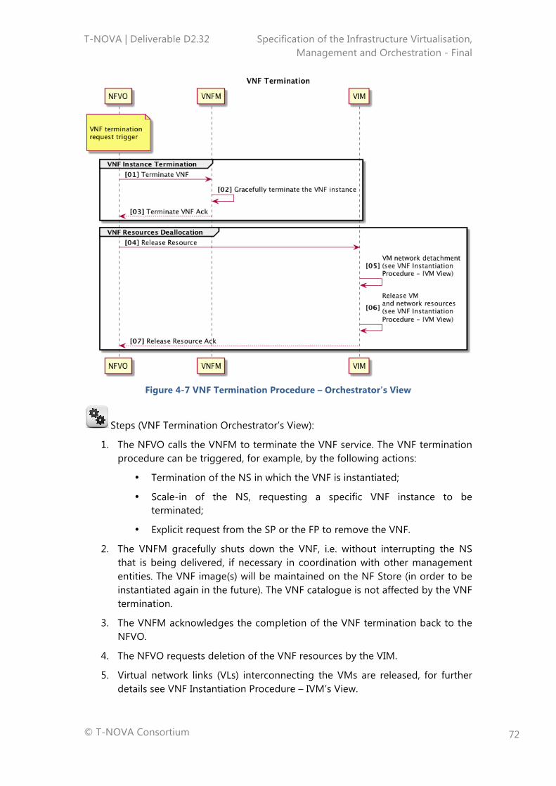
T-NOVA | Deliverable D2.32 Specification of the Infrastructure Virtualisation, Management and Orchestration - Final
© T-NOVA Consortium
72
Figure 4-7 VNF Termination Procedure – Orchestrator’s View
Steps (VNF Termination Orchestrator’s View):
1. The NFVO calls the VNFM to terminate the VNF service. The VNF termination procedure can be triggered, for example, by the following actions:
• Termination of the NS in which the VNF is instantiated;
• Scale-in of the NS, requesting a specific VNF instance to be terminated;
• Explicit request from the SP or the FP to remove the VNF.
2. The VNFM gracefully shuts down the VNF, i.e. without interrupting the NS that is being delivered, if necessary in coordination with other management entities. The VNF image(s) will be maintained on the NF Store (in order to be instantiated again in the future). The VNF catalogue is not affected by the VNF termination.
3. The VNFM acknowledges the completion of the VNF termination back to the NFVO.
4. The NFVO requests deletion of the VNF resources by the VIM.
5. Virtual network links (VLs) interconnecting the VMs are released, for further details see VNF Instantiation Procedure – IVM’s View.
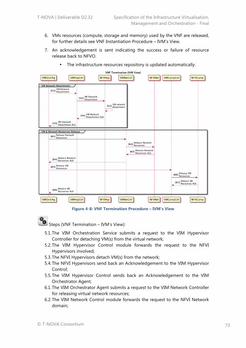
T-NOVA | Deliverable D2.32 Specification of the Infrastructure Virtualisation, Management and Orchestration - Final
© T-NOVA Consortium
73
6. VMs resources (compute, storage and memory) used by the VNF are released, for further details see VNF Instantiation Procedure – IVM’s View.
7. An acknowledgement is sent indicating the success or failure of resource release back to NFVO.
• The infrastructure resources repository is updated automatically.
Figure 4-8: VNF Termination Procedure – IVM’s View
Steps (VNF Termination – IVM’s View):
5.1. The VIM Orchestration Service submits a request to the VIM Hypervisor Controller for detaching VM(s) from the virtual network;
5.2. The VIM Hypervisor Control module forwards the request to the NFVI Hypervisors involved;
5.3. The NFVI Hypervisors detach VM(s) from the network; 5.4. The NFVI Hypervisors send back an Acknowledgement to the VIM Hypervisor
Control; 5.5. The VIM Hypervisor Control sends back an Acknowledgement to the VIM
Orchestrator Agent; 6.1. The VIM Orchestrator Agent submits a request to the VIM Network Controller
for releasing virtual network resources; 6.2. The VIM Network Control module forwards the request to the NFVI Network
domain;
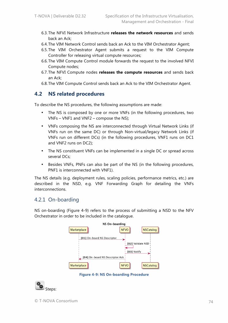
T-NOVA | Deliverable D2.32 Specification of the Infrastructure Virtualisation, Management and Orchestration - Final
© T-NOVA Consortium
74
6.3. The NFVI Network Infrastructure releases the network resources and sends back an Ack;
6.4. The VIM Network Control sends back an Ack to the VIM Orchestrator Agent; 6.5. The VIM Orchestrator Agent submits a request to the VIM Compute
Controller for releasing virtual compute resources; 6.6. The VIM Compute Control module forwards the request to the involved NFVI
Compute nodes; 6.7. The NFVI Compute nodes releases the compute resources and sends back
an Ack; 6.8. The VIM Compute Control sends back an Ack to the VIM Orchestrator Agent.
4.2 NS related procedures
To describe the NS procedures, the following assumptions are made:
• The NS is composed by one or more VNFs (in the following procedures, two VNFs – VNF1 and VNF2 – compose the NS);
• VNFs composing the NS are interconnected through Virtual Network Links (if VNFs run on the same DC) or through Non-virtual/legacy Network Links (if VNFs run on different DCs) (in the following procedures, VNF1 runs on DC1 and VNF2 runs on DC2);
• The NS constituent VNFs can be implemented in a single DC or spread across several DCs;
• Besides VNFs, PNFs can also be part of the NS (in the following procedures, PNF1 is interconnected with VNF1).
The NS details (e.g. deployment rules, scaling policies, performance metrics, etc.) are described in the NSD, e.g. VNF Forwarding Graph for detailing the VNFs interconnections.
4.2.1 On-boarding
NS on-boarding (Figure 4-9) refers to the process of submitting a NSD to the NFV Orchestrator in order to be included in the catalogue.
Figure 4-9: NS On-boarding Procedure
Steps:
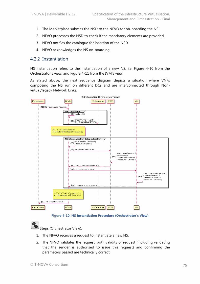
T-NOVA | Deliverable D2.32 Specification of the Infrastructure Virtualisation, Management and Orchestration - Final
© T-NOVA Consortium
75
1. The Marketplace submits the NSD to the NFVO for on-boarding the NS.
2. NFVO processes the NSD to check if the mandatory elements are provided.
3. NFVO notifies the catalogue for insertion of the NSD.
4. NFVO acknowledges the NS on-boarding.
4.2.2 Instantiation
NS instantiation refers to the instantiation of a new NS, i.e. Figure 4-10 from the Orchestrator’s view, and Figure 4-11 from the IVM’s view.
As stated above, the next sequence diagram depicts a situation where VNFs composing the NS run on different DCs and are interconnected through Non-virtual/legacy Network Links.
Figure 4-10: NS Instantiation Procedure (Orchestrator’s View)
Steps (Orchestrator View):
1. The NFVO receives a request to instantiate a new NS.
2. The NFVO validates the request, both validity of request (including validating that the sender is authorised to issue this request) and confirming the parameters passed are technically correct.
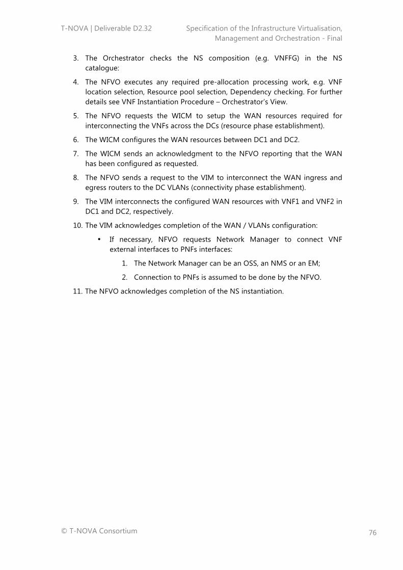
T-NOVA | Deliverable D2.32 Specification of the Infrastructure Virtualisation, Management and Orchestration - Final
© T-NOVA Consortium
76
3. The Orchestrator checks the NS composition (e.g. VNFFG) in the NS catalogue:
4. The NFVO executes any required pre-allocation processing work, e.g. VNF location selection, Resource pool selection, Dependency checking. For further details see VNF Instantiation Procedure – Orchestrator’s View.
5. The NFVO requests the WICM to setup the WAN resources required for interconnecting the VNFs across the DCs (resource phase establishment).
6. The WICM configures the WAN resources between DC1 and DC2.
7. The WICM sends an acknowledgment to the NFVO reporting that the WAN has been configured as requested.
8. The NFVO sends a request to the VIM to interconnect the WAN ingress and egress routers to the DC VLANs (connectivity phase establishment).
9. The VIM interconnects the configured WAN resources with VNF1 and VNF2 in DC1 and DC2, respectively.
10. The VIM acknowledges completion of the WAN / VLANs configuration:
• If necessary, NFVO requests Network Manager to connect VNF external interfaces to PNFs interfaces:
1. The Network Manager can be an OSS, an NMS or an EM;
2. Connection to PNFs is assumed to be done by the NFVO.
11. The NFVO acknowledges completion of the NS instantiation.
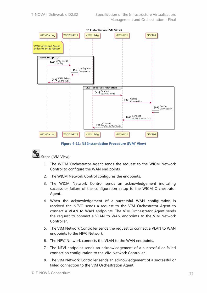
T-NOVA | Deliverable D2.32 Specification of the Infrastructure Virtualisation, Management and Orchestration - Final
© T-NOVA Consortium
77
Figure 4-11: NS Instantiation Procedure (IVM’ View)
Steps (IVM View):
1. The WICM Orchestrator Agent sends the request to the WICM Network Control to configure the WAN end points.
2. The WICM Network Control configures the endpoints.
3. The WICM Network Control sends an acknowledgement indicating success or failure of the configuration setup to the WICM Orchestrator Agent.
4. When the acknowledgement of a successful WAN configuration is received the NFVO sends a request to the VIM Orchestrator Agent to connect a VLAN to WAN endpoints. The VIM Orchestrator Agent sends the request to connect a VLAN to WAN endpoints to the VIM Network Controller.
5. The VIM Network Controller sends the request to connect a VLAN to WAN endpoints to the NFVI Network.
6. The NFVI Network connects the VLAN to the WAN endpoints.
7. The NFVI endpoint sends an acknowledgement of a successful or failed connection configuration to the VIM Network Controller.
8. The VIM Network Controller sends an acknowledgement of a successful or failed connection to the VIM Orchestration Agent.
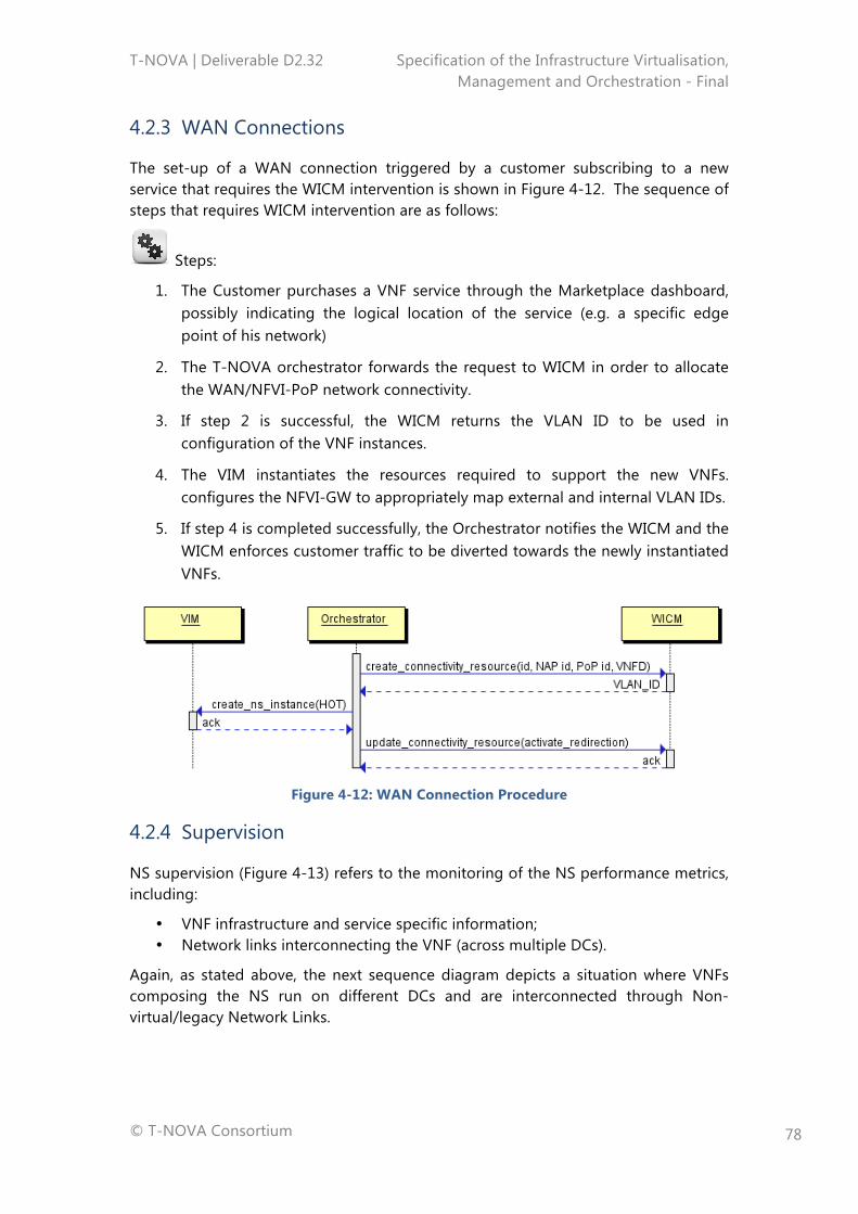
T-NOVA | Deliverable D2.32 Specification of the Infrastructure Virtualisation, Management and Orchestration - Final
© T-NOVA Consortium
78
4.2.3 WAN Connections
The set-up of a WAN connection triggered by a customer subscribing to a new service that requires the WICM intervention is shown in Figure 4-12. The sequence of steps that requires WICM intervention are as follows:
Steps:
1. The Customer purchases a VNF service through the Marketplace dashboard, possibly indicating the logical location of the service (e.g. a specific edge point of his network)
2. The T-NOVA orchestrator forwards the request to WICM in order to allocate the WAN/NFVI-PoP network connectivity.
3. If step 2 is successful, the WICM returns the VLAN ID to be used in configuration of the VNF instances.
4. The VIM instantiates the resources required to support the new VNFs. configures the NFVI-GW to appropriately map external and internal VLAN IDs.
5. If step 4 is completed successfully, the Orchestrator notifies the WICM and the WICM enforces customer traffic to be diverted towards the newly instantiated VNFs.
Figure 4-12: WAN Connection Procedure
4.2.4 Supervision
NS supervision (Figure 4-13) refers to the monitoring of the NS performance metrics, including:
• VNF infrastructure and service specific information; • Network links interconnecting the VNF (across multiple DCs).
Again, as stated above, the next sequence diagram depicts a situation where VNFs composing the NS run on different DCs and are interconnected through Non-virtual/legacy Network Links.
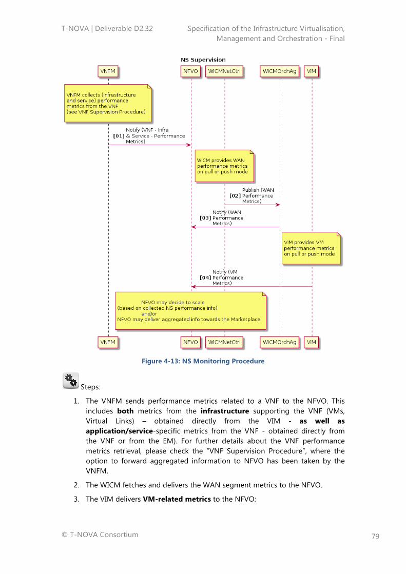
T-NOVA | Deliverable D2.32 Specification of the Infrastructure Virtualisation, Management and Orchestration - Final
© T-NOVA Consortium
79
Figure 4-13: NS Monitoring Procedure
Steps:
1. The VNFM sends performance metrics related to a VNF to the NFVO. This includes both metrics from the infrastructure supporting the VNF (VMs, Virtual Links) – obtained directly from the VIM - as well as application/service-specific metrics from the VNF - obtained directly from the VNF or from the EM). For further details about the VNF performance metrics retrieval, please check the “VNF Supervision Procedure”, where the option to forward aggregated information to NFVO has been taken by the VNFM.
2. The WICM fetches and delivers the WAN segment metrics to the NFVO.
3. The VIM delivers VM-related metrics to the NFVO:
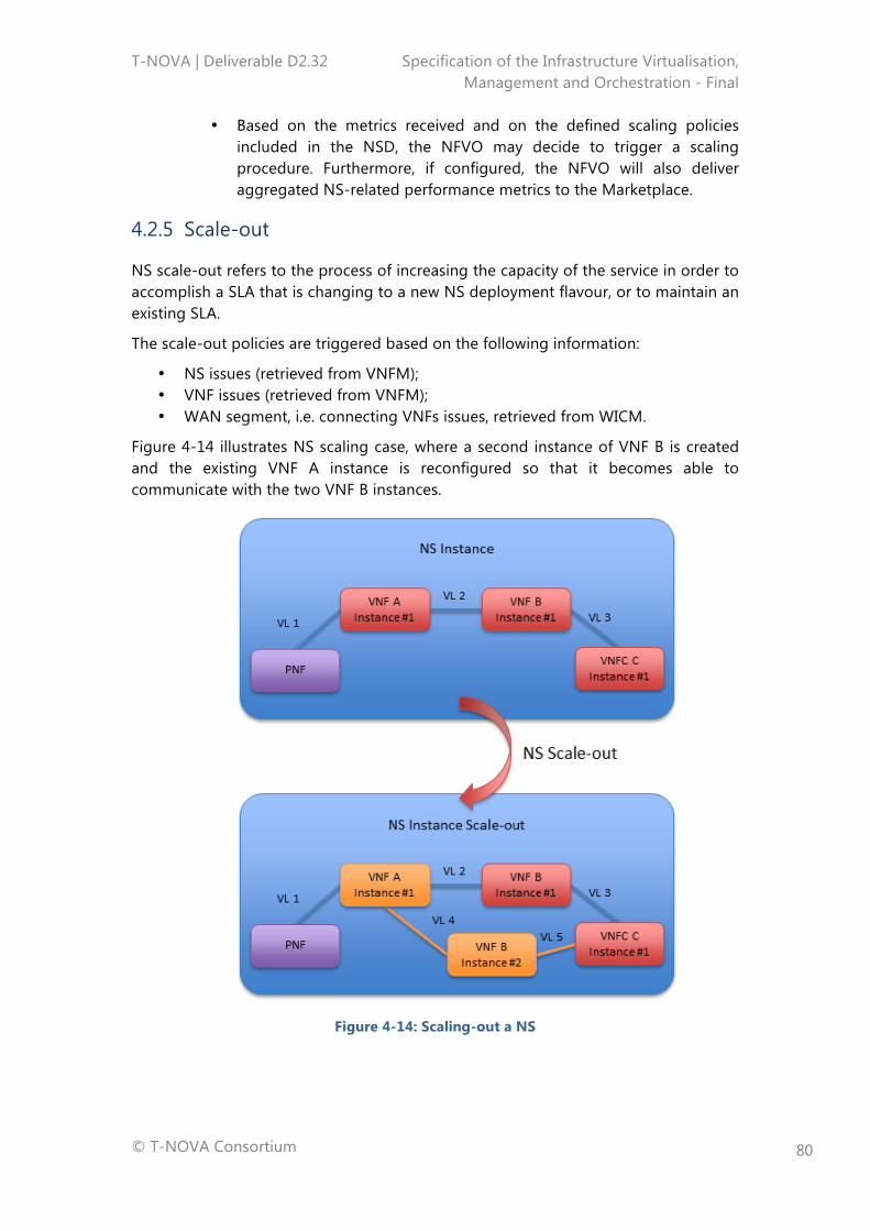
T-NOVA | Deliverable D2.32 Specification of the Infrastructure Virtualisation, Management and Orchestration - Final
© T-NOVA Consortium
80
• Based on the metrics received and on the defined scaling policies included in the NSD, the NFVO may decide to trigger a scaling procedure. Furthermore, if configured, the NFVO will also deliver aggregated NS-related performance metrics to the Marketplace.
4.2.5 Scale-out
NS scale-out refers to the process of increasing the capacity of the service in order to accomplish a SLA that is changing to a new NS deployment flavour, or to maintain an existing SLA.
The scale-out policies are triggered based on the following information:
• NS issues (retrieved from VNFM); • VNF issues (retrieved from VNFM); • WAN segment, i.e. connecting VNFs issues, retrieved from WICM.
Figure 4-14 illustrates NS scaling case, where a second instance of VNF B is created and the existing VNF A instance is reconfigured so that it becomes able to communicate with the two VNF B instances.
Figure 4-14: Scaling-out a NS
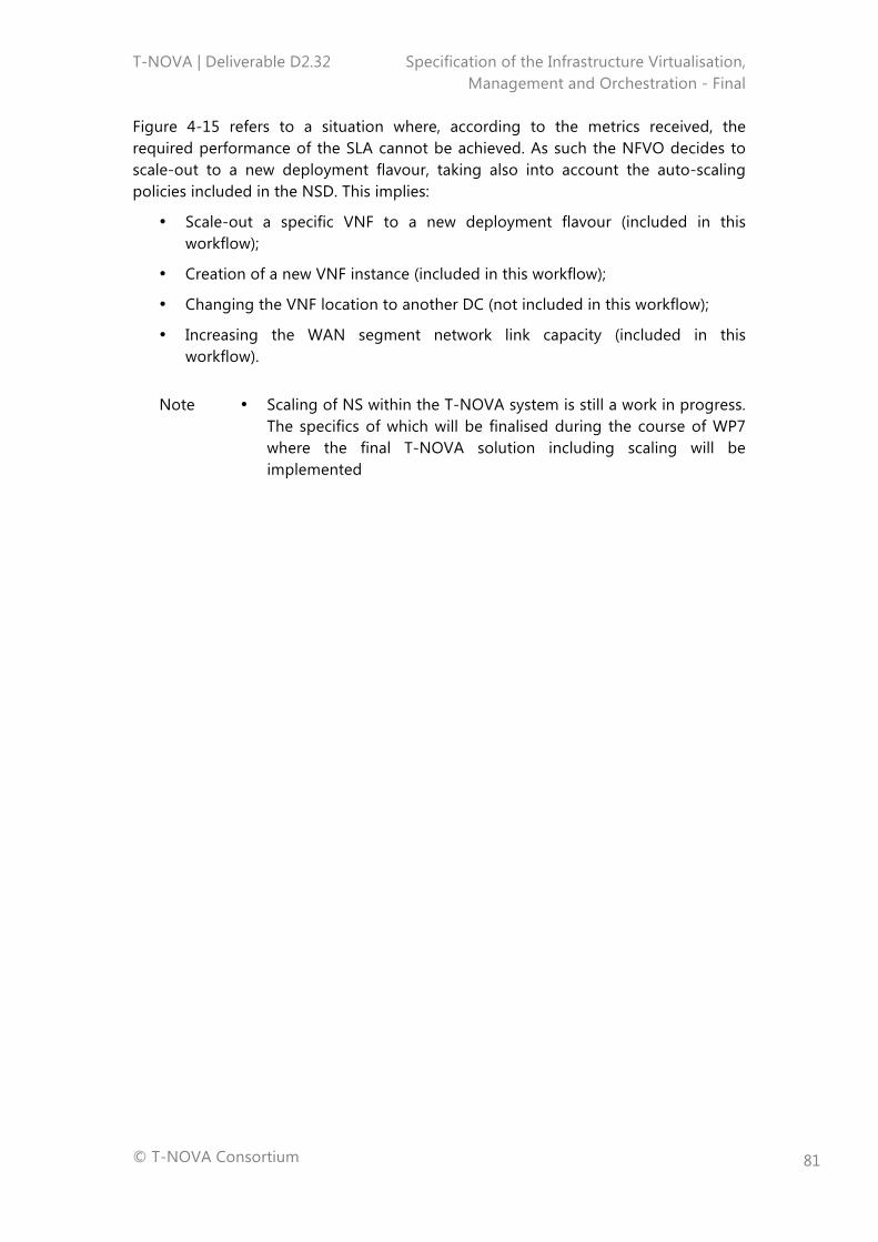
T-NOVA | Deliverable D2.32 Specification of the Infrastructure Virtualisation, Management and Orchestration - Final
© T-NOVA Consortium
81
Figure 4-15 refers to a situation where, according to the metrics received, the required performance of the SLA cannot be achieved. As such the NFVO decides to scale-out to a new deployment flavour, taking also into account the auto-scaling policies included in the NSD. This implies:
• Scale-out a specific VNF to a new deployment flavour (included in this workflow);
• Creation of a new VNF instance (included in this workflow);
• Changing the VNF location to another DC (not included in this workflow);
• Increasing the WAN segment network link capacity (included in this workflow).
Note • Scaling of NS within the T-NOVA system is still a work in progress. The specifics of which will be finalised during the course of WP7 where the final T-NOVA solution including scaling will be implemented
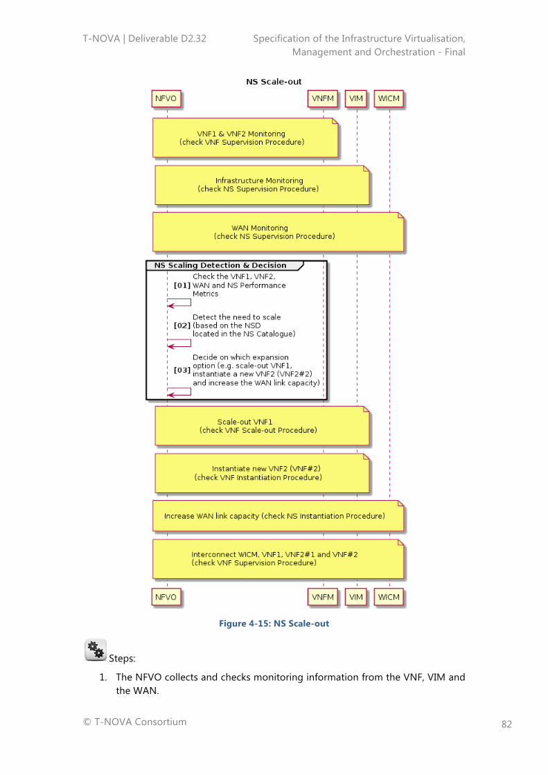
T-NOVA | Deliverable D2.32 Specification of the Infrastructure Virtualisation, Management and Orchestration - Final
© T-NOVA Consortium
82
Figure 4-15: NS Scale-out
Steps:
1. The NFVO collects and checks monitoring information from the VNF, VIM and the WAN.
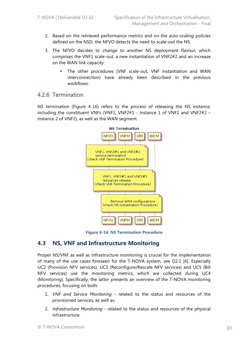
T-NOVA | Deliverable D2.32 Specification of the Infrastructure Virtualisation, Management and Orchestration - Final
© T-NOVA Consortium
83
2. Based on the retrieved performance metrics and on the auto-scaling policies defined on the NSD, the NFVO detects the need to scale-out the NS.
3. The NFVO decides to change to another NS deployment flavour, which comprises the VNF1 scale-out, a new instantiation of VNF2#2 and an increase on the WAN link capacity:
• The other procedures (VNF scale-out, VNF instantiation and WAN interconnection) have already been described in the previous workflows.
4.2.6 Termination
NS termination (Figure 4-16) refers to the process of releasing the NS instance, including the constituent VNFs (VNF1, VNF2#1 - instance 1 of VNF2 and VNF2#2 – instance 2 of VNF2), as well as the WAN segment.
Figure 4-16: NS Termination Procedure
4.3 NS, VNF and Infrastructure Monitoring
Proper NS/VNF as well as infrastructure monitoring is crucial for the implementation of many of the use cases foreseen for the T-NOVA system, see D2.1 [6]. Especially UC2 (Provision NFV services), UC3 (Reconfigure/Rescale NFV services) and UC5 (Bill NFV services) use the monitoring metrics, which are collected during UC4 (Monitoring). Specifically, the latter presents an overview of the T-NOVA monitoring procedures, focusing on both:
1. VNF and Service Monitoring - related to the status and resources of the provisioned services, as well as,
2. Infrastructure Monitoring - related to the status and resources of the physical infrastructure.
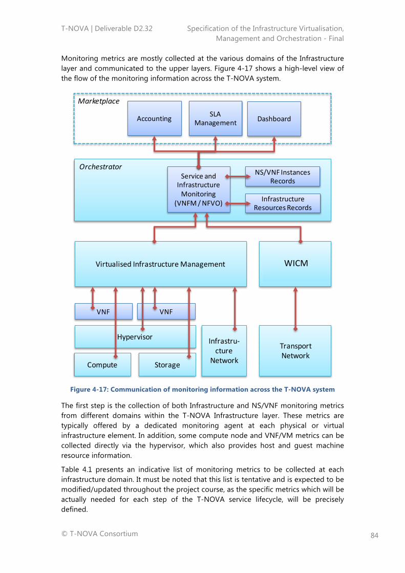
T-NOVA | Deliverable D2.32 Specification of the Infrastructure Virtualisation, Management and Orchestration - Final
© T-NOVA Consortium
84
Monitoring metrics are mostly collected at the various domains of the Infrastructure layer and communicated to the upper layers. Figure 4-17 shows a high-level view of the flow of the monitoring information across the T-NOVA system.
Figure 4-17: Communication of monitoring information across the T-NOVA system
The first step is the collection of both Infrastructure and NS/VNF monitoring metrics from different domains within the T-NOVA Infrastructure layer. These metrics are typically offered by a dedicated monitoring agent at each physical or virtual infrastructure element. In addition, some compute node and VNF/VM metrics can be collected directly via the hypervisor, which also provides host and guest machine resource information.
Table 4.1 presents an indicative list of monitoring metrics to be collected at each infrastructure domain. It must be noted that this list is tentative and is expected to be modified/updated throughout the project course, as the specific metrics which will be actually needed for each step of the T-NOVA service lifecycle, will be precisely defined.
VNF
Marketplace
Orchestrator
Virtualised InfrastructureManagementTransportNetwork
Management
Compute Storage
Infrastru-cture
Network
TransportNetwork
Hypervisor
ServiceandInfrastructureMonitoring
(VNFM/NFVO)
Accounting SLAManagement Dashboard
VNF
NS/VNFInstancesRecords
InfrastructureResourcesRecords
WICM

T-NOVA | Deliverable D2.32 Specification of the Infrastructure Virtualisation, Management and Orchestration - Final
© T-NOVA Consortium
85
Table 4.1: Monitoring metrics per infrastructure domain
Domain VNF App/Service Metrics Infrastructure Metrics
VNF (VM, guest machine) CPU utilisation CPU time used No. of vCPUs RAM allocated Disk read/write bitrate Network interface in/out bitrate No. of processes
-
Compute (per compute node, host machine of the DC domain) -
CPU utilisation RAM allocated Disk read/write bitrate Network interface in/out bitrate
Storage (object or volume storage of the DC domain)
Read/write bitrate Volume usage (volume storage) No. of objects (object storage) Total objects size (object storage)
Total Read/write bitrate Total Volume usage (volume storage) Total no. of objects (object storage) Total objects size (object storage)
Infrastructure Network (per network element of the DC domain)
Per-flow packets cumulative and per second Per-flow bytes packets cumulative and per second Flow duration
Per-port packets cumulative and per second Per-port bytes packets cumulative and per second Per-port receive drops Per-port transmit drops Per-port link state and speed CPU utilisation
Transport Network (per network element)
Per-flow packets cumulative and per second Per-flow bytes packets cumulative and per second Flow duration
Per-port packets cumulative and per second Per-port bytes packets cumulative and per second Per-port receive drops Per-port transmit drops Per-port link state and speed CPU utilisation
Infrastructure metrics, as well as events/alerts are aggregated by the VIM and the WICM and communicated to the Orchestrator FEs, NFVO and VNFM, which are in charge of associating each group of metrics to specific VNFs and Network Service. Those parameters are then compared against the NS and VNF templates composed by a. o. the NSD and the VNFD, which denote the expected NS and VNF behaviour. If any mismatch is detected, appropriate actions are selected and executed, e.g. scaling.
This procedure needs to be carried out at the Orchestrator level, since only the latter has the entire view of the end-to-end service as well as the resources allocated to it. In this context, and in addition to the double check (NS and VNF) mentioned above, the monitoring processed at the Orchestrator, as part of the NFVO and VNFM, performs the following operations:
• Aggregate infrastructure-related metrics and update the Infrastructure Resources records,
T-NOVA | Deliverable D2.32 Specification of the Infrastructure Virtualisation, Management and Orchestration - Final
© T-NOVA Consortium
86
• Associates metrics (e.g. VM and flow metrics) to specific services, produce an integrated picture of the deployed service and updates the NS/VNF instances records,
• Checks monitored parameters against the NS and VNF templates, composed by the NSD and the VNFD, which denote the expected NS and VNF behaviour. If any mismatch is detected, appropriate actions are selected and executed, e.g. scaling,
• Communicate service metrics to the Marketplace via the Orchestrator northbound interface.
At the Marketplace level, service metrics are exploited for accounting (especially in pay-as-you-go billing models) as well as SLA Management, in order to compare the status of the service against the contracted one. They are also presented via the Dashboard to the Customer, so that he/she can have a consolidated overall view of the status of the service and the resources consumed.
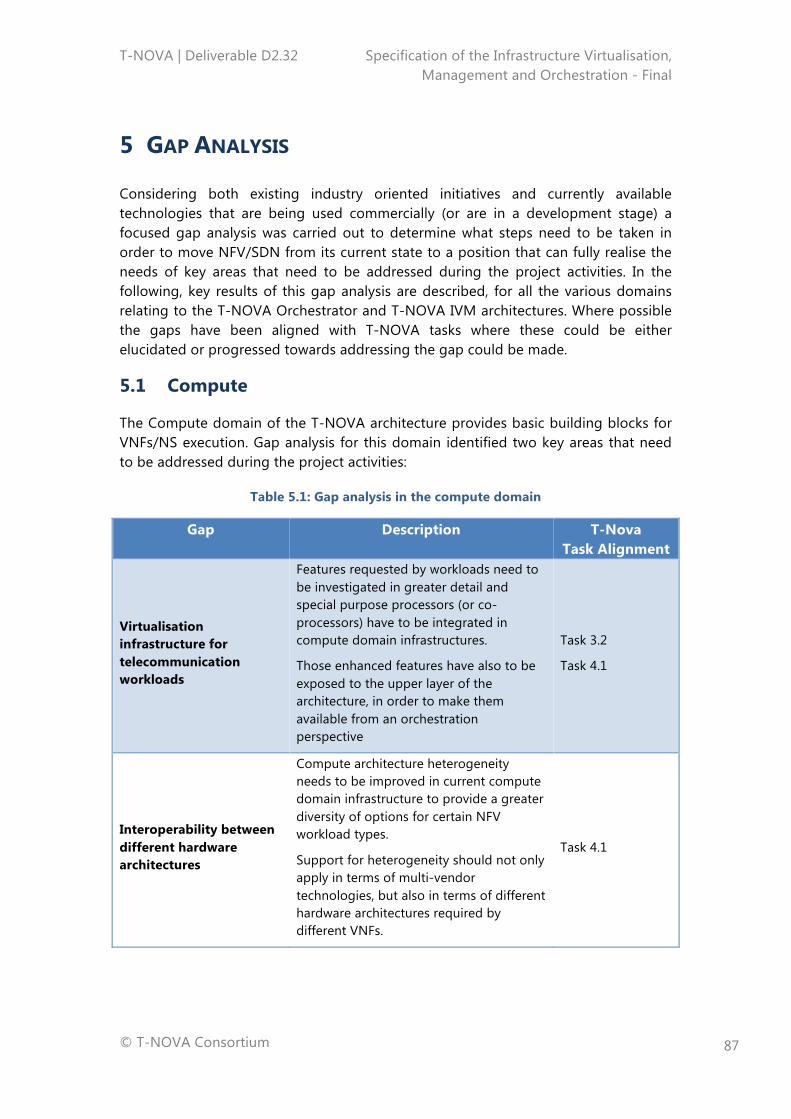
T-NOVA | Deliverable D2.32 Specification of the Infrastructure Virtualisation, Management and Orchestration - Final
© T-NOVA Consortium
87
5 GAP ANALYSIS
Considering both existing industry oriented initiatives and currently available technologies that are being used commercially (or are in a development stage) a focused gap analysis was carried out to determine what steps need to be taken in order to move NFV/SDN from its current state to a position that can fully realise the needs of key areas that need to be addressed during the project activities. In the following, key results of this gap analysis are described, for all the various domains relating to the T-NOVA Orchestrator and T-NOVA IVM architectures. Where possible the gaps have been aligned with T-NOVA tasks where these could be either elucidated or progressed towards addressing the gap could be made.
5.1 Compute
The Compute domain of the T-NOVA architecture provides basic building blocks for VNFs/NS execution. Gap analysis for this domain identified two key areas that need to be addressed during the project activities:
Table 5.1: Gap analysis in the compute domain
Gap Description T-Nova Task Alignment
Virtualisation infrastructure for telecommunication workloads
Features requested by workloads need to be investigated in greater detail and special purpose processors (or co-processors) have to be integrated in compute domain infrastructures.
Those enhanced features have also to be exposed to the upper layer of the architecture, in order to make them available from an orchestration perspective
Task 3.2
Task 4.1
Interoperability between different hardware architectures
Compute architecture heterogeneity needs to be improved in current compute domain infrastructure to provide a greater diversity of options for certain NFV workload types.
Support for heterogeneity should not only apply in terms of multi-vendor technologies, but also in terms of different hardware architectures required by different VNFs.
Task 4.1
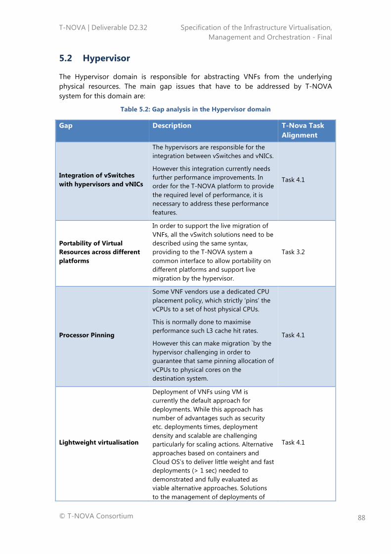
T-NOVA | Deliverable D2.32 Specification of the Infrastructure Virtualisation, Management and Orchestration - Final
© T-NOVA Consortium
88
5.2 Hypervisor
The Hypervisor domain is responsible for abstracting VNFs from the underlying physical resources. The main gap issues that have to be addressed by T-NOVA system for this domain are:
Table 5.2: Gap analysis in the Hypervisor domain
Gap Description T-Nova Task Alignment
Integration of vSwitches with hypervisors and vNICs
The hypervisors are responsible for the integration between vSwitches and vNICs.
However this integration currently needs further performance improvements. In order for the T-NOVA platform to provide the required level of performance, it is necessary to address these performance features.
Task 4.1
Portability of Virtual Resources across different platforms
In order to support the live migration of VNFs, all the vSwitch solutions need to be described using the same syntax, providing to the T-NOVA system a common interface to allow portability on different platforms and support live migration by the hypervisor.
Task 3.2
Processor Pinning
Some VNF vendors use a dedicated CPU placement policy, which strictly ‘pins’ the vCPUs to a set of host physical CPUs.
This is normally done to maximise performance such L3 cache hit rates.
However this can make migration `by the hypervisor challenging in order to guarantee that same pinning allocation of vCPUs to physical cores on the destination system.
Task 4.1
Lightweight virtualisation
Deployment of VNFs using VM is currently the default approach for deployments. While this approach has number of advantages such as security etc. deployments times, deployment density and scalable are challenging particularly for scaling actions. Alternative approaches based on containers and Cloud OS’s to deliver little weight and fast deployments (> 1 sec) needed to demonstrated and fully evaluated as viable alternative approaches. Solutions to the management of deployments of
Task 4.1
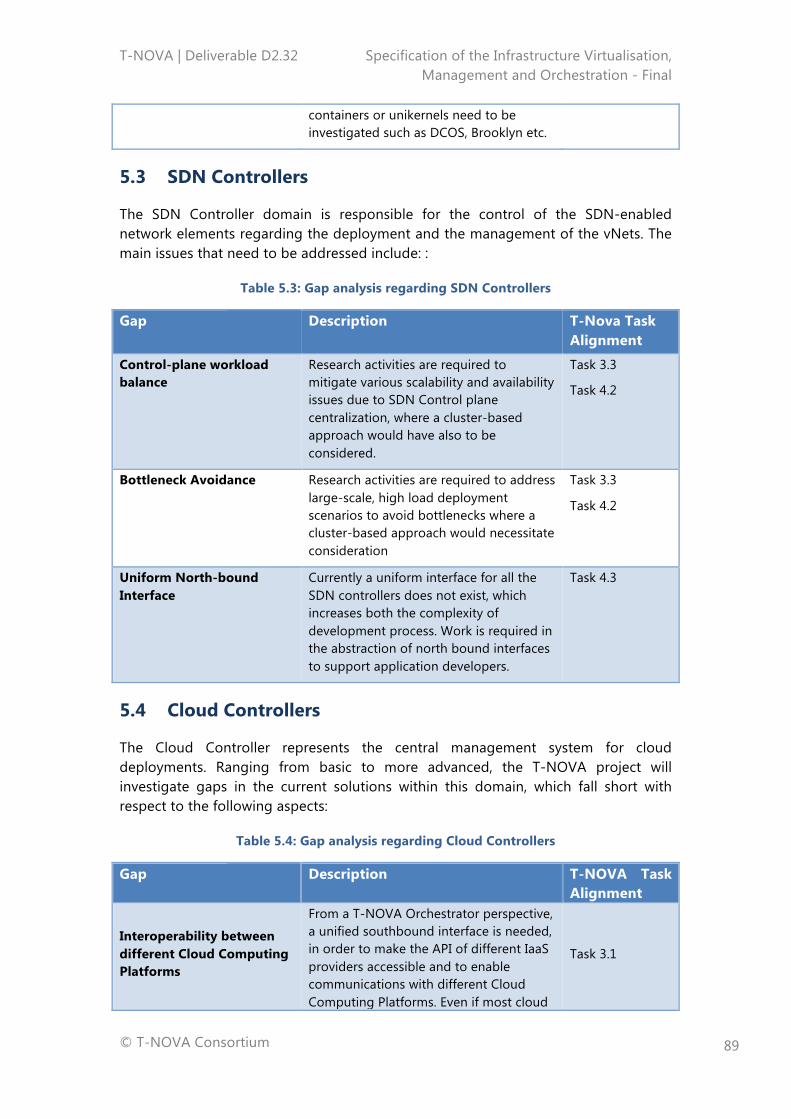
T-NOVA | Deliverable D2.32 Specification of the Infrastructure Virtualisation, Management and Orchestration - Final
© T-NOVA Consortium
89
containers or unikernels need to be investigated such as DCOS, Brooklyn etc.
5.3 SDN Controllers
The SDN Controller domain is responsible for the control of the SDN-enabled network elements regarding the deployment and the management of the vNets. The main issues that need to be addressed include: :
Table 5.3: Gap analysis regarding SDN Controllers
Gap Description T-Nova Task Alignment
Control-plane workload balance
Research activities are required to mitigate various scalability and availability issues due to SDN Control plane centralization, where a cluster-based approach would have also to be considered.
Task 3.3
Task 4.2
Bottleneck Avoidance Research activities are required to address large-scale, high load deployment scenarios to avoid bottlenecks where a cluster-based approach would necessitate consideration
Task 3.3
Task 4.2
Uniform North-bound Interface
Currently a uniform interface for all the SDN controllers does not exist, which increases both the complexity of development process. Work is required in the abstraction of north bound interfaces to support application developers.
Task 4.3
5.4 Cloud Controllers
The Cloud Controller represents the central management system for cloud deployments. Ranging from basic to more advanced, the T-NOVA project will investigate gaps in the current solutions within this domain, which fall short with respect to the following aspects:
Table 5.4: Gap analysis regarding Cloud Controllers
Gap Description T-NOVA Task Alignment
Interoperability between different Cloud Computing Platforms
From a T-NOVA Orchestrator perspective, a unified southbound interface is needed, in order to make the API of different IaaS providers accessible and to enable communications with different Cloud Computing Platforms. Even if most cloud
Task 3.1
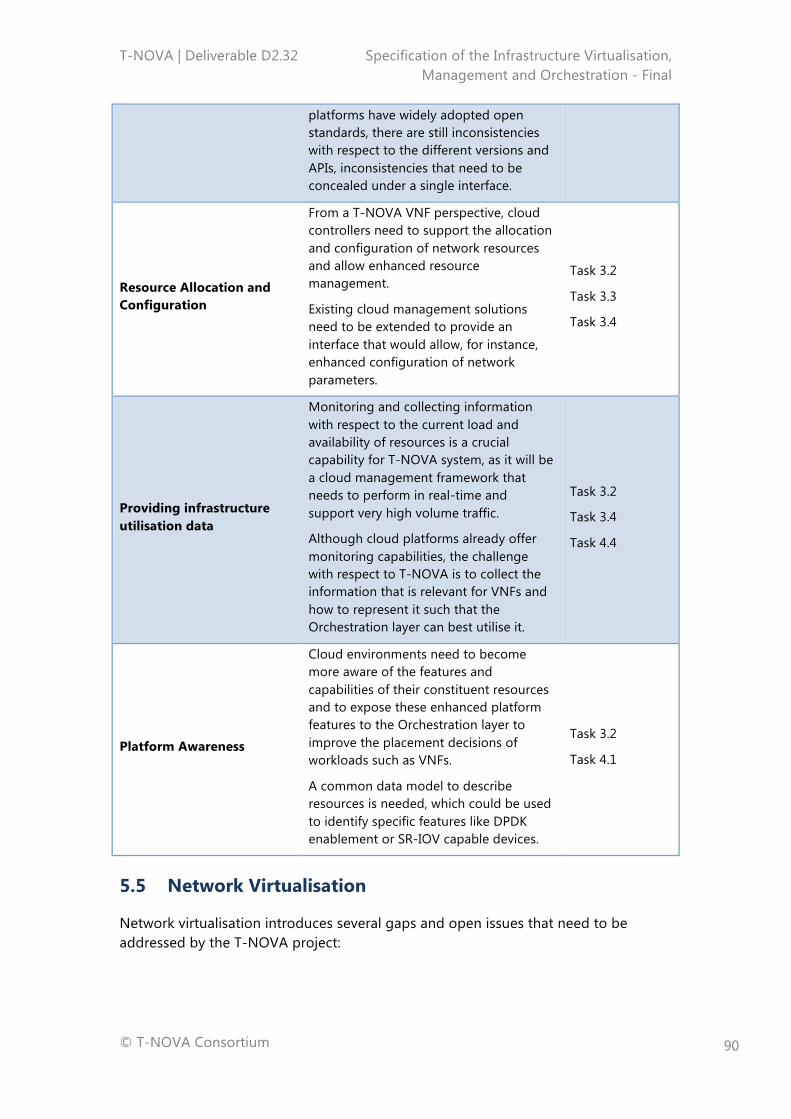
T-NOVA | Deliverable D2.32 Specification of the Infrastructure Virtualisation, Management and Orchestration - Final
© T-NOVA Consortium
90
platforms have widely adopted open standards, there are still inconsistencies with respect to the different versions and APIs, inconsistencies that need to be concealed under a single interface.
Resource Allocation and Configuration
From a T-NOVA VNF perspective, cloud controllers need to support the allocation and configuration of network resources and allow enhanced resource management.
Existing cloud management solutions need to be extended to provide an interface that would allow, for instance, enhanced configuration of network parameters.
Task 3.2
Task 3.3
Task 3.4
Providing infrastructure utilisation data
Monitoring and collecting information with respect to the current load and availability of resources is a crucial capability for T-NOVA system, as it will be a cloud management framework that needs to perform in real-time and support very high volume traffic.
Although cloud platforms already offer monitoring capabilities, the challenge with respect to T-NOVA is to collect the information that is relevant for VNFs and how to represent it such that the Orchestration layer can best utilise it.
Task 3.2
Task 3.4
Task 4.4
Platform Awareness
Cloud environments need to become more aware of the features and capabilities of their constituent resources and to expose these enhanced platform features to the Orchestration layer to improve the placement decisions of workloads such as VNFs.
A common data model to describe resources is needed, which could be used to identify specific features like DPDK enablement or SR-IOV capable devices.
Task 3.2
Task 4.1
5.5 Network Virtualisation
Network virtualisation introduces several gaps and open issues that need to be addressed by the T-NOVA project:
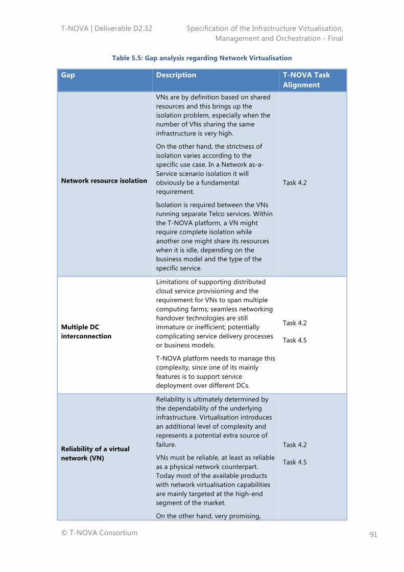
T-NOVA | Deliverable D2.32 Specification of the Infrastructure Virtualisation, Management and Orchestration - Final
© T-NOVA Consortium
91
Table 5.5: Gap analysis regarding Network Virtualisation
Gap Description T-NOVA Task Alignment
Network resource isolation
VNs are by definition based on shared resources and this brings up the isolation problem, especially when the number of VNs sharing the same infrastructure is very high.
On the other hand, the strictness of isolation varies according to the specific use case. In a Network as-a-Service scenario isolation it will obviously be a fundamental requirement.
Isolation is required between the VNs running separate Telco services. Within the T-NOVA platform, a VN might require complete isolation while another one might share its resources when it is idle, depending on the business model and the type of the specific service.
Task 4.2
Multiple DC interconnection
Limitations of supporting distributed cloud service provisioning and the requirement for VNs to span multiple computing farms; seamless networking handover technologies are still immature or inefficient; potentially complicating service delivery processes or business models.
T-NOVA platform needs to manage this complexity, since one of its mainly features is to support service deployment over different DCs.
Task 4.2
Task 4.5
Reliability of a virtual network (VN)
Reliability is ultimately determined by the dependability of the underlying infrastructure. Virtualisation introduces an additional level of complexity and represents a potential extra source of failure.
VNs must be reliable, at least as reliable as a physical network counterpart. Today most of the available products with network virtualisation capabilities are mainly targeted at the high-end segment of the market.
On the other hand, very promising,
Task 4.2
Task 4.5
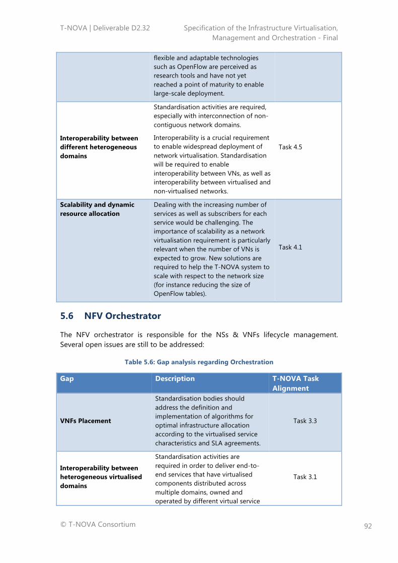
T-NOVA | Deliverable D2.32 Specification of the Infrastructure Virtualisation, Management and Orchestration - Final
© T-NOVA Consortium
92
flexible and adaptable technologies such as OpenFlow are perceived as research tools and have not yet reached a point of maturity to enable large-scale deployment.
Interoperability between different heterogeneous domains
Standardisation activities are required, especially with interconnection of non-contiguous network domains.
Interoperability is a crucial requirement to enable widespread deployment of network virtualisation. Standardisation will be required to enable interoperability between VNs, as well as interoperability between virtualised and non-virtualised networks.
Task 4.5
Scalability and dynamic resource allocation
Dealing with the increasing number of services as well as subscribers for each service would be challenging. The importance of scalability as a network virtualisation requirement is particularly relevant when the number of VNs is expected to grow. New solutions are required to help the T-NOVA system to scale with respect to the network size (for instance reducing the size of OpenFlow tables).
Task 4.1
5.6 NFV Orchestrator
The NFV orchestrator is responsible for the NSs & VNFs lifecycle management. Several open issues are still to be addressed:
Table 5.6: Gap analysis regarding Orchestration
Gap Description T-NOVA Task Alignment
VNFs Placement
Standardisation bodies should address the definition and implementation of algorithms for optimal infrastructure allocation according to the virtualised service characteristics and SLA agreements.
Task 3.3
Interoperability between heterogeneous virtualised domains
Standardisation activities are required in order to deliver end-to-end services that have virtualised components distributed across multiple domains, owned and operated by different virtual service
Task 3.1
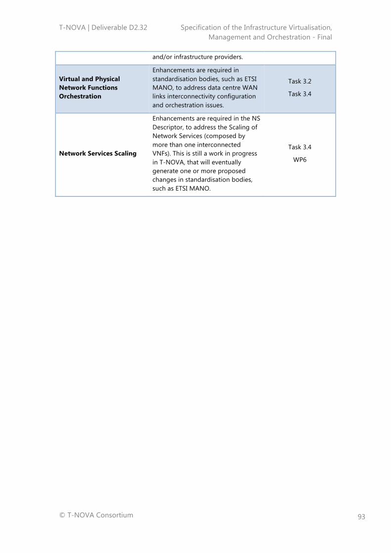
T-NOVA | Deliverable D2.32 Specification of the Infrastructure Virtualisation, Management and Orchestration - Final
© T-NOVA Consortium
93
and/or infrastructure providers.
Virtual and Physical Network Functions Orchestration
Enhancements are required in standardisation bodies, such as ETSI MANO, to address data centre WAN links interconnectivity configuration and orchestration issues.
Task 3.2
Task 3.4
Network Services Scaling
Enhancements are required in the NS Descriptor, to address the Scaling of Network Services (composed by more than one interconnected VNFs). This is still a work in progress in T-NOVA, that will eventually generate one or more proposed changes in standardisation bodies, such as ETSI MANO.
Task 3.4
WP6
T-NOVA | Deliverable D2.32 Specification of the Infrastructure Virtualisation, Management and Orchestration - Final
© T-NOVA Consortium
94
6 CONCLUSIONS
Virtualisation is a foundational technology for the T-NOVA system in particular for the infrastructure virtualisation and management layer. Originating in the compute domain, use of this approach now finds application in a variety of domains including storage and networking. The approach is based on abstracting physical resources into a form that hides its physical characteristics from either users or applications. It brings a variety of benefits including better utilisation of resources, greater flexibility, improved scalability, etc. Virtualisation encompasses a number of technology approaches, at both a hardware and software level.
In the course of reviewing the various virtualisation technologies and considering them in both the context of the telecoms service providers and the potential needs of the T-NOVA system a variety of gaps in the capabilities of the currently available technologies were identified (see Tables 5-1 to 5-6). While the use of virtualisation technologies in the IT domain is well established, adoption of this approach in carrier grade environments to support NFV and SDN proliferation brings a unique set of challenges that do not exist in enterprise IT environments. A variety of further developments will be required to address specific issues in the currently available compute, hypervisor, SDN Controller, Cloud OSs, network virtualisation and orchestration related technologies. Where appropriate, we have mapped T-NOVA tasks whose activities will be related to these technologies challenges or limitations. It is expected that we will further refine these gaps to specific issues identified in implementation of the T-NOVA system, and highlight progress that has been made in further elucidating the characteristics of these problems, as well as the work that T-NOVA has carried out in order to contribute towards a solution.
From an architectural point of view, the T-NOVA Orchestrator is composed by two main building blocks: the NFVO and the VNFM. The NFVO has two main responsibilities, which are accomplished by its two FEs designated by NSO and VRO within the T-NOVA project. The NSO orchestrates the subset of NFVO functions that are responsible for the lifecycle management of Network Services, while the VRO performs the orchestration/management of the virtualised infrastructure resources distributed across multiple DCs. In particular, it performs the mapping of the incoming NS requests to the available virtualised infrastructure resources, as well as the coordination of the resources allocation and placement for each VM that composes the VNF (and the NS). The VRO does this by interacting with the VIM, as well as with the WICM which interacts with the WAN elements for connectivity management purposes.
Since the NSs are composed by VNFs, the NFVO is able to decompose each NS into the constituent VNFs. Although the NFVO has the knowledge of the VNFs that compose the NS, it delegates their lifecycle management to a dedicated FE designated as the VNFM.
In Section 2, the architecture for T-NOVA Orchestrator is presented, taking into account the list of Orchestrator requirements identified after a researching various
T-NOVA | Deliverable D2.32 Specification of the Infrastructure Virtualisation, Management and Orchestration - Final
© T-NOVA Consortium
95
sources such as the use cases defined in D2.1, ETSI ISG NFV requirements, ITU-T requirement for network virtualisation as well as excerpts from the relevant parts of the ETSI ISG MANO WG architecture. The reference architecture and its functionalities outlined in section 2.3 are now being implemented by the various tasks in WP3.
The T-NOVA IVM is responsible for providing the hosting and execution environment for network services in the form of virtualised resources that are abstracted from the physical resources in the compute and infrastructure network domains. A system engineering approach was adopted to define the key functional blocks of the IVM and their interfaces. In addition the key objectives for the IVM were defined. Use of this information and previous T-NOVA deliverables contributed to a requirement capture process that focused on identifying the desired behaviours for the IVM. Requirements where identified for each of the functional entities within the IVM. These requirements where then used in the design of the IVM.
From an architectural perspective the T-NOVA IVM includes three key functional blocks, namely the NFVI, VIM and WICM, which are defined and discussed in Section 3. These functional blocks are comprised of various domains that have specific technology capabilities required for the delivery and management of virtualised resources. For example the NFVI is comprised of the Compute, Hypervisor and Network domains. A number of specific interfaces provide both the internal and external connectivity that integrates the various technology components into a functional IVM. From a T-NOVA system perspective the key external interfaces of the IVM are those to the T-NOVA Orchestrator, which are implemented in the VIM. These interfaces enable the T-NOVA Orchestrator to send requests to the VIM to create and connect VMs in order to support the deployment of VNF service and to manage the virtual resources allocated to the VNFs in order to accomplish to SLAs. Additionally, these interfaces allow the IVM to send infrastructure metrics related to the utilisation and performance to the T-NOVA Orchestrator in order that this entity can perform placement decisions and management of existing deployed services. Another important interface is the one provided by the WICM to the Orchestrator in order for it to manage the network resources related to external networks i.e. WAN transport between DCs.
Collectively, these reference architectures and FEs instantiate the requirements that were identified for the T-NOVA Orchestrator and for the T-NOVA IVM together with its goals and objectives. The reference architectures were interrogated and validated at functional level through the development sequence diagrams as outlined in Section 4, which describe the key actions and interactions taken within the T-NOVA system during standard operational activities related to the deployment and management of NS and VNF services.
T-NOVA | Deliverable D2.32 Specification of the Infrastructure Virtualisation, Management and Orchestration - Final
© T-NOVA Consortium
96
ANNEX A - ORCHESTRATOR REQUIREMENTS
The present annex contains a set of tables, which include the requirements identified in section 2, i.e. Orchestrator internal requirements and Interface requirements.
Each requirement has associated a set of attributes related to its identification (Req. ID and Req. Name), to its text support (Alignment) and to its description (Requirement Description and complementary Comments).
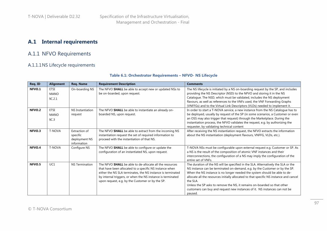
T-NOVA | Deliverable D2.32 Specification of the Infrastructure Virtualisation, Management and Orchestration - Final
© T-NOVA Consortium
97
A.1 Internal requirements
A.1.1 NFVO Requirements
A.1.1.1 NS Lifecycle requirements
Table 6.1: Orchestrator Requirements – NFVO- NS Lifecycle
Req. ID Alignment Req. Name Requirement Description Comments
NFVO.1 ETSI MANO §C.2.1
On-boarding NS The NFVO SHALL be able to accept new or updated NSs to be on-boarded, upon request.
The NS lifecycle is initiated by a NS on-boarding request by the SP, and includes providing the NS Descriptor (NSD) to the NFVO and storing it in the NS Catalogue. The NSD, which must be validated, includes the NS deployment flavours, as well as references to the VNFs used, the VNF Forwarding Graphs (VNFFGs) and to the Virtual Link Descriptors (VLDs) needed to implement it.
NFVO.2 ETSI MANO §C.3
NS Instantiation request
The NFVO SHALL be able to instantiate an already on-boarded NS, upon request.
In order to start a T-NOVA service, a new instance from the NS Catalogue has to be deployed, usually by request of the SP (in some scenarios, a Customer or even an OSS may also trigger that request) through the Marketplace. During the instantiation process, the NFVO validates the request, e.g. by authorizing the requester, by validating technical content
NFVO.3 T-NOVA Extraction of specific deployment NS information
The NFVO SHALL be able to extract from the incoming NS instantiation request the set of required information to proceed with the instantiation of that NS.
After receiving the NS instantiation request, the NFVO extracts the information about the NS instantiation (deployment flavours, VNFFG, VLDs, etc.).
NFVO.4 T-NOVA Configure NS The NFVO SHALL be able to configure or update the configuration of an instantiated NS, upon request.
T-NOVA NSs must be configurable upon external request e.g. Customer or SP. As a NS is the result of the composition of atomic VNF instances and their interconnections, the configuration of a NS may imply the configuration of the entire set of VNFs.
NFVO.5 UC1 NS Termination The NFVO SHALL be able to de-allocate all the resources that have been allocated to a specific NS instance when either the NS SLA terminates, the NS instance is terminated by internal triggers, or when the NS instance is terminated upon request, e.g. by the Customer or by the SP.
The duration of the NS will be specified in the SLA. Alternatively the SLA or the NS instance can be terminated on-demand, e.g. by the Customer or by the SP. When the NS instance is no longer needed the system should be able to de-allocate all the resources initially allocated to that specific NS instance and cancel the SLA. Unless the SP asks to remove the NS, it remains on-boarded so that other customers can buy and request new instances of it. NS instances can not be paused.
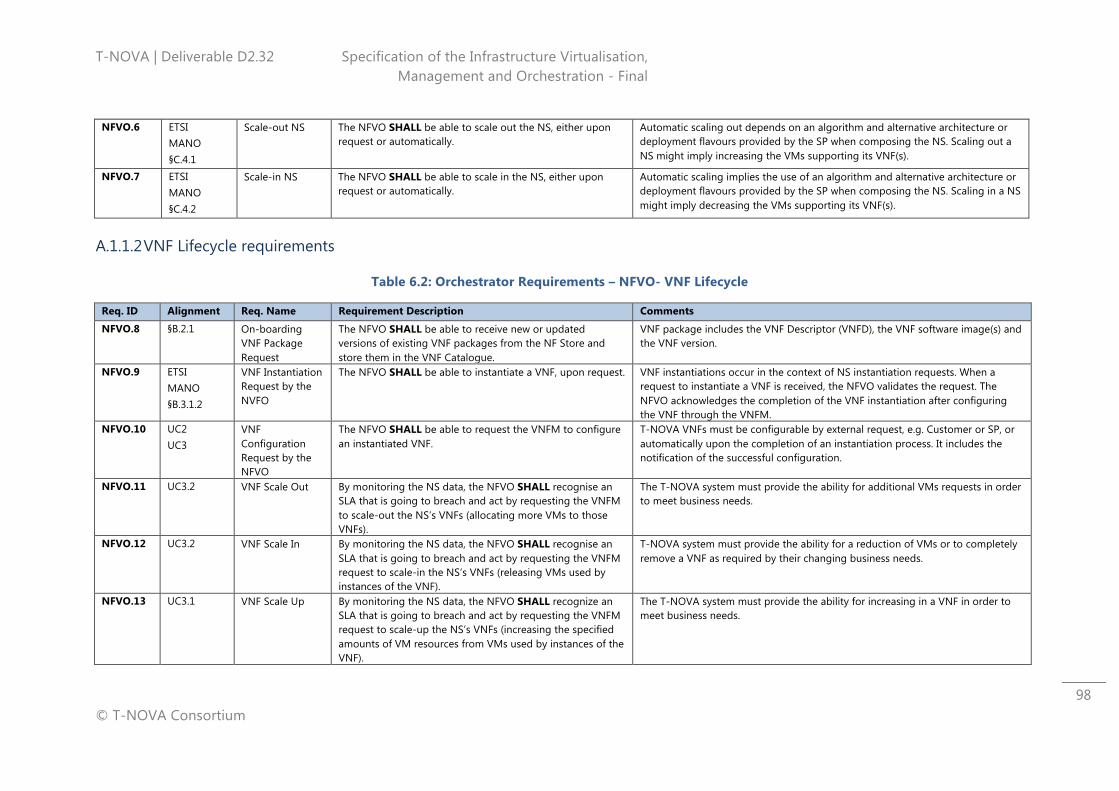
T-NOVA | Deliverable D2.32 Specification of the Infrastructure Virtualisation, Management and Orchestration - Final
© T-NOVA Consortium
98
NFVO.6 ETSI MANO §C.4.1
Scale-out NS The NFVO SHALL be able to scale out the NS, either upon request or automatically.
Automatic scaling out depends on an algorithm and alternative architecture or deployment flavours provided by the SP when composing the NS. Scaling out a NS might imply increasing the VMs supporting its VNF(s).
NFVO.7 ETSI MANO §C.4.2
Scale-in NS The NFVO SHALL be able to scale in the NS, either upon request or automatically.
Automatic scaling implies the use of an algorithm and alternative architecture or deployment flavours provided by the SP when composing the NS. Scaling in a NS might imply decreasing the VMs supporting its VNF(s).
A.1.1.2 VNF Lifecycle requirements
Table 6.2: Orchestrator Requirements – NFVO- VNF Lifecycle
Req. ID Alignment Req. Name Requirement Description Comments
NFVO.8 §B.2.1 On-boarding VNF Package Request
The NFVO SHALL be able to receive new or updated versions of existing VNF packages from the NF Store and store them in the VNF Catalogue.
VNF package includes the VNF Descriptor (VNFD), the VNF software image(s) and the VNF version.
NFVO.9 ETSI MANO §B.3.1.2
VNF Instantiation Request by the NVFO
The NFVO SHALL be able to instantiate a VNF, upon request. VNF instantiations occur in the context of NS instantiation requests. When a request to instantiate a VNF is received, the NFVO validates the request. The NFVO acknowledges the completion of the VNF instantiation after configuring the VNF through the VNFM.
NFVO.10 UC2 UC3
VNF Configuration Request by the NFVO
The NFVO SHALL be able to request the VNFM to configure an instantiated VNF.
T-NOVA VNFs must be configurable by external request, e.g. Customer or SP, or automatically upon the completion of an instantiation process. It includes the notification of the successful configuration.
NFVO.11 UC3.2 VNF Scale Out By monitoring the NS data, the NFVO SHALL recognise an SLA that is going to breach and act by requesting the VNFM to scale-out the NS’s VNFs (allocating more VMs to those VNFs).
The T-NOVA system must provide the ability for additional VMs requests in order to meet business needs.
NFVO.12 UC3.2 VNF Scale In By monitoring the NS data, the NFVO SHALL recognise an SLA that is going to breach and act by requesting the VNFM request to scale-in the NS’s VNFs (releasing VMs used by instances of the VNF).
T-NOVA system must provide the ability for a reduction of VMs or to completely remove a VNF as required by their changing business needs.
NFVO.13 UC3.1 VNF Scale Up By monitoring the NS data, the NFVO SHALL recognize an SLA that is going to breach and act by requesting the VNFM request to scale-up the NS’s VNFs (increasing the specified amounts of VM resources from VMs used by instances of the VNF).
The T-NOVA system must provide the ability for increasing in a VNF in order to meet business needs.
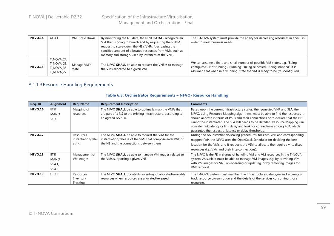
T-NOVA | Deliverable D2.32 Specification of the Infrastructure Virtualisation, Management and Orchestration - Final
© T-NOVA Consortium
99
NFVO.14 UC3.1 VNF Scale Down By monitoring the NS data, the NFVO SHALL recognize an SLA that is going to breach and by requesting the VNFM request to scale-down the NS’s VNFs (decreasing the specified amount of allocated resources from VMs, such as memory and storage, used by instances of the VNF).
The T-NOVA system must provide the ability for decreasing resources in a VNF in order to meet business needs.
NFVO.15
T_NOVA_24, T_NOVA_25, T_NOVA_35, T_NOVA_27
Manage VM’s state
The NFVO SHALL be able to request the VNFM to manage the VMs allocated to a given VNF.
We can assume a finite and small number of possible VM states, e.g., ‘Being configured’, ‘Not running’, ‘Running’, ‘Being re-scaled’, ‘Being stopped’. It is assumed that when in a ‘Running’ state the VM is ready to be (re-)configured.
A.1.1.3 Resource Handling Requirements
Table 6.3: Orchestrator Requirements – NFVO- Resource Handling
Req. ID Alignment Req. Name Requirement Description Comments
NFVO.16 ETSI MANO §C.3
Mapping of resources
The NFVO SHALL be able to optimally map the VNFs that are part of a NS to the existing infrastructure, according to an agreed NS SLA.
Based upon the current infrastructure status, the requested VNF and SLA, the NFVO, using Resource Mapping algorithms, must be able to find the resources it should allocate in terms of PoPs and their connections or to declare that the NS cannot be instantiated. The SLA still needs to be detailed. Resource Mapping can consider link latency or link delay and look for connections among PoP, which guarantee the respect of latency or delay thresholds.
NFVO.17 Resources instantiation/releasing
The NFVO SHALL be able to request the VIM for the instantiation/release of the VMs that compose each VNF of the NS and the connections between them
During the NS instantiation/scaling procedures, for each VNF and corresponding mapped PoP, the NFVO uses the OpenStack Scheduler for deciding the best location for the VMs, and it requests the VIM to allocate the required virtualised resources (i.e.. VMs and their interconnections).
NFVO.18 ETSI MANO §5.4.1, §5.4.3
Management of VM images
The NFVO SHALL be able to manage VM images related to the VMs supporting a given VNF.
The NFVO is the FE in charge of handling VM and VM resources in the T-NOVA system. As such, it must be able to manage VM images, e.g. by providing VIM with VM images for VNF on-boarding or updating, or by removing images for VNF removal.
NFVO.19 UC3.1 Resources Inventory Tracking
The NFVO SHALL update its inventory of allocated/available resources when resources are allocated/released.
The T-NOVA System must maintain the Infrastructure Catalogue and accurately track resource consumption and the details of the services consuming those resources.
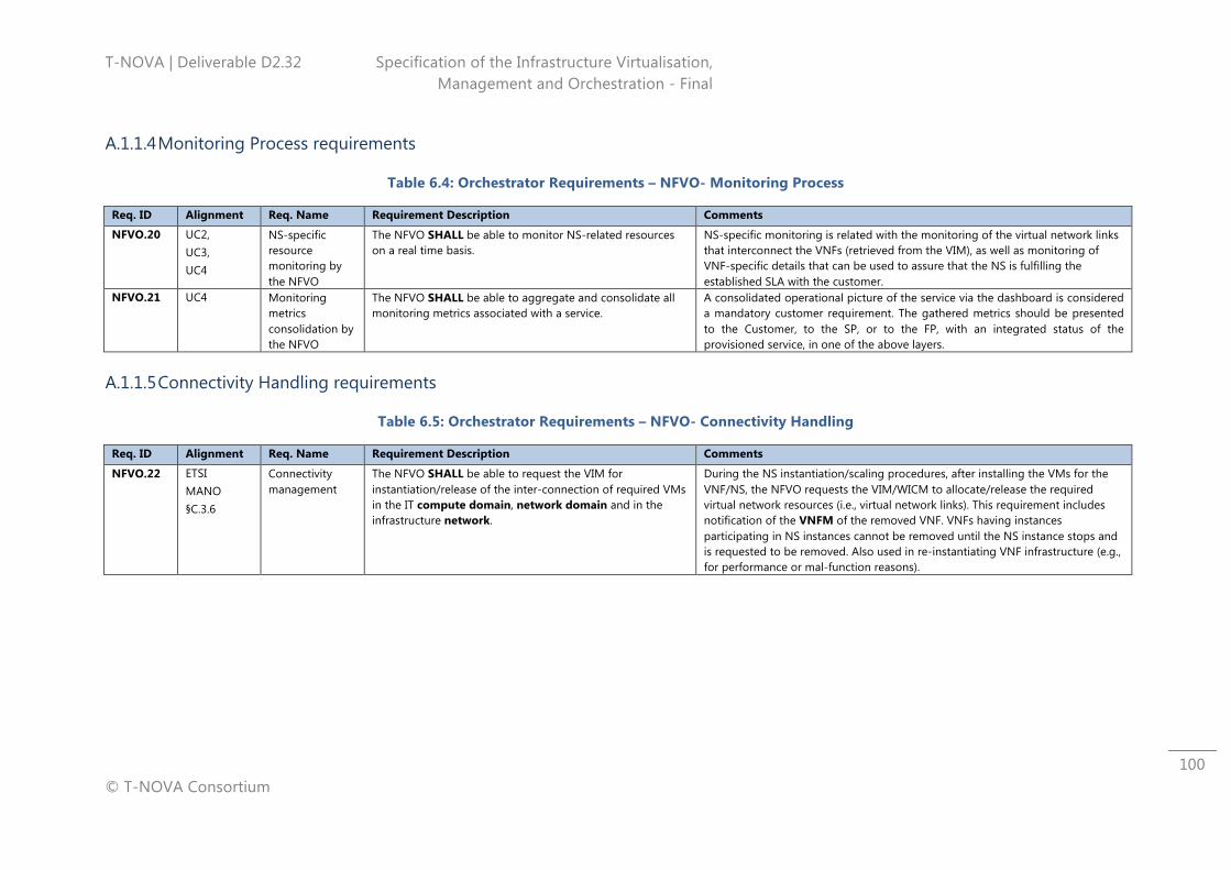
T-NOVA | Deliverable D2.32 Specification of the Infrastructure Virtualisation, Management and Orchestration - Final
© T-NOVA Consortium
100
A.1.1.4 Monitoring Process requirements
Table 6.4: Orchestrator Requirements – NFVO- Monitoring Process
Req. ID Alignment Req. Name Requirement Description Comments
NFVO.20 UC2, UC3, UC4
NS-specific resource monitoring by the NFVO
The NFVO SHALL be able to monitor NS-related resources on a real time basis.
NS-specific monitoring is related with the monitoring of the virtual network links that interconnect the VNFs (retrieved from the VIM), as well as monitoring of VNF-specific details that can be used to assure that the NS is fulfilling the established SLA with the customer.
NFVO.21 UC4 Monitoring metrics consolidation by the NFVO
The NFVO SHALL be able to aggregate and consolidate all monitoring metrics associated with a service.
A consolidated operational picture of the service via the dashboard is considered a mandatory customer requirement. The gathered metrics should be presented to the Customer, to the SP, or to the FP, with an integrated status of the provisioned service, in one of the above layers.
A.1.1.5 Connectivity Handling requirements
Table 6.5: Orchestrator Requirements – NFVO- Connectivity Handling
Req. ID Alignment Req. Name Requirement Description Comments
NFVO.22 ETSI MANO §C.3.6
Connectivity management
The NFVO SHALL be able to request the VIM for instantiation/release of the inter-connection of required VMs in the IT compute domain, network domain and in the infrastructure network.
During the NS instantiation/scaling procedures, after installing the VMs for the VNF/NS, the NFVO requests the VIM/WICM to allocate/release the required virtual network resources (i.e., virtual network links). This requirement includes notification of the VNFM of the removed VNF. VNFs having instances participating in NS instances cannot be removed until the NS instance stops and is requested to be removed. Also used in re-instantiating VNF infrastructure (e.g., for performance or mal-function reasons).
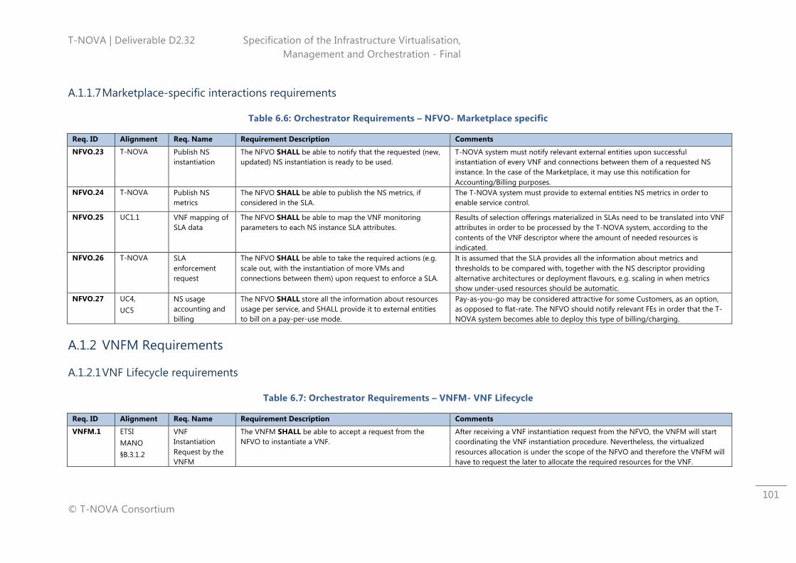
T-NOVA | Deliverable D2.32 Specification of the Infrastructure Virtualisation, Management and Orchestration - Final
© T-NOVA Consortium
101
A.1.1.7 Marketplace-specific interactions requirements
Table 6.6: Orchestrator Requirements – NFVO- Marketplace specific
Req. ID Alignment Req. Name Requirement Description Comments
NFVO.23 T-NOVA Publish NS instantiation
The NFVO SHALL be able to notify that the requested (new, updated) NS instantiation is ready to be used.
T-NOVA system must notify relevant external entities upon successful instantiation of every VNF and connections between them of a requested NS instance. In the case of the Marketplace, it may use this notification for Accounting/Billing purposes.
NFVO.24 T-NOVA Publish NS metrics
The NFVO SHALL be able to publish the NS metrics, if considered in the SLA.
The T-NOVA system must provide to external entities NS metrics in order to enable service control.
NFVO.25 UC1.1 VNF mapping of SLA data
The NFVO SHALL be able to map the VNF monitoring parameters to each NS instance SLA attributes.
Results of selection offerings materialized in SLAs need to be translated into VNF attributes in order to be processed by the T-NOVA system, according to the contents of the VNF descriptor where the amount of needed resources is indicated.
NFVO.26 T-NOVA SLA enforcement request
The NFVO SHALL be able to take the required actions (e.g. scale out, with the instantiation of more VMs and connections between them) upon request to enforce a SLA.
It is assumed that the SLA provides all the information about metrics and thresholds to be compared with, together with the NS descriptor providing alternative architectures or deployment flavours, e.g. scaling in when metrics show under-used resources should be automatic.
NFVO.27 UC4, UC5
NS usage accounting and billing
The NFVO SHALL store all the information about resources usage per service, and SHALL provide it to external entities to bill on a pay-per-use mode.
Pay-as-you-go may be considered attractive for some Customers, as an option, as opposed to flat-rate. The NFVO should notify relevant FEs in order that the T-NOVA system becomes able to deploy this type of billing/charging.
A.1.2 VNFM Requirements
A.1.2.1 VNF Lifecycle requirements
Table 6.7: Orchestrator Requirements – VNFM- VNF Lifecycle
Req. ID Alignment Req. Name Requirement Description Comments
VNFM.1 ETSI MANO §B.3.1.2
VNF Instantiation Request by the VNFM
The VNFM SHALL be able to accept a request from the NFVO to instantiate a VNF.
After receiving a VNF instantiation request from the NFVO, the VNFM will start coordinating the VNF instantiation procedure. Nevertheless, the virtualized resources allocation is under the scope of the NFVO and therefore the VNFM will have to request the later to allocate the required resources for the VNF.
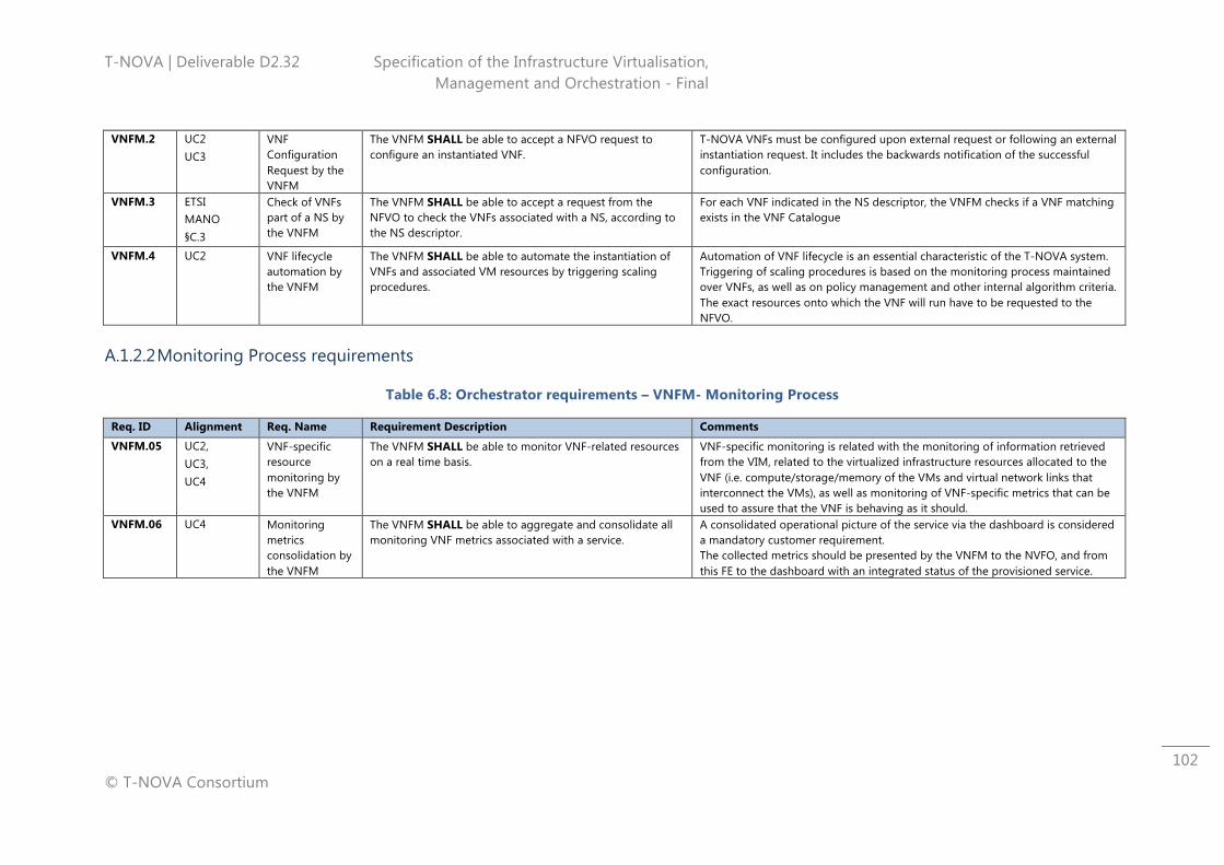
T-NOVA | Deliverable D2.32 Specification of the Infrastructure Virtualisation, Management and Orchestration - Final
© T-NOVA Consortium
102
VNFM.2 UC2 UC3
VNF Configuration Request by the VNFM
The VNFM SHALL be able to accept a NFVO request to configure an instantiated VNF.
T-NOVA VNFs must be configured upon external request or following an external instantiation request. It includes the backwards notification of the successful configuration.
VNFM.3 ETSI MANO §C.3
Check of VNFs part of a NS by the VNFM
The VNFM SHALL be able to accept a request from the NFVO to check the VNFs associated with a NS, according to the NS descriptor.
For each VNF indicated in the NS descriptor, the VNFM checks if a VNF matching exists in the VNF Catalogue
VNFM.4 UC2 VNF lifecycle automation by the VNFM
The VNFM SHALL be able to automate the instantiation of VNFs and associated VM resources by triggering scaling procedures.
Automation of VNF lifecycle is an essential characteristic of the T-NOVA system. Triggering of scaling procedures is based on the monitoring process maintained over VNFs, as well as on policy management and other internal algorithm criteria. The exact resources onto which the VNF will run have to be requested to the NFVO.
A.1.2.2 Monitoring Process requirements
Table 6.8: Orchestrator requirements – VNFM- Monitoring Process
Req. ID Alignment Req. Name Requirement Description Comments
VNFM.05 UC2, UC3, UC4
VNF-specific resource monitoring by the VNFM
The VNFM SHALL be able to monitor VNF-related resources on a real time basis.
VNF-specific monitoring is related with the monitoring of information retrieved from the VIM, related to the virtualized infrastructure resources allocated to the VNF (i.e. compute/storage/memory of the VMs and virtual network links that interconnect the VMs), as well as monitoring of VNF-specific metrics that can be used to assure that the VNF is behaving as it should.
VNFM.06 UC4 Monitoring metrics consolidation by the VNFM
The VNFM SHALL be able to aggregate and consolidate all monitoring VNF metrics associated with a service.
A consolidated operational picture of the service via the dashboard is considered a mandatory customer requirement. The collected metrics should be presented by the VNFM to the NVFO, and from this FE to the dashboard with an integrated status of the provisioned service.
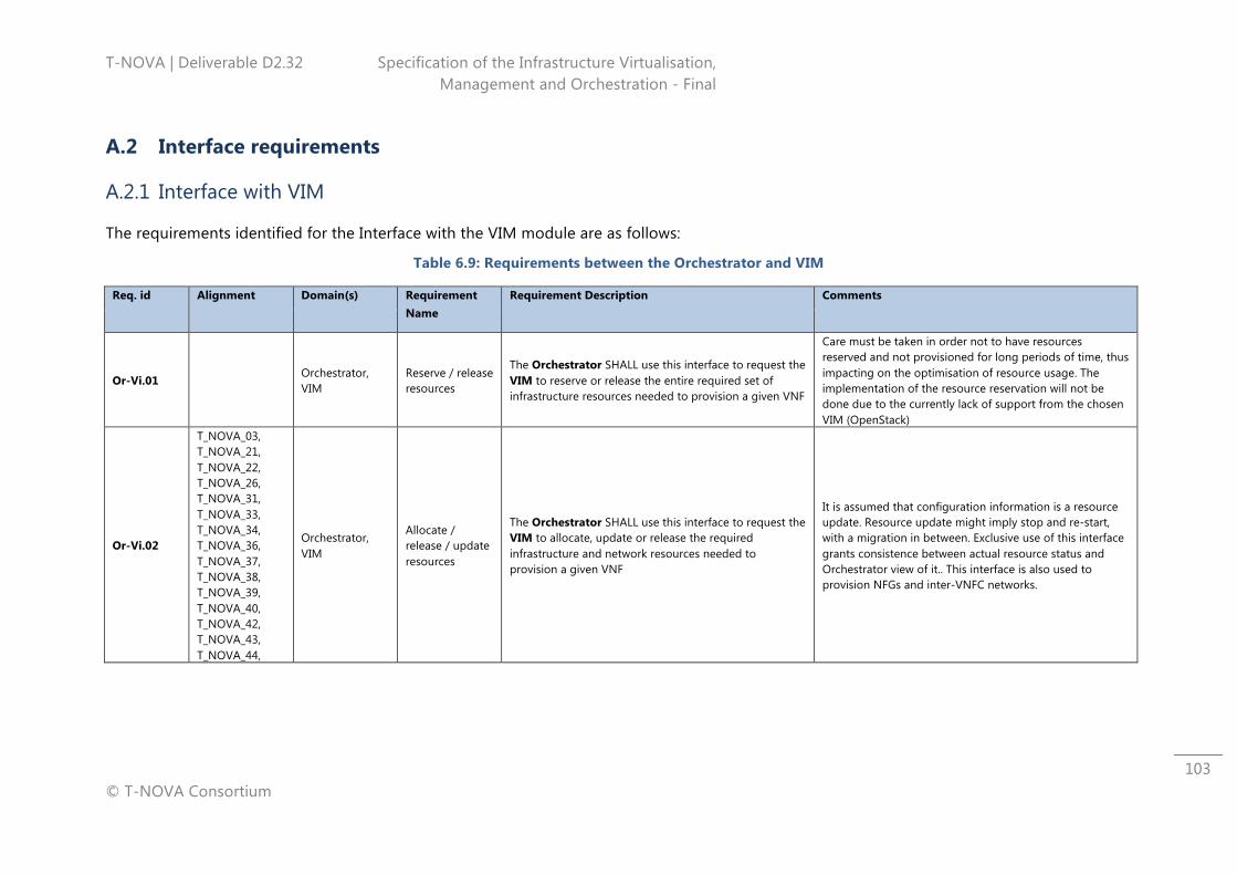
T-NOVA | Deliverable D2.32 Specification of the Infrastructure Virtualisation, Management and Orchestration - Final
© T-NOVA Consortium
103
A.2 Interface requirements
A.2.1 Interface with VIM
The requirements identified for the Interface with the VIM module are as follows:
Table 6.9: Requirements between the Orchestrator and VIM
Req. id Alignment Domain(s) Requirement Name
Requirement Description Comments
Or-Vi.01 Orchestrator, VIM
Reserve / release resources
The Orchestrator SHALL use this interface to request the VIM to reserve or release the entire required set of infrastructure resources needed to provision a given VNF
Care must be taken in order not to have resources reserved and not provisioned for long periods of time, thus impacting on the optimisation of resource usage. The implementation of the resource reservation will not be done due to the currently lack of support from the chosen VIM (OpenStack)
Or-Vi.02
T_NOVA_03, T_NOVA_21, T_NOVA_22, T_NOVA_26, T_NOVA_31, T_NOVA_33, T_NOVA_34, T_NOVA_36, T_NOVA_37, T_NOVA_38, T_NOVA_39, T_NOVA_40, T_NOVA_42, T_NOVA_43, T_NOVA_44,
Orchestrator, VIM
Allocate / release / update resources
The Orchestrator SHALL use this interface to request the VIM to allocate, update or release the required infrastructure and network resources needed to provision a given VNF
It is assumed that configuration information is a resource update. Resource update might imply stop and re-start, with a migration in between. Exclusive use of this interface grants consistence between actual resource status and Orchestrator view of it.. This interface is also used to provision NFGs and inter-VNFC networks.
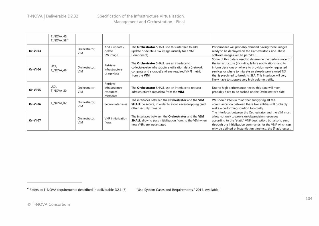
T-NOVA | Deliverable D2.32 Specification of the Infrastructure Virtualisation, Management and Orchestration - Final
© T-NOVA Consortium
104
T_NOVA_45, T_NOVA_58 6
Or-Vi.03 Orchestrator, VIM
Add / update / delete SW image
The Orchestrator SHALL use this interface to add, update or delete a SW image (usually for a VNF Component)
Performance will probably demand having these images ready to be deployed on the Orchestrator’s side. These software images will be per VDU.
Or-Vi.04 UC4, T_NOVA_46
Orchestrator, VIM
Retrieve infrastructure usage data
The Orchestrator SHALL use an interface to collect/receive infrastructure utilisation data (network, compute and storage) and any required VNFI metric from the VIM
Some of this data is used to determine the performance of the infrastructure (including failure notifications) and to inform decisions on where to provision newly requested services or where to migrate an already provisioned NS that is predicted to break its SLA. This interface will very likely have to support very high volume traffic.
Or-Vi.05 UC4, T_NOVA_20
Orchestrator, VIM
Retrieve infrastructure resources metadata
The Orchestrator SHALL use an interface to request infrastructure's metadata from the VIM
Due to high performance needs, this data will most probably have to be cached on the Orchestrator’s side.
Or-Vi.06 T_NOVA_02 Orchestrator, VIM
Secure interfaces The interfaces between the Orchestrator and the VIM SHALL be secure, in order to avoid eavesdropping (and other security threats)
We should keep in mind that encrypting all the communication between these two entities will probably make a performing solution too costly
Or-Vi.07 Orchestrator, VIM
VNF initialization flows
The interfaces between the Orchestrator and the VIM SHALL allow to pass initialization flows to the VIM when new VNFs are instantiated
The interfaces between the Orchestrator and the VIM must allow not only to provision/deprovision resources according to the “static” VNF description, but also to send through the initialization commands for the VNF which can only be defined at instantiation time (e.g. the IP addresses).
6 Refers to T-NOVA requirements described in deliverable D2.1 [6] "Use System Cases and Requirements," 2014. Available:
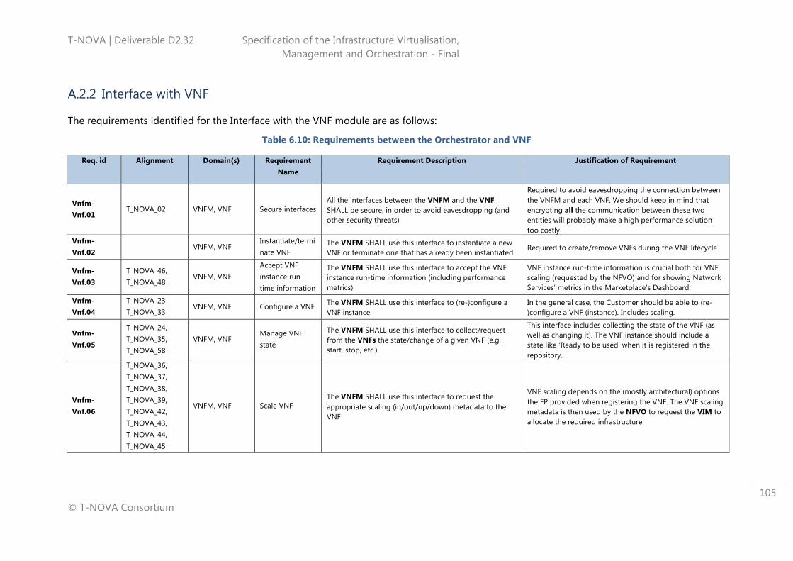
T-NOVA | Deliverable D2.32 Specification of the Infrastructure Virtualisation, Management and Orchestration - Final
© T-NOVA Consortium
105
A.2.2 Interface with VNF
The requirements identified for the Interface with the VNF module are as follows:
Table 6.10: Requirements between the Orchestrator and VNF
Req. id Alignment Domain(s) Requirement Name
Requirement Description Justification of Requirement
Vnfm-Vnf.01
T_NOVA_02 VNFM, VNF Secure interfaces All the interfaces between the VNFM and the VNF SHALL be secure, in order to avoid eavesdropping (and other security threats)
Required to avoid eavesdropping the connection between the VNFM and each VNF. We should keep in mind that encrypting all the communication between these two entities will probably make a high performance solution too costly
Vnfm-Vnf.02
VNFM, VNF Instantiate/terminate VNF
The VNFM SHALL use this interface to instantiate a new VNF or terminate one that has already been instantiated
Required to create/remove VNFs during the VNF lifecycle
Vnfm-Vnf.03
T_NOVA_46, T_NOVA_48
VNFM, VNF Accept VNF instance run-time information
The VNFM SHALL use this interface to accept the VNF instance run-time information (including performance metrics)
VNF instance run-time information is crucial both for VNF scaling (requested by the NFVO) and for showing Network Services’ metrics in the Marketplace’s Dashboard
Vnfm-Vnf.04
T_NOVA_23 T_NOVA_33
VNFM, VNF Configure a VNF The VNFM SHALL use this interface to (re-)configure a VNF instance
In the general case, the Customer should be able to (re-)configure a VNF (instance). Includes scaling.
Vnfm-Vnf.05
T_NOVA_24, T_NOVA_35, T_NOVA_58
VNFM, VNF Manage VNF state
The VNFM SHALL use this interface to collect/request from the VNFs the state/change of a given VNF (e.g. start, stop, etc.)
This interface includes collecting the state of the VNF (as well as changing it). The VNF instance should include a state like ‘Ready to be used’ when it is registered in the repository.
Vnfm-Vnf.06
T_NOVA_36, T_NOVA_37, T_NOVA_38, T_NOVA_39, T_NOVA_42, T_NOVA_43, T_NOVA_44, T_NOVA_45
VNFM, VNF Scale VNF The VNFM SHALL use this interface to request the appropriate scaling (in/out/up/down) metadata to the VNF
VNF scaling depends on the (mostly architectural) options the FP provided when registering the VNF. The VNF scaling metadata is then used by the NFVO to request the VIM to allocate the required infrastructure
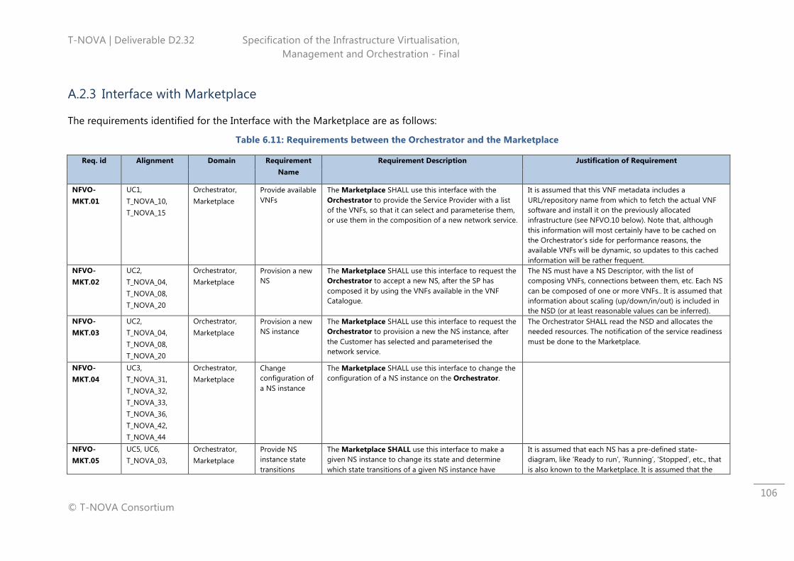
T-NOVA | Deliverable D2.32 Specification of the Infrastructure Virtualisation, Management and Orchestration - Final
© T-NOVA Consortium
106
A.2.3 Interface with Marketplace
The requirements identified for the Interface with the Marketplace are as follows:
Table 6.11: Requirements between the Orchestrator and the Marketplace
Req. id Alignment Domain Requirement Name
Requirement Description Justification of Requirement
NFVO-MKT.01
UC1, T_NOVA_10, T_NOVA_15
Orchestrator, Marketplace
Provide available VNFs
The Marketplace SHALL use this interface with the Orchestrator to provide the Service Provider with a list of the VNFs, so that it can select and parameterise them, or use them in the composition of a new network service.
It is assumed that this VNF metadata includes a URL/repository name from which to fetch the actual VNF software and install it on the previously allocated infrastructure (see NFVO.10 below). Note that, although this information will most certainly have to be cached on the Orchestrator’s side for performance reasons, the available VNFs will be dynamic, so updates to this cached information will be rather frequent.
NFVO-MKT.02
UC2, T_NOVA_04, T_NOVA_08, T_NOVA_20
Orchestrator, Marketplace
Provision a new NS
The Marketplace SHALL use this interface to request the Orchestrator to accept a new NS, after the SP has composed it by using the VNFs available in the VNF Catalogue.
The NS must have a NS Descriptor, with the list of composing VNFs, connections between them, etc. Each NS can be composed of one or more VNFs.. It is assumed that information about scaling (up/down/in/out) is included in the NSD (or at least reasonable values can be inferred).
NFVO-MKT.03
UC2, T_NOVA_04, T_NOVA_08, T_NOVA_20
Orchestrator, Marketplace
Provision a new NS instance
The Marketplace SHALL use this interface to request the Orchestrator to provision a new the NS instance, after the Customer has selected and parameterised the network service.
The Orchestrator SHALL read the NSD and allocates the needed resources. The notification of the service readiness must be done to the Marketplace.
NFVO-MKT.04
UC3, T_NOVA_31, T_NOVA_32, T_NOVA_33, T_NOVA_36, T_NOVA_42, T_NOVA_44
Orchestrator, Marketplace
Change configuration of a NS instance
The Marketplace SHALL use this interface to change the configuration of a NS instance on the Orchestrator.
NFVO-MKT.05
UC5, UC6, T_NOVA_03,
Orchestrator, Marketplace
Provide NS instance state transitions
The Marketplace SHALL use this interface to make a given NS instance to change its state and determine which state transitions of a given NS instance have
It is assumed that each NS has a pre-defined state-diagram, like ‘Ready to run’, ‘Running’, ‘Stopped’, etc., that is also known to the Marketplace. It is assumed that the
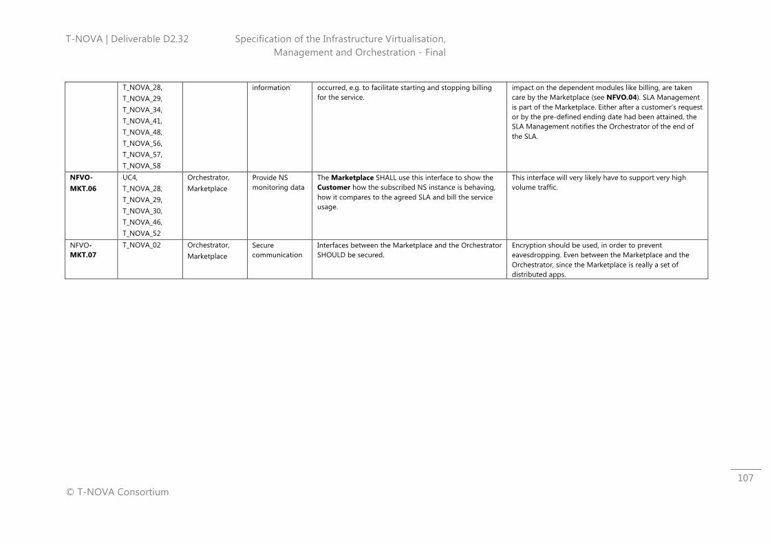
T-NOVA | Deliverable D2.32 Specification of the Infrastructure Virtualisation, Management and Orchestration - Final
© T-NOVA Consortium
107
T_NOVA_28, T_NOVA_29, T_NOVA_34, T_NOVA_41, T_NOVA_48, T_NOVA_56, T_NOVA_57, T_NOVA_58
information occurred, e.g. to facilitate starting and stopping billing for the service.
impact on the dependent modules like billing, are taken care by the Marketplace (see NFVO.04). SLA Management is part of the Marketplace. Either after a customer’s request or by the pre-defined ending date had been attained, the SLA Management notifies the Orchestrator of the end of the SLA.
NFVO-MKT.06
UC4, T_NOVA_28, T_NOVA_29, T_NOVA_30, T_NOVA_46, T_NOVA_52
Orchestrator, Marketplace
Provide NS monitoring data
The Marketplace SHALL use this interface to show the Customer how the subscribed NS instance is behaving, how it compares to the agreed SLA and bill the service usage.
This interface will very likely have to support very high volume traffic.
NFVO-MKT.07
T_NOVA_02 Orchestrator, Marketplace
Secure communication
Interfaces between the Marketplace and the Orchestrator SHOULD be secured.
Encryption should be used, in order to prevent eavesdropping. Even between the Marketplace and the Orchestrator, since the Marketplace is really a set of distributed apps.
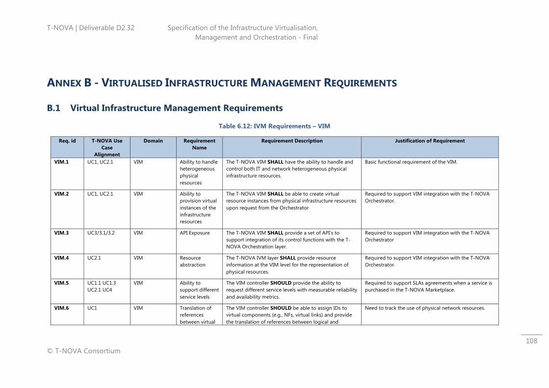
T-NOVA | Deliverable D2.32 Specification of the Infrastructure Virtualisation, Management and Orchestration - Final
© T-NOVA Consortium
108
ANNEX B - VIRTUALISED INFRASTRUCTURE MANAGEMENT REQUIREMENTS
B.1 Virtual Infrastructure Management Requirements
Table 6.12: IVM Requirements – VIM
Req. id T-NOVA Use Case
Alignment
Domain Requirement Name
Requirement Description Justification of Requirement
VIM.1 UC1, UC2.1 VIM Ability to handle heterogeneous physical resources
The T-NOVA VIM SHALL have the ability to handle and control both IT and network heterogeneous physical infrastructure resources.
Basic functional requirement of the VIM.
VIM.2 UC1, UC2.1 VIM Ability to provision virtual instances of the infrastructure resources
The T-NOVA VIM SHALL be able to create virtual resource instances from physical infrastructure resources upon request from the Orchestrator
Required to support VIM integration with the T-NOVA Orchestrator.
VIM.3 UC3/3.1/3.2 VIM API Exposure The T-NOVA VIM SHALL provide a set of API’s to support integration of its control functions with the T-NOVA Orchestration layer.
Required to support VIM integration with the T-NOVA Orchestrator
VIM.4 UC2.1 VIM Resource abstraction
The T-NOVA IVM layer SHALL provide resource information at the VIM level for the representation of physical resources.
Required to support VIM integration with the T-NOVA Orchestrator.
VIM.5 UC1.1 UC1.3 UC2.1 UC4
VIM Ability to support different service levels
The VIM controller SHOULD provide the ability to request different service levels with measurable reliability and availability metrics.
Required to support SLAs agreements when a service is purchased in the T-NOVA Marketplace.
VIM.6 UC1 VIM Translation of references between virtual
The VIM controller SHOULD be able to assign IDs to virtual components (e.g., NFs, virtual links) and provide the translation of references between logical and
Need to track the use of physical network resources.
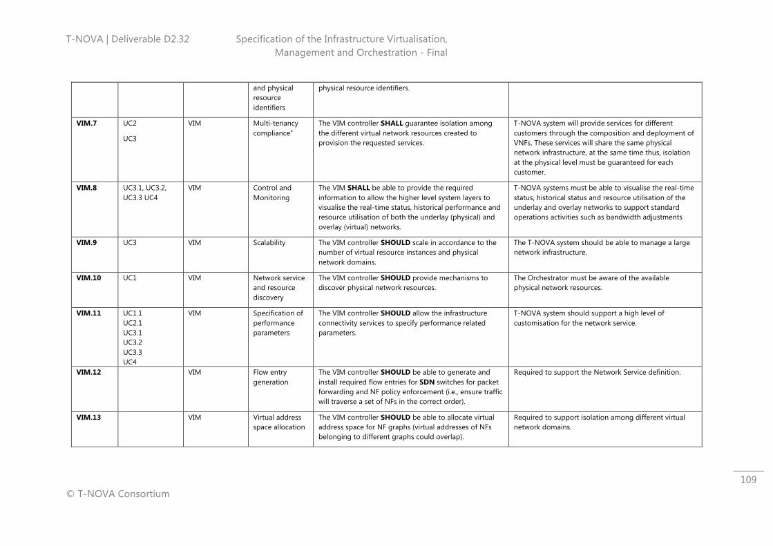
T-NOVA | Deliverable D2.32 Specification of the Infrastructure Virtualisation, Management and Orchestration - Final
© T-NOVA Consortium
109
and physical resource identifiers
physical resource identifiers.
VIM.7 UC2
UC3
VIM Multi-tenancy compliance”
The VIM controller SHALL guarantee isolation among the different virtual network resources created to provision the requested services.
T-NOVA system will provide services for different customers through the composition and deployment of VNFs. These services will share the same physical network infrastructure, at the same time thus, isolation at the physical level must be guaranteed for each customer.
VIM.8 UC3.1, UC3.2, UC3.3 UC4
VIM Control and Monitoring
The VIM SHALL be able to provide the required information to allow the higher level system layers to visualise the real-time status, historical performance and resource utilisation of both the underlay (physical) and overlay (virtual) networks.
T-NOVA systems must be able to visualise the real-time status, historical status and resource utilisation of the underlay and overlay networks to support standard operations activities such as bandwidth adjustments
VIM.9 UC3 VIM Scalability The VIM controller SHOULD scale in accordance to the number of virtual resource instances and physical network domains.
The T-NOVA system should be able to manage a large network infrastructure.
VIM.10 UC1 VIM Network service and resource discovery
The VIM controller SHOULD provide mechanisms to discover physical network resources.
The Orchestrator must be aware of the available physical network resources.
VIM.11 UC1.1 UC2.1 UC3.1 UC3.2 UC3.3 UC4
VIM Specification of performance parameters
The VIM controller SHOULD allow the infrastructure connectivity services to specify performance related parameters.
T-NOVA system should support a high level of customisation for the network service.
VIM.12 VIM Flow entry generation
The VIM controller SHOULD be able to generate and install required flow entries for SDN switches for packet forwarding and NF policy enforcement (i.e., ensure traffic will traverse a set of NFs in the correct order).
Required to support the Network Service definition.
VIM.13 VIM Virtual address space allocation
The VIM controller SHOULD be able to allocate virtual address space for NF graphs (virtual addresses of NFs belonging to different graphs could overlap).
Required to support isolation among different virtual network domains.
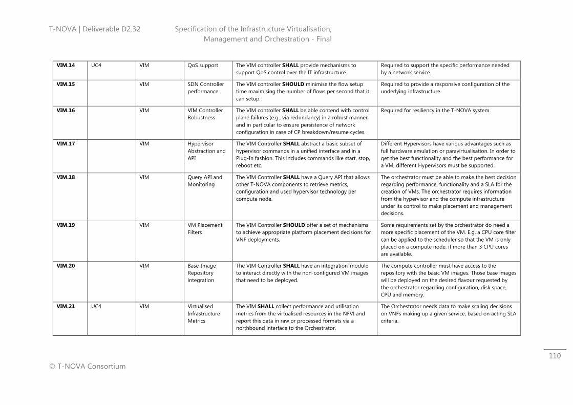
T-NOVA | Deliverable D2.32 Specification of the Infrastructure Virtualisation, Management and Orchestration - Final
© T-NOVA Consortium
110
VIM.14 UC4 VIM QoS support The VIM controller SHALL provide mechanisms to support QoS control over the IT infrastructure.
Required to support the specific performance needed by a network service.
VIM.15 VIM SDN Controller performance
The VIM controller SHOULD minimise the flow setup time maximising the number of flows per second that it can setup.
Required to provide a responsive configuration of the underlying infrastructure.
VIM.16 VIM VIM Controller Robustness
The VIM controller SHALL be able contend with control plane failures (e.g., via redundancy) in a robust manner, and in particular to ensure persistence of network configuration in case of CP breakdown/resume cycles.
Required for resiliency in the T-NOVA system.
VIM.17 VIM Hypervisor Abstraction and API
The VIM Controller SHALL abstract a basic subset of hypervisor commands in a unified interface and in a Plug-In fashion. This includes commands like start, stop, reboot etc.
Different Hypervisors have various advantages such as full hardware emulation or paravirtualisation. In order to get the best functionality and the best performance for a VM, different Hypervisors must be supported.
VIM.18 VIM Query API and Monitoring
The VIM Controller SHALL have a Query API that allows other T-NOVA components to retrieve metrics, configuration and used hypervisor technology per compute node.
The orchestrator must be able to make the best decision regarding performance, functionality and a SLA for the creation of VMs. The orchestrator requires information from the hypervisor and the compute infrastructure under its control to make placement and management decisions.
VIM.19 VIM VM Placement Filters
The VIM Controller SHOULD offer a set of mechanisms to achieve appropriate platform placement decisions for VNF deployments.
Some requirements set by the orchestrator do need a more specific placement of the VM. E.g. a CPU core filter can be applied to the scheduler so that the VM is only placed on a compute node, if more than 3 CPU cores are available.
VIM.20 VIM Base-Image Repository integration
The VIM Controller SHALL have an integration-module to interact directly with the non-configured VM images that need to be deployed.
The compute controller must have access to the repository with the basic VM images. Those base images will be deployed on the desired flavour requested by the orchestrator regarding configuration, disk space, CPU and memory.
VIM.21 UC4 VIM Virtualised Infrastructure Metrics
The VIM SHALL collect performance and utilisation metrics from the virtualised resources in the NFVI and report this data in raw or processed formats via a northbound interface to the Orchestrator.
The Orchestrator needs data to make scaling decisions on VNFs making up a given service, based on acting SLA criteria.
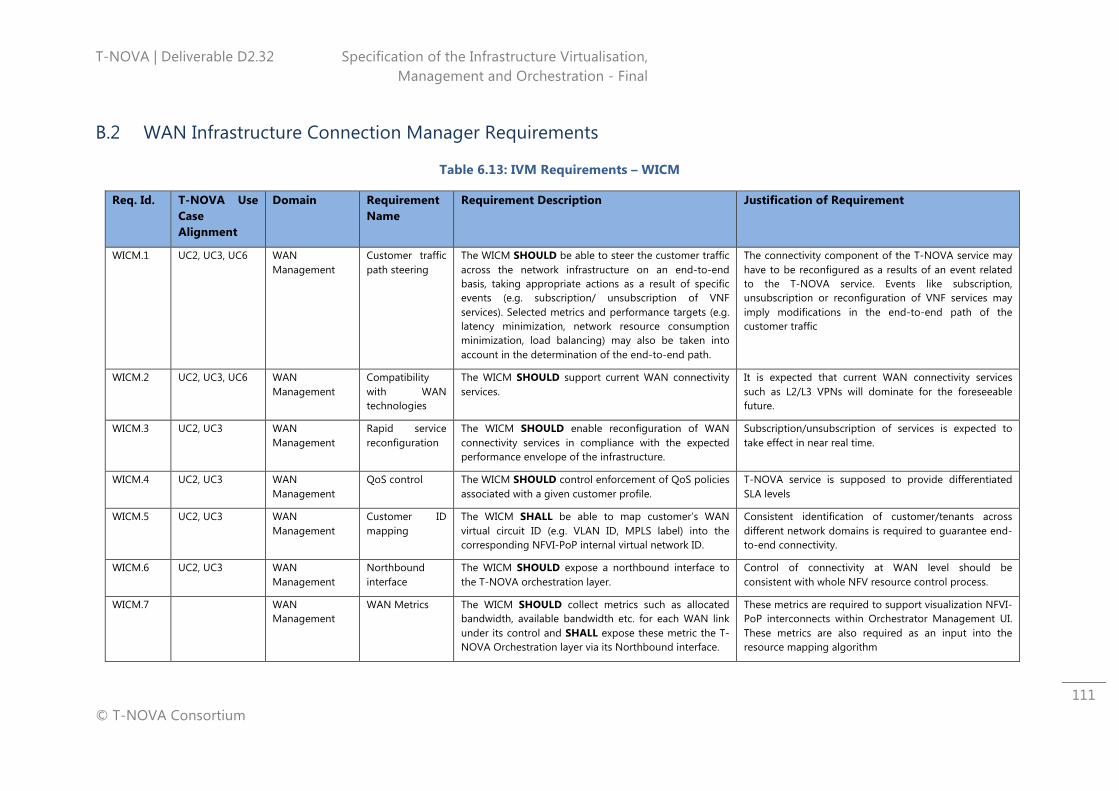
T-NOVA | Deliverable D2.32 Specification of the Infrastructure Virtualisation, Management and Orchestration - Final
© T-NOVA Consortium
111
B.2 WAN Infrastructure Connection Manager Requirements
Table 6.13: IVM Requirements – WICM
Req. Id. T-NOVA Use Case Alignment
Domain Requirement Name
Requirement Description Justification of Requirement
WICM.1 UC2, UC3, UC6 WAN Management
Customer traffic path steering
The WICM SHOULD be able to steer the customer traffic across the network infrastructure on an end-to-end basis, taking appropriate actions as a result of specific events (e.g. subscription/ unsubscription of VNF services). Selected metrics and performance targets (e.g. latency minimization, network resource consumption minimization, load balancing) may also be taken into account in the determination of the end-to-end path.
The connectivity component of the T-NOVA service may have to be reconfigured as a results of an event related to the T-NOVA service. Events like subscription, unsubscription or reconfiguration of VNF services may imply modifications in the end-to-end path of the customer traffic
WICM.2 UC2, UC3, UC6 WAN Management
Compatibility with WAN technologies
The WICM SHOULD support current WAN connectivity services.
It is expected that current WAN connectivity services such as L2/L3 VPNs will dominate for the foreseeable future.
WICM.3 UC2, UC3 WAN Management
Rapid service reconfiguration
The WICM SHOULD enable reconfiguration of WAN connectivity services in compliance with the expected performance envelope of the infrastructure.
Subscription/unsubscription of services is expected to take effect in near real time.
WICM.4 UC2, UC3 WAN Management
QoS control The WICM SHOULD control enforcement of QoS policies associated with a given customer profile.
T-NOVA service is supposed to provide differentiated SLA levels
WICM.5 UC2, UC3 WAN Management
Customer ID mapping
The WICM SHALL be able to map customer’s WAN virtual circuit ID (e.g. VLAN ID, MPLS label) into the corresponding NFVI-PoP internal virtual network ID.
Consistent identification of customer/tenants across different network domains is required to guarantee end-to-end connectivity.
WICM.6 UC2, UC3 WAN Management
Northbound interface
The WICM SHOULD expose a northbound interface to the T-NOVA orchestration layer.
Control of connectivity at WAN level should be consistent with whole NFV resource control process.
WICM.7 WAN Management
WAN Metrics The WICM SHOULD collect metrics such as allocated bandwidth, available bandwidth etc. for each WAN link under its control and SHALL expose these metric the T-NOVA Orchestration layer via its Northbound interface.
These metrics are required to support visualization NFVI-PoP interconnects within Orchestrator Management UI. These metrics are also required as an input into the resource mapping algorithm
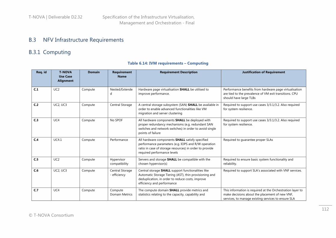
T-NOVA | Deliverable D2.32 Specification of the Infrastructure Virtualisation, Management and Orchestration - Final
© T-NOVA Consortium
112
B.3 NFV Infrastructure Requirements
B.3.1 Computing
Table 6.14: IVM requirements – Computing
Req. id T-NOVA Use Case
Alignment
Domain Requirement Name
Requirement Description Justification of Requirement
C.1 UC2 Compute Nested/Extended
Hardware page virtualisation SHALL be utilised to improve performance.
Performance benefits from hardware page virtualisation are tied to the prevalence of VM exit transitions. CPU should have large TLBs
C.2 UC2, UC3 Compute Central Storage A central storage subsystem (SAN) SHALL be available in order to enable advanced functionalities like VM migration and server clustering
Required to support use cases 3/3.1/3.2. Also required for system resilience.
C.3 UC4 Compute No SPOF All hardware components SHALL be deployed with proper redundancy mechanisms (e.g. redundant SAN switches and network switches) in order to avoid single points of failure
Required to support use cases 3/3.1/3.2. Also required for system resilience.
C.4 UC4.1 Compute Performance All hardware components SHALL satisfy specified performance parameters (e.g. IOPS and R/W operation ratio in case of storage resources) in order to provide required performance levels
Required to guarantee proper SLAs
C.5 UC2 Compute Hypervisor compatibility
Servers and storage SHALL be compatible with the chosen hypervisor(s)
Required to ensure basic system functionality and reliability.
C.6 UC2, UC3 Compute Central Storage - efficiency
Central storage SHALL support functionalities like Automatic Storage Tiering (AST), thin provisioning and deduplication, in order to reduce costs, improve efficiency and performance
Required to support SLA’s associated with VNF services.
C.7 UC4 Compute Compute Domain Metrics
The compute domain SHALL provide metrics and statistics relating to the capacity, capability and
This information is required at the Orchestration layer to make decisions about the placement of new VNF, services, to manage existing services to ensure SLA
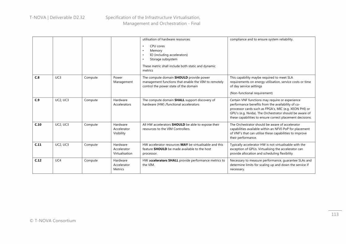
T-NOVA | Deliverable D2.32 Specification of the Infrastructure Virtualisation, Management and Orchestration - Final
© T-NOVA Consortium
113
utilisation of hardware resources:
• CPU cores • Memory • IO (including accelerators) • Storage subsystem
These metric shall include both static and dynamic metrics
compliance and to ensure system reliability.
C.8 UC3 Compute Power Management
The compute domain SHOULD provide power management functions that enable the VIM to remotely control the power state of the domain
This capability maybe required to meet SLA requirements on energy utilisation, service costs or time of day service settings
(Non-functional requirement)
C.9 UC2, UC3 Compute Hardware Accelerators
The compute domain SHALL support discovery of hardware (HW) /functional accelerators
Certain VNF functions may require or experience performance benefits from the availability of co-processor cards such as FPGA’s, MIC (e.g. XEON PHI) or GPU’s (e.g. Nvida). The Orchestrator should be aware of these capabilities to ensure correct placement decisions.
C.10 UC2, UC3 Compute Hardware Accelerator Visibility
All HW accelerators SHOULD be able to expose their resources to the VIM Controllers.
The Orchestrator should be aware of accelerator capabilities available within an NFVI-PoP for placement of VNF’s that can utilise these capabilities to improve their performance.
C.11 UC2, UC3 Compute Hardware Accelerator Virtualisation
HW accelerator resources MAY be virtualisable and this feature SHOULD be made available to the host processor.
Typically accelerator HW is not virtualisable with the exception of GPUs. Virtualising the accelerator can provide allocation and scheduling flexibility
C.12 UC4 Compute Hardware Accelerator Metrics
HW accelerators SHALL provide performance metrics to the VIM.
Necessary to measure performance, guarantee SLAs and determine limits for scaling up and down the service if necessary.
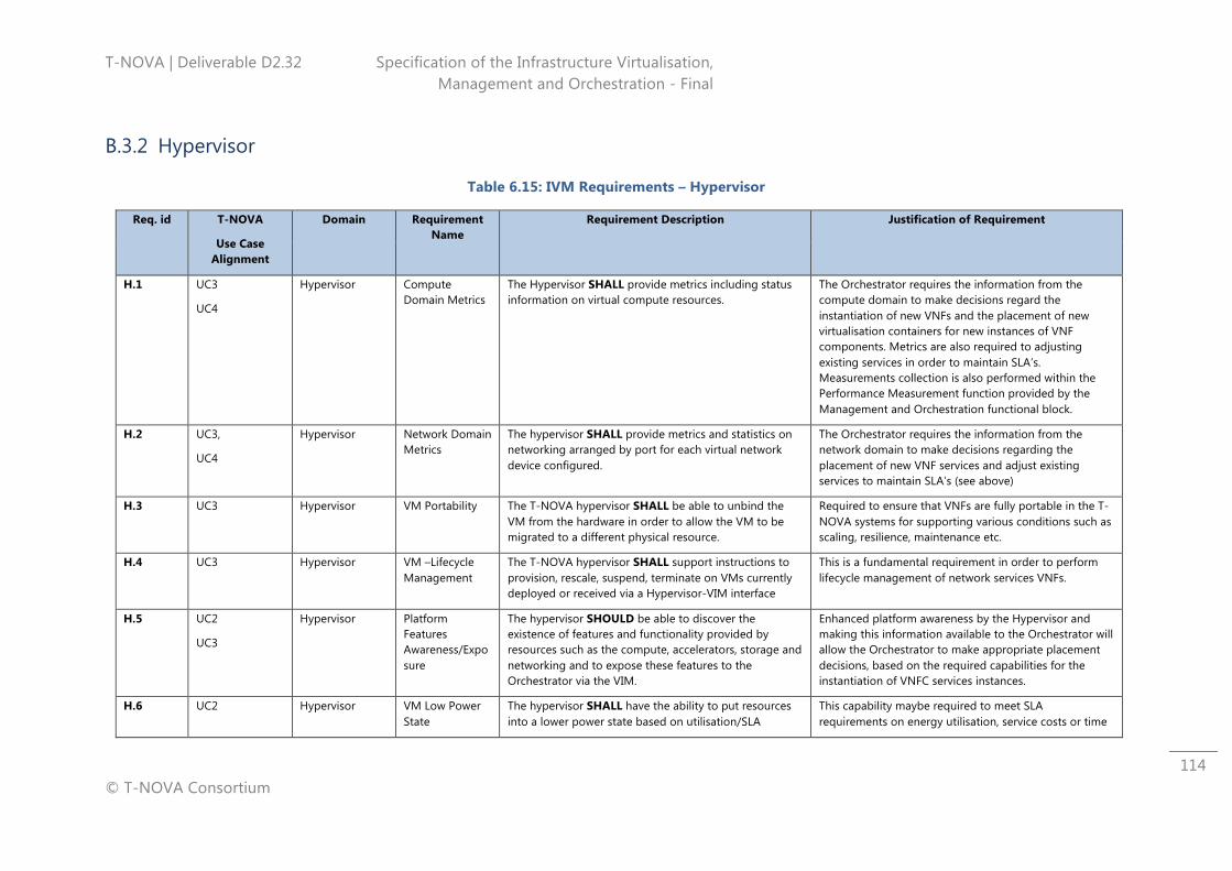
T-NOVA | Deliverable D2.32 Specification of the Infrastructure Virtualisation, Management and Orchestration - Final
© T-NOVA Consortium
114
B.3.2 Hypervisor
Table 6.15: IVM Requirements – Hypervisor
Req. id T-NOVA
Use Case Alignment
Domain Requirement Name
Requirement Description Justification of Requirement
H.1 UC3
UC4
Hypervisor Compute Domain Metrics
The Hypervisor SHALL provide metrics including status information on virtual compute resources.
The Orchestrator requires the information from the compute domain to make decisions regard the instantiation of new VNFs and the placement of new virtualisation containers for new instances of VNF components. Metrics are also required to adjusting existing services in order to maintain SLA’s. Measurements collection is also performed within the Performance Measurement function provided by the Management and Orchestration functional block.
H.2 UC3,
UC4
Hypervisor Network Domain Metrics
The hypervisor SHALL provide metrics and statistics on networking arranged by port for each virtual network device configured.
The Orchestrator requires the information from the network domain to make decisions regarding the placement of new VNF services and adjust existing services to maintain SLA’s (see above)
H.3 UC3 Hypervisor VM Portability The T-NOVA hypervisor SHALL be able to unbind the VM from the hardware in order to allow the VM to be migrated to a different physical resource.
Required to ensure that VNFs are fully portable in the T-NOVA systems for supporting various conditions such as scaling, resilience, maintenance etc.
H.4 UC3 Hypervisor VM –Lifecycle Management
The T-NOVA hypervisor SHALL support instructions to provision, rescale, suspend, terminate on VMs currently deployed or received via a Hypervisor-VIM interface
This is a fundamental requirement in order to perform lifecycle management of network services VNFs.
H.5 UC2
UC3
Hypervisor Platform Features Awareness/Exposure
The hypervisor SHOULD be able to discover the existence of features and functionality provided by resources such as the compute, accelerators, storage and networking and to expose these features to the Orchestrator via the VIM.
Enhanced platform awareness by the Hypervisor and making this information available to the Orchestrator will allow the Orchestrator to make appropriate placement decisions, based on the required capabilities for the instantiation of VNFC services instances.
H.6 UC2 Hypervisor VM Low Power State
The hypervisor SHALL have the ability to put resources into a lower power state based on utilisation/SLA
This capability maybe required to meet SLA requirements on energy utilisation, service costs or time
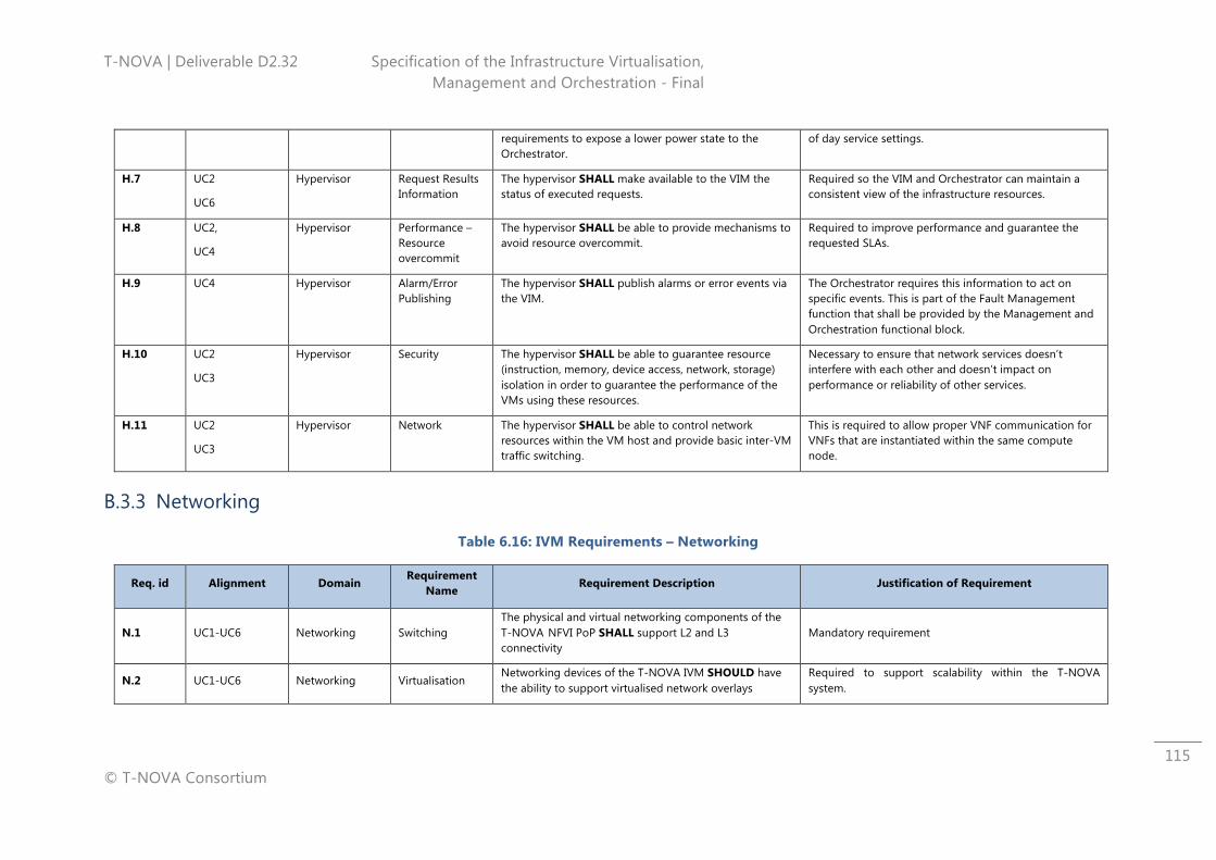
T-NOVA | Deliverable D2.32 Specification of the Infrastructure Virtualisation, Management and Orchestration - Final
© T-NOVA Consortium
115
requirements to expose a lower power state to the Orchestrator.
of day service settings.
H.7 UC2
UC6
Hypervisor Request Results Information
The hypervisor SHALL make available to the VIM the status of executed requests.
Required so the VIM and Orchestrator can maintain a consistent view of the infrastructure resources.
H.8 UC2,
UC4
Hypervisor Performance – Resource overcommit
The hypervisor SHALL be able to provide mechanisms to avoid resource overcommit.
Required to improve performance and guarantee the requested SLAs.
H.9 UC4 Hypervisor Alarm/Error Publishing
The hypervisor SHALL publish alarms or error events via the VIM.
The Orchestrator requires this information to act on specific events. This is part of the Fault Management function that shall be provided by the Management and Orchestration functional block.
H.10 UC2
UC3
Hypervisor Security The hypervisor SHALL be able to guarantee resource (instruction, memory, device access, network, storage) isolation in order to guarantee the performance of the VMs using these resources.
Necessary to ensure that network services doesn’t interfere with each other and doesn’t impact on performance or reliability of other services.
H.11 UC2
UC3
Hypervisor Network The hypervisor SHALL be able to control network resources within the VM host and provide basic inter-VM traffic switching.
This is required to allow proper VNF communication for VNFs that are instantiated within the same compute node.
B.3.3 Networking
Table 6.16: IVM Requirements – Networking
Req. id Alignment Domain Requirement
Name Requirement Description Justification of Requirement
N.1 UC1-UC6 Networking Switching The physical and virtual networking components of the T-NOVA NFVI PoP SHALL support L2 and L3 connectivity
Mandatory requirement
N.2 UC1-UC6 Networking Virtualisation Networking devices of the T-NOVA IVM SHOULD have the ability to support virtualised network overlays
Required to support scalability within the T-NOVA system.
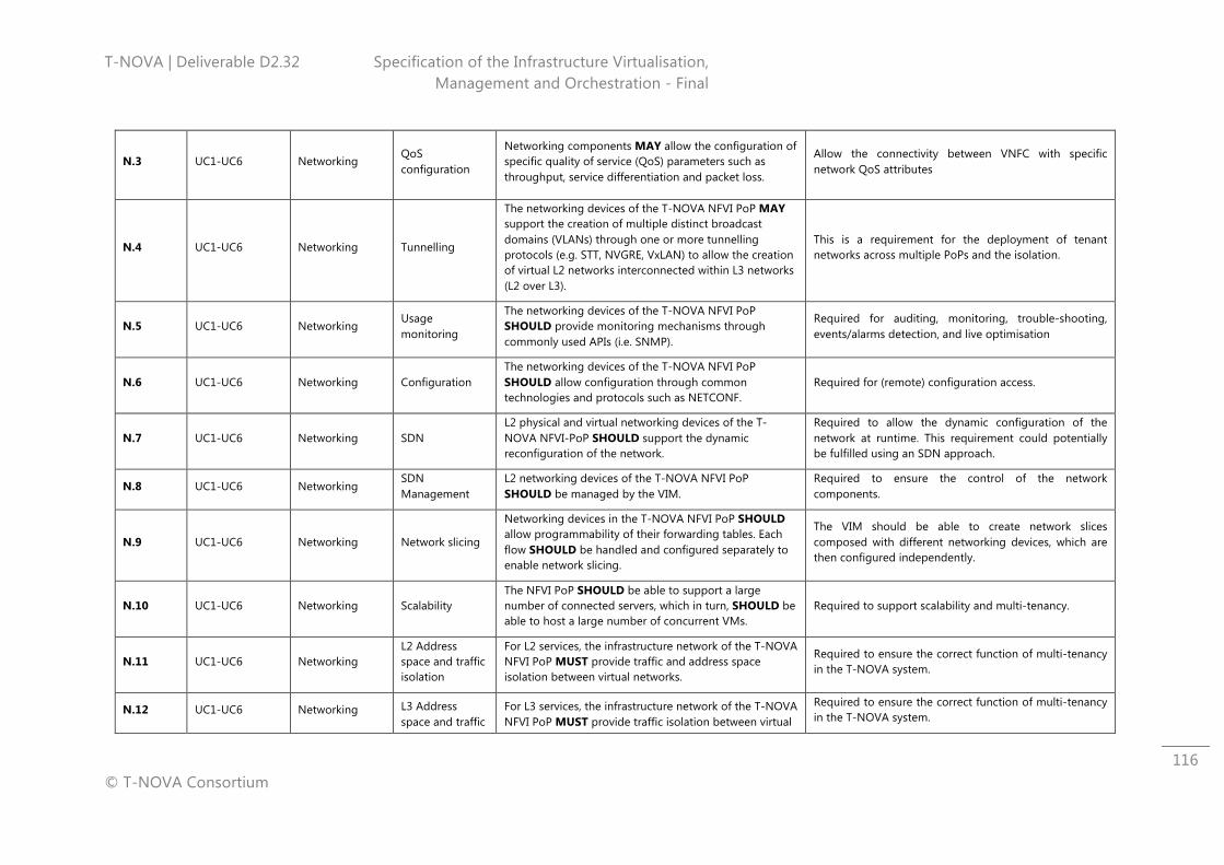
T-NOVA | Deliverable D2.32 Specification of the Infrastructure Virtualisation, Management and Orchestration - Final
© T-NOVA Consortium
116
N.3 UC1-UC6 Networking QoS configuration
Networking components ΜΑΥ allow the configuration of specific quality of service (QoS) parameters such as throughput, service differentiation and packet loss.
Allow the connectivity between VNFC with specific network QoS attributes
N.4 UC1-UC6 Networking Tunnelling
The networking devices of the T-NOVA NFVI PoP ΜΑΥ support the creation of multiple distinct broadcast domains (VLANs) through one or more tunnelling protocols (e.g. STT, NVGRE, VxLAN) to allow the creation of virtual L2 networks interconnected within L3 networks (L2 over L3).
This is a requirement for the deployment of tenant networks across multiple PoPs and the isolation.
N.5 UC1-UC6 Networking Usage monitoring
The networking devices of the T-NOVA NFVI PoP SHOULD provide monitoring mechanisms through commonly used APIs (i.e. SNMP).
Required for auditing, monitoring, trouble-shooting, events/alarms detection, and live optimisation
N.6 UC1-UC6 Networking Configuration The networking devices of the T-NOVA NFVI PoP SHOULD allow configuration through common technologies and protocols such as NETCONF.
Required for (remote) configuration access.
N.7 UC1-UC6 Networking SDN L2 physical and virtual networking devices of the T-NOVA NFVI-PoP SHOULD support the dynamic reconfiguration of the network.
Required to allow the dynamic configuration of the network at runtime. This requirement could potentially be fulfilled using an SDN approach.
N.8 UC1-UC6 Networking SDN Management
L2 networking devices of the T-NOVA NFVI PoP SHOULD be managed by the VIM.
Required to ensure the control of the network components.
N.9 UC1-UC6 Networking Network slicing
Networking devices in the T-NOVA NFVI PoP SHOULD allow programmability of their forwarding tables. Each flow SHOULD be handled and configured separately to enable network slicing.
The VIM should be able to create network slices composed with different networking devices, which are then configured independently.
N.10 UC1-UC6 Networking Scalability The NFVI PoP SHOULD be able to support a large number of connected servers, which in turn, SHOULD be able to host a large number of concurrent VMs.
Required to support scalability and multi-tenancy.
N.11 UC1-UC6 Networking L2 Address space and traffic isolation
For L2 services, the infrastructure network of the T-NOVA NFVI PoP MUST provide traffic and address space isolation between virtual networks.
Required to ensure the correct function of multi-tenancy in the T-NOVA system.
N.12 UC1-UC6 Networking L3 Address space and traffic
For L3 services, the infrastructure network of the T-NOVA NFVI PoP MUST provide traffic isolation between virtual
Required to ensure the correct function of multi-tenancy in the T-NOVA system.
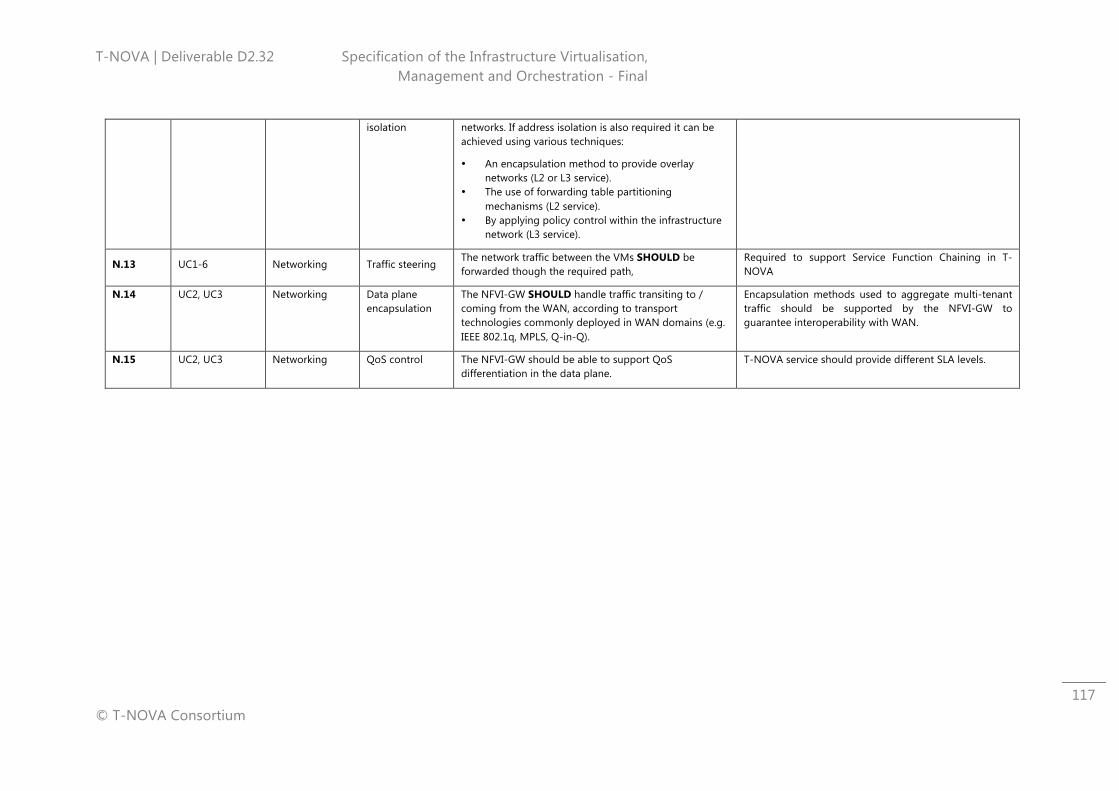
T-NOVA | Deliverable D2.32 Specification of the Infrastructure Virtualisation, Management and Orchestration - Final
© T-NOVA Consortium
117
isolation networks. If address isolation is also required it can be achieved using various techniques:
• An encapsulation method to provide overlay networks (L2 or L3 service).
• The use of forwarding table partitioning mechanisms (L2 service).
• By applying policy control within the infrastructure network (L3 service).
N.13 UC1-6 Networking Traffic steering The network traffic between the VMs SHOULD be forwarded though the required path,
Required to support Service Function Chaining in T-NOVA
N.14 UC2, UC3 Networking Data plane encapsulation
The NFVI-GW SHOULD handle traffic transiting to / coming from the WAN, according to transport technologies commonly deployed in WAN domains (e.g. IEEE 802.1q, MPLS, Q-in-Q).
Encapsulation methods used to aggregate multi-tenant traffic should be supported by the NFVI-GW to guarantee interoperability with WAN.
N.15 UC2, UC3 Networking QoS control The NFVI-GW should be able to support QoS differentiation in the data plane.
T-NOVA service should provide different SLA levels.
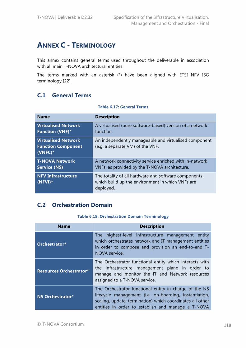
T-NOVA | Deliverable D2.32 Specification of the Infrastructure Virtualisation, Management and Orchestration - Final
© T-NOVA Consortium
118
ANNEX C - TERMINOLOGY
This annex contains general terms used throughout the deliverable in association with all main T-NOVA architectural entities.
The terms marked with an asterisk (*) have been aligned with ETSI NFV ISG terminology [22].
C.1 General Terms
Table 6.17: General Terms
Name Description
Virtualised Network Function (VNF)*
A virtualised (pure software-based) version of a network function.
Virtualised Network Function Component (VNFC)*
An independently manageable and virtualised component (e.g. a separate VM) of the VNF.
T-NOVA Network Service (NS)
A network connectivity service enriched with in-network VNFs, as provided by the T-NOVA architecture.
NFV Infrastructure (NFVI)*
The totality of all hardware and software components which build up the environment in which VNFs are deployed.
C.2 Orchestration Domain
Table 6.18: Orchestration Domain Terminology
Name Description
Orchestrator*
The highest-level infrastructure management entity which orchestrates network and IT management entities in order to compose and provision an end-to-end T-NOVA service.
Resources Orchestrator*
The Orchestrator functional entity which interacts with the infrastructure management plane in order to manage and monitor the IT and Network resources assigned to a T-NOVA service.
NS Orchestrator*
The Orchestrator functional entity in charge of the NS lifecycle management (i.e. on-boarding, instantiation, scaling, update, termination) which coordinates all other entities in order to establish and manage a T-NOVA
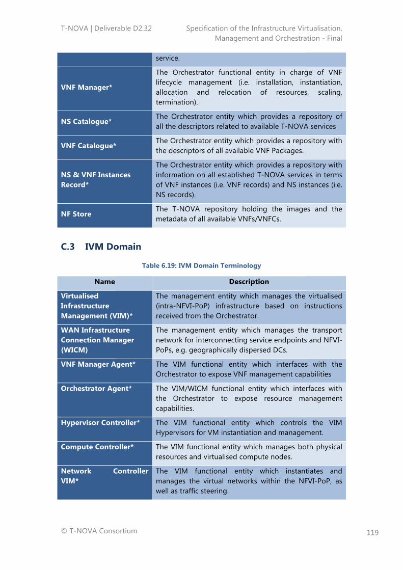
T-NOVA | Deliverable D2.32 Specification of the Infrastructure Virtualisation, Management and Orchestration - Final
© T-NOVA Consortium
119
service.
VNF Manager*
The Orchestrator functional entity in charge of VNF lifecycle management (i.e. installation, instantiation, allocation and relocation of resources, scaling, termination).
NS Catalogue* The Orchestrator entity which provides a repository of all the descriptors related to available T-NOVA services
VNF Catalogue* The Orchestrator entity which provides a repository with the descriptors of all available VNF Packages.
NS & VNF Instances Record*
The Orchestrator entity which provides a repository with information on all established T-NOVA services in terms of VNF instances (i.e. VNF records) and NS instances (i.e. NS records).
NF Store The T-NOVA repository holding the images and the metadata of all available VNFs/VNFCs.
C.3 IVM Domain
Table 6.19: IVM Domain Terminology
Name Description
Virtualised Infrastructure Management (VIM)*
The management entity which manages the virtualised (intra-NFVI-PoP) infrastructure based on instructions received from the Orchestrator.
WAN Infrastructure Connection Manager (WICM)
The management entity which manages the transport network for interconnecting service endpoints and NFVI-PoPs, e.g. geographically dispersed DCs.
VNF Manager Agent* The VIM functional entity which interfaces with the Orchestrator to expose VNF management capabilities
Orchestrator Agent* The VIM/WICM functional entity which interfaces with the Orchestrator to expose resource management capabilities.
Hypervisor Controller* The VIM functional entity which controls the VIM Hypervisors for VM instantiation and management.
Compute Controller* The VIM functional entity which manages both physical resources and virtualised compute nodes.
Network Controller VIM*
The VIM functional entity which instantiates and manages the virtual networks within the NFVI-PoP, as well as traffic steering.
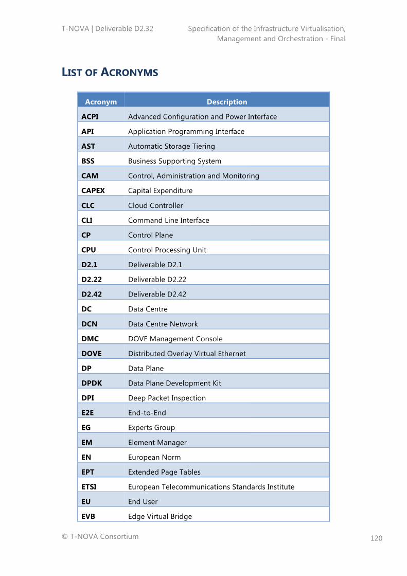
T-NOVA | Deliverable D2.32 Specification of the Infrastructure Virtualisation, Management and Orchestration - Final
© T-NOVA Consortium
120
LIST OF ACRONYMS
Acronym Description
ACPI Advanced Configuration and Power Interface
API Application Programming Interface
AST Automatic Storage Tiering
BSS Business Supporting System
CAM Control, Administration and Monitoring
CAPEX Capital Expenditure
CLC Cloud Controller
CLI Command Line Interface
CP Control Plane
CPU Control Processing Unit
D2.1 Deliverable D2.1
D2.22 Deliverable D2.22
D2.42 Deliverable D2.42
DC Data Centre
DCN Data Centre Network
DMC DOVE Management Console
DOVE Distributed Overlay Virtual Ethernet
DP Data Plane
DPDK Data Plane Development Kit
DPI Deep Packet Inspection
E2E End-to-End
EG Experts Group
EM Element Manager
EN European Norm
EPT Extended Page Tables
ETSI European Telecommunications Standards Institute
EU End User
EVB Edge Virtual Bridge
T-NOVA | Deliverable D2.32 Specification of the Infrastructure Virtualisation, Management and Orchestration - Final
© T-NOVA Consortium
121
FE Functional Entity
FN Future Networks
FP Function Provider
FPGA Field Programmable Gate Array
GS Global Standard
GPU Graphical Processing Unit
GW Gateway
HG Home Gateway
HW Hardware
I/O Input/Output
IaaS Infrastructure as a Service
IEEE Institute of Electrical and Electronics Engineer
IETF Internet Engineering Task Force
INF Infrastructure
IP Internet Protocol
IP Infrastructure Provider
IPAM IP Address Management
IPsec IP security
ISG Industry Specification Group
ISO International Organisation for Standardisation
IT Information Technology
ITU International Telecommunication Union
ITU-T ITU Telecommunication Standardization Sector
IVM Infrastructure Virtualisation and Management
KPI Key Parameter Indicator
L2 Layer 2
L3 Layer 3
LAN Local Area Network
LINP Logically Isolated Network Partition
MAC Mdedia Access Control
MAN Metro Area Network
T-NOVA | Deliverable D2.32 Specification of the Infrastructure Virtualisation, Management and Orchestration - Final
© T-NOVA Consortium
122
MANO Management and Orchestration
MEF Metro Ethernet Forum
MIC Multi-Integrated Cores
MPLS Multiprotocol Label Switching
NaaS Network as a Service
NC Network Controller
NETCONF Network Configuration Protocol
NF Network Function
NFaaS Network Functions-as-a-Service
NFV Network Functions Virtualisation
NFVI Network Functions Virtualisation Infrastructure
NFVIaaS Network Function Virtualisation Infrastructure as-a-Service
NFVI-PoP NFVI-Point of Presence
NFVO Network Function Virtualisation Orchestrator
NG-OSS Next Generation Operations Supporting System
NIC Network Interface Cards
NIP Network Infrastructure Provider
NOC Network Operators Council
NS Network Service
NSD Network Service Descriptor
NV Network Virtualisation
NVGRE Network Virtualisation using Generic Routing Encapsulation
OAN Open Access Network
OCCI Open Cloud Computing Interface
ONF Open Networking Foundation
OPEX Operational Expenditure
OPN Open Platform for NFV
OS Operating System
OSI Open Systems Interconnection
OSS Operations Supporting System
PF Physical Function
T-NOVA | Deliverable D2.32 Specification of the Infrastructure Virtualisation, Management and Orchestration - Final
© T-NOVA Consortium
123
PNF Physical Network Function
PoC Proof of Concept
PC Personal Computer
PER Performance & Portability Best Practices
QPI Quick Path Interconnect
QoS Quality of Service
RAM Random Access Memory
RAS Reliability Availability and Serviceability
REST API Representation State Transfer API
RFC Request for Comments
RPC Remote Procedure Call
RTP Real Time Protocol
SAN Storage Area Network
SBC Session Border Controller
SDN Software-Defined Networking
SDO Standards Development Organisation
SG13 Study Group 13
SLA Service Level Agreement
SNMP Simple Network Management Protocol
SOTA State-Of-The-Art
SP Service Provider
SR-IOV Single Root I/O Virtualisation
SSD Solid-state-disk
STP Spanning Tree Protocol
STT Stateless Transport Tunnelling
SW Software
SWA Software Architecture
ToR Terms of Reference
ToR Top of Rack
TMF TeleManagement Forum
WICM WAN Infrastructure Connection Manager
T-NOVA | Deliverable D2.32 Specification of the Infrastructure Virtualisation, Management and Orchestration - Final
© T-NOVA Consortium
124
TR Technical Report
TS Technical Standard
TSC Technical Steering Committee
T-NOVA Network Functions as-a-Service over Virtualised Infrastructures
UC Use Case
UML Unified Modelling Language
VEB Virtual Edge Bridge
VEPA Virtual Ethernet Port Aggregator
VIM Virtualised Infrastructure Manager
VL Virtual Link
VLD Virtual Link Descriptor
VLAN Virtual Local Area Network
VM Virtual Machine
VMM Virtual Machine Manager
VMX Virtual Machine Extension
VN Virtual Network
VNF Virtual Network Function
VNFC Virtual Network Function Component
VFND Virtual Network Function Descriptor
VNFFG Virtual Network Function Fowarding Graph
VNFFGD Virtual Network Function Fowarding Graph Descriptor
VNFM Virtual Network Function Manager
VRF Virtual Routing and Forwarding
VPN Virtual Private Network
VSAN Virtual Storage Area Network
vNIC Virtual Network Interface Cards
VPN Virtual Private Network
VTN Virtual Tenant Network
WAN Wide Area Network
WG Working Group
WP Work Package
T-NOVA | Deliverable D2.32 Specification of the Infrastructure Virtualisation, Management and Orchestration - Final
© T-NOVA Consortium
125
WP Working Procedures
XML Extended Markup Language
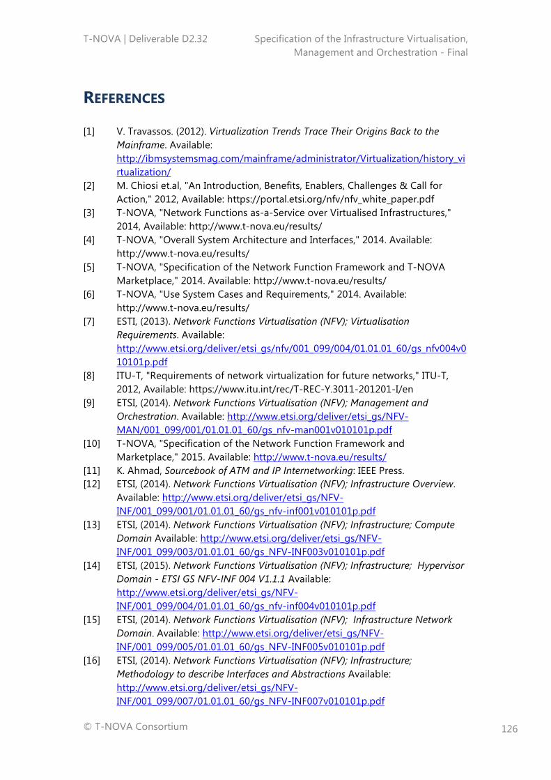
T-NOVA | Deliverable D2.32 Specification of the Infrastructure Virtualisation, Management and Orchestration - Final
© T-NOVA Consortium
126
REFERENCES
[1] V. Travassos. (2012). Virtualization Trends Trace Their Origins Back to the Mainframe. Available: http://ibmsystemsmag.com/mainframe/administrator/Virtualization/history_virtualization/
[2] M. Chiosi et.al, "An Introduction, Benefits, Enablers, Challenges & Call for Action," 2012, Available: https://portal.etsi.org/nfv/nfv_white_paper.pdf
[3] T-NOVA, "Network Functions as-a-Service over Virtualised Infrastructures," 2014, Available: http://www.t-nova.eu/results/
[4] T-NOVA, "Overall System Architecture and Interfaces," 2014. Available: http://www.t-nova.eu/results/
[5] T-NOVA, "Specification of the Network Function Framework and T-NOVA Marketplace," 2014. Available: http://www.t-nova.eu/results/
[6] T-NOVA, "Use System Cases and Requirements," 2014. Available: http://www.t-nova.eu/results/
[7] ESTI, (2013). Network Functions Virtualisation (NFV); Virtualisation Requirements. Available: http://www.etsi.org/deliver/etsi_gs/nfv/001_099/004/01.01.01_60/gs_nfv004v010101p.pdf
[8] ITU-T, "Requirements of network virtualization for future networks," ITU-T, 2012, Available: https://www.itu.int/rec/T-REC-Y.3011-201201-I/en
[9] ETSI, (2014). Network Functions Virtualisation (NFV); Management and Orchestration. Available: http://www.etsi.org/deliver/etsi_gs/NFV-MAN/001_099/001/01.01.01_60/gs_nfv-man001v010101p.pdf
[10] T-NOVA, "Specification of the Network Function Framework and Marketplace," 2015. Available: http://www.t-nova.eu/results/
[11] K. Ahmad, Sourcebook of ATM and IP Internetworking: IEEE Press. [12] ETSI, (2014). Network Functions Virtualisation (NFV); Infrastructure Overview.
Available: http://www.etsi.org/deliver/etsi_gs/NFV-INF/001_099/001/01.01.01_60/gs_nfv-inf001v010101p.pdf
[13] ETSI, (2014). Network Functions Virtualisation (NFV); Infrastructure; Compute Domain Available: http://www.etsi.org/deliver/etsi_gs/NFV-INF/001_099/003/01.01.01_60/gs_NFV-INF003v010101p.pdf
[14] ETSI, (2015). Network Functions Virtualisation (NFV); Infrastructure; Hypervisor Domain - ETSI GS NFV-INF 004 V1.1.1 Available: http://www.etsi.org/deliver/etsi_gs/NFV-INF/001_099/004/01.01.01_60/gs_nfv-inf004v010101p.pdf
[15] ETSI, (2014). Network Functions Virtualisation (NFV); Infrastructure Network Domain. Available: http://www.etsi.org/deliver/etsi_gs/NFV-INF/001_099/005/01.01.01_60/gs_NFV-INF005v010101p.pdf
[16] ETSI, (2014). Network Functions Virtualisation (NFV); Infrastructure; Methodology to describe Interfaces and Abstractions Available: http://www.etsi.org/deliver/etsi_gs/NFV-INF/001_099/007/01.01.01_60/gs_NFV-INF007v010101p.pdf
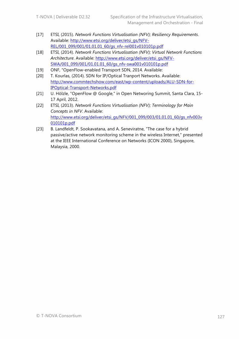
T-NOVA | Deliverable D2.32 Specification of the Infrastructure Virtualisation, Management and Orchestration - Final
© T-NOVA Consortium
127
[17] ETSI, (2015). Network Functions Virtualisation (NFV); Resiliency Requirements. Available: http://www.etsi.org/deliver/etsi_gs/NFV-REL/001_099/001/01.01.01_60/gs_nfv-rel001v010101p.pdf
[18] ETSI, (2014). Network Functions Virtualisation (NFV); Virtual Network Functions Architecture. Available: http://www.etsi.org/deliver/etsi_gs/NFV-SWA/001_099/001/01.01.01_60/gs_nfv-swa001v010101p.pdf
[19] ONF, "OpenFlow-enabled Transport SDN, 2014. Available: [20] T. Kourlas, (2014). SDN for IP/Optical Tranport Networks. Available:
http://www.commtechshow.com/east/wp-content/uploads/ALU-SDN-for-IPOptical-Transport-Networks.pdf
[21] U. Hölzle, "OpenFlow @ Google," in Open Networing Summit, Santa Clara, 15-17 April, 2012.
[22] ETSI, (2013). Network Functions Virtualisation (NFV); Terminology for Main Concepts in NFV. Available: http://www.etsi.org/deliver/etsi_gs/NFV/001_099/003/01.01.01_60/gs_nfv003v010101p.pdf
[23] B. Landfeldt, P. Sookavatana, and A. Seneviratne, "The case for a hybrid passive/active network monitoring scheme in the wireless Internet," presented at the IEEE International Conference on Networks (ICON 2000), Singapore, Malaysia, 2000.