sunguide-utvt-2.0sunguidesoftware.com/sunguidesoftware/.../etc/sunguide-utvt-2.0.1.pdftvt...
TRANSCRIPT
SunGuideTM:
Using SunGuide Travel Times SunGuide-UTVT-2.0.1
Prepared for:
Florida Department of Transportation Traffic Engineering and Operations Office 605 Suwannee Street, M.S. 90 Tallahassee, Florida 32399-0450 (850) 410-5600
January 27, 2009
Using SunGuide Travel Times
SunGuide-UTVT-2.0.1 i
Document Control Panel
File Name: SunGuide-UTVT-2.0.1 File Location: SunGuide CM Repository CDRL: n/a
Name Initial Date
Created By: Steve Dellenback, SwRI SWD 11/14/06
Reviewed By: Robert Heller, SwRI RWH 11/14/06 Trey Tillander, FDOT TT 11/15/06 Steve Dellenback, SwRI SWD 02/09/07 Steve Dellenback, SwRI SWD 02/13/07 Steve Dellenback, SwRI SWD 11/07/08 Steve Dellenback, SwRI SWD 01/16/09 Steve Dellenback, SwRI SWD 01/27/09
Modified By: Steve Dellenback, SwRI SWD 11/14/06 Steve Dellenback, SwRI SWD 11/26/06 Robert Heller, SwRI RWH 01/23/07 Robert Heller, SwRI RWH 02/08/07 Robert Heller, SwRI RWH 02/13/07 Lynne A. Randolph, SwRI LAR 11/07/08 Lynne A. Randolph, SwRI LAR 01/16/09 Lynne A. Randolph, SwRI LAR 01/26/09
Completed By:
Using SunGuide Travel Times
SunGuide-UTVT-2.0.1 ii
Table of Contents
Page List of Tables ................................................................................................................ iv List of Figures .............................................................................................................. iv Revision History ............................................................................................................ v 1. Scope .................................................................................................. 1
1.1 Goal ........................................................................................................... 1 1.2 Overview ................................................................................................... 1 1.3 Travel Time Computation ........................................................................ 1
1.3.1 High Level Discussion of Travel Time Computation ................ 2 1.3.2 Detailed Discussion of Travel Time Computation .................... 3 1.3.3 Differences in TSS Links ........................................................... 4
1.4 TVT Integration with SunGuide .............................................................. 5 1.5 Travel Time Computation Examples ...................................................... 5
1.5.1 Example 1 ................................................................................... 6 1.5.2 Example 2. .................................................................................. 6 1.5.3 Example 3 ................................................................................... 6 1.5.4 Example 4 ................................................................................... 7 1.5.5 Example 5 ................................................................................... 8 1.5.6 Example 6 ................................................................................... 8
2. Using Travel Times ............................................................................ 9
2.1 Configure TVT .......................................................................................... 9 2.2 Add Travel Time Destinations .............................................................. 11 2.3 Create Travel Time Links ...................................................................... 12 2.4 Create Travel Time Message Templates .............................................. 14
2.4.1 Generic Tags ............................................................................ 14 2.4.2 Destination Tags ....................................................................... 14 2.4.3 Grouped Tags ........................................................................... 15 2.4.4 Example Templates .................................................................. 15
2.5 Assigning Templates ............................................................................. 16 2.6 Assign Travel Time Templates / Destination ....................................... 18 2.7 Alternate Routes .................................................................................... 20 2.8 TVT Options ........................................................................................... 21 2.9 Display TvTs on Map ............................................................................. 22 2.10 TVT Archiving ........................................................................................ 24
3. Notes ................................................................................................. 25 4. Frequently Asked Questions (FAQs) ............................................. 26
Using SunGuide Travel Times
SunGuide-UTVT-2.0.1 iii
List of Tables
Page Table 1 Sample Configuration ...................................................................................................... 10 Table 2 Revised Configuration ..................................................................................................... 11 Table 3 Template Examples .......................................................................................................... 15 Table 4 Grouped Template ........................................................................................................... 16
List of Figures
Page Figure 1. Using SunGuide to Generate Travel Time Messages ...................................................... 1 Figure 2. How SunGuide Computes Travel Time Link Speeds ..................................................... 2 Figure 3 Travel Time Link Speeds ................................................................................................. 2 Figure 4. Travel Time Link Definition ........................................................................................... 3 Figure 5. TSS Link Speeds ............................................................................................................. 4 Figure 6. Travel Time Link Calculations ........................................................................................ 4 Figure 7 Link Comparisons ............................................................................................................ 5 Figure 8 Revised Link Comparisons............................................................................................... 5 Figure 9. TVT Destinations .......................................................................................................... 11 Figure 10. TVT Add Destination .................................................................................................. 12 Figure 11. TVT Links ................................................................................................................... 12 Figure 12. Travel Time Links ....................................................................................................... 13 Figure 13. TVT Message Template Listing .................................................................................. 17 Figure 14. Define Message Template ........................................................................................... 18 Figure 15. Sign List....................................................................................................................... 18 Figure 16 Device Templates ......................................................................................................... 19 Figure 17. SunGuide Operator Map – DMS Context Menu ......................................................... 19 Figure 18. Alternate Routes .......................................................................................................... 20 Figure 19.SunGuide Operator Map - TVT Context Menu ........................................................... 21 Figure 20.TVT Administrative Editor Options ............................................................................. 22 Figure 21. Displaying Travel Times on the Map .......................................................................... 23 Figure 22 Travel Time Display ..................................................................................................... 24
Using SunGuide Travel Times
SunGuide-UTVT-2.0.1 iv
List of Acronyms
DMS ...........................Dynamic Message Subsystem FAQ............................Frequently Asked Questions FDOT .........................Florida Department of Transportation GUI ............................Graphical User Interface ITS..............................Intelligent Transportation Systems MAS ...........................Message Arbitration Subsystem SUM ...........................Software Users Manual TSS .............................Transportation Sensor Subsystem TVT ............................Travel Times

Using SunGuide Travel Times
SunGuide-UTVT-2.0.1 v
Revision History Revision Date Changes
1.0.0-Draft November 14, 2006 Initial Release. 1.0.0 November 19, 2006 Updated with FDOT Central Office comments 1.0.1 November 26, 2006 Updated several typographical errors in the document 1.0.2 February 9, 2007 Modifications made:
• Add text to clarify travel time concepts • Updated document with new figures • Corrected typographical errors • Added section 3 containing questions about TVT
calculations and traffic sensors. 1.0.3 February 13, 2007 Modifications made to
• Correct language usage and typos • Correct travel time examples 1, 2 and 4, add
definition of NR as used in the examples. • Remove traffic sensor considerations from section 3. • Reword introductory paragraph of section 3.
2.0.0-Draft November 7, 2008 Updated based on Release 4.1 functionality 2.0.0 January 16, 2009 Updated based on FDOT CO comments 2.0.1 January 27, 2009 Updated based on D6 comments
Using SunGuide Travel Times
SunGuide-UTVT-2.0.1 1
1. Scope
1.1 Goal The goal of this document is to describe how an administrator would configure the Florida Department of Transportation (FDOT) SunGuideTM software to calculate and display travel times (TVT). The reader should refer to the SunGuide Software Users Manual (SUM – see the section titled “Travel Time Editor”), SunGuide Training Material and the SunGuide Version Description Document (VDD – see the section titled “Travel Time”) for additional information.
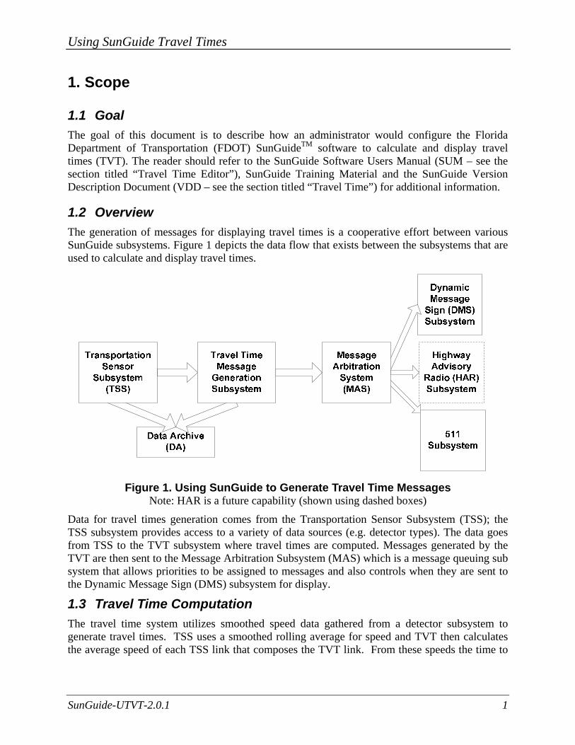
1.2 Overview The generation of messages for displaying travel times is a cooperative effort between various SunGuide subsystems. Figure 1 depicts the data flow that exists between the subsystems that are used to calculate and display travel times.
Figure 1. Using SunGuide to Generate Travel Time Messages
Note: HAR is a future capability (shown using dashed boxes)
Data for travel times generation comes from the Transportation Sensor Subsystem (TSS); the TSS subsystem provides access to a variety of data sources (e.g. detector types). The data goes from TSS to the TVT subsystem where travel times are computed. Messages generated by the TVT are then sent to the Message Arbitration Subsystem (MAS) which is a message queuing sub system that allows priorities to be assigned to messages and also controls when they are sent to the Dynamic Message Sign (DMS) subsystem for display.
1.3 Travel Time Computation The travel time system utilizes smoothed speed data gathered from a detector subsystem to generate travel times. TSS uses a smoothed rolling average for speed and TVT then calculates the average speed of each TSS link that composes the TVT link. From these speeds the time to
Using SunGuide Travel Times
SunGuide-UTVT-2.0.1 2
traverse each TSS link is computed and then the sum of the parts is the travel time over the TVT link.
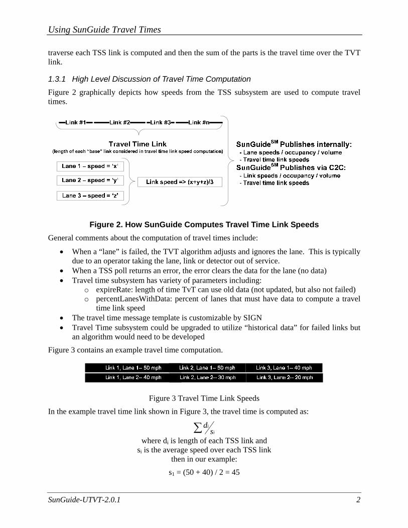
1.3.1 High Level Discussion of Travel Time Computation Figure 2 graphically depicts how speeds from the TSS subsystem are used to compute travel times.
Figure 2. How SunGuide Computes Travel Time Link Speeds General comments about the computation of travel times include:
• When a “lane” is failed, the TVT algorithm adjusts and ignores the lane. This is typically due to an operator taking the lane, link or detector out of service.
• When a TSS poll returns an error, the error clears the data for the lane (no data) • Travel time subsystem has variety of parameters including:
o expireRate: length of time TvT can use old data (not updated, but also not failed) o percentLanesWithData: percent of lanes that must have data to compute a travel
time link speed • The travel time message template is customizable by SIGN • Travel Time subsystem could be upgraded to utilize “historical data” for failed links but
an algorithm would need to be developed
Figure 3 contains an example travel time computation.
Figure 3 Travel Time Link Speeds
In the example travel time link shown in Figure 3, the travel time is computed as:
∑ iis
d
where di is length of each TSS link and si is the average speed over each TSS link
then in our example:
s1 = (50 + 40) / 2 = 45
Using SunGuide Travel Times
SunGuide-UTVT-2.0.1 3
s2 = (50 + 30) / 2 = 40 s3 = (40 + 20) / 2 = 30
d1 = 0.25 miles d2 = 0.50 miles d3 = 0.25 miles
Our travel time is (0.25 / 45) + (0.50 / 40) + (0.25 / 30) = 0.0258 hours or 1.55 minutes
The TVT subsystem can generate travel times message using either the metric system or English system of measurements.
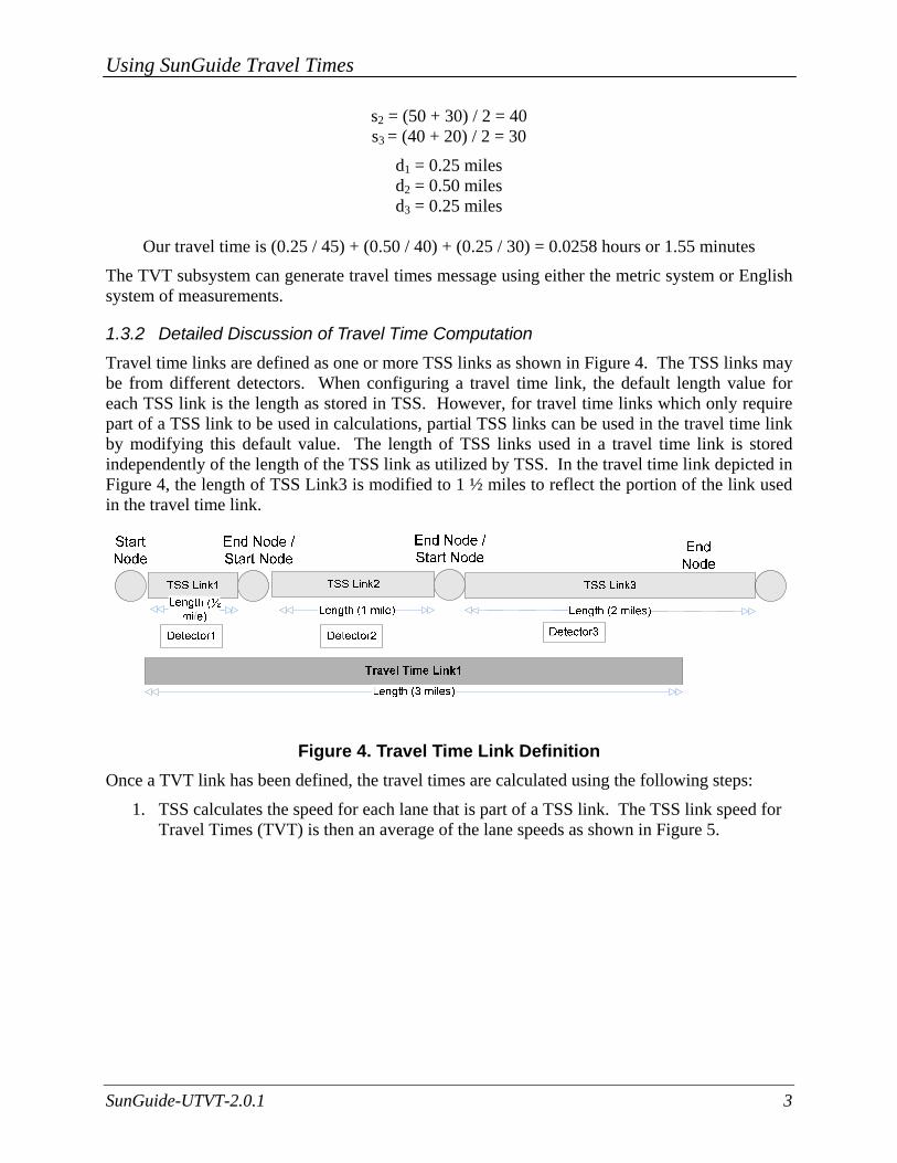
1.3.2 Detailed Discussion of Travel Time Computation Travel time links are defined as one or more TSS links as shown in Figure 4. The TSS links may be from different detectors. When configuring a travel time link, the default length value for each TSS link is the length as stored in TSS. However, for travel time links which only require part of a TSS link to be used in calculations, partial TSS links can be used in the travel time link by modifying this default value. The length of TSS links used in a travel time link is stored independently of the length of the TSS link as utilized by TSS. In the travel time link depicted in Figure 4, the length of TSS Link3 is modified to 1 ½ miles to reflect the portion of the link used in the travel time link.
Figure 4. Travel Time Link Definition Once a TVT link has been defined, the travel times are calculated using the following steps:
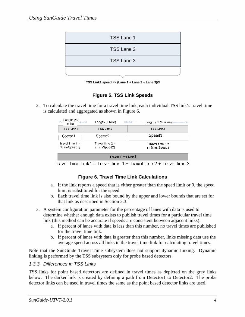
1. TSS calculates the speed for each lane that is part of a TSS link. The TSS link speed for Travel Times (TVT) is then an average of the lane speeds as shown in Figure 5.
Using SunGuide Travel Times
SunGuide-UTVT-2.0.1 4
TSS Lane 1
TSS Lane 2
TSS Lane 3
TSS Link1 speed => (Lane 1 + Lane 2 + Lane 3)/3
Figure 5. TSS Link Speeds
2. To calculate the travel time for a travel time link, each individual TSS link’s travel time is calculated and aggregated as shown in Figure 6.
Figure 6. Travel Time Link Calculations a. If the link reports a speed that is either greater than the speed limit or 0, the speed
limit is substituted for the speed. b. Each travel time link is also bound by the upper and lower bounds that are set for
that link as described in Section 2.3.
3. A system configuration parameter for the percentage of lanes with data is used to determine whether enough data exists to publish travel times for a particular travel time link (this method can be accurate if speeds are consistent between adjacent links):
a. If percent of lanes with data is less than this number, no travel times are published for the travel time link.
b. If percent of lanes with data is greater than this number, links missing data use the average speed across all links in the travel time link for calculating travel times.
Note that the SunGuide Travel Time subsystem does not support dynamic linking. Dynamic linking is performed by the TSS subsystem only for probe based detectors.
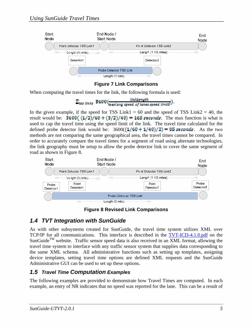
1.3.3 Differences in TSS Links TSS links for point based detectors are defined in travel times as depicted on the grey links below. The darker link is created by defining a path from Detector1 to Detector2. The probe detector links can be used in travel times the same as the point based detector links are used.
Using SunGuide Travel Times
SunGuide-UTVT-2.0.1 5
Figure 7 Link Comparisons
When computing the travel times for the link, the following formula is used:
.
In the given example, if the speed for TSS Link1 = 60 and the speed of TSS Link2 = 40, the result would be: . The max function is what is used to cap the travel time using the speed limit of the link. The travel time calculated for the defined probe detector link would be: 3600( . As the two methods are not comparing the same geographical area, the travel times cannot be compared. In order to accurately compare the travel times for a segment of road using alternate technologies, the link geography must be setup to allow the probe detector link to cover the same segment of road as shown in Figure 8.
Figure 8 Revised Link Comparisons
1.4 TVT Integration with SunGuide As with other subsystems created for SunGuide, the travel time system utilizes XML over TCP/IP for all communications. This interface is described in the TVT-ICD-4.1.0.pdf on the SunGuideTM website. Traffic sensor speed data is also received in an XML format, allowing the travel time system to interface with any traffic sensor system that supplies data corresponding to the same XML schema. All administrative functions such as setting up templates, assigning device templates, setting travel time options are defined XML requests and the SunGuide
Administrative GUI can be used to set up these options.
1.5 Travel Time Computation Examples The following examples are provided to demonstrate how Travel Times are computed. In each example, an entry of NR indicates that no speed was reported for the lane. This can be a result of
Using SunGuide Travel Times
SunGuide-UTVT-2.0.1 6
the data that was last reported has expired (older than expireRate). When no data is reported for a link, the average speed across all links reporting data is used for calculations.
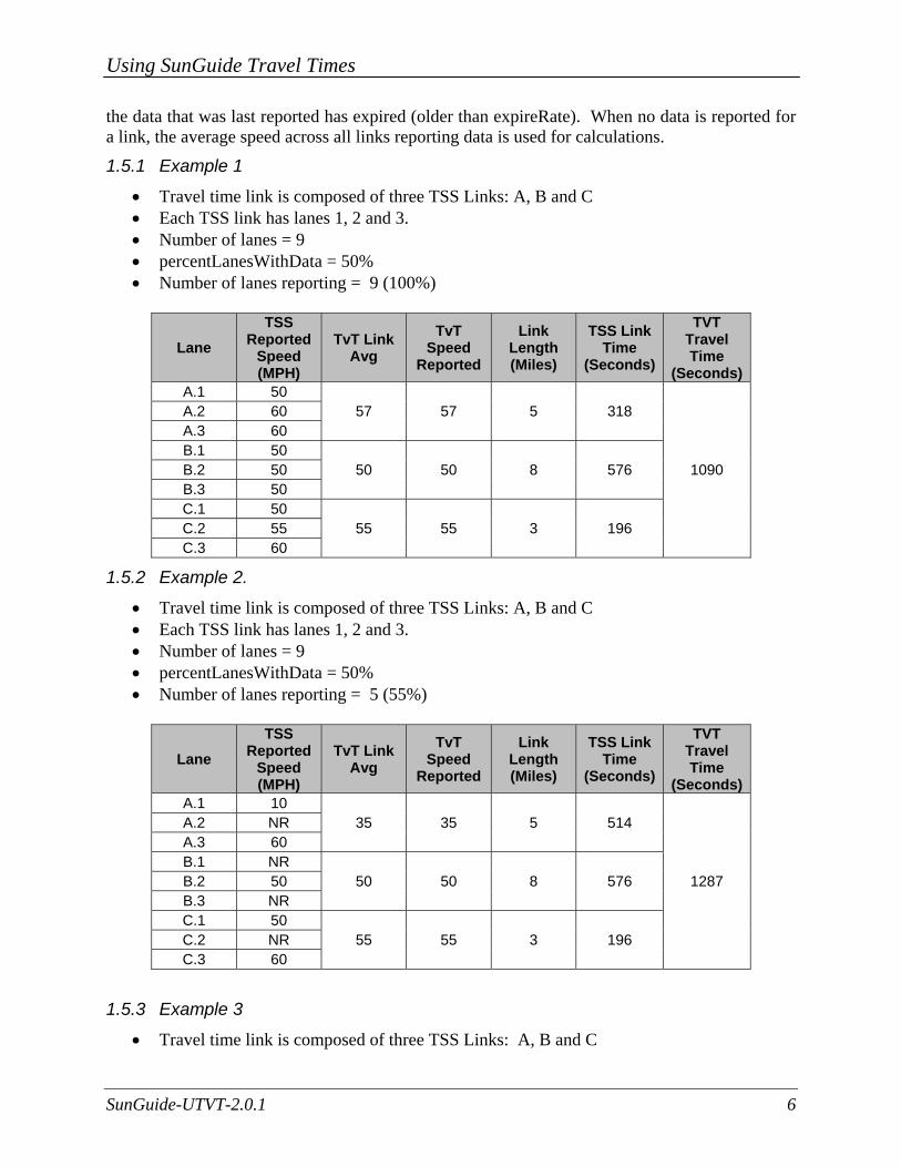
1.5.1 Example 1
• Travel time link is composed of three TSS Links: A, B and C • Each TSS link has lanes 1, 2 and 3. • Number of lanes = 9 • percentLanesWithData = 50% • Number of lanes reporting = 9 (100%)
Lane TSS
Reported Speed (MPH)
TvT Link Avg
TvT Speed
Reported
Link Length (Miles)
TSS Link Time
(Seconds)
TVT Travel Time
(Seconds)A.1 50
57 57 5 318
1090
A.2 60 A.3 60 B.1 50
50 50 8 576 B.2 50 B.3 50 C.1 50
55 55 3 196 C.2 55 C.3 60
1.5.2 Example 2.
• Travel time link is composed of three TSS Links: A, B and C • Each TSS link has lanes 1, 2 and 3. • Number of lanes = 9 • percentLanesWithData = 50% • Number of lanes reporting = 5 (55%)
Lane TSS
Reported Speed (MPH)
TvT Link Avg
TvT Speed
Reported
Link Length (Miles)
TSS Link Time
(Seconds)
TVT Travel Time
(Seconds)A.1 10
35 35 5 514
1287
A.2 NR A.3 60 B.1 NR
50 50 8 576 B.2 50 B.3 NR C.1 50
55 55 3 196 C.2 NR C.3 60
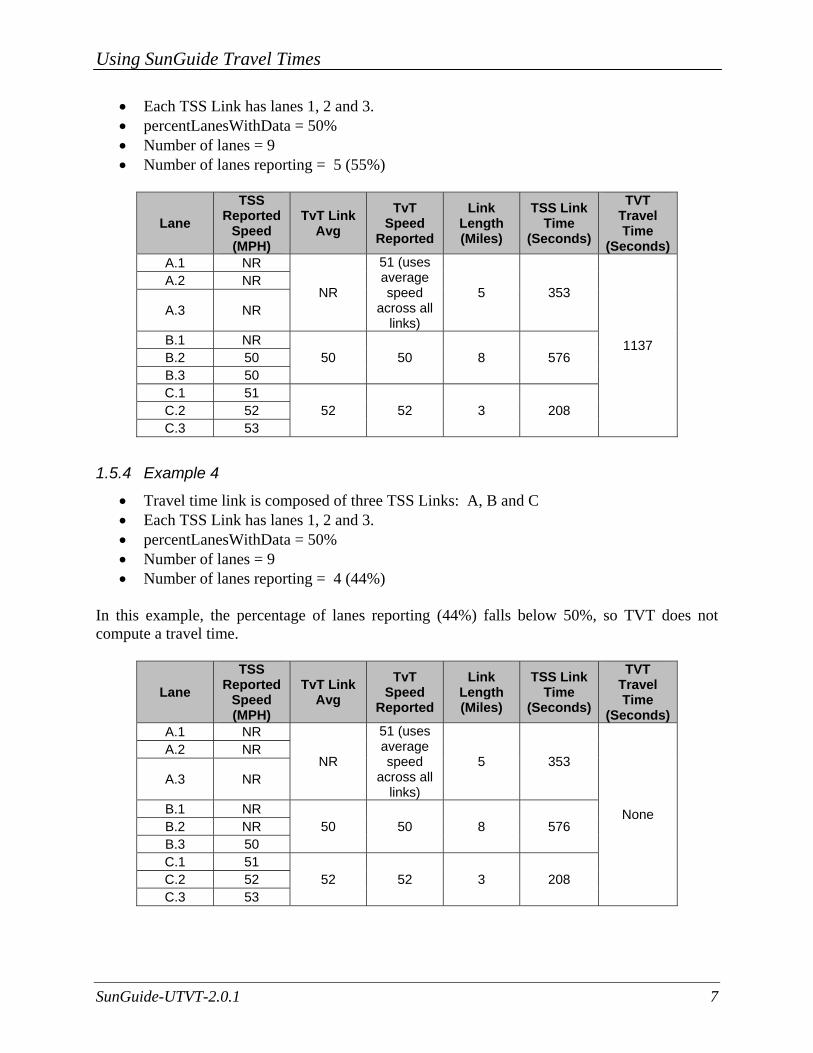
1.5.3 Example 3
• Travel time link is composed of three TSS Links: A, B and C
Using SunGuide Travel Times
SunGuide-UTVT-2.0.1 7
• Each TSS Link has lanes 1, 2 and 3. • percentLanesWithData = 50% • Number of lanes = 9 • Number of lanes reporting = 5 (55%)
Lane TSS
Reported Speed (MPH)
TvT Link Avg
TvT Speed
Reported
Link Length (Miles)
TSS Link Time
(Seconds)
TVT Travel Time
(Seconds)A.1 NR
NR
51 (uses average speed
across all links)
5 353
1137
A.2 NR
A.3 NR
B.1 NR 50 50 8 576 B.2 50
B.3 50 C.1 51
52 52 3 208 C.2 52 C.3 53
1.5.4 Example 4
• Travel time link is composed of three TSS Links: A, B and C • Each TSS Link has lanes 1, 2 and 3. • percentLanesWithData = 50% • Number of lanes = 9 • Number of lanes reporting = 4 (44%)
In this example, the percentage of lanes reporting (44%) falls below 50%, so TVT does not compute a travel time.
Lane TSS
Reported Speed (MPH)
TvT Link Avg
TvT Speed
Reported
Link Length (Miles)
TSS Link Time
(Seconds)
TVT Travel Time
(Seconds)A.1 NR
NR
51 (uses average speed
across all links)
5 353
None
A.2 NR
A.3 NR
B.1 NR 50 50 8 576 B.2 NR
B.3 50 C.1 51
52 52 3 208 C.2 52 C.3 53
Using SunGuide Travel Times
SunGuide-UTVT-2.0.1 8
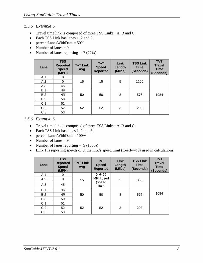
1.5.5 Example 5
• Travel time link is composed of three TSS Links: A, B and C • Each TSS Link has lanes 1, 2 and 3. • percentLanesWithData = 50% • Number of lanes = 9 • Number of lanes reporting = 7 (77%)
Lane TSS
Reported Speed (MPH)
TvT Link Avg
TvT Speed
Reported
Link Length (Miles)
TSS Link Time
(Seconds)
TVT Travel Time
(Seconds)A.1 0
15 15 5 1200
1984
A.2 0 A.3 45 B.1 NR
50 50 8 576 B.2 NR B.3 50 C.1 51
52 52 3 208 C.2 52 C.3 53
1.5.6 Example 6
• Travel time link is composed of three TSS Links: A, B and C • Each TSS Link has lanes 1, 2 and 3. • percentLanesWithData = 100% • Number of lanes = 9 • Number of lanes reporting = 9 (100%) • Link 1 is reporting speeds of 0, the link’s speed limit (freeflow) is used in calculations
Lane TSS
Reported Speed (MPH)
TvT Link Avg
TvT Speed
Reported
Link Length (Miles)
TSS Link Time
(Seconds)
TVT Travel Time
(Seconds)A.1 0
15
0 60 MPH used
(speed limit)
5 300
1084
A.2 0 A.3 45 B.1 NR
50 50 8 576 B.2 NR B.3 50 C.1 51
52 52 3 208 C.2 52 C.3 53
Using SunGuide Travel Times
SunGuide-UTVT-2.0.1 9
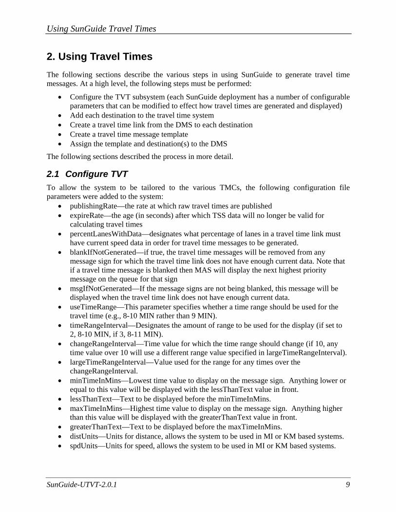
2. Using Travel Times The following sections describe the various steps in using SunGuide to generate travel time messages. At a high level, the following steps must be performed:
• Configure the TVT subsystem (each SunGuide deployment has a number of configurable parameters that can be modified to effect how travel times are generated and displayed)
• Add each destination to the travel time system • Create a travel time link from the DMS to each destination • Create a travel time message template • Assign the template and destination(s) to the DMS
The following sections described the process in more detail.
2.1 Configure TVT To allow the system to be tailored to the various TMCs, the following configuration file parameters were added to the system:
• publishingRate—the rate at which raw travel times are published • expireRate—the age (in seconds) after which TSS data will no longer be valid for
calculating travel times • percentLanesWithData—designates what percentage of lanes in a travel time link must
have current speed data in order for travel time messages to be generated. • blankIfNotGenerated—if true, the travel time messages will be removed from any
message sign for which the travel time link does not have enough current data. Note that if a travel time message is blanked then MAS will display the next highest priority message on the queue for that sign
• msgIfNotGenerated—If the message signs are not being blanked, this message will be displayed when the travel time link does not have enough current data.
• useTimeRange—This parameter specifies whether a time range should be used for the travel time (e.g., 8-10 MIN rather than 9 MIN).
• timeRangeInterval—Designates the amount of range to be used for the display (if set to 2, 8-10 MIN, if 3, 8-11 MIN).
• changeRangeInterval—Time value for which the time range should change (if 10, any time value over 10 will use a different range value specified in largeTimeRangeInterval).
• largeTimeRangeInterval—Value used for the range for any times over the changeRangeInterval.
• minTimeInMins—Lowest time value to display on the message sign. Anything lower or equal to this value will be displayed with the lessThanText value in front.
• lessThanText—Text to be displayed before the minTimeInMins. • maxTimeInMins—Highest time value to display on the message sign. Anything higher
than this value will be displayed with the greaterThanText value in front. • greaterThanText—Text to be displayed before the maxTimeInMins. • distUnits—Units for distance, allows the system to be used in MI or KM based systems. • spdUnits—Units for speed, allows the system to be used in MI or KM based systems.
Using SunGuide Travel Times
SunGuide-UTVT-2.0.1 10
• minUnits—Units for minutes text, allows the system to create travel time messages in a different language than English.
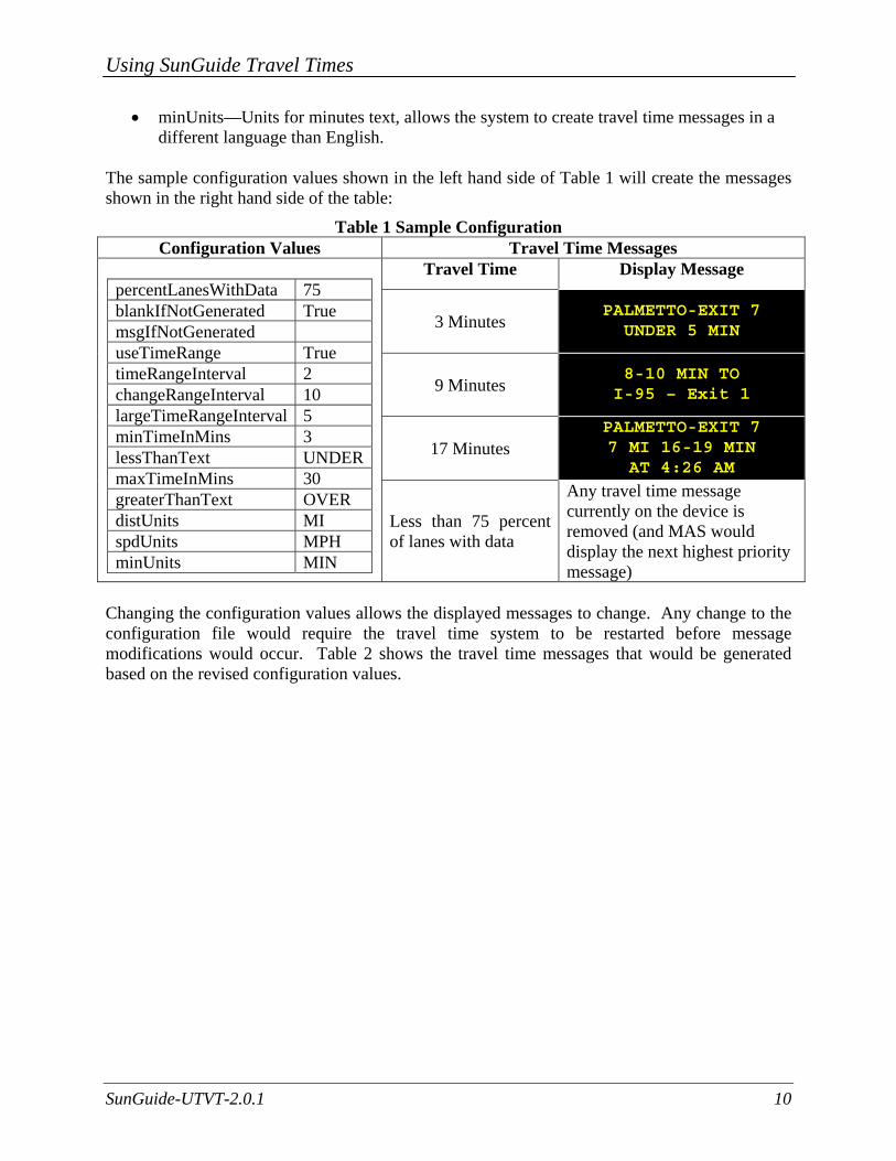
The sample configuration values shown in the left hand side of Table 1 will create the messages shown in the right hand side of the table:
Table 1 Sample Configuration Configuration Values Travel Time Messages
percentLanesWithData 75 blankIfNotGenerated True msgIfNotGenerated useTimeRange True timeRangeInterval 2 changeRangeInterval 10 largeTimeRangeInterval 5 minTimeInMins 3 lessThanText UNDER maxTimeInMins 30 greaterThanText OVER distUnits MI spdUnits MPH minUnits MIN
Travel Time Display Message
3 Minutes PALMETTO-EXIT 7 UNDER 5 MIN
9 Minutes 8-10 MIN TO I-95 – Exit 1
17 Minutes PALMETTO-EXIT 7 7 MI 16-19 MIN AT 4:26 AM
Less than 75 percent of lanes with data
Any travel time message currently on the device is removed (and MAS would display the next highest priority message)
Changing the configuration values allows the displayed messages to change. Any change to the configuration file would require the travel time system to be restarted before message modifications would occur. Table 2 shows the travel time messages that would be generated based on the revised configuration values.

Using SunGuide Travel Times
SunGuide-UTVT-2.0.1 11
Table 2 Revised Configuration Configuration Values Travel Time Messages
percentLanesWithData 75 blankIfNotGenerated false msgIfNotGenerated [pt30o0][jl3]
Travel Time[nl] Unknown
useTimeRange true timeRangeInterval 3 changeRangeInterval 10 largeTimeRangeInterval 5 minTimeInMins 3 lessThanText < maxTimeInMins 15 greaterThanText > distUnits MI spdUnits MPH minUnits MIN
Travel Time Display Message
3 Minutes PALMETTO-EXIT 7 UNDER 3 MIN
9 Minutes 8-11 MIN TO I-95 – EXIT 1
17 Minutes PALMETTO-EXIT 7 7 MI >15 MIN AT 4:26 AM
Less than 75 percent of lanes with data
TRAVEL TIME UNKNOWN
2.2 Add Travel Time Destinations The TVT Destinations Editor enables the administrator to manage TVT destinations (tags that are used in the generation of travel time messages). These destination names are the actual text displayed on a DMS when a travel time message is generated containing a destination tag. NOTE: Destination names must be valid approved words to prevent spelling conflicts. Destinations may be entered using a simple text field as shown in Figure 9. These are provided primarily to save duplicate data when the same destination is used for multiple devices.
Figure 9. TVT Destinations
Using SunGuide Travel Times
SunGuide-UTVT-2.0.1 12
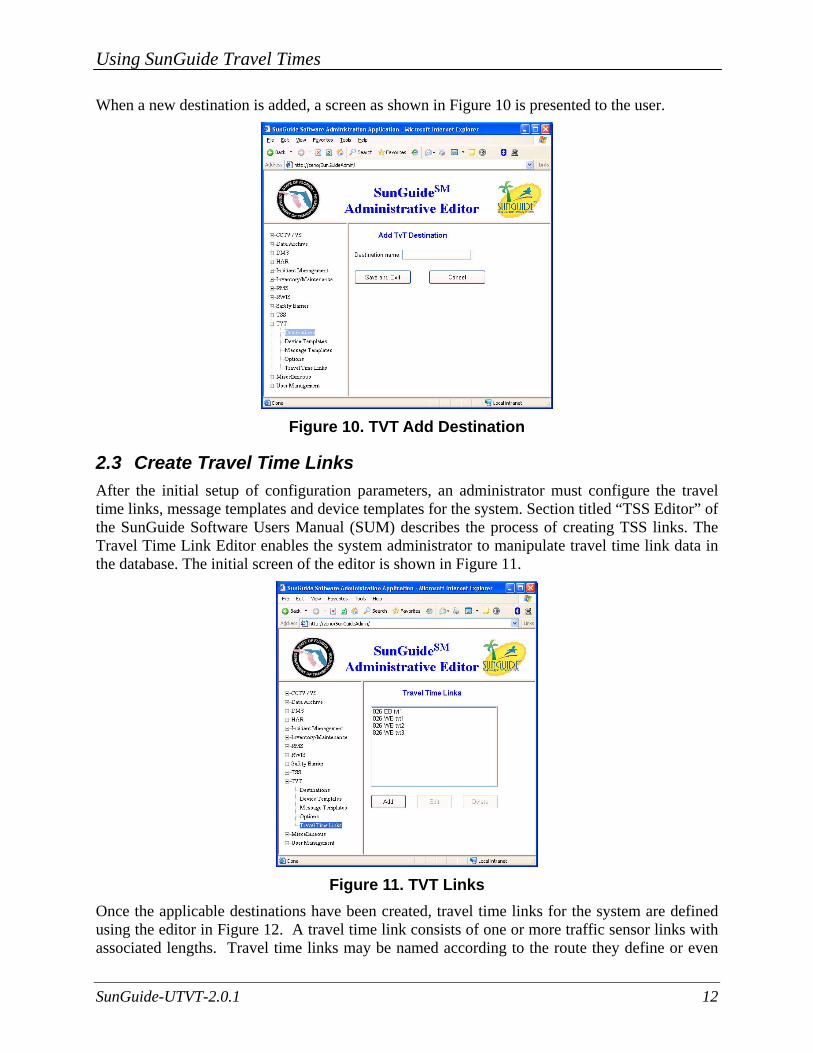
When a new destination is added, a screen as shown in Figure 10 is presented to the user.
Figure 10. TVT Add Destination
2.3 Create Travel Time Links After the initial setup of configuration parameters, an administrator must configure the travel time links, message templates and device templates for the system. Section titled “TSS Editor” of the SunGuide Software Users Manual (SUM) describes the process of creating TSS links. The Travel Time Link Editor enables the system administrator to manipulate travel time link data in the database. The initial screen of the editor is shown in Figure 11.
Figure 11. TVT Links
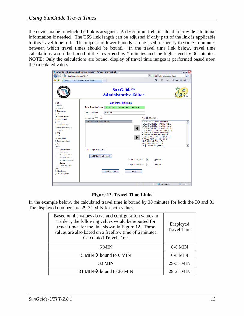
Once the applicable destinations have been created, travel time links for the system are defined using the editor in Figure 12. A travel time link consists of one or more traffic sensor links with associated lengths. Travel time links may be named according to the route they define or even
Using SunGuide Travel Times
SunGuide-UTVT-2.0.1 13
the device name to which the link is assigned. A description field is added to provide additional information if needed. The TSS link length can be adjusted if only part of the link is applicable to this travel time link. The upper and lower bounds can be used to specify the time in minutes between which travel times should be bound. In the travel time link below, travel time calculations would be bound at the lower end by 7 minutes and the higher end by 30 minutes. NOTE: Only the calculations are bound, display of travel time ranges is performed based upon the calculated value.
Figure 12. Travel Time Links In the example below, the calculated travel time is bound by 30 minutes for both the 30 and 31. The displayed numbers are 29-31 MIN for both values.
Based on the values above and configuration values in Table 1, the following values would be reported for travel times for the link shown in Figure 12. These
values are also based on a freeflow time of 6 minutes. Calculated Travel Time
Displayed Travel Time
6 MIN 6-8 MIN
5 MIN bound to 6 MIN 6-8 MIN
30 MIN 29-31 MIN
31 MIN bound to 30 MIN 29-31 MIN
Using SunGuide Travel Times
SunGuide-UTVT-2.0.1 14
2.4 Create Travel Time Message Templates In addition to the configuration parameters available in the system, message templates are used to specify the format of the display on a message sign. When a message template is created, a name and a number of destinations are associated with the template. Depending upon the number of destinations, several formatting tags are available.
2.4.1 Generic Tags Generic tags are general tags which are not tied to a particular travel time link or destination. The available generic tags are as follows:
• FreeText—Allows for any text to be created for the template. For instance, “TRAVEL TIME TO” or “AT”.
• [NEW LINE]—Forces the display to place a new line character in the message, displaying subsequent text on the next lower line of the DMS.
• [NEW PAGE]—Forces the display to place a new page character in the message, all text following this character should display on the next page of the DMS.
• [SPACE]—Adds a space between two tags (normally, spaces are included in free text sections, but a single space at the beginning or end of free text may not render).
• [TIME]—Adds the current time (from the system running travel times) to the message.
2.4.2 Destination Tags Other tags are specifically related to a destination. Travel time templates can be configured to allow a specific number of travel time links to display information. Each of the following tags is associated to one of those links based on the number at the end of the tag. For instance, [DEST1] would apply to the first travel time link, while [DEST2] would apply to the second. In the tag names below, the trailing “x” should be replaced by the appropriate link number.
• [STARTx] – Indicates the start of a section of the travel time message related to a particular travel time link. (Discussed in detail below.)
• [DESTx] – Replaced with the name of the destination (e.g., PALMETTO-EXIT 7) associated to the travel time link in the device template.
• [TVTx] – Replaced with the current travel time of the travel time link, in minutes. This usually is displayed as a range with a suffix, such as “6-8 MINS”. The range and suffix are specified in the configuration file, described in Section 2.1.
• [SPEEDx] – Replaced with the current average speed of the travel time link, in miles per hour.
• [DISTx] – Replaced with the length of the travel time link, in miles. • [ENDx] – Indicates the end of a section of a travel time message related to a particular
travel time link.
Using SunGuide Travel Times
SunGuide-UTVT-2.0.1 15
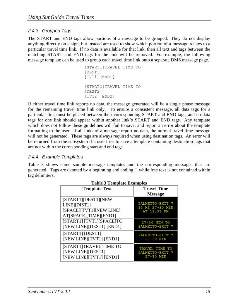
2.4.3 Grouped Tags The START and END tags allow portions of a message to be grouped. They do not display anything directly on a sign, but instead are used to show which portion of a message relates to a particular travel time link. If no data is available for that link, then all text and tags between the matching START and END tags for the link will be removed. For example, the following message template can be used to group each travel time link onto a separate DMS message page.
[START1]TRAVEL TIME TO [DEST1] [TVT1][END1] [START2]TRAVEL TIME TO [DEST2] [TVT2][END2]
If either travel time link reports no data, the message generated will be a single phase message for the remaining travel time link only. To ensure a consistent message, all data tags for a particular link must be placed between their corresponding START and END tags, and no data tags for one link should appear within another link’s START and END tags. Any template which does not follow these guidelines will fail to save, and report an error about the template formatting to the user. If all links of a message report no data, the normal travel time message will not be generated. These tags are always required when using destination tags. An error will be returned from the subsystem if a user tries to save a template containing destination tags that are not within the corresponding start and end tags.
2.4.4 Example Templates Table 3 shows some sample message templates and the corresponding messages that are generated. Tags are denoted by a beginning and ending [] while free text is not contained within tag delimiters.
Table 3 Template Examples Template Text Travel Time
Message [START1][DEST1][NEW LINE][DIST1] [SPACE][TVT1][NEW LINE] AT[SPACE][TIME][END1]
PALMETTO-EXIT 7 15 MI 27-30 MIN AT 12:31 PM
[START1] [TVT1][SPACE]TO [NEW LINE][DEST1] [END1]
27-30 MIN TO PALMETTO-EXIT 7
[START1] [DEST1] [NEW LINE][TVT1] [END1]
PALMETTO-EXIT 7 27-30 MIN
[START1]TRAVEL TIME TO [NEW LINE][DEST1] [NEW LINE][TVT1] [END1]
TRAVEL TIME TO PALMETTO-EXIT 7
27-30 MIN
Using SunGuide Travel Times
SunGuide-UTVT-2.0.1 16
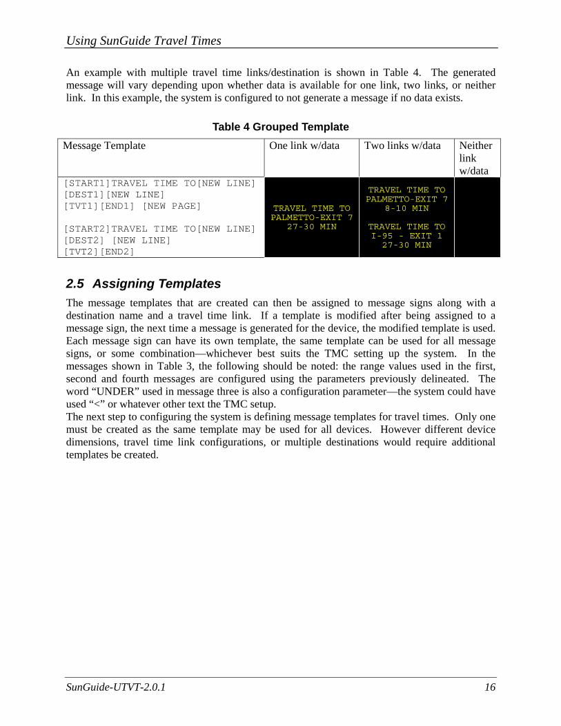
An example with multiple travel time links/destination is shown in Table 4. The generated message will vary depending upon whether data is available for one link, two links, or neither link. In this example, the system is configured to not generate a message if no data exists.
Table 4 Grouped Template Message Template One link w/data Two links w/data Neither
link w/data
[START1]TRAVEL TIME TO[NEW LINE][DEST1][NEW LINE] [TVT1][END1] [NEW PAGE] [START2]TRAVEL TIME TO[NEW LINE] [DEST2] [NEW LINE] [TVT2][END2]
TRAVEL TIME TO PALMETTO-EXIT 7
27-30 MIN
TRAVEL TIME TO PALMETTO-EXIT 7
8-10 MIN
TRAVEL TIME TO I-95 - EXIT 1 27-30 MIN
2.5 Assigning Templates The message templates that are created can then be assigned to message signs along with a destination name and a travel time link. If a template is modified after being assigned to a message sign, the next time a message is generated for the device, the modified template is used. Each message sign can have its own template, the same template can be used for all message signs, or some combination—whichever best suits the TMC setting up the system. In the messages shown in Table 3, the following should be noted: the range values used in the first, second and fourth messages are configured using the parameters previously delineated. The word “UNDER” used in message three is also a configuration parameter—the system could have used “<” or whatever other text the TMC setup. The next step to configuring the system is defining message templates for travel times. Only one must be created as the same template may be used for all devices. However different device dimensions, travel time link configurations, or multiple destinations would require additional templates be created.
Using SunGuide Travel Times
SunGuide-UTVT-2.0.1 17
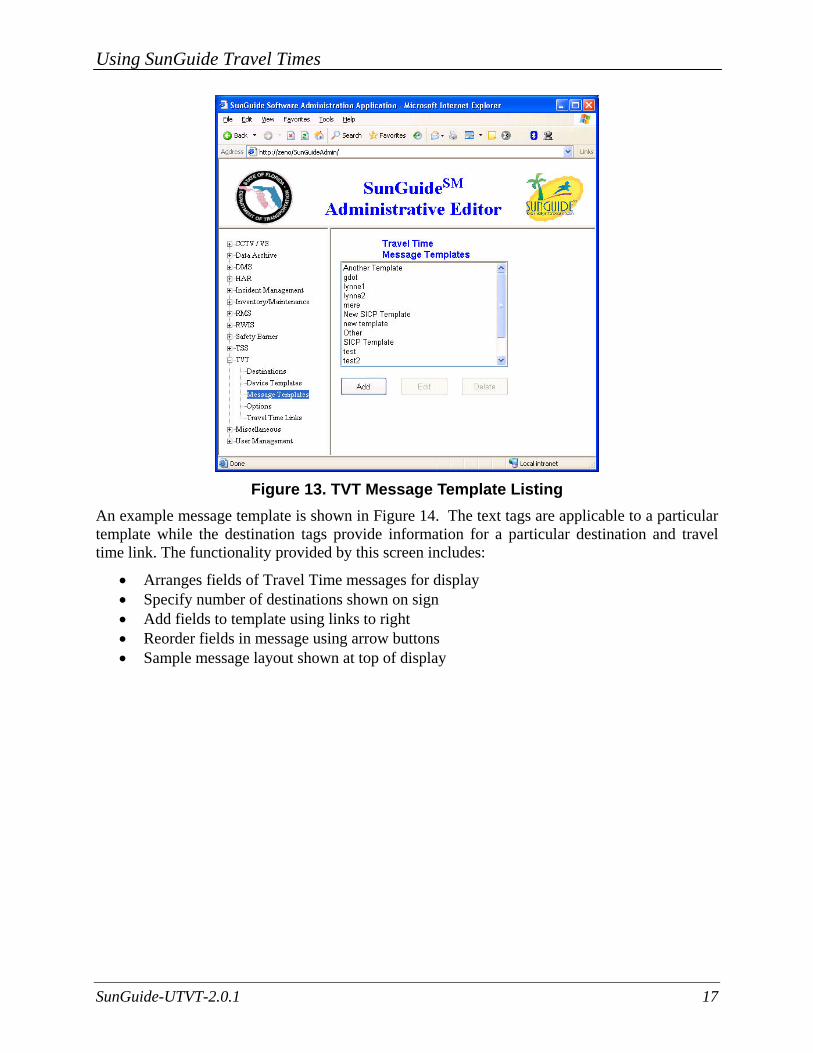
Figure 13. TVT Message Template Listing
An example message template is shown in Figure 14. The text tags are applicable to a particular template while the destination tags provide information for a particular destination and travel time link. The functionality provided by this screen includes:
• Arranges fields of Travel Time messages for display • Specify number of destinations shown on sign • Add fields to template using links to right • Reorder fields in message using arrow buttons • Sample message layout shown at top of display

Using SunGuide Travel Times
SunGuide-UTVT-2.0.1 18
Figure 14. Define Message Template
2.6 Assign Travel Time Templates / Destination The next step is to assign a message template to a device. The first step is to select a sign and then a template must be assigned to the sign. The selection of a sign is depicted in Figure 15.
Figure 15. Sign List
Once a sign is selected, the screen to select a template is displayed as shown in Figure 16. For each destination, a travel time link is selected to provide data. If device templates and message templates are modified while the system is running, the travel time messages generated are updated accordingly.

Using SunGuide Travel Times
SunGuide-UTVT-2.0.1 19
Figure 16 Device Templates
For each device, travel times may be enabled or disabled for a particular DMS either during initial setup or as a separate request as shown in Figure 17.
Figure 17. SunGuide Operator Map – DMS Context Menu
Using SunGuide Travel Times
SunGuide-UTVT-2.0.1 20
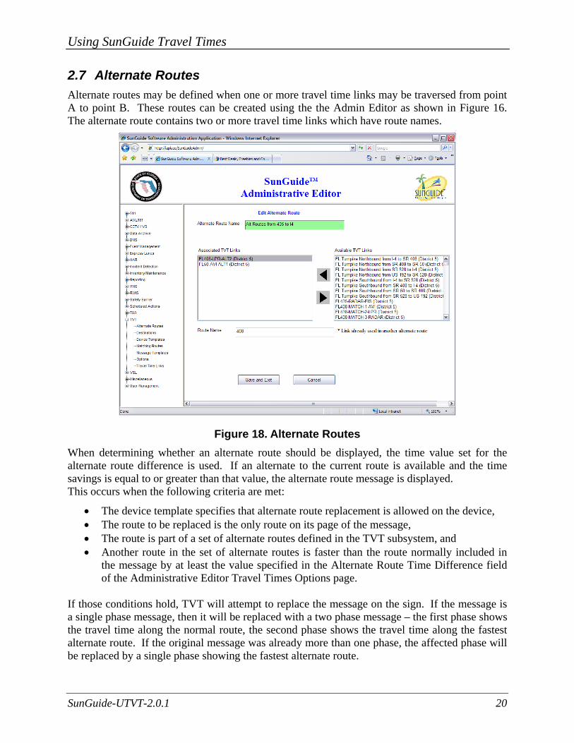
2.7 Alternate Routes Alternate routes may be defined when one or more travel time links may be traversed from point A to point B. These routes can be created using the the Admin Editor as shown in Figure 16. The alternate route contains two or more travel time links which have route names.
Figure 18. Alternate Routes When determining whether an alternate route should be displayed, the time value set for the alternate route difference is used. If an alternate to the current route is available and the time savings is equal to or greater than that value, the alternate route message is displayed. This occurs when the following criteria are met:
• The device template specifies that alternate route replacement is allowed on the device, • The route to be replaced is the only route on its page of the message, • The route is part of a set of alternate routes defined in the TVT subsystem, and • Another route in the set of alternate routes is faster than the route normally included in
the message by at least the value specified in the Alternate Route Time Difference field of the Administrative Editor Travel Times Options page.
If those conditions hold, TVT will attempt to replace the message on the sign. If the message is a single phase message, then it will be replaced with a two phase message – the first phase shows the travel time along the normal route, the second phase shows the travel time along the fastest alternate route. If the original message was already more than one phase, the affected phase will be replaced by a single phase showing the fastest alternate route.
Using SunGuide Travel Times
SunGuide-UTVT-2.0.1 21
The subsystem will first attempt to use the following template to format each message: TO [DEST] VIA [ROUTE] [DIST] [TVT]
If the message does not fit using this template, an alternate template will be attempted:
TO [DEST] VIA [ROUTE][DIST] [TVT]
For a message which was originally more than one phase, if neither message fits, the original travel time message will be displayed. For a message which was originally one phase, if either new phase would not fit, the original travel time message will be displayed. In either of these cases, an alert will be broadcast to any currently logged in users to indicate that the alternate route configuration failed to generate a valid message.
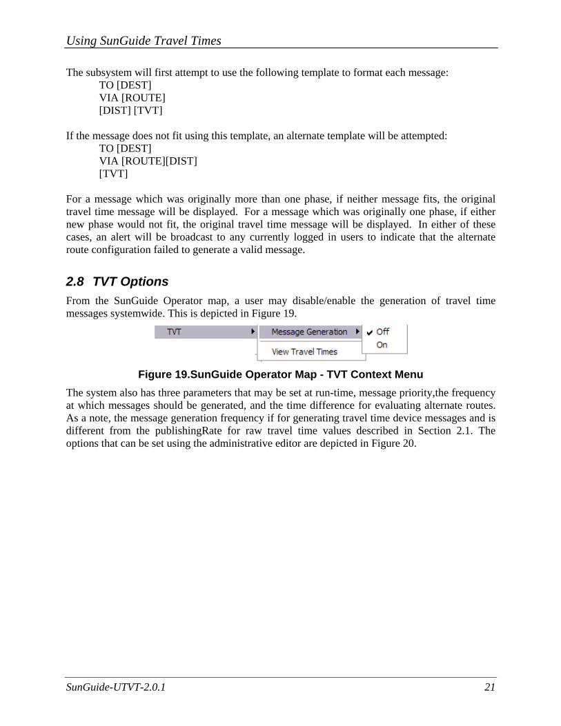
2.8 TVT Options From the SunGuide Operator map, a user may disable/enable the generation of travel time messages systemwide. This is depicted in Figure 19.
Figure 19.SunGuide Operator Map - TVT Context Menu
The system also has three parameters that may be set at run-time, message priority,the frequency at which messages should be generated, and the time difference for evaluating alternate routes. As a note, the message generation frequency if for generating travel time device messages and is different from the publishingRate for raw travel time values described in Section 2.1. The options that can be set using the administrative editor are depicted in Figure 20.

Using SunGuide Travel Times
SunGuide-UTVT-2.0.1 22
Figure 20.TVT Administrative Editor Options
2.9 Display TvTs on Map When travel times are being generated by the SunGuide system, an operator may wish to view the travel times being generated on the operator map. Figure 21 displays the travel times currently generated by the system. Links for which valid travel times are not being generated will not have values in the current/freeflow/delay columns. Any travel time links which are not generating travel times will report a travel time of -1 or unavailable. Any travel time messages relying on that link will not be generated.
Using SunGuide Travel Times
SunGuide-UTVT-2.0.1 23
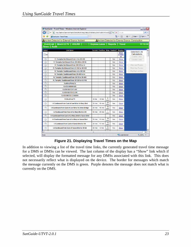
Figure 21. Displaying Travel Times on the Map
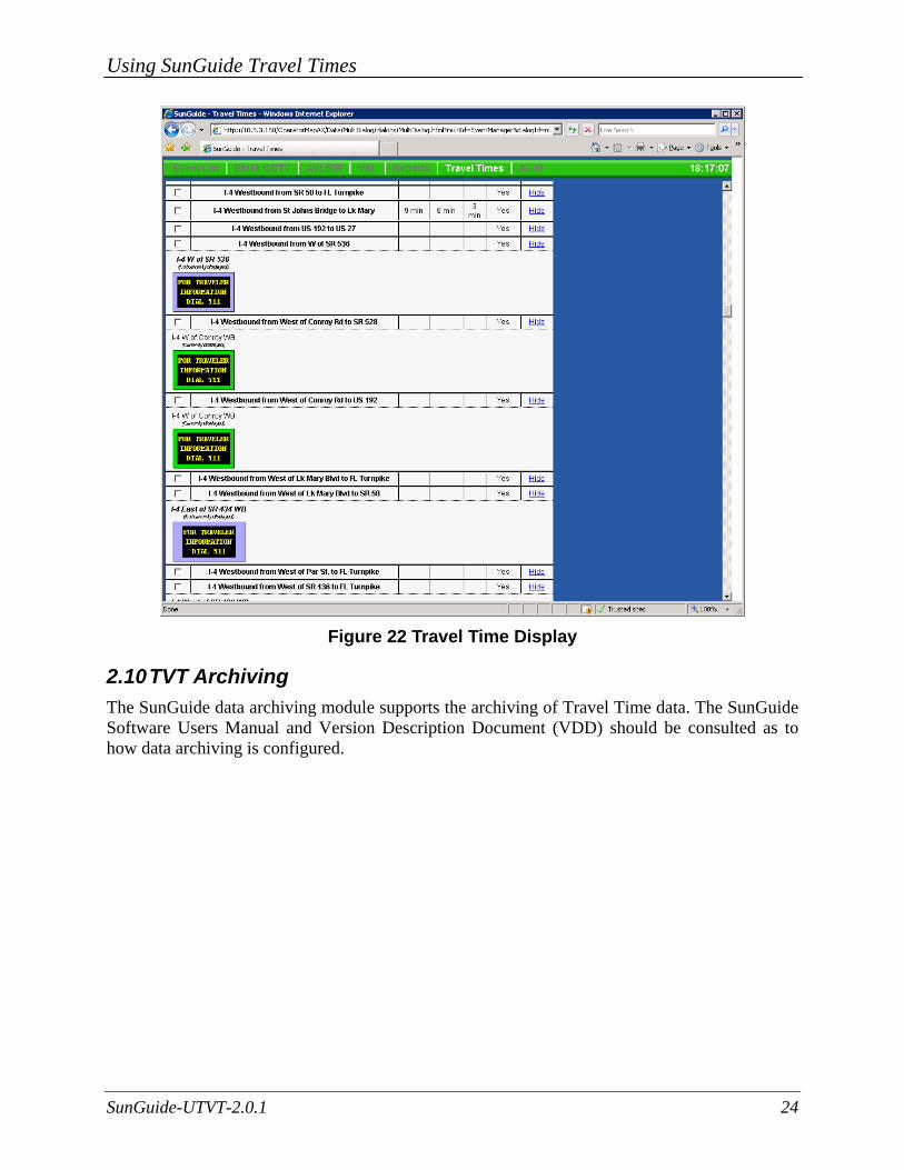
In addition to viewing a list of the travel time links, the currently generated travel time message for a DMS or DMSs can be viewed. The last column of the display has a “Show” link which if selected, will display the formatted message for any DMSs associated with this link. This does not necessarily reflect what is displayed on the device. The border for messages which match the message currently on the DMS is green. Purple denotes the message does not match what is currently on the DMS.
Using SunGuide Travel Times
SunGuide-UTVT-2.0.1 24
Figure 22 Travel Time Display
2.10 TVT Archiving The SunGuide data archiving module supports the archiving of Travel Time data. The SunGuide Software Users Manual and Version Description Document (VDD) should be consulted as to how data archiving is configured.

Using SunGuide Travel Times
SunGuide-UTVT-2.0.1 25
3. Notes The following are insight/observations that have been made about the SunGuide Travel Time subsystem since it was developed and deployed:
• During system testing, travel time messages for different routes were generated every thirty seconds for twenty-five Dynamic Message Signs (DMS). The test system was utilizing two servers, each having dual 3.2 GHz CPUs and 2 Gigabytes of RAM. The Oracle database was running on a third server, also 3.2 GHz with 4 Gigabytes of RAM. The travel time system consumed 38MB of RAM and less than 10% of the CPU processing cycles. The generation of travel times was performed by a software process independent of the process that posting the messages to the DMS devices. The generation of travel times is an extremely efficient process that can create several hundred messages in less than a second once the detector data is available to the process. In SunGuide, the travel time process submits the recommended messages to a DMS queue manager that subsequently posts messages to each sign. Messages can be posted in less than three seconds for directly connected signs while dial-up signs experience a longer post time. The DMS subsystem is capable of posting on average at least ten messages every second to different DMS devices.
• When a travel time is computed for a TSS link, if the computed speed for links are above the configured speed limit (each link has a speed limit entered in the Administrative Editor) then the computed speed will be lowered to the configured speed limit. This will ensure that travel times that are above the speed limits will not be generated.
• During testing of Travel Times in District 2, the District personnel set the priority of the travel times to be low; they then generated a blank message for each sign that had a priority higher than the travel time’s priority. This allowed the District personnel to review the travel times in MAS but since the blank message had a higher priority they were not displayed to the traveling public. This process allowed a “quality assurance” check to be performed on the validity of the travel times computed.
Using SunGuide Travel Times
SunGuide-UTVT-2.0.1 26
4. Frequently Asked Questions (FAQs) The follow Frequently Asked Questions (FAQs) are often asked about SunGuide Travel Times:
1. Is the timestamp in the data archive csv file the time recorded by the detector in the field, the time received by the SunGuide software or the time when the system archive the data?
a. If the timestamp is in the data received for the lane and can be parsed correctly, that date is used. If not, the time received by the data archive process is used.
2. What is the meaning of smooth rolling average for speed data? Does the software average the past few readings or use smoothing equations? How many time steps in the past are used in this smoothing?
a. The rolling average takes the readings received during the previous n seconds. When a reading is older than the current time – n seconds, it is no longer used. The number of readings used depends upon the average period, which is configurable (avgPeriod in the TSS portion of the configuration file), and the polling frequency of the detector (which can be set per detector).
3. What is the time step to calculate the travel time? (the period that the SunGuide aggregates the 20-second data to when calculating travel time).
a. The travel times process uses the smoothed speed from TSS (see answer to question 2) when calculating a travel time. The most recently calculated smoothed speed is used when travel times are generated. Travel times are generated on a configurable frequency (publishingRate in the configuration file).
4. When estimating travel time, does the SunGuide software have a filtering mechanism such as excluding the zero speed or unusually high speeds?
a. Travel times uses smoothed TSS data. When smoothing TSS data, the speeds are capped by the speed limit set for the link. If the speed for the link is 0, 0 is averaged in unless both the volume and the occupancy are also 0.
5. Our sign only displays freeflow time as a travel time even though we know speeds are varying?
a. If the upper bound is less than the freeflow time, the sign could show the freeflow travel time when not expected. This configuration should be modified so the upper bound is greater than freeflow time.