sunguide-ip-d1fm-1.0sunguidesoftware.com/.../deployments/sunguide-ip-d1fm-1.0.2.pdf · 2.3.2...
TRANSCRIPT

SunGuideTM: Implementation Plan for District 1 Ft. Myers SunGuide-IP-D1FM-1.0.2
Prepared for: Florida Department of Transportation Traffic Engineering and Operations Office 605 Suwannee Street, M.S. 90 Tallahassee, Florida 32399-0450 (850) 410-5600 November 21, 2008

Implementation Plan
SunGuide-IP-D1FM-1.0.2 i
Document Control Panel
File Name: SunGuide-IP-D1FM-1.0.2 File Location: SunGuide CM Repository CDRL: 7-8
Name Initial Date
Created By: Steve Dellenback, SwRI SWD 11/05/08 Reviewed By: Steve Dellenback, SwRI SWD 11/05/08
Steve Dellenback, SwRI SWD 11/12/08 Steve Dellenback, SwRI SWD 11/20/08 Steve Dellenback, SwRI SWD 11/21/08
Modified By: Clay Packard, SwRI CP 11/07/08 Adam Clauss, SwRI ASC 11/07/08 Hector Iruegas, SwRI HI 11/07/08 Steve Dellenback, SwRI SWD 11/12/08 Steve Dellenback, SwRI SWD 11/20/08 Steve Dellenback, SwRI SWD 11/21/08
Completed By:

Implementation Plan
SunGuide-IP-D1FM-1.0.2 ii
Table of Contents
Page List of Acronyms ......................................................................................................... iii Revision History .......................................................................................................... iv
1. Scope ................................................................................................. 1 1.1 Document Identification .......................................................................... 1 1.2 Project Overview ...................................................................................... 1 1.3 Related Documents ................................................................................. 2 1.4 Contacts ................................................................................................... 2
2. Deployment Details........................................................................... 3
2.1 Subsystems To Be Installed ................................................................... 3 2.2 District 1: Before Software Installation .................................................. 3
2.2.1 Servers ........................................................................................ 4 2.2.2 Workstations .............................................................................. 8 2.2.3 Device Protocol Compliance ..................................................... 8 2.2.4 Network Infrastructure ............................................................... 9 2.2.5 Device Worksheets .................................................................. 11
2.3 SwRI: Software Installation ................................................................... 17 2.3.1 Server Preparation .................................................................... 17 2.3.2 Workstation Preparation .......................................................... 17 2.3.3 Software Installation ................................................................ 17 2.3.4 Software Configuration ............................................................ 18 2.3.5 C2C Configuration ................................................................... 18
2.4 SwRI / D1FM: Post Software Installation (Configuration) ................... 19 2.4.1 Populate Tables ........................................................................ 19 2.4.2 Create Map Links ..................................................................... 20 2.4.3 DMS Linking File .................................................................... 20
2.5 SwRI / D1FM: Testing ............................................................................ 20 2.6 Training ................................................................................................... 21 2.7 Deployment Schedule ........................................................................... 23
3. Notes ................................................................................................ 24 Appendicies: A – Current device Listing

Implementation Plan
SunGuide-IP-D1FM-1.0.2 iii
List of Acronyms
C2C ...........................Center-to-Center CCTV .......................Closed Circuit Television ConOps .....................Concept of Operations CSE ...........................Computer Sizing Estimates DMS .........................Dynamic Message Sign EH .............................Executive Handler EM ............................Event Management FDOT ........................Florida Department of Transportation GUI ...........................Graphical User Interface IDS ............................Incident Detection Systen IIS .............................Internet Information Server IP ..............................Implementation Plan ITS ............................Intelligent Transportation Systems IV&V ........................Independent Verification and Validation MCP ..........................Manual Control Panel NTCIP ......................National Transportation Communications for ITS Protocol RMS ..........................Ramp Metering Subsystem RPG ..........................Response Plan Generator RS .............................Reporting Subsystem RTMC .......................Regional Traffic Management Center RWIS ........................Roadway Weather Information System SB .............................Safety Barrier SDD ..........................Software Design Document SICP ..........................Software Integration Case Procedures SIP ............................Software Integration Plan SRS ...........................Software Requirements Specification SUM .........................Software User’s Manual SwRI .........................Southwest Research Institute TCP/IP ......................Transmission Control Protocol/Internet Protocol TMC .........................Transportation Management Center TS .............................Terminal Server TSS ...........................Transportation Sensor Subsystem TvT ...........................Travel Time VDD .........................Version Description Document VPN ..........................Virtual Private Network

Implementation Plan
SunGuide-IP-D1FM-1.0.2 iv
REVISION HISTORY
Revision Date Changes
1.0.0-Draft November 7, 2008 Initial Release 1.0.0 November 12, 2008 Updated based on District 1 comments. 1.0.1 November 20, 2008 Updated based on TransCore comments. 1.0.2 November 21, 2008 Updated with graphics provided by TransCore.

Implementation Plan
SunGuide-IP-D1FM-1.0.2 1
1. Scope 1.1 Document Identification This document serves as the Implementation Plan (IP) for the SunGuideTM software specific to the District 1, Ft. Myers implementation (D1FM).
1.2 Project Overview The Florida Department of Transportation (FDOT) is conducting a program that is developing SunGuide software. The SunGuide software is a set of Intelligent Transportation System (ITS) software that allows the control of roadway devices as well as information exchange across a variety of transportation agencies. The goal of the SunGuide software is to have a common software base that can be deployed throughout the state of Florida. The SunGuide software development effort was based on ITS software available from the state of Texas. In addition to the reuse of software (along with customization of this software), a number of new software modules are being developed. The following figure provides a graphical view of the software.
Figure 1.1 - High-Level Architectural Concept
The SunGuide development effort began in October 2003, two major releases have been developed and this document is addressing the third major release of the software. After the development, the software will be deployed to a number of Districts and Expressway Authorities throughout Florida and support activities will be performed.

Implementation Plan
SunGuide-IP-D1FM-1.0.2 2
1.3 Related Documents A number of documents are available on the project web site that describe the SunGuide software. Many of these documents were used to produce this document. The “Reading Room” of the project web site should be reviewed:
http://sunguide.datasys.swri.edu
1.4 Contacts The following are contact persons for the SunGuide software project:
Elizabeth Birriel, ITS Central Office, [email protected], 850-410-5606 Trey Tillander, FDOT SunGuide Project Manager, [email protected], 850-
410-5617 David Chang, ITS Specialist, [email protected], 850-410-5622 Steve Dellenback, SwRI Project Manager, [email protected], 210-522-3914 Robert Heller, SwRI Software Project Manager, [email protected], 210-522-3824
The following are contacts for other organizations that are expected to be involved with this deployment:
Florida Department of Transportation, District 1 ITS
o Carlos Bonilla, Operations Manager, [email protected], (239) 461-4338
o Chris R. Birosak, ITS Program Manager, [email protected], (863) 519-2507
o Katherine Duvall, ITS Project Manager, [email protected], (863) 519-2726
Consultants:
o Arturo Espinosa, ITS Systems Engineer, [email protected], 954.342.0690
o Roger Marrero, [email protected] o Julio Natareno, [email protected]

Implementation Plan
SunGuide-IP-D1FM-1.0.2 3
2. Deployment Details The following documents should be available to District 1 staff as they prepare for a SunGuide deployment (the most recent versions are available on the project web site):
• Computer Sizing Estimates (CSE) • Software Requirements Specification (SRS) • Software Design Document (SDD) • Version Description Document (VDD) • Software User’s Manual (SUM) • Software Integration Plan (SIP) • Software Integration Case Procedures (SICP) • Administrator Training Slides • Operator Training Slides • Installation Notes
2.1 Subsystems To Be Installed The following Release 4.1 SunGuide subsystems will be installed for the initial deployment at District 1:
• Administrative Editor (AE) • Center-to-Center (C2C) - note: access to FLATIS Floodgate capability and sending
events to FLATIS is implemented as part of the C2C plug-ins • Closed Circuit Television (CCTV) • Data Bus (DB) • Data Archive (DA) • Dynamic Message Sign (DMS) • Event Management (EM) • Executive Handler (EH) • Graphical User Interface/Map (GUI) • Incident Detection (IDS) • Reporting Subsystem (RS) • Response Plan Generator (RPG) • Roadway Weather Information System (RWIS) • Safety Barrier (SB) • Status Logger (SL) • Transportation Sensor Subsystem (TSS) • Travel Time (TvT) • Video Wall (VW)
As additional hardware is installed at D1, additional subsystems will be added to the base deployment.
2.2 District 1: Before Software Installation The following sections describe the activities that District 1 staff (or their consultants) need to perform prior to the SunGuide software deployment. To assist in installation planning, the

Implementation Plan
SunGuide-IP-D1FM-1.0.2 4
SunGuide Computer Sizing Estimate (CSE) document should be referenced. This document can be found at the project web site: http://sunguide.datasys.swri.edu. The document is loaded in the “Various Documents” section of the “Reading Room”. Note that if funding allows workstation performance can be enhanced if the fastest possible workstations can be procured.
2.2.1 Servers The following servers will be provided to operate the SunGuide software (note: the servers will not be operated in a clustered environment):
• Four SunGuide application Servers • One Oracle servers • One server for network applications (e.g. Active Directory, network management
software, etc.); note: the applications on this server will not be configured as part of the SunGuide deployment activities
The remainder of this section discusses the SwRI recommended installation of the SunGuide software on those servers. All servers will be running Windows 2003, Standard Edition. The following diagram depicts how the servers will be installed in the racks in the computer room:
Implementation Plan
SunGuide-IP-D1FM-1.0.2 5
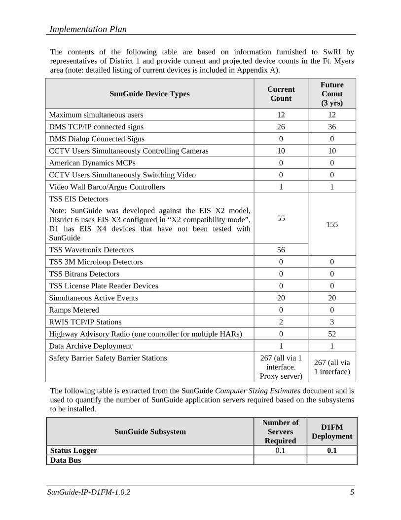
The contents of the following table are based on information furnished to SwRI by representatives of District 1 and provide current and projected device counts in the Ft. Myers area (note: detailed listing of current devices is included in Appendix A).
SunGuide Device Types Current Count
Future Count (3 yrs)
Maximum simultaneous users 12 12 DMS TCP/IP connected signs 26 36 DMS Dialup Connected Signs 0 0 CCTV Users Simultaneously Controlling Cameras 10 10 American Dynamics MCPs 0 0 CCTV Users Simultaneously Switching Video 0 0 Video Wall Barco/Argus Controllers 1 1 TSS EIS Detectors Note: SunGuide was developed against the EIS X2 model, District 6 uses EIS X3 configured in “X2 compatibility mode”, D1 has EIS X4 devices that have not been tested with SunGuide
55 155
TSS Wavetronix Detectors 56 TSS 3M Microloop Detectors 0 0 TSS Bitrans Detectors 0 0 TSS License Plate Reader Devices 0 0 Simultaneous Active Events 20 20 Ramps Metered 0 0 RWIS TCP/IP Stations 2 3 Highway Advisory Radio (one controller for multiple HARs) 0 52 Data Archive Deployment 1 1 Safety Barrier Safety Barrier Stations 267 (all via 1
interface. Proxy server)
267 (all via 1 interface)
The following table is extracted from the SunGuide Computer Sizing Estimates document and is used to quantify the number of SunGuide application servers required based on the subsystems to be installed.
SunGuide Subsystem Number of
Servers Required
D1FM Deployment
Status Logger 0.1 0.1 Data Bus

Implementation Plan
SunGuide-IP-D1FM-1.0.2 6
SunGuide Subsystem Number of
Servers Required
D1FM Deployment
Base system up to 500 ITS devices 0.5 0.5 Over 500 devices 0.5 0
User Interface For every 10 users simultaneously logged in (note that for sever estimation this was left at 0.5 even though 12 users were specified)
0.5 0.5
DMS (includes MAS) Base subsystem 0.5 1 For every 100 TCP/IP connected signs 0.5 0.5 For every 50 dialup signs (assumes 5 modems) 0.5 0
CCTV Control (includes Manual Control Panel [MCP]) Base subsystem 0.25 0.25 For every 10 users simultaneously controlling cameras 0.25 0.25
Video Switching Base subsystem 0.5 0 For every 10 users simultaneously switching video 0.1 0
Video Wall Base subsystem 0.25 0.25 For each Barco/Argus Controller 0.1 0.1
TSS Base subsystem 0.25 0.25 For every 300 detectors 0.5 0.5
Event Management Base subsystem for up to 20 concurrent events 0.25 0.25 For each 20 concurrent events over the base amount 0.25 0
Ramp Metering Base subsystem 0.5 0 For every 20 ramps 0.25 0
Roadway Weather Information System (RWIS) Base subsystem 0.25 0.25 For every 50 TCP/IP connected sensors 0.25 0.25
Highway Advisory Radio (HAR) Base subsystem 0.25 0 For every 50 HARs 0.1 0
Archive Base subsystem 0.5 0.5
Safety Barrier Base Subsystem 0.1 0.1 For every 50 Barriers 0.1 0.1
Travel Time (TvT)

Implementation Plan
SunGuide-IP-D1FM-1.0.2 7
SunGuide Subsystem Number of
Servers Required
D1FM Deployment
Base Subsystem 0.5 0.5 Web Servers (should be protected with a firewall)
General Web server 1 0 Center-to-Center interface server 0.5 0 Emergency Evacuation 0.5 0 Maintenance Management Systems 0.5 0
Total SunGuide Application Servers Needed 6.15
The above analysis suggests that 6.15 servers would be needed to support the SunGuide installation as has been discussed with FDOT. The sizing estimates in the Computer Sizing Estimates were based on best engineering judgment. After several installations it is clear that the estimates were conservative; Southwest Research Institute® (SwRI®) believes that given the number of devices and based on the number of subsystems being initially deployed in District 1 that four servers be dedicated to running SunGuide software with one being dedicated to the database is more than sufficient.
The following software needs to be installed on the servers before the software installation team arrives on-site:
• Microsoft Standard Server 2003 with all current updates from Microsoft
The software installation team assumes that FDOT will have licenses and installation media available for the following products:
• Microsoft Standard Server 2003 • Oracle 10g, version 10.1.0.2.0
The SunGuide software will be installed and configured on the following machines (the recommendations are based on the current number of devices and the number of devices expected in the future):
• Database Servers: o Oracle
• Application Server #1 (this will be the server Operators access in order to log into SunGuide):
o Executive Handler o Status Logger o Admin Editor o Notify Manager o User Interface (Internet Information Server [IIS] Web Server) o Data Bus o Video Wall o Center-to-Center plug-ins (this will need access to the FL-ATIS network once it is
deployed) • Application Server #2:
o Executive Handler

Implementation Plan
SunGuide-IP-D1FM-1.0.2 8
o MAS o DMS (and drivers) o Travel Time o CCTV (and drivers) o RWIS (and drivers)
• Application Server #3: o Executive Handler o TSS (and drivers) o IDS o Safety Barrier
• Application Server #4: o Executive Handler o Event Management o Reporting Subsystem o Response Plan Generator o Data Archive
During the installation activities, a VPN (Virtual Private Network) connection should be configured that will allow SwRI staff to access the D1 Ft., Myers computers from remote locations. This will facilitate any troubleshooting (the VPN can only be provided with District 1 approval).
2.2.2 Workstations
The following software must be installed on each workstation that will access the SunGuide software:
• Microsoft Windows XP, Service Pack 3 • Microsoft Internet Explorer 7.0 • Adobe SVG Viewer 3.03 (can be downloaded at no charge from the Adobe website)
2.2.3 Device Protocol Compliance For the devices being deployed, District 1 needs to verify that the protocol used by the devices to be controlled by the SunGuide software is compliant to the following protocols:
Subsystem Protocol Reference CCTV Control NTCIP 1205 v01.08 Amendment 1 v01.08 (August 2004) DMS NTCIP 1203, FDOT MIB (Sep 2001) RWIS NTCIP 1204 v02.18 (April 2004) Safety Barrier SunGuide protocol Traffic Detection EIS RTMS, Issue 2 (April 2003) Traffic Detection Wavetronix RTMS: SS105 SmartSensor Data Protocol V2.02 Video Wall Barco/Argus Apollo, version 1.8 of the API

Implementation Plan
SunGuide-IP-D1FM-1.0.2 9
In addition to verifying the protocols are compliant, the District 1 staff needs to verify the TCP/IP connectivity to the field devices prior to the on-site installation activities being performed. This can most simply be accomplished by using “ping” to verify that the device is accessible from the server room using the network that the SunGuide servers will be utilizing.
Past history from previous new SunGuide installations indicates that approximately 80% of deployment efforts are spent on device connectivity (future upgrades do not take this level of effort). In new deployments wiring issues, device configuration issues and network issues have been shown to take a lot of time to resolve. Any effort prior to the deployment using “test software” (often provided by the vendors) to communicate to the devices from computers in the control center can reduce the installation efforts.
2.2.4 Network Infrastructure The following sections described the network infrastructure that must be in place prior to installation of the SunGuide software.
2.2.4.1 Hardware Due to the client/server nature of the SunGuide software, TCP/IP is used to exchange data between application servers. Due to the web based implementation of the SunGuide user interface, each SunGuide workstation requires TCP/IP access to the SunGuide application servers. District 1 needs to verify that TCP/IP connectivity exists between all SunGuide application servers and SunGuide workstations.
Early in the development of requirements for SunGuide, FDOT made the decision that the devices should be connected via TCP/IP to the SunGuide application servers. There are a number of techniques to connect traditional serial ITS devices so that they can be accessed via TCP/IP, these techniques include the use of a terminal server (a box that has a TCP/IP connection and has multiple serial ports) or a port server (a box that has a TCP/IP connection and a single serial port). The only exception to the use of TCP/IP access is that DMS devices can be accessed via a modem or directly through a serial port if the connection is made through a Windows “COM” port on the SunGuide application server running the DMS device driver.

Implementation Plan
SunGuide-IP-D1FM-1.0.2 10
It is District 1’s responsibility to provide all necessary network hardware and cables to provide the required connectivity. The following high level network diagram depicts District 1’s network layout:
2.2.4.2 Software As the SunGuide software is configured, it will need access to various “standard” servers (e.g. a time server) that may be installed as part of the SunGuide installation or may be available as part of the greater FDOT network. The following network services need to be available and the details (e.g., host names, addresses) need to be available during the SunGuide software configuration:
• SMTP Mail Server (optional): The SunGuide notify manager needs to be able to send emails on major system events so SMTP mail server access is required.
• DNS Server (optional): The SunGuide applications utilize TCP/IP to exchange data and the applications can use either IP addresses or host names in their configuration files. Note that the use of DNS is preferred because using explicit IP addresses is less flexible than using hostnames.
Implementation Plan
SunGuide-IP-D1FM-1.0.2 11
• Time Server (optional): It is recommended that all SunGuide computers (workstations and servers) be synchronized to a common time source as it is desirable during diagnostics to have the same time on all SunGuide systems.
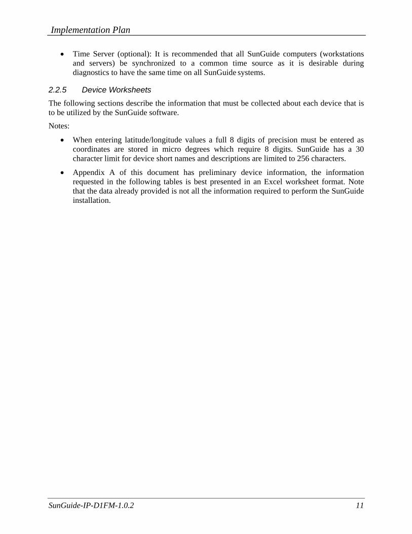
2.2.5 Device Worksheets The following sections describe the information that must be collected about each device that is to be utilized by the SunGuide software.
Notes:
• When entering latitude/longitude values a full 8 digits of precision must be entered as coordinates are stored in micro degrees which require 8 digits. SunGuide has a 30 character limit for device short names and descriptions are limited to 256 characters.
• Appendix A of this document has preliminary device information, the information requested in the following tables is best presented in an Excel worksheet format. Note that the data already provided is not all the information required to perform the SunGuide installation.

Implementation Plan
SunGuide-IP-D1FM-1.0.2 12
2.2.5.1 CCTV Worksheet The following data needs to be collected for each CCTV to be configured:
Camera Name Unique name of camera Center Id Unique name of center where camera resides
Protocol Specifies the protocol (values: SNMP, SNMP(PMPP)) for camera
Poll Process Name of driver for camera Manufacturer Manufacturer of camera Location Description Description of where camera resides Roadway Roadway of where camera resides Direction Direction of roadway where camera is installed Latitude Latitude of where camera resides Longitude Longitude of where camera resides
Op Status Operational status (values: Active, Error, Failed, OutOfService) of camera
Address Type1 Address type (values: pmppAddress, commAddress) for camera, if pmppAddress then camera uses SNMP (PMPP); if commAddress then camera uses SNMP
Address Type2 Specific address type (values: portServerAddress) of Address Type 1
Address Device address of camera Port Server IP IP address for the port server where camera resides Port Server Port Number Port number for the port server where camera resides Community Name Community name for camera (SNMP)
Attach to Video Device If selected, additional IP video parameters must be supplied.
The following data need to be provided for IP video:
Video Device IP Address IP address for encoder Blackout Determines if camera restricted Video Device Type Type (IP video device) of video device for encoder IP Streaming Driver ID Unique IP video switch driver name Card Number Card number for VBrick encoder
Manufacturer Manufacturer (values: Coretec, iMpath, Teleste, VBrick) of encoder
Model Model of encoder
Streaming Type Streaming type (values: elementary, transport, program) for encoder
Secondary Interface Secondary interface for VBrick encoder which enables users to maximize number of inputs for encoder
Snapshot Requested Determines if snapshots are generated for encoder
Implementation Plan
SunGuide-IP-D1FM-1.0.2 13
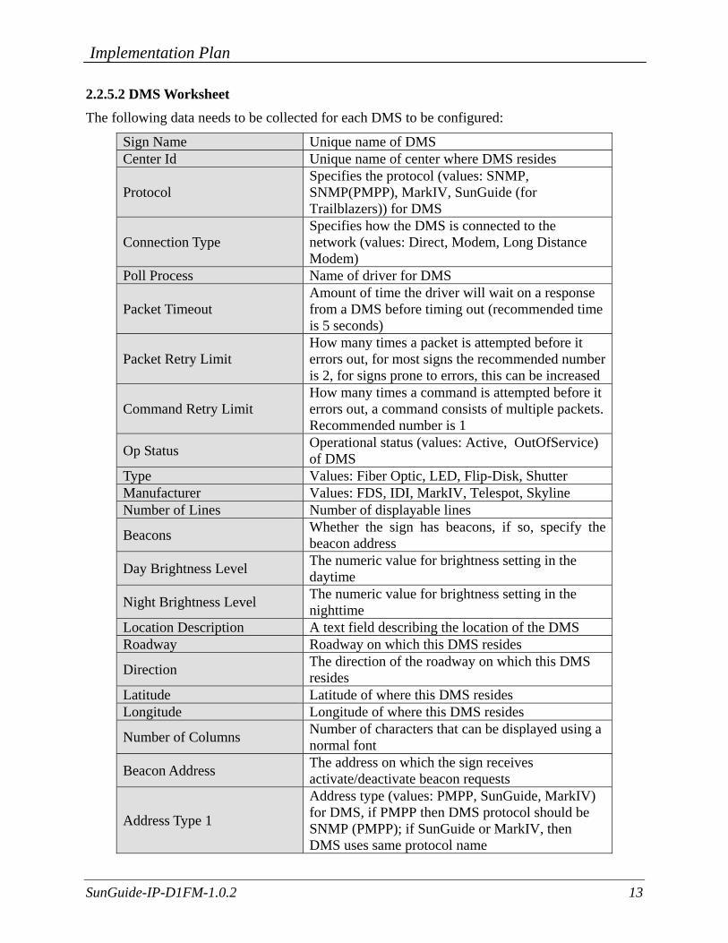
2.2.5.2 DMS Worksheet The following data needs to be collected for each DMS to be configured:
Sign Name Unique name of DMS Center Id Unique name of center where DMS resides
Protocol Specifies the protocol (values: SNMP, SNMP(PMPP), MarkIV, SunGuide (for Trailblazers)) for DMS
Connection Type Specifies how the DMS is connected to the network (values: Direct, Modem, Long Distance Modem)
Poll Process Name of driver for DMS
Packet Timeout Amount of time the driver will wait on a response from a DMS before timing out (recommended time is 5 seconds)
Packet Retry Limit How many times a packet is attempted before it errors out, for most signs the recommended number is 2, for signs prone to errors, this can be increased
Command Retry Limit How many times a command is attempted before it errors out, a command consists of multiple packets. Recommended number is 1
Op Status Operational status (values: Active, OutOfService) of DMS
Type Values: Fiber Optic, LED, Flip-Disk, Shutter Manufacturer Values: FDS, IDI, MarkIV, Telespot, Skyline Number of Lines Number of displayable lines
Beacons Whether the sign has beacons, if so, specify the beacon address
Day Brightness Level The numeric value for brightness setting in the daytime
Night Brightness Level The numeric value for brightness setting in the nighttime
Location Description A text field describing the location of the DMS Roadway Roadway on which this DMS resides
Direction The direction of the roadway on which this DMS resides
Latitude Latitude of where this DMS resides Longitude Longitude of where this DMS resides
Number of Columns Number of characters that can be displayed using a normal font
Beacon Address The address on which the sign receives activate/deactivate beacon requests
Address Type 1
Address type (values: PMPP, SunGuide, MarkIV) for DMS, if PMPP then DMS protocol should be SNMP (PMPP); if SunGuide or MarkIV, then DMS uses same protocol name

Implementation Plan
SunGuide-IP-D1FM-1.0.2 14
Address Type 2 Specific address type (values: Direct, PortServer, Dialup) of Address Type 1
Address Device address of DMS Community Name Community name for DMS (SNMP)
The following data need to be provided for DMSs connected via a TCP/IP connection:
IP Address IP address for the port server where DMS resides
Port Number Port number for the port server where DMS resides
The following data need to be provided for DMSs connected directly via a serial port:
Communications port Communications port to which the DMS is connected
Baud Rate This should match the baud rate of the DMS
Data Bits This should match the data bits the DMS is expecting
Stop Bits This should match the stop bits the DMS is expecting
Parity This should match the parity the DMS is expecting
The following data need to be provided for DMSs connected via a modem:
Phone Number Phone number for the DMS, should include any prefix needed for dialing
Baud Rate This should match the baud rate of the DMS

Implementation Plan
SunGuide-IP-D1FM-1.0.2 15
2.2.5.3 RWIS Worksheet The following data needs to be collected for each RIWS to be configured:
Sign Name Unique name of RWIS Protocol Should be NTCIP (only version supported)
Connection Type Specifies how the device is connected to the network (values: Direct, Modem, Long Distance Modem)
Op Status Operational status (values: Active, OutOfService) of device
Manufacturer Name of manufacturer Location Description A text field describing the location of the device Roadway Roadway on which this device resides
Direction The direction of the roadway on which this device resides
Latitude Latitude of where this device resides Longitude Longitude of where this DEVICE resides
Address Type 1 Address type (values: PMPP) for device, if PMPP then device protocol should be SNMP (PMPP)
Address Type 2 Specific address type (values: Direct, PortServer, Dialup) of Address Type 1
Address Device address of device Port Server IP IP address for the port server where device resides
Port Server Port Number Port number for the port server where device resides
Community Name Community name for device (SNMP)
2.2.5.4 Safety Barrier Worksheet The following data needs to be collected for each SB to be configured (note that in District 1 all communications will to a single IP address for all PLCs):
Station Name Unique name of device Roadway Roadway on which this device resides Location Description A text field describing the location of the device Latitude Latitude of where this device resides Longitude Longitude of where this device resides
Op Status Operational status (values: Active, OutOfService) of device
PLC ID The identifier of the PLC that is used to identify the device
Unit ID The unit identifier of the device within the PLC Address Device address of device IP Address IP address of the proxy server Port Number Port number
Implementation Plan
SunGuide-IP-D1FM-1.0.2 16
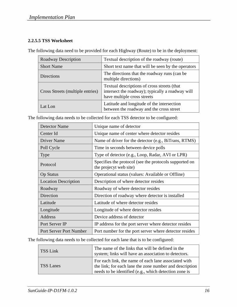
2.2.5.5 TSS Worksheet
The following data need to be provided for each Highway (Route) to be in the deployment:
Roadway Description Textual description of the roadway (route) Short Name Short text name that will be seen by the operators
Directions The directions that the roadway runs (can be multiple directions)
Cross Streets (multiple entries) Textual descriptions of cross streets (that intersect the roadway); typically a roadway will have multiple cross streets
Lat Lon Latitude and longitude of the intersection between the roadway and the cross street
The following data needs to be collected for each TSS detector to be configured:
Detector Name Unique name of detector Center Id Unique name of center where detector resides Driver Name Name of driver for the detector (e.g., BiTrans, RTMS) Poll Cycle Time in seconds between device polls Type Type of detector (e.g., Loop, Radar, AVI or LPR)
Protocol Specifies the protocol (see the protocols supported on the projecyt web site)
Op Status Operational status (values: Available or Offline) Location Description Description of where detector resides Roadway Roadway of where detector resides Direction Direction of roadway where detector is installed Latitude Latitude of where detector resides Longitude Longitude of where detector resides Address Device address of detector Port Server IP IP address for the port server where detector resides Port Server Port Number Port number for the port server where detector resides
The following data needs to be collected for each lane that is to be configured:
TSS Link The name of the links that will be defined in the system; links will have an association to detectors.
TSS Lanes For each link, the name of each lane associated with the link; for each lane the zone number and description needs to be identified (e.g., which detection zone is
Implementation Plan
SunGuide-IP-D1FM-1.0.2 17
associated with a lane).
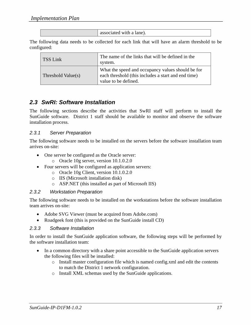
The following data needs to be collected for each link that will have an alarm threshold to be configured:
TSS Link The name of the links that will be defined in the system.
Threshold Value(s) What the speed and occupancy values should be for each threshold (this includes a start and end time) value to be defined.
2.3 SwRI: Software Installation The following sections describe the activities that SwRI staff will perform to install the SunGuide software. District 1 staff should be available to monitor and observe the software installation process.
2.3.1 Server Preparation The following software needs to be installed on the servers before the software installation team arrives on-site:
• One server be configured as the Oracle server: o Oracle 10g server, version 10.1.0.2.0
• Four servers will be configured as application servers: o Oracle 10g Client, version 10.1.0.2.0 o IIS (Microsoft installation disk) o ASP.NET (this installed as part of Microsoft IIS)
2.3.2 Workstation Preparation The following software needs to be installed on the workstations before the software installation team arrives on-site:
• Adobe SVG Viewer (must be acquired from Adobe.com) • Roadgeek font (this is provided on the SunGuide install CD)
2.3.3 Software Installation In order to install the SunGuide application software, the following steps will be performed by the software installation team:
• In a common directory with a share point accessible to the SunGuide application servers the following files will be installed:
o Install master configuration file which is named config.xml and edit the contents to match the District 1 network configuration.
o Install XML schemas used by the SunGuide applications.

Implementation Plan
SunGuide-IP-D1FM-1.0.2 18
• Execute the database creation scripts to prepare the database for installation of the SunGuide applications.
• Using the installation instructions in the SunGuide Version Description Document (VDD) and installation notes install the SunGuide applications. Any patches released subsequent to the release of the full installation CD need to be installed (in order) after the installation CD is executed.
Two SunGuide system administration applications do not execute in a browser environment. These applications should be installed on workstations that may be used to diagnose the health and status of the system; details of the application are contained in the SUM. SwRI will install the following applications on the two end workstations on the right side of the control room when looking at the video wall (per District 1 direction):
• Executive Handler viewer: provides an overview of currently operating SunGuide applications.
• Status Logger viewer: provides the ability to review the SunGuide application log files.
2.3.4 Software Configuration After the SunGuide software is installed, various configuration activities need to occur; the software installation team will perform the following configurations:
• Install and configure Status Logger on a single SunGuide application server (the SunGuide applications will log to this one instance of Status Logger).
• Install and configure Executive Handler server on all SunGuide application servers • Modify the IIS to restrict access to the SunGuide Admin utility to users specified by
District 1.
The SunGuide GUI is designed to load GUI components for the SunGuide applications. The loading (and overall performance) of the GUI can be improved if the GUI components associated with subsystems not installed is removed. The software installation team will remove the GUI components for the subsystems that were not installed; this is done because when the GUI is installed it includes the components for ALL SunGuide subsystems, this removal is done so that users do not see menu options for subsystems which are not installed and configured.
2.3.5 C2C Configuration During the SunGuide software configuration, the Center-to-Center (C2C) interfaces need to be configured so that the District 1 deployment can exchange information and command requests (assuming operators have the appropriate permissions) with other control centers and FL-ATIS. To achieve this exchange of data a TCP/IP path must be established between the cooperating centers, this requires agencies to make appropriate modifications to firewall and other network appliances that may restrict this type of data flow. The following SunGuide C2C components need to be installed on the District 1 servers:
• C2C Plug-in Publisher • C2C Plug-in Subscriber • C2C Extractor • C2C Provider • C2C Command Receiver

Implementation Plan
SunGuide-IP-D1FM-1.0.2 19
The C2C interface should then be tested to assure that the software is properly configured; this testing will be performed using the C2C Test Suite.
2.4 SwRI / D1FM: Post Software Installation (Configuration) The following sections describe the activities that the District 1 staff need to perform after the SunGuide software deployment. SwRI and PBS&J (ITS GC) staff will be available to assist and work with the District 1 staff to accomplish these activities. SwRI recommends that both the District 1 SunGuide administrator and at least one SunGuide operator be available during this process.
2.4.1 Populate Tables The following tables need to be populated using the SunGuide Administration tool:
• User Management: o Users o Groups o Workstations
• CCTV: o Device Tables
• DMS: o Device Tables o Approved Words
• RWIS: o Device Tables
• Safety Barrier: o Device Tables
• TSS: o Alarm Thresholds o Device Tables o Detector Maps o Poll Cycles
• Event Management: o Activity Types o Agencies o Agencies Contacts o Comment Types o Event Status Types o Event Types o Injury Types o Organizations o Location Configuration o Mailing Lists o Mailing Lists Contacts o Procedural Errors o Response Plans o Vehicle Tracking

Implementation Plan
SunGuide-IP-D1FM-1.0.2 20
o Weather Conditions • Reporting Subsystem:
o Reports o Reporting Groups
• Data Archive: Properties • Miscellaneous: Centers
The SunGuide Software User’s Manual (SUM) and Administrator Training slides should be consulted on use of these editors. To aid in future configuration, for any device that does not have an entry at least one entry for every possible device will be added; this will help illustrate how future entries should be structured (naming, option selection, etc.) and also verify that the Admin editor can read and write information to the appropriate tables.
2.4.2 Create Map Links Each implementation of SunGuide must have a Map Link layer created; this layer is used by the operator map to display instrumented sections of roadway as well as highway shields. This layer is displayed in conjunction with the DynaMap shape file data to provide a complete looking map on the operator workstation. The SUM has a section titled “Map Administration with Link Editor” that explains the use of this software. Additionally, the Map Link Editor should be used to create the shields that should be displayed.
2.4.3 DMS Linking File A device linking file needs to be created so that DMS devices can be selected for recommended Event response plans. The Software User’s Manual describes how to create this file.
2.5 SwRI / D1FM: Testing Once the configuration is complete and equipment is made available, a series of ad hoc tests will be performed to verify software operation. If District 1 wishes, the formal test cases from the SunGuide Software Integration Case Procedures (SICP) can be executed but this activity has not been performed in recent SunGuide deployments. Areas that will be tested / exercised include:
• CCTV: o Control of CCTV devices
• DMS: o Devices being polled o Control of DMS devices o DMS devices showing on map with status information
• RWIS Devices: o Devices being polled o RIWS data showing up on map
• Safety Barrier Devices: o Devices being polled o SB data showing up on map

Implementation Plan
SunGuide-IP-D1FM-1.0.2 21
• TSS Devices: o Devices being polled o TSS data showing up on map
• Video Wall Devices: o Switching videos to different viewers on the wal o Creating and changing video wall layouts
• Event Management: o Event Creation o Event Management o Response Plan Generation
• Reporting Subsystem: o Generate reports
• Various: o Test C2C plugin using XML tester to receive data o Verify Data Archive is configured to store TSS data (note that this subsystem will
not be used in the short term but will be configured for future use)
2.6 Training Training will be conducted in the District 1 control center as the installation is performed; the training will be both a hands-on that occurs during the installation and configuration activities as well as formal class. The following training will be provided to the District 1 personnel during the installation and configuration:
• Administrator Training - the intent of the System Administration/Deployment training is to prepare personnel to install/configure the SunGuide software and administer the SunGuide system on a daily basis. The following topics will be addressed during the hands-on training:
o Installation procedures o Backup procedures o Recovery procedures o Modifying hardware configurations o Tailoring of the system environment o Starting/stopping/restarting the system o Troubleshooting:
Executive Handler Status Logger
o Workstation installation

Implementation Plan
SunGuide-IP-D1FM-1.0.2 22
<<< Note that the Operator training will be provided by >>> <<< PBS&J – the scope of the class is their responsibility >>>
• Operator Training - the intent of the Operator/User Interface course is to prepare
personnel to use the SunGuideTM system on a daily basis in a typical operational mode. The course will include the following topics:
o SunGuide System Administration fundamentals o Executive Handler fundamentals o Status Logger fundamentals o Graphical User Interface (GUI)/Map fundamentals o Closed Circuit Television (CCTV) operations o Dynamic Message Sign (DMS) operations o Traffic Sensor Subsystem (TSS) fundamentals; including License Plate
Reader fundamentals o Video Switching fundamentals; o Travel Time fundamentals; including the enhanced Travel Time functionality
using LPR and AVI. o Center-to-Center (C2C) fundamentals
The training format consists of:
o Classroom instruction using PowerPoint presentation (8 hours) o Hands-on instruction using City’s SunGuide System (4 hours)
The operator training will be conducted at the District 1 Ft. Myers TMC during non-operational hours.

Implementation Plan
SunGuide-IP-D1FM-1.0.2 23
2.7 Deployment Schedule The following schedule is proposed for the deployment. The SunGuide installation is scheduled to occur the week of November 17, 2008. The installation team will need access to hardware devices throughout the implementation process. Note that if activities complete early then if District 1 and SwRI agree the timing for the following events may be modified to shorten the overall deployment schedule.
ID Task Name Duration
1 Preinstallation Activities (City of TLH Activities) 5 days2 Install Operating Systems 5 days3 Install / Configure Orac le 5 days4 Install / Configure Workstations 5 days5 Server Conf iguration / Verification 1 day6 Verif y server softw are 1 day7 Verif y configuration 1 day8 Verif y w orks tations 1 day9 Site Installation and Checkout 5 days?10 Insall SunGuide softw are 1 day?11 Conf igure SunGuide 1 day?12 Conf igure Devices 2 days13 Test Field Connectivity 3 days14 Softw are Tes ting 4 days15 Training 0.5 days16 Administrator Class (TBD - likely OJT) 3 hrs17 Operator Training (PBS&J) 4 hrs
12 12 12 12 12 12 12 12 12 12 12 12 12y -2 Day 1 Day 3 Day 5 Day 7 Day 9 Day 11
Implementation Plan
SunGuide-IP-D1FM-1.0.2 24
3. Notes None.

Implementation Plan
SunGuide-IP-D1FM-1.0.2
Appendix A
Current Device Listings
Implementation Plan
SunGuide-IP-D1FM-1.0.2 A-1
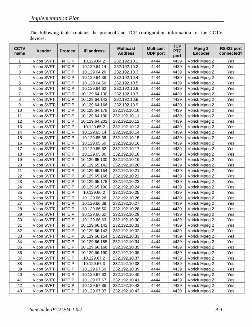
The following table contains the protocol and TCP configuration information for the CCTV devices:
CCTV name Vendor Protocol IP address Multicast
Address Multicast UDP port
TCP PTZ port
Mpeg 2 Encoder
RS422 port connected?
1 Vicon SVFT NTCIP 10.129.64.2 232.192.10.1 4444 4439 Vbrick Mpeg 2 Yes 2 Vicon SVFT NTCIP 10.129.64.14 232.192.10.2 4444 4439 Vbrick Mpeg 2 Yes 3 Vicon SVFT NTCIP 10.129.64.26 232.192.10.3 4444 4439 Vbrick Mpeg 2 Yes 4 Vicon SVFT NTCIP 10.129.64.38 232.192.10.4 4444 4439 Vbrick Mpeg 2 Yes 5 Vicon SVFT NTCIP 10.129.64.50 232.192.10.5 4444 4439 Vbrick Mpeg 2 Yes 6 Vicon SVFT NTCIP 10.129.64.62 232.192.10.6 4444 4439 Vbrick Mpeg 2 Yes 7 Vicon SVFT NTCIP 10.129.64.130 232.192.10.7 4444 4439 Vbrick Mpeg 2 Yes 8 Vicon SVFT NTCIP 10.129.64.142 232.192.10.8 4444 4439 Vbrick Mpeg 2 Yes 9 Vicon SVFT NTCIP 10.129.64.166 232.192.10.9 4444 4439 Vbrick Mpeg 2 Yes 10 Vicon SVFT NTCIP 10.129.64.178 232.192.10.10 4444 4439 Vbrick Mpeg 2 Yes 11 Vicon SVFT NTCIP 10.129.64.190 232.192.10.11 4444 4439 Vbrick Mpeg 2 Yes 12 Vicon SVFT NTCIP 10.129.64.202 232.192.10.12 4444 4439 Vbrick Mpeg 2 Yes 13 Vicon SVFT NTCIP 10.129.65.2 232.192.10.13 4444 4439 Vbrick Mpeg 2 Yes 14 Vicon SVFT NTCIP 10.129.65.14 232.192.10.14 4444 4439 Vbrick Mpeg 2 Yes 15 Vicon SVFT NTCIP 10.129.65.38 232.192.10.15 4444 4439 Vbrick Mpeg 2 Yes 16 Vicon SVFT NTCIP 10.129.65.50 232.192.10.16 4444 4439 Vbrick Mpeg 2 Yes 17 Vicon SVFT NTCIP 10.129.65.62 232.192.10.17 4444 4439 Vbrick Mpeg 2 Yes 18 Vicon SVFT NTCIP 10.129.65.86 232.192.10.18 4444 4439 Vbrick Mpeg 2 Yes 19 Vicon SVFT NTCIP 10.129.65.130 232.192.10.19 4444 4439 Vbrick Mpeg 2 Yes 20 Vicon SVFT NTCIP 10.129.65.142 232.192.10.20 4444 4439 Vbrick Mpeg 2 Yes 21 Vicon SVFT NTCIP 10.129.65.154 232.192.10.21 4444 4439 Vbrick Mpeg 2 Yes 22 Vicon SVFT NTCIP 10.129.65.166 232.192.10.22 4444 4439 Vbrick Mpeg 2 Yes 23 Vicon SVFT NTCIP 10.129.65.178 232.192.10.23 4444 4439 Vbrick Mpeg 2 Yes 24 Vicon SVFT NTCIP 10.129.65.190 232.192.10.24 4444 4439 Vbrick Mpeg 2 Yes 25 Vicon SVFT NTCIP 10.129.66.2 232.192.10.25 4444 4439 Vbrick Mpeg 2 Yes 26 Vicon SVFT NTCIP 10.129.66.26 232.192.10.26 4444 4439 Vbrick Mpeg 2 Yes 27 Vicon SVFT NTCIP 10.129.66.38 232.192.10.27 4444 4439 Vbrick Mpeg 2 Yes 28 Vicon SVFT NTCIP 10.129.66.50 232.192.10.28 4444 4439 Vbrick Mpeg 2 Yes 29 Vicon SVFT NTCIP 10.129.66.62 232.192.10.29 4444 4439 Vbrick Mpeg 2 Yes 30 Vicon SVFT NTCIP 10.129.66.63 232.192.10.30 4444 4439 Vbrick Mpeg 2 Yes 31 Vicon SVFT NTCIP 10.129.66.142 232.192.10.31 4444 4439 Vbrick Mpeg 2 Yes 32 Vicon SVFT NTCIP 10.129.66.143 232.192.10.32 4444 4439 Vbrick Mpeg 2 Yes 33 Vicon SVFT NTCIP 10.129.66.154 232.192.10.33 4444 4439 Vbrick Mpeg 2 Yes 34 Vicon SVFT NTCIP 10.129.66.155 232.192.10.34 4444 4439 Vbrick Mpeg 2 Yes 35 Vicon SVFT NTCIP 10.129.66.166 232.192.10.35 4444 4439 Vbrick Mpeg 2 Yes 36 Vicon SVFT NTCIP 10.129.66.190 232.192.10.36 4444 4439 Vbrick Mpeg 2 Yes 37 Vicon SVFT NTCIP 10.129.67.2 232.192.10.37 4444 4439 Vbrick Mpeg 2 Yes 38 Vicon SVFT NTCIP 10.129.67.3 232.192.10.38 4444 4439 Vbrick Mpeg 2 Yes 39 Vicon SVFT NTCIP 10.129.67.50 232.192.10.39 4444 4439 Vbrick Mpeg 2 Yes 40 Vicon SVFT NTCIP 10.129.67.62 232.192.10.40 4444 4439 Vbrick Mpeg 2 Yes 41 Vicon SVFT NTCIP 10.129.67.67 232.192.10.41 4444 4439 Vbrick Mpeg 2 Yes 42 Vicon SVFT NTCIP 10.129.67.86 232.192.10.42 4444 4439 Vbrick Mpeg 2 Yes 43 Vicon SVFT NTCIP 10.129.67.87 232.192.10.43 4444 4439 Vbrick Mpeg 2 Yes

Implementation Plan
SunGuide-IP-D1FM-1.0.2 A-2
CCTV name Vendor Protocol IP address Multicast
Address Multicast UDP port
TCP PTZ port
Mpeg 2 Encoder
RS422 port connected?
44 Vicon SVFT NTCIP 10.129.67.154 232.192.10.44 4444 4439 Vbrick Mpeg 2 Yes 45 Vicon SVFT NTCIP 10.129.67.178 232.192.10.45 4444 4439 Vbrick Mpeg 2 Yes 46 Vicon SVFT NTCIP 10.129.67.190 232.192.10.46 4444 4439 Vbrick Mpeg 2 Yes 47 Vicon SVFT NTCIP 10.129.67.191 232.192.10.47 4444 4439 Vbrick Mpeg 2 Yes 48 Vicon SVFT NTCIP 10.129.67.202 232.192.10.48 4444 4439 Vbrick Mpeg 2 Yes 49 Vicon SVFT NTCIP 10.129.67.238 232.192.10.49 4444 4439 Vbrick Mpeg 2 Yes 50 Vicon SVFT NTCIP 10.129.68.2 232.192.10.50 4444 4439 Vbrick Mpeg 2 Yes 51 Vicon SVFT NTCIP 10.129.68.38 232.192.10.51 4444 4439 Vbrick Mpeg 2 Yes 52 Vicon SVFT NTCIP 10.129.68.50 232.192.10.52 4444 4439 Vbrick Mpeg 2 Yes 53 Vicon SVFT NTCIP 10.129.68.51 232.192.10.53 4444 4439 Vbrick Mpeg 2 Yes 54 Vicon SVFT NTCIP 10.129.68.62 232.192.10.54 4444 4439 Vbrick Mpeg 2 Yes 55 Vicon SVFT NTCIP 10.129.68.98 232.192.10.55 4444 4439 Vbrick Mpeg 2 Yes 56 Vicon SVFT NTCIP 10.129.68.130 232.192.10.56 4444 4439 Vbrick Mpeg 2 Yes 57 Vicon SVFT NTCIP 10.129.68.142 232.192.10.57 4444 4439 Vbrick Mpeg 2 Yes 58 Vicon SVFT NTCIP 10.129.68.178 232.192.10.58 4444 4439 Vbrick Mpeg 2 Yes 59 Vicon SVFT NTCIP 10.129.68.190 232.192.10.59 4444 4439 Vbrick Mpeg 2 Yes 60 Vicon SVFT NTCIP 10.129.68.191 232.192.10.60 4444 4439 Vbrick Mpeg 2 Yes 61 Vicon SVFT NTCIP 10.129.68.202 232.192.10.61 4444 4439 Vbrick Mpeg 2 Yes 62 Vicon SVFT NTCIP 10.129.68.203 232.192.10.62 4444 4439 Vbrick Mpeg 2 Yes 63 Vicon SVFT NTCIP 10.129.69.2 232.192.10.63 4444 4439 Vbrick Mpeg 2 Yes 64 Vicon SVFT NTCIP 10.129.69.38 232.192.10.64 4444 4439 Vbrick Mpeg 2 Yes 65 Vicon SVFT NTCIP 10.129.69.50 232.192.10.65 4444 4439 Vbrick Mpeg 2 Yes 66 Vicon SVFT NTCIP 10.129.59.51 232.192.10.66 4444 4439 Vbrick Mpeg 2 Yes 67 Vicon SVFT NTCIP 10.129.69.74 232.192.10.67 4444 4439 Vbrick Mpeg 2 Yes 68 Vicon SVFT NTCIP 10.129.69.98 232.192.10.68 4444 4439 Vbrick Mpeg 2 Yes 69 Vicon SVFT NTCIP 10.129.69.130 232.192.10.69 4444 4439 Vbrick Mpeg 2 Yes 70 Vicon SVFT NTCIP 10.129.69.154 232.192.10.70 4444 4439 Vbrick Mpeg 2 Yes 71 Vicon SVFT NTCIP 10.129.69.155 232.192.10.71 4444 4439 Vbrick Mpeg 2 Yes 72 Vicon SVFT NTCIP 10.129.69.178 232.192.10.72 4444 4439 Vbrick Mpeg 2 Yes 73 Vicon SVFT NTCIP 10.129.69.190 232.192.10.73 4444 4439 Vbrick Mpeg 2 Yes 74 Vicon SVFT NTCIP 10.129.69.202 232.192.10.74 4444 4439 Vbrick Mpeg 2 Yes 75 Vicon SVFT NTCIP 10.129.70.26 232.192.10.75 4444 4439 Vbrick Mpeg 2 Yes 76 Vicon SVFT NTCIP 10.129.70.38 232.192.10.76 4444 4439 Vbrick Mpeg 2 Yes 77 Vicon SVFT NTCIP 10.129.70.62 232.192.10.77 4444 4439 Vbrick Mpeg 2 Yes 78 Vicon SVFT NTCIP 10.129.70.86 232.192.10.78 4444 4439 Vbrick Mpeg 2 Yes 79 Vicon SVFT NTCIP 10.129.70.98 232.192.10.79 4444 4439 Vbrick Mpeg 2 Yes
The following table contains the protocol and TCP configuration information for the DMS devices:
DMS name Vendor Protocol IP address
UDP Control
port
Read/Write Community
name Lines by Columns
Sign Type
1 Adaptive Micro Displays NTCIP(SNMP) 10.129.64.64 300 public 3 by18 Char 2 Adaptive Micro Displays NTCIP(SNMP) 10.129.64.154 300 public 4 by18 Char

Implementation Plan
SunGuide-IP-D1FM-1.0.2 A-3
DMS name Vendor Protocol IP address
UDP Control
port
Read/Write Community
name Lines by Columns
Sign Type
3 Adaptive Micro Displays NTCIP(SNMP) 10.129.65.26 300 public 5 by18 Char 4 Adaptive Micro Displays NTCIP(SNMP) 10.129.65.74 300 public 6 by18 Char 5 Adaptive Micro Displays NTCIP(SNMP) 10.129.66.14 300 public 7 by18 Char 6 Adaptive Micro Displays NTCIP(SNMP) 10.129.66.130 300 public 8 by18 Char 7 Adaptive Micro Displays NTCIP(SNMP) 10.129.66.178 300 public 9 by18 Char 8 Adaptive Micro Displays NTCIP(SNMP) 10.129.67.26 300 public 10 by18 Char 9 Adaptive Micro Displays NTCIP(SNMP) 10.129.67.38 300 public 11 by18 Char 10 Adaptive Micro Displays NTCIP(SNMP) 10.129.67.142 300 public 12 by18 Char 11 Adaptive Micro Displays NTCIP(SNMP) 10.129.67.166 300 public 13 by18 Char 12 Adaptive Micro Displays NTCIP(SNMP) 10.129.67.214 300 public 14 by18 Char 13 Adaptive Micro Displays NTCIP(SNMP) 10.129.68.26 300 public 15 by18 Char 14 Adaptive Micro Displays NTCIP(SNMP) 10.129.68.74 300 public 16 by18 Char 15 Adaptive Micro Displays NTCIP(SNMP) 10.129.68.86 300 public 17 by18 Char 16 Adaptive Micro Displays NTCIP(SNMP) 10.129.68.154 300 public 18 by18 Char 17 Adaptive Micro Displays NTCIP(SNMP) 10.129.68.166 300 public 19 by18 Char 18 Adaptive Micro Displays NTCIP(SNMP) 10.129.69.14 300 public 20 by18 Char 19 Adaptive Micro Displays NTCIP(SNMP) 10.129.69.26 300 public 21 by18 Char 20 Adaptive Micro Displays NTCIP(SNMP) 10.129.69.62 300 public 22 by18 Char 21 Adaptive Micro Displays NTCIP(SNMP) 10.129.69.86 300 public 23 by18 Char 22 Adaptive Micro Displays NTCIP(SNMP) 10.129.69.142 300 public 24 by18 Char 23 Adaptive Micro Displays NTCIP(SNMP) 10.129.69.166 300 public 25 by18 Char 24 Adaptive Micro Displays NTCIP(SNMP) 10.129.70.2 300 public 26 by18 Char 25 Adaptive Micro Displays NTCIP(SNMP) 10.129.70.14 300 public 27 by18 Char 26 Adaptive Micro Displays NTCIP(SNMP) 10.129.70.50 300 public 28 by18 Char
The following table contains the protocol and TCP configuration information for the RWIS devices:
RWIS name Vendor RPU Protocol IP address 1 Quixote SSI linux NTCIP 1204 v02.18 10.129.65.202 2 Quixote SSI linux NTCIP 1204 v02.18 10.129.69.203
The following table contains the protocol and TCP configuration information for the Safety Barrier devices (note: SunGuide will talk to a Proxy Server that is at IP 10.128.0.8, this IP corresponds to a Windows XP64 server that will be hosting SIMREX's Proxy server):
Master radio name Vendor Protocol IP address 1 Simrex Sunguide 10.129.64.3 2 Simrex Sunguide 10.129.64.15 3 Simrex Sunguide 10.129.64.27 4 Simrex Sunguide 10.129.64.39 5 Simrex Sunguide 10.129.64.51 6 Simrex Sunguide 10.129.64.63 7 Simrex Sunguide 10.129.64.1318 Simrex Sunguide 10.129.64.143

Implementation Plan
SunGuide-IP-D1FM-1.0.2 A-4
Master radio name Vendor Protocol IP address 9 Simrex Sunguide 10.129.64.16710 Simrex Sunguide 10.129.64.17911 Simrex Sunguide 10.129.64.19112 Simrex Sunguide 10.129.64.20313 Simrex Sunguide 10.129.65.3 14 Simrex Sunguide 10.129.65.15 15 Simrex Sunguide 10.129.65.39 16 Simrex Sunguide 10.129.65.51 17 Simrex Sunguide 10.129.65.87 18 Simrex Sunguide 10.129.65.14319 Simrex Sunguide 10.129.65.15520 Simrex Sunguide 10.129.65.16721 Simrex Sunguide 10.129.65.17922 Simrex Sunguide 10.129.65.19123 Simrex Sunguide 10.129.66.3 24 Simrex Sunguide 10.129.66.27
The following table contains the protocol and TCP configuration information for the TSS devices (note that the SunGuide TSS driver does not support the some of the most recent RTMS protocols available, devices will need to be set in the proper configuration to utilize the older protocols until SunGuide is upgraded – see the protocol section of this document as to the versions supported):
MVDS Name Vendor/model Protocol IP address TCP port
number Comm via
TS? 1 RTMS X4 RTMS 10.129.64.4 2000 no 2 RTMS X4 RTMS 10.129.64.16 2000 no 3 RTMS X4 RTMS 10.129.64.28 2000 no 4 RTMS X4 RTMS 10.129.64.40 2000 no 5 RTMS X4 RTMS 10.129.64.52 2000 no 6 RTMS X4 RTMS 10.129.64.65 2000 no 7 RTMS X4 RTMS 10.129.64.132 2000 no 8 RTMS X4 RTMS 10.129.64.144 2000 no 9 RTMS X4 RTMS 10.129.64.168 2000 no 10 RTMS X4 RTMS 10.129.64.180 2000 no 11 RTMS X4 RTMS 10.129.64.192 2000 no 12 RTMS X4 RTMS 10.129.64.204 2000 no 13 RTMS X4 RTMS 10.129.65.4 2000 no 14 RTMS X4 RTMS 10.129.65.16 2000 no 15 RTMS X4 RTMS 10.129.65.40 2000 no 16 RTMS X4 RTMS 10.129.65.52 2000 no 17 RTMS X4 RTMS 10.129.65.53 2000 no 18 RTMS X4 RTMS 10.129.65.54 2000 no 19 RTMS X4 RTMS 10.129.65.55 2000 no 20 RTMS X4 RTMS 10.129.65.63 2000 no 21 RTMS X4 RTMS 10.129.65.88 2000 no 22 RTMS X4 RTMS 10.129.65.131 2000 no

Implementation Plan
SunGuide-IP-D1FM-1.0.2 A-5
MVDS Name Vendor/model Protocol IP address TCP port
number Comm via
TS? 23 RTMS X4 RTMS 10.129.65.144 2000 no 24 RTMS X4 RTMS 10.129.65.156 2000 no 25 RTMS X4 RTMS 10.129.65.168 2000 no 26 RTMS X4 RTMS 10.129.65.180 2000 no 27 RTMS X4 RTMS 10.129.65.192 2000 no 28 RTMS X4 RTMS 10.129.66.4 2000 no 29 RTMS X4 RTMS 10.129.66.28 2000 no 30 RTMS X4 RTMS 10.129.66.51 2000 no 31 Wavetronix SS105 Wavetronix 10.129.66.52 4001 yes 32 Wavetronix SS105 Wavetronix 10.129.66.53 4001 yes 33 RTMS X4 RTMS 10.129.66.54 2000 no 34 Wavetronix SS105 Wavetronix 10.129.66.64 4001 yes 35 Wavetronix SS105 Wavetronix 10.129.66.65 4001 yes 36 Wavetronix SS105 Wavetronix 10.129.66.143 4001 yes 37 Wavetronix SS105 Wavetronix 10.129.66.144 4001 yes 38 RTMS X4 RTMS 10.129.66.167 2000 no 39 Wavetronix SS105 Wavetronix 10.129.66.168 4001 yes 40 Wavetronix SS105 Wavetronix 10.129.66.169 4001 yes 41 RTMS X4 RTMS 10.129.66.170 no 42 Wavetronix SS105 Wavetronix 10.129.66.179 4001 yes 43 Wavetronix SS105 Wavetronix 10.129.66.191 4001 yes 44 RTMS X4 RTMS 10.129.67.4 2000 no 45 RTMS X4 RTMS 10.129.67.5 2000 no 46 Wavetronix SS105 Wavetronix 10.129.67.14 4001 yes 47 Wavetronix SS105 Wavetronix 10.129.67.51 4001 yes 48 Wavetronix SS105 Wavetronix 10.129.67.52 4001 yes 49 Wavetronix SS105 Wavetronix 10.129.67.63 4001 yes 50 RTMS X4 RTMS 10.129.67.68 2000 no 51 Wavetronix SS105 Wavetronix 10.129.67.88 4001 yes 52 Wavetronix SS105 Wavetronix 10.129.67.89 4001 yes 53 Wavetronix SS105 Wavetronix 10.129.67.90 4001 yes 54 RTMS X4 RTMS 10.129.67.91 2000 no 55 Wavetronix SS105 Wavetronix 10.129.67.130 4001 yes 56 Wavetronix SS105 Wavetronix 10.129.67.155 4001 yes 57 Wavetronix SS105 Wavetronix 10.129.67.179 4001 yes 58 RTMS X4 RTMS 10.129.67.192 2000 no 59 RTMS X4 RTMS 10.129.67.193 2000 no 60 Wavetronix SS105 Wavetronix 10.129.67.203 4001 yes 61 Wavetronix SS105 Wavetronix 10.129.67.226 4001 yes 62 Wavetronix SS105 Wavetronix 10.129.67.227 4001 yes 63 Wavetronix SS105 Wavetronix 10.129.67.239 4001 yes 64 Wavetronix SS105 Wavetronix 10.129.67.240 4001 yes 65 Wavetronix SS105 Wavetronix 10.129.68.3 4001 yes 66 Wavetronix SS105 Wavetronix 10.129.68.4 4001 yes 67 Wavetronix SS105 Wavetronix 10.129.68.14 4001 yes 68 Wavetronix SS105 Wavetronix 10.129.68.15 4001 yes 69 Wavetronix SS105 Wavetronix 10.129.68.39 4001 yes

Implementation Plan
SunGuide-IP-D1FM-1.0.2 A-6
MVDS Name Vendor/model Protocol IP address TCP port
number Comm via
TS? 70 Wavetronix SS105 Wavetronix 10.129.68.40 4001 yes 71 RTMS X4 RTMS 10.129.68.52 2000 no 72 RTMS X4 RTMS 10.129.68.53 2000 no 73 Wavetronix SS105 Wavetronix 10.129.68.63 4001 yes 74 Wavetronix SS105 Wavetronix 10.129.68.87 4001 yes 75 Wavetronix SS105 Wavetronix 10.129.68.99 4001 yes 76 RTMS X4 RTMS 10.129.68.131 2000 no 77 Wavetronix SS105 Wavetronix 10.129.68.132 4001 yes 78 RTMS X4 RTMS 10.129.68.133 2000 no 79 Wavetronix SS105 Wavetronix 10.129.68.143 4001 yes 80 Wavetronix SS105 Wavetronix 10.129.68.167 4001 yes 81 Wavetronix SS105 Wavetronix 10.129.68.179 4001 yes 82 RTMS X4 RTMS 10.129.68.192 2000 no 83 RTMS X4 RTMS 10.129.68.193 2000 no 84 Wavetronix SS105 Wavetronix 10.129.68.204 4001 yes 85 Wavetronix SS105 Wavetronix 10.129.68.205 4001 yes 86 Wavetronix SS105 Wavetronix 10.129.69.3 4001 yes 87 Wavetronix SS105 Wavetronix 10.129.69.4 4001 yes 88 Wavetronix SS105 Wavetronix 10.129.69.39 4001 yes 89 RTMS X4 RTMS 10.129.69.52 2000 no 90 RTMS X4 RTMS 10.129.69.53 2000 no 91 Wavetronix SS105 Wavetronix 10.129.69.75 4001 yes 92 RTMS X4 RTMS 10.129.69.99 2000 no 93 RTMS X4 RTMS 10.129.69.100 2000 no 94 Wavetronix SS105 Wavetronix 10.129.69.131 4001 yes 95 RTMS X4 RTMS 10.129.69.156 2000 no 96 RTMS X4 RTMS 10.129.69.157 2000 no 97 Wavetronix SS105 Wavetronix 10.129.69.179 4001 yes 98 RTMS X4 RTMS 10.129.69.191 2000 no 99 Wavetronix SS105 Wavetronix 10.129.69.192 4001 yes 100 Wavetronix SS105 Wavetronix 10.129..69.193 4001 yes 101 RTMS X4 RTMS 10.129.69.194 2000 no 102 Wavetronix SS105 Wavetronix 10.129.69.204 4001 yes 103 RTMS X4 RTMS 10.129.70.27 2000 no 104 RTMS X4 RTMS 10.129.70.28 2000 no 105 Wavetronix SS105 Wavetronix 10.129.70.39 4001 yes 106 Wavetronix SS105 Wavetronix 10.129.70.40 4001 yes 107 Wavetronix SS105 Wavetronix 10.129.70.63 4001 yes 108 Wavetronix SS105 Wavetronix 10.129.70.74 4001 yes 109 Wavetronix SS105 Wavetronix 10.129.70.87 4001 yes 110 Wavetronix SS105 Wavetronix 10.129.70.99 4001 yes 111 Wavetronix SS105 Wavetronix 10.129.70.100 4001 yes